US7256714B2 - Keyboard with reduced keying ambiguity - Google Patents
Keyboard with reduced keying ambiguityDownload PDFInfo
- Publication number
- US7256714B2 US7256714B2US11/160,885US16088505AUS7256714B2US 7256714 B2US7256714 B2US 7256714B2US 16088505 AUS16088505 AUS 16088505AUS 7256714 B2US7256714 B2US 7256714B2
- Authority
- US
- United States
- Prior art keywords
- key
- keys
- value
- controller
- signal
- Prior art date
- Legal status (The legal status is an assumption and is not a legal conclusion. Google has not performed a legal analysis and makes no representation as to the accuracy of the status listed.)
- Expired - Lifetime, expires
Links
Images


Classifications
- G—PHYSICS
- G10—MUSICAL INSTRUMENTS; ACOUSTICS
- G10H—ELECTROPHONIC MUSICAL INSTRUMENTS; INSTRUMENTS IN WHICH THE TONES ARE GENERATED BY ELECTROMECHANICAL MEANS OR ELECTRONIC GENERATORS, OR IN WHICH THE TONES ARE SYNTHESISED FROM A DATA STORE
- G10H1/00—Details of electrophonic musical instruments
- G10H1/32—Constructional details
- G10H1/34—Switch arrangements, e.g. keyboards or mechanical switches specially adapted for electrophonic musical instruments
- G—PHYSICS
- G06—COMPUTING OR CALCULATING; COUNTING
- G06F—ELECTRIC DIGITAL DATA PROCESSING
- G06F3/00—Input arrangements for transferring data to be processed into a form capable of being handled by the computer; Output arrangements for transferring data from processing unit to output unit, e.g. interface arrangements
- G06F3/01—Input arrangements or combined input and output arrangements for interaction between user and computer
- G06F3/02—Input arrangements using manually operated switches, e.g. using keyboards or dials
- G06F3/023—Arrangements for converting discrete items of information into a coded form, e.g. arrangements for interpreting keyboard generated codes as alphanumeric codes, operand codes or instruction codes
- H—ELECTRICITY
- H03—ELECTRONIC CIRCUITRY
- H03K—PULSE TECHNIQUE
- H03K17/00—Electronic switching or gating, i.e. not by contact-making and –breaking
- H03K17/94—Electronic switching or gating, i.e. not by contact-making and –breaking characterised by the way in which the control signals are generated
- H03K17/96—Touch switches
- H03K17/962—Capacitive touch switches
- H03K17/9622—Capacitive touch switches using a plurality of detectors, e.g. keyboard
- G—PHYSICS
- G10—MUSICAL INSTRUMENTS; ACOUSTICS
- G10H—ELECTROPHONIC MUSICAL INSTRUMENTS; INSTRUMENTS IN WHICH THE TONES ARE GENERATED BY ELECTROMECHANICAL MEANS OR ELECTRONIC GENERATORS, OR IN WHICH THE TONES ARE SYNTHESISED FROM A DATA STORE
- G10H2220/00—Input/output interfacing specifically adapted for electrophonic musical tools or instruments
- G10H2220/155—User input interfaces for electrophonic musical instruments
- G10H2220/265—Key design details; Special characteristics of individual keys of a keyboard; Key-like musical input devices, e.g. finger sensors, pedals, potentiometers, selectors
- H—ELECTRICITY
- H03—ELECTRONIC CIRCUITRY
- H03K—PULSE TECHNIQUE
- H03K2217/00—Indexing scheme related to electronic switching or gating, i.e. not by contact-making or -breaking covered by H03K17/00
- H03K2217/94—Indexing scheme related to electronic switching or gating, i.e. not by contact-making or -breaking covered by H03K17/00 characterised by the way in which the control signal is generated
- H03K2217/96—Touch switches
- H03K2217/9607—Capacitive touch switches
- H03K2217/960705—Safety of capacitive touch and proximity switches, e.g. increasing reliability, fail-safe
Definitions
- the inventionrelates to method and apparatus for controlling an array of touch or proximity sensors, and, more specifically for preventing accidental false inputs from keys adjacent to a selected key in a keyboard.
- Capacitive sensorscan be made in small sizes, which is desirable if a small, tightly packed keyboard is required; and 2) Capacitive sensors are particularly easy to environmentally seal, which is desirable if the keyboard is to be used in a wet environment or where there is a concern that contaminants may be spilled on the keyboard.
- One aspect of the teaching of that patentis the provision of apparatus for measuring a capacitance to ground of a plate, the apparatus comprising: a control means; a charging means connecting the plate to a voltage source supplying a first selected voltage; a discharging means responsive to a discharging output from the control means to connect the plate to a charge measurement capacitor that has a selected capacitance value and that has a first of its two terminals maintained at a second selected voltage, the second of the terminals supplying a voltage output representative of the capacitance to ground of the plate.
- 5,730,165teaches a method of operating a capacitive sensor for sensing the presence of an object proximate a sensing plate by measuring a change in a capacitance to an electrical ground.
- This methodcomprises the steps of: a) setting an output of a charge detector comprising filter means to a first selected voltage; b) charging the plate from a voltage source to a second selected voltage; c) discharging, for a selected discharging interval, the plate into the charge detector; d) repeating steps b) through c); and e) reading an output of the charge detector as a representation of the capacitance of the plate.
- 5,730,165is a method of operating a capacitive sensor electrically connected between an electrical ground and a sensing plate disposed adjacent an external surface of a first object (e.g., a keyboard), the sensor measuring a capacitive change responsive to a second object (e.g., a user's finger) adjacent the first object, where the two objects are separately electrically coupled to the ground, the method comprising the steps of: a) charging the plate from a voltage source; b) connecting, for a discharging interval having a selected discharging duration, the plate to a charge detector having an output representative of the change of the capacitance to ground of the plate; and c) reading the output of the charge detector.
- a first objecte.g., a keyboard
- a second objecte.g., a user's finger
- This apparatuscomprises at least three switching elements, each of the at least three switching elements having both a respective open state and a single respective closed state, each of the at least three switching elements electrically connected to one of two distinct reference voltages; a sample capacitor having a proximal one of its two terminals connected to the plate by means not comprising one of the switching elements; a voltage measurement circuit connected to one of the terminals of the sample capacitor by means not comprising one of the switching elements, the measurement circuit comprising one of a logic gate and a voltage comparator.
- a first of the at least three switching elementsconnects the distal terminal of the sample capacitor to the first reference voltage when in its closed state and disconnects the distal terminal from the first reference voltage when in its open state.
- a second of the at least three switching elementsconnects the proximal terminal of the sample capacitor to the second reference voltage when in its closed state and disconnects the proximal terminal from the second reference voltage when in its open state.
- the third of the at least three switching elementsconnects the distal terminal of the sample capacitor to the second reference voltage when in its closed state and disconnects the distal terminal from the second reference voltage when in its open state.
- the apparatusfurther comprises a controller for operating the at least three switching elements so that at any time at least one of the at least three switching elements is in its respective open state.
- each keycomprises a respective capacitive sensor for sensing the presence of an object proximate thereto and wherein each key is disposed adjacent a respective intersection of an input line and an output line.
- each of the keyscomprises a respective driven plate connected to one of the N input lines and a respective receiving plate connected to one of the M output lines; each of the input lines is electrically connected to a respective signal generator for supplying a respective periodic plurality of voltage cycles to each of the driven plates connected to it.
- controllerfor controlling each of a plurality of switching elements in an arrangement in which it controls a first selected number of the plurality of switching elements so as to connect each of the receiving plates to a reference potential when that receiving plate is not connected to one of the two terminals of a charge integrator that can be selectively connected to at least one of the receiving plates during a selected portion of the respective voltage cycle supplied to the driven plate associated with the at least one of the receiving plates, the charge integrator directly connected to at least a first of the plurality of switching elements.
- measurement circuitfor measuring a voltage on the charge integrator as an indication of the proximate presence of the object.
- One aspect of the inventionis that it provides an iterative method of removing keying ambiguity by repeatedly measuring a detected signal strength associated with each key in an array of keys having respective output signals responsive to a degree of coupling between the key and a user, comparing the measured signal strengths to find a maximum, determining that the key having the maximum signal strength is the unique user-selected key and suppressing or ignoring signals from all other keys as long as the signal from the selected key remains above some nominal threshold value.
- the array under considerationmay be a keyboard or any convenient subset thereof.
- Capacitive sensorsunlike bistable electromechanical switches which are either open or closed, provide a signal that varies with the degree of touch or extent or coupling between a user's finger and a sensing element of a keyboard.
- Other non-bistable touch sensorssuch as an array of piezoelectric sensors in which the output from a given sensor increases with increasing activation force, share many of the properties of capacitive keys.
- much of the subsequent disclosureshould be understood as being relevant to non-capacitive keys that also provide an output signal responsive to a degree of coupling between the key and a user's finger, stylus, or other actuation implement.
- a non-bistable keyboardsuch as a capacitive keyboard, in which each key has a respective detection integrator counter (DIC) associated with it.
- DICdetection integrator counter
- Each DICis a clocked counter that counts up by one incremental value on each clock cycle during which a signal strength from the associated key is above some nominal threshold value, and that counts down by one value if the signal strength is less than the nominal value.
- a controllerreceives a respective input from each DIC and determines that one of the keys is active, or selected, when the detection integration (DI) count associated with that key exceeds a selected terminal count value, TC.
- DIdetection integration
- the controllercontrols all of the detection integrators associated with keys in a selected neighborhood of the active key to stop counting until the count associated with the active key falls below the selected terminal count value—i.e., until the key that had been active becomes inactive.
- the signal from one key having a DI count close to TCis compared with the signals from other keys in a neighborhood, and if a signal from one of the other keys is greater than that from the one selected key during the time period before the one selected key is determined to be active, the selected key is cleared of its pending detection status, which may be done by clearing its DIC.
- the selected keyis declared to be active and the other keys are cleared of their pending active conditions, if any. This may be done by clearing their DIC's.
- an algorithm executed by a controlleris used to declare one of the two keys to be active and the other to be inactive. It will be recognized that a wide variety of algorithms are possible and include, but are not limited to, a random, or pseudo-random selection of the active key, or a declaration of activity based on which key was scanned first.
- the principlealso applies in the minimal case where the DIC's terminal count (TC) is chosen to be equal to one. This is functionally the same as though there were no DIC, but rather just a simple signal comparison function with an inhibiting logic gate following it.
- the inputs to the inhibiting gatealso includes the logical comparisons of the signal strengths among the keys in the neighborhood.
- a neighborhood of a given keymay consist of all the keys immediately adjacent the given key, or may comprise all the keys having no more than one key between them and the given key.
- the neighborhoodmay comprise all the keys in a matrix array—e.g., in a keyboard for use in a numerical data entry application in which only one key is to be active at a time so that the sequence of input digits is uniquely determined.
- the neighborhood of a keymay comprise all other keys in the keyboard except for special purpose keys, such as a capitalization shift key, a control key, and the like.
- some embodiments of the inventionprovide a keyboard that is configurable by a user who programs a controller to selectively consider or ignore various keys in an array.
- FIG. 1is a schematic block diagram of apparatus of the invention.
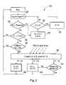
- FIG. 2is a flow chart showing logical operations carried out in a preferred method of the invention.
- FIG. 3is schematic circuit diagram of an apparatus of the invention using hardwired logic.
- FIG. 4is a schematic diagram of a logic block portion of the hardwired logic circuit of FIG. 3 .
- FIG. 1one finds a schematic representation of apparatus of the invention 10 , comprising an array of N sensors 12 , which are preferably capacitive proximity sensors, and which are labeled “Key 1”, . . . , “Key N”.
- Each of the sensors 12has respective outputs to both a respective counter 14 that supplies data to and is controlled by suitable control logic 16 and a respective output directly to the control logic.
- suitable control logic 16Those skilled in the electronic arts will appreciate that although the counters 14 and control logic 16 are depicted with discrete blocks in the schematic diagram, these features could be provided either by separate physical circuit elements, or could all be provided by a single microcontroller 18 , as depicted by the dashed phantom line in FIG. 1 .
- the control logicmay also contain other linear signal processing elements such as filters and/or nonlinear functions such as threshold comparisons.
- the array of keys 12is depicted as being a simple linear array, it will be appreciated by one who reads the complete disclosure contained herein that many other sorts of arrays can be used and will encompass, without being limited to, arrays used as computer keyboards, keypads of the sort commonly used in telephony and automated banking, cash register data input keyboards, etc.
- prior art capacitive keyboard arrayssense the proximate presence of a user's finger adjacent or abutting a single selected key.
- a problemarises, however, when the user touches more than one key, or when a conductive film bridges more than one key 12 so as to define an ambiguous touch area 20 as depicted by the single-dotted phantom curve in FIG. 1 .
- the addition of counters 14or of the logical functional equivalent thereof, when used in the accordance with the teachings of this disclosure, can remove or resolve such ambiguities by methods involving comparison of signal strengths from various keys 12 .
- FIG. 2one finds a flow chart of a preferred method 22 of the invention for operating apparatus 10 to suppress extraneous key signals or to otherwise resolve keying ambiguities.
- This method 22may be carried out by a microprocessor 18 operating under control of a program stored in a, preferably non-volatile, computer memory, or may be carried out by means of discrete circuit elements connected to provide hardwired logic.
- the chart of FIG. 2depicts operation in terms of a single sensor 12 , variously labeled “Key 1” or “K1”, it will be understood that this simplification is solely in the interest of clarity of presentation and that an algorithm controlling an actual keyboard could carry out substantially the depicted method for each of the N keys in a parallel fashion.
- the depicted methodrelies on iterated comparisons of sensor outputs, and selects a single sensor output based on that sensor both having an output in excess of a detection threshold for some selected number of counter cycles and thereafter having the highest output of all the sensors in the array that have also exceeded the detection threshold for the selected number of cycles of the counters. It will be recognized that one could choose to clock all the counters in parallel in order to achieve this, or that one could scan through the counters and operate them one at a time in rapid succession so as to provide the selected number of counter cycles for each sensor within a sufficiently short time period that a user could not perceive a delay in operation of the keyboard.
- a signal S 1 , acquired from sensor key K 1 (block 24 )is compared with a selected signal threshold value (block 26 ). If S 1 is less than the threshold value, the value, D 1 , in the DIC associated with K 1 is decremented (block 28 ) if that value is greater than zero. The new value of D 1 is then checked to see if it is zero (block 30 ), and, if so, K 1 is determined to be OFF (block 32 ). In keyboards comprising a large number of keys, only one of which should be active at a time, this OFF status will, of course, be the predominant result of an analysis of the output of any given key.
- the DIC value D 1is compared with a terminal count TC, as depicted in block 34 , where the expression TC ⁇ 1 is used to denote a count that is on the verge of triggering detection. If D 1 is below the TC, D 1 is incremented to a limit of TC and the acquisition 24 and signal threshold comparison 26 steps are repeated. If D 1 is at the critical value TC, the program then determines if another key has been selected as the touched key in a previous iteration, i.e., is already ON (block 36 ).
- the output from K 1is ignored and the process is iterated until the output from the previously selected sensor falls below the threshold value, at which point the previously selected key is declared to be OFF. If, on the other hand, no other key is on, the output, S 1 , from K 1 is compared with the outputs from all other keys in a neighborhood (block 40 ). If another key, Kj, has an output Sj greater than the output S 1 , then K 1 is declared to OFF and its corresponding DIC is initialized by being reset to zero (block 42 ), thus forcing K 1 to start the process all over again. If S 1 is equal to the maximum value (Sj in the depiction of FIG.
- K 1When K 1 is declared ON, its associated DIC value, D 1 , is forced to equal the TC value (block 46 ) so as to prevent future comparison with other keys Kj in block 40 by forcing a loop back from block 34 to the START step on future iterations. This locks in the state of K 1 for as long as it remains ON by virtue of its signal strength. Also, all other keys, Kj, are prevented from being declared ON because their process flows will never pass further than block 36 . Once K 1 is found to be OFF, the process of signal comparison in block 40 becomes available to all keys.
- FIG. 3shows a hardwired version using voltage comparators and logic gates, although it should be appreciated that the circuit is best implemented in fully digital form or in software.
- Signal comparator 52compares the signal S 1 with a fixed threshold voltage Vt, which is set to determine the minimum signal permitted to allow S 1 to be ON.
- a logic block 50 and a gate 54are used to inhibit the output of the comparator 52 .
- the logic block 50preferably contains additional voltage comparators 58 which compare S 1 with the other signals Sj.
- a NOR gate 56generates a logic low when any key, Kj, other than K 1 has its output ON; this logic level is also fed to the logic block 50 .
- the AND gate 60 in logic block 50will output a logic low to the input of D-type flip-flop 64 , which is used to prevent race conditions, and which is clocked so as to sample the output of gate 60 at periodic intervals.
- the Q output, L 1 , of the flip-flop 64is fed to a final gate 54 , which is arranged to inhibit the output of comparator 52 .
- the K 1 output (K 1 out)will be inhibited if either another output Kj is already on, or if another signal Sj is higher than S 1 .
- FIGS. 2-4There are, of course, many possible variations and extensions of the procedure sketched out in FIGS. 2-4 .
- a userbrings his or her finger up to a keyboard so that the point of touch is exactly between two keys.
Landscapes
- Engineering & Computer Science (AREA)
- Physics & Mathematics (AREA)
- General Engineering & Computer Science (AREA)
- Theoretical Computer Science (AREA)
- Acoustics & Sound (AREA)
- Multimedia (AREA)
- Human Computer Interaction (AREA)
- General Physics & Mathematics (AREA)
- Input From Keyboards Or The Like (AREA)
Abstract
Description
Claims (20)
Priority Applications (4)
| Application Number | Priority Date | Filing Date | Title |
|---|---|---|---|
| US11/160,885US7256714B2 (en) | 2003-07-11 | 2005-07-14 | Keyboard with reduced keying ambiguity |
| US11/279,402US7821425B2 (en) | 2002-07-12 | 2006-04-12 | Capacitive keyboard with non-locking reduced keying ambiguity |
| US12/899,229US8102286B2 (en) | 2002-07-12 | 2010-10-06 | Capacitive keyboard with non—locking reduced keying ambiguity |
| US13/347,312US9024790B2 (en) | 2002-07-12 | 2012-01-10 | Capacitive keyboard with non-locking reduced keying ambiguity |
Applications Claiming Priority (2)
| Application Number | Priority Date | Filing Date | Title |
|---|---|---|---|
| US10/617,602US6993607B2 (en) | 2002-07-12 | 2003-07-11 | Keyboard with reduced keying ambiguity |
| US11/160,885US7256714B2 (en) | 2003-07-11 | 2005-07-14 | Keyboard with reduced keying ambiguity |
Related Parent Applications (1)
| Application Number | Title | Priority Date | Filing Date |
|---|---|---|---|
| US10/617,602ContinuationUS6993607B2 (en) | 2002-07-12 | 2003-07-11 | Keyboard with reduced keying ambiguity |
Related Child Applications (1)
| Application Number | Title | Priority Date | Filing Date |
|---|---|---|---|
| US11/279,402Continuation-In-PartUS7821425B2 (en) | 2002-07-12 | 2006-04-12 | Capacitive keyboard with non-locking reduced keying ambiguity |
Publications (2)
| Publication Number | Publication Date |
|---|---|
| US20050246459A1 US20050246459A1 (en) | 2005-11-03 |
| US7256714B2true US7256714B2 (en) | 2007-08-14 |
Family
ID=35188390
Family Applications (1)
| Application Number | Title | Priority Date | Filing Date |
|---|---|---|---|
| US11/160,885Expired - LifetimeUS7256714B2 (en) | 2002-07-12 | 2005-07-14 | Keyboard with reduced keying ambiguity |
Country Status (1)
| Country | Link |
|---|---|
| US (1) | US7256714B2 (en) |
Cited By (27)
| Publication number | Priority date | Publication date | Assignee | Title |
|---|---|---|---|---|
| US20070290889A1 (en)* | 2006-06-20 | 2007-12-20 | Qualcomm Incorporated | Two-Wire Connection to a Key Matrix in a Mobile Device |
| US20080136783A1 (en)* | 2006-12-06 | 2008-06-12 | International Business Machines Corporation | System and Method for Configuring a Computer Keyboard |
| US20090021401A1 (en)* | 2007-07-19 | 2009-01-22 | Emerson Electric Co. | System and method for verifying entry of keystrokes received from a capacitive keypad |
| US20090107737A1 (en)* | 2007-10-28 | 2009-04-30 | Joesph K Reynolds | Multiple-sensor-electrode capacitive button |
| US20090225044A1 (en)* | 2008-03-06 | 2009-09-10 | Leadis Technology, Inc. | Determining touch on keys of touch sensitive input device |
| US20090303198A1 (en)* | 2008-05-19 | 2009-12-10 | Esat Yilmaz | Capacitive sensing with high-frequency noise reduction |
| USD611151S1 (en) | 2008-06-10 | 2010-03-02 | Lifescan Scotland, Ltd. | Test meter |
| USD611489S1 (en) | 2008-07-25 | 2010-03-09 | Lifescan, Inc. | User interface display for a glucose meter |
| USD611372S1 (en) | 2008-09-19 | 2010-03-09 | Lifescan Scotland Limited | Analyte test meter |
| USD611853S1 (en) | 2008-03-21 | 2010-03-16 | Lifescan Scotland Limited | Analyte test meter |
| USD612275S1 (en) | 2008-03-21 | 2010-03-23 | Lifescan Scotland, Ltd. | Analyte test meter |
| USD612279S1 (en) | 2008-01-18 | 2010-03-23 | Lifescan Scotland Limited | User interface in an analyte meter |
| USD615431S1 (en) | 2008-03-21 | 2010-05-11 | Lifescan Scotland Limited | Analyte test meter |
| US7990160B2 (en) | 2009-05-22 | 2011-08-02 | Synaptics Incorporated | Capacitive sensing with combinatorial sensor layout |
| US8127046B2 (en) | 2006-12-04 | 2012-02-28 | Deka Products Limited Partnership | Medical device including a capacitive slider assembly that provides output signals wirelessly to one or more remote medical systems components |
| US20120105194A1 (en)* | 2010-10-29 | 2012-05-03 | Minebea Co., Ltd. | Data input device for electronic instrument and method of entering data |
| US8209861B2 (en) | 2008-12-05 | 2012-07-03 | Flextronics Ap, Llc | Method for manufacturing a touch screen sensor assembly |
| US8228306B2 (en) | 2008-07-23 | 2012-07-24 | Flextronics Ap, Llc | Integration design for capacitive touch panels and liquid crystal displays |
| US8274486B2 (en) | 2008-12-22 | 2012-09-25 | Flextronics Ap, Llc | Diamond pattern on a single layer |
| US20120249470A1 (en)* | 2011-03-31 | 2012-10-04 | Kabushiki Kaisha Toshiba | Electronic device and control method |
| US8525955B2 (en) | 2012-01-31 | 2013-09-03 | Multek Display (Hong Kong) Limited | Heater for liquid crystal display |
| US8917184B2 (en) | 2008-03-21 | 2014-12-23 | Lifescan Scotland Limited | Analyte testing method and system |
| US9128568B2 (en) | 2008-07-30 | 2015-09-08 | New Vision Display (Shenzhen) Co., Limited | Capacitive touch panel with FPC connector electrically coupled to conductive traces of face-to-face ITO pattern structure in single plane |
| US9285929B2 (en) | 2010-03-30 | 2016-03-15 | New Vision Display (Shenzhen) Co., Limited | Touchscreen system with simplified mechanical touchscreen design using capacitance and acoustic sensing technologies, and method therefor |
| US9753570B2 (en) | 2014-03-14 | 2017-09-05 | Synaptics Incorporated | Combined capacitive sensing |
| US9766738B1 (en) | 2006-08-23 | 2017-09-19 | Cypress Semiconductor Corporation | Position and usage based prioritization for capacitance sense interface |
| US11093093B2 (en) | 2014-03-14 | 2021-08-17 | Synaptics Incorporated | Transcapacitive and absolute capacitive sensing profiles |
Families Citing this family (9)
| Publication number | Priority date | Publication date | Assignee | Title |
|---|---|---|---|---|
| US7903092B2 (en)* | 2006-05-25 | 2011-03-08 | Atmel Corporation | Capacitive keyboard with position dependent reduced keying ambiguity |
| US8786554B2 (en)* | 2006-07-10 | 2014-07-22 | Atmel Corporation | Priority and combination suppression techniques (PST/CST) for a capacitive keyboard |
| US8902172B2 (en)* | 2006-12-07 | 2014-12-02 | Cypress Semiconductor Corporation | Preventing unintentional activation of a touch-sensor button caused by a presence of conductive liquid on the touch-sensor button |
| WO2009007704A1 (en)* | 2007-07-12 | 2009-01-15 | Qrg Limited | Two-dimensional touch panel |
| US20100156811A1 (en)* | 2008-12-22 | 2010-06-24 | Ding Hua Long | New pattern design for a capacitive touch screen |
| US10705692B2 (en) | 2009-05-21 | 2020-07-07 | Sony Interactive Entertainment Inc. | Continuous and dynamic scene decomposition for user interface |
| US9024168B2 (en)* | 2013-03-05 | 2015-05-05 | Todd A. Peterson | Electronic musical instrument |
| US9557825B2 (en)* | 2014-06-10 | 2017-01-31 | Maxwell Minoru Nakura-Fan | Finger position sensing and display |
| WO2018090798A1 (en)* | 2016-11-17 | 2018-05-24 | Sunland Information Technology Co., Ltd. | System and method for recording user performance of keyboard instrument |
Citations (20)
| Publication number | Priority date | Publication date | Assignee | Title |
|---|---|---|---|---|
| US4145748A (en) | 1977-12-23 | 1979-03-20 | General Electric Company | Self-optimizing touch pad sensor circuit |
| US4305135A (en)* | 1979-07-30 | 1981-12-08 | International Business Machines Corp. | Program controlled capacitive keyboard variable threshold sensing system |
| US4420744A (en) | 1981-02-12 | 1983-12-13 | Oak Industries Inc. | Keyboard crosspoint encoder having N-key rollover |
| US4616213A (en)* | 1983-01-14 | 1986-10-07 | Polytel Corporation | Capacitive multikey keyboard for inputting data into a computer |
| US4617554A (en) | 1983-08-26 | 1986-10-14 | Zenith Electronics Corporation | Keyboard scanning |
| US4651133A (en)* | 1984-12-24 | 1987-03-17 | At&T Technologies, Inc. | Method and apparatus for capacitive keyboard scanning |
| US4954823A (en) | 1984-04-17 | 1990-09-04 | Binstead Ronald P | Touch keyboard systems |
| US5469159A (en) | 1991-09-09 | 1995-11-21 | Mitsumi Electric Co., Ltd. | Method capable of judging validity or invalidity of a status of switching elements in a keyboard switch device |
| US5508700A (en)* | 1994-03-17 | 1996-04-16 | Tanisys Technology, Inc. | Capacitance sensitive switch and switch array |
| US5583498A (en) | 1988-02-12 | 1996-12-10 | Canon Kabushiki Kaisha | Input device |
| US5585733A (en) | 1992-09-10 | 1996-12-17 | David Sarnoff Research Center | Capacitive sensor and method of measuring changes in capacitance |
| US5730165A (en) | 1995-12-26 | 1998-03-24 | Philipp; Harald | Time domain capacitive field detector |
| US5844506A (en) | 1994-04-05 | 1998-12-01 | Binstead; Ronald Peter | Multiple input proximity detector and touchpad system |
| US6452514B1 (en) | 1999-01-26 | 2002-09-17 | Harald Philipp | Capacitive sensor and array |
| US6466036B1 (en) | 1998-11-25 | 2002-10-15 | Harald Philipp | Charge transfer capacitance measurement circuit |
| US6943705B1 (en)* | 2002-05-03 | 2005-09-13 | Synaptics, Inc. | Method and apparatus for providing an integrated membrane switch and capacitive sensor |
| US6993607B2 (en)* | 2002-07-12 | 2006-01-31 | Harald Philipp | Keyboard with reduced keying ambiguity |
| US7091886B2 (en)* | 2004-06-09 | 2006-08-15 | Lear Corporation | Flexible touch-sense switch |
| US20060192690A1 (en)* | 2002-07-12 | 2006-08-31 | Harald Philipp | Capacitive Keyboard with Non-Locking Reduced Keying Ambiguity |
| US7158054B2 (en)* | 2004-09-21 | 2007-01-02 | Nokia Corporation | General purpose input board for a touch actuation |
- 2005
- 2005-07-14USUS11/160,885patent/US7256714B2/ennot_activeExpired - Lifetime
Patent Citations (20)
| Publication number | Priority date | Publication date | Assignee | Title |
|---|---|---|---|---|
| US4145748A (en) | 1977-12-23 | 1979-03-20 | General Electric Company | Self-optimizing touch pad sensor circuit |
| US4305135A (en)* | 1979-07-30 | 1981-12-08 | International Business Machines Corp. | Program controlled capacitive keyboard variable threshold sensing system |
| US4420744A (en) | 1981-02-12 | 1983-12-13 | Oak Industries Inc. | Keyboard crosspoint encoder having N-key rollover |
| US4616213A (en)* | 1983-01-14 | 1986-10-07 | Polytel Corporation | Capacitive multikey keyboard for inputting data into a computer |
| US4617554A (en) | 1983-08-26 | 1986-10-14 | Zenith Electronics Corporation | Keyboard scanning |
| US4954823A (en) | 1984-04-17 | 1990-09-04 | Binstead Ronald P | Touch keyboard systems |
| US4651133A (en)* | 1984-12-24 | 1987-03-17 | At&T Technologies, Inc. | Method and apparatus for capacitive keyboard scanning |
| US5583498A (en) | 1988-02-12 | 1996-12-10 | Canon Kabushiki Kaisha | Input device |
| US5469159A (en) | 1991-09-09 | 1995-11-21 | Mitsumi Electric Co., Ltd. | Method capable of judging validity or invalidity of a status of switching elements in a keyboard switch device |
| US5585733A (en) | 1992-09-10 | 1996-12-17 | David Sarnoff Research Center | Capacitive sensor and method of measuring changes in capacitance |
| US5508700A (en)* | 1994-03-17 | 1996-04-16 | Tanisys Technology, Inc. | Capacitance sensitive switch and switch array |
| US5844506A (en) | 1994-04-05 | 1998-12-01 | Binstead; Ronald Peter | Multiple input proximity detector and touchpad system |
| US5730165A (en) | 1995-12-26 | 1998-03-24 | Philipp; Harald | Time domain capacitive field detector |
| US6466036B1 (en) | 1998-11-25 | 2002-10-15 | Harald Philipp | Charge transfer capacitance measurement circuit |
| US6452514B1 (en) | 1999-01-26 | 2002-09-17 | Harald Philipp | Capacitive sensor and array |
| US6943705B1 (en)* | 2002-05-03 | 2005-09-13 | Synaptics, Inc. | Method and apparatus for providing an integrated membrane switch and capacitive sensor |
| US6993607B2 (en)* | 2002-07-12 | 2006-01-31 | Harald Philipp | Keyboard with reduced keying ambiguity |
| US20060192690A1 (en)* | 2002-07-12 | 2006-08-31 | Harald Philipp | Capacitive Keyboard with Non-Locking Reduced Keying Ambiguity |
| US7091886B2 (en)* | 2004-06-09 | 2006-08-15 | Lear Corporation | Flexible touch-sense switch |
| US7158054B2 (en)* | 2004-09-21 | 2007-01-02 | Nokia Corporation | General purpose input board for a touch actuation |
Cited By (39)
| Publication number | Priority date | Publication date | Assignee | Title |
|---|---|---|---|---|
| US20070290889A1 (en)* | 2006-06-20 | 2007-12-20 | Qualcomm Incorporated | Two-Wire Connection to a Key Matrix in a Mobile Device |
| US8471733B2 (en)* | 2006-06-20 | 2013-06-25 | Qualcomm Incorporated | Two-wire connection to a key matrix in a mobile device |
| US9766738B1 (en) | 2006-08-23 | 2017-09-19 | Cypress Semiconductor Corporation | Position and usage based prioritization for capacitance sense interface |
| US8127046B2 (en) | 2006-12-04 | 2012-02-28 | Deka Products Limited Partnership | Medical device including a capacitive slider assembly that provides output signals wirelessly to one or more remote medical systems components |
| US20080136783A1 (en)* | 2006-12-06 | 2008-06-12 | International Business Machines Corporation | System and Method for Configuring a Computer Keyboard |
| US7978179B2 (en)* | 2006-12-06 | 2011-07-12 | International Business Machines Corporation | System and method for configuring a computer keyboard |
| US7969331B2 (en)* | 2007-07-19 | 2011-06-28 | Nidec Motor Corporation | System and method for verifying entry of keystrokes received from a capacitive keypad |
| US20090021401A1 (en)* | 2007-07-19 | 2009-01-22 | Emerson Electric Co. | System and method for verifying entry of keystrokes received from a capacitive keypad |
| US8487788B2 (en) | 2007-10-28 | 2013-07-16 | Synaptics Incorporated | Determining actuation of multi-sensor-electrode capacitive buttons |
| US8358226B2 (en) | 2007-10-28 | 2013-01-22 | Synaptics Incorporated | Determining actuation of multi-sensor-electrode capacitive buttons |
| US20090128374A1 (en)* | 2007-10-28 | 2009-05-21 | Joseph Kurth Reynolds | Determining actuation of multi-sensor-electrode capacitive buttons |
| US20090107737A1 (en)* | 2007-10-28 | 2009-04-30 | Joesph K Reynolds | Multiple-sensor-electrode capacitive button |
| USD612279S1 (en) | 2008-01-18 | 2010-03-23 | Lifescan Scotland Limited | User interface in an analyte meter |
| USD612274S1 (en) | 2008-01-18 | 2010-03-23 | Lifescan Scotland, Ltd. | User interface in an analyte meter |
| US20090225044A1 (en)* | 2008-03-06 | 2009-09-10 | Leadis Technology, Inc. | Determining touch on keys of touch sensitive input device |
| USD615431S1 (en) | 2008-03-21 | 2010-05-11 | Lifescan Scotland Limited | Analyte test meter |
| USD612275S1 (en) | 2008-03-21 | 2010-03-23 | Lifescan Scotland, Ltd. | Analyte test meter |
| US9626480B2 (en) | 2008-03-21 | 2017-04-18 | Lifescan Scotland Limited | Analyte testing method and system |
| US8917184B2 (en) | 2008-03-21 | 2014-12-23 | Lifescan Scotland Limited | Analyte testing method and system |
| USD611853S1 (en) | 2008-03-21 | 2010-03-16 | Lifescan Scotland Limited | Analyte test meter |
| US20090303198A1 (en)* | 2008-05-19 | 2009-12-10 | Esat Yilmaz | Capacitive sensing with high-frequency noise reduction |
| US8378981B2 (en)* | 2008-05-19 | 2013-02-19 | Atmel Corporation | Capacitive sensing with high-frequency noise reduction |
| USD611151S1 (en) | 2008-06-10 | 2010-03-02 | Lifescan Scotland, Ltd. | Test meter |
| US8228306B2 (en) | 2008-07-23 | 2012-07-24 | Flextronics Ap, Llc | Integration design for capacitive touch panels and liquid crystal displays |
| USD611489S1 (en) | 2008-07-25 | 2010-03-09 | Lifescan, Inc. | User interface display for a glucose meter |
| US9128568B2 (en) | 2008-07-30 | 2015-09-08 | New Vision Display (Shenzhen) Co., Limited | Capacitive touch panel with FPC connector electrically coupled to conductive traces of face-to-face ITO pattern structure in single plane |
| USD611372S1 (en) | 2008-09-19 | 2010-03-09 | Lifescan Scotland Limited | Analyte test meter |
| US8209861B2 (en) | 2008-12-05 | 2012-07-03 | Flextronics Ap, Llc | Method for manufacturing a touch screen sensor assembly |
| US8507800B2 (en) | 2008-12-05 | 2013-08-13 | Multek Display (Hong Kong) Limited | Capacitive touch panel having dual resistive layer |
| US8274486B2 (en) | 2008-12-22 | 2012-09-25 | Flextronics Ap, Llc | Diamond pattern on a single layer |
| US7990160B2 (en) | 2009-05-22 | 2011-08-02 | Synaptics Incorporated | Capacitive sensing with combinatorial sensor layout |
| US9285929B2 (en) | 2010-03-30 | 2016-03-15 | New Vision Display (Shenzhen) Co., Limited | Touchscreen system with simplified mechanical touchscreen design using capacitance and acoustic sensing technologies, and method therefor |
| US20120105194A1 (en)* | 2010-10-29 | 2012-05-03 | Minebea Co., Ltd. | Data input device for electronic instrument and method of entering data |
| US8957848B2 (en)* | 2010-10-29 | 2015-02-17 | Minebea Co., Ltd. | Data input device for electronic instrument and method of entering data |
| US8963875B2 (en)* | 2011-03-31 | 2015-02-24 | Kabushiki Kaisha Toshiba | Touch screen device with wet detection and control method thereof |
| US20120249470A1 (en)* | 2011-03-31 | 2012-10-04 | Kabushiki Kaisha Toshiba | Electronic device and control method |
| US8525955B2 (en) | 2012-01-31 | 2013-09-03 | Multek Display (Hong Kong) Limited | Heater for liquid crystal display |
| US9753570B2 (en) | 2014-03-14 | 2017-09-05 | Synaptics Incorporated | Combined capacitive sensing |
| US11093093B2 (en) | 2014-03-14 | 2021-08-17 | Synaptics Incorporated | Transcapacitive and absolute capacitive sensing profiles |
Also Published As
| Publication number | Publication date |
|---|---|
| US20050246459A1 (en) | 2005-11-03 |
Similar Documents
| Publication | Publication Date | Title |
|---|---|---|
| US7256714B2 (en) | Keyboard with reduced keying ambiguity | |
| US6993607B2 (en) | Keyboard with reduced keying ambiguity | |
| US8102286B2 (en) | Capacitive keyboard with non—locking reduced keying ambiguity | |
| EP2667156B1 (en) | Capacitive position sensor system | |
| US8466899B2 (en) | Touch panel | |
| CN106170750B (en) | Water repellency on capacitive sensors | |
| US7253643B1 (en) | Uninterrupted radial capacitive sense interface | |
| CN102576278B (en) | Dynamic mode for quick touch response switches | |
| US8258986B2 (en) | Capacitive-matrix keyboard with multiple touch detection | |
| US8089288B1 (en) | Charge accumulation capacitance sensor with linear transfer characteristic | |
| US20090225044A1 (en) | Determining touch on keys of touch sensitive input device | |
| US8159462B1 (en) | Reference voltage offset for capacitive touch-sensor measurement | |
| US20140354577A1 (en) | Multi-State Capacitive Button | |
| EP2434377A1 (en) | Capacitive touch panel | |
| US20120098786A1 (en) | Control Device for a Touch Panel | |
| CN110084082B (en) | Electronic equipment, fingerprint identification device and finger touch detection circuit thereof | |
| JP2766101B2 (en) | Tablet device with display | |
| US9507454B1 (en) | Enhanced linearity of gestures on a touch-sensitive surface | |
| CN105117078A (en) | Systems and methods for capacitive touch detection | |
| JP3126413B2 (en) | Non-touch switch device | |
| US20110083911A1 (en) | Capacitive Touch Sensing Apparatus and Detection Method Thereof | |
| CN101369812B (en) | Touch capacitive sensor with alternating current power supply immunity | |
| JPH0366687B2 (en) | ||
| KR101088179B1 (en) | Character input method on multi-tap keypad | |
| CN117459050A (en) | Capacitive key recognition device and method |
Legal Events
| Date | Code | Title | Description |
|---|---|---|---|
| STCF | Information on status: patent grant | Free format text:PATENTED CASE | |
| FEPP | Fee payment procedure | Free format text:PAT HOLDER NO LONGER CLAIMS SMALL ENTITY STATUS, ENTITY STATUS SET TO UNDISCOUNTED (ORIGINAL EVENT CODE: STOL); ENTITY STATUS OF PATENT OWNER: LARGE ENTITY | |
| AS | Assignment | Owner name:QRG LIMITED, UNITED KINGDOM Free format text:ASSIGNMENT OF ASSIGNORS INTEREST;ASSIGNOR:PHILIPP, HARALD;REEL/FRAME:021570/0696 Effective date:20080205 | |
| AS | Assignment | Owner name:ATMEL CORPORATION, CALIFORNIA Free format text:ASSIGNMENT OF ASSIGNORS INTEREST;ASSIGNOR:QRG LIMITED;REEL/FRAME:022610/0350 Effective date:20090203 Owner name:ATMEL CORPORATION, CALIFORNIA Free format text:ASSIGNMENT OF ASSIGNORS INTEREST;ASSIGNOR:QRG LIMITED;REEL/FRAME:022783/0804 Effective date:20090203 Owner name:ATMEL CORPORATION,CALIFORNIA Free format text:ASSIGNMENT OF ASSIGNORS INTEREST;ASSIGNOR:QRG LIMITED;REEL/FRAME:022610/0350 Effective date:20090203 Owner name:ATMEL CORPORATION,CALIFORNIA Free format text:ASSIGNMENT OF ASSIGNORS INTEREST;ASSIGNOR:QRG LIMITED;REEL/FRAME:022783/0804 Effective date:20090203 | |
| FPAY | Fee payment | Year of fee payment:4 | |
| AS | Assignment | Owner name:MORGAN STANLEY SENIOR FUNDING, INC. AS ADMINISTRATIVE AGENT, NEW YORK Free format text:PATENT SECURITY AGREEMENT;ASSIGNOR:ATMEL CORPORATION;REEL/FRAME:031912/0173 Effective date:20131206 Owner name:MORGAN STANLEY SENIOR FUNDING, INC. AS ADMINISTRAT Free format text:PATENT SECURITY AGREEMENT;ASSIGNOR:ATMEL CORPORATION;REEL/FRAME:031912/0173 Effective date:20131206 | |
| FPAY | Fee payment | Year of fee payment:8 | |
| AS | Assignment | Owner name:ATMEL CORPORATION, CALIFORNIA Free format text:TERMINATION AND RELEASE OF SECURITY INTEREST IN PATENT COLLATERAL;ASSIGNOR:MORGAN STANLEY SENIOR FUNDING, INC.;REEL/FRAME:038376/0001 Effective date:20160404 | |
| AS | Assignment | Owner name:JPMORGAN CHASE BANK, N.A., AS ADMINISTRATIVE AGENT, ILLINOIS Free format text:SECURITY INTEREST;ASSIGNOR:ATMEL CORPORATION;REEL/FRAME:041715/0747 Effective date:20170208 Owner name:JPMORGAN CHASE BANK, N.A., AS ADMINISTRATIVE AGENT Free format text:SECURITY INTEREST;ASSIGNOR:ATMEL CORPORATION;REEL/FRAME:041715/0747 Effective date:20170208 | |
| AS | Assignment | Owner name:JPMORGAN CHASE BANK, N.A., AS ADMINISTRATIVE AGENT, ILLINOIS Free format text:SECURITY INTEREST;ASSIGNORS:MICROCHIP TECHNOLOGY INCORPORATED;SILICON STORAGE TECHNOLOGY, INC.;ATMEL CORPORATION;AND OTHERS;REEL/FRAME:046426/0001 Effective date:20180529 Owner name:JPMORGAN CHASE BANK, N.A., AS ADMINISTRATIVE AGENT Free format text:SECURITY INTEREST;ASSIGNORS:MICROCHIP TECHNOLOGY INCORPORATED;SILICON STORAGE TECHNOLOGY, INC.;ATMEL CORPORATION;AND OTHERS;REEL/FRAME:046426/0001 Effective date:20180529 | |
| AS | Assignment | Owner name:WELLS FARGO BANK, NATIONAL ASSOCIATION, AS NOTES COLLATERAL AGENT, CALIFORNIA Free format text:SECURITY INTEREST;ASSIGNORS:MICROCHIP TECHNOLOGY INCORPORATED;SILICON STORAGE TECHNOLOGY, INC.;ATMEL CORPORATION;AND OTHERS;REEL/FRAME:047103/0206 Effective date:20180914 Owner name:WELLS FARGO BANK, NATIONAL ASSOCIATION, AS NOTES C Free format text:SECURITY INTEREST;ASSIGNORS:MICROCHIP TECHNOLOGY INCORPORATED;SILICON STORAGE TECHNOLOGY, INC.;ATMEL CORPORATION;AND OTHERS;REEL/FRAME:047103/0206 Effective date:20180914 | |
| AS | Assignment | Owner name:ATMEL CORPORATION, ARIZONA Free format text:RELEASE OF SECURITY INTEREST IN CERTAIN PATENT RIGHTS;ASSIGNOR:JPMORGAN CHASE BANK, N.A., AS ADMINISTRATIVE AGENT;REEL/FRAME:047976/0884 Effective date:20181221 Owner name:ATMEL CORPORATION, ARIZONA Free format text:RELEASE OF SECURITY INTEREST IN CERTAIN PATENT RIGHTS;ASSIGNOR:WELLS FARGO BANK, NATIONAL ASSOCIATION, AS NOTES COLLATERAL AGENT;REEL/FRAME:047976/0937 Effective date:20181221 Owner name:MICROCHIP TECHNOLOGY INCORPORATED, ARIZONA Free format text:RELEASE OF SECURITY INTEREST IN CERTAIN PATENT RIGHTS;ASSIGNOR:WELLS FARGO BANK, NATIONAL ASSOCIATION, AS NOTES COLLATERAL AGENT;REEL/FRAME:047976/0937 Effective date:20181221 Owner name:MICROCHIP TECHNOLOGY INCORPORATED, ARIZONA Free format text:RELEASE OF SECURITY INTEREST IN CERTAIN PATENT RIGHTS;ASSIGNOR:JPMORGAN CHASE BANK, N.A., AS ADMINISTRATIVE AGENT;REEL/FRAME:047976/0884 Effective date:20181221 | |
| MAFP | Maintenance fee payment | Free format text:PAYMENT OF MAINTENANCE FEE, 12TH YEAR, LARGE ENTITY (ORIGINAL EVENT CODE: M1553); ENTITY STATUS OF PATENT OWNER: LARGE ENTITY Year of fee payment:12 | |
| AS | Assignment | Owner name:NEODRON LIMITED, IRELAND Free format text:ASSIGNMENT OF ASSIGNORS INTEREST;ASSIGNORS:MICROCHIP TECHNOLOGY INC.;ATMEL CORPORATION;MICROCHIP TECHNOLOGY GERMANY GMBH;REEL/FRAME:048259/0840 Effective date:20181221 | |
| FEPP | Fee payment procedure | Free format text:PETITION RELATED TO MAINTENANCE FEES GRANTED (ORIGINAL EVENT CODE: PTGR); ENTITY STATUS OF PATENT OWNER: LARGE ENTITY | |
| CC | Certificate of correction | ||
| AS | Assignment | Owner name:MICROSEMI STORAGE SOLUTIONS, INC., ARIZONA Free format text:RELEASE BY SECURED PARTY;ASSIGNOR:JPMORGAN CHASE BANK, N.A., AS ADMINISTRATIVE AGENT;REEL/FRAME:059333/0222 Effective date:20220218 Owner name:MICROSEMI CORPORATION, ARIZONA Free format text:RELEASE BY SECURED PARTY;ASSIGNOR:JPMORGAN CHASE BANK, N.A., AS ADMINISTRATIVE AGENT;REEL/FRAME:059333/0222 Effective date:20220218 Owner name:ATMEL CORPORATION, ARIZONA Free format text:RELEASE BY SECURED PARTY;ASSIGNOR:JPMORGAN CHASE BANK, N.A., AS ADMINISTRATIVE AGENT;REEL/FRAME:059333/0222 Effective date:20220218 Owner name:SILICON STORAGE TECHNOLOGY, INC., ARIZONA Free format text:RELEASE BY SECURED PARTY;ASSIGNOR:JPMORGAN CHASE BANK, N.A., AS ADMINISTRATIVE AGENT;REEL/FRAME:059333/0222 Effective date:20220218 Owner name:MICROCHIP TECHNOLOGY INCORPORATED, ARIZONA Free format text:RELEASE BY SECURED PARTY;ASSIGNOR:JPMORGAN CHASE BANK, N.A., AS ADMINISTRATIVE AGENT;REEL/FRAME:059333/0222 Effective date:20220218 | |
| AS | Assignment | Owner name:ATMEL CORPORATION, ARIZONA Free format text:RELEASE BY SECURED PARTY;ASSIGNOR:JPMORGAN CHASE BANK, N.A., AS ADMINISTRATIVE AGENT;REEL/FRAME:059262/0105 Effective date:20220218 | |
| AS | Assignment | Owner name:MICROSEMI STORAGE SOLUTIONS, INC., ARIZONA Free format text:RELEASE BY SECURED PARTY;ASSIGNOR:WELLS FARGO BANK, NATIONAL ASSOCIATION, AS NOTES COLLATERAL AGENT;REEL/FRAME:059358/0001 Effective date:20220228 Owner name:MICROSEMI CORPORATION, ARIZONA Free format text:RELEASE BY SECURED PARTY;ASSIGNOR:WELLS FARGO BANK, NATIONAL ASSOCIATION, AS NOTES COLLATERAL AGENT;REEL/FRAME:059358/0001 Effective date:20220228 Owner name:ATMEL CORPORATION, ARIZONA Free format text:RELEASE BY SECURED PARTY;ASSIGNOR:WELLS FARGO BANK, NATIONAL ASSOCIATION, AS NOTES COLLATERAL AGENT;REEL/FRAME:059358/0001 Effective date:20220228 Owner name:SILICON STORAGE TECHNOLOGY, INC., ARIZONA Free format text:RELEASE BY SECURED PARTY;ASSIGNOR:WELLS FARGO BANK, NATIONAL ASSOCIATION, AS NOTES COLLATERAL AGENT;REEL/FRAME:059358/0001 Effective date:20220228 Owner name:MICROCHIP TECHNOLOGY INCORPORATED, ARIZONA Free format text:RELEASE BY SECURED PARTY;ASSIGNOR:WELLS FARGO BANK, NATIONAL ASSOCIATION, AS NOTES COLLATERAL AGENT;REEL/FRAME:059358/0001 Effective date:20220228 |