US7255079B2 - Flanged cover assembly with flange pressure distribution compensator - Google Patents
Flanged cover assembly with flange pressure distribution compensatorDownload PDFInfo
- Publication number
- US7255079B2 US7255079B2US11/251,950US25195005AUS7255079B2US 7255079 B2US7255079 B2US 7255079B2US 25195005 AUS25195005 AUS 25195005AUS 7255079 B2US7255079 B2US 7255079B2
- Authority
- US
- United States
- Prior art keywords
- cover
- bores
- spring
- flange
- cover assembly
- Prior art date
- Legal status (The legal status is an assumption and is not a legal conclusion. Google has not performed a legal analysis and makes no representation as to the accuracy of the status listed.)
- Expired - Fee Related
Links
- 239000000463materialSubstances0.000claimsdescription18
- 229910000831SteelInorganic materials0.000claimsdescription11
- 239000010959steelSubstances0.000claimsdescription11
- 229920001971elastomerPolymers0.000claimsdescription10
- 239000000806elastomerSubstances0.000claimsdescription10
- 229910000639Spring steelInorganic materials0.000claimsdescription8
- 238000002485combustion reactionMethods0.000claimsdescription8
- 229920003247engineering thermoplasticPolymers0.000claimsdescription5
- 229920003023plasticPolymers0.000claimsdescription5
- 239000004033plasticSubstances0.000claimsdescription5
- 229920001187thermosetting polymerPolymers0.000claimsdescription5
- 239000012815thermoplastic materialSubstances0.000claimsdescription4
- 230000014759maintenance of locationEffects0.000claimsdescription3
- 230000006835compressionEffects0.000claims1
- 238000007906compressionMethods0.000claims1
- 238000007789sealingMethods0.000description19
- 238000010276constructionMethods0.000description5
- 229920006351engineering plasticPolymers0.000description5
- 239000002184metalSubstances0.000description3
- 229910052751metalInorganic materials0.000description3
- -1polyethylenePolymers0.000description3
- 229910001209Low-carbon steelInorganic materials0.000description2
- 239000004952PolyamideSubstances0.000description2
- 239000004698PolyethyleneSubstances0.000description2
- 239000004734Polyphenylene sulfideSubstances0.000description2
- 230000000712assemblyEffects0.000description2
- 238000000429assemblyMethods0.000description2
- 238000013016dampingMethods0.000description2
- 239000012530fluidSubstances0.000description2
- 229920002647polyamidePolymers0.000description2
- 229920001707polybutylene terephthalatePolymers0.000description2
- 229920000573polyethylenePolymers0.000description2
- 229920000139polyethylene terephthalatePolymers0.000description2
- 239000005020polyethylene terephthalateSubstances0.000description2
- 229920001955polyphenylene etherPolymers0.000description2
- 229920000069polyphenylene sulfidePolymers0.000description2
- 239000004676acrylonitrile butadiene styreneSubstances0.000description1
- 230000015572biosynthetic processEffects0.000description1
- 238000005266castingMethods0.000description1
- 238000001746injection mouldingMethods0.000description1
- 230000007246mechanismEffects0.000description1
- 150000002739metalsChemical class0.000description1
- 238000000034methodMethods0.000description1
- 238000012986modificationMethods0.000description1
- 230000004048modificationEffects0.000description1
- 229920003052natural elastomerPolymers0.000description1
- 229920001194natural rubberPolymers0.000description1
- 238000013021overheatingMethods0.000description1
- 230000000704physical effectEffects0.000description1
- 229920000728polyesterPolymers0.000description1
- 239000004800polyvinyl chlorideSubstances0.000description1
- 229920000915polyvinyl chloridePolymers0.000description1
- 239000000126substanceSubstances0.000description1
- 229920003051synthetic elastomerPolymers0.000description1
- 239000005061synthetic rubberSubstances0.000description1
- 239000013585weight reducing agentSubstances0.000description1
Images


Classifications
- F—MECHANICAL ENGINEERING; LIGHTING; HEATING; WEAPONS; BLASTING
- F02—COMBUSTION ENGINES; HOT-GAS OR COMBUSTION-PRODUCT ENGINE PLANTS
- F02F—CYLINDERS, PISTONS OR CASINGS, FOR COMBUSTION ENGINES; ARRANGEMENTS OF SEALINGS IN COMBUSTION ENGINES
- F02F7/00—Casings, e.g. crankcases
- F—MECHANICAL ENGINEERING; LIGHTING; HEATING; WEAPONS; BLASTING
- F02—COMBUSTION ENGINES; HOT-GAS OR COMBUSTION-PRODUCT ENGINE PLANTS
- F02F—CYLINDERS, PISTONS OR CASINGS, FOR COMBUSTION ENGINES; ARRANGEMENTS OF SEALINGS IN COMBUSTION ENGINES
- F02F7/00—Casings, e.g. crankcases
- F02F7/006—Camshaft or pushrod housings
- F—MECHANICAL ENGINEERING; LIGHTING; HEATING; WEAPONS; BLASTING
- F01—MACHINES OR ENGINES IN GENERAL; ENGINE PLANTS IN GENERAL; STEAM ENGINES
- F01M—LUBRICATING OF MACHINES OR ENGINES IN GENERAL; LUBRICATING INTERNAL COMBUSTION ENGINES; CRANKCASE VENTILATING
- F01M9/00—Lubrication means having pertinent characteristics not provided for in, or of interest apart from, groups F01M1/00 - F01M7/00
- F01M9/10—Lubrication of valve gear or auxiliaries
- F—MECHANICAL ENGINEERING; LIGHTING; HEATING; WEAPONS; BLASTING
- F02—COMBUSTION ENGINES; HOT-GAS OR COMBUSTION-PRODUCT ENGINE PLANTS
- F02B—INTERNAL-COMBUSTION PISTON ENGINES; COMBUSTION ENGINES IN GENERAL
- F02B77/00—Component parts, details or accessories, not otherwise provided for
- Y—GENERAL TAGGING OF NEW TECHNOLOGICAL DEVELOPMENTS; GENERAL TAGGING OF CROSS-SECTIONAL TECHNOLOGIES SPANNING OVER SEVERAL SECTIONS OF THE IPC; TECHNICAL SUBJECTS COVERED BY FORMER USPC CROSS-REFERENCE ART COLLECTIONS [XRACs] AND DIGESTS
- Y10—TECHNICAL SUBJECTS COVERED BY FORMER USPC
- Y10T—TECHNICAL SUBJECTS COVERED BY FORMER US CLASSIFICATION
- Y10T403/00—Joints and connections
- Y10T403/49—Member deformed in situ
- Y10T403/4916—Interposed deforming element contacts socket bottom
Definitions
- the inventionrelates to flanged covers. More particularly, it relates to flanged valve covers for internal combustion engines having a retainer spring for distributing a closing force applied to the lateral attachment flange.
- Flanged coversare used in a wide variety of applications, particularly where the flange is used to provide a clamping force for sealing the cover to a base.
- Such coversinclude valve covers, which are conventionally made of a light weight mild steel sheet material, and together with a seals or gaskets serve to provide sealed enclosures, for the valve lifters, rocker arms and valves in the cylinder heads of internal combustion engines.
- valve coverswhich are conventionally made of a light weight mild steel sheet material, and together with a seals or gaskets serve to provide sealed enclosures, for the valve lifters, rocker arms and valves in the cylinder heads of internal combustion engines.
- Valve covershave conventionally been formed from mild steel, but may also be molded from a variety of engineering plastics, including engineering thermoplastic or thermoset materials, in order to facilitate weight reduction, or the formation of covers having complex geometries, or combinations of the above.
- the cover, flange or bothmay, over a period of time, tend to warp and pull away somewhat from the head producing uneven clamping pressure on the gasket, which may in turn result in oil leaks.
- This warpingcan be caused by several conditions, including the uneven tightening or torquing of the bolts which secure the valve cover to the head, or by engine overheating, or due to creep or other deformation phenomena associated with the material selected for use in the valve cover.
- valve cover assembliessuch as valve cover assemblies, are desired which provide improved clamping and closure characteristics and which reduce fluid leakage, such as oil leakage.
- the present inventionprovides an improved cover assembly, such as valve cover assembly, which provides improved clamping and cover sealing and closure characteristics, and which reduces fluid leakage, such as oil leakage.
- the cover assemblyincludes a lateral attachment flange and a retainer spring to compensate for uneven sealing forces and sealing pressures applied to the gasket seal by the means for applying the sealing force, such as a plurality of fasteners.
- the present inventionhas the advantage of reducing or eliminating the tendency of the sealing flange to bend and/or creep when the sealing force is applied to the flange by compensating for the localized application of sealing forces by distributing the sealing force along the length of the flange as opposed to concentrating the sealing force in the regions of the flange closest to the points where the localized sealing force is applied (i.e., bolt locations). This results in a more uniform sealing force and pressure profile along the length of the sealing flange.
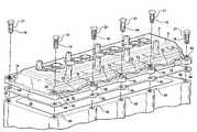
- FIG. 1is an exploded perspective view of flanged cover and spring retainer of the invention
- FIG. 2is an enlargement of a portion of FIG. 1 .
- FIG. 3Ais a partially exploded section view of the flanged cover and spring assembly of FIG. 1 ;
- FIG. 3Bis a assembled section view of the elements of FIG. 3A ;
- FIG. 4Ais a partially exploded section view of a second embodiment of the flanged cover and spring assembly of the present invention.
- FIG. 4Bis an assembled section view of the elements of FIG. 4A ;
- FIG. 5Ais an exploded section view of a third embodiment of flanged cover and spring assembly of the present invention.
- FIG. 5Bis a partially assembled section view of the elements of FIG. 5A ;
- FIG. 6Ais an exploded section view of a fourth embodiment of an assembly of the present invention.
- FIG. 6Bis a partially assembled section view of the elements of FIG. 6A .
- FIG. 7Ais an exploded view of a fifth embodiment of an assembly of the present invention.
- FIG. 7Bis an assembled section view of the elements of FIG. 7A .
- Flanged cover assemblyincludes a cover 4 .
- Cover 4has a wall portion 6 that is designed to cover or enclose a predetermined space, such as the space above the valves of an internal combustion engine which is enclosed by a valve cover.
- Wall portion 6has a lateral attachment flange 8 which extends around its perimeter and extends outwardly therefrom.
- Lateral attachment flange 8may include a plurality of spaced flange bores 10 which extend through the lateral attachment flange 8 from a upper surface 12 to a lower surface 14 .
- Spaced flange bores 10are adapted to receive a means for attaching 21 cover 4 to a base 18 .
- the means for attaching 21may compromise a plurality of fasteners 16 which correspond to the number of spaced flange bores and are adapted to be inserted through the plurality of bores 10 and secure the cover 4 to a base 18 .
- Cover assembly 2may also include a spring retainer 20 which extends along at least a portion 22 of upper surface 12 of lateral attachment flange 8 .
- Spring retainer 20also may include a plurality of spaced retainer bores 24 corresponding to the spaced flange bores 10 and at least one shaped spring portion 25 that is adapted to contact upper surface 12 of the lateral attachment flange 8 mediate the spaced flange bores 10 and apply a spring force thereto.
- Cover assembly 2also may include cover gasket 26 .
- Cover gasket 26also may include a plurality of gasket bores 28 corresponding to the plurality of spaced flange bores 10 and spaced retainer bores 24 .
- the at least one shaped spring portion 25is adapted to apply a spring force to the lateral flange, in this case at upper surface 12 of the lateral attachment flange 8 , when a means for applying spring force 21 is applied to press the assembly together and form seal joint.
- Means for applying spring force 21may include any suitable means, including various types of clamping mechanisms which may be applied to clamp the spring retainer 20 to the lateral attachment flange 8 , and which may also be used clamp the spring retainer 20 and lateral attachment flange 8 to cover gasket 26 (if utilized) and base 18 .
- the meansmay include one or more of various types of threaded and unthreaded fasteners, such as threaded bolts, screws and cam surface fasteners.
- means for applying a spring forcemay comprise a plurality of threaded fasteners 16 , such as threaded bolts, which are inserted through a plurality of spaced spring retainer bores 24 and the plurality of spaced flange bores 10 and tightened into a plurality of threaded bores 30 in the base 18 , such as the cylinder head of the engine, as shown in FIG. 3A .
- threaded fasteners 16such as threaded bolts
- spring retainer 20is pressed against the upper surface 12 of lateral attachment flange 8 thereby applying spring force to the flange in the region between or mediate spaced retainer bores 24 .
- the magnitude of the spring force appliedmay be varied by appropriate design of the spring retainer, including factors which may affect the spring force applied by the curved spring sections, such as selection of the spring material (particularly the modulus of elasticity), the thickness of the spring section, the degree of curvature of the spring and other known factors affecting the spring force.
- the spring forcemay be selected to ensure the sealing engagement of the flange and gasket against the sealing surface of base, such that the seal joint does not leak over the entire operating temperature and pressure range of the sealed joint.
- the spring forcemay be selected to make the sealing pressure applied to the gasket more uniform around the perimeter of the sealed joint, particularly in the regions between the fasteners.
- the spring forcemay also be selected to apply sufficient force to reduce or eliminate warping of the lateral attachment flange which would or could otherwise occur in these regions.
- the cover 4may be formed from any suitable cover material, including various metals and plastics. If cover 4 is a metal, it preferably will have a high degree of castability or formability.
- Cover 4may comprise an engineering plastic material, such as an engineering thermoplastic material or an engineering thermoset material. Examples include: acrylonitrile butadiene styrene (ABS), polyester, polyethylene (PEE), polyamide (PA), polyphenylene sulfide (PPS), polyphenylene ether (PPE), polybutylene terephthalate (PBT) polyethylene terephthalate (PET) and polyvinyl chloride. These may include both filled engineering plastics and unfilled engineering plastics as are well known.
- Cover 4may be formed using conventional forming methods, such as casting, stamping and drawing in the case of metal covers, and injection molding in the case of plastic materials.
- Cover 4may comprise a valve cover for covering and providing a sealed enclosure for the valve lifters, rocker arms and valves in the cylinder head of an internal combustion engine.
- Valve cover 4is preferably formed from an engineering plastic material that has high temperature dimensional stability, chemical resistance and other well-known features associated with automotive underhood applications.
- the covermay have a length (L) that is greater than the width (W), as illustrated in FIG. 1 , and a wall portion 6 that also defines the depth of the enclosure.
- Wall portion 6may include a lateral attachment flange 8 that extends laterally and outwardly from its periphery and is adapted for sealing engagement with gasket 26 or seal in order to seal cover 4 to base 18 , such as a cylinder head.
- Cover 4including wall portion 6 and lateral attachment flange 8 , and gasket 26 , may be of conventional design and construction.
- the spring retainer 20may be formed from any material with suitable physical properties, such as elastic modulus, that can be used to form a spring member. Examples of suitable materials include various forms of spring steel sheet and spring steel rod. Spring elements may be stamped and formed from spring steels sheet or bent or otherwise formed from spring steel rod. In the illustrated embodiment, spring member 20 comprises two spring elements 32 , one which extends along the rear of cover 4 and the other which extends along the front of cover 4 . Each element includes a plurality of curved spring portions 25 which are formed along its length. Spring retainer 20 may be formed as two elements 32 as shown, or as a single element which extends all the way around the perimeter of lateral attachment flange 8 , or as more than two elements. The elements may be separate as shown in FIG. 1 , or may be linked together as by connecting two elements with a single fastener.
- suitable materialsinclude various forms of spring steel sheet and spring steel rod.
- Spring elementsmay be stamped and formed from spring steels sheet or bent or otherwise formed from spring steel rod.
- spring member 20comprises two
- Base 18may be of conventional construction.
- Cover gasket 26may also be of conventional construction.
- Means for attachment 21such as fastener 16 , may also be of conventional construction.
- FIGS. 4A and 4Billustrate a second embodiment of the invention.
- FIG. 4Ashows the cover assembly elements in the unassembled condition.
- FIG. 4Bshows the cover assembly elements in the assembled condition.
- the embodimentis similar to the first embodiment, but includes a different construction of spring element 20 .
- spring element 20includes a travel stop, drive stop or limiter 34 .
- the height of travel stop 34can be selected so as to prevent fastener 16 from being overtightened and damaging spring element 20 , attachment flange 8 or cover gasket 26 .
- Flange bores 10 and cover gasket bores 28may also be adapted to receive the travel stop 34 .
- FIGS. 5A and 5Billustrate a third embodiment of the invention.
- FIG. 5Ashows the cover assembly elements in the unassembled condition.
- FIG. 5Bshows the cover assembly elements in the partially assembled condition.
- cover 4includes a plurality of spring retention features 36 .
- Spring retention features 36are in the form of spring bore bosses 38 having a corresponding plurality of lateral slots 40 that are adapted to receive and retain the spring elements 32 .
- Spring bore bosses 38 and lateral slots 40are designed to retain spring elements 32 with spring portions 25 compressed against lateral attachment flange 8 as shown in FIG. 5B .
- boltsare not used to compress spring portions 26 .
- This embodimenthas the advantage of permitting the preassembly of the spring elements to the cover.
- FIGS. 6A and 6Billustrate a fourth embodiment of the invention.
- FIG. 6Ashows the cover assembly elements in the unassembled condition.
- FIG. 6Bshows the cover assembly elements in the partially assembled condition.
- spring portions 25 of spring elements 20are precompressed and molded into lateral attachment flange 8 of cover 6 .
- the precompressed springsexert spring force within a mid-plane within lateral attachment flange 8 and produce an internal stress within the flange that is greater at the locations between the flange bores and lesser at the flange bores.
- FIGS. 7A and 7Billustrate another embodiment of the invention.
- FIG. 7Ashows the cover assembly elements in the unassembled condition.
- FIG. 7Bshows the cover assembly elements in the assembled condition.
- This embodimentis similar to the embodiment illustrated in FIGS. 3A and 3B , but including an elastomer layer 48 that is incorporated between spring element 20 and attachment flange 8 .
- Elastomer layer 48may be bonded to spring element 20 , but may alternately be incorporated as a discrete element or layer.
- Elastomer layer 48may comprise a natural or synthetic rubber, but any elastomer compatible with the intended application and application environment may be used.
- Elastomer layer 48provides vibration damping between spring element 20 and attachment flange 8 .
- Elastomer layer 48may also be similarly incorporated into any of the other embodiments described herein to similarly provide vibration damping with respect to spring element 20 and flange cover 8 .
Landscapes
- Engineering & Computer Science (AREA)
- Mechanical Engineering (AREA)
- General Engineering & Computer Science (AREA)
- Chemical & Material Sciences (AREA)
- Combustion & Propulsion (AREA)
- Cylinder Crankcases Of Internal Combustion Engines (AREA)
- Gasket Seals (AREA)
- Pressure Vessels And Lids Thereof (AREA)
Abstract
Description
Claims (27)
Priority Applications (9)
| Application Number | Priority Date | Filing Date | Title |
|---|---|---|---|
| US11/251,950US7255079B2 (en) | 2004-10-18 | 2005-10-17 | Flanged cover assembly with flange pressure distribution compensator |
| CN2005800430780ACN101080554B (en) | 2004-10-18 | 2005-10-18 | Flange cover assembly with flange pressure distribution compensation |
| JP2007537036AJP4866857B2 (en) | 2004-10-18 | 2005-10-18 | Cover assembly |
| MX2007004508AMX2007004508A (en) | 2004-10-18 | 2005-10-18 | Flanged cover assembly with flange pressure distribution compensator. |
| PCT/US2005/037677WO2006044999A2 (en) | 2004-10-18 | 2005-10-18 | Flanged cover assembly with flange pressure distribution compensator |
| KR1020077010327AKR101195813B1 (en) | 2004-10-18 | 2005-10-18 | Flanged cover assembly with flange pressure distribution compensator |
| EP05813974AEP1802861A2 (en) | 2004-10-18 | 2005-10-18 | Flanged cover assembly with flange pressure distribution compensator |
| BRPI0516615-2ABRPI0516615A (en) | 2004-10-18 | 2005-10-18 | flanged top assembly with flange pressure distribution compensator |
| JP2011177513AJP2011247271A (en) | 2004-10-18 | 2011-08-15 | Cover assembly |
Applications Claiming Priority (3)
| Application Number | Priority Date | Filing Date | Title |
|---|---|---|---|
| US61986504P | 2004-10-18 | 2004-10-18 | |
| US63166804P | 2004-11-30 | 2004-11-30 | |
| US11/251,950US7255079B2 (en) | 2004-10-18 | 2005-10-17 | Flanged cover assembly with flange pressure distribution compensator |
Publications (2)
| Publication Number | Publication Date |
|---|---|
| US20060144358A1 US20060144358A1 (en) | 2006-07-06 |
| US7255079B2true US7255079B2 (en) | 2007-08-14 |
Family
ID=36203689
Family Applications (1)
| Application Number | Title | Priority Date | Filing Date |
|---|---|---|---|
| US11/251,950Expired - Fee RelatedUS7255079B2 (en) | 2004-10-18 | 2005-10-17 | Flanged cover assembly with flange pressure distribution compensator |
Country Status (8)
| Country | Link |
|---|---|
| US (1) | US7255079B2 (en) |
| EP (1) | EP1802861A2 (en) |
| JP (2) | JP4866857B2 (en) |
| KR (1) | KR101195813B1 (en) |
| CN (1) | CN101080554B (en) |
| BR (1) | BRPI0516615A (en) |
| MX (1) | MX2007004508A (en) |
| WO (1) | WO2006044999A2 (en) |
Cited By (3)
| Publication number | Priority date | Publication date | Assignee | Title |
|---|---|---|---|---|
| US20110100320A1 (en)* | 2009-11-03 | 2011-05-05 | Ernst Gregory R | Engine dust and dirt shield or cover |
| US20220412285A1 (en)* | 2019-12-24 | 2022-12-29 | Fleetguard Filters Private Limited | Cylinder cover for internal combustion engine |
| US20240109410A1 (en)* | 2022-10-03 | 2024-04-04 | Dana Heavy Vehicle Systems Group, Llc | Systems for a coupling device |
Families Citing this family (6)
| Publication number | Priority date | Publication date | Assignee | Title |
|---|---|---|---|---|
| DE102006048176A1 (en)* | 2006-10-10 | 2008-04-17 | Mahle International Gmbh | Piston engine for vehicles has cylindrical head with cylindrical head covering, which is mounted at multiple singular mounting positions on cylindrical head |
| JP5238990B2 (en)* | 2007-12-07 | 2013-07-17 | 豊田合成株式会社 | Soundproof cover for automobile parts |
| DE102011116934A1 (en)* | 2011-10-26 | 2013-05-02 | Man Truck & Bus Ag | Arrangement of a valve cover on the cylinder head of an internal combustion engine |
| US8967110B2 (en)* | 2012-11-16 | 2015-03-03 | GM Global Technology Operations LLC | Engine front cover with rotational support insert |
| FR3039211B1 (en)* | 2015-07-21 | 2019-07-26 | Safran Aircraft Engines | COMPRESSION DEVICE FOR IMPROVING THE SEAL BETWEEN A TURBOMACHINE COVER AND A BEARING SUPPORT PART |
| WO2021130725A1 (en)* | 2019-12-24 | 2021-07-01 | Fleetguard Filters Private Limited | Cylinder cover for internal combustion engine |
Citations (14)
| Publication number | Priority date | Publication date | Assignee | Title |
|---|---|---|---|---|
| US2877756A (en) | 1958-03-14 | 1959-03-17 | Mccauley Norman | Overhead valve cover hold-down device |
| US4067531A (en) | 1976-07-22 | 1978-01-10 | Derre & Company | Vibration isolation and sealing gasket |
| US4394853A (en) | 1981-06-22 | 1983-07-26 | General Motors Corporation | Engine oil pan isolation mounting |
| US4456268A (en) | 1982-09-30 | 1984-06-26 | Allis-Chalmers Corp. | Fastening means in sealed gasket assembly including shoulder bolt |
| US4492189A (en) | 1981-07-16 | 1985-01-08 | Nissan Motor Company, Ltd. | Rocker cover assembly |
| US4522165A (en) | 1979-06-02 | 1985-06-11 | Nissan Motor Company, Limited | Noise reducing cover for an internal combustion engine |
| US4548170A (en) | 1983-04-27 | 1985-10-22 | Steyr-Daimler-Puch Aktiengesellschaft | Longitudinal housing wall of an internal combustion engine |
| US4821699A (en) | 1988-02-08 | 1989-04-18 | Alan Mackin | Pressure distribution device for valve cover |
| US4881595A (en)* | 1987-09-30 | 1989-11-21 | Sueddeutsche Kuehlerfabrik Julius Fr. Behr Gmbh & Co. Kg | Clamping connection |
| US4997193A (en) | 1990-05-18 | 1991-03-05 | Fel-Pro Incorporated | Oil pan gasket and method of making same |
| US5365901A (en)* | 1993-11-15 | 1994-11-22 | Freudenberg-Nok General Partnership | Low creep flange and engine cover assembly |
| US5639103A (en) | 1991-09-13 | 1997-06-17 | Meillor S.A. | Flat gasket, in particular for an internal combustion engine and related manufacturing method |
| US5655489A (en)* | 1994-09-27 | 1997-08-12 | Bayer Aktiengesellschaft | Valve cover |
| US6834741B2 (en)* | 2003-03-24 | 2004-12-28 | General Motors Corporation | Engine cover with internal vibration damping plates |
Family Cites Families (8)
| Publication number | Priority date | Publication date | Assignee | Title |
|---|---|---|---|---|
| US4571133A (en)* | 1984-07-23 | 1986-02-18 | General Motors Corporation | Loading washer assembly |
| JPS6256746U (en)* | 1985-09-27 | 1987-04-08 | ||
| GB8627374D0 (en)* | 1986-11-15 | 1986-12-17 | Renishaw Plc | Checking setting of tool |
| JPH0417801Y2 (en)* | 1987-02-26 | 1992-04-21 | ||
| JPH0283353A (en)* | 1988-09-16 | 1990-03-23 | Idemitsu Kosan Co Ltd | Aromatic compounds and their production methods |
| JPH0283353U (en)* | 1988-12-19 | 1990-06-27 | ||
| US5397206A (en)* | 1994-03-15 | 1995-03-14 | Chrysler Corporation | Vibration isolating fastener |
| JP2001152966A (en)* | 1999-11-30 | 2001-06-05 | Pacific Ind Co Ltd | Resin cylinder head cover |
- 2005
- 2005-10-17USUS11/251,950patent/US7255079B2/ennot_activeExpired - Fee Related
- 2005-10-18JPJP2007537036Apatent/JP4866857B2/ennot_activeExpired - Fee Related
- 2005-10-18EPEP05813974Apatent/EP1802861A2/ennot_activeWithdrawn
- 2005-10-18WOPCT/US2005/037677patent/WO2006044999A2/enactiveApplication Filing
- 2005-10-18BRBRPI0516615-2Apatent/BRPI0516615A/ennot_activeIP Right Cessation
- 2005-10-18MXMX2007004508Apatent/MX2007004508A/enactiveIP Right Grant
- 2005-10-18KRKR1020077010327Apatent/KR101195813B1/ennot_activeExpired - Fee Related
- 2005-10-18CNCN2005800430780Apatent/CN101080554B/ennot_activeExpired - Fee Related
- 2011
- 2011-08-15JPJP2011177513Apatent/JP2011247271A/enactivePending
Patent Citations (14)
| Publication number | Priority date | Publication date | Assignee | Title |
|---|---|---|---|---|
| US2877756A (en) | 1958-03-14 | 1959-03-17 | Mccauley Norman | Overhead valve cover hold-down device |
| US4067531A (en) | 1976-07-22 | 1978-01-10 | Derre & Company | Vibration isolation and sealing gasket |
| US4522165A (en) | 1979-06-02 | 1985-06-11 | Nissan Motor Company, Limited | Noise reducing cover for an internal combustion engine |
| US4394853A (en) | 1981-06-22 | 1983-07-26 | General Motors Corporation | Engine oil pan isolation mounting |
| US4492189A (en) | 1981-07-16 | 1985-01-08 | Nissan Motor Company, Ltd. | Rocker cover assembly |
| US4456268A (en) | 1982-09-30 | 1984-06-26 | Allis-Chalmers Corp. | Fastening means in sealed gasket assembly including shoulder bolt |
| US4548170A (en) | 1983-04-27 | 1985-10-22 | Steyr-Daimler-Puch Aktiengesellschaft | Longitudinal housing wall of an internal combustion engine |
| US4881595A (en)* | 1987-09-30 | 1989-11-21 | Sueddeutsche Kuehlerfabrik Julius Fr. Behr Gmbh & Co. Kg | Clamping connection |
| US4821699A (en) | 1988-02-08 | 1989-04-18 | Alan Mackin | Pressure distribution device for valve cover |
| US4997193A (en) | 1990-05-18 | 1991-03-05 | Fel-Pro Incorporated | Oil pan gasket and method of making same |
| US5639103A (en) | 1991-09-13 | 1997-06-17 | Meillor S.A. | Flat gasket, in particular for an internal combustion engine and related manufacturing method |
| US5365901A (en)* | 1993-11-15 | 1994-11-22 | Freudenberg-Nok General Partnership | Low creep flange and engine cover assembly |
| US5655489A (en)* | 1994-09-27 | 1997-08-12 | Bayer Aktiengesellschaft | Valve cover |
| US6834741B2 (en)* | 2003-03-24 | 2004-12-28 | General Motors Corporation | Engine cover with internal vibration damping plates |
Cited By (5)
| Publication number | Priority date | Publication date | Assignee | Title |
|---|---|---|---|---|
| US20110100320A1 (en)* | 2009-11-03 | 2011-05-05 | Ernst Gregory R | Engine dust and dirt shield or cover |
| US8833336B2 (en)* | 2009-11-03 | 2014-09-16 | Gregory R. Ernst | Engine dust and dirt shield or cover |
| US20220412285A1 (en)* | 2019-12-24 | 2022-12-29 | Fleetguard Filters Private Limited | Cylinder cover for internal combustion engine |
| US11661904B2 (en)* | 2019-12-24 | 2023-05-30 | Fleetguard Filters Private Limited | Cylinder cover for internal combustion engine |
| US20240109410A1 (en)* | 2022-10-03 | 2024-04-04 | Dana Heavy Vehicle Systems Group, Llc | Systems for a coupling device |
Also Published As
| Publication number | Publication date |
|---|---|
| BRPI0516615A (en) | 2008-09-16 |
| US20060144358A1 (en) | 2006-07-06 |
| JP4866857B2 (en) | 2012-02-01 |
| CN101080554B (en) | 2012-12-12 |
| JP2008517204A (en) | 2008-05-22 |
| KR101195813B1 (en) | 2012-11-05 |
| CN101080554A (en) | 2007-11-28 |
| WO2006044999A2 (en) | 2006-04-27 |
| EP1802861A2 (en) | 2007-07-04 |
| MX2007004508A (en) | 2007-06-14 |
| KR20070072910A (en) | 2007-07-06 |
| JP2011247271A (en) | 2011-12-08 |
| WO2006044999A3 (en) | 2006-10-26 |
Similar Documents
| Publication | Publication Date | Title |
|---|---|---|
| JP2011247271A (en) | Cover assembly | |
| US5428895A (en) | Method of manufacturing sealing gasket with hard interior backbone and integral crush limiters | |
| US4535999A (en) | Gasket assembly having a sealing member suspended in a clear-through opening and method of making same | |
| US6039323A (en) | Rubber molded gasket with compression limiter | |
| US7827950B2 (en) | Valve cover assembly and method of construction | |
| US7771641B2 (en) | Component part with integrated seal | |
| US6994354B2 (en) | Vibrationally decoupling gasket | |
| EP1610042A1 (en) | Elastomer coated screen gasket | |
| EP0494489B1 (en) | Metallic gasket | |
| US7004477B2 (en) | Reduced load gasket | |
| US7234705B2 (en) | Sealing gasket with flexible stopper | |
| US6089573A (en) | Metal gasket with corrugated bead | |
| US6164662A (en) | Metal gasket | |
| US5275420A (en) | End seals for V-type internal combustion engines and engine sealing method | |
| EP1510735A2 (en) | Sealing gasket with flexible stopper | |
| EP0552948A1 (en) | A protecting member for a gasket | |
| EP0486255B1 (en) | Metallic gasket | |
| US20050046120A1 (en) | Sealing gasket with flexible stopper | |
| US6848690B1 (en) | Seal for head gaskets of internal combustion engines | |
| US7040268B1 (en) | Engine cover brace assembly | |
| JP2003201929A (en) | Carrier gasket | |
| JP3574748B2 (en) | Intake manifold gasket | |
| US8789831B2 (en) | Compression limiter with molded insert for gaskets | |
| JP3467062B2 (en) | Metal gasket | |
| JP3564924B2 (en) | Anti-vibration gasket and manufacturing method thereof |
Legal Events
| Date | Code | Title | Description |
|---|---|---|---|
| AS | Assignment | Owner name:FEDERAL-MOGUL WORLD WIDE, INC., MICHIGAN Free format text:ASSIGNMENT OF ASSIGNORS INTEREST;ASSIGNORS:TRIPATHY, BHAWANI S.;SEDLAR, BRENT R.;REEL/FRAME:017335/0527 Effective date:20060307 | |
| AS | Assignment | Owner name:CITIBANK, N.A. AS COLLATERAL TRUSTEE, NEW YORK Free format text:SECURITY AGREEMENT;ASSIGNOR:FEDERAL-MOGUL WORLD WIDE, INC.;REEL/FRAME:020362/0139 Effective date:20071227 Owner name:CITIBANK, N.A. AS COLLATERAL TRUSTEE,NEW YORK Free format text:SECURITY AGREEMENT;ASSIGNOR:FEDERAL-MOGUL WORLD WIDE, INC.;REEL/FRAME:020362/0139 Effective date:20071227 | |
| FPAY | Fee payment | Year of fee payment:4 | |
| AS | Assignment | Owner name:CITIBANK, N.A., AS COLLATERAL TRUSTEE, DELAWARE Free format text:SECURITY INTEREST;ASSIGNORS:FEDERAL-MOGUL CORPORATION, A DELAWARE CORPORATION;FEDERAL-MOGUL WORLD WIDE, INC., A MICHIGAN CORPORATION;FEDERAL-MOGUL IGNITION COMPANY, A DELAWARE CORPORATION;AND OTHERS;REEL/FRAME:033204/0707 Effective date:20140616 | |
| REMI | Maintenance fee reminder mailed | ||
| LAPS | Lapse for failure to pay maintenance fees | ||
| STCH | Information on status: patent discontinuation | Free format text:PATENT EXPIRED DUE TO NONPAYMENT OF MAINTENANCE FEES UNDER 37 CFR 1.362 | |
| FP | Lapsed due to failure to pay maintenance fee | Effective date:20150814 | |
| AS | Assignment | Owner name:FEDERAL-MOGUL WORLD WIDE LLC (FORMERLY FEDERAL-MOGUL WORLD WIDE, INC.), MICHIGAN Free format text:RELEASE BY SECURED PARTY;ASSIGNOR:CITIBANK, N.A.;REEL/FRAME:062389/0149 Effective date:20230112 |