US7254947B2 - Vehicle cooling system - Google Patents
Vehicle cooling systemDownload PDFInfo
- Publication number
- US7254947B2 US7254947B2US11/149,761US14976105AUS7254947B2US 7254947 B2US7254947 B2US 7254947B2US 14976105 AUS14976105 AUS 14976105AUS 7254947 B2US7254947 B2US 7254947B2
- Authority
- US
- United States
- Prior art keywords
- air
- cooler
- radiator
- cooling
- primary
- Prior art date
- Legal status (The legal status is an assumption and is not a legal conclusion. Google has not performed a legal analysis and makes no representation as to the accuracy of the status listed.)
- Expired - Lifetime
Links
Images

Classifications
- F—MECHANICAL ENGINEERING; LIGHTING; HEATING; WEAPONS; BLASTING
- F02—COMBUSTION ENGINES; HOT-GAS OR COMBUSTION-PRODUCT ENGINE PLANTS
- F02B—INTERNAL-COMBUSTION PISTON ENGINES; COMBUSTION ENGINES IN GENERAL
- F02B29/00—Engines characterised by provision for charging or scavenging not provided for in groups F02B25/00, F02B27/00 or F02B33/00 - F02B39/00; Details thereof
- F02B29/04—Cooling of air intake supply
- F02B29/0406—Layout of the intake air cooling or coolant circuit
- F02B29/0437—Liquid cooled heat exchangers
- F02B29/0443—Layout of the coolant or refrigerant circuit
- F—MECHANICAL ENGINEERING; LIGHTING; HEATING; WEAPONS; BLASTING
- F02—COMBUSTION ENGINES; HOT-GAS OR COMBUSTION-PRODUCT ENGINE PLANTS
- F02M—SUPPLYING COMBUSTION ENGINES IN GENERAL WITH COMBUSTIBLE MIXTURES OR CONSTITUENTS THEREOF
- F02M26/00—Engine-pertinent apparatus for adding exhaust gases to combustion-air, main fuel or fuel-air mixture, e.g. by exhaust gas recirculation [EGR] systems
- F02M26/13—Arrangement or layout of EGR passages, e.g. in relation to specific engine parts or for incorporation of accessories
- F02M26/22—Arrangement or layout of EGR passages, e.g. in relation to specific engine parts or for incorporation of accessories with coolers in the recirculation passage
- F02M26/23—Layout, e.g. schematics
- F02M26/28—Layout, e.g. schematics with liquid-cooled heat exchangers
- F—MECHANICAL ENGINEERING; LIGHTING; HEATING; WEAPONS; BLASTING
- F01—MACHINES OR ENGINES IN GENERAL; ENGINE PLANTS IN GENERAL; STEAM ENGINES
- F01P—COOLING OF MACHINES OR ENGINES IN GENERAL; COOLING OF INTERNAL-COMBUSTION ENGINES
- F01P2060/00—Cooling circuits using auxiliaries
- F01P2060/02—Intercooler
- F—MECHANICAL ENGINEERING; LIGHTING; HEATING; WEAPONS; BLASTING
- F01—MACHINES OR ENGINES IN GENERAL; ENGINE PLANTS IN GENERAL; STEAM ENGINES
- F01P—COOLING OF MACHINES OR ENGINES IN GENERAL; COOLING OF INTERNAL-COMBUSTION ENGINES
- F01P2060/00—Cooling circuits using auxiliaries
- F01P2060/04—Lubricant cooler
- F01P2060/045—Lubricant cooler for transmissions
- F—MECHANICAL ENGINEERING; LIGHTING; HEATING; WEAPONS; BLASTING
- F01—MACHINES OR ENGINES IN GENERAL; ENGINE PLANTS IN GENERAL; STEAM ENGINES
- F01P—COOLING OF MACHINES OR ENGINES IN GENERAL; COOLING OF INTERNAL-COMBUSTION ENGINES
- F01P7/00—Controlling of coolant flow
- F01P7/14—Controlling of coolant flow the coolant being liquid
- F01P7/16—Controlling of coolant flow the coolant being liquid by thermostatic control
- F01P7/165—Controlling of coolant flow the coolant being liquid by thermostatic control characterised by systems with two or more loops
- F—MECHANICAL ENGINEERING; LIGHTING; HEATING; WEAPONS; BLASTING
- F02—COMBUSTION ENGINES; HOT-GAS OR COMBUSTION-PRODUCT ENGINE PLANTS
- F02B—INTERNAL-COMBUSTION PISTON ENGINES; COMBUSTION ENGINES IN GENERAL
- F02B29/00—Engines characterised by provision for charging or scavenging not provided for in groups F02B25/00, F02B27/00 or F02B33/00 - F02B39/00; Details thereof
- F02B29/04—Cooling of air intake supply
- F02B29/0406—Layout of the intake air cooling or coolant circuit
- F02B29/0412—Multiple heat exchangers arranged in parallel or in series
- F—MECHANICAL ENGINEERING; LIGHTING; HEATING; WEAPONS; BLASTING
- F02—COMBUSTION ENGINES; HOT-GAS OR COMBUSTION-PRODUCT ENGINE PLANTS
- F02B—INTERNAL-COMBUSTION PISTON ENGINES; COMBUSTION ENGINES IN GENERAL
- F02B29/00—Engines characterised by provision for charging or scavenging not provided for in groups F02B25/00, F02B27/00 or F02B33/00 - F02B39/00; Details thereof
- F02B29/04—Cooling of air intake supply
- F02B29/0406—Layout of the intake air cooling or coolant circuit
- F02B29/0425—Air cooled heat exchangers
- F—MECHANICAL ENGINEERING; LIGHTING; HEATING; WEAPONS; BLASTING
- F02—COMBUSTION ENGINES; HOT-GAS OR COMBUSTION-PRODUCT ENGINE PLANTS
- F02B—INTERNAL-COMBUSTION PISTON ENGINES; COMBUSTION ENGINES IN GENERAL
- F02B37/00—Engines characterised by provision of pumps driven at least for part of the time by exhaust
- F—MECHANICAL ENGINEERING; LIGHTING; HEATING; WEAPONS; BLASTING
- F02—COMBUSTION ENGINES; HOT-GAS OR COMBUSTION-PRODUCT ENGINE PLANTS
- F02M—SUPPLYING COMBUSTION ENGINES IN GENERAL WITH COMBUSTIBLE MIXTURES OR CONSTITUENTS THEREOF
- F02M26/00—Engine-pertinent apparatus for adding exhaust gases to combustion-air, main fuel or fuel-air mixture, e.g. by exhaust gas recirculation [EGR] systems
- F02M26/02—EGR systems specially adapted for supercharged engines
- F02M26/04—EGR systems specially adapted for supercharged engines with a single turbocharger
- F02M26/05—High pressure loops, i.e. wherein recirculated exhaust gas is taken out from the exhaust system upstream of the turbine and reintroduced into the intake system downstream of the compressor
- Y—GENERAL TAGGING OF NEW TECHNOLOGICAL DEVELOPMENTS; GENERAL TAGGING OF CROSS-SECTIONAL TECHNOLOGIES SPANNING OVER SEVERAL SECTIONS OF THE IPC; TECHNICAL SUBJECTS COVERED BY FORMER USPC CROSS-REFERENCE ART COLLECTIONS [XRACs] AND DIGESTS
- Y02—TECHNOLOGIES OR APPLICATIONS FOR MITIGATION OR ADAPTATION AGAINST CLIMATE CHANGE
- Y02T—CLIMATE CHANGE MITIGATION TECHNOLOGIES RELATED TO TRANSPORTATION
- Y02T10/00—Road transport of goods or passengers
- Y02T10/10—Internal combustion engine [ICE] based vehicles
- Y02T10/12—Improving ICE efficiencies
Definitions
- the present inventionrelates to a cooling system for a vehicle.
- cooling systemsbecome more effective and more heat is transferred as the temperature difference increases between the fluid being cooled and the coolant. It is also known that cooling systems naturally operate at higher temperatures when handling higher heat loads. But, an engine can be damaged or will operate poorly if the engine receives coolant fluid which becomes too hot.
- Some heat sources in a tractorare hotter than the engine block and head cooling circuit. In some cooling systems, such sources are cooled by the coolant used for engine block cooling, thus requiring a larger radiator than would be needed to cool only the engine. But, the amount of additional heat may not justify a separate high temperature cooling circuit.
- Tier III engine emission regulationswill require the cooling of yet another high temperature heat source—exhaust gas recirculation or EGR.
- EGR coolinginvolves adding some cooled inert exhaust gas to the fresh air supplied to the engine to increase the mass of air in the cylinder. This reduces the maximum temperature in the combustion process, and thereby reduces the amount of NOX produced as a unwanted byproduct.
- C-EGRCooled—Exhaust Gas recirculation
- tier 3 engine emission requirementshas added a high temperature heat source. This, combined with some other current high temperature heat sources, can make a higher temperature circuit practical. Two of the current higher temperature heat sources are the engine oil and the partial cooling of the charge air.
- a vehicle engine cooling systemincludes a primary cooling circuit having a primary radiator and a coolant pump for circulating coolant through the engine and the primary radiator.
- a secondary cooling circuitincludes a secondary radiator and one or more coolers for cooling a high temperature heat source, such as exhaust gas recirculation (EGR) cooler, and/or a liquid/air charge air pre-cooler receiving engine inlet air from a turbocharger compressor.
- the coolant pumpcirculates coolant through the EGR cooler and/or through the charge air pre-cooler, and through the secondary radiator.
- a fanblows cooling air through the primary radiator and the secondary radiator.
- the secondary radiatoris preferably downstream of the primary radiator with respect to flow of cooling air.
- the cooling systemmay also include an air-to-air charge air cooler which receives engine inlet air from the liquid/air charge air pre-cooler.
- the air-to-air charge air cooleris preferably upstream of the primary radiator with respect to flow of cooling air.
- the cooling systemalso includes an auxiliary engine fluid cooler which is located between the air-to-air charge air cooler and the primary radiator.
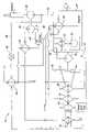
- the sole FIGUREis a schematic diagram of a vehicle cooling system according to the invention.
- the cooling system 10includes an engine cooling circuit 12 which includes a primary or standard radiator 14 , a fan 16 and a coolant pump 18 , both driven by the engine 20 .
- Radiator 14receives hot coolant (such as at 98 degrees C.) from the engine 20 and directs cooled coolant (such as at 92 degrees C.) back to an inlet of coolant pump 18 .
- the pump 18pumps coolant through the engine cooling passages 22 and back to radiator 14 .
- the pump 18also pumps coolant through engine oil cooling passages 24 and an EGR cooler 26 and then to an inlet of an additional or secondary high temperature radiator 28 and then back to an inlet of primary radiator 14 .
- the oil cooling passages 24 in the engine 20receive oil from a conventional engine oil pump 30 .
- the pump 18also pumps coolant through a passage 32 in the engine 20 , through a charge air cooler 34 and then back to the inlet of secondary radiator 28 .
- a conventional turbo-compressor 36includes a turbine 38 and a compressor 39 .
- Exhaust gasis communicated from the engine 20 through exhaust line 40 to the turbine 38 of turbo-compressor 36 .
- An EGR line 46communicates EGR from exhaust line 40 through EGR valve 48 and preferably to EGR cooler 26 , then to engine air intake 27 .
- Intake airis received by air cleaner 52 , compressed by compressor 39 , then preferably cooled by charge air pre-cooler 34 , further preferably cooled by an air-to-air charge air cooler 50 , then directed to engine air intake 27 .
- the systemmay also include an auxiliary oil cooler 54 for cooling fluid such as transmission fluid, hydraulic fluid or fuel.
- coolers 50 , 54 , 14 and 28are arranged in series with respect to air blown by fan 16 so that air pulled by fan 16 passes first (at a temperature of approximately 25 degrees C.) through air-to-air charge air cooler 50 , then auxiliary cooler 54 , then primary radiator 14 and finally high temperature radiator 28 , (after which the air is at a temperature of approximately 80 degrees C.).
- the radiator 28can be considered as an intermediate cooler which receives heat from high temperature heat sources including charge air cooler 34 and EGR cooler 26 .
- the heated coolant from radiator 28is combined with coolant from the engine 20 and supplied to an inlet of primary radiator 14 .
- high temperature radiator 28is downstream of primary radiator with respect to cooling airflow, and radiator 28 pre-cools coolant before the coolant is supplied to the primary radiator 14 .
- the system 10can be described as having a lower temperature primary cooling circuit including primary radiator 14 , coolant pump 18 and engine coolant passages 22 , and as having a higher temperature secondary cooling circuit including secondary radiator 28 , coolant pump 18 and coolers 26 and/or 34 .
- the coolingcan be done with smaller cooling parts and with a reduced amount of air moved by the fan because the high temperature coolant can exchange it's heat into the air already being moved by the fan, thus increasing the final temperature of the cooling air.
- the cooling airhas a typical temperature rise today of 40 degrees C. This secondary cooling circuit can increase this by 15 to 55 degrees C. for a significant increase in heat rejection.
Landscapes
- Engineering & Computer Science (AREA)
- Chemical & Material Sciences (AREA)
- Combustion & Propulsion (AREA)
- Mechanical Engineering (AREA)
- General Engineering & Computer Science (AREA)
- Physics & Mathematics (AREA)
- Thermal Sciences (AREA)
- Exhaust-Gas Circulating Devices (AREA)
Abstract
Description
The present invention relates to a cooling system for a vehicle.
It is known that cooling systems become more effective and more heat is transferred as the temperature difference increases between the fluid being cooled and the coolant. It is also known that cooling systems naturally operate at higher temperatures when handling higher heat loads. But, an engine can be damaged or will operate poorly if the engine receives coolant fluid which becomes too hot.
Some heat sources in a tractor are hotter than the engine block and head cooling circuit. In some cooling systems, such sources are cooled by the coolant used for engine block cooling, thus requiring a larger radiator than would be needed to cool only the engine. But, the amount of additional heat may not justify a separate high temperature cooling circuit.
In the future, Tier III engine emission regulations will require the cooling of yet another high temperature heat source—exhaust gas recirculation or EGR. EGR cooling involves adding some cooled inert exhaust gas to the fresh air supplied to the engine to increase the mass of air in the cylinder. This reduces the maximum temperature in the combustion process, and thereby reduces the amount of NOX produced as a unwanted byproduct.
The need for C-EGR (Cooled—Exhaust Gas recirculation) for tier3 engine emission requirements has added a high temperature heat source. This, combined with some other current high temperature heat sources, can make a higher temperature circuit practical. Two of the current higher temperature heat sources are the engine oil and the partial cooling of the charge air.
However, if the heat extracted from an EGR cooler were added to the basic engine cooling circuit, the cooling system components would have to be much larger and the power needed by the cooling fan would increase by possibly 50%.
Accordingly, an object of this invention is to provide a vehicle engine cooling system which includes EGR cooling without increasing the size of the basic engine cooling system components.
These and other objects are achieved by the present invention, wherein a vehicle engine cooling system includes a primary cooling circuit having a primary radiator and a coolant pump for circulating coolant through the engine and the primary radiator. A secondary cooling circuit includes a secondary radiator and one or more coolers for cooling a high temperature heat source, such as exhaust gas recirculation (EGR) cooler, and/or a liquid/air charge air pre-cooler receiving engine inlet air from a turbocharger compressor. The coolant pump circulates coolant through the EGR cooler and/or through the charge air pre-cooler, and through the secondary radiator. A fan blows cooling air through the primary radiator and the secondary radiator. The secondary radiator is preferably downstream of the primary radiator with respect to flow of cooling air. The cooling system may also include an air-to-air charge air cooler which receives engine inlet air from the liquid/air charge air pre-cooler. The air-to-air charge air cooler is preferably upstream of the primary radiator with respect to flow of cooling air. The cooling system also includes an auxiliary engine fluid cooler which is located between the air-to-air charge air cooler and the primary radiator.
The sole FIGURE is a schematic diagram of a vehicle cooling system according to the invention.
Referring to the FIGURE, thecooling system 10 includes anengine cooling circuit 12 which includes a primary orstandard radiator 14, afan 16 and acoolant pump 18, both driven by theengine 20.Radiator 14 receives hot coolant (such as at 98 degrees C.) from theengine 20 and directs cooled coolant (such as at 92 degrees C.) back to an inlet ofcoolant pump 18. Thepump 18 pumps coolant through theengine cooling passages 22 and back toradiator 14.
Thepump 18 also pumps coolant through engineoil cooling passages 24 and anEGR cooler 26 and then to an inlet of an additional or secondaryhigh temperature radiator 28 and then back to an inlet ofprimary radiator 14. Theoil cooling passages 24 in theengine 20 receive oil from a conventionalengine oil pump 30. Thepump 18 also pumps coolant through apassage 32 in theengine 20, through acharge air cooler 34 and then back to the inlet ofsecondary radiator 28.
A conventional turbo-compressor 36 includes aturbine 38 and acompressor 39. Exhaust gas is communicated from theengine 20 throughexhaust line 40 to theturbine 38 of turbo-compressor 36. An EGRline 46 communicates EGR fromexhaust line 40 throughEGR valve 48 and preferably to EGRcooler 26, then toengine air intake 27. Intake air is received byair cleaner 52, compressed bycompressor 39, then preferably cooled by charge air pre-cooler34, further preferably cooled by an air-to-aircharge air cooler 50, then directed toengine air intake 27.
The system may also include anauxiliary oil cooler 54 for cooling fluid such as transmission fluid, hydraulic fluid or fuel. Preferably,coolers fan 16 so that air pulled byfan 16 passes first (at a temperature of approximately 25 degrees C.) through air-to-aircharge air cooler 50, thenauxiliary cooler 54, thenprimary radiator 14 and finallyhigh temperature radiator 28, (after which the air is at a temperature of approximately 80 degrees C.).
As a result, in thesystem 10, theradiator 28 can be considered as an intermediate cooler which receives heat from high temperature heat sources includingcharge air cooler 34 and EGRcooler 26. The heated coolant fromradiator 28 is combined with coolant from theengine 20 and supplied to an inlet ofprimary radiator 14. Thus,high temperature radiator 28 is downstream of primary radiator with respect to cooling airflow, andradiator 28 pre-cools coolant before the coolant is supplied to theprimary radiator 14.
Thesystem 10 can be described as having a lower temperature primary cooling circuit includingprimary radiator 14,coolant pump 18 andengine coolant passages 22, and as having a higher temperature secondary cooling circuit includingsecondary radiator 28,coolant pump 18 andcoolers 26 and/or34.
By keeping the coolant temperature higher in the secondary cooling circuit, the cooling can be done with smaller cooling parts and with a reduced amount of air moved by the fan because the high temperature coolant can exchange it's heat into the air already being moved by the fan, thus increasing the final temperature of the cooling air. The cooling air has a typical temperature rise today of 40 degrees C. This secondary cooling circuit can increase this by 15 to 55 degrees C. for a significant increase in heat rejection.
While the present invention has been described in conjunction with a specific embodiment, it is understood that many alternatives, modifications and variations will be apparent to those skilled in the art in light of the foregoing description. Accordingly, this invention is intended to embrace all such alternatives, modifications and variations which fall within the spirit and scope of the appended claims.
Claims (12)
1. A vehicle engine cooling system:
a primary cooling circuit having a primary radiator, and a coolant pump for circulating coolant through the engine and the primary radiator;
a secondary cooling circuit having a secondary radiator and an exhaust gas recirculation (EGR) cooler, the coolant pump circulating coolant through the engine, the EGR cooler and the secondary radiator, the primary cooling circuit operating at a temperature which is lower than an operating temperature of the secondary cooling circuit; and
a fan for blowing cooling air through the primary radiator and the secondary radiator, the secondary radiator being downstream of the primary radiator with respect to flow of cooling air.
2. The cooling system ofclaim 1 , further comprising:
a liquid/air charge air pre-cooler receiving engine inlet air from a turbocharger compressor, the coolant pump circulating coolant through the charge air pre-cooler and through the secondary radiator.
3. The cooling system ofclaim 2 , further comprising:
an air-to-air charge air cooler, receiving engine inlet air from the liquid/air charge air pre-cooler, the air-to-air charge air cooler being upstream of the primary radiator with respect to flow of cooling air.
4. The cooling system ofclaim 3 , further comprising:
an auxiliary engine fluid cooler, the auxiliary cooler being between the air-to-air charge air cooler and the primary radiator with respect to flow of cooling air.
5. The cooling system ofclaim 1 , wherein:
the secondary radiator has a coolant outlet communicated with a coolant inlet of the primary radiator so that the primary radiator is directly downstream of the secondary radiator with respect to flow of coolant.
6. A vehicle engine cooling system:
a primary cooling circuit having a primary radiator and a coolant pump for circulating coolant through the engine and the primary radiator;
a secondary cooling circuit having a secondary radiator and an engine air cooler, the coolant pump circulating coolant through the engine, the engine air cooler and the secondary radiator, the primary cooling circuit operating at a temperature which is lower than an operating temperature of the secondary cooling circuit;
a liquid/air charge air pre-cooler receiving engine inlet air from a turbocharger compressor, the coolant pump circulating coolant through the charge air pre-cooler and through the secondary radiator; and
a fan for blowing cooling air through the primary radiator and the secondary radiator, the secondary radiator being downstream of the primary radiator with respect to flow of cooling air.
7. The cooling system ofclaim 6 , wherein:
the engine air cooler comprises a charge air pre-cooler.
8. The cooling system ofclaim 6 , further comprising:
an air-to-air charge air cooler, receiving engine inlet air from the liquid/air charge air pre-cooler, the air-to-air charge air cooler being upstream of the primary radiator with respect to flow of cooling air.
9. The cooling system ofclaim 8 , further comprising:
an auxiliary engine fluid cooler, the auxiliary cooler being between the air-to-air charge air cooler and the primary radiator with respect to flow of cooling air.
10. A vehicle engine cooling system:
a primary cooling circuit having a primary radiator, a coolant pump for circulating coolant through the engine and the primary radiator;
a secondary cooling circuit having a secondary radiator and an exhaust gas recirculation (EGR) cooler, the primary cooling circuit operating at a temperature which is lower than an operating temperature of the secondary cooling circuit;
a liquid/air charge air pre-cooler receiving engine inlet air from a turbocharger compressor, the coolant pump circulating coolant through the EGR cooler, through the charge air pre-cooler and through the secondary radiator; and
a fan for blowing cooling air through the primary radiator and the secondary radiator, the secondary radiator being downstream of the primary radiator with respect to flow of cooling air.
11. The cooling system ofclaim 10 , further comprising:
an air-to-air charge air cooler, receiving engine inlet air from the liquid/air charge air pre-cooler, the air-to-air charge air cooler being upstream of the primary radiator with respect to flow of cooling air.
12. The cooling system ofclaim 10 , further comprising:
an auxiliary engine fluid cooler, the auxiliary cooler being between the air-to-air charge air cooler and the primary radiator with respect to flow of cooling air.
Priority Applications (2)
| Application Number | Priority Date | Filing Date | Title |
|---|---|---|---|
| US11/149,761US7254947B2 (en) | 2005-06-10 | 2005-06-10 | Vehicle cooling system |
| DE102006024315.3ADE102006024315B4 (en) | 2005-06-10 | 2006-05-24 | Vehicle cooling system for a motor and an engine air cooler |
Applications Claiming Priority (1)
| Application Number | Priority Date | Filing Date | Title |
|---|---|---|---|
| US11/149,761US7254947B2 (en) | 2005-06-10 | 2005-06-10 | Vehicle cooling system |
Publications (2)
| Publication Number | Publication Date |
|---|---|
| US20060277906A1 US20060277906A1 (en) | 2006-12-14 |
| US7254947B2true US7254947B2 (en) | 2007-08-14 |
Family
ID=37522853
Family Applications (1)
| Application Number | Title | Priority Date | Filing Date |
|---|---|---|---|
| US11/149,761Expired - LifetimeUS7254947B2 (en) | 2005-06-10 | 2005-06-10 | Vehicle cooling system |
Country Status (2)
| Country | Link |
|---|---|
| US (1) | US7254947B2 (en) |
| DE (1) | DE102006024315B4 (en) |
Cited By (16)
| Publication number | Priority date | Publication date | Assignee | Title |
|---|---|---|---|---|
| US20070227141A1 (en)* | 2006-03-31 | 2007-10-04 | Jiubo Ma | Multi-stage jacket water aftercooler system |
| US20080047267A1 (en)* | 2004-05-28 | 2008-02-28 | Zoltan Kardos | Arrangement For Recirculation Of Exhaust Gases Of A Super-Charged Internal Combustion Engine |
| US20080053090A1 (en)* | 2004-05-28 | 2008-03-06 | Scania Cv Ab (Publ) | Arrangement for Recirculation of Exhaust Gases in a Super-Charged Internal Combustion Engine |
| US20080066697A1 (en)* | 2006-09-20 | 2008-03-20 | Man Nutzfahrzeuge Oesterreich Ag | Cooling system of an internal combustion engine having charge air feed |
| US20090188734A1 (en)* | 2008-01-30 | 2009-07-30 | Kevin Gordon Braun | Flow-Inducing Baffle For Engine Compartment Ventilation |
| US7717069B2 (en) | 2007-11-15 | 2010-05-18 | Caterpillar Inc. | Engine cooling system having two cooling circuits |
| US20100269800A1 (en)* | 2008-01-03 | 2010-10-28 | Mack Trucks, Inc. | Exhaust gas recirculation cooling circuit |
| US20110061744A1 (en)* | 2009-09-14 | 2011-03-17 | Jiffy-Tite Company, Inc. | Cooler bypass apparatus and installation kit |
| US20110139133A1 (en)* | 2010-05-28 | 2011-06-16 | Ford Global Technologies, Llc | Cooled egr system for coolant heating during cold engine start |
| JP2012506973A (en)* | 2008-11-05 | 2012-03-22 | スカニア シーブイ アクチボラグ | Cooling device for recirculated exhaust gas in a combustion engine |
| US20120067332A1 (en)* | 2010-09-17 | 2012-03-22 | Gm Global Technology Operations, Inc. | Integrated exhaust gas recirculation and charge cooling system |
| US20150107566A1 (en)* | 2012-05-16 | 2015-04-23 | Denso Corporation | Exhaust gas recirculation device |
| US20150219005A1 (en)* | 2014-01-31 | 2015-08-06 | Halla Visteon Climate Control Corp. | Method of improving charge air condition in air-cooled charge air coolers |
| US20170082014A1 (en)* | 2015-09-21 | 2017-03-23 | Hyundai Motor Company | Hybrid intercooler system using multiple cooling media and method of controlling the hybrid intercooler system using multiple cooling media |
| US10352229B2 (en) | 2017-12-18 | 2019-07-16 | Cnh Industrial America Llc | Cooling system for a work vehicle |
| US10550758B2 (en) | 2017-12-18 | 2020-02-04 | Cnh Industrial America Llc | Cooling system for a work vehicle |
Families Citing this family (29)
| Publication number | Priority date | Publication date | Assignee | Title |
|---|---|---|---|---|
| US10308265B2 (en) | 2006-03-20 | 2019-06-04 | Ge Global Sourcing Llc | Vehicle control system and method |
| US9233696B2 (en) | 2006-03-20 | 2016-01-12 | General Electric Company | Trip optimizer method, system and computer software code for operating a railroad train to minimize wheel and track wear |
| US9733625B2 (en) | 2006-03-20 | 2017-08-15 | General Electric Company | Trip optimization system and method for a train |
| US10569792B2 (en) | 2006-03-20 | 2020-02-25 | General Electric Company | Vehicle control system and method |
| US8924049B2 (en) | 2003-01-06 | 2014-12-30 | General Electric Company | System and method for controlling movement of vehicles |
| US8249763B2 (en) | 2006-03-20 | 2012-08-21 | General Electric Company | Method and computer software code for uncoupling power control of a distributed powered system from coupled power settings |
| US9201409B2 (en) | 2006-03-20 | 2015-12-01 | General Electric Company | Fuel management system and method |
| US8788135B2 (en) | 2006-03-20 | 2014-07-22 | General Electric Company | System, method, and computer software code for providing real time optimization of a mission plan for a powered system |
| US8290645B2 (en) | 2006-03-20 | 2012-10-16 | General Electric Company | Method and computer software code for determining a mission plan for a powered system when a desired mission parameter appears unobtainable |
| US8370007B2 (en) | 2006-03-20 | 2013-02-05 | General Electric Company | Method and computer software code for determining when to permit a speed control system to control a powered system |
| US8401720B2 (en) | 2006-03-20 | 2013-03-19 | General Electric Company | System, method, and computer software code for detecting a physical defect along a mission route |
| US9156477B2 (en) | 2006-03-20 | 2015-10-13 | General Electric Company | Control system and method for remotely isolating powered units in a vehicle system |
| US9527518B2 (en) | 2006-03-20 | 2016-12-27 | General Electric Company | System, method and computer software code for controlling a powered system and operational information used in a mission by the powered system |
| US8473127B2 (en) | 2006-03-20 | 2013-06-25 | General Electric Company | System, method and computer software code for optimizing train operations considering rail car parameters |
| US9689681B2 (en) | 2014-08-12 | 2017-06-27 | General Electric Company | System and method for vehicle operation |
| US9266542B2 (en) | 2006-03-20 | 2016-02-23 | General Electric Company | System and method for optimized fuel efficiency and emission output of a diesel powered system |
| US8126601B2 (en) | 2006-03-20 | 2012-02-28 | General Electric Company | System and method for predicting a vehicle route using a route network database |
| US8370006B2 (en) | 2006-03-20 | 2013-02-05 | General Electric Company | Method and apparatus for optimizing a train trip using signal information |
| US8630757B2 (en) | 2006-03-20 | 2014-01-14 | General Electric Company | System and method for optimizing parameters of multiple rail vehicles operating over multiple intersecting railroad networks |
| US7533636B2 (en)* | 2007-04-30 | 2009-05-19 | General Electric Company | System, method, and computer readable media for controlling cooling in a diesel fueled power generation unit |
| US9834237B2 (en) | 2012-11-21 | 2017-12-05 | General Electric Company | Route examining system and method |
| US8234023B2 (en) | 2009-06-12 | 2012-07-31 | General Electric Company | System and method for regulating speed, power or position of a powered vehicle |
| US20120181001A1 (en)* | 2011-01-14 | 2012-07-19 | Gregory Alan Marsh | Thermal management systems and methods |
| DE102011005275A1 (en) | 2011-03-09 | 2012-09-13 | Hamm Ag | Self-propelled construction equipment, in particular soil compactors |
| WO2012125154A1 (en)* | 2011-03-15 | 2012-09-20 | International Engine Intellectual Property Company, Llc | Cooling system |
| US9682716B2 (en) | 2012-11-21 | 2017-06-20 | General Electric Company | Route examining system and method |
| US9669851B2 (en) | 2012-11-21 | 2017-06-06 | General Electric Company | Route examination system and method |
| DE102015006100A1 (en)* | 2015-05-09 | 2016-11-10 | Motorenfabrik Hatz Gmbh & Co Kg | Device and method for exhaust gas recirculation |
| CN107288734A (en)* | 2017-08-17 | 2017-10-24 | 东风贝洱热系统有限公司 | Heavy duty diesel engine high/low temperature cooling system and cooling circuit |
Citations (17)
| Publication number | Priority date | Publication date | Assignee | Title |
|---|---|---|---|---|
| US3752132A (en)* | 1971-04-19 | 1973-08-14 | Caterpillar Tractor Co | Dual cooling system for engines |
| US4236492A (en)* | 1976-12-04 | 1980-12-02 | Klockner-Humboldt-Deutz Aktiengesellschaft | Internal combustion engine having a supercharger and means for cooling charged air |
| US4317439A (en)* | 1979-08-24 | 1982-03-02 | The Garrett Corporation | Cooling system |
| US5408843A (en) | 1994-03-24 | 1995-04-25 | Modine Manufacturing Co. | Vehicular cooling system and liquid cooled condenser therefor |
| US6244256B1 (en)* | 1999-10-07 | 2001-06-12 | Behr Gmbh & Co. | High-temperature coolant loop for cooled exhaust gas recirculation for internal combustion engines |
| US6321697B1 (en)* | 1999-06-07 | 2001-11-27 | Mitsubishi Heavy Industries, Ltd. | Cooling apparatus for vehicular engine |
| US6357541B1 (en)* | 1999-06-07 | 2002-03-19 | Mitsubishi Heavy Industries, Ltd. | Circulation apparatus for coolant in vehicle |
| US6394210B2 (en)* | 1999-06-07 | 2002-05-28 | Mitsubishi Heavy Industries, Ltd. | Temperature controller for vehicular battery |
| JP2002227646A (en)* | 2001-01-30 | 2002-08-14 | Isuzu Motors Ltd | Engine with egr cooler |
| US6662789B1 (en)* | 2000-06-20 | 2003-12-16 | Mitsubishi Denki Kabushiki | Water-cooled exhaust gas recirculating device |
| US6772715B2 (en)* | 2001-12-15 | 2004-08-10 | Daimlerchrysler A.G. | Cooling circuit of a liquid-cooled internal combustion engine |
| US6789512B2 (en)* | 2001-11-10 | 2004-09-14 | Daimlerchrysler Ag | Method for operating an internal combustion engine, and motor vehicle |
| DE10317003A1 (en)* | 2003-04-11 | 2004-12-09 | Behr Gmbh & Co. Kg | Circuit arrangement for cooling charge air and method for operating such a circuit arrangement |
| JP2006002660A (en)* | 2004-06-17 | 2006-01-05 | Hino Motors Ltd | Egr system for engine |
| US20060037590A1 (en)* | 2004-08-20 | 2006-02-23 | Teoman Uzkan | Combined aftercooler system with shared fans |
| US20060185364A1 (en)* | 2005-02-23 | 2006-08-24 | Engineered Machined Products, Inc. | Thermal management system for a vehicle |
| US20060185626A1 (en)* | 2005-02-23 | 2006-08-24 | Engineered Machined Products, Inc. | Thermal management system and method for a heat producing system |
Family Cites Families (7)
| Publication number | Priority date | Publication date | Assignee | Title |
|---|---|---|---|---|
| DE4104093A1 (en)* | 1991-02-11 | 1992-08-13 | Behr Gmbh & Co | COOLING SYSTEM FOR A COMBUSTION ENGINE VEHICLE |
| DE4114704C1 (en)* | 1991-05-06 | 1992-02-20 | Mtu Friedrichshafen Gmbh | |
| DE19849619B4 (en)* | 1998-10-28 | 2004-11-18 | Daimlerchrysler Ag | Cooling system for an internal combustion engine of a motor vehicle |
| US6230668B1 (en)* | 2000-05-22 | 2001-05-15 | General Electric Company | Locomotive cooling system |
| KR100389698B1 (en)* | 2000-12-11 | 2003-06-27 | 삼성공조 주식회사 | High/Low Temperature Water Cooling System |
| DE10115596A1 (en)* | 2001-03-29 | 2002-11-14 | Amazonen Werke Dreyer H | Ventilation device, especially for self propelled vehicle, has auxiliary ventilation device for keeping main device clean |
| DE10215262B4 (en) | 2002-04-06 | 2014-12-31 | Daimler Ag | Cooling system, in particular for a motor vehicle engine with indirect intercooling |
- 2005
- 2005-06-10USUS11/149,761patent/US7254947B2/ennot_activeExpired - Lifetime
- 2006
- 2006-05-24DEDE102006024315.3Apatent/DE102006024315B4/enactiveActive
Patent Citations (18)
| Publication number | Priority date | Publication date | Assignee | Title |
|---|---|---|---|---|
| US3752132A (en)* | 1971-04-19 | 1973-08-14 | Caterpillar Tractor Co | Dual cooling system for engines |
| US4236492A (en)* | 1976-12-04 | 1980-12-02 | Klockner-Humboldt-Deutz Aktiengesellschaft | Internal combustion engine having a supercharger and means for cooling charged air |
| US4317439A (en)* | 1979-08-24 | 1982-03-02 | The Garrett Corporation | Cooling system |
| US5408843A (en) | 1994-03-24 | 1995-04-25 | Modine Manufacturing Co. | Vehicular cooling system and liquid cooled condenser therefor |
| US6321697B1 (en)* | 1999-06-07 | 2001-11-27 | Mitsubishi Heavy Industries, Ltd. | Cooling apparatus for vehicular engine |
| US6357541B1 (en)* | 1999-06-07 | 2002-03-19 | Mitsubishi Heavy Industries, Ltd. | Circulation apparatus for coolant in vehicle |
| US6394210B2 (en)* | 1999-06-07 | 2002-05-28 | Mitsubishi Heavy Industries, Ltd. | Temperature controller for vehicular battery |
| US6244256B1 (en)* | 1999-10-07 | 2001-06-12 | Behr Gmbh & Co. | High-temperature coolant loop for cooled exhaust gas recirculation for internal combustion engines |
| US6662789B1 (en)* | 2000-06-20 | 2003-12-16 | Mitsubishi Denki Kabushiki | Water-cooled exhaust gas recirculating device |
| JP2002227646A (en)* | 2001-01-30 | 2002-08-14 | Isuzu Motors Ltd | Engine with egr cooler |
| US6789512B2 (en)* | 2001-11-10 | 2004-09-14 | Daimlerchrysler Ag | Method for operating an internal combustion engine, and motor vehicle |
| US6772715B2 (en)* | 2001-12-15 | 2004-08-10 | Daimlerchrysler A.G. | Cooling circuit of a liquid-cooled internal combustion engine |
| DE10317003A1 (en)* | 2003-04-11 | 2004-12-09 | Behr Gmbh & Co. Kg | Circuit arrangement for cooling charge air and method for operating such a circuit arrangement |
| US20060117748A1 (en)* | 2003-04-11 | 2006-06-08 | Steffen Bundschuh | Circuit arrangement which cools charging air and method for the operation of said type of circuit arrangement |
| JP2006002660A (en)* | 2004-06-17 | 2006-01-05 | Hino Motors Ltd | Egr system for engine |
| US20060037590A1 (en)* | 2004-08-20 | 2006-02-23 | Teoman Uzkan | Combined aftercooler system with shared fans |
| US20060185364A1 (en)* | 2005-02-23 | 2006-08-24 | Engineered Machined Products, Inc. | Thermal management system for a vehicle |
| US20060185626A1 (en)* | 2005-02-23 | 2006-08-24 | Engineered Machined Products, Inc. | Thermal management system and method for a heat producing system |
Cited By (23)
| Publication number | Priority date | Publication date | Assignee | Title |
|---|---|---|---|---|
| US20080047267A1 (en)* | 2004-05-28 | 2008-02-28 | Zoltan Kardos | Arrangement For Recirculation Of Exhaust Gases Of A Super-Charged Internal Combustion Engine |
| US20080053090A1 (en)* | 2004-05-28 | 2008-03-06 | Scania Cv Ab (Publ) | Arrangement for Recirculation of Exhaust Gases in a Super-Charged Internal Combustion Engine |
| US7617679B2 (en)* | 2004-05-28 | 2009-11-17 | Scania Cv Ab (Publ) | Arrangement for recirculation of exhaust gases of a super-charged internal combustion engine |
| US20070227141A1 (en)* | 2006-03-31 | 2007-10-04 | Jiubo Ma | Multi-stage jacket water aftercooler system |
| US7874154B2 (en)* | 2006-09-20 | 2011-01-25 | Man Nutzfahrzeuge Oesterreich Ag | Cooling system of an internal combustion engine having charge air feed |
| US20080066697A1 (en)* | 2006-09-20 | 2008-03-20 | Man Nutzfahrzeuge Oesterreich Ag | Cooling system of an internal combustion engine having charge air feed |
| US7717069B2 (en) | 2007-11-15 | 2010-05-18 | Caterpillar Inc. | Engine cooling system having two cooling circuits |
| US20100269800A1 (en)* | 2008-01-03 | 2010-10-28 | Mack Trucks, Inc. | Exhaust gas recirculation cooling circuit |
| US8230957B2 (en) | 2008-01-30 | 2012-07-31 | Deere & Company | Flow-inducing baffle for engine compartment ventilation |
| US20090188734A1 (en)* | 2008-01-30 | 2009-07-30 | Kevin Gordon Braun | Flow-Inducing Baffle For Engine Compartment Ventilation |
| JP2012506973A (en)* | 2008-11-05 | 2012-03-22 | スカニア シーブイ アクチボラグ | Cooling device for recirculated exhaust gas in a combustion engine |
| US20110061744A1 (en)* | 2009-09-14 | 2011-03-17 | Jiffy-Tite Company, Inc. | Cooler bypass apparatus and installation kit |
| US8978992B2 (en) | 2009-09-14 | 2015-03-17 | Jiffy-Tite Company, Inc. | Cooler bypass apparatus and installation kit |
| US20110139133A1 (en)* | 2010-05-28 | 2011-06-16 | Ford Global Technologies, Llc | Cooled egr system for coolant heating during cold engine start |
| US8240294B2 (en) | 2010-05-28 | 2012-08-14 | Ford Global Technologies, Llc | Cooled EGR system for coolant heating during cold engine start |
| US8020538B2 (en) | 2010-05-28 | 2011-09-20 | Ford Global Technologies, Llc | Cooled EGR system for coolant heating during cold engine start |
| US20120067332A1 (en)* | 2010-09-17 | 2012-03-22 | Gm Global Technology Operations, Inc. | Integrated exhaust gas recirculation and charge cooling system |
| US20150107566A1 (en)* | 2012-05-16 | 2015-04-23 | Denso Corporation | Exhaust gas recirculation device |
| US20150219005A1 (en)* | 2014-01-31 | 2015-08-06 | Halla Visteon Climate Control Corp. | Method of improving charge air condition in air-cooled charge air coolers |
| US20170082014A1 (en)* | 2015-09-21 | 2017-03-23 | Hyundai Motor Company | Hybrid intercooler system using multiple cooling media and method of controlling the hybrid intercooler system using multiple cooling media |
| US9988972B2 (en)* | 2015-09-21 | 2018-06-05 | Hyundai Motor Company | Hybrid intercooler system using multiple cooling media and method of controlling the hybrid intercooler system using multiple cooling media |
| US10352229B2 (en) | 2017-12-18 | 2019-07-16 | Cnh Industrial America Llc | Cooling system for a work vehicle |
| US10550758B2 (en) | 2017-12-18 | 2020-02-04 | Cnh Industrial America Llc | Cooling system for a work vehicle |
Also Published As
| Publication number | Publication date |
|---|---|
| DE102006024315B4 (en) | 2018-12-20 |
| DE102006024315A1 (en) | 2007-04-26 |
| US20060277906A1 (en) | 2006-12-14 |
Similar Documents
| Publication | Publication Date | Title |
|---|---|---|
| US7254947B2 (en) | Vehicle cooling system | |
| US7717069B2 (en) | Engine cooling system having two cooling circuits | |
| JP4991868B2 (en) | Vehicle cooling device | |
| US7322192B2 (en) | Exhaust gas recirculation system | |
| US9745887B2 (en) | Engine cooling system | |
| US8028523B2 (en) | Arrangement for recirculation of exhaust gases of a supercharged internal combustion engine | |
| US6244256B1 (en) | High-temperature coolant loop for cooled exhaust gas recirculation for internal combustion engines | |
| EP1886012B1 (en) | An arrangement for recirculation of exhaust gases of a supercharged internal combustion engine | |
| US7310946B2 (en) | Circuit arrangement for cooling charge air and method for operating a circuit arrangement of this type | |
| US8464669B2 (en) | Cooling circuit for an internal combustion engine | |
| US20140075936A1 (en) | Exhaust power turbine driven egr pump for diesel engines | |
| US20100269800A1 (en) | Exhaust gas recirculation cooling circuit | |
| US20100012054A1 (en) | Cooling circuit for the thermal engine ofan automotive vehicle | |
| CN101263285A (en) | Cooling system for a motor vehicle | |
| JP2011503436A (en) | Supercharged combustion engine configuration | |
| SE527479C2 (en) | Arrangements for the recirculation of exhaust gases of a supercharged internal combustion engine | |
| JP2013108379A (en) | Exhaust gas recirculation system | |
| US6609484B2 (en) | Engine cooling system | |
| US6935831B2 (en) | Methods and apparatus for operating gas turbine engines | |
| JP2003278608A (en) | Egr device | |
| US11261767B2 (en) | Bifurcated air induction system for turbocharged engines | |
| RU2690302C2 (en) | Vehicle with charge air cooler and supercharging air cooling method | |
| JP2015151880A (en) | engine cooling system |
Legal Events
| Date | Code | Title | Description |
|---|---|---|---|
| AS | Assignment | Owner name:DEERE & COMPANY, ILLINOIS Free format text:ASSIGNMENT OF ASSIGNORS INTEREST;ASSIGNORS:BURK, RONNIE FRANKLIN;MILLER, JAMES ANTON;SHEIDLER, ALAN DAVID;AND OTHERS;REEL/FRAME:016694/0290;SIGNING DATES FROM 20050513 TO 20050524 | |
| STCF | Information on status: patent grant | Free format text:PATENTED CASE | |
| FPAY | Fee payment | Year of fee payment:4 | |
| FPAY | Fee payment | Year of fee payment:8 | |
| MAFP | Maintenance fee payment | Free format text:PAYMENT OF MAINTENANCE FEE, 12TH YEAR, LARGE ENTITY (ORIGINAL EVENT CODE: M1553); ENTITY STATUS OF PATENT OWNER: LARGE ENTITY Year of fee payment:12 |