US7254256B2 - Method and computer program product for locating facial features - Google Patents
Method and computer program product for locating facial featuresDownload PDFInfo
- Publication number
- US7254256B2 US7254256B2US11/042,503US4250305AUS7254256B2US 7254256 B2US7254256 B2US 7254256B2US 4250305 AUS4250305 AUS 4250305AUS 7254256 B2US7254256 B2US 7254256B2
- Authority
- US
- United States
- Prior art keywords
- iris
- pixels
- image
- pixel clusters
- summation
- Prior art date
- Legal status (The legal status is an assumption and is not a legal conclusion. Google has not performed a legal analysis and makes no representation as to the accuracy of the status listed.)
- Expired - Lifetime, expires
Links
Images


Classifications
- G—PHYSICS
- G06—COMPUTING OR CALCULATING; COUNTING
- G06T—IMAGE DATA PROCESSING OR GENERATION, IN GENERAL
- G06T7/00—Image analysis
- G06T7/70—Determining position or orientation of objects or cameras
- G06T7/73—Determining position or orientation of objects or cameras using feature-based methods
- G06T7/74—Determining position or orientation of objects or cameras using feature-based methods involving reference images or patches
- G—PHYSICS
- G06—COMPUTING OR CALCULATING; COUNTING
- G06T—IMAGE DATA PROCESSING OR GENERATION, IN GENERAL
- G06T7/00—Image analysis
- G06T7/70—Determining position or orientation of objects or cameras
- G06T7/73—Determining position or orientation of objects or cameras using feature-based methods
- G06T7/75—Determining position or orientation of objects or cameras using feature-based methods involving models
- G—PHYSICS
- G06—COMPUTING OR CALCULATING; COUNTING
- G06V—IMAGE OR VIDEO RECOGNITION OR UNDERSTANDING
- G06V40/00—Recognition of biometric, human-related or animal-related patterns in image or video data
- G06V40/10—Human or animal bodies, e.g. vehicle occupants or pedestrians; Body parts, e.g. hands
- G06V40/16—Human faces, e.g. facial parts, sketches or expressions
- G06V40/168—Feature extraction; Face representation
- G06V40/171—Local features and components; Facial parts ; Occluding parts, e.g. glasses; Geometrical relationships
- G—PHYSICS
- G06—COMPUTING OR CALCULATING; COUNTING
- G06V—IMAGE OR VIDEO RECOGNITION OR UNDERSTANDING
- G06V40/00—Recognition of biometric, human-related or animal-related patterns in image or video data
- G06V40/10—Human or animal bodies, e.g. vehicle occupants or pedestrians; Body parts, e.g. hands
- G06V40/18—Eye characteristics, e.g. of the iris
- G06V40/19—Sensors therefor
- G—PHYSICS
- G06—COMPUTING OR CALCULATING; COUNTING
- G06T—IMAGE DATA PROCESSING OR GENERATION, IN GENERAL
- G06T2207/00—Indexing scheme for image analysis or image enhancement
- G06T2207/30—Subject of image; Context of image processing
- G06T2207/30216—Redeye defect
Definitions
- the present inventionrelates to digital image understanding methods and more particularly to methods for detecting human facial features.
- the ability to detect the locations of facial featuresis useful for a variety of applications. These applications include automatic facial morphing and warping, expression recognition, hair segmentation, face recognition and classification, red-eye detection, and facial image compression. Many of the techniques that are used to locate the positions of facial features are also useful for a variety of other general image feature detection tasks. These can include identifying organs in medical imagery and locating circuit board components in industrial vision applications.
- Facial feature findinghas been studied by a number of researchers. There are mainly four categories of facial feature finding algorithms. They are template matching, edge detection, shape models, and holistic matching. Techniques that use shape models seem to be the most promising. These methods use a model of the feature shape to constrain the search to plausible results. This increases both the accuracy of the feature finder and the range over which the features can be uniquely identified. Deformable templates and active shape models are the two most popular approaches. Deformable templates need an explicitly parameterized model of the feature shape. This limits the applicability of the technique to shapes that are easily parameterized and reduces the accuracy of the results for shapes that do not strictly conform to the parameters of the shape model. Active shape models on the other hand, learn a model of the feature shape based on a series of ground truth examples. This enables the method to be applicable to a much broader class of feature shapes.
- the active shape model techniquewas developed by Cootes et al. (see Cootes, T. F., Taylor, C. J., Cooper, D. H., “Active Shape Models—Their Training and Application,” Computer Vision and Image Understanding , Vol. 61, No. 1, pp. 38-59, 1995). It provides a model-based mechanism for locating objects in images. A flexible approach to modeling is used that is applicable to a broad class of target objects. The procedure consists of both a training and a searching stage. During training a set of example images are manually annotated with a series of control points that indicate the ground truth feature positions. These feature locations are analyzed to develop a model of the shape of the plausible relative positions of the control points.
- Models of the texture around each control pointare also created. These models are generated once and stored for use in subsequent searches. During searching, a series of local searches are performed at each feature point to find the location that best matches the texture model for that feature. The global shape model is then used to constrain the results of the local searches. This process iterates until it converges upon a stable result.
- the searching operationrequires an approximate starting location that has to be provided by a user.
- This user interventioncould be replaced by an automatic process of finding certain features, preferably, two eyes, with a simple, fast method.
- U.S. Pat. No. 6,072,892discloses the use of a thresholding method to detect the position of human eyes in a digital image.
- a scanning windowscans across the entire image using a raster scanning method.
- a histogram extractorextracts an intensity histogram from the window as it scans across the image.
- Each intensity histogramis examined by a peak detector to find three peaks in the histogram representing the skin, the white of the eye, and the black of the pupil.
- a histogram having the three peaksidentifies a location in an image that potentially defines an eye position. Eye position is determined from among the potential locations by calculating the area under the histogram associated with each potential location and by selecting the location that is associated with the histogram with the largest area.
- Red eyeis typically caused by a flash of light that is reflected by a pupil.
- red eyeis typically caused by a flash of light that is reflected by a pupil.
- U.S. Pat. No. 6,292,574it is known to search in images for pixels having the high red content that is indicative of red eye.
- U.S. Pat. No. 5,432,863describes a user interactive method for detecting pixels in an image that have color characteristic of red eye. It will be recognized that these methods detect eyes only where red eye is present.
- Cootes' systemuses a shape model coefficient constraining method that does not select a most similar shape within the ground truth shape space.
- Cootes' systemuses constant scale texture model search windows that restrict the accuracy of the final results that the system can reach.
- Cootes' systemassumes that the scale of the objects are fixed. This requires that images that portray objects of different sizes be scaled in a pre-processing step. This scale factor could be based on an initial estimate of the object's size.
- the assumption of a fixed scalehas the potential to improve the performance by enabling the image to be scaled once during a pre-processing step rather than repeatedly scaling the texture windows when searching.
- utilizing a fixed scalelimits the adaptability of the algorithm and adversely affects the accuracy when the initial estimate of the scale is incorrect.
- the inventionresides in a method for detecting facial features in a digital image.
- This methodincludes the steps of detecting iris pixels in the image, clustering the iris pixels, and selecting at least one of the following methods to identify eye positions: applying geometric reasoning to detect eye positions using the iris pixel clusters; applying a summation of squared difference method using the iris pixel clusters to detect eye positions; and applying a summation of squared difference method to detect eye positions from the pixels in the image.
- the method applied to identify eye positionsis selected on the basis of the number of iris pixel clusters, and the facial features are located using the identified eye positions.
- the inventionalso resides in a computer program product for detecting facial features in a digital image.
- the computer program productcomprises a computer readable storage medium having a computer program stored thereon for performing the steps of detecting iris pixels in the image, clustering the iris pixels, and selecting at least one of the following methods to identify eye positions: applying geometric reasoning to detect eye positions using the iris pixel clusters; applying a summation of squared difference method using the iris pixel clusters to detect eye positions; and applying a summation of squared difference method to detect eye positions from the pixels in the image.
- the method applied to identify eye positionsis selected on the basis of the number of iris pixel clusters, and the facial features are located using the identified eye positions.
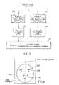
- FIG. 1is a schematic diagram of an image processing system useful in practicing the present invention.
- FIG. 2is a flowchart illustrating the eye detection method of the present invention.
- FIG. 3is an illustration of the relationship between certain geometric parameters and an oval shaped skin color region in an image.
- FIG. 4is an illustration showing, the conditional probability that a given pixel is an iris pixel stated as a function of a specific red intensity and the conditional probability that a given pixel is a non-iris pixel as a function of a specific red intensity.
- FIG. 5is a flowchart presenting the process of developing a statistical model representing the conditional probability that a given pixel is an iris pixel as a function of a specific red intensity level and a statistical model representing the conditional probability that a given pixel is a non-iris pixel as a function of a specific red intensity level.
- FIG. 6is an illustration showing the iris color pixel clusters.
- FIG. 7is a flowchart illustrating the process of applying the method of summation of the squared difference to eye position detection using iris pixel clusters.
- FIG. 8shows an eye template and a search window centered at the center of an iris pixel cluster.
- FIG. 9shows an eye template and an image as used in the process of applying the method of summation of the squared difference to eye position detection using image pixels.
- FIG. 10is a flowchart illustrating the process of training facial feature models and searching facial features.
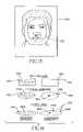
- FIG. 11 ashows examples of manually marked feature points.
- FIG. 11 bshows examples of texture windows at the feature points.
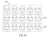
- FIG. 12shows sample facial models.
- FIG. 13shows an initial position of a mean shape in an image.
- FIG. 14illustrates using different schemes to constrain shape model coefficients.
- FIG. 1shows an image processing system useful in practicing the present invention.
- the systemincludes a color digital image source 10 , such as a film scanner, a digital camera, or digital image storage device(such as a compact disk drive with a Picture CD).
- the digital image from the digital image source 10is provided to an image processor 12 , such as a programmed personal computer or a digital image processing work station, such as a Sun Sparc 20 workstation.
- the image processor 12may be connected to a CRT display 14 and an operator interface, such as a keyboard 16 and a mouse 18 .
- the image processor 12is also connected to a computer readable storage medium 17 .
- the image processor 12transmits processed digital images to an output device 19 .
- the output device 19can comprise a hard copy printer, a long term image storage device, a connection to another processor, or an image telecommunication device connected, for example, to the internet.
- the present inventioncomprises a computer program product for detecting facial features in a digital image in accordance with the method described.
- the computer program of the present inventioncan be utilized by any well-known computer system, such as the personal computer of the type shown in FIG. 1 .
- many other types of computer systemscan be used to execute the computer program of the present invention. Consequently, the computer system will not be discussed in further detail herein.
- the computer program product of the present inventionmay make use of image manipulation algorithms and processes that are well known. Accordingly, the present description will be directed in particular to those algorithms and processes forming part of, or cooperating more directly with, the method of the present invention. Thus, it will be understood that the computer program product embodiment of the present invention may embody algorithms and processes not specifically shown or described herein that are useful for implementation. Such algorithms and processes are conventional and within the ordinary skill in such arts.
- the computer program for performing the method of the present inventionmay be stored in a computer readable storage medium.
- This mediummay comprise, for example, magnetic storage media such as a magnetic disk (such as a hard drive or a floppy disk) or magnetic tape; optical storage media such as an optical disc, optical tape, or machine readable bar code; solid state electronic storage devices such as random access memory (RAM), or read only memory (ROM), or any other physical device or medium employed to store a computer program.
- the computer program for performing the method of the present inventionmay also be stored on computer readable storage medium that is connected to the image processor by way of the internet or other communication medium. Those skilled in the art will readily recognize that the equivalent of such a computer program product may also be constructed in hardware.
- FIG. 2is a flow chart illustrating one embodiment of the eye detection method of the present invention.
- FIG. 2shows that a digital color image to be processed is first input into an iris color pixel detection step 200 .
- iris color pixel detectionis accomplished by first detecting skin color regions in the image and then identifying iris color pixels by measuring red intensity levels from within the skin color regions.
- the first step in skin color detectionis color histogram equalization shown in FIG. 2 as step 201 .
- Color histogram equalization step 201receives images to be processed and ensures that the images are in a form that will permit skin color detection. This step is made necessary because human skin may take on any number of colors in an image because of lighting conditions, flash settings and film characteristics. This makes it difficult to automatically detect skin in such images.
- Color Histogram Equalization step 201a statistical analysis of each image is performed. If the statistical analysis suggests that the image may contain regions of skin that have had their appearance modified by lighting conditions, then such images are modified so that skin colored regions can be detected.
- the imageis searched for skin color regions in Skin Color Detection step 202 .
- a preferred method for detecting skin in a digital imageis to separate skin color pixels from other pixels in an image by defining a working color space that contains a range of possible skin colors collected from a large, well-balanced population of images. A pixel is then identified as skin color pixel if the pixel has a color that is within the working color space.
- Skin Color Detection step 202identifies a region of skin color pixels in the image. This region can be defined in any number of ways. In one embodiment, the skin color region is defined by a set of pixel locations identifying the pixels in the image having skin colors. In another embodiment, a modified image is generated that contains only skin color pixels. In yet another embodiment, Skin Color Detection step 202 defines boundaries that confine the skin color region in the image. It will be recognized that more than one skin color region can be identified in the image.
- Oval Region Extraction step 204examines the skin color regions detected by the Skin Color Detection step 202 to locate skin color regions that may be indicative of a face. Because the human face has a roughly oval shape, the skin color regions are examined to locate an oval shaped skin color region. When an oval shaped skin color region is found, the Oval Region Extraction step 204 measures the geometric properties of the oval shaped skin color region. The Oval Region Extraction step 204 uses these measurements to define parameters that describe the size of the face and the location of the face within the image.
- FIG. 3is an illustration of the relationship between the geometric parameters used to define an oval shaped skin color region in the image. As is shown in FIG. 3 , these parameters include Oval_top 300 , Oval_bottom 302 , Oval_left 304 , Oval_right 306 , Oval_center_row 308 , and Oval_center_column 310 . These parameters are used in later steps of the present method to increase the efficiency of the eye detection process. It will be recognized that the method of the present invention can be practiced using skin color detection regions that have shapes that are other than oval and that other geometric parameters can be defined in association with such shapes. It will also be recognized that it is not necessary to detect an oval or other shaped area in the image. In such a case, the skin color region is examined to detect iris color pixels. Further in this case, still other parameters describing the skin color region are defined for use in the eye detection process.
- the oval shaped skin color regionis searched for iris color pixels. This step is performed by Iris Color Pixel Detection step 206 . It will be recognized that limiting the search for iris color pixels to those pixels within the oval shaped skin color region increases the efficiency of the iris color pixel detection. It will also be recognized that there are many ways for iris pixel detection step 200 to detect pixels that are associated with an iris. Such pixels can be identified by simple color thresholding methods, model mapping and other methods well known in the art.
- iris pixelsare detected using the method claimed and described in co-pending and commonly assigned U.S. patent application Ser. No. 09/740,422 filed on 19 Dec. 2000 and entitled “Digital Image Processing Method and Computer Program Product for Detecting Human Irises in an Image”.
- Iris Color Pixel Detection step 206determines whether a pixel is an iris by measuring the red intensity of the pixel. This is done because it has been observed that a human iris has a low red intensity as compared to human skin which has a relatively high red intensity.
- iris color pixelsare not separated from skin color pixels on the basis of a simple threshold method.
- the red intensities of the pixels in the oval shaped skin colored regionare used to determine the probability that each pixel is an iris and to determine the probability that each pixel is not an iris.
- the relationship between the probability that the pixel is an iris and the probability that the pixel is not an irisis then analyzed to determine whether the pixel is an iris pixel.
- the probability that a pixel having a given red intensity is an iris pixelis determined based upon an iris statistical model.
- a non-iris statistical modelis used to define the probability that a given pixel is not an iris pixel based upon the red intensity level of the pixel.
- the relationship between these modelsis non-linear as is shown by way of example in FIG. 4 , which is an illustration showing an example of a statistical model representing the conditional probability 402 that a given pixel is an iris pixel as a function of a specific red intensity I and an example of a statistical model representing the conditional probability 404 that a given pixel is a non-iris pixel as a function of a specific red intensity I.
- the probability analysiscan take many forms.
- the probabilitiescan be combined in various ways with a pixel being classified as an iris or not on the basis of the relationship between these probabilities.
- a mathematical construct known as a Bayes modelis used to combine the probabilities to produce the conditional probability that a pixel having a given red intensity belongs to an iris.
- the Bayes modelis applied as follows:
- I)is the conditional probability that a given pixel intensity belongs to an iris
- iris)is the conditional probability that a given iris pixel has a specific intesity I
- P(iris)is the probability of the occurrence of an iris in the face oval region
- noniris)is the conditional probability that a given non-iris pixel has a specific intesity I
- P(noniris)is the probability of the occurrence of a non-iris pixel in the face oval region.
- the Bayes modelfurther applies the probability of the occurrence of an iris in a face oval region and the probability of the occurrence of a non-iris pixel in the face oval region.
- a probability analysisbased on the Bayes model, a pixel is classified as an iris if the conditional probability that a pixel having a given red intensity belongs to an iris is greater than, for example, 0.05.
- FIG. 5shows a flow chart illustrating the Iris Color Bayes Model Training step 226 used to define the statistical model used to determine whether the pixel is an iris pixel and the statistical model used to determine whether the pixel is a non-iris pixel.
- the method of step 226is performed before the method for detecting irises of the present invention is used to detect irises.
- a large sample of frontal face imagesis collected and examined. All iris pixels and non-iris pixels in the face region are then manually identified 502 and 504 .
- iris)is computed and the probability of the occurrence of an iris in the face oval region, P(iris) 506 is computed, then the conditional probability that a given non-iris pixel has a specific red intensity I, P(I
- the computed statistical models of iris and non-irisare used in the Bayes model to produce the conditional probability that a given pixel intensity belongs to an iris P(iris
- the Bayes modelcan be used to generate a look-up table to be used in Iris Color Pixel Detection step 206 .
- the iris color pixelsare then assigned to clusters. This is done by Iris Pixel Clustering step 208 .
- a clusteris a non-empty set of iris color pixels with the property that any pixel within the cluster is also within a predefined distance to another pixel in the cluster.
- One example of a predefined distanceis one thirtieth of the digital image height.
- the Iris Pixel Clustering step 208 of FIG. 2groups iris color pixels into clusters based upon this definition of a cluster. However, it will be understood that pixels may be clustered on the basis of other criteria.
- the definition of a cluster of iris color pixelsmay be broad enough to include clusters that are invalid.
- the step of validating the clustersis included as step 209 .
- a clustermay be invalid because, for example, it contains too many iris color pixels or because the geometric relationship of the pixels in the cluster suggests that the cluster is not indicative of an iris. For example, if the ratio of a cluster's height to its width is determined, and if the ratio is greater than two, then this cluster is invalid. Invalid iris pixel clusters are removed from further consideration. Accordingly, in the portions of the description that follow, valid iris pixel clusters will be referred to simply as iris pixel clusters.
- the number of iris pixel clusters “n”is counted in step 210 .
- the number of iris pixel clusters “n”is used by decision step 210 to select from among two paths for detecting eyes in an image. If the number of iris pixels “n” is less than two then the process is branched to step 224 which is to be described later. If the number of iris color pixels “n” is at least two, then the process branches to step 212 to find the centers of the clusters.
- the center of a clusteris determined as the center of mass of the cluster.
- the center position of the clustersis calculated with respect to the origin of the image coordinate system. For the purposes of this measurement, the origin of the image coordinate system is at the upper left corner of the image boundary.
- geometric reasoningis applied to attempt to detect eyes based on the geometric relationship between the iris pixel clusters. As is shown in FIG. 6 , if there are only two clusters remaining, with one in the left-half 604 and one in the right-half 606 and if the horizontal distance between the centers of the two clusters is less than 0.4 times the distance between Oval_right 306 and Oval_left 304 and if the vertical distance between the centers of the two clusters is less than one tenth of the distance between Oval_top 300 and Oval_bottom 302 , then the center positions of these two clusters are treated as the eye positions.
- step 216a detection result check is done in step 216 to see if eye positions are detected. If eye positions are detected, then the eye detection process stops. If no eye positions are detected, then the process goes to step 218 .
- the summation of squared difference methodis used to search the image for eye positions.
- the summation of the squared difference methodinvolves calculating the summation of the squared difference of the intensity values of the corresponding pixels in an eye template and a patch of the image that has the same size as the template.
- each pixel in the patch of pixelshas a corresponding pixel in the template.
- the difference between the intensity level of each of the corresponding pixelsis calculated.
- Each differenceis then squared.
- the sum of each of the squared differences for each of the pixels in the setis then calculated. This summation of the squared differences provides a relative measure of the degree of correspondence between each of the pixel sets measured and the template. If no eye positions are detected 220 , then the process goes to 224 .
- summation of the squared difference valuesare calculated for each pixel in each window in each half-region. These values are compared and the cluster having the lowest relative summation of the squared difference value is selected identified as an eye location for the respective half region. This process is performed separately on the clusters of the left and the right-half regions of the image in the manner described below.
- the parameters calculated in the Oval Region Detection Step 204are used to increase the efficiency of the use of the summation of the squared difference method by reducing the number of locations in the image at which the summation of the squared difference must be calculated.
- the Oval_Center_Column 310is used to divide the oval region into a left-half region 604 and a right-half region 606 .
- iris pixel clusters 600 and the center position 602 of the iris pixel clusters 600are positioned in either the left-half or right-half regions 604 and 606 separated by the Oval_Center_Column 310 .
- Step 218conducts a left-eye position search using the summation of squared difference method and the pixel clusters 600 located on the left-half region 604 .
- Step 218also conducts a right-eye position search in the right-half region using the summation of squared difference method and the iris pixel clusters 600 located in the right-half region 606 .
- the eye position search processis started by centering 70 a window 800 at the center of each cluster 802 in a respective half-region.
- the default size for window 800is one twentieth of the size of the image 804 .
- the operation of calculating the summation of the squared differences 72is then performed on each of the pixels in each window 800 .
- the position of the pixel having the lowest summation of squared difference value in each window 800is recorded 76 .
- the position of the pixel having the lowest summation of squared difference valueis recorded 79 . This is the estimated eye position for a half-region. This process is repeated for the remaining half-region. If two eyes are detected by this process, then the method is ended.
- the summation of the squared difference method of step 218can also be performed without the use of Oval Shaped Skin Color Extraction.
- the skin color regioncan be divided into a left-half region and a right-half region.
- Iris pixel clusterscan then be divided into left-half region and right-half region clusters.
- the summation of the squared difference methodcan then be applied as described above.
- Step 224operates in a manner that is similar to step 218 .
- the entire image 900is divided and a summation of the squared difference is calculated for every pixel of the image 904 in the left-half 908 and right-half 910 region respectively.
- the present inventionprovides three distinct steps methods to detect eyes in an image; geometric reasoning 212 and 214 , summation of the squared difference using iris pixel clusters 218 and summation of the squared difference using image pixels 224 .
- geometric reasoningis the simplest and most efficient of these methods. This is because geometric reasoning provides the most efficient processing method and because geometric reasoning is applied only to iris pixel clusters. These clusters are relatively small in number when compared to the number of pixels in the image.
- step 224applying a summation of the squared difference method to each of the pixels in an image as is required in step 224 is a computationally heavy step, requiring many processing steps and calculations to determine whether a single pixel in the image is an eye position. Further, the method of step 224 must be applied to all of the non-iris pixels in an image. In a currently common format, digital images are being acquired by 2.1 megapixel cameras. Further, cameras having as many as 16 megapixels have been demonstrated. Thus, it is clear that using step 224 to detect eye positions in an image will require, literally, hundreds of millions of operations to process a single image. This is a time and computer intensive process.
- step 218applies a computationally heavy summation of the squared difference method, but limits the application of this method to the pixels in the windows defined about the iris pixel clusters. This substantially reduces the number of pixels to which the summation of the squared difference method must be applied and therefore makes the application of the summation of the squared difference method 220 less computer intensive than the summation of the squared difference method of step 224 .
- Step 1000 locating facial features in FIG. 2is now detailed in FIG. 10 .
- a “Posed” image databasewas initially selected as the ground truth images 1010 .
- This databasecomprises portrait style pictures that depict a frontal view of the subjects.
- the faces in the databaseare similarly sized with an exemplary average inter-ocular distance of 83 pixels.
- the active shape model techniquerepresents object shapes with one or more groups of connected feature points. These feature points determine the locations where local searches are performed. The connections between points determine the boundary normals that are used to define the search directions and the texture window orientations. The feature points indicate a series of application specific “landmark” positions, and are typically placed along the border of an object. The connections between points normally designate the edges of the object. There are a number of engineering decisions that must be made when modeling the shape of the object. The most important of these decisions is determining where to place the feature points. These points should be positioned on consistent and unique textures that are easily identifiable from the surrounding area. Edges and corners of an object are usually good landmark points. If multiple points are placed along a given edge they should be distributed at fixed intervals to avoid introducing unnecessary variability into the shape model.
- the quantity of the feature pointsis another important decision. Increasing the number of points can improve the accuracy of the results and provide a better description of the object shape.
- the relative density of the feature pointsis also significant. Each point has an equivalent influence on the resulting shape of the object. Therefore, areas with a high density of feature points tend to have a greater accuracy than regions with a sparse distribution of points.
- the normalsdetermine the predominant search directions and influence the likelihood that the correct points will be found.
- the normalsalso control the alignment of the primary axis of the texture windows. This affects the ability of the model to capture the salient textural attributes.
- FIG. 11 aillustrates the facial feature model and depicts the annotated feature positions 1120 in an example image 1110 .
- the correct placement of the feature pointsis often ambiguous. This can occur when objects such as hair or glasses occlude the desired features. A decision must be made to either select consistent locations or consistent textural features (edges). The appropriate choice depends upon the application.
- a texture modelis created by first defining a rectangular texture window 1140 to be centered over the associated feature point as illustrated in FIG. 11 b .
- This windowspecifies the region of the image to be described by the model.
- the usercan specify the extent and resolution of the window. An example resolution of 1 by 15 pixels was use in this invention.
- the major axis of the windowis aligned with the normal to the shape boundary.
- the texture windowis automatically scaled based on the size of the shape.
- the scale factoris determined from the optimal Euclidean transformation that aligns the example with the mean shape. This ensures that the windows for each image cover a consistent portion of the object.
- a training algorithmis used to analyze the ground truth data. This algorithm learns models that are employed during subsequent searches. The training process does not require user interaction. Models of both shape and texture are created. The shape model describes the expected relative positions of the feature points. The texture models represent the anticipated appearances of each feature point. These models only need to be generated once and are stored for later use.
- the shape modeldescribes the “space” of allowable feature positions. This model is used to constrain unlikely search results to the domain of plausible shapes.
- the shape modelconsists of the mean shape, the primary modes of shape variation, and the associated ranges for each of the modes.
- the initial step in learning the shape model 1012is to align the feature positions from the ground truth into a common coordinate system. This eliminates variation from the model that is the result of global transformation.
- PCAprovides a method to reduce the dimensionality of the shape space while retaining its salient features. This is accomplished by computing a set of orthogonal axes that are aligned with the directions of the most significant variation in the point cloud of example shapes. These axes indicate the most common modes of variation in the shape. The axes form an optimal basis that can be used to represent valid shapes with a minimum number of parameters.
- the aligned feature coordinates of each example shapecan be arranged into a vector x i of length 2N.
- the covariance matrix Sis produced from the expression:
- FIG. 12illustrates three most significant axes of the facial shape model. Portrayed shapes are the results of varying the mean shape along the given eigenvector. It is interesting to note that a number of the primary axes are strongly related to semantically meaningful variations in the face shape. For instance, the first axis 1210 is related to the position of the hairline, the second axis 1212 is associated with the forward tilt of the head, and the third axis 1214 is correlated with the facial width.
- the majority of the shape spacecan often be represented with relatively few of the primary axes.
- the number of axes to retaincan be determined from the eigenvalues.
- the eigenvaluesare equal to the variance of the ground truth along the axis specified by the corresponding eigenvector.
- the appropriate number of axescan be determined by selecting the quantity that encapsulate a given fraction f of the total variance (e.g. 0.98). This is accomplished by selecting the first M eigenvectors such that
- Any shapecan be made to resemble the examples in the ground truth by determining the vector of weights and placing limits on the range of these values. Suitable limits can be derived from the eigenvalues that specify the variance of the ground truth along each axis.
- One possibilityis to limit the weights to a range of 3 standard deviations along each axis. This can be accomplished by clipping the weights so that ⁇ 3 ⁇ square root over ( ⁇ k ) ⁇ b k ⁇ 3 ⁇ square root over ( ⁇ k ) ⁇ .
- step 1014the region of the image covered by the texture window is extracted for every resolution at each feature point and encoded for each example in the ground truth and then texture models are calculated using the encoded textures.
- the textureis originally represented as a color RGB image in sRGB color space.
- the intensity gradient profileis calculated for each color channel. This is accomplished by computing the difference of neighboring pixel values along the normal direction.
- the gradient profilesare then normalized by the mean intensity and combined into a single vector t. This representation retains information about the orientation and relative positions of color edges within the texture window and normalizes out the absolute intensity and edge strength. This has the benefit of adequately describing the appearance of the texture while minimizing the effect of brightness and contrast changes within the image.
- the encoded textures from each exampleare used to calculate the final texture model.
- This modelconsists of the mean encoded texture t and the covariance matrix S t .
- This matrixis calculated as in Equation 1 , albeit with slightly different variable names.
- the covariance matrixserves to describe the range of variation of each pixel in the texture as well as how the individual pixels co-vary. This provides a complete statistical representation of the distribution of example textures if we assume a unimodal Gaussian distribution.
- the texture modelprovides the basis for determining the goodness of fit of texture candidates.
- a separate texture modelneeds to be created for every resolution at each feature point.
- the models for various levelsare all centered over the feature point and encoded using the same number of pixels.
- a coarse texturetypically covers twice the extent of each successively finer texture.
- FIG. 13displays an exemplary image 1300 for facial feature finding.
- a mean shape 1310 obtained from step 1012is initialized in step 1015 at the eye positions obtained from one of the three steps: step 216 , step 220 , or step 224 .
- the positions of the feature points 1120 within an imageare determined by performing a series of local searches in step 1016 .
- the current estimates of the feature locations of the mean shape model 1310 at the initial position determined by the estimated eye locationsare used to initialize the search positions.
- a number of texture windows 1140are extracted from the area surrounding each point on the shape model 1310 . The contents of these windows are compared with the texture model developed in step 1014 to determine the position that best matches the expected appearance of the feature.
- the search directionis oriented along the normal to the shape boundary.
- the usercan specify the spacing and quantity of the search positions.
- an exemplary range of 3 by 7 set of locationsis investigated.
- the search intervalsare dynamically scaled to insure that a consistent region of the face is covered.
- a texture window 1140is extracted and encoded as discussed in step 1014 .
- the similarity of the texture window to the texture modelis measured by the Mahalanobis distance described in Equation 7 .
- the position with the minimum distanceis selected as the new feature location. This process is repeated for each feature point.
- the feature positions 1120 identified by the local texture matching stepare prone to error. This error is due in part to the variable appearance of the features and to their similarity with surrounding regions. The accuracy is also limited by the small size of the texture windows 1140 that are necessary to localize the precise positions of the features. The quality of the search results can be significantly improved by limiting the feature points to the range of plausible shapes that is described by the shape model.
- the feature points 1120can be constrained to valid shapes by using the following process.
- the Euclidean transform that aligns the two shapesis determined from a least squares fit.
- the aligned feature coordinatesare projected into the PCA shape space using Equation 5 .
- the shape coefficientsare then limited to a reasonable range. A range that includes an exemplary 99.975% of valid shapes was used in this invention.
- the feature locations 1120 that correspond to the limited shape coefficientsare computed using Equation 4.
- the Euclidean transformationis inverted to convert the aligned shape back into image coordinates.
- FIG. 14There are a number of ways to constrain the shape coefficients. Three approaches are illustrated in FIG. 14 . The simplest method is to merely clip each coefficient so that it does not exceed a given number of standard deviations of the ground truth 1410 along each axis. These limits are described in Equation 6. This corresponds to using a multi-dimensional box 1450 for the limits as illustrated in FIG. 14 . An estimated shape 1416 outside the ground truth space 1410 could be constrained to a shape 1426 at the box corner. The problem with this approach is that the shapes 1426 that reside at the corners of the box have a significantly lower likelihood of occurrence than the specified threshold.
- a better approachis to use a hyper-elliptical boundary 1452 to limit the range of the coefficients. This can be accomplished by uniformly scaling all coefficients so that
- the constrained shapewill be the intersection point 1436 of the ellipse boundary 1452 and the line between the estimated shape point 1416 and the ellipse center 1460 .
- the point 1460is not necessary the closest point on the ellipse boundary to the point 1416 .
- a better shapecan be found by choosing the point 1446 on the boundary of the hyper-ellipse that is nearest the position of starting shape 1416 .
- This approachis depicted in the bottom diagram of FIG. 14 .
- the point 1448 that would be erroneously selected by the elliptical constraint methodis given by the intersection of the dotted line with the elliptical boundary.
- Hartdescribes the algorithm for the case of a 3-dimensional ellipse. This approach is relatively straightforward to extend to an arbitrary number of dimensions.
- step 1020the process of finding local texture matches and then constraining the global shape is repeated until the shape converges upon a stable result. It is possible to measure the amount that the shape changes on each iteration and discontinue the process when the change drops below a given threshold. However, the shape converges so rapidly that this is not necessary. Instead, good results have been achieved by merely repeating the process for a fixed number of iterations.
- the active shape model algorithmcan be implemented in a multi-resolution framework with step 1022 . This efficiently extends the range over which features can be accurately identified.
- the multi-resolution version of the algorithminitially searches the image using large, coarse texture models and wide search areas. The approximate feature positions are then refined using successively smaller and finer texture models and narrower search areas.
- the positions that are examined when searchingare scaled similarly to the texture windows. These locations are centered over the current estimate of the feature position and the same number of points is investigated at each resolution.
- the spacing between the search locations that are used with a coarse texture modelis generally double that used with each consecutively finer texture model.
- the searching algorithminitially uses the coarsest texture models and the most widely spaced search locations.
- the process of local texture matching and constraining the global shapeis repeated until the shape is converged. This process is repeated for each resolution using finer texture models and more narrowly spaced search intervals. Four resolutions were used in this work to provide both a large search interval and fine localization of the feature positions.
- the method of the present inventionprovides a way for automatically selecting between these eye detection methods and combining these methods in a manner that uses the number of iris pixel clusters to select the most efficient method for detecting eyes in the image.
- the subject matter of the present inventionrelates to digital image understanding technology, which is understood to mean technology that digitally processes a digital image to recognize and thereby assign useful meaning to human understandable objects, attributes or conditions and then to utilize the results obtained in the further processing of the digital image.
Landscapes
- Engineering & Computer Science (AREA)
- Physics & Mathematics (AREA)
- Theoretical Computer Science (AREA)
- Health & Medical Sciences (AREA)
- General Physics & Mathematics (AREA)
- Oral & Maxillofacial Surgery (AREA)
- General Health & Medical Sciences (AREA)
- Computer Vision & Pattern Recognition (AREA)
- Multimedia (AREA)
- Human Computer Interaction (AREA)
- Ophthalmology & Optometry (AREA)
- Image Analysis (AREA)
- Image Processing (AREA)
- Measurement Of The Respiration, Hearing Ability, Form, And Blood Characteristics Of Living Organisms (AREA)
- Collating Specific Patterns (AREA)
Abstract
Description
where P(iris|I) is the conditional probability that a given pixel intensity belongs to an iris; P(I|iris) is the conditional probability that a given iris pixel has a specific intesity I; P(iris) is the probability of the occurrence of an iris in the face oval region; P(I|noniris) is the conditional probability that a given non-iris pixel has a specific intesity I; and P(noniris) is the probability of the occurrence of a non-iris pixel in the face oval region. The Bayes model further applies the probability of the occurrence of an iris in a face oval region and the probability of the occurrence of a non-iris pixel in the face oval region. Using a probability analysis based on the Bayes model, a pixel is classified as an iris if the conditional probability that a pixel having a given red intensity belongs to an iris is greater than, for example, 0.05.
- 1. Select one example as an initial estimate of the mean shape.
- 2. Normalize the scale and orientation of the mean
- 3. Align all shapes with the current estimate of the mean. The optimal Euclidean transformation (translation, scale, and rotation) is determined by a least squares fit.
- 4. Re-estimate the mean from the aligned shapes.
- 5. Repeat steps 2-4 until the estimate of the mean converges. Shapes can be thought of as points in a 2P-dimensional space, where P is the number of 2-dimensional feature points. The aligned ground truth forms a cloud of points in this space with limits that can be modeled by a hyper-elliptical boundary. A compact representation of this boundary can be derived from a principal components analysis (PCA).
where N is the number of ground truth examples. An ordered list of the principal axes is given by the unit eigenvectors vk(k=1, . . . , 2N) such that
Svk=λkvk, (2)
where λkis the ktheigenvalue and λk≧λk+1. The eigenvectors that correspond to the largest eigenvalues indicate the most common modes of variation in the shape.
An arbitrary shape can be approximated from the mean shape and a linear combination of perturbations along these axes using
x=
where V=(V1V2. . . VM) is the matrix of the first M eigenvectors, and b=(b1b2. . . bM)Tis a vector of weights. The vector of weights forms the parameters of the shape model and can be computed from a given set of feature positions from the inverse expression
b=VT(x−
Any shape can be made to resemble the examples in the ground truth by determining the vector of weights and placing limits on the range of these values. Suitable limits can be derived from the eigenvalues that specify the variance of the ground truth along each axis. One possibility is to limit the weights to a range of 3 standard deviations along each axis. This can be accomplished by clipping the weights so that
−3√{square root over (λk)}≦bk≦3√{square root over (λk)}. (6)
f(t)=(t−
where f(t) specifies the weighted distance of the candidate from the mean. This value is linearly related to the log of the probability that the candidate comes from the example distribution.
where the limit l is chosen using the χ2distribution. This approach is illustrated in the middle diagram of
- 10 digital image source
- 12 image processor
- 14 display
- 16 keyboard
- 17 computer readable storage medium
- 18 mouse
- 19 output device
- 70 centering window step
- 72 summation of squared difference calculator
- 74 checking step
- 76 position recording step
- 78 checking step
- 79 position recording step
- 200 pixel detection
- 201 color histogram equalization step
- 202 skin detection step
- 204 oval region extraction step
- 206 iris color pixel detection step
- 208 iris pixel clustering step
- 209 pixel validation step
- 210 number of pixels detected decision step
- 212 finding centers of iris color pixel clusters
- 214 detecting eye positions based on geometric reasoning
- 216 eyes detected decision step
- 218 detecting eye positions based on summation of squared difference using iris pixel clusters
- 220 eyes detected decision step
- 224 detecting eye positions using a summation of squared difference method using image pixels
- 226 iris color Bayesian model training
- 300 Oval_top
- 302 Oval_bottom
- 304 Oval_left
- 306 Oval right
- 308 Oval_center_row
- 310 Oval_center_column
- 402 statistical model of probability that a pixel is an iris
- 404 statistical model of probability that a pixel is not an iris
- 502 manually identifying iris pixels for statistical model
- 504 manually identifying non-iris pixels for statistical model
- 506 computing probability step
- 508 computing probability step
- 510 applying Bayes model
- 600 cluster center
- 602 iris color pixel
- 604 left half region
- 606 right half region
- 800 a window
- 802 average eye template moving in window
- 804 image
- 806 average eye template
- 902 an average eye template moving in the image
- 904 image
- 906 average eye template
- 908 a left-half of image
- 910 a right-half
- 1000 locating facial feature step
- 1010 collecting ground truth step
- 1012 learning shape model step
- 1014 learning multi-resolution texture model step
- 1015 initialization step
- 1016 local texture matching step
- 1018 constraining shape step
- 1020 converge checking step
- 1022 resolution checking step
- 1110 an image
- 1120 feature points
- 1140 texture windows
- 1210 sample shapes
- 1212 sample shapes
- 1214 sample shapes
- 1300 an image
- 1310 a mean shape
- 1410 ground truth
- 1416 a sample shape
- 1426 a shape point
- 1436 a shape point
- 1446 a shape point
- 1448 a shape point
- 1450 a boundary
- 1452 a boundary
- 1454 a boundary
- 1460 a mean shape point
- 1462 a mean shape point
Claims (37)
Priority Applications (1)
| Application Number | Priority Date | Filing Date | Title |
|---|---|---|---|
| US11/042,503US7254256B2 (en) | 2001-09-20 | 2005-01-25 | Method and computer program product for locating facial features |
Applications Claiming Priority (3)
| Application Number | Priority Date | Filing Date | Title |
|---|---|---|---|
| US32357901P | 2001-09-20 | 2001-09-20 | |
| US09/994,096US7058209B2 (en) | 2001-09-20 | 2001-11-26 | Method and computer program product for locating facial features |
| US11/042,503US7254256B2 (en) | 2001-09-20 | 2005-01-25 | Method and computer program product for locating facial features |
Related Parent Applications (1)
| Application Number | Title | Priority Date | Filing Date |
|---|---|---|---|
| US09/994,096ContinuationUS7058209B2 (en) | 2001-09-20 | 2001-11-26 | Method and computer program product for locating facial features |
Publications (2)
| Publication Number | Publication Date |
|---|---|
| US20050129288A1 US20050129288A1 (en) | 2005-06-16 |
| US7254256B2true US7254256B2 (en) | 2007-08-07 |
Family
ID=26984034
Family Applications (2)
| Application Number | Title | Priority Date | Filing Date |
|---|---|---|---|
| US09/994,096Expired - LifetimeUS7058209B2 (en) | 2001-09-20 | 2001-11-26 | Method and computer program product for locating facial features |
| US11/042,503Expired - LifetimeUS7254256B2 (en) | 2001-09-20 | 2005-01-25 | Method and computer program product for locating facial features |
Family Applications Before (1)
| Application Number | Title | Priority Date | Filing Date |
|---|---|---|---|
| US09/994,096Expired - LifetimeUS7058209B2 (en) | 2001-09-20 | 2001-11-26 | Method and computer program product for locating facial features |
Country Status (4)
| Country | Link |
|---|---|
| US (2) | US7058209B2 (en) |
| EP (1) | EP1296279B1 (en) |
| JP (1) | JP4234381B2 (en) |
| DE (1) | DE60215743T2 (en) |
Cited By (5)
| Publication number | Priority date | Publication date | Assignee | Title |
|---|---|---|---|---|
| US20060098867A1 (en)* | 2004-11-10 | 2006-05-11 | Eastman Kodak Company | Detecting irises and pupils in images of humans |
| US20090243798A1 (en)* | 2008-03-25 | 2009-10-01 | Fujitsu Limited | Biometric authentication apparatus and biometric data registration apparatus |
| US9158963B2 (en) | 2012-10-04 | 2015-10-13 | Adobe Systems Incorporated | Fitting contours to features |
| US9202138B2 (en) | 2012-10-04 | 2015-12-01 | Adobe Systems Incorporated | Adjusting a contour by a shape model |
| US10089327B2 (en) | 2011-08-18 | 2018-10-02 | Qualcomm Incorporated | Smart camera for sharing pictures automatically |
Families Citing this family (149)
| Publication number | Priority date | Publication date | Assignee | Title |
|---|---|---|---|---|
| US8480754B2 (en) | 2001-05-25 | 2013-07-09 | Conformis, Inc. | Patient-adapted and improved articular implants, designs and related guide tools |
| US8735773B2 (en) | 2007-02-14 | 2014-05-27 | Conformis, Inc. | Implant device and method for manufacture |
| US9603711B2 (en) | 2001-05-25 | 2017-03-28 | Conformis, Inc. | Patient-adapted and improved articular implants, designs and related guide tools |
| US8882847B2 (en) | 2001-05-25 | 2014-11-11 | Conformis, Inc. | Patient selectable knee joint arthroplasty devices |
| US8617242B2 (en) | 2001-05-25 | 2013-12-31 | Conformis, Inc. | Implant device and method for manufacture |
| US8771365B2 (en) | 2009-02-25 | 2014-07-08 | Conformis, Inc. | Patient-adapted and improved orthopedic implants, designs, and related tools |
| US8545569B2 (en) | 2001-05-25 | 2013-10-01 | Conformis, Inc. | Patient selectable knee arthroplasty devices |
| US20030055502A1 (en) | 2001-05-25 | 2003-03-20 | Philipp Lang | Methods and compositions for articular resurfacing |
| US8556983B2 (en) | 2001-05-25 | 2013-10-15 | Conformis, Inc. | Patient-adapted and improved orthopedic implants, designs and related tools |
| WO2000035346A2 (en) | 1998-09-14 | 2000-06-22 | Stanford University | Assessing the condition of a joint and preventing damage |
| US7239908B1 (en) | 1998-09-14 | 2007-07-03 | The Board Of Trustees Of The Leland Stanford Junior University | Assessing the condition of a joint and devising treatment |
| DE60136474D1 (en) | 2000-09-14 | 2008-12-18 | Univ R | ASSESSMENT OF THE CONDITION OF A JOINT AND LOSS OF CARTEL TISSUE |
| ATE426357T1 (en) | 2000-09-14 | 2009-04-15 | Univ Leland Stanford Junior | ASSESSING THE CONDITION OF A JOINT AND PLANNING TREATMENT |
| AUPS140502A0 (en)* | 2002-03-27 | 2002-05-09 | Seeing Machines Pty Ltd | Method for automatic detection of facial features |
| JP2006501977A (en) | 2002-10-07 | 2006-01-19 | コンフォーミス・インコーポレイテッド | Minimally invasive joint implant with a three-dimensional profile that conforms to the joint surface |
| JP2006505366A (en) | 2002-11-07 | 2006-02-16 | コンフォーミス・インコーポレイテッド | Method of determining meniscus size and shape and devised treatment |
| US7039222B2 (en)* | 2003-02-28 | 2006-05-02 | Eastman Kodak Company | Method and system for enhancing portrait images that are processed in a batch mode |
| US7324693B2 (en) | 2003-04-23 | 2008-01-29 | Eastman Kodak Company | Method of human figure contour outlining in images |
| US20040223649A1 (en)* | 2003-05-07 | 2004-11-11 | Eastman Kodak Company | Composite imaging method and system |
| US7224850B2 (en)* | 2003-05-13 | 2007-05-29 | Microsoft Corporation | Modification of red-eye-effect in digital image |
| JP4789408B2 (en)* | 2003-06-30 | 2011-10-12 | 株式会社 資生堂 | Eye form classification method, form classification map, and eye makeup method |
| JP4307301B2 (en)* | 2003-07-31 | 2009-08-05 | キヤノン株式会社 | Image processing apparatus and method |
| US7333653B2 (en)* | 2003-08-29 | 2008-02-19 | Hewlett-Packard Development Company, L.P. | Detecting and correcting redeye in an image |
| US7593550B2 (en)* | 2005-01-26 | 2009-09-22 | Honeywell International Inc. | Distance iris recognition |
| US8090157B2 (en)* | 2005-01-26 | 2012-01-03 | Honeywell International Inc. | Approaches and apparatus for eye detection in a digital image |
| US7761453B2 (en)* | 2005-01-26 | 2010-07-20 | Honeywell International Inc. | Method and system for indexing and searching an iris image database |
| US8064647B2 (en) | 2006-03-03 | 2011-11-22 | Honeywell International Inc. | System for iris detection tracking and recognition at a distance |
| US8098901B2 (en)* | 2005-01-26 | 2012-01-17 | Honeywell International Inc. | Standoff iris recognition system |
| US8705808B2 (en) | 2003-09-05 | 2014-04-22 | Honeywell International Inc. | Combined face and iris recognition system |
| US8442276B2 (en)* | 2006-03-03 | 2013-05-14 | Honeywell International Inc. | Invariant radial iris segmentation |
| US7617002B2 (en)* | 2003-09-15 | 2009-11-10 | Medtronic, Inc. | Selection of neurostimulator parameter configurations using decision trees |
| US7239926B2 (en)* | 2003-09-15 | 2007-07-03 | Medtronic, Inc. | Selection of neurostimulator parameter configurations using genetic algorithms |
| US7252090B2 (en)* | 2003-09-15 | 2007-08-07 | Medtronic, Inc. | Selection of neurostimulator parameter configurations using neural network |
| US7184837B2 (en)* | 2003-09-15 | 2007-02-27 | Medtronic, Inc. | Selection of neurostimulator parameter configurations using bayesian networks |
| US7295686B2 (en)* | 2003-09-29 | 2007-11-13 | Primax Electronics Ltd. | Method of processing red eye in digital images |
| TWI220234B (en)* | 2003-10-21 | 2004-08-11 | Ind Tech Res Inst | A method to simulate animated images for an object |
| JP4431949B2 (en)* | 2003-10-27 | 2010-03-17 | ノーリツ鋼機株式会社 | Red-eye correction method and apparatus for carrying out this method |
| KR100601933B1 (en)* | 2003-11-18 | 2006-07-14 | 삼성전자주식회사 | Person detection method and device and privacy protection method and system using same |
| GB2414616A (en)* | 2004-05-28 | 2005-11-30 | Sony Uk Ltd | Comparing test image with a set of reference images |
| JP2005293555A (en)* | 2004-03-10 | 2005-10-20 | Seiko Epson Corp | Identification of skin area in image |
| US7660482B2 (en)* | 2004-06-23 | 2010-02-09 | Seiko Epson Corporation | Method and apparatus for converting a photo to a caricature image |
| US7627148B2 (en)* | 2004-07-06 | 2009-12-01 | Fujifilm Corporation | Image data processing apparatus and method, and image data processing program |
| US7689010B2 (en)* | 2004-12-03 | 2010-03-30 | Invacare International Sarl | Facial feature analysis system |
| US20060148323A1 (en)* | 2004-12-03 | 2006-07-06 | Ulrich Canzler | Facial feature analysis system |
| US7809171B2 (en)* | 2005-01-10 | 2010-10-05 | Battelle Memorial Institute | Facial feature evaluation based on eye location |
| US7548637B2 (en)* | 2005-04-07 | 2009-06-16 | The Board Of Trustees Of The University Of Illinois | Method for detecting objects in an image using pair-wise pixel discriminative features |
| US7747050B2 (en)* | 2005-11-23 | 2010-06-29 | General Electric Company | System and method for linking current and previous images based on anatomy |
| US7627149B2 (en)* | 2005-11-25 | 2009-12-01 | Quantum Signal, Llc | Dot templates for object detection in images |
| US7643659B2 (en)* | 2005-12-31 | 2010-01-05 | Arcsoft, Inc. | Facial feature detection on mobile devices |
| US7646894B2 (en)* | 2006-02-14 | 2010-01-12 | Microsoft Corporation | Bayesian competitive model integrated with a generative classifier for unspecific person verification |
| JP4620607B2 (en)* | 2006-02-24 | 2011-01-26 | 株式会社モルフォ | Image processing device |
| JP2007233871A (en)* | 2006-03-02 | 2007-09-13 | Fuji Xerox Co Ltd | Image processor, control method for computer, and program |
| WO2008019169A2 (en) | 2006-03-03 | 2008-02-14 | Honeywell International, Inc. | Iris encoding system |
| AU2007281940B2 (en) | 2006-03-03 | 2010-12-16 | Gentex Corporation | Modular biometrics collection system architecture |
| WO2007101276A1 (en)* | 2006-03-03 | 2007-09-07 | Honeywell International, Inc. | Single lens splitter camera |
| DE602007007062D1 (en)* | 2006-03-03 | 2010-07-22 | Honeywell Int Inc | IRISER IDENTIFICATION SYSTEM WITH IMAGE QUALITY METERING |
| WO2007101275A1 (en) | 2006-03-03 | 2007-09-07 | Honeywell International, Inc. | Camera with auto-focus capability |
| US7787664B2 (en)* | 2006-03-29 | 2010-08-31 | Eastman Kodak Company | Recomposing photographs from multiple frames |
| US8380300B2 (en)* | 2006-04-28 | 2013-02-19 | Medtronic, Inc. | Efficacy visualization |
| US8306624B2 (en) | 2006-04-28 | 2012-11-06 | Medtronic, Inc. | Patient-individualized efficacy rating |
| US7715920B2 (en)* | 2006-04-28 | 2010-05-11 | Medtronic, Inc. | Tree-based electrical stimulator programming |
| KR100778116B1 (en)* | 2006-10-02 | 2007-11-21 | 삼성전자주식회사 | Motion vector correction device and correction method |
| US8103061B2 (en)* | 2006-10-02 | 2012-01-24 | Johnson & Johnson Consumer Companies, Inc. | Method and apparatus for identifying facial regions |
| US7764303B2 (en) | 2006-10-02 | 2010-07-27 | Johnson & Johnson Consumer Companies, Inc. | Imaging apparatus and methods for capturing and analyzing digital images of the skin |
| JP4175425B2 (en)* | 2007-03-15 | 2008-11-05 | オムロン株式会社 | Pupil color correction apparatus and program |
| JP4307496B2 (en)* | 2007-03-19 | 2009-08-05 | 株式会社豊田中央研究所 | Facial part detection device and program |
| US8063889B2 (en)* | 2007-04-25 | 2011-11-22 | Honeywell International Inc. | Biometric data collection system |
| US8038614B2 (en)* | 2007-05-22 | 2011-10-18 | Eastman Kodak Company | Establishing baseline data for physiological monitoring system |
| US8831299B2 (en) | 2007-05-22 | 2014-09-09 | Intellectual Ventures Fund 83 Llc | Capturing data for individual physiological monitoring |
| US20080294018A1 (en)* | 2007-05-22 | 2008-11-27 | Kurtz Andrew F | Privacy management for well-being monitoring |
| US8038615B2 (en)* | 2007-05-22 | 2011-10-18 | Eastman Kodak Company | Inferring wellness from physiological conditions data |
| US7972266B2 (en)* | 2007-05-22 | 2011-07-05 | Eastman Kodak Company | Image data normalization for a monitoring system |
| US20080294012A1 (en)* | 2007-05-22 | 2008-11-27 | Kurtz Andrew F | Monitoring physiological conditions |
| US8437514B2 (en) | 2007-10-02 | 2013-05-07 | Microsoft Corporation | Cartoon face generation |
| CA2897227C (en) | 2007-12-31 | 2017-01-10 | Applied Recognition Inc. | Method, system, and computer program for identification and sharing of digital images with face signatures |
| US9721148B2 (en) | 2007-12-31 | 2017-08-01 | Applied Recognition Inc. | Face detection and recognition |
| US9639740B2 (en) | 2007-12-31 | 2017-05-02 | Applied Recognition Inc. | Face detection and recognition |
| JP5290585B2 (en)* | 2008-01-17 | 2013-09-18 | 株式会社 資生堂 | Skin color evaluation method, skin color evaluation device, skin color evaluation program, and recording medium on which the program is recorded |
| US8218862B2 (en)* | 2008-02-01 | 2012-07-10 | Canfield Scientific, Incorporated | Automatic mask design and registration and feature detection for computer-aided skin analysis |
| US20090214114A1 (en)* | 2008-02-19 | 2009-08-27 | Diascan Ab | Pixel classification in image analysis |
| AU2009221773B2 (en)* | 2008-03-05 | 2015-03-05 | Conformis, Inc. | Edge-matched articular implant |
| WO2009111626A2 (en) | 2008-03-05 | 2009-09-11 | Conformis, Inc. | Implants for altering wear patterns of articular surfaces |
| JP2009223580A (en)* | 2008-03-14 | 2009-10-01 | Omron Corp | Priority target determination device, electronic apparatus, priority target determination method, program, and recording medium |
| US8165354B1 (en)* | 2008-03-18 | 2012-04-24 | Google Inc. | Face recognition with discriminative face alignment |
| US8027521B1 (en) | 2008-03-25 | 2011-09-27 | Videomining Corporation | Method and system for robust human gender recognition using facial feature localization |
| US8831379B2 (en)* | 2008-04-04 | 2014-09-09 | Microsoft Corporation | Cartoon personalization |
| US8436907B2 (en) | 2008-05-09 | 2013-05-07 | Honeywell International Inc. | Heterogeneous video capturing system |
| WO2009140294A1 (en) | 2008-05-12 | 2009-11-19 | Conformis, Inc. | Devices and methods for treatment of facet and other joints |
| US8213782B2 (en) | 2008-08-07 | 2012-07-03 | Honeywell International Inc. | Predictive autofocusing system |
| US8090246B2 (en)* | 2008-08-08 | 2012-01-03 | Honeywell International Inc. | Image acquisition system |
| US8280119B2 (en) | 2008-12-05 | 2012-10-02 | Honeywell International Inc. | Iris recognition system using quality metrics |
| US7912252B2 (en)* | 2009-02-06 | 2011-03-22 | Robert Bosch Gmbh | Time-of-flight sensor-assisted iris capture system and method |
| WO2010099231A2 (en) | 2009-02-24 | 2010-09-02 | Conformis, Inc. | Automated systems for manufacturing patient-specific orthopedic implants and instrumentation |
| US8121358B2 (en)* | 2009-03-06 | 2012-02-21 | Cyberlink Corp. | Method of grouping images by face |
| US8531478B2 (en)* | 2009-03-19 | 2013-09-10 | Cyberlink Corp. | Method of browsing photos based on people |
| US8630464B2 (en) | 2009-06-15 | 2014-01-14 | Honeywell International Inc. | Adaptive iris matching using database indexing |
| US8472681B2 (en) | 2009-06-15 | 2013-06-25 | Honeywell International Inc. | Iris and ocular recognition system using trace transforms |
| KR101590868B1 (en)* | 2009-07-17 | 2016-02-02 | 삼성전자주식회사 | A image processing method an image processing apparatus a digital photographing apparatus and a computer-readable storage medium for correcting skin color |
| US8929614B2 (en)* | 2009-10-19 | 2015-01-06 | Hewlett-Packard Development Company, L.P. | Red eye detection aided by face detection |
| CA2782137A1 (en) | 2009-12-11 | 2011-06-16 | Conformis, Inc. | Patient-specific and patient-engineered orthopedic implants |
| IT1397571B1 (en) | 2009-12-18 | 2013-01-16 | St Microelectronics Srl | METHOD AND FILTERING APPARATUS OF ARTIFACTS FROM RED AND / OR YELLOW EYES. |
| US8983210B2 (en)* | 2010-03-01 | 2015-03-17 | Microsoft Corporation | Social network system and method for identifying cluster image matches |
| US9465993B2 (en) | 2010-03-01 | 2016-10-11 | Microsoft Technology Licensing, Llc | Ranking clusters based on facial image analysis |
| US10108852B2 (en)* | 2010-06-07 | 2018-10-23 | Affectiva, Inc. | Facial analysis to detect asymmetric expressions |
| TW201205344A (en)* | 2010-07-30 | 2012-02-01 | Hon Hai Prec Ind Co Ltd | Adjusting system and method for screen, advertisement board including the same |
| US8742887B2 (en) | 2010-09-03 | 2014-06-03 | Honeywell International Inc. | Biometric visitor check system |
| WO2012112694A2 (en) | 2011-02-15 | 2012-08-23 | Conformis, Inc. | Medeling, analyzing and using anatomical data for patient-adapted implants. designs, tools and surgical procedures |
| JP5746550B2 (en)* | 2011-04-25 | 2015-07-08 | キヤノン株式会社 | Image processing apparatus and image processing method |
| CN102184404B (en)* | 2011-04-29 | 2012-11-28 | 汉王科技股份有限公司 | Method and device for acquiring palm region in palm image |
| US8571271B2 (en) | 2011-05-26 | 2013-10-29 | Microsoft Corporation | Dual-phase red eye correction |
| US9552376B2 (en) | 2011-06-09 | 2017-01-24 | MemoryWeb, LLC | Method and apparatus for managing digital files |
| CN102184418B (en)* | 2011-06-10 | 2013-01-09 | 上海应用技术学院 | Image Registration Method Based on Triangular Area Representation Histogram |
| US8548207B2 (en) | 2011-08-15 | 2013-10-01 | Daon Holdings Limited | Method of host-directed illumination and system for conducting host-directed illumination |
| US9202105B1 (en) | 2012-01-13 | 2015-12-01 | Amazon Technologies, Inc. | Image analysis for user authentication |
| US9141196B2 (en) | 2012-04-16 | 2015-09-22 | Qualcomm Incorporated | Robust and efficient learning object tracker |
| US9270822B2 (en)* | 2012-08-14 | 2016-02-23 | Avaya Inc. | Protecting privacy of a customer and an agent using face recognition in a video contact center environment |
| US20140079319A1 (en)* | 2012-09-20 | 2014-03-20 | Htc Corporation | Methods for enhancing images and apparatuses using the same |
| US9269014B2 (en) | 2013-09-24 | 2016-02-23 | Corning Incorporated | Hyperspectral detector systems and methods using context-image fusion |
| US9514364B2 (en) | 2014-05-29 | 2016-12-06 | Qualcomm Incorporated | Efficient forest sensing based eye tracking |
| CN104063700B (en)* | 2014-07-04 | 2017-08-18 | 武汉工程大学 | A Method for Eye Center Location in Frontal Face Images with Natural Illumination |
| US9355315B2 (en) | 2014-07-24 | 2016-05-31 | Microsoft Technology Licensing, Llc | Pupil detection |
| KR20160025316A (en)* | 2014-08-27 | 2016-03-08 | 현대자동차주식회사 | System for extacting a pupil and method thereof |
| US10915618B2 (en) | 2014-08-28 | 2021-02-09 | Facetec, Inc. | Method to add remotely collected biometric images / templates to a database record of personal information |
| US12130900B2 (en) | 2014-08-28 | 2024-10-29 | Facetec, Inc. | Method and apparatus to dynamically control facial illumination |
| CA2902093C (en) | 2014-08-28 | 2023-03-07 | Kevin Alan Tussy | Facial recognition authentication system including path parameters |
| US10698995B2 (en) | 2014-08-28 | 2020-06-30 | Facetec, Inc. | Method to verify identity using a previously collected biometric image/data |
| US10803160B2 (en) | 2014-08-28 | 2020-10-13 | Facetec, Inc. | Method to verify and identify blockchain with user question data |
| US11256792B2 (en) | 2014-08-28 | 2022-02-22 | Facetec, Inc. | Method and apparatus for creation and use of digital identification |
| US10614204B2 (en) | 2014-08-28 | 2020-04-07 | Facetec, Inc. | Facial recognition authentication system including path parameters |
| GB201511334D0 (en)* | 2015-06-29 | 2015-08-12 | Nokia Technologies Oy | A method, apparatus, computer and system for image analysis |
| US10740921B2 (en)* | 2015-11-18 | 2020-08-11 | Koninklijke Philips N.V. | Method and device for estimating obsolute size dimensions of test object |
| KR102433384B1 (en)* | 2016-01-05 | 2022-08-18 | 한국전자통신연구원 | Apparatus and method for processing texture image |
| USD1074689S1 (en) | 2016-04-26 | 2025-05-13 | Facetec, Inc. | Display screen or portion thereof with animated graphical user interface |
| USD987653S1 (en) | 2016-04-26 | 2023-05-30 | Facetec, Inc. | Display screen or portion thereof with graphical user interface |
| JP6872742B2 (en)* | 2016-06-30 | 2021-05-19 | 学校法人明治大学 | Face image processing system, face image processing method and face image processing program |
| CN106846348B (en)* | 2017-02-16 | 2019-07-12 | 河北大学 | The method of glasses is automatically removed in facial image |
| CN108694353A (en)* | 2017-04-10 | 2018-10-23 | 上海聚虹光电科技有限公司 | A kind of multi-modal personal identification method of recognition of face and iris recognition |
| CN108960265B (en)* | 2017-05-22 | 2022-06-17 | 阿里巴巴集团控股有限公司 | Optimization method of image classification process, image classification method, device and system |
| US10430644B2 (en) | 2017-06-06 | 2019-10-01 | Global Bionic Optics Ltd. | Blended iris and facial biometric system |
| CN107256404A (en)* | 2017-06-09 | 2017-10-17 | 王翔宇 | A kind of case-involving gun rifle recognition methods |
| CN107423685A (en)* | 2017-06-13 | 2017-12-01 | 重庆大学 | Expression Emotion identification method |
| CN107742273A (en)* | 2017-10-13 | 2018-02-27 | 广州帕克西软件开发有限公司 | A kind of virtual try-in method of 2D hair styles and device |
| CN110895699B (en)* | 2018-09-12 | 2022-09-13 | 北京字节跳动网络技术有限公司 | Method and apparatus for processing feature points of image |
| CN109327681B (en)* | 2018-09-26 | 2020-11-17 | 华润置地控股有限公司 | Specific personnel identification alarm system and method thereof |
| US10936178B2 (en) | 2019-01-07 | 2021-03-02 | MemoryWeb, LLC | Systems and methods for analyzing and organizing digital photos and videos |
| CN109857254B (en) | 2019-01-31 | 2020-06-05 | 京东方科技集团股份有限公司 | Pupil positioning method and device, VR/AR equipment and computer readable medium |
| CN109829500B (en)* | 2019-01-31 | 2023-05-02 | 华南理工大学 | Position composition and automatic clustering method |
| CN110472495B (en)* | 2019-07-08 | 2023-03-14 | 南京邮电大学盐城大数据研究院有限公司 | Deep learning face recognition method based on graphic reasoning global features |
| KR102244270B1 (en)* | 2019-11-07 | 2021-04-26 | 주식회사 엠투아이코퍼레이션 | HMI for enhancing recognition rate for iris and speed |
Citations (4)
| Publication number | Priority date | Publication date | Assignee | Title |
|---|---|---|---|---|
| WO1997021188A1 (en) | 1995-12-04 | 1997-06-12 | David Sarnoff Research Center, Inc. | Wide field of view/narrow field of view recognition system and method |
| EP0899680A2 (en) | 1997-08-29 | 1999-03-03 | Eastman Kodak Company | Method for automatic detection of human eyes in digital images |
| EP1229493A2 (en) | 2000-12-19 | 2002-08-07 | Eastman Kodak Company | Multi-mode digital image processing method for detecting eyes |
| US6600830B1 (en)* | 1999-08-04 | 2003-07-29 | Cyberlink Corporation | Method and system of automatically extracting facial features |
Family Cites Families (7)
| Publication number | Priority date | Publication date | Assignee | Title |
|---|---|---|---|---|
| US5432863A (en)* | 1993-07-19 | 1995-07-11 | Eastman Kodak Company | Automated detection and correction of eye color defects due to flash illumination |
| JP3350296B2 (en)* | 1995-07-28 | 2002-11-25 | 三菱電機株式会社 | Face image processing device |
| US6108446A (en)* | 1997-02-18 | 2000-08-22 | Hoshen; Joseph | Method and apparatus for extracting cluster shape features from digital images |
| KR19990016896A (en)* | 1997-08-20 | 1999-03-15 | 전주범 | Eye region detection method in face image |
| US6292574B1 (en)* | 1997-08-29 | 2001-09-18 | Eastman Kodak Company | Computer program product for redeye detection |
| US6920237B2 (en)* | 2000-12-19 | 2005-07-19 | Eastman Kodak Company | Digital image processing method and computer program product for detecting human irises in an image |
| US7092554B2 (en)* | 2001-05-01 | 2006-08-15 | Eastman Kodak Company | Method for detecting eye and mouth positions in a digital image |
- 2001
- 2001-11-26USUS09/994,096patent/US7058209B2/ennot_activeExpired - Lifetime
- 2002
- 2002-09-09DEDE60215743Tpatent/DE60215743T2/ennot_activeExpired - Lifetime
- 2002-09-09EPEP02078689Apatent/EP1296279B1/ennot_activeExpired - Lifetime
- 2002-09-17JPJP2002269994Apatent/JP4234381B2/ennot_activeExpired - Fee Related
- 2005
- 2005-01-25USUS11/042,503patent/US7254256B2/ennot_activeExpired - Lifetime
Patent Citations (5)
| Publication number | Priority date | Publication date | Assignee | Title |
|---|---|---|---|---|
| WO1997021188A1 (en) | 1995-12-04 | 1997-06-12 | David Sarnoff Research Center, Inc. | Wide field of view/narrow field of view recognition system and method |
| EP0899680A2 (en) | 1997-08-29 | 1999-03-03 | Eastman Kodak Company | Method for automatic detection of human eyes in digital images |
| US6600830B1 (en)* | 1999-08-04 | 2003-07-29 | Cyberlink Corporation | Method and system of automatically extracting facial features |
| EP1229493A2 (en) | 2000-12-19 | 2002-08-07 | Eastman Kodak Company | Multi-mode digital image processing method for detecting eyes |
| US6792134B2 (en)* | 2000-12-19 | 2004-09-14 | Eastman Kodak Company | Multi-mode digital image processing method for detecting eyes |
Non-Patent Citations (2)
| Title |
|---|
| Chow G. et al., "Towards a System for Automatic Facial Feature Detection" Pattern Recognition, Pergamon Press Inc. Elmsford, NY, US, vol. 26, No. 12, Dec. 1, 1993, pp. 1739-1755, XP000420368; ISSN: 0031-3208, paragraph '03.1-paragraph '03.2. |
| Saber E. et al., "Face Detection and Facial Feature Extraction Using Color, Shape and Symmetry-based Cost Functions" Proceedings of the International Conference on Pattern Recognition, XX, XX, vol. 3, 1996, pp. 654-658, XP000863534 paragraph '0002. |
Cited By (7)
| Publication number | Priority date | Publication date | Assignee | Title |
|---|---|---|---|---|
| US20060098867A1 (en)* | 2004-11-10 | 2006-05-11 | Eastman Kodak Company | Detecting irises and pupils in images of humans |
| US7444017B2 (en)* | 2004-11-10 | 2008-10-28 | Eastman Kodak Company | Detecting irises and pupils in images of humans |
| US20090243798A1 (en)* | 2008-03-25 | 2009-10-01 | Fujitsu Limited | Biometric authentication apparatus and biometric data registration apparatus |
| US8264325B2 (en)* | 2008-03-25 | 2012-09-11 | Fujitsu Limited | Biometric authentication apparatus and biometric data registration apparatus |
| US10089327B2 (en) | 2011-08-18 | 2018-10-02 | Qualcomm Incorporated | Smart camera for sharing pictures automatically |
| US9158963B2 (en) | 2012-10-04 | 2015-10-13 | Adobe Systems Incorporated | Fitting contours to features |
| US9202138B2 (en) | 2012-10-04 | 2015-12-01 | Adobe Systems Incorporated | Adjusting a contour by a shape model |
Also Published As
| Publication number | Publication date |
|---|---|
| DE60215743D1 (en) | 2006-12-14 |
| EP1296279A3 (en) | 2004-01-14 |
| DE60215743T2 (en) | 2007-09-06 |
| EP1296279A2 (en) | 2003-03-26 |
| US20050129288A1 (en) | 2005-06-16 |
| JP2003108981A (en) | 2003-04-11 |
| US7058209B2 (en) | 2006-06-06 |
| EP1296279B1 (en) | 2006-11-02 |
| US20030053663A1 (en) | 2003-03-20 |
| JP4234381B2 (en) | 2009-03-04 |
Similar Documents
| Publication | Publication Date | Title |
|---|---|---|
| US7254256B2 (en) | Method and computer program product for locating facial features | |
| Schneiderman et al. | Object detection using the statistics of parts | |
| Sung et al. | Example-based learning for view-based human face detection | |
| US6895103B2 (en) | Method for automatically locating eyes in an image | |
| US6829384B2 (en) | Object finder for photographic images | |
| US6184926B1 (en) | System and method for detecting a human face in uncontrolled environments | |
| US7711156B2 (en) | Apparatus and method for generating shape model of object and apparatus and method for automatically searching for feature points of object employing the same | |
| US9978002B2 (en) | Object recognizer and detector for two-dimensional images using Bayesian network based classifier | |
| US7092554B2 (en) | Method for detecting eye and mouth positions in a digital image | |
| Torralba | Contextual priming for object detection | |
| KR101304374B1 (en) | Method of locating features of an object | |
| US7035461B2 (en) | Method for detecting objects in digital images | |
| US7508961B2 (en) | Method and system for face detection in digital images | |
| US7876931B2 (en) | Face recognition system and method | |
| JP3999964B2 (en) | Multi-mode digital image processing method for eye detection | |
| US6920237B2 (en) | Digital image processing method and computer program product for detecting human irises in an image | |
| US7672482B2 (en) | Shape detection using coherent appearance modeling | |
| US7218760B2 (en) | Stereo-coupled face shape registration | |
| US20030161500A1 (en) | System and method for probabilistic exemplar-based pattern tracking | |
| US20080279424A1 (en) | Method of Identifying Faces from Face Images and Corresponding Device and Computer Program | |
| US20040109584A1 (en) | Method for tracking facial features in a video sequence | |
| De Smet et al. | A generalized EM approach for 3D model based face recognition under occlusions | |
| JP2000090191A (en) | Device and method for face recognition | |
| Milborrow | Multiview active shape models with SIFT descriptors | |
| Bolin et al. | An automatic facial feature finding system for portrait images |
Legal Events
| Date | Code | Title | Description |
|---|---|---|---|
| FEPP | Fee payment procedure | Free format text:PAYOR NUMBER ASSIGNED (ORIGINAL EVENT CODE: ASPN); ENTITY STATUS OF PATENT OWNER: LARGE ENTITY | |
| STCF | Information on status: patent grant | Free format text:PATENTED CASE | |
| CC | Certificate of correction | ||
| FPAY | Fee payment | Year of fee payment:4 | |
| AS | Assignment | Owner name:CITICORP NORTH AMERICA, INC., AS AGENT, NEW YORK Free format text:SECURITY INTEREST;ASSIGNORS:EASTMAN KODAK COMPANY;PAKON, INC.;REEL/FRAME:028201/0420 Effective date:20120215 | |
| AS | Assignment | Owner name:QUALEX INC., NORTH CAROLINA Free format text:PATENT RELEASE;ASSIGNORS:CITICORP NORTH AMERICA, INC.;WILMINGTON TRUST, NATIONAL ASSOCIATION;REEL/FRAME:029913/0001 Effective date:20130201 Owner name:KODAK IMAGING NETWORK, INC., CALIFORNIA Free format text:PATENT RELEASE;ASSIGNORS:CITICORP NORTH AMERICA, INC.;WILMINGTON TRUST, NATIONAL ASSOCIATION;REEL/FRAME:029913/0001 Effective date:20130201 Owner name:LASER-PACIFIC MEDIA CORPORATION, NEW YORK Free format text:PATENT RELEASE;ASSIGNORS:CITICORP NORTH AMERICA, INC.;WILMINGTON TRUST, NATIONAL ASSOCIATION;REEL/FRAME:029913/0001 Effective date:20130201 Owner name:KODAK REALTY, INC., NEW YORK Free format text:PATENT RELEASE;ASSIGNORS:CITICORP NORTH AMERICA, INC.;WILMINGTON TRUST, NATIONAL ASSOCIATION;REEL/FRAME:029913/0001 Effective date:20130201 Owner name:FAR EAST DEVELOPMENT LTD., NEW YORK Free format text:PATENT RELEASE;ASSIGNORS:CITICORP NORTH AMERICA, INC.;WILMINGTON TRUST, NATIONAL ASSOCIATION;REEL/FRAME:029913/0001 Effective date:20130201 Owner name:EASTMAN KODAK COMPANY, NEW YORK Free format text:PATENT RELEASE;ASSIGNORS:CITICORP NORTH AMERICA, INC.;WILMINGTON TRUST, NATIONAL ASSOCIATION;REEL/FRAME:029913/0001 Effective date:20130201 Owner name:FPC INC., CALIFORNIA Free format text:PATENT RELEASE;ASSIGNORS:CITICORP NORTH AMERICA, INC.;WILMINGTON TRUST, NATIONAL ASSOCIATION;REEL/FRAME:029913/0001 Effective date:20130201 Owner name:KODAK PHILIPPINES, LTD., NEW YORK Free format text:PATENT RELEASE;ASSIGNORS:CITICORP NORTH AMERICA, INC.;WILMINGTON TRUST, NATIONAL ASSOCIATION;REEL/FRAME:029913/0001 Effective date:20130201 Owner name:PAKON, INC., INDIANA Free format text:PATENT RELEASE;ASSIGNORS:CITICORP NORTH AMERICA, INC.;WILMINGTON TRUST, NATIONAL ASSOCIATION;REEL/FRAME:029913/0001 Effective date:20130201 Owner name:CREO MANUFACTURING AMERICA LLC, WYOMING Free format text:PATENT RELEASE;ASSIGNORS:CITICORP NORTH AMERICA, INC.;WILMINGTON TRUST, NATIONAL ASSOCIATION;REEL/FRAME:029913/0001 Effective date:20130201 Owner name:KODAK PORTUGUESA LIMITED, NEW YORK Free format text:PATENT RELEASE;ASSIGNORS:CITICORP NORTH AMERICA, INC.;WILMINGTON TRUST, NATIONAL ASSOCIATION;REEL/FRAME:029913/0001 Effective date:20130201 Owner name:EASTMAN KODAK INTERNATIONAL CAPITAL COMPANY, INC., Free format text:PATENT RELEASE;ASSIGNORS:CITICORP NORTH AMERICA, INC.;WILMINGTON TRUST, NATIONAL ASSOCIATION;REEL/FRAME:029913/0001 Effective date:20130201 Owner name:KODAK (NEAR EAST), INC., NEW YORK Free format text:PATENT RELEASE;ASSIGNORS:CITICORP NORTH AMERICA, INC.;WILMINGTON TRUST, NATIONAL ASSOCIATION;REEL/FRAME:029913/0001 Effective date:20130201 Owner name:KODAK AMERICAS, LTD., NEW YORK Free format text:PATENT RELEASE;ASSIGNORS:CITICORP NORTH AMERICA, INC.;WILMINGTON TRUST, NATIONAL ASSOCIATION;REEL/FRAME:029913/0001 Effective date:20130201 Owner name:NPEC INC., NEW YORK Free format text:PATENT RELEASE;ASSIGNORS:CITICORP NORTH AMERICA, INC.;WILMINGTON TRUST, NATIONAL ASSOCIATION;REEL/FRAME:029913/0001 Effective date:20130201 Owner name:KODAK AVIATION LEASING LLC, NEW YORK Free format text:PATENT RELEASE;ASSIGNORS:CITICORP NORTH AMERICA, INC.;WILMINGTON TRUST, NATIONAL ASSOCIATION;REEL/FRAME:029913/0001 Effective date:20130201 | |
| AS | Assignment | Owner name:INTELLECTUAL VENTURES FUND 83 LLC, NEVADA Free format text:ASSIGNMENT OF ASSIGNORS INTEREST;ASSIGNOR:EASTMAN KODAK COMPANY;REEL/FRAME:030287/0001 Effective date:20130201 | |
| FPAY | Fee payment | Year of fee payment:8 | |
| AS | Assignment | Owner name:MONUMENT PEAK VENTURES, LLC, TEXAS Free format text:ASSIGNMENT OF ASSIGNORS INTEREST;ASSIGNOR:INTELLECTUAL VENTURES FUND 83 LLC;REEL/FRAME:041941/0079 Effective date:20170215 | |
| MAFP | Maintenance fee payment | Free format text:PAYMENT OF MAINTENANCE FEE, 12TH YEAR, LARGE ENTITY (ORIGINAL EVENT CODE: M1553); ENTITY STATUS OF PATENT OWNER: LARGE ENTITY Year of fee payment:12 | |
| AS | Assignment | Owner name:MONUMENT PEAK VENTURES, LLC, TEXAS Free format text:RELEASE BY SECURED PARTY;ASSIGNOR:INTELLECTUAL VENTURES FUND 83 LLC;REEL/FRAME:064599/0304 Effective date:20230728 |