US7254195B2 - Apparatus, methods and articles of manufacture for dynamic differential delay correction - Google Patents
Apparatus, methods and articles of manufacture for dynamic differential delay correctionDownload PDFInfo
- Publication number
- US7254195B2 US7254195B2US10/647,617US64761703AUS7254195B2US 7254195 B2US7254195 B2US 7254195B2US 64761703 AUS64761703 AUS 64761703AUS 7254195 B2US7254195 B2US 7254195B2
- Authority
- US
- United States
- Prior art keywords
- signal
- phase
- electromagnetic wave
- path
- digital
- Prior art date
- Legal status (The legal status is an assumption and is not a legal conclusion. Google has not performed a legal analysis and makes no representation as to the accuracy of the status listed.)
- Expired - Fee Related, expires
Links
Images


Classifications
- H—ELECTRICITY
- H04—ELECTRIC COMMUNICATION TECHNIQUE
- H04L—TRANSMISSION OF DIGITAL INFORMATION, e.g. TELEGRAPHIC COMMUNICATION
- H04L27/00—Modulated-carrier systems
- H04L27/32—Carrier systems characterised by combinations of two or more of the types covered by groups H04L27/02, H04L27/10, H04L27/18 or H04L27/26
- H04L27/34—Amplitude- and phase-modulated carrier systems, e.g. quadrature-amplitude modulated carrier systems
- H04L27/36—Modulator circuits; Transmitter circuits
- H04L27/361—Modulation using a single or unspecified number of carriers, e.g. with separate stages of phase and amplitude modulation
- H—ELECTRICITY
- H03—ELECTRONIC CIRCUITRY
- H03F—AMPLIFIERS
- H03F2200/00—Indexing scheme relating to amplifiers
- H03F2200/504—Indexing scheme relating to amplifiers the supply voltage or current being continuously controlled by a controlling signal, e.g. the controlling signal of a transistor implemented as variable resistor in a supply path for, an IC-block showed amplifier
Definitions
- the inventionrelates to the transfer of electromagnetic waves. More particularly, the invention relates to a system for processing electromagnetic signals, and more particularly to adjusting for signal propagation delays in systems processing electromagnetic waves.
- Electromagnetic wavesmay be transferred from place to place through a conductor.
- the conductorIn wired transmission, the conductor is usually a wire or other solid substance.
- the conductorIn wireless transmission, the conductor is usually an ambient substance, such as air, water, etc.
- a transmitterIn wireless connections a transmitter is usually used to transfer a wave and a receiver to receive a wave.
- a transitivecombines the functions of both transmitter and receiver in one system.
- a transmittertypically converts electrical energy into a signal, which is then broadcast via an antenna to a receiver's antenna. Repeaters, middle stations, etc. May be used as intermediates in the transmission to sustain the integrity of the transmitted wave.
- the electrical energy input into a transmitterusually is modulated into a basic transmission or carrier signal by overlaying some intelligence upon the energy—speech, data, etc.—in the form of an information signal, and the receiver typically demodulates the modulated carrier signal, once received, into a copy of the initial intelligence sent by the transmitter.
- transmitters, receivers, and tranceiversare comprised of various building block components.
- the information signalmay be generated or modulated by one or more transducers, such as a microphone. It may also be generated by a modulator, such as an analog modem.
- the modulation of the information signal onto the carrier signalmay be done by a mixer and the energy or carrier wave itself is usually generated by an oscillator.
- An amplifieris usually used at one or more places in the transmitter circuitry to boost the signal strength, to provide power to active components, etc.
- one or more filtersare usually used as well, to clean up the input signal, the outputted signal, etc.
- An antennais used to broadcast the signal, and a power supply will supply power as needed.
- All of these system componentsmay introduce delay into the propagation of a signal through the system, which may cause distortion in the signal outputted from the processing system.
- aspects of the electromagnetic wavesuch as amplitude and phase information, may be processed along different paths and with difference components. Some of these components may be analog in nature and some digital. Because of this, there may be a difference in delay, or differential delay, between each aspect of the electromagnetic wave when they are recombined, which may cause unwanted distortion in the processed output signal.
- the inventioncomprises systems, methods and articles of manufacture for transmitting and receiving electromagnetic waves and signals.
- Embodiments of the inventionmay incorporate a system for dynamically correcting an electromagnetic wave by processing two or more aspects of the electromagnetic wave along two or more separate signal paths; comparing an expected value for at least one of the aspects of the electromagnetic wave with an actual value for the aspect of the electromagnetic wave to generate a correction signal; and applying the correction signal to another aspect of the electromagnetic wave.
- the aspects of the electromagnetic wave to be processedmay be amplitude and phase, where the comparison may be along the phase path and the adjustment along an analog portion of the amplitude path.
- a digital phase locked loopmay be used for the comparison and to generate the correction signal; and a bank of pipeline registers may be used to adjust the amplitude path.
- FIG. 1shows an embodiment of a system for processing an electromagnetic wave.
- FIG. 2shows an embodiment of a signal correction circuit.
- FIG. 3shows an embodiment of a wave transmitter.
- Embodiments of the inventioninclude apparatus, methods and articles of manufacture for providing signal correction in the processing electromagnetic waves, such as for transmitting and receiving information signals.
- signalis used herein to describe an electromagnetic wave that has been modulated in some fashion, usually by the impression of intelligence upon the wave, for example imposing data upon a carrier wave.
- wavein the singular includes the plural (or multiple signals and waves respectively) as often systems for processing electromagnetic waves, such as transmitters, receivers and transceivers, generate more than one signal and/or wave in the normal course of their operation. For example, multiple harmonics of a baseband signal might be desirably generated as in amplitude modulation; multiple frequencies might be generated, etc.
- Embodiments of the inventionmay be entirely comprised of hardware, software and/or may be a combination of software and hardware. Accordingly, individual blocks and combinations of blocks in the drawings support combinations of means for performing the specified functions and/or combinations of steps for performing the specified functions. Each of the blocks of the drawings, and combinations of blocks of the drawings, may be embodied in many different ways, as is well known to those of skill in the art.
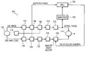
- FIG. 1illustrates a generalization of a circuit in which a differential delay may occur between aspects of an electromagnetic wave being processed by a system.
- processing system 100may include a source of an electromagnetic signal 102 , which may provide information regarding aspects of the wave, such as amplitude and phase, out along different signal paths.
- Each signal pathmay comprise one or more analog components ( 110 , 112 , and 122 ) and digital signal processing components ( 104 , 106 , 108 , 118 , and 120 ).
- Each of the digital processing componentsmay be timed from the same common clock source 116 .
- the amplitude and phase signalsstart out time aligned from source 102 .
- the timing of the signalsmay diverge as the signals traverse the various processing blocks.
- the signalsmay suffer from significant distortion.
- phase pathis shown as the dominant delay. However, those of ordinary skill in the art will appreciate that the converse is possible as well. If the phase is considered to be the dominant delay, then delay must be added to the amplitude path to equalize the paths. A digital delay adjust component 124 and an analog delay adjust component 126 may be added to perform this delay equalization.
- Phase_delay_totalAmp_delay_total+Digital_Delay_Adjust+Analog_Delay_Adjust.
- the delay caused by the digital blocksis determined primarily by clock 116 and is invariant over temperature, processing and voltage to within the tolerance of clock 116 , and so may be pre-determined. Also, any clock variability may be assumed to be applicable to both paths and may be normalized out.
- the difference in the amplitude and phase paths due to digital clockingmay be easily computed by taking the difference in the number of clock periods each signal takes through each path and then adding this difference to the amplitude path (in this example) using digital delay adjust component 124 .
- the mechanism used for digital delay adjust 124is not particularly limited, and may comprise, for example, one or more pipeline registers.
- Digital delay adjust 124may be hardwired to a fixed delay at the time of design or may be programmable for active adjustment of the delay compensation.
- the major cause of variations in delay over temperature, process, and voltagemay be attributable primarily to any analog components in the paths.
- Variations in the analog component pathsmay also be detected and compensated for using analog delay adjust 126 .
- Detection of the differential delaymay be performed by quantizing the phase signal just prior to the recombining in recombining circuit 126 and then comparing this quantized signal to the desired or expected phase response. In the illustrated embodiment, this may be accomplished using quantizer 128 and digital phase-locked loop (DPLL) 130 .
- DPLLdigital phase-locked loop
- DPLL 130may be used to perform an alignment of the expected phase and the actual phase signals.
- DPLL 130may receive the expected phase signal from an earlier digital processing component, in this example block 106 .
- Quantizer 128may receive the actual phase signal outputted from analog component 112 and produces a quantized signal representing the actual phase signal for inputting to DPLL 130 .
- DPLL 130receives this quantized, or sampled actual phase signal from quantizer 128 and produces a delay adjust control signal.
- the delay adjust control signalmay be based upon the magnitude of the delay variation.
- phase accumulator 164may be used to drive a phase accumulator 164 in a conventional manner to produce a reference signal representative of the expected phase for the processed output signal.
- the number of bits used in phase accumulator 164is not particularly limited. In the illustrated embodiment, the resolution of phase accumulator 164 (i.e, the number of bits) may be equal to that of quantizer 128 .
- Quantizer 128may be used to sample the actual phase signal. This function may be accomplished in any number of ways, such as by using an A/D converter, which would output a digital signal from quantizer 128 that contains the phase information of the modulated signal. Quantizer 128 may also use a timing signal from clock 116 in a conventional manner. The timing signal from clock 116 may also be incorporated into the digital signal outputted from quantizer 128 .
- This digital output from quantizer 128may then be inputted to DPLL 130 for comparison with the expected phase signal. For example, this digital signal may be subtracted from the “ideal” reference phase signal at subtractor 154 . Subtractor 154 may digitally subtract these two signals to produce an output that is a phase delay error signal, representative of the difference, or delay error, between the expected phase (which is substantially synchronized with the amplitude signal via clock 116 ) and the actual phase sampled by quantizer 128 .
- the delay error signalmay then be received by phase detector 144 , which may be operated to provide for a direct comparison of the digitally summed expected phase and the actual phase to produce a correction signal representing the amount of correction needed by analog delay adjust component 126 .
- the output of phase detector 144may be passed to decimator 156 , which may be used to reduce the sample rate of the loop filter in the DPLL.
- Decimator 156may comprise, for example, a cascaded integrator-comb filter (CIC) type, but is not limited thereto.
- Decimator 156then feeds loop filter 158 , which may comprise, for example an FIR filter having a predetermined response calculated for use with the signal being processed.
- the feedback output signal of loop filter 158may then be combined with the expected phase signal at subtractor 160 .
- the delay control signal outputted from DPLL 130may be received by analog delay adjust block 126 , which adds or subtracts the appropriate delay to the amplitude path.
- Analog delay adjust block 126is not particularly limited and may comprise any mechanism for adjusting the phase is the signal path, such as a bank of pipeline registers clocked at rate that is set high enough to provide the granularity to bring the amplitude and phase paths into alignment within the tolerance required by processing system 100 .
- a wave transmitter 300includes a baseband signal source 301 for receiving an input signal that contains intelligence (e.g., voice, data, etc.), an amplitude/phase signal processor 302 , wide-band phase modulator 321 , differential delay correction circuit 340 , delay adjuster 342 , power amplifier 305 .
- intelligencee.g., voice, data, etc.
- a phase modulated carrier wave from wideband phase modulator 321is passed to differential delay correction circuit 340 .
- differential delay correction circuit 340may be as shown in FIG. 2 , as previously described.
- Differential delay correction circuit 340quantizes the actual phase signal using quantizer 128 for comparison with the expected phase as received from amplitude/phase signal processor 302 . This may be accomplished using DPLL 130 , as previously described. DPLL 130 generates a correction signal based upon this comparison.
- This correction signalmay then be passed to delay adjuster 342 .
- delay adjuster 342is not particularly limited, but may comprise a bank of pipeline registers, for example.
- Delay adjuster 342adjusts the delay of amplitude component to reduce or eliminate its differential delay with phase component. In some modulation schemes, such as CDMA for example, it is preferably that the delay tolerance be less than about 10 ns.
- a transmitter, receiver, and/or transitive processing system of the inventionmay be specialized for particular input signals, carrier waves and output signals, e.g. various types of cell phones, such as CDMA, CDMA2000, W-CDMA, GSM, TDMA, as well as various other types of devices, both wired and wireless, e.g. Bluetooth, 802.11a, -b, -g, GPS, radar, 1xRTT, radios, GPRS, computers and computer communication devices, handheld devices, etc.
- GMSKwhich is used in GSM
- GFSKwhich is used in DECT & Bluetooth
- 8-PSKwhich is used in EDGE
- OQPSK & HPSKwhich are used in IS-2000
- p/4 DQPSKwhich is used in TDMA
- OFDMwhich is used in 802.11.
- the preferred embodimentsutilize both analog and digital components insofar as these embodiments manipulate waves and signals requiring both.
- cell phone embodimentsmay utilize both analog and digital components.
- Various types of system architecturesmay be utilized for constructing the embodiments.
- an ASIC compositionis used in realizing the various architectures.
- CMOS and/or BiCMOS fabrication techniquesmay be used as well as a combination of both, e.g. a BiCMOS Phase modulator area combined with a CMOS baseband area.
- transistor speedis a concern, and BiCMOS provides faster speed.
- BiCMOSprovides less current drain than an all CMOS configuration.
- the inventionimproves over the systems of the prior art.
- the ability to detect amplitude and phase delay mismatch and to adjustment of the delay to align the amplitude and phase pathsoccurs automatically while in operation substantially reduces expensive calibration time in the factory.
- This significant benefitis more pronounced since this scheme substantially eliminates the necessity of an embedded host controller, e.g., in a wireless handset, from having to perform a complex algorithm to align the two paths.
- this algorithmwould have to periodically recalibrate during a wireless phone call to account for significant temperature and voltage variations that can occur within a relatively short periods.
- the transmitter of the inventiondoes not include I/Q modulators, but instead preferably uses a polar modulation system.
- I/Q modulatorshave been used with linear modulation schemes. Not using such modulators eliminates the problem of I/Q imbalance that occurs when these modulators are used.
Landscapes
- Engineering & Computer Science (AREA)
- Computer Networks & Wireless Communication (AREA)
- Signal Processing (AREA)
- Amplifiers (AREA)
- Analogue/Digital Conversion (AREA)
Abstract
Description
Claims (25)
Priority Applications (3)
| Application Number | Priority Date | Filing Date | Title |
|---|---|---|---|
| US10/647,617US7254195B2 (en) | 2003-08-25 | 2003-08-25 | Apparatus, methods and articles of manufacture for dynamic differential delay correction |
| PCT/US2003/031983WO2004034606A2 (en) | 2002-10-08 | 2003-10-08 | Method and apparatus for dynamic differential delay correction in a transmission system |
| AU2003279902AAU2003279902A1 (en) | 2002-10-08 | 2003-10-08 | Method and apparatus for dynamic differential delay correction in a transmission system |
Applications Claiming Priority (1)
| Application Number | Priority Date | Filing Date | Title |
|---|---|---|---|
| US10/647,617US7254195B2 (en) | 2003-08-25 | 2003-08-25 | Apparatus, methods and articles of manufacture for dynamic differential delay correction |
Publications (2)
| Publication Number | Publication Date |
|---|---|
| US20050047532A1 US20050047532A1 (en) | 2005-03-03 |
| US7254195B2true US7254195B2 (en) | 2007-08-07 |
Family
ID=34225932
Family Applications (1)
| Application Number | Title | Priority Date | Filing Date |
|---|---|---|---|
| US10/647,617Expired - Fee RelatedUS7254195B2 (en) | 2002-10-08 | 2003-08-25 | Apparatus, methods and articles of manufacture for dynamic differential delay correction |
Country Status (1)
| Country | Link |
|---|---|
| US (1) | US7254195B2 (en) |
Cited By (4)
| Publication number | Priority date | Publication date | Assignee | Title |
|---|---|---|---|---|
| US20060246856A1 (en)* | 2003-08-07 | 2006-11-02 | Matsushita Electric Industrial Co., Ltd | Transmitter apparatus |
| US20110142177A1 (en)* | 2009-12-15 | 2011-06-16 | Electronics And Telecommunications Research Institute | Apparatus and method for compensating for delay mismatch between amplitude component signal and phase component signal |
| US20130251079A1 (en)* | 2010-11-24 | 2013-09-26 | Nec Corporation | Signal processing device, signal processing method and computer readable medium |
| US11283665B2 (en)* | 2017-01-04 | 2022-03-22 | Intel Corporation | Method and circuits for determining signal propagation time mismatches in a modulator |
Families Citing this family (4)
| Publication number | Priority date | Publication date | Assignee | Title |
|---|---|---|---|---|
| US7359680B2 (en)* | 2004-09-14 | 2008-04-15 | Telefonaktiebolaget Lm Ericsson (Publ) | Delay calibration in polar modulation transmitters |
| DE102006050879A1 (en)* | 2006-10-27 | 2008-05-08 | Infineon Technologies Ag | Phase-locked loop and method for generating an oscillator signal |
| TW201215145A (en)* | 2010-09-23 | 2012-04-01 | Hon Hai Prec Ind Co Ltd | Surveillance system |
| DE102011081689B4 (en) | 2011-08-26 | 2020-07-02 | Intel Deutschland Gmbh | SIGNAL PROCESSING DEVICE AND METHOD FOR PROVIDING A FIRST ANALOG SIGNAL AND A SECOND ANALOG SIGNAL |
Citations (88)
| Publication number | Priority date | Publication date | Assignee | Title |
|---|---|---|---|---|
| US4534040A (en) | 1983-01-04 | 1985-08-06 | At&T Information Systems | Method and apparatus for coding a binary signal |
| US4580111A (en) | 1981-12-24 | 1986-04-01 | Harris Corporation | Amplitude modulation using digitally selected carrier amplifiers |
| US4618999A (en)* | 1983-02-23 | 1986-10-21 | U.S. Philips Corporation | Polar loop transmitter |
| US4696017A (en)* | 1986-02-03 | 1987-09-22 | E-Systems, Inc. | Quadrature signal generator having digitally-controlled phase and amplitude correction |
| US4804931A (en) | 1987-12-11 | 1989-02-14 | Acrodyne Industries, Inc. | Digital amplitude modulator - transmitter |
| US4947455A (en) | 1988-11-09 | 1990-08-07 | Harris Corporation | RF power supply for supplying a regulated power amplified unmodulated drive signal to an RF modulator |
| US4952890A (en) | 1989-09-12 | 1990-08-28 | Harris Corporation | Phase modulation compensated amplitude modulator using digitally selected amplifiers |
| US5056109A (en) | 1989-11-07 | 1991-10-08 | Qualcomm, Inc. | Method and apparatus for controlling transmission power in a cdma cellular mobile telephone system |
| US5257283A (en) | 1989-11-07 | 1993-10-26 | Qualcomm Incorporated | Spread spectrum transmitter power control method and system |
| US5265119A (en) | 1989-11-07 | 1993-11-23 | Qualcomm Incorporated | Method and apparatus for controlling transmission power in a CDMA cellular mobile telephone system |
| US5267262A (en) | 1989-11-07 | 1993-11-30 | Qualcomm Incorporated | Transmitter power control system |
| US5367272A (en) | 1992-08-04 | 1994-11-22 | Acrodyne Industries, Inc. | Digital amplitude modulators involving (1) modification of amplitude during synchronization pulse, (2) automatic gain control of signal components, and/or (3) analog representation of less significant signal components |
| US5392007A (en) | 1994-04-12 | 1995-02-21 | Harris Corporation | Modulator having improved encoding |
| US5396516A (en) | 1993-02-22 | 1995-03-07 | Qualcomm Incorporated | Method and system for the dynamic modification of control paremeters in a transmitter power control system |
| US5450044A (en) | 1993-04-14 | 1995-09-12 | Acrodyne Industries, Inc. | Quadrature amplitude modulator including a digital amplitude modulator as a component thereof |
| US5452473A (en) | 1994-02-28 | 1995-09-19 | Qualcomm Incorporated | Reverse link, transmit power correction and limitation in a radiotelephone system |
| US5469127A (en) | 1992-08-04 | 1995-11-21 | Acrodyne Industries, Inc. | Amplification apparatus and method including modulator component |
| US5485486A (en) | 1989-11-07 | 1996-01-16 | Qualcomm Incorporated | Method and apparatus for controlling transmission power in a CDMA cellular mobile telephone system |
| US5524286A (en) | 1993-12-14 | 1996-06-04 | Alcatel Italia S.P.A. | Baseband predistortion system for the adaptive linearization of power amplifiers |
| US5598436A (en) | 1993-06-29 | 1997-01-28 | U.S. Philips Corporation | Digital transmission system with predistortion |
| US5621351A (en) | 1993-03-04 | 1997-04-15 | Thomcast Ag | Modulation amplifier for radio transmitters |
| US5661434A (en) | 1995-05-12 | 1997-08-26 | Fujitsu Compound Semiconductor, Inc. | High efficiency multiple power level amplifier circuit |
| US5703902A (en) | 1995-06-16 | 1997-12-30 | Qualcomm Incorporated | Method and apparatus for determining signal strength in a variable data rate system |
| US5758269A (en) | 1995-03-30 | 1998-05-26 | Lucent Technologies Inc. | High-efficient configurable power amplifier for use in a portable unit |
| US5867071A (en) | 1997-08-15 | 1999-02-02 | Lockheed Martin Aerospace Corp. | High power transmitter employing a high power QAM modulator |
| US5886573A (en) | 1998-03-06 | 1999-03-23 | Fujant, Inc. | Amplification using amplitude reconstruction of amplitude and/or angle modulated carrier |
| US5903554A (en) | 1996-09-27 | 1999-05-11 | Qualcomm Incorporation | Method and apparatus for measuring link quality in a spread spectrum communication system |
| US5905760A (en) | 1996-03-22 | 1999-05-18 | Matra Communication | Method of correcting nonlinearities of an amplifier, and radio transmitter employing a method of this type |
| US5974041A (en) | 1995-12-27 | 1999-10-26 | Qualcomm Incorporated | Efficient parallel-stage power amplifier |
| US6041082A (en) | 1996-09-06 | 2000-03-21 | Nec Corporation | Digital amplitude modulation amplifier and television broadcasting machine |
| US6043707A (en) | 1999-01-07 | 2000-03-28 | Motorola, Inc. | Method and apparatus for operating a radio-frequency power amplifier as a variable-class linear amplifier |
| US6075974A (en) | 1996-11-20 | 2000-06-13 | Qualcomm Inc. | Method and apparatus for adjusting thresholds and measurements of received signals by anticipating power control commands yet to be executed |
| US6125266A (en) | 1997-12-31 | 2000-09-26 | Nokia Mobile Phones Limited | Dual band architectures for mobile stations having transmitter linearization feedback |
| US6160444A (en)* | 1993-09-29 | 2000-12-12 | Stmicroelectronics Of The United Kingdom | Demodulation of FM audio carrier |
| US6178313B1 (en) | 1998-12-31 | 2001-01-23 | Nokia Mobile Phones Limited | Control of gain and power consumption in a power amplifier |
| US6185432B1 (en) | 1997-10-13 | 2001-02-06 | Qualcomm Incorporated | System and method for selecting power control modes |
| US6191653B1 (en) | 1998-11-18 | 2001-02-20 | Ericsson Inc. | Circuit and method for linearizing amplitude modulation in a power amplifier |
| US6194963B1 (en) | 1998-11-18 | 2001-02-27 | Ericsson Inc. | Circuit and method for I/Q modulation with independent, high efficiency amplitude modulation |
| US6256482B1 (en) | 1997-04-07 | 2001-07-03 | Frederick H. Raab | Power- conserving drive-modulation method for envelope-elimination-and-restoration (EER) transmitters |
| US6255906B1 (en) | 1999-09-30 | 2001-07-03 | Conexant Systems, Inc. | Power amplifier operated as an envelope digital to analog converter with digital pre-distortion |
| US6259928B1 (en) | 1997-10-13 | 2001-07-10 | Qualcomm Inc. | System and method for optimized power control |
| US6272336B1 (en) | 1998-12-30 | 2001-08-07 | Samsung Electronics Co., Ltd. | Traffic-weighted closed loop power detection system for use with an RF power amplifier and method of operation |
| US6275685B1 (en)* | 1998-12-10 | 2001-08-14 | Nortel Networks Limited | Linear amplifier arrangement |
| US6295442B1 (en)* | 1998-12-07 | 2001-09-25 | Ericsson Inc. | Amplitude modulation to phase modulation cancellation method in an RF amplifier |
| WO2001076169A1 (en) | 2000-03-31 | 2001-10-11 | Nortel Networks France | Device for producing a phase and amplitude modulated radio frequency signal |
| USRE37407E1 (en)* | 1996-01-30 | 2001-10-16 | Spectrian Corporation | Polar envelope correction mechanism for enhancing linearity of RF/microwave power amplifier |
| US6320913B1 (en) | 1997-06-23 | 2001-11-20 | Nec Corporation | Circuit and method for controlling transmission amplifiers |
| US6330462B1 (en) | 1997-07-01 | 2001-12-11 | Qualcomm Incorporated | Method and apparatus for pre-transmission power control using lower rate for high rate communication |
| US6351650B1 (en) | 1999-01-28 | 2002-02-26 | Qualcomm Incorporated | System and method for forward link power balancing in a wireless communication system |
| US6370109B1 (en) | 1999-03-10 | 2002-04-09 | Qualcomm Incorporated | CDMA signal power control using quadrature signal calculations |
| US6377784B2 (en) | 1999-02-09 | 2002-04-23 | Tropian, Inc. | High-efficiency modulation RF amplifier |
| US6381292B1 (en)* | 1997-12-19 | 2002-04-30 | Sony Corporation | Phase synchronizing apparatus, phase synchronizing method and disc drive |
| US20020071497A1 (en)* | 2000-10-31 | 2002-06-13 | Erik Bengtsson | IQ modulation systems and methods that use separate phase and amplitude signal paths and perform modulation within a phase locked loop |
| EP1217753A1 (en) | 2000-12-15 | 2002-06-26 | Nokia Corporation | Linear RF power amplifier and transmitter |
| US20020090921A1 (en) | 2000-12-22 | 2002-07-11 | Jacob Midtgaard | Transmitter circuits |
| US6421327B1 (en) | 1999-06-28 | 2002-07-16 | Qualcomm Incorporated | Method and apparatus for controlling transmission energy in a communication system employing orthogonal transmit diversity |
| US20020098812A1 (en) | 2001-01-25 | 2002-07-25 | Essam Sourour | Amplifier phase change compensation |
| US6449465B1 (en)* | 1999-12-20 | 2002-09-10 | Motorola, Inc. | Method and apparatus for linear amplification of a radio frequency signal |
| US20020141510A1 (en) | 2001-03-28 | 2002-10-03 | Ashvattha Semiconductor, Inc. | Method of and apparatus for performing modulation |
| US6490460B1 (en) | 1998-12-01 | 2002-12-03 | Qualcomm Incorporated | Forward and reverse link power control using position and mobility information |
| US20020186783A1 (en) | 2001-06-07 | 2002-12-12 | Motorola, Inc | Amplifier predistortion system and method |
| US20020193085A1 (en) | 2001-06-15 | 2002-12-19 | Telefonaktiebolaget Lm Ericsson | Systems and methods for amplification of a communication signal |
| US6512417B2 (en)* | 2000-05-11 | 2003-01-28 | Nortel Networks Limited | Linear amplifier arrangement |
| US6539068B2 (en)* | 1997-05-22 | 2003-03-25 | Conexant Systems, Inc. | Receiver of wideband digital signal in the presence of a narrow band interfering signal |
| US20030073419A1 (en) | 2001-10-10 | 2003-04-17 | Zarlink Semiconductor Limited | Power control in polar loop transmitters |
| US20030095608A1 (en) | 2001-11-16 | 2003-05-22 | Koninklijke Philips Electronics N.V. | Transmitter with transmitter chain phase adjustment on the basis of pre-stored phase information |
| US6621340B1 (en) | 2000-02-24 | 2003-09-16 | Fraunhofer-Gesellschaft zur Förderung der angewandten Forschung e.V. | System for reducing adjacent-channel interference by pre-linearization and pre-distortion |
| US6628165B1 (en) | 2000-11-07 | 2003-09-30 | Linear Technology Corporation | Power controllers for amplitude modulation |
| US6636112B1 (en) | 1999-07-29 | 2003-10-21 | Tropian, Inc. | High-efficiency modulating RF amplifier |
| US20030215026A1 (en) | 2002-05-16 | 2003-11-20 | Hietala Alexander Wayne | AM to AM correction system for polar modulator |
| US20030215025A1 (en) | 2002-05-16 | 2003-11-20 | Hietala Alexander Wayne | AM to PM correction system for polar modulator |
| US6658238B1 (en) | 1998-07-10 | 2003-12-02 | Thomson-Csf | Method for elaborating a transmission signal and transmitter with amplifying cells for implementing same |
| US20030223510A1 (en) | 2002-05-31 | 2003-12-04 | Noriyuki Kurakami | Semiconductor integrated circuit for communication, radio-communications apparatus, and transmission starting method |
| US20040021517A1 (en) | 2002-08-05 | 2004-02-05 | Spectrian Corporation | Power minimization, correlation-based closed loop for controlling predistorter and vector modulator feeding RF power amplifier |
| US6701134B1 (en) | 2002-11-05 | 2004-03-02 | Rf Micro Devices, Inc. | Increased dynamic range for power amplifiers used with polar modulation |
| US6703897B2 (en)* | 2001-12-26 | 2004-03-09 | Nortel Networks Limited | Methods of optimising power amplifier efficiency and closed-loop power amplifier controllers |
| US20040047432A1 (en) | 2002-06-28 | 2004-03-11 | Nec Corporation | Nonlinear distortion compensating circuit |
| US6738432B2 (en) | 2001-03-21 | 2004-05-18 | Ericsson Inc. | System and method for RF signal amplification |
| US6791417B2 (en) | 2002-01-28 | 2004-09-14 | Cree Microwave, Inc. | N-way RF power amplifier circuit with increased back-off capability and power added efficiency using selected phase lengths and output impedances |
| US6799020B1 (en) | 1999-07-20 | 2004-09-28 | Qualcomm Incorporated | Parallel amplifier architecture using digital phase control techniques |
| US20040192369A1 (en) | 2002-08-08 | 2004-09-30 | Magnus Nilsson | Method and apparatus for reducing dynamic range of a power amplifier |
| US6816008B2 (en) | 2002-12-31 | 2004-11-09 | Alion Science And Technology Corporation | Quasi-linear multi-state digital modulation through non-linear amplifier arrays |
| US6834084B2 (en) | 2002-05-06 | 2004-12-21 | Rf Micro Devices Inc | Direct digital polar modulator |
| US20050017801A1 (en) | 2003-07-23 | 2005-01-27 | Andrew Corporation | Elimination of peak clipping and improved efficiency for RF power amplifiers with a predistorter |
| US20050030104A1 (en) | 2003-08-07 | 2005-02-10 | Ntt Docomo, Inc. | Power amplifier |
| US20050118965A1 (en) | 2003-12-02 | 2005-06-02 | Matsushita Electric Industrial Co., Ltd. | Signal transmitter |
| US20050122164A1 (en) | 2003-12-05 | 2005-06-09 | Per-Olof Brandt | Single chip power amplifier and envelope modulator |
| US6993087B2 (en)* | 2001-06-29 | 2006-01-31 | Nokia Mobile Phones Ltd. | Switching mode power amplifier using PWM and PPM for bandpass signals |
- 2003
- 2003-08-25USUS10/647,617patent/US7254195B2/ennot_activeExpired - Fee Related
Patent Citations (92)
| Publication number | Priority date | Publication date | Assignee | Title |
|---|---|---|---|---|
| US4580111A (en) | 1981-12-24 | 1986-04-01 | Harris Corporation | Amplitude modulation using digitally selected carrier amplifiers |
| US4534040A (en) | 1983-01-04 | 1985-08-06 | At&T Information Systems | Method and apparatus for coding a binary signal |
| US4618999A (en)* | 1983-02-23 | 1986-10-21 | U.S. Philips Corporation | Polar loop transmitter |
| US4696017A (en)* | 1986-02-03 | 1987-09-22 | E-Systems, Inc. | Quadrature signal generator having digitally-controlled phase and amplitude correction |
| US4804931A (en) | 1987-12-11 | 1989-02-14 | Acrodyne Industries, Inc. | Digital amplitude modulator - transmitter |
| US4947455A (en) | 1988-11-09 | 1990-08-07 | Harris Corporation | RF power supply for supplying a regulated power amplified unmodulated drive signal to an RF modulator |
| US4952890A (en) | 1989-09-12 | 1990-08-28 | Harris Corporation | Phase modulation compensated amplitude modulator using digitally selected amplifiers |
| US5257283A (en) | 1989-11-07 | 1993-10-26 | Qualcomm Incorporated | Spread spectrum transmitter power control method and system |
| US5265119A (en) | 1989-11-07 | 1993-11-23 | Qualcomm Incorporated | Method and apparatus for controlling transmission power in a CDMA cellular mobile telephone system |
| US5267262A (en) | 1989-11-07 | 1993-11-30 | Qualcomm Incorporated | Transmitter power control system |
| US5056109A (en) | 1989-11-07 | 1991-10-08 | Qualcomm, Inc. | Method and apparatus for controlling transmission power in a cdma cellular mobile telephone system |
| US5485486A (en) | 1989-11-07 | 1996-01-16 | Qualcomm Incorporated | Method and apparatus for controlling transmission power in a CDMA cellular mobile telephone system |
| US5367272A (en) | 1992-08-04 | 1994-11-22 | Acrodyne Industries, Inc. | Digital amplitude modulators involving (1) modification of amplitude during synchronization pulse, (2) automatic gain control of signal components, and/or (3) analog representation of less significant signal components |
| US5469127A (en) | 1992-08-04 | 1995-11-21 | Acrodyne Industries, Inc. | Amplification apparatus and method including modulator component |
| US5396516A (en) | 1993-02-22 | 1995-03-07 | Qualcomm Incorporated | Method and system for the dynamic modification of control paremeters in a transmitter power control system |
| US5621351A (en) | 1993-03-04 | 1997-04-15 | Thomcast Ag | Modulation amplifier for radio transmitters |
| US5450044A (en) | 1993-04-14 | 1995-09-12 | Acrodyne Industries, Inc. | Quadrature amplitude modulator including a digital amplitude modulator as a component thereof |
| US5598436A (en) | 1993-06-29 | 1997-01-28 | U.S. Philips Corporation | Digital transmission system with predistortion |
| US6160444A (en)* | 1993-09-29 | 2000-12-12 | Stmicroelectronics Of The United Kingdom | Demodulation of FM audio carrier |
| US5524286A (en) | 1993-12-14 | 1996-06-04 | Alcatel Italia S.P.A. | Baseband predistortion system for the adaptive linearization of power amplifiers |
| US5590408A (en) | 1994-02-28 | 1996-12-31 | Qualcomm Incorporated | Reverse link, transmit power correction and limitation in a radiotelephone system |
| US5655220A (en) | 1994-02-28 | 1997-08-05 | Qualcomm Incorporated | Reverse link, transmit power correction and limitation in a radiotelephone system |
| US5452473A (en) | 1994-02-28 | 1995-09-19 | Qualcomm Incorporated | Reverse link, transmit power correction and limitation in a radiotelephone system |
| US5392007A (en) | 1994-04-12 | 1995-02-21 | Harris Corporation | Modulator having improved encoding |
| US5758269A (en) | 1995-03-30 | 1998-05-26 | Lucent Technologies Inc. | High-efficient configurable power amplifier for use in a portable unit |
| US5661434A (en) | 1995-05-12 | 1997-08-26 | Fujitsu Compound Semiconductor, Inc. | High efficiency multiple power level amplifier circuit |
| US5703902A (en) | 1995-06-16 | 1997-12-30 | Qualcomm Incorporated | Method and apparatus for determining signal strength in a variable data rate system |
| US5974041A (en) | 1995-12-27 | 1999-10-26 | Qualcomm Incorporated | Efficient parallel-stage power amplifier |
| USRE37407E1 (en)* | 1996-01-30 | 2001-10-16 | Spectrian Corporation | Polar envelope correction mechanism for enhancing linearity of RF/microwave power amplifier |
| US5905760A (en) | 1996-03-22 | 1999-05-18 | Matra Communication | Method of correcting nonlinearities of an amplifier, and radio transmitter employing a method of this type |
| US6041082A (en) | 1996-09-06 | 2000-03-21 | Nec Corporation | Digital amplitude modulation amplifier and television broadcasting machine |
| US5903554A (en) | 1996-09-27 | 1999-05-11 | Qualcomm Incorporation | Method and apparatus for measuring link quality in a spread spectrum communication system |
| US6075974A (en) | 1996-11-20 | 2000-06-13 | Qualcomm Inc. | Method and apparatus for adjusting thresholds and measurements of received signals by anticipating power control commands yet to be executed |
| US6374085B1 (en) | 1996-11-20 | 2002-04-16 | Qualcomm Incorporated | Method and apparatus for adjusting thresholds and measurements of received signals by anticipating power control commands yet to be executed |
| US6256482B1 (en) | 1997-04-07 | 2001-07-03 | Frederick H. Raab | Power- conserving drive-modulation method for envelope-elimination-and-restoration (EER) transmitters |
| US6539068B2 (en)* | 1997-05-22 | 2003-03-25 | Conexant Systems, Inc. | Receiver of wideband digital signal in the presence of a narrow band interfering signal |
| US6320913B1 (en) | 1997-06-23 | 2001-11-20 | Nec Corporation | Circuit and method for controlling transmission amplifiers |
| US6330462B1 (en) | 1997-07-01 | 2001-12-11 | Qualcomm Incorporated | Method and apparatus for pre-transmission power control using lower rate for high rate communication |
| US5867071A (en) | 1997-08-15 | 1999-02-02 | Lockheed Martin Aerospace Corp. | High power transmitter employing a high power QAM modulator |
| US6185432B1 (en) | 1997-10-13 | 2001-02-06 | Qualcomm Incorporated | System and method for selecting power control modes |
| US6259928B1 (en) | 1997-10-13 | 2001-07-10 | Qualcomm Inc. | System and method for optimized power control |
| US6381292B1 (en)* | 1997-12-19 | 2002-04-30 | Sony Corporation | Phase synchronizing apparatus, phase synchronizing method and disc drive |
| US6125266A (en) | 1997-12-31 | 2000-09-26 | Nokia Mobile Phones Limited | Dual band architectures for mobile stations having transmitter linearization feedback |
| US6147553A (en) | 1998-03-06 | 2000-11-14 | Fujant, Inc. | Amplification using amplitude reconstruction of amplitude and/or angle modulated carrier |
| US5886573A (en) | 1998-03-06 | 1999-03-23 | Fujant, Inc. | Amplification using amplitude reconstruction of amplitude and/or angle modulated carrier |
| US6658238B1 (en) | 1998-07-10 | 2003-12-02 | Thomson-Csf | Method for elaborating a transmission signal and transmitter with amplifying cells for implementing same |
| US6194963B1 (en) | 1998-11-18 | 2001-02-27 | Ericsson Inc. | Circuit and method for I/Q modulation with independent, high efficiency amplitude modulation |
| US6191653B1 (en) | 1998-11-18 | 2001-02-20 | Ericsson Inc. | Circuit and method for linearizing amplitude modulation in a power amplifier |
| US6490460B1 (en) | 1998-12-01 | 2002-12-03 | Qualcomm Incorporated | Forward and reverse link power control using position and mobility information |
| US6295442B1 (en)* | 1998-12-07 | 2001-09-25 | Ericsson Inc. | Amplitude modulation to phase modulation cancellation method in an RF amplifier |
| US6275685B1 (en)* | 1998-12-10 | 2001-08-14 | Nortel Networks Limited | Linear amplifier arrangement |
| US6272336B1 (en) | 1998-12-30 | 2001-08-07 | Samsung Electronics Co., Ltd. | Traffic-weighted closed loop power detection system for use with an RF power amplifier and method of operation |
| US6178313B1 (en) | 1998-12-31 | 2001-01-23 | Nokia Mobile Phones Limited | Control of gain and power consumption in a power amplifier |
| US6043707A (en) | 1999-01-07 | 2000-03-28 | Motorola, Inc. | Method and apparatus for operating a radio-frequency power amplifier as a variable-class linear amplifier |
| US6351650B1 (en) | 1999-01-28 | 2002-02-26 | Qualcomm Incorporated | System and method for forward link power balancing in a wireless communication system |
| US6377784B2 (en) | 1999-02-09 | 2002-04-23 | Tropian, Inc. | High-efficiency modulation RF amplifier |
| US6370109B1 (en) | 1999-03-10 | 2002-04-09 | Qualcomm Incorporated | CDMA signal power control using quadrature signal calculations |
| US6421327B1 (en) | 1999-06-28 | 2002-07-16 | Qualcomm Incorporated | Method and apparatus for controlling transmission energy in a communication system employing orthogonal transmit diversity |
| US6799020B1 (en) | 1999-07-20 | 2004-09-28 | Qualcomm Incorporated | Parallel amplifier architecture using digital phase control techniques |
| US6636112B1 (en) | 1999-07-29 | 2003-10-21 | Tropian, Inc. | High-efficiency modulating RF amplifier |
| US6255906B1 (en) | 1999-09-30 | 2001-07-03 | Conexant Systems, Inc. | Power amplifier operated as an envelope digital to analog converter with digital pre-distortion |
| US6449465B1 (en)* | 1999-12-20 | 2002-09-10 | Motorola, Inc. | Method and apparatus for linear amplification of a radio frequency signal |
| US6621340B1 (en) | 2000-02-24 | 2003-09-16 | Fraunhofer-Gesellschaft zur Förderung der angewandten Forschung e.V. | System for reducing adjacent-channel interference by pre-linearization and pre-distortion |
| WO2001076169A1 (en) | 2000-03-31 | 2001-10-11 | Nortel Networks France | Device for producing a phase and amplitude modulated radio frequency signal |
| US6512417B2 (en)* | 2000-05-11 | 2003-01-28 | Nortel Networks Limited | Linear amplifier arrangement |
| US20020071497A1 (en)* | 2000-10-31 | 2002-06-13 | Erik Bengtsson | IQ modulation systems and methods that use separate phase and amplitude signal paths and perform modulation within a phase locked loop |
| US6628165B1 (en) | 2000-11-07 | 2003-09-30 | Linear Technology Corporation | Power controllers for amplitude modulation |
| EP1217753A1 (en) | 2000-12-15 | 2002-06-26 | Nokia Corporation | Linear RF power amplifier and transmitter |
| US20020090921A1 (en) | 2000-12-22 | 2002-07-11 | Jacob Midtgaard | Transmitter circuits |
| US20020098812A1 (en) | 2001-01-25 | 2002-07-25 | Essam Sourour | Amplifier phase change compensation |
| US6738432B2 (en) | 2001-03-21 | 2004-05-18 | Ericsson Inc. | System and method for RF signal amplification |
| US20020141510A1 (en) | 2001-03-28 | 2002-10-03 | Ashvattha Semiconductor, Inc. | Method of and apparatus for performing modulation |
| US20020186783A1 (en) | 2001-06-07 | 2002-12-12 | Motorola, Inc | Amplifier predistortion system and method |
| US20020193085A1 (en) | 2001-06-15 | 2002-12-19 | Telefonaktiebolaget Lm Ericsson | Systems and methods for amplification of a communication signal |
| US6993087B2 (en)* | 2001-06-29 | 2006-01-31 | Nokia Mobile Phones Ltd. | Switching mode power amplifier using PWM and PPM for bandpass signals |
| US20030073419A1 (en) | 2001-10-10 | 2003-04-17 | Zarlink Semiconductor Limited | Power control in polar loop transmitters |
| US20030095608A1 (en) | 2001-11-16 | 2003-05-22 | Koninklijke Philips Electronics N.V. | Transmitter with transmitter chain phase adjustment on the basis of pre-stored phase information |
| US6703897B2 (en)* | 2001-12-26 | 2004-03-09 | Nortel Networks Limited | Methods of optimising power amplifier efficiency and closed-loop power amplifier controllers |
| US6791417B2 (en) | 2002-01-28 | 2004-09-14 | Cree Microwave, Inc. | N-way RF power amplifier circuit with increased back-off capability and power added efficiency using selected phase lengths and output impedances |
| US6834084B2 (en) | 2002-05-06 | 2004-12-21 | Rf Micro Devices Inc | Direct digital polar modulator |
| US20030215026A1 (en) | 2002-05-16 | 2003-11-20 | Hietala Alexander Wayne | AM to AM correction system for polar modulator |
| US20030215025A1 (en) | 2002-05-16 | 2003-11-20 | Hietala Alexander Wayne | AM to PM correction system for polar modulator |
| US20030223510A1 (en) | 2002-05-31 | 2003-12-04 | Noriyuki Kurakami | Semiconductor integrated circuit for communication, radio-communications apparatus, and transmission starting method |
| US20040047432A1 (en) | 2002-06-28 | 2004-03-11 | Nec Corporation | Nonlinear distortion compensating circuit |
| US20040021517A1 (en) | 2002-08-05 | 2004-02-05 | Spectrian Corporation | Power minimization, correlation-based closed loop for controlling predistorter and vector modulator feeding RF power amplifier |
| US20040192369A1 (en) | 2002-08-08 | 2004-09-30 | Magnus Nilsson | Method and apparatus for reducing dynamic range of a power amplifier |
| US6701134B1 (en) | 2002-11-05 | 2004-03-02 | Rf Micro Devices, Inc. | Increased dynamic range for power amplifiers used with polar modulation |
| US6816008B2 (en) | 2002-12-31 | 2004-11-09 | Alion Science And Technology Corporation | Quasi-linear multi-state digital modulation through non-linear amplifier arrays |
| US20050017801A1 (en) | 2003-07-23 | 2005-01-27 | Andrew Corporation | Elimination of peak clipping and improved efficiency for RF power amplifiers with a predistorter |
| US20050030104A1 (en) | 2003-08-07 | 2005-02-10 | Ntt Docomo, Inc. | Power amplifier |
| US20050118965A1 (en) | 2003-12-02 | 2005-06-02 | Matsushita Electric Industrial Co., Ltd. | Signal transmitter |
| US20050122164A1 (en) | 2003-12-05 | 2005-06-09 | Per-Olof Brandt | Single chip power amplifier and envelope modulator |
Cited By (7)
| Publication number | Priority date | Publication date | Assignee | Title |
|---|---|---|---|---|
| US20060246856A1 (en)* | 2003-08-07 | 2006-11-02 | Matsushita Electric Industrial Co., Ltd | Transmitter apparatus |
| US7379715B2 (en)* | 2003-08-07 | 2008-05-27 | Matsushita Electric Industrial Co., Ltd. | Transmitter apparatus and method using polar modulation with signal timing adjustment |
| US20110142177A1 (en)* | 2009-12-15 | 2011-06-16 | Electronics And Telecommunications Research Institute | Apparatus and method for compensating for delay mismatch between amplitude component signal and phase component signal |
| US8514972B2 (en)* | 2009-12-15 | 2013-08-20 | Electronics And Telecommunications Research Institute | Apparatus and method for compensating for delay mismatch between amplitude component signal and phase component signal |
| US20130251079A1 (en)* | 2010-11-24 | 2013-09-26 | Nec Corporation | Signal processing device, signal processing method and computer readable medium |
| US9030240B2 (en)* | 2010-11-24 | 2015-05-12 | Nec Corporation | Signal processing device, signal processing method and computer readable medium |
| US11283665B2 (en)* | 2017-01-04 | 2022-03-22 | Intel Corporation | Method and circuits for determining signal propagation time mismatches in a modulator |
Also Published As
| Publication number | Publication date |
|---|---|
| US20050047532A1 (en) | 2005-03-03 |
Similar Documents
| Publication | Publication Date | Title |
|---|---|---|
| US7991071B2 (en) | AM to PM correction system for polar modulator | |
| US7933569B2 (en) | Timing adjustment method for wireless communication apparatus | |
| JP4071526B2 (en) | Nonlinear distortion compensation apparatus and transmission apparatus | |
| US7072420B2 (en) | Communications systems | |
| US20030215026A1 (en) | AM to AM correction system for polar modulator | |
| US6621876B2 (en) | System and method to reduce phase modulation bandwidth | |
| KR20000035043A (en) | Digital feedforward amplifier for use in an rf transmitter and method of operation | |
| WO2006118317A1 (en) | Polar modulation transmitter circuit and communications device | |
| US5577027A (en) | Apparatus and method for effectively eliminating the echo signal of transmitting signal in a modem | |
| US7254195B2 (en) | Apparatus, methods and articles of manufacture for dynamic differential delay correction | |
| EP0898809A1 (en) | Pre-post distortion amplifier | |
| US7502422B2 (en) | Electromagnetic wave transmitter systems, methods and articles of manufacture | |
| US5799034A (en) | Frequency acquisition method for direct sequence spread spectrum systems | |
| US6903619B2 (en) | Electromagnetic wave transmitter systems, methods and articles of manufacture | |
| US7457586B1 (en) | Method of in-device phase measurement and correlation to programmable factors | |
| US6870435B2 (en) | Electromagnetic wave transmitter, receiver and transceiver systems, methods and articles of manufacture | |
| US7551685B2 (en) | Apparatus, methods and articles of manufacture for signal correction using adaptive phase re-alignment | |
| US7251463B2 (en) | Methods and apparatus for controlling signals | |
| US7274748B1 (en) | AM to FM correction system for a polar modulator | |
| US8532590B2 (en) | Digital phase feedback for determining phase distortion | |
| WO2004034606A2 (en) | Method and apparatus for dynamic differential delay correction in a transmission system | |
| JP2012175708A (en) | Predistortion device | |
| US8224265B1 (en) | Method for optimizing AM/AM and AM/PM predistortion in a mobile terminal | |
| JP2006502682A (en) | Transmitter and method of transmission using independent phase and amplitude modulators | |
| US7545865B2 (en) | Apparatus, methods and articles of manufacture for wideband signal processing |
Legal Events
| Date | Code | Title | Description |
|---|---|---|---|
| AS | Assignment | Owner name:M/A-COM, INC., MASSACHUSETTS Free format text:ASSIGNMENT OF ASSIGNORS INTEREST;ASSIGNORS:SERVILIO, ROBERT;MOY, CAROL;DIVINCENZO, CHRISTINE;AND OTHERS;REEL/FRAME:014642/0900 Effective date:20031023 | |
| AS | Assignment | Owner name:PINE VALLEY INVESTMENTS, INC., NEVADA Free format text:ASSIGNMENT OF ASSIGNORS INTEREST;ASSIGNORS:TYCO ELECTRONICS GROUP S.A.;TYCO ELECTRONICS CORPORATION;THE WHITAKER CORPORATION;AND OTHERS;REEL/FRAME:023065/0269 Effective date:20090529 Owner name:PINE VALLEY INVESTMENTS, INC.,NEVADA Free format text:ASSIGNMENT OF ASSIGNORS INTEREST;ASSIGNORS:TYCO ELECTRONICS GROUP S.A.;TYCO ELECTRONICS CORPORATION;THE WHITAKER CORPORATION;AND OTHERS;REEL/FRAME:023065/0269 Effective date:20090529 | |
| FPAY | Fee payment | Year of fee payment:4 | |
| AS | Assignment | Owner name:HARRIS CORPORATION, FLORIDA Free format text:ASSIGNMENT OF ASSIGNORS INTEREST;ASSIGNOR:PINE VALLEY INVESTMENTS, LLC;REEL/FRAME:027529/0160 Effective date:20120112 | |
| AS | Assignment | Owner name:NORTH SOUTH HOLDINGS INC., NEW YORK Free format text:ASSIGNMENT OF ASSIGNORS INTEREST;ASSIGNOR:HARRIS CORPORATION;REEL/FRAME:030119/0804 Effective date:20130107 | |
| REMI | Maintenance fee reminder mailed | ||
| LAPS | Lapse for failure to pay maintenance fees | ||
| STCH | Information on status: patent discontinuation | Free format text:PATENT EXPIRED DUE TO NONPAYMENT OF MAINTENANCE FEES UNDER 37 CFR 1.362 | |
| FP | Lapsed due to failure to pay maintenance fee | Effective date:20150807 |