US7253802B2 - User interface - Google Patents
User interfaceDownload PDFInfo
- Publication number
- US7253802B2 US7253802B2US11/055,774US5577405AUS7253802B2US 7253802 B2US7253802 B2US 7253802B2US 5577405 AUS5577405 AUS 5577405AUS 7253802 B2US7253802 B2US 7253802B2
- Authority
- US
- United States
- Prior art keywords
- electronic device
- configuration
- input
- input means
- state
- Prior art date
- Legal status (The legal status is an assumption and is not a legal conclusion. Google has not performed a legal analysis and makes no representation as to the accuracy of the status listed.)
- Expired - Lifetime
Links
Images


Classifications
- G—PHYSICS
- G09—EDUCATION; CRYPTOGRAPHY; DISPLAY; ADVERTISING; SEALS
- G09F—DISPLAYING; ADVERTISING; SIGNS; LABELS OR NAME-PLATES; SEALS
- G09F9/00—Indicating arrangements for variable information in which the information is built-up on a support by selection or combination of individual elements
- G09F9/30—Indicating arrangements for variable information in which the information is built-up on a support by selection or combination of individual elements in which the desired character or characters are formed by combining individual elements
- G—PHYSICS
- G06—COMPUTING OR CALCULATING; COUNTING
- G06F—ELECTRIC DIGITAL DATA PROCESSING
- G06F1/00—Details not covered by groups G06F3/00 - G06F13/00 and G06F21/00
- G06F1/16—Constructional details or arrangements
- G06F1/1613—Constructional details or arrangements for portable computers
- G06F1/1615—Constructional details or arrangements for portable computers with several enclosures having relative motions, each enclosure supporting at least one I/O or computing function
- G—PHYSICS
- G06—COMPUTING OR CALCULATING; COUNTING
- G06F—ELECTRIC DIGITAL DATA PROCESSING
- G06F1/00—Details not covered by groups G06F3/00 - G06F13/00 and G06F21/00
- G06F1/16—Constructional details or arrangements
- G06F1/1613—Constructional details or arrangements for portable computers
- G06F1/1633—Constructional details or arrangements of portable computers not specific to the type of enclosures covered by groups G06F1/1615 - G06F1/1626
- G06F1/1637—Details related to the display arrangement, including those related to the mounting of the display in the housing
- G06F1/1652—Details related to the display arrangement, including those related to the mounting of the display in the housing the display being flexible, e.g. mimicking a sheet of paper, or rollable
- G—PHYSICS
- G06—COMPUTING OR CALCULATING; COUNTING
- G06F—ELECTRIC DIGITAL DATA PROCESSING
- G06F1/00—Details not covered by groups G06F3/00 - G06F13/00 and G06F21/00
- G06F1/16—Constructional details or arrangements
- G06F1/1613—Constructional details or arrangements for portable computers
- G06F1/1633—Constructional details or arrangements of portable computers not specific to the type of enclosures covered by groups G06F1/1615 - G06F1/1626
- G06F1/1656—Details related to functional adaptations of the enclosure, e.g. to provide protection against EMI, shock, water, or to host detachable peripherals like a mouse or removable expansions units like PCMCIA cards, or to provide access to internal components for maintenance or to removable storage supports like CDs or DVDs, or to mechanically mount accessories
- G—PHYSICS
- G06—COMPUTING OR CALCULATING; COUNTING
- G06F—ELECTRIC DIGITAL DATA PROCESSING
- G06F1/00—Details not covered by groups G06F3/00 - G06F13/00 and G06F21/00
- G06F1/16—Constructional details or arrangements
- G06F1/1613—Constructional details or arrangements for portable computers
- G06F1/1633—Constructional details or arrangements of portable computers not specific to the type of enclosures covered by groups G06F1/1615 - G06F1/1626
- G06F1/1662—Details related to the integrated keyboard
- G06F1/1666—Arrangements for reducing the size of the integrated keyboard for transport, e.g. foldable keyboards, keyboards with collapsible keys
- G—PHYSICS
- G06—COMPUTING OR CALCULATING; COUNTING
- G06F—ELECTRIC DIGITAL DATA PROCESSING
- G06F1/00—Details not covered by groups G06F3/00 - G06F13/00 and G06F21/00
- G06F1/16—Constructional details or arrangements
- G06F1/1613—Constructional details or arrangements for portable computers
- G06F1/1633—Constructional details or arrangements of portable computers not specific to the type of enclosures covered by groups G06F1/1615 - G06F1/1626
- G06F1/1675—Miscellaneous details related to the relative movement between the different enclosures or enclosure parts
- G06F1/1679—Miscellaneous details related to the relative movement between the different enclosures or enclosure parts for locking or maintaining the movable parts of the enclosure in a fixed position, e.g. latching mechanism at the edge of the display in a laptop or for the screen protective cover of a PDA
- G—PHYSICS
- G09—EDUCATION; CRYPTOGRAPHY; DISPLAY; ADVERTISING; SEALS
- G09F—DISPLAYING; ADVERTISING; SIGNS; LABELS OR NAME-PLATES; SEALS
- G09F9/00—Indicating arrangements for variable information in which the information is built-up on a support by selection or combination of individual elements
- G09F9/30—Indicating arrangements for variable information in which the information is built-up on a support by selection or combination of individual elements in which the desired character or characters are formed by combining individual elements
- G09F9/301—Indicating arrangements for variable information in which the information is built-up on a support by selection or combination of individual elements in which the desired character or characters are formed by combining individual elements flexible foldable or roll-able electronic displays, e.g. thin LCD, OLED
- H—ELECTRICITY
- H04—ELECTRIC COMMUNICATION TECHNIQUE
- H04M—TELEPHONIC COMMUNICATION
- H04M1/00—Substation equipment, e.g. for use by subscribers
- H04M1/02—Constructional features of telephone sets
- H04M1/0202—Portable telephone sets, e.g. cordless phones, mobile phones or bar type handsets
- H04M1/0206—Portable telephones comprising a plurality of mechanically joined movable body parts, e.g. hinged housings
- H04M1/0247—Portable telephones comprising a plurality of mechanically joined movable body parts, e.g. hinged housings comprising more than two body parts
- H—ELECTRICITY
- H04—ELECTRIC COMMUNICATION TECHNIQUE
- H04M—TELEPHONIC COMMUNICATION
- H04M1/00—Substation equipment, e.g. for use by subscribers
- H04M1/02—Constructional features of telephone sets
- H04M1/0202—Portable telephone sets, e.g. cordless phones, mobile phones or bar type handsets
- H04M1/026—Details of the structure or mounting of specific components
- H04M1/0266—Details of the structure or mounting of specific components for a display module assembly
- H04M1/0268—Details of the structure or mounting of specific components for a display module assembly including a flexible display panel
- H—ELECTRICITY
- H04—ELECTRIC COMMUNICATION TECHNIQUE
- H04M—TELEPHONIC COMMUNICATION
- H04M1/00—Substation equipment, e.g. for use by subscribers
- H04M1/02—Constructional features of telephone sets
- H04M1/23—Construction or mounting of dials or of equivalent devices; Means for facilitating the use thereof
- H—ELECTRICITY
- H04—ELECTRIC COMMUNICATION TECHNIQUE
- H04M—TELEPHONIC COMMUNICATION
- H04M1/00—Substation equipment, e.g. for use by subscribers
- H04M1/02—Constructional features of telephone sets
- H04M1/0202—Portable telephone sets, e.g. cordless phones, mobile phones or bar type handsets
- H04M1/0206—Portable telephones comprising a plurality of mechanically joined movable body parts, e.g. hinged housings
- H04M1/0208—Portable telephones comprising a plurality of mechanically joined movable body parts, e.g. hinged housings characterized by the relative motions of the body parts
- H04M1/0214—Foldable telephones, i.e. with body parts pivoting to an open position around an axis parallel to the plane they define in closed position
- H—ELECTRICITY
- H04—ELECTRIC COMMUNICATION TECHNIQUE
- H04M—TELEPHONIC COMMUNICATION
- H04M1/00—Substation equipment, e.g. for use by subscribers
- H04M1/02—Constructional features of telephone sets
- H04M1/0202—Portable telephone sets, e.g. cordless phones, mobile phones or bar type handsets
- H04M1/0206—Portable telephones comprising a plurality of mechanically joined movable body parts, e.g. hinged housings
- H04M1/0208—Portable telephones comprising a plurality of mechanically joined movable body parts, e.g. hinged housings characterized by the relative motions of the body parts
- H04M1/0235—Slidable or telescopic telephones, i.e. with a relative translation movement of the body parts; Telephones using a combination of translation and other relative motions of the body parts
Definitions
- the inventionrelates to user interfaces, and relates especially to minimising the size of user interfaces.
- the telecommunications deviceis unfoldable to separate the microphone and the speaker.
- the speakermay be located conveniently close to a user's mouth and the microphone may be located conveniently close to the user's ear.
- the elementscan be folded together to reduce thei size of the electronic input device.
- the electronic input devicefurther comprises:
- FIG. 3shows a perspective view from the front of the mobile station of FIG. 1 in a telephone mode
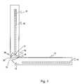
- FIG. 6shows a front view of the mobile station of FIG. 1 in a partially extended mode
- FIG. 6shows a front view of the mobile station in a partially extended mode.
- the battery housing element 12 and the electronics housing element 13are provided with a stop mechanism.
- the stop mechanismuses a stud 62 provided on the upper storing element 11 .
- the flange 72has the first abutment surface 73 that is its leading edge. This surface prevents further opening of the mobile station beyond a certain opening angle.
- the recess 74has an inner wall (the second direct wall of the sector) defining the second abutment surface 77 , which defines the first opening angle. This first opening angle defines the maximum opening angle when the mobile station is being used as a telephone.
- the stop 76provides a third abutment surface which faces roughly towards the hinged end of the electronics housing element.
Landscapes
- Engineering & Computer Science (AREA)
- Theoretical Computer Science (AREA)
- Computer Hardware Design (AREA)
- Physics & Mathematics (AREA)
- General Physics & Mathematics (AREA)
- General Engineering & Computer Science (AREA)
- Human Computer Interaction (AREA)
- Signal Processing (AREA)
- Mathematical Physics (AREA)
- Telephone Set Structure (AREA)
- Optical Communication System (AREA)
- Two-Way Televisions, Distribution Of Moving Picture Or The Like (AREA)
- Gyroscopes (AREA)
- Input From Keyboards Or The Like (AREA)
Abstract
Description
- a flexible input means for receiving user input; and
- a housing defining a space for accommodating said input means; characterised in that
- said input device has a first state and a second state; wherein
- the input means adopts a compacted spatial configuration in the first state and adopts an extended spatial configuration in the second state.
- a flexible output means for outputting information; and
- a housing defining a space for accommodating said output means; characterised in that
- said input device has a first state and a second state; wherein
- the output means adopts a compacted spatial configuration in the first state and adopts an extended spatial configuration in the second state.
- two elements, which are foldable about a hinge between an open configuration and a closed configuration,
- a speaker located in one element, and
- a microphone in another element.
- a stop to prevent the device being opened beyond a certain maximum opening angle, and
- a means for changing the maximum opening angle when the configuration of the device is changed between the compacted spatial configuration and the extended spatial configuration. This provides different maximum opening angles for when the device is to be used in a telephone mode and when it is to be used in a data terminal mode. For example, it is possible to reduce the opening of the device to a convenient viewing angle for the data terminal mode. In the telephone mode, the mobile station can be further opened to increase the distance of the microphone and the speaker from each other.
Claims (14)
Priority Applications (1)
| Application Number | Priority Date | Filing Date | Title |
|---|---|---|---|
| US11/055,774US7253802B2 (en) | 1999-12-08 | 2005-02-10 | User interface |
Applications Claiming Priority (4)
| Application Number | Priority Date | Filing Date | Title |
|---|---|---|---|
| FI19992636 | 1999-12-08 | ||
| FI992636AFI111998B (en) | 1999-12-08 | 1999-12-08 | User interface |
| US09/730,066US6873315B2 (en) | 1999-12-08 | 2000-12-05 | User interface |
| US11/055,774US7253802B2 (en) | 1999-12-08 | 2005-02-10 | User interface |
Related Parent Applications (1)
| Application Number | Title | Priority Date | Filing Date |
|---|---|---|---|
| US09/730,066ContinuationUS6873315B2 (en) | 1999-12-08 | 2000-12-05 | User interface |
Publications (2)
| Publication Number | Publication Date |
|---|---|
| US20050146498A1 US20050146498A1 (en) | 2005-07-07 |
| US7253802B2true US7253802B2 (en) | 2007-08-07 |
Family
ID=8555716
Family Applications (2)
| Application Number | Title | Priority Date | Filing Date |
|---|---|---|---|
| US09/730,066Expired - Fee RelatedUS6873315B2 (en) | 1999-12-08 | 2000-12-05 | User interface |
| US11/055,774Expired - LifetimeUS7253802B2 (en) | 1999-12-08 | 2005-02-10 | User interface |
Family Applications Before (1)
| Application Number | Title | Priority Date | Filing Date |
|---|---|---|---|
| US09/730,066Expired - Fee RelatedUS6873315B2 (en) | 1999-12-08 | 2000-12-05 | User interface |
Country Status (8)
| Country | Link |
|---|---|
| US (2) | US6873315B2 (en) |
| EP (1) | EP1238325B1 (en) |
| CN (1) | CN1322389C (en) |
| AT (1) | ATE243332T1 (en) |
| AU (1) | AU1527201A (en) |
| DE (1) | DE60003463T2 (en) |
| FI (1) | FI111998B (en) |
| WO (1) | WO2001042891A1 (en) |
Cited By (1)
| Publication number | Priority date | Publication date | Assignee | Title |
|---|---|---|---|---|
| US11029733B2 (en)* | 2019-05-03 | 2021-06-08 | Samsung Display Co., Ltd. | Display device |
Families Citing this family (69)
| Publication number | Priority date | Publication date | Assignee | Title |
|---|---|---|---|---|
| US6131047A (en) | 1997-12-30 | 2000-10-10 | Ericsson Inc. | Radiotelephones having contact-sensitive user interfaces and methods of operating same |
| US6739774B1 (en)* | 2000-02-01 | 2004-05-25 | Rast Associates, Llc | Expandable and contractible keyboard with adjustable key sizes |
| WO2001056803A1 (en) | 2000-02-01 | 2001-08-09 | R.A.S.T. Associates | Expandable and contractible keyboard with adjustable key sizes |
| GB2370657A (en)* | 2000-12-28 | 2002-07-03 | Constantinos Hadjisotiriou | Foldable flexible computer |
| EP1251673A1 (en)* | 2001-04-20 | 2002-10-23 | E-Trade Int'l Group Limited | Consumerelectronics device and actuation arrangement therefor |
| US6554619B2 (en)* | 2001-04-25 | 2003-04-29 | Jacquelyn Williams | Electronic instructional device for point-of-performance instruction |
| US20030048256A1 (en)* | 2001-09-07 | 2003-03-13 | Salmon Peter C. | Computing device with roll up components |
| DE20118593U1 (en)* | 2001-11-16 | 2002-05-23 | Jahn Hartmut | Multifunctional communication device |
| AU2002360497A1 (en) | 2001-12-06 | 2003-06-23 | Rast Associates, Llc | Expandable and contractible keyboard device |
| US7050835B2 (en)* | 2001-12-12 | 2006-05-23 | Universal Display Corporation | Intelligent multi-media display communication system |
| JP4563031B2 (en)* | 2001-12-12 | 2010-10-13 | ユニバーサル ディスプレイ コーポレイション | Multimedia display communication system with information processing function |
| DE60310874T2 (en)* | 2003-03-25 | 2007-09-06 | Sony Ericsson Mobile Communications Ab | Extractable terminal keypad |
| WO2004086203A2 (en)* | 2003-03-25 | 2004-10-07 | Sony Ericsson Mobile Communications Ab | Extractable terminal keypad |
| US7786951B2 (en) | 2003-04-01 | 2010-08-31 | Polymer Vision Limited | Apparatus with display |
| EP1480417B1 (en)* | 2003-05-21 | 2006-07-19 | Sony Ericsson Mobile Communications AB | Clamshell-type mobile terminal with flexible display |
| EP1642253B1 (en) | 2003-06-23 | 2012-10-03 | Simon Richard Daniel | Display device having an extendible screen |
| US7173781B2 (en)* | 2003-06-26 | 2007-02-06 | Seagate Technology Llc | Multi-tracks MR offset tuning based on error count in certification process |
| FI20040853L (en) | 2004-06-18 | 2005-12-19 | Nokia Corp | Opening and closing a user interface element |
| US7667962B2 (en) | 2004-08-20 | 2010-02-23 | Mullen Jeffrey D | Wireless devices with flexible monitors and keyboards |
| US20060068722A1 (en)* | 2004-09-28 | 2006-03-30 | Ashman William C Jr | Wireless communications device with extendable and retractable input/output device |
| ATE539429T1 (en)* | 2004-10-05 | 2012-01-15 | Creator Technology Bv | ROLL-UP DISPLAY DEVICE |
| CN100565622C (en)* | 2004-10-05 | 2009-12-02 | 皇家飞利浦电子股份有限公司 | scrollable display device |
| TWI259715B (en)* | 2005-01-25 | 2006-08-01 | Wistron Corp | Electronic device able to adjust the size of the display area |
| JP4386940B2 (en)* | 2005-03-18 | 2009-12-16 | 富士通株式会社 | Remote control device |
| US7724508B2 (en)* | 2005-05-20 | 2010-05-25 | Polymer Vision Limited | Protective cover for flexible display screen |
| CN101288038B (en) | 2005-05-23 | 2012-07-04 | 创造者科技有限公司 | Partially flexible displays device |
| US7558057B1 (en) | 2005-06-06 | 2009-07-07 | Alex Naksen | Personal digital device with adjustable interface |
| WO2007000719A1 (en)* | 2005-06-29 | 2007-01-04 | Polymer Vision Limited | Foldable electronic display devices having flexible and / or rollable screens |
| US8406866B2 (en)* | 2005-12-06 | 2013-03-26 | St. Jude Medical, Atrial Fibrillation Division, Inc. | System and method for assessing coupling between an electrode and tissue |
| EP1960828A2 (en)* | 2005-12-16 | 2008-08-27 | Polymer Vision Limited | Circular displays |
| WO2007072234A1 (en)* | 2005-12-20 | 2007-06-28 | Polymer Vision Limited | Display device having an extendable flexible screen rollable around a batter |
| US7532460B2 (en)* | 2005-12-29 | 2009-05-12 | Sap Ag | Portable computer system |
| US8068605B2 (en)* | 2006-03-07 | 2011-11-29 | Sony Ericsson Mobile Communications Ab | Programmable keypad |
| JP5108293B2 (en)* | 2006-12-20 | 2012-12-26 | 富士フイルム株式会社 | Portable device and imaging device |
| TWI413037B (en)* | 2007-06-15 | 2013-10-21 | Creator Technology Bv | Electronic device with a variable angulation of a flexible display |
| CN101872254A (en)* | 2009-04-24 | 2010-10-27 | 鸿富锦精密工业(深圳)有限公司 | Portable handwriting input device |
| US8591128B2 (en)* | 2009-07-01 | 2013-11-26 | Nokia Corporation | Extendable mechanism |
| US8111505B2 (en)* | 2009-10-16 | 2012-02-07 | Apple Inc. | Computer housing |
| US8379377B2 (en) | 2010-01-20 | 2013-02-19 | Creator Technology B.V. | Electronic device with at least one extendable display section |
| KR101067587B1 (en)* | 2010-01-29 | 2011-09-27 | 주식회사 팬택 | Flexible terminal with shape conversion characteristics, shape conversion method and shape conversion device |
| KR101227644B1 (en)* | 2010-08-10 | 2013-01-30 | 유상규 | Rollable flexible display device |
| US20120086630A1 (en) | 2010-10-12 | 2012-04-12 | Sony Computer Entertainment Inc. | Using a portable gaming device to record or modify a game or application in real-time running on a home gaming system |
| US9286812B2 (en) | 2011-06-07 | 2016-03-15 | Microsoft Technology Licensing, Llc | Flexible display extendable assembly |
| US20130002114A1 (en)* | 2011-06-29 | 2013-01-03 | Polymer Vision B.V. | Flexible Display With Cover Positioning Means |
| US8711566B2 (en) | 2011-09-02 | 2014-04-29 | Microsoft Corporation | Expandable mobile device |
| US8929085B2 (en)* | 2011-09-30 | 2015-01-06 | Apple Inc. | Flexible electronic devices |
| KR102148717B1 (en) | 2011-12-05 | 2020-08-28 | 삼성전자주식회사 | Method for controlling display in a portable terminal and apparatus thereof |
| WO2013083945A2 (en)* | 2011-12-05 | 2013-06-13 | Massimiliano Scarano | Smartphone with oled that turns into tablet |
| JP5783039B2 (en)* | 2011-12-28 | 2015-09-24 | 富士通株式会社 | Multi-divided housing coupling device and electronic device including the coupling device |
| DE102012101210A1 (en) | 2012-02-15 | 2013-08-22 | Maxim Stührenberg | Display device e.g. contact-sensitive display device, for use in mobile telephone for displaying images, has holding unit holding displaying unit in utilized condition and temporary extendably arranged on housing in discharging direction |
| FI20120340A7 (en)* | 2012-10-08 | 2014-04-09 | Canatu Oy | A touch interface device and design |
| JP5979313B2 (en)* | 2013-04-30 | 2016-08-24 | 富士通株式会社 | Multi-divided housing coupling device and electronic device including the coupling device |
| KR102072686B1 (en)* | 2013-06-05 | 2020-02-03 | 엘지전자 주식회사 | Image display device |
| KR102066716B1 (en) | 2013-06-20 | 2020-01-15 | 삼성전자주식회사 | Method of operating and electronic device thereof |
| CN104424844B (en)* | 2013-08-26 | 2017-04-19 | 联想(北京)有限公司 | Flexible display device and electronic product |
| CN104656774B (en)* | 2013-11-20 | 2020-02-21 | 联想(北京)有限公司 | Electronic equipment |
| WO2016045121A1 (en)* | 2014-09-28 | 2016-03-31 | Hewlett-Packard Development Company,L.P. | Electronic touch buttons |
| WO2016101123A1 (en)* | 2014-12-23 | 2016-06-30 | 深圳市柔宇科技有限公司 | Flexible screen extension structure, flexible screen assembly, and terminal |
| KR102277260B1 (en)* | 2014-12-29 | 2021-07-14 | 엘지전자 주식회사 | Terminal device and controlling method thereof |
| KR102301500B1 (en)* | 2015-01-22 | 2021-09-13 | 삼성디스플레이 주식회사 | Display device |
| US9625948B2 (en)* | 2015-08-24 | 2017-04-18 | Apple Inc. | Electronic devices with retractable displays |
| KR102492731B1 (en)* | 2016-06-09 | 2023-01-27 | 삼성디스플레이 주식회사 | Rollable display device |
| KR102534580B1 (en)* | 2016-07-27 | 2023-05-19 | 삼성디스플레이 주식회사 | Display device |
| US20190235579A1 (en)* | 2016-09-29 | 2019-08-01 | Shenzhen Royole Technologies Co., Ltd. | Electronic device |
| JP2020504331A (en)* | 2016-12-30 | 2020-02-06 | シェンジェン ロイオル テクノロジーズ カンパニー リミテッドShenzhen Royole Technologies Co., Ltd. | Support assembly and display device |
| CN108874031B (en)* | 2018-05-23 | 2021-08-17 | 上海创功通讯技术有限公司 | Screen switching method and device and terminal |
| TWI675235B (en) | 2018-10-11 | 2019-10-21 | 友達光電股份有限公司 | Display apparatus |
| EP4191373A4 (en) | 2020-11-12 | 2024-02-07 | Samsung Electronics Co., Ltd. | Electronic apparatus comprising roller |
| CN113472925B (en)* | 2021-06-29 | 2023-09-05 | Oppo广东移动通信有限公司 | Locking devices and electronics |
Citations (40)
| Publication number | Priority date | Publication date | Assignee | Title |
|---|---|---|---|---|
| US4145584A (en)* | 1976-04-28 | 1979-03-20 | Otterlei Jon L | Flexible keyboard switch with integral spacer protrusions |
| US4906843A (en)* | 1987-12-31 | 1990-03-06 | Marq Technolgies | Combination mouse, optical scanner and digitizer puck |
| US5220521A (en) | 1992-01-02 | 1993-06-15 | Cordata Incorporated | Flexible keyboard for computers |
| US5278779A (en)* | 1992-06-26 | 1994-01-11 | Conway Kevin M | Laptop computer with hinged keyboard |
| JPH06164440A (en)* | 1992-11-16 | 1994-06-10 | Hitachi Ltd | Portable information communication equipment |
| US5341154A (en)* | 1991-12-27 | 1994-08-23 | Bird Gregory F | Portable personal computer |
| US5517683A (en)* | 1995-01-18 | 1996-05-14 | Cycomm Corporation | Conformant compact portable cellular phone case system and connector |
| US5616897A (en) | 1993-06-30 | 1997-04-01 | Weber; Michael R. | Flexible keyboard |
| US5644338A (en) | 1993-05-26 | 1997-07-01 | Bowen; James H. | Ergonomic laptop computer and ergonomic keyboard |
| US5687058A (en)* | 1995-10-11 | 1997-11-11 | Mallinckrodt & Mallinckrodt | Method and apparatus for reducing at least one dimension of a computer keyboard for transportation and storage |
| US5703578A (en)* | 1997-01-16 | 1997-12-30 | International Business Machines Corporation | Folding keyboard |
| US5706167A (en)* | 1995-10-06 | 1998-01-06 | Samsung Electronics Co., Ltd. | Portable computer with separable keyboard which moves in response to movement of a display unit |
| EP0860969A2 (en) | 1997-02-21 | 1998-08-26 | Nokia Mobile Phones Ltd. | Mobile communication devices |
| US5898161A (en)* | 1994-08-29 | 1999-04-27 | Symbol Technologies, Inc. | Wrist-mounted optical scanning and pointing systems |
| JPH11272205A (en)* | 1998-03-19 | 1999-10-08 | Toshiba Corp | Display device |
| US5995025A (en)* | 1997-12-18 | 1999-11-30 | Daniel I. Sternglass | Folding keyboard with sliding segments for electronic products |
| US6028591A (en)* | 1986-08-27 | 2000-02-22 | Texas Instruments Incorporated | Keyboard with flexible display and prompt capability |
| US6046730A (en)* | 1996-03-15 | 2000-04-04 | At&T Corp | Backlighting scheme for a multimedia terminal keypad |
| US6047196A (en) | 1995-11-24 | 2000-04-04 | Nokia Mobile Phones, Ltd. | Communication device with two modes of operation |
| US6073034A (en)* | 1996-10-31 | 2000-06-06 | Kopin Corporation | Wireless telephone display system |
| US6073027A (en)* | 1996-08-29 | 2000-06-06 | Bellsouth Corporation | Portable radiotelephone with sliding cover and automatic antenna extension |
| US6075510A (en)* | 1997-10-28 | 2000-06-13 | Nortel Networks Corporation | Low power refreshing (smart display multiplexing) |
| US6108197A (en)* | 1992-05-15 | 2000-08-22 | Via, Inc. | Flexible wearable computer |
| WO2000054479A2 (en) | 1999-03-10 | 2000-09-14 | Renfer Robert O | Mobile telephone with a roll-out keyboard |
| US6249672B1 (en) | 1999-03-19 | 2001-06-19 | Mobile Communications Holdings, Inc. | Portable telephone |
| US6259409B1 (en)* | 1999-07-22 | 2001-07-10 | 3Com Corporation | Retractable sliding antenna assembly for wireless communication |
| US6307751B1 (en)* | 1998-06-01 | 2001-10-23 | Wearlogic, Inc. | Flexible circuit assembly |
| US6332084B1 (en)* | 1999-10-09 | 2001-12-18 | Qualcomm Incorporated | Multiple mode wireless telephone |
| US6390373B1 (en)* | 1995-12-11 | 2002-05-21 | Wolfgang Beyer | Chip card |
| US6397078B1 (en)* | 1999-08-27 | 2002-05-28 | Young S. Kim | Combined mobile telephone and personal digital assistant |
| US6434371B1 (en) | 1999-05-06 | 2002-08-13 | Qualcomm, Incorporated | Selecting flip phone operating mode using flip position |
| US20030071259A1 (en)* | 2001-10-15 | 2003-04-17 | Fujitsu Limited | Electrically conductive organic compound and electronic device |
| US6587675B1 (en)* | 1996-10-28 | 2003-07-01 | Therefore Limited | Hand-held computer and communications apparatus |
| US6594142B2 (en) | 2000-07-19 | 2003-07-15 | Pocketop Computers Corp. | Folding keyboard for a personal digital assistant |
| US6774888B1 (en)* | 2000-06-19 | 2004-08-10 | International Business Machines Corporation | Personal digital assistant including a keyboard which also acts as a cover |
| US6774819B1 (en) | 1999-07-23 | 2004-08-10 | Intel Corporation | Flexible keyboard |
| US20040227726A1 (en)* | 1998-06-23 | 2004-11-18 | Shahoian Erik J. | Haptic interface device and actuator assembly providing linear haptic sensations |
| US6894211B2 (en)* | 2001-09-21 | 2005-05-17 | Yamaha Corporation | Keyboard apparatus |
| US6943776B2 (en)* | 2000-07-24 | 2005-09-13 | Herman Ehrenburg | Computer-compatible, visualizably presented, intuitive and self-explanatory manual input system |
| US20060066590A1 (en)* | 2004-09-29 | 2006-03-30 | Masanori Ozawa | Input device |
Family Cites Families (3)
| Publication number | Priority date | Publication date | Assignee | Title |
|---|---|---|---|---|
| JP2776658B2 (en)* | 1991-10-15 | 1998-07-16 | 日本電気株式会社 | keyboard |
| US6067704A (en)* | 1997-06-12 | 2000-05-30 | Livernois Research And Development Company | Apparatus for assembling heat exchanger cores |
| JP2000132122A (en)* | 1998-10-28 | 2000-05-12 | Fuji Photo Film Co Ltd | Scroll-type display capable of continuous display |
- 1999
- 1999-12-08FIFI992636Apatent/FI111998B/ennot_activeIP Right Cessation
- 2000
- 2000-11-14EPEP00977624Apatent/EP1238325B1/ennot_activeExpired - Lifetime
- 2000-11-14ATAT00977624Tpatent/ATE243332T1/ennot_activeIP Right Cessation
- 2000-11-14DEDE60003463Tpatent/DE60003463T2/ennot_activeExpired - Lifetime
- 2000-11-14CNCNB008169039Apatent/CN1322389C/ennot_activeExpired - Fee Related
- 2000-11-14WOPCT/FI2000/000995patent/WO2001042891A1/enactiveIP Right Grant
- 2000-11-14AUAU15272/01Apatent/AU1527201A/ennot_activeAbandoned
- 2000-12-05USUS09/730,066patent/US6873315B2/ennot_activeExpired - Fee Related
- 2005
- 2005-02-10USUS11/055,774patent/US7253802B2/ennot_activeExpired - Lifetime
Patent Citations (42)
| Publication number | Priority date | Publication date | Assignee | Title |
|---|---|---|---|---|
| US4145584A (en)* | 1976-04-28 | 1979-03-20 | Otterlei Jon L | Flexible keyboard switch with integral spacer protrusions |
| US6028591A (en)* | 1986-08-27 | 2000-02-22 | Texas Instruments Incorporated | Keyboard with flexible display and prompt capability |
| US4906843A (en)* | 1987-12-31 | 1990-03-06 | Marq Technolgies | Combination mouse, optical scanner and digitizer puck |
| US5341154A (en)* | 1991-12-27 | 1994-08-23 | Bird Gregory F | Portable personal computer |
| US5220521A (en) | 1992-01-02 | 1993-06-15 | Cordata Incorporated | Flexible keyboard for computers |
| US6108197A (en)* | 1992-05-15 | 2000-08-22 | Via, Inc. | Flexible wearable computer |
| US5278779A (en)* | 1992-06-26 | 1994-01-11 | Conway Kevin M | Laptop computer with hinged keyboard |
| JPH06164440A (en)* | 1992-11-16 | 1994-06-10 | Hitachi Ltd | Portable information communication equipment |
| US5644338A (en) | 1993-05-26 | 1997-07-01 | Bowen; James H. | Ergonomic laptop computer and ergonomic keyboard |
| US5616897A (en) | 1993-06-30 | 1997-04-01 | Weber; Michael R. | Flexible keyboard |
| US5898161A (en)* | 1994-08-29 | 1999-04-27 | Symbol Technologies, Inc. | Wrist-mounted optical scanning and pointing systems |
| US5711013A (en)* | 1995-01-18 | 1998-01-20 | Cycomm Corporation | Conformant compact portable cellular phone case system and connector |
| US5517683A (en)* | 1995-01-18 | 1996-05-14 | Cycomm Corporation | Conformant compact portable cellular phone case system and connector |
| US5706167A (en)* | 1995-10-06 | 1998-01-06 | Samsung Electronics Co., Ltd. | Portable computer with separable keyboard which moves in response to movement of a display unit |
| US5687058A (en)* | 1995-10-11 | 1997-11-11 | Mallinckrodt & Mallinckrodt | Method and apparatus for reducing at least one dimension of a computer keyboard for transportation and storage |
| US6047196A (en) | 1995-11-24 | 2000-04-04 | Nokia Mobile Phones, Ltd. | Communication device with two modes of operation |
| US6390373B1 (en)* | 1995-12-11 | 2002-05-21 | Wolfgang Beyer | Chip card |
| US6046730A (en)* | 1996-03-15 | 2000-04-04 | At&T Corp | Backlighting scheme for a multimedia terminal keypad |
| US6073027A (en)* | 1996-08-29 | 2000-06-06 | Bellsouth Corporation | Portable radiotelephone with sliding cover and automatic antenna extension |
| US6587675B1 (en)* | 1996-10-28 | 2003-07-01 | Therefore Limited | Hand-held computer and communications apparatus |
| US6073034A (en)* | 1996-10-31 | 2000-06-06 | Kopin Corporation | Wireless telephone display system |
| US5703578A (en)* | 1997-01-16 | 1997-12-30 | International Business Machines Corporation | Folding keyboard |
| EP0860969A2 (en) | 1997-02-21 | 1998-08-26 | Nokia Mobile Phones Ltd. | Mobile communication devices |
| US6075510A (en)* | 1997-10-28 | 2000-06-13 | Nortel Networks Corporation | Low power refreshing (smart display multiplexing) |
| US5995025A (en)* | 1997-12-18 | 1999-11-30 | Daniel I. Sternglass | Folding keyboard with sliding segments for electronic products |
| JPH11272205A (en)* | 1998-03-19 | 1999-10-08 | Toshiba Corp | Display device |
| US6307751B1 (en)* | 1998-06-01 | 2001-10-23 | Wearlogic, Inc. | Flexible circuit assembly |
| US20040227726A1 (en)* | 1998-06-23 | 2004-11-18 | Shahoian Erik J. | Haptic interface device and actuator assembly providing linear haptic sensations |
| WO2000054479A2 (en) | 1999-03-10 | 2000-09-14 | Renfer Robert O | Mobile telephone with a roll-out keyboard |
| US6249672B1 (en) | 1999-03-19 | 2001-06-19 | Mobile Communications Holdings, Inc. | Portable telephone |
| US6434371B1 (en) | 1999-05-06 | 2002-08-13 | Qualcomm, Incorporated | Selecting flip phone operating mode using flip position |
| US6259409B1 (en)* | 1999-07-22 | 2001-07-10 | 3Com Corporation | Retractable sliding antenna assembly for wireless communication |
| US6774819B1 (en) | 1999-07-23 | 2004-08-10 | Intel Corporation | Flexible keyboard |
| US6397078B1 (en)* | 1999-08-27 | 2002-05-28 | Young S. Kim | Combined mobile telephone and personal digital assistant |
| US6332084B1 (en)* | 1999-10-09 | 2001-12-18 | Qualcomm Incorporated | Multiple mode wireless telephone |
| US6774888B1 (en)* | 2000-06-19 | 2004-08-10 | International Business Machines Corporation | Personal digital assistant including a keyboard which also acts as a cover |
| US6594142B2 (en) | 2000-07-19 | 2003-07-15 | Pocketop Computers Corp. | Folding keyboard for a personal digital assistant |
| US6943776B2 (en)* | 2000-07-24 | 2005-09-13 | Herman Ehrenburg | Computer-compatible, visualizably presented, intuitive and self-explanatory manual input system |
| US6894211B2 (en)* | 2001-09-21 | 2005-05-17 | Yamaha Corporation | Keyboard apparatus |
| US20030071259A1 (en)* | 2001-10-15 | 2003-04-17 | Fujitsu Limited | Electrically conductive organic compound and electronic device |
| US6936190B2 (en)* | 2001-10-15 | 2005-08-30 | Fujitsu Limited | Electrically conductive organic compound and electronic device |
| US20060066590A1 (en)* | 2004-09-29 | 2006-03-30 | Masanori Ozawa | Input device |
Non-Patent Citations (8)
| Title |
|---|
| EMFi KEYPADS article. |
| Japanese Patent Abstract No. JP 06164440. |
| Japanese Patent Application No. JP 10319879 with English Translation of the Abstract. |
| Japanese Patent Application No. JP 11109880 with English Translation of the Abstract. |
| Japanese Patent Application No. JP 11272205 with English Translation of the Abstract. |
| Japanese Patent Application No. JP 4178684 with English Translation of the Abstract. |
| Patent Abstracts of Japan Publication No. JP 2000132122 A. |
| Patent Abstracts of Japan Publication No. JP 5-109342. |
Cited By (1)
| Publication number | Priority date | Publication date | Assignee | Title |
|---|---|---|---|---|
| US11029733B2 (en)* | 2019-05-03 | 2021-06-08 | Samsung Display Co., Ltd. | Display device |
Also Published As
| Publication number | Publication date |
|---|---|
| WO2001042891A1 (en) | 2001-06-14 |
| ATE243332T1 (en) | 2003-07-15 |
| DE60003463D1 (en) | 2003-07-24 |
| FI19992636L (en) | 2001-06-09 |
| US20010003450A1 (en) | 2001-06-14 |
| CN1678970A (en) | 2005-10-05 |
| US20050146498A1 (en) | 2005-07-07 |
| FI111998B (en) | 2003-10-15 |
| EP1238325A1 (en) | 2002-09-11 |
| DE60003463T2 (en) | 2004-05-06 |
| CN1322389C (en) | 2007-06-20 |
| EP1238325B1 (en) | 2003-06-18 |
| US6873315B2 (en) | 2005-03-29 |
| AU1527201A (en) | 2001-06-18 |
Similar Documents
| Publication | Publication Date | Title |
|---|---|---|
| US7253802B2 (en) | User interface | |
| US11416031B2 (en) | Mobile device with an expandable screen | |
| US7622685B2 (en) | Portable information terminal | |
| CN101388918B (en) | Electronic equipment | |
| CN107077168B (en) | Mobile computing device with flexible hinge structure | |
| CN102469183B (en) | Dual display folder type terminal | |
| CN105518567B (en) | Portable terminal | |
| KR100867608B1 (en) | Foldable handheld terminal | |
| US20150378395A1 (en) | Folding multimedia display device | |
| JP2004536475A (en) | Portable electronic device with additional electro-optical display | |
| JPH1168896A (en) | Portable radio equipment | |
| US8369071B2 (en) | Portable terminal | |
| KR20040025624A (en) | Dual slide display | |
| CN114924619A (en) | Display terminal | |
| JPH11212665A (en) | Thin computer device | |
| JP2005141715A (en) | Portable terminal device | |
| JP3726052B2 (en) | Mobile terminal device | |
| CN115331555B (en) | display device | |
| CN222073195U (en) | Mobile phone with movable shaft inner roll type drawing folding screen | |
| JP2006109398A (en) | Mobile device | |
| JP5780575B2 (en) | Display device and information display device |
Legal Events
| Date | Code | Title | Description |
|---|---|---|---|
| AS | Assignment | Owner name:NOKIA MOBILE PHONES LTD., FINLAND Free format text:ASSIGNMENT OF ASSIGNORS INTEREST;ASSIGNORS:HEMIA, TEPPO;HIETAMAKI, JOUNI;MERILAHTI, MIIKKA;AND OTHERS;REEL/FRAME:016276/0602;SIGNING DATES FROM 20001018 TO 20041018 | |
| STCF | Information on status: patent grant | Free format text:PATENTED CASE | |
| FEPP | Fee payment procedure | Free format text:PAYOR NUMBER ASSIGNED (ORIGINAL EVENT CODE: ASPN); ENTITY STATUS OF PATENT OWNER: LARGE ENTITY | |
| FPAY | Fee payment | Year of fee payment:4 | |
| AS | Assignment | Owner name:NOKIA CORPORATION, FINLAND Free format text:MERGER;ASSIGNOR:NOKIA MOBILE PHONES LTD.;REEL/FRAME:026101/0560 Effective date:20080612 | |
| AS | Assignment | Owner name:NOKIA CORPORATION, FINLAND Free format text:SHORT FORM PATENT SECURITY AGREEMENT;ASSIGNOR:CORE WIRELESS LICENSING S.A.R.L.;REEL/FRAME:026894/0665 Effective date:20110901 Owner name:MICROSOFT CORPORATION, WASHINGTON Free format text:SHORT FORM PATENT SECURITY AGREEMENT;ASSIGNOR:CORE WIRELESS LICENSING S.A.R.L.;REEL/FRAME:026894/0665 Effective date:20110901 | |
| AS | Assignment | Owner name:2011 INTELLECTUAL PROPERTY ASSET TRUST, DELAWARE Free format text:CHANGE OF NAME;ASSIGNOR:NOKIA 2011 PATENT TRUST;REEL/FRAME:027121/0353 Effective date:20110901 Owner name:NOKIA 2011 PATENT TRUST, DELAWARE Free format text:ASSIGNMENT OF ASSIGNORS INTEREST;ASSIGNOR:NOKIA CORPORATION;REEL/FRAME:027120/0608 Effective date:20110531 | |
| AS | Assignment | Owner name:CORE WIRELESS LICENSING S.A.R.L., LUXEMBOURG Free format text:ASSIGNMENT OF ASSIGNORS INTEREST;ASSIGNOR:2011 INTELLECTUAL PROPERTY ASSET TRUST;REEL/FRAME:027414/0867 Effective date:20110831 | |
| FPAY | Fee payment | Year of fee payment:8 | |
| AS | Assignment | Owner name:MICROSOFT CORPORATION, WASHINGTON Free format text:UCC FINANCING STATEMENT AMENDMENT - DELETION OF SECURED PARTY;ASSIGNOR:NOKIA CORPORATION;REEL/FRAME:039872/0112 Effective date:20150327 | |
| AS | Assignment | Owner name:CONVERSANT WIRELESS LICENSING S.A R.L., LUXEMBOURG Free format text:CHANGE OF NAME;ASSIGNOR:CORE WIRELESS LICENSING S.A.R.L.;REEL/FRAME:043816/0430 Effective date:20170720 | |
| AS | Assignment | Owner name:CPPIB CREDIT INVESTMENTS, INC., CANADA Free format text:AMENDED AND RESTATED U.S. PATENT SECURITY AGREEMENT (FOR NON-U.S. GRANTORS);ASSIGNOR:CONVERSANT WIRELESS LICENSING S.A R.L.;REEL/FRAME:046897/0001 Effective date:20180731 | |
| MAFP | Maintenance fee payment | Free format text:PAYMENT OF MAINTENANCE FEE, 12TH YEAR, LARGE ENTITY (ORIGINAL EVENT CODE: M1553); ENTITY STATUS OF PATENT OWNER: LARGE ENTITY Year of fee payment:12 | |
| AS | Assignment | Owner name:CONVERSANT WIRELESS LICENSING S.A R.L., LUXEMBOURG Free format text:RELEASE BY SECURED PARTY;ASSIGNOR:CPPIB CREDIT INVESTMENTS INC.;REEL/FRAME:055546/0062 Effective date:20210302 | |
| AS | Assignment | Owner name:CONVERSANT WIRELESS LICENSING LTD., TEXAS Free format text:ASSIGNMENT OF ASSIGNORS INTEREST;ASSIGNOR:CONVERSANT WIRELESS LICENSING S.A R.L.;REEL/FRAME:063492/0197 Effective date:20221130 | |
| AS | Assignment | Owner name:CONVERSANT WIRELESS LICENSING LTD., TEXAS Free format text:ASSIGNMENT OF ASSIGNORS INTEREST;ASSIGNOR:CONVERSANT WIRELESS LICENSING S.A R.L.;REEL/FRAME:063947/0530 Effective date:20221130 |