US7253742B2 - Method and apparatus for measuring parameters of a fluid flowing within a pipe using a configurable array of sensors - Google Patents
Method and apparatus for measuring parameters of a fluid flowing within a pipe using a configurable array of sensorsDownload PDFInfo
- Publication number
- US7253742B2 US7253742B2US10/909,592US90959204AUS7253742B2US 7253742 B2US7253742 B2US 7253742B2US 90959204 AUS90959204 AUS 90959204AUS 7253742 B2US7253742 B2US 7253742B2
- Authority
- US
- United States
- Prior art keywords
- sensors
- flow
- pipe
- array
- pressure
- Prior art date
- Legal status (The legal status is an assumption and is not a legal conclusion. Google has not performed a legal analysis and makes no representation as to the accuracy of the status listed.)
- Expired - Lifetime, expires
Links
Images


Classifications
- G—PHYSICS
- G01—MEASURING; TESTING
- G01F—MEASURING VOLUME, VOLUME FLOW, MASS FLOW OR LIQUID LEVEL; METERING BY VOLUME
- G01F1/00—Measuring the volume flow or mass flow of fluid or fluent solid material wherein the fluid passes through a meter in a continuous flow
- G01F1/704—Measuring the volume flow or mass flow of fluid or fluent solid material wherein the fluid passes through a meter in a continuous flow using marked regions or existing inhomogeneities within the fluid stream, e.g. statistically occurring variations in a fluid parameter
- G01F1/708—Measuring the time taken to traverse a fixed distance
- G01F1/7082—Measuring the time taken to traverse a fixed distance using acoustic detecting arrangements
- G—PHYSICS
- G01—MEASURING; TESTING
- G01F—MEASURING VOLUME, VOLUME FLOW, MASS FLOW OR LIQUID LEVEL; METERING BY VOLUME
- G01F1/00—Measuring the volume flow or mass flow of fluid or fluent solid material wherein the fluid passes through a meter in a continuous flow
- G01F1/704—Measuring the volume flow or mass flow of fluid or fluent solid material wherein the fluid passes through a meter in a continuous flow using marked regions or existing inhomogeneities within the fluid stream, e.g. statistically occurring variations in a fluid parameter
- G01F1/708—Measuring the time taken to traverse a fixed distance
- G01F1/712—Measuring the time taken to traverse a fixed distance using auto-correlation or cross-correlation detection means
- G—PHYSICS
- G01—MEASURING; TESTING
- G01F—MEASURING VOLUME, VOLUME FLOW, MASS FLOW OR LIQUID LEVEL; METERING BY VOLUME
- G01F1/00—Measuring the volume flow or mass flow of fluid or fluent solid material wherein the fluid passes through a meter in a continuous flow
- G01F1/74—Devices for measuring flow of a fluid or flow of a fluent solid material in suspension in another fluid
Definitions
- This inventionrelates to an apparatus for measuring at least one parameter associated with a fluid flowing within a pipe, and more particularly to an apparatus including a configurable array of sensors for characterizing unsteady pressures in the fluid for use in determining at least one parameter associated with the fluid, such as volumetric flow rate, composition, velocity, mass flow rate, density and particle size of the fluid and health of a diagnosed component of the flow process.
- a fluid flow processincludes any process that involves the flow of fluid through pipes, ducts, or other conduits, as well as through fluid control devices such as pumps, valves, orifices, heat exchangers, and the like.
- Flow processesare found in many different industries such as the oil and gas industry, refining, food and beverage industry, chemical and petrochemical industry, pulp and paper industry, power generation, pharmaceutical industry, and water and wastewater treatment industry.
- the fluid within the flow processmay be a single phase fluid (e.g., gas, liquid or liquid/liquid mixture) and/or a multi-phase mixture (e.g. paper and pulp slurries or other solid/liquid mixtures).
- the multi-phase mixturemay be a two-phase liquid/gas mixture, a solid/gas mixture or a solid/liquid mixture, gas entrained liquid or a three-phase mixture.
- Such physical parametersinclude, for example, volumetric flow rate, composition, consistency, density, and mass flow rate.
- a method and apparatus for measuring a parameter of a fluid passing through a pipeincluding a spatial array of pressure sensors disposed at different axial locations along the pipe. Each of the pressure sensors provides a pressure signal indicative of unsteady pressure within the pipe at a corresponding axial location of the pipe.
- a signal processorreceives the pressure signals from each of the pressure sensors, and determines the parameter of the fluid using the pressure signals from selected ones of the pressure sensors.
- the parameter of the fluidmay include, for example, at least one of: density of the fluid, volumetric flow rate of the fluid, mass flow rate of the fluid, composition of the fluid, entrained air in the fluid, consistency of the fluid, size of particles in the fluid, and health of a device causing the unsteady pressures to be generated in the pipe.
- the signal processormay select the selected ones of the pressure sensors using various criteria. For example: the signal processor may select the selected ones of the pressure sensors based on the parameter of the fluid to be output by the signal processor; the selected ones of the pressure sensors may be predetermined for the parameter of the fluid; the selected ones of the pressure sensors may be selected in response to a previously determined parameter of the fluid; the selected ones of the pressure sensors may be selected in response to an input signal; the selected ones of the pressure sensors may be selected in response to indication of a faulty pressure sensor; and the selected ones of the pressure sensors may be selected in response to a condition associated with the pipe (e.g. vibration).
- a condition associated with the pipee.g. vibration
- an array of, spaced-apart pressure sensorsis formed on a single sheet of PVDF.
- Each of the pressure sensorscomprises: a first electrode disposed on a first side of the sheet of PVDF, and a second electrode disposed on a second side of the sheet of PVDF opposite the first electrode.
- Each of the first and second electrodesmay be formed as an elongated strip of conductive material.
- the first and second electrodesmay extend around at least a portion of the outer surface of the pipe and substantially parallel to adjacent first and second electrodes.
- the elongated strip of conductive materialmay be formed from silver ink applied to the sheet of PVDF, and the first and second electrodes may be disposed between layers of a non-conductive material.
- a connectormay be connected to each of the pressure sensors, with the connector being electrically coupled to the signal processor.
- each of the pressure sensorsfurther comprises: a plurality of electrically connected first electrodes disposed on the first side of the sheet of PVDF, and a plurality of electrically connected second electrodes disposed on the second side of the sheet of PVDF opposite the plurality of first electrodes.
- FIG. 1is schematic diagram of an apparatus for determining at least one parameter associated with a fluid flowing in a pipe, the apparatus including a configurable array of sensors for characterizing unsteady pressures in the fluid, in accordance with various embodiments of the present invention.
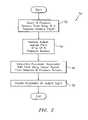
- FIG. 2is a block diagram of a method for determining at least one parameter associated with a fluid flowing in a pipe using a configurable array of sensors for characterizing the unsteady pressures in the fluid, in accordance with various embodiments of the present invention.
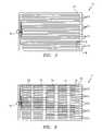
- FIG. 3is a plan view of a portion of the configurable array of sensors in accordance with various embodiments of the present invention.
- FIG. 4is a cross-sectional elevation view of the configurable array of sensors taken along section 4 - 4 of FIG. 3 .
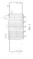
- FIG. 5is a plan view of the configurable array of sensors wrapped around an external surface of the pipe.
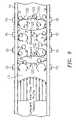
- FIG. 6is a plan view of an alternative configurable array of sensors in accordance with various embodiments of the present invention.
- FIG. 7is a block diagram of a diagnostic logic used in the apparatus of the present invention.
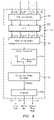
- FIG. 8is a block diagram of a first embodiment of a flow logic used in the apparatus of the present invention.
- FIG. 9is a cross-sectional view of a pipe having coherent structures therein.
- FIG. 10a k ⁇ plot of data processed from an apparatus embodying the present invention that illustrates slope of the convective ridge, and a plot of the optimization function of the convective ridge.
- FIG. 11is a block diagram of a second embodiment of a flow logic used in the apparatus of the present invention.
- FIG. 12a k ⁇ plot of data processed from an apparatus embodying the present invention that illustrates slope of the acoustic ridges.
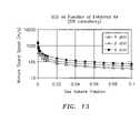
- FIG. 13is a plot of mixture sound speed as a function of gas volume fraction for a 5% consistency slurry over a range of process pressures.
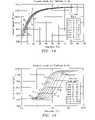
- FIG. 14is a plot of sound speed as a function of frequency for air/particle mixtures with fixed particle size and varying air-to-particle mass ratio.
- FIG. 15is a plot of sound speed as a function of frequency for air/particle mixtures with varying particle size where the air-to-particle mass ratio is fixed.
- the parameter of the fluidmay include, for example, at least one of: density of the fluid 13 , volumetric flow rate of the fluid 13 , mass flow rate of the fluid 13 , composition of the fluid 13 , entrained air in the fluid 13 , consistency of the fluid 13 , size of particles in the fluid 13 , and health of a device 34 causing the unsteady pressures to be generated in the pipe 14 .
- the apparatus 10includes a spatial array 11 of at least two pressure sensors 15 disposed at different axial locations x 1 . . . x N along the pipe 14 . Each of the pressure sensors 15 provides a pressure signal P(t) indicative of unsteady pressure within the pipe 14 at a corresponding axial location x 1 . . . x N of the pipe 14 .
- a signal processor 19receives the pressure signals P 1 (t) . . . P N (t) from the pressure sensors 15 in the array 11 , determines the parameter of the fluid 13 using pressure signals from selected ones of the pressure sensors 15 , and outputs the parameter as a signal 21 .
- the signal processor 19can effectively reconfigure the array 11 .
- the array 11 of pressure sensors 15may be formed on a single sheet of polyvinylidene fluoride (PVDF) that is wrapped around at least a portion of an outer surface of the pipe 14 . This arrangement allows a large number of pressure sensors 15 to be quickly and economically installed.
- PVDFpolyvinylidene fluoride
- the array 11 of pressure sensors 15includes two or more pressure sensors 15 , each providing a pressure signal P(t) indicative of unsteady pressure within the pipe 14 at a corresponding axial location X of the pipe 14 .
- the apparatusmay include 2, 3, 4, 5, 6, 7, 8, 9, 10, 11, 12, 13, 14, 15, 16, 17, 18, 19, 20, 21, 22, 23, or 24 pressure sensors 15 .
- the accuracy of the measurementimproves as the number of sensors in the array increases.
- the degree of accuracy provided by the greater number of sensorsis offset by the increase in complexity and time for computing the desired output parameter of the flow. Therefore, the number of sensors used is dependent at least on the degree of accuracy desired and the desired update rate of the output parameter provided by the apparatus 10 .
- the fluid 13may be a single or multiphase fluid flowing through a duct, conduit or other form of pipe 14 .
- the signals P 1 (t) . . . P N (t) provided by the pressure sensors 15 in the array 11are processed by the signal processor 19 , which may be part of a larger processing unit 20 .
- the signal processor 19may be a microprocessor and the processing unit 20 may be a personal computer or other general purpose computer. It is contemplated that the signal processor 19 may be any one or more signal processing devices for executing programmed instructions, such as one or more microprocessors or application specific integrated circuits (ASICS), and may include memory for storing programmed instructions, set points, parameters, and for buffering or otherwise storing data.
- ASICSapplication specific integrated circuits
- FIG. 2is a block diagram of a method 50 employed by processing unit 20 for determining the parameter 21 associated with the fluid 13 flowing in pipe 14 .
- the method 50begins at block 52 with the selection of a group of M pressure sensors 15 from the N pressure sensors 15 in the array 11 , where M is a number less than or equal to the number N.
- the signal processorreceives pressure signals P 1 (t) . . . P N (t) from each of the N pressure sensors 15 in the array 11 (block 54 ) and selectively processes the signals from the M selected pressure sensors 15 to determine the parameter associated with the fluid 13 (block 56 ).
- the signal processor 19then provides the parameter as an output signal 21 (block 58 ). While FIG.
- step 2depicts the step of selecting the group of M pressure sensors 15 (block 52 ) as occurring before the receipt of output signals P 1 (t) . . . P N (t) from the array 11 of N pressure sensors 15 (block 54 ), it is contemplated that the step of selecting (block 52 ) may follow the step of receiving (block 54 ).
- the signal processor 19may apply the data from the selected pressure sensors 15 to flow logic 36 executed by signal processor 19 .
- the one or more parameters 21may include such parameters as volumetric flow rate, mass flow rate, density, composition, entrained air, consistency, particle size, velocity, mach number, speed of sound propagating through the fluid 13 , and/or other parameters of the fluid 13 .
- the flow logic 36is described in further detail hereinafter.
- the signal processor 19may also apply one or more of the signals 15 and/or one or more parameters 21 from the flow logic 36 to diagnostic logic 38 .
- Diagnostic logic 38is executed by signal processor 19 to diagnose the health of any device 34 in the process flow that causes unsteady pressures to be generated in the pipe 14 .
- device 34is depicted as a valve; however, it is contemplated that device 34 may be any machinery, component, or equipment, e.g., motor, fan, pump, generator, engine, gearbox, belt, drive, pulley, hanger, clamp, actuator, valve, meter, or the like.
- the signal processor 19may output one or more parameters 21 indicative of the health of the diagnosed device 34 .
- the signal processormay also output a control signal 60 to control the device 34 in response to the parameter 21 .
- the diagnostic logic 38is described in further detail hereinafter.
- the signal processor 19may output the one or more parameters 21 to a display 24 or another input/output (I/O) device 26 .
- the I/O device 26also accepts user input parameters 48 as may be necessary for the flow logic 36 and diagnostic logic 38 .
- the I/O device 26 , display 24 , and signal processor 19 unitmay be mounted in a common housing, which may be attached to the array 11 by a flexible cable, wireless connection, or the like. The flexible cable may also be used to provide operating power from the processing unit 20 to the array 11 if necessary.
- the signal processor 19By selecting different pressure sensors 15 , the signal processor effectively reconfigures the array 11 . That is, by adjusting the number of input signals P (t) used to determine the parameter 21 , the signal processor 19 effectively adjusts the number of pressure sensors 15 in the array 11 .
- the signal processor 19may select three, four, eight, sixteen, twenty four, or N number of sensors pressure sensors 15 and apply the data from the selected pressure sensors to determine the parameter 21 .
- the accuracy of the measurementimproves as the number of sensors selected by the signal processor 19 increases.
- the degree of accuracy provided by the greater number of sensorsis offset by the increase in complexity and time for computing the desired output parameter of the flow. Therefore, the number of sensors selected is dependent at least on the degree of accuracy desired and the desire update rate of the output parameter provided by the apparatus 10 .
- the signal processor 19effectively adjusts the aperture (distance along the axis of pipe 14 ) between adjacent sensors 15 in the array 11 .
- the signal processor 19may select sensors at positions X 1 and X 2 for closer spacing, and sensors X 1 and X 4 for farther spacing.
- the signal processor 19may select sensors 15 to provide an array of evenly spaced sensors (e.g., sensors at positions X 1 , X 3 , X 5 , X 7 . . . ) or to provide an array of unevenly spaced sensors (e.g., sensors at positions X 1 , X 2 , X 4 , X 7 . . . ).
- the microprocessor 19may reconfigure the array 11 in response to any number of criteria.
- the signal processor 19may select one or more of the pressure sensors 15 in response to indication of a faulty pressure sensor 15 .
- the signal processor 19may compare the output signal of each pressure sensor 15 to a predetermined criteria (e.g., voltage level), and if the output signal indicates that a sensor 15 is faulty (e.g., if the output signal is outside the predetermined criteria) then the signal processor 19 may disregard output signals from the faulty pressure sensor 15 .
- a predetermined criteriae.g., voltage level
- the signal processor 19may also replace the faulty sensor 15 with another sensor 15 .
- the signal processor 19may select a different sensor 15 to replace the faulty sensor 15 in the array of eight sensors 15 .
- the signal processor 19selects the pressure sensors 15 based on the parameter 21 to be output by the signal processor 19 .
- the signal processor 19may use the output signals from one set M of pressure sensors 15 for determining one parameter 21 (e.g., flow rate) and a different set M of sensors 15 for determining another parameter 21 (e.g., speed of sound). This allows the number of pressure sensors 15 and the aperture (distance along the axis of pipe 14 ) between adjacent sensors 15 to be optimized for each different parameter 21 .
- the set M of sensors 15 for a given parameter 21may be predetermined, or the set M of sensors 15 for a given parameter 21 may be determined in response to a previously-determined parameter 21 of the fluid 13 .
- the number and/or aperture of the sensors 15 used to determine the flow ratemay be adjusted based on a previously determined velocity of the fluid 13 .
- the number and/or aperture of the sensors 15may be adjusted in attempt to obtain acceptable results.
- the adjustment in the number and/or aperture of the sensors 15can be performed by the signal processor 19 in real-time.
- the signal processor 19may select the selected ones of the pressure sensors 15 in response to a signal input via the I/O device 26 .
- the input signalmay indicate the parameter 21 to be determined by the signal processor 19 , in which case the signal processor 19 may select the pressure sensors 15 as described above.
- the input signalmay indicate the sensors 15 that are to be used by the signal processor 19 in determining a particular parameter 21 . This latter embodiment may be particularly useful by a technician in installing or troubleshooting the apparatus 10 or upgrading the apparatus 10 with new functionality.
- the signal processor 19may select the selected ones of the pressure sensors 15 to provide spatial filtering of conditions associated with the pipe 14 . For example, if it is desired for the sensors 15 to sense the strain in the pipe 14 due to pressure fluctuations but a large vibration in the pipe 14 exists, the vibration may mask the pressure fluctuation signal. By only utilizing sensors 15 which are in the nodes of the pipe 14 vibration, then the vibration based strains will be minimized and the pressure fluctuation strains can be measured.
- the pressure sensors 15may include electrical strain gages, optical fibers and/or gratings, ported sensors, ultrasonic sensors, among others as described herein, and may be attached to the pipe by adhesive, glue, epoxy, tape or other suitable attachment means to ensure suitable contact between the sensor and the pipe 14 .
- the sensors 15may alternatively be removable or permanently attached via known mechanical techniques such as mechanical fastener, spring loaded, clamped, clam shell arrangement, strapping or other equivalents.
- strain gages, including optical fibers and/or gratingsmay be embedded in a composite pipe 14 . If desired, for certain applications, gratings may be detached from (or strain or acoustically isolated from) the pipe 14 if desired.
- any other strain sensing techniquemay be used to measure the variations in strain in the pipe 14 , such as highly sensitive piezoelectric, electronic or electric, strain gages attached to or embedded in the pipe 14 .
- a piezo-electronic pressure transducermay be used as one or more of the pressure sensors and it may measure the unsteady (or dynamic or ac) pressure variations inside the pipe 14 by measuring the pressure levels inside of the pipe.
- the sensors 14comprise pressure sensors manufactured by PCB Piezotronics of Depew, N.Y.
- the sensors 14there are integrated circuit piezoelectric voltage mode-type sensors that feature built-in microelectronic amplifiers, and convert the high-impedance charge into a low-impedance voltage output.
- Model 106B manufactured by PCB Piezotronicswhich is a high sensitivity, acceleration compensated integrated circuit piezoelectric quartz pressure sensor suitable for measuring low pressure acoustic phenomena in hydraulic and pneumatic systems. It has the unique capability to measure small pressure changes of less than 0.001 psi under high static conditions.
- the 106Bhas a 300 mV/psi sensitivity and a resolution of 91 dB (0.0001 psi).
- the pressure sensors 15may incorporate a built-in MOSFET microelectronic amplifier to convert the high-impedance charge output into a low-impedance voltage signal.
- the sensors 15may be powered from a constant-current source and can operate over long coaxial or ribbon cable without signal degradation.
- the low-impedance voltage signalis not affected by triboelectric cable noise or insulation resistance-degrading contaminants. Power to operate integrated circuit piezoelectric sensors generally takes the form of a low-cost, 24 to 27 VDC, 2 to 20 mA constant-current supply.
- piezoelectric pressure sensorsare constructed with either compression mode quartz crystals preloaded in a rigid housing, or unconstrained tourmaline crystals. These designs give the sensors microsecond response times and resonant frequencies in the hundreds of kHz, with minimal overshoot or ringing. Small diaphragm diameters ensure spatial resolution of narrow shock waves.
- the output characteristic of piezoelectric pressure sensor systemsis that of an AC-coupled system, where repetitive signals decay until there is an equal area above and below the original base line. As magnitude levels of the monitored event fluctuate, the output remains stabilized around the base line with the positive and negative areas of the curve remaining equal.
- each of the pressure sensors 15may include a piezoelectric sensor that provides a piezoelectric material to measure the unsteady pressures of the fluid 13 .
- the piezoelectric materialsuch as the polymer, polarized fluoropolymer, PVDF, measures the strain induced within the process pipe 14 due to unsteady pressure variations within the fluid 13 . Strain within the pipe 14 is transduced to an output voltage or current by the attached piezoelectric sensors 15 .
- each piezoelectric sensor 15may be adhered to the outer surface of a steel strap that extends around and clamps onto the outer surface of the pipe 14 .
- the piezoelectric sensing elementis typically conformal to allow complete or nearly complete circumferential measurement of induced strain.
- the sensorscan be formed from PVDF films, co-polymer films, or flexible PZT sensors, similar to that described in “Piezo Film Sensors technical Manual” provided by Measurement Specialties, Inc. of Fairfield, N.J., which is incorporated herein by reference. The advantages of this technique are the following:
- the array 11 of pressure sensors 15is formed on a single sheet 62 of PVDF.
- FIG. 4shows a cross-sectional elevation view of a portion of the array 11 of pressure sensors 15 , as taken along section 4 - 4 of FIG. 3 .
- the sheet 62 of PVDFhas a plurality of pressure sensors 15 formed thereon, with each of the pressure sensors 15 being formed by a first electrode 64 disposed on a first side of the sheet 62 of PVDF, and a second electrode 66 disposed on a second side of the sheet 62 of PVDF opposite the first electrode 64 .
- each of the first and second electrodes 64 , 66is formed as an elongated strip of conductive material of substantially the same length, width, and thickness.
- the first and second electrodes 64 , 66 forming each pressure sensor 15are substantially parallel to the first and second electrodes 64 , 66 forming the adjacent pressure sensors 15 .
- the first and second electrodes 64 , 66 and the sheet 62 of PVDFmay be disposed between layers of a non-conductive material 68 , which acts to protect the PVDF sheet 62 and the electrodes 64 , 66 and prevents an electrical short between the electrodes and any external conductor.
- the first and second electrodes 64 , 66may be formed from any flexible, conductive material.
- Each elongated strip of conductive material forming the first and second electrodes 64 , 66may be formed from silver ink applied to the sheet 62 of PVDF.
- a variety of masking techniquescan be used to easily permit the deposition of the electrodes 64 66 only in specific areas.
- each elongated strip of conductive materialmay be formed by silk screening a silver ink coating on the sheet 62 .
- the electrode deposition processcan be used to route the various sensors 15 to a common location for easy attachment to a connector 70 ( FIG. 3 ) for connection to the signal processor 19 or processing unit 20 ( FIG. 1 ).
- each first and second electrode 64 , 66forms an “active” sensing area 72 .
- the sheet 62 of PVDFalso includes non-sensitive areas 74 separating adjacent active sensing areas 72 .
- the ability to form a plurality of sensors 15 on a single sheet 62 of PVDFis possible due to an interesting property of the PVDF material. That is, since the PVDF material is non-conductive, it will create only a local charge in response to a local strain (or temperature difference). Thus, when conductive electrodes 64 , 66 are placed covering an area of the PVDF material, it will become an integrating sensor only over the area covered by the electrodes 64 , 66 .
- the non-covered areai.e., the non-sensitive areas 74
- This behaviorpermits multiple independent sensors 15 to be created on a single sheet 62 of PVDF by only applying the electrodes 64 , 66 in specific areas.
- each sensor 15extends radially around at least a portion of the outer surface.
- Each sensor 15extends substantially fully around the outer surface of the pipe 14 , which allows each sensor 15 to sense the circumferential average of unsteady pressures at the corresponding axial location X and, therefore, reduce measurement errors associated with vibration or bending modes of the pipe 14 .
- PVDF sheet 62By forming multiple sensors 15 on a single PVDF sheet 62 , installation of the sensors 15 is accomplished by simply wrapping the sheet 15 around the pipe 14 .
- the PVDF sheet 62can be directly wrapped around the pipe 14 with an electrically insulative sheet between the sheet 62 and the pipe 14 .
- the PVDF sheet 62may be attached to the inner or outer surface of a sheet of material (e.g., a stainless steel sheet) which, in turn, is wrapped around and clamped onto the pipe 14 , similar to that described in U.S. Pat. No. 10/795,111, filed on Mar. 4, 2004, which is incorporated herein by reference. This reduces the time and effort previously associated with installing an array 11 of pressure sensors 15 on a pipe 14 .
- the sheet 62 of the present inventionthe installation and manufacturing costs are substantially the same regardless of the number of sensors 15 disposed on the sheet 62 .
- the sheet 62is particularly advantageous for the apparatus 10 having a configurable (selectable) array 11 of pressure sensors 15 .
- the configurability of the array 11is greatly increased.
- each of the pressure sensors 15includes a plurality of segments 76 , with each segment 76 being electrically connected to a single connector 70 on the end of the PVDF sheet 62 .
- Each segment 76is comprised of a plurality of electrically connected first electrodes 64 disposed on the first side of the sheet 62 of PVDF, and a plurality of electrically connected second electrodes 66 disposed on the second side of the sheet 62 of PVDF opposite the plurality of first electrodes 64 as shown in FIG. 4 .
- the diagnostic logic 38measures the sensor input signals (or evaluation input signals), which may include one or more of the signals P 1 (t), P 2 (t), P 3 (t), . . . P N (t) and the parameters 21 , at a step 80 .
- the diagnostic logic 38compares the evaluation input signals to a diagnostic evaluation criteria at a step 82 , discussed hereinafter. Then, a step 84 checks if there is a match, and if so, a step 86 provides a diagnostic signal indicative of the diagnostic condition that has been detected and may also provide information identifying the diagnosed device. The diagnostic signal may be output as a parameter 21 .
- the diagnostic evaluation criteriamay be based on a threshold value of the flow signal 24 .
- the threshold valuemay be indicative of a maximum or minimum sound speed, mach number, consistency, composition, entrained air, density, mass flow rate, volumetric flow rate, or the like. If there is not a criteria match in step 84 , the diagnostic logic 38 exits.
- the diagnostic evaluation criteriamay be a threshold (maximum or minimum) pressure.
- the diagnostic evaluation criteriamay be based on an acoustic signature, or a convective property (i.e., a property that propagates or convects with the flow).
- the diagnostic logic 38may monitor the acoustic signature of any upstream or downstream device (e.g., motor, fan, pump, generator, engine, gear box, belt drive, pulley, hanger, clamp, actuator, valve, meter, or other machinery, equipment or component).
- the data from the array 11may be processed in any domain, including the frequency/spatial domain, the temporal/spatial domain, the temporal/wave-number domain, or the wave-number/frequency (k- ⁇ ) domain or other domain, or any combination of one or more of the above.
- any known array processing technique in any of these or other related domainsmay be used if desired.
- kis the wave number
- ais the speed of sound of the material
- xis the location along the pipe
- ⁇is the Dirac delta function, which shows a spatial/temporal mapping of the acoustic field in the k- ⁇ plane.
- Any technique known in the art for using a spatial (or phased) array of sensors to determine the acoustic or convective fields, beam forming, or other signal processing techniques,may be used to provide an input evaluation signal to be compared to the diagnostic evaluation criteria.
- Each sensor 15provides a signal indicating an unsteady pressure at the location of each sensor 15 , at each instant in a series of sampling instants.
- the array 11may include more than two sensors 15 distributed at locations x 1 . . . x N .
- the pressure generated by the convective pressure disturbances(e.g., eddies 120 , see FIG. 9 ) may be measured through strained-based sensors 15 and/or pressure sensors 15 .
- the sensors 15provide analog pressure time-varying signals P 1 (t),P 2 (t),P 3 (t) . . . P N (t) to the signal processor 19 , which in turn applies selected ones of these signals P 1 (t),P 2 (t),P 3 (t), . . . P N (t) to the flow logic 36 .
- the flow logic 36processes the selected signals P 1 (t),P 2 (t),P 3 (t), . . . P N (t) to first provide output signals (parameters) 21 indicative of the pressure disturbances that convect with the fluid (process flow) 13 , and subsequently, provide output signals (parameters) 21 in response to pressure disturbances generated by convective waves propagating through the fluid 13 , such as velocity, Mach number and volumetric flow rate of the process flow 13 .
- the signal processor 19includes data acquisition unit 126 (e.g., A/D converter) that converts the analog signals P 1 (t) . . . P N (t) to respective digital signals and provides selected ones of the digital signals P 1 (t) . . . P N (t) to FFT logic 128 .
- the FFT logic 128calculates the Fourier transform of the digitized time-based input signals P 1 (t) . . . P N (t) and provides complex frequency domain (or frequency based) signals P 1 ( ⁇ ),P 2 ( ⁇ ),P 3 ( ⁇ ), . . . P N ( ⁇ ) indicative of the frequency content of the input signals.
- any other technique for obtaining the frequency domain characteristics of the signals P 1 (t)-P N (t),may be used.
- the cross-spectral density and the power spectral densitymay be used to form a frequency domain transfer functions (or frequency response or ratios) discussed hereinafter.
- One technique of determining the convection velocity of the turbulent eddies 120 within the process flow 13is by characterizing a convective ridge of the resulting unsteady pressures using an array of sensors or other beam forming techniques, similar to that described in U.S patent application, Ser. No. and U.S. patent application, Ser. No. 09/729,994, filed Dec. 4, 2000, now U.S. Pat. No. 6,609,069, which are incorporated herein by reference.
- a data accumulator 130accumulates the frequency signals P 1 ( ⁇ ) ⁇ P N ( ⁇ ) over a sampling interval, and provides the data to an array processor 132 , which performs a spatial-temporal (two-dimensional) transform of the sensor data, from the xt domain to the k- ⁇ domain, and then calculates the power in the k- ⁇ plane, as represented by a k- ⁇ plot.
- the array processor 132uses standard so-called beam forming, array processing, or adaptive array-processing algorithms, i.e. algorithms for processing the sensor signals using various delays and weighting to create suitable phase relationships between the signals provided by the different sensors, thereby creating phased antenna array functionality.
- the prior artteaches many algorithms of use in spatially and temporally decomposing a signal from a phased array of sensors, and the present invention is not restricted to any particular algorithm.
- One particular adaptive array processing algorithmis the Capon method/algorithm. While the Capon method is described as one method, the present invention contemplates the use of other adaptive array processing algorithms, such as MUSIC algorithm.
- the present inventionrecognizes that such techniques can be used to determine flow rate, i.e. that the signals caused by a stochastic parameter convecting with a flow are time stationary and have a coherence length long enough that it is practical to locate sensor units apart from each other and yet still be within the coherence length.
- kthe convection velocity (flow velocity).
- a plot of k- ⁇ pairsobtained from a spectral analysis of sensor samples associated with convective parameters portrayed so that the energy of the disturbance spectrally corresponding to pairings that might be described as a substantially straight ridge, a ridge that in turbulent boundary layer theory is called a convective ridge.
- What is being sensedare not discrete events of turbulent eddies, but rather a continuum of possibly overlapping events forming a temporally stationary, essentially white process over the frequency range of interest.
- the convective eddies 120is distributed over a range of length scales and hence temporal frequencies.
- the array processor 132determines the wavelength and so the (spatial) wavenumber k, and also the (temporal) frequency and so the angular frequency ⁇ , of various of the spectral components of the stochastic parameter.
- the array processor 132determines the wavelength and so the (spatial) wavenumber k, and also the (temporal) frequency and so the angular frequency ⁇ , of various of the spectral components of the stochastic parameter.
- the present inventionmay use temporal and spatial filtering to precondition the signals to effectively filter out the common mode characteristics P common mode and other long wavelength (compared to the sensor spacing) characteristics in the pipe 14 by differencing adjacent sensors 15 and retain a substantial portion of the stochastic parameter associated with the flow field and any other short wavelength (compared to the sensor spacing) low frequency stochastic parameters.
- the power in the k- ⁇ plane shown in a k- ⁇ plot of FIG. 10shows a convective ridge 124 .
- the convective ridgerepresents the concentration of a stochastic parameter that convects with the flow and is a mathematical manifestation of the relationship between the spatial variations and temporal variations described above. Such a plot will indicate a tendency for k- ⁇ pairs to appear more or less along a line 124 with some slope, the slope indicating the flow velocity.
- a convective ridge identifier 134uses one or another feature extraction method to determine the location and orientation (slope) of any convective ridge 124 present in the k- ⁇ plane.
- a so-called slant stacking methodis used, a method in which the accumulated frequency of k- ⁇ pairs in the k- ⁇ plot along different rays emanating from the origin are compared, each different ray being associated with a different trial convection velocity (in that the slope of a ray is assumed to be the flow velocity or correlated to the flow velocity in a known way).
- the convective ridge identifier 134provides information about the different trial convection velocities, information referred to generally as convective ridge information.
- Some or all of the functions within the flow logic 36may be implemented in software (using a microprocessor or computer) and/or firmware, or may be implemented using analog and/or digital hardware, having sufficient memory, interfaces, and capacity to perform the functions described herein.
- FIG. 11another example of flow logic 36 is shown. While the examples of FIG. 8 and FIG. 11 are shown separately, it is contemplated that the flow logic 36 may perform all of the functions described with reference to FIG. 8 and FIG. 11 .
- the array 11 of at least two sensors 15 located at two at least two locations x 1 ,x 2 axially along the pipe 14sense respective stochastic signals propagating between the sensors within the pipe at their respective locations.
- Each sensor 15provides a signal indicating an unsteady pressure at the location of each sensor 15 , at each instant in a series of sampling instants.
- the sensor array 11may include more than two pressure sensors 15 distributed at locations x 1 . . . x N .
- the pressure generated by the acoustic pressure disturbancesmay be measured through strained-based sensors and/or pressure sensors.
- the sensors 15provide analog pressure time-varying signals P 1 (t),P 2 (t),P 3 (t), . . . P N (t) to the flow logic 36 .
- the flow logic 36processes the signals P 1 (t),P 2 (t),P 3 (t), . . .
- P N (t)from selected ones of the sensors 15 to first provide output signals indicative of the speed of sound propagating through the fluid (process flow) 13 , and subsequently, provide output signals in response to pressure disturbances generated by acoustic waves propagating through the process flow 13 , such as velocity, Mach number and volumetric flow rate of the process flow 13 .
- the signal processor 19receives the pressure signals from the array 11 of sensors 15 .
- a data acquisition unit 138digitizes selected ones of the pressure signals P 1 (t) . . . P N (t) associated with the acoustic waves 122 propagating through the pipe 14 .
- an FFT logic 140calculates the Fourier transform of the selected digitized time-based input signals P 1 (t) . . . P N (t) and provides complex frequency domain (or frequency based) signals P 1 ( ⁇ ),P 2 ( ⁇ ),P 3 ( ⁇ ), . . . P N ( ⁇ ) indicative of the frequency content of the input signals.
- a data accumulator 142accumulates the frequency signals P 1 ( ⁇ ) . . . P N ( ⁇ ) over a sampling interval, and provides the data to an array processor 144 , which performs a spatial-temporal (two-dimensional) transform of the sensor data, from the xt domain to the k- ⁇ domain, and then calculates the power in the k- ⁇ plane, as represented by a k- ⁇ plot.
- the array processor 144determines the wavelength and so the (spatial) wavenumber k, and also the (temporal) frequency and so the angular frequency ⁇ , of various of the spectral components of the stochastic parameter.
- the array processor 144determines the wavelength and so the (spatial) wavenumber k, and also the (temporal) frequency and so the angular frequency ⁇ , of various of the spectral components of the stochastic parameter.
- the power in the k- ⁇ plane shown in a k- ⁇ plot of FIG. 12 so determinedwill exhibit a structure that is called an acoustic ridge 150 , 152 in both the left and right planes of the plot, wherein one of the acoustic ridges 150 is indicative of the speed of sound traveling in one axial direction and the other acoustic ridge 152 being indicative of the speed of sound traveling in the other axial direction.
- the acoustic ridgesrepresent the concentration of a stochastic parameter that propagates through the flow and is a mathematical manifestation of the relationship between the spatial variations and temporal variations described above. Such a plot will indicate a tendency for k- ⁇ pairs to appear more or less along a line 150 , 152 with some slope, the slope indicating the speed of sound.
- the power in the k- ⁇ plane so determinedis then provided to an acoustic ridge identifier 146 , which uses one or another feature extraction method to determine the location and orientation (slope) of any acoustic ridge present in the left and right k- ⁇ plane.
- the velocitymay be determined by using the slope of one of the two acoustic ridges 150 , 152 or averaging the slopes of the acoustic ridges 150 , 152 .
- information including the acoustic ridge orientation (slope)is used by an analyzer 148 to determine the flow parameters relating to measured speed of sound, such as the consistency or composition of the flow, the density of the flow, the average size of particles in the flow, the air/mass ratio of the flow, gas volume fraction of the flow, the speed of sound propagating through the flow, and/or the percentage of entrained air within the flow.
- the flow parameters relating to measured speed of soundsuch as the consistency or composition of the flow, the density of the flow, the average size of particles in the flow, the air/mass ratio of the flow, gas volume fraction of the flow, the speed of sound propagating through the flow, and/or the percentage of entrained air within the flow.
- the array processor 144uses standard so-called beam forming, array processing, or adaptive array-processing algorithms, i.e. algorithms for processing the sensor signals using various delays and weighting to create suitable phase relationships between the signals provided by the different sensors, thereby creating phased antenna array functionality.
- One such technique of determining the speed of sound propagating through the process flow 13is using array processing techniques to define an acoustic ridge in the k- ⁇ plane as shown in FIG. 12 .
- the slope of the acoustic ridgeis indicative of the speed of sound propagating through the process flow 13 .
- the speed of sound (SOS)is determined by applying sonar arraying processing techniques to determine the speed at which the one dimensional acoustic waves propagate past the axial array of unsteady pressure measurements distributed along the pipe 14 .
- the flow logic 36 of the present embodimentmeasures the speed of sound (SOS) of one-dimensional sound waves propagating through the process flow 13 to determine the gas volume fraction of the process flow 13 .
- SOSspeed of sound
- the speed of sound propagating through the pipe 14 and process flow 13may be determined using a number of known techniques, such as those set forth in U.S. patent application Ser. No. 09/344,094, filed Jun. 25, 1999, now U.S. Pat. No. 6,354,147; U.S. patent application Ser. No. 10/795,111, filed Mar. 4, 2004; U.S. patent application Ser. No. 09/997,221, filed Nov. 28, 2001, now U.S. Pat No.
- sonar-based flow meterusing an array of sensors 15 - 18 to measure the speed of sound of an acoustic wave propagating through the mixture is shown and described, one will appreciate that any means for measuring the speed of sound of the acoustic wave may used to determine the entrained gas volume fraction of the mixture/fluid or other characteristics of the flow described hereinbefore.
- the analyzer 148 of the flow logic 36provides output parameters 21 indicative of characteristics of the process flow 13 that are related to the measured speed of sound (SOS) propagating through the process flow 13 . For example, to determine the gas volume fraction (or phase fraction), the analyzer 148 assumes a nearly isothermal condition for the process flow 13 .
- SOSmeasured speed of sound
- the sound speed of a mixturecan be related to volumetric phase fraction ( ⁇ i ) of the components and the sound speed (a) and densities ( ⁇ ) of the component through the Wood equation.
- One dimensional compression waves propagating within a process flow 13 contained within a pipe 14exert an unsteady internal pressure loading on the pipe.
- the degree to which the pipe displaces as a result of the unsteady pressure loadinginfluences the speed of propagation of the compression wave.
- the relationship among the infinite domain speed of sound and density of a mixture; the elastic modulus (E), thickness (t), and radius (R) of a vacuum-backed cylindrical conduit; and the effective propagation velocity (a eff ) for one dimensional compressionis given by the following expression:
- the mixing ruleessentially states that the compressibility of a process flow (1/( ⁇ a 2 )) is the volumetrically-weighted average of the compressibilities of the components.
- a process flow 13consisting of a gas/liquid mixture at pressure and temperatures typical of paper and pulp industry
- the compressibility of gas phaseis orders of magnitudes greater than that of the liquid.
- the compressibility of the gas phase and the density of the liquid phaseprimarily determine mixture sound speed, and as such, it is necessary to have a good estimate of process pressure to interpret mixture sound speed in terms of volumetric fraction of entrained gas.
- the effect of process pressure on the relationship between sound speed and entrained air volume fractionis shown in FIG. 13 .
- the flow logic 36 of the present embodimentincludes the ability to accurately determine the average particle size of a particle/air or droplet/air mixture within the pipe 14 and the air to particle ratio.
- the propagation of one dimensional sound wave through multiphase mixturesis influenced by the effective mass and the effective compressibility of the mixture.
- the degree to which the no-slip assumption appliesis a strong function of particle size and frequency. In the limit of small particles and low frequency, the no-slip assumption is valid. As the size of the particles increases and the frequency of the sound waves increase, the non-slip assumption becomes increasing less valid.
- the increase in slip with frequencycauses dispersion, or, in other words, the sound speed of the mixture to change with frequency.
- dispersive characteristic of a process flow 13will provide a measurement of the average particle size, as well as, the air to particle ratio (particle/fluid ratio) of the process flow 13 .
- the dispersive nature of the systemutilizes a first principles model of the interaction between the air and particles.
- This modelis viewed as being representative of a class of models that seek to account for dispersive effects.
- Other modelscould be used to account for dispersive effects without altering the intent of this disclosure (for example, see the paper titled “Viscous Attenuation of Acoustic Waves in Suspensions” by R. L. Gibson, Jr. and M. N. Toksöz), which is incorporated herein by reference.
- the modelallows for slip between the local velocity of the continuous fluid phase and that of the particles.
- a mix ⁇ ( ⁇ )a f ⁇ 1 1 + ⁇ p ⁇ ⁇ p ⁇ f ⁇ ( 1 + ⁇ 2 ⁇ ⁇ p 2 ⁇ v p 2 K 2 )
- the fluid SOS, density ( ⁇ ) and viscosity ( ⁇ )are those of the pure phase fluid
- v pis the volume of individual particles
- ⁇ pis the volumetric phase fraction of the particles in the mixture.
- FIG. 14 and FIG. 15show the dispersive behavior in relations to the speed of sound for coal/air mixtures with parameters typical of those used in pulverized coal deliver systems.
- FIG. 14shows the predicted behavior for nominally 50 ⁇ m size coal in air for a range of air-to-fuel ratios.
- the effect of air-to-fuel ratiois well defined in the low frequency limit.
- the effect of the air-to-fuel ratiobecomes indistinguishable at higher frequencies, approaching the sound speed of the pure air at high frequencies (above ⁇ 100 Hz).
- FIG. 15shows the predicted behavior for a coal/air mixture with an air-to-fuel ratio of 1.8 with varying particle size. This figure illustrates that particle size has no influence on either the low frequency limit (quasi-steady ) sound speed, or on the high frequency limit of the sound speed. However, particle size does have a pronounced effect in the transition region.
- FIG. 14 and FIG. 15illustrate an important aspect of the present invention. Namely, that the dispersive properties of dilute mixtures of particles suspended in a continuous liquid can be broadly classified into three frequency regimes: low frequency range, high frequency range and a transitional frequency range. Although the effect of particle size and air-to-fuel ratio are inter-related, the predominant effect of air-to-fuel ratio is to determine the low frequency limit of the sound speed to be measured and the predominate effect of particle size is to determine the frequency range of the transitional regions. As particle size increases, the frequency at which the dispersive properties appear decreases. For typical pulverized coal applications, this transitional region begins at fairly low frequencies, ⁇ 2 Hz for 50 ⁇ m size particles.
- Some or all of the functions within the flow logic 36may be implemented in software (using a microprocessor or computer) and/or firmware, or may be implemented using analog and/or digital hardware, having sufficient memory, interfaces, and capacity to perform the functions described herein.
- FIG. 8 and FIG. 11depict two different embodiments of the flow logic 36 to measure various parameters of the flow process, the present invention contemplates that the functions of these two embodiments may be performed by a single flow logic 36 .
- the apparatus of the present inventionprovides a configurable array of sensors for use in determining at least one parameter associated with a fluid.
- a sheet of PVDF having a plurality of sensors disposed thereonBy using a sheet of PVDF having a plurality of sensors disposed thereon, a large number of sensors, and thus a highly configurable array, can be manufactured and installed both quickly and economically.
- system reliabilityis increased because redundant sensors can be created; if a fault is seen on one sensor, another can be activated to replace it.
- latent functionalitycan be created because, with the present invention, the array can be reconfigured to meet the needs of new features without requiring a new set of sensors to be installed.
- the present inventionalso allows the array to be configured differently for measuring different parameters or for optimizing measurement of a given parameter.
- the present inventionpermits a non-linear aperture by varying the spacing between consecutive sensors in the array. This can be adjusted in real-time to allow for spatial filtering of the signals to overcome conditions (e.g., vibrations) that may otherwise prevent or inhibit the sensing of unsteady pressures within the fluid.
Landscapes
- Physics & Mathematics (AREA)
- Fluid Mechanics (AREA)
- General Physics & Mathematics (AREA)
- Acoustics & Sound (AREA)
- Measuring Fluid Pressure (AREA)
- Measuring Volume Flow (AREA)
Abstract
Description
- 1. Non-intrusive flow rate measurements
- 2. Low cost
- 3. Measurement technique requires no excitation source. Ambient flow noise is used as a source.
- 4. Flexible piezoelectric sensors can be mounted in a variety of configurations to enhance signal detection schemes. These configurations include a) co-located sensors, b) segmented sensors with opposing polarity configurations, c) wide sensors to enhance acoustic signal detection and minimize vortical noise detection, d) tailored sensor geometries to minimize sensitivity to pipe modes, e) differencing of sensors to eliminate acoustic noise from vortical signals.
- 5. Higher Temperatures (140 C) (co-polymers)
the temporal/spatial domain would be:
and the k-ω domain (taking the spatial Fourier transform) would be:
where k is the wave number, a is the speed of sound of the material, x is the location along the pipe, co is frequency (in rad/sec, where ω=2πf), and δ is the Dirac delta function, which shows a spatial/temporal mapping of the acoustic field in the k-δ plane.
k=ω/u,
where u is the convection velocity (flow velocity). A plot of k-ω pairs obtained from a spectral analysis of sensor samples associated with convective parameters portrayed so that the energy of the disturbance spectrally corresponding to pairings that might be described as a substantially straight ridge, a ridge that in turbulent boundary layer theory is called a convective ridge. What is being sensed are not discrete events of turbulent eddies, but rather a continuum of possibly overlapping events forming a temporally stationary, essentially white process over the frequency range of interest. In other words, the
Ax2+Bx+C=0
wherein x is the speed of sound, A=1+rg/rl*(Keff/P−1)−Keff/P, B=Keff/
In the above relation, the fluid SOS, density (ρ) and viscosity (φ) are those of the pure phase fluid, vpis the volume of individual particles and φpis the volumetric phase fraction of the particles in the mixture.
Claims (44)
Priority Applications (4)
| Application Number | Priority Date | Filing Date | Title |
|---|---|---|---|
| US10/909,592US7253742B2 (en) | 2003-08-01 | 2004-08-02 | Method and apparatus for measuring parameters of a fluid flowing within a pipe using a configurable array of sensors |
| US11/890,322US7882750B2 (en) | 2003-08-01 | 2007-08-06 | Method and apparatus for measuring parameters of a fluid flowing within a pipe using a configurable array of sensors |
| US12/986,347US8893558B2 (en) | 2003-08-01 | 2011-01-07 | Method and apparatus for measuring parameters of a fluid flowing within a pipe using a configurable array of sensors |
| US12/986,366US8336393B2 (en) | 2003-08-01 | 2011-01-07 | Method and apparatus for measuring parameters of a fluid flowing within a pipe using a configurable array of sensors |
Applications Claiming Priority (2)
| Application Number | Priority Date | Filing Date | Title |
|---|---|---|---|
| US49182403P | 2003-08-01 | 2003-08-01 | |
| US10/909,592US7253742B2 (en) | 2003-08-01 | 2004-08-02 | Method and apparatus for measuring parameters of a fluid flowing within a pipe using a configurable array of sensors |
Related Child Applications (1)
| Application Number | Title | Priority Date | Filing Date |
|---|---|---|---|
| US11/890,322Continuation-In-PartUS7882750B2 (en) | 2003-08-01 | 2007-08-06 | Method and apparatus for measuring parameters of a fluid flowing within a pipe using a configurable array of sensors |
Publications (2)
| Publication Number | Publication Date |
|---|---|
| US20050039520A1 US20050039520A1 (en) | 2005-02-24 |
| US7253742B2true US7253742B2 (en) | 2007-08-07 |
Family
ID=34115555
Family Applications (1)
| Application Number | Title | Priority Date | Filing Date |
|---|---|---|---|
| US10/909,592Expired - LifetimeUS7253742B2 (en) | 2003-08-01 | 2004-08-02 | Method and apparatus for measuring parameters of a fluid flowing within a pipe using a configurable array of sensors |
Country Status (3)
| Country | Link |
|---|---|
| US (1) | US7253742B2 (en) |
| CA (1) | CA2537904C (en) |
| WO (1) | WO2005012843A2 (en) |
Cited By (11)
| Publication number | Priority date | Publication date | Assignee | Title |
|---|---|---|---|---|
| US20070193357A1 (en)* | 2003-10-30 | 2007-08-23 | Statoil Asa | Apparatus and method for monitoring the condition of pipelines |
| US20070279235A1 (en)* | 2003-08-01 | 2007-12-06 | Cidra Corporation | Method and apparatus for measuring parameters of a fluid flowing within a pipe using a configurable array of sensors |
| US20090255345A1 (en)* | 2008-04-11 | 2009-10-15 | Expro Meters, Inc. | Clamp-on apparatus for measuring a fluid flow that includes a protective sensor housing |
| US20100180694A1 (en)* | 2009-01-20 | 2010-07-22 | Richard Duncan Ely, III | Bernoulli wind prediction system |
| US20110222577A1 (en)* | 2010-03-09 | 2011-09-15 | California Institute Of Technology | In-Service Monitoring of Steam Pipe Systems at High Temperatures |
| US20150232288A1 (en)* | 2012-08-17 | 2015-08-20 | J.O.A. Technology Beheer B.V. | Method of, a control system, a device, a sensor and a computer program product for controlling transport of fibrous material in a transport line of a pneumatic conveying system |
| US9297733B2 (en) | 2010-03-09 | 2016-03-29 | Cidra Corporate Services Inc. | Dispersion compensation technique for differential sonar measurement—density meter |
| US9410422B2 (en) | 2013-09-13 | 2016-08-09 | Chevron U.S.A. Inc. | Alternative gauging system for production well testing and related methods |
| US9995609B2 (en) | 2010-03-09 | 2018-06-12 | Cidra Corporate Services, Inc. | Single wrapped sensor flow meter |
| US11371896B2 (en)* | 2017-08-09 | 2022-06-28 | Mitsui Chemicals, Inc. | Sensor module containing elongate piezoelectric substrate and pressure distribution sensor provided with the same |
| US12372384B2 (en) | 2022-11-08 | 2025-07-29 | Saudi Arabian Oil Company | 360 degree in-line pipe sensor assembly |
Families Citing this family (40)
| Publication number | Priority date | Publication date | Assignee | Title |
|---|---|---|---|---|
| US7165464B2 (en)* | 2002-11-15 | 2007-01-23 | Cidra Corporation | Apparatus and method for providing a flow measurement compensated for entrained gas |
| DE602004029008D1 (en)* | 2003-01-13 | 2010-10-21 | Expro Meters Inc | APPARATUS AND METHOD FOR DETERMINING THE SPEED OF A FLUID IN A PIPE USING ULTRASONIC SENSORS |
| US7058549B2 (en)* | 2003-01-21 | 2006-06-06 | C1Dra Corporation | Apparatus and method for measuring unsteady pressures within a large diameter pipe |
| CA2530596C (en) | 2003-06-24 | 2013-05-21 | Cidra Corporation | System and method for operating a flow process |
| US7150202B2 (en)* | 2003-07-08 | 2006-12-19 | Cidra Corporation | Method and apparatus for measuring characteristics of core-annular flow |
| CA2532468C (en) | 2003-07-15 | 2013-04-23 | Cidra Corporation | A dual function flow measurement apparatus having an array of sensors |
| WO2005010470A2 (en)* | 2003-07-15 | 2005-02-03 | Cidra Corporation | An apparatus and method for compensating a coriolis meter |
| US7299705B2 (en)* | 2003-07-15 | 2007-11-27 | Cidra Corporation | Apparatus and method for augmenting a Coriolis meter |
| US7134320B2 (en)* | 2003-07-15 | 2006-11-14 | Cidra Corporation | Apparatus and method for providing a density measurement augmented for entrained gas |
| US7295933B2 (en)* | 2003-07-15 | 2007-11-13 | Cidra Corporation | Configurable multi-function flow measurement apparatus having an array of sensors |
| WO2005015135A2 (en)* | 2003-08-08 | 2005-02-17 | Cidra Corporation | Piezocable based sensor for measuring unsteady pressures inside a pipe |
| US7237440B2 (en)* | 2003-10-10 | 2007-07-03 | Cidra Corporation | Flow measurement apparatus having strain-based sensors and ultrasonic sensors |
| US7171315B2 (en)* | 2003-11-25 | 2007-01-30 | Cidra Corporation | Method and apparatus for measuring a parameter of a fluid flowing within a pipe using sub-array processing |
| WO2005059479A1 (en)* | 2003-12-11 | 2005-06-30 | Cidra Corporation | Method and apparatus for determining a quality metric of a measurement of a fluid parameter |
| US7426852B1 (en) | 2004-04-26 | 2008-09-23 | Expro Meters, Inc. | Submersible meter for measuring a parameter of gas hold-up of a fluid |
| US7363800B2 (en)* | 2004-05-17 | 2008-04-29 | Cidra Corporation | Apparatus and method for measuring compositional parameters of a mixture |
| WO2006112878A2 (en) | 2004-09-16 | 2006-10-26 | Cidra Corporation | Apparatus and method for providing a fluid cut measurement of a multi-liquid mixture compensated for entrained gas |
| US7389687B2 (en) | 2004-11-05 | 2008-06-24 | Cidra Corporation | System for measuring a parameter of an aerated multi-phase mixture flowing in a pipe |
| US7561203B2 (en)* | 2005-01-10 | 2009-07-14 | Nokia Corporation | User input device |
| US7725270B2 (en) | 2005-03-10 | 2010-05-25 | Expro Meters, Inc. | Industrial flow meter having an accessible digital interface |
| US7526966B2 (en)* | 2005-05-27 | 2009-05-05 | Expro Meters, Inc. | Apparatus and method for measuring a parameter of a multiphase flow |
| WO2006130499A2 (en)* | 2005-05-27 | 2006-12-07 | Cidra Corporation | An apparatus and method for fiscal measuring of an aerated fluid |
| ATE526562T1 (en)* | 2005-07-07 | 2011-10-15 | Cidra Corp | WET GAS MEASUREMENT USING A DIFFERENTIAL PRESSURE BASED FLOW METER WITH A SONAR BASED FLOW METER |
| US7603916B2 (en)* | 2005-07-07 | 2009-10-20 | Expro Meters, Inc. | Wet gas metering using a differential pressure and a sonar based flow meter |
| WO2007016330A1 (en)* | 2005-07-29 | 2007-02-08 | Cidra Corporation | Method and apparatus for measuring a parameter of a fluid flowing within a pipe |
| WO2007136788A2 (en)* | 2006-05-16 | 2007-11-29 | Cidra Corporation | Apparatus and method for determining a parameter in a wet gas flow |
| US7624650B2 (en) | 2006-07-27 | 2009-12-01 | Expro Meters, Inc. | Apparatus and method for attenuating acoustic waves propagating within a pipe wall |
| US7624651B2 (en)* | 2006-10-30 | 2009-12-01 | Expro Meters, Inc. | Apparatus and method for attenuating acoustic waves in pipe walls for clamp-on ultrasonic flow meter |
| US7673526B2 (en)* | 2006-11-01 | 2010-03-09 | Expro Meters, Inc. | Apparatus and method of lensing an ultrasonic beam for an ultrasonic flow meter |
| EP2092278A2 (en) | 2006-11-09 | 2009-08-26 | Expro Meters, Inc. | Apparatus and method for measuring a fluid flow parameter within an internal passage of an elongated body |
| US20080236286A1 (en)* | 2007-03-29 | 2008-10-02 | Clive Chemo Lam | Non-destructive tubular testing |
| WO2009061912A2 (en)* | 2007-11-06 | 2009-05-14 | Purdue Research Foundation | Leak localization in a cavitated body |
| EP2296724B1 (en)* | 2008-05-20 | 2019-12-25 | Cidra Corporate Services, Inc. | Applications of pump performance monitoring |
| DE102012011417A1 (en)* | 2012-06-08 | 2013-12-12 | SIKA Dr. Siebert & Kühn GmbH & Co. KG | Flow meter for water tap in wash basin, has electronic circuit with output device that is connected to piezoelectric film, where value for flow rate depending on electrical current generated by film is specified by output device |
| US9523703B2 (en)* | 2012-03-27 | 2016-12-20 | The Boeing Company | Velocity profile mapping system |
| EP2963405B1 (en)* | 2014-07-03 | 2019-12-11 | Kamstrup A/S | Pressure sensor device for utility network |
| DE102015104726B3 (en)* | 2015-03-27 | 2016-06-02 | Imra Europe S.A.S. | Method and apparatus for estimating a biological parameter and associated computer program product |
| US10248141B2 (en) | 2016-05-13 | 2019-04-02 | Cameron International Corporation | Non-invasive pressure measurement system |
| US10473499B2 (en)* | 2017-11-16 | 2019-11-12 | Cameron International Corporation | System and method of metering with array of transducers |
| WO2022066758A1 (en)* | 2020-09-22 | 2022-03-31 | Expro Meters, Inc. | Speed of sound and convective velocity augmented coriolis meters with drive gain limit logic |
Citations (54)
| Publication number | Priority date | Publication date | Assignee | Title |
|---|---|---|---|---|
| US4048853A (en) | 1974-12-11 | 1977-09-20 | Detectronic Limited | Method and apparatus for monitoring the flow of liquid and the like |
| US4080837A (en) | 1976-12-03 | 1978-03-28 | Continental Oil Company | Sonic measurement of flow rate and water content of oil-water streams |
| US4216403A (en) | 1977-07-27 | 1980-08-05 | Hans List | Monoaxially oriented piezoelectric polymer transducer for measurement of mechanical values on bodies |
| US4248085A (en) | 1978-01-03 | 1981-02-03 | John Coulthard | Measurement of relative velocities |
| US4376302A (en) | 1978-04-13 | 1983-03-08 | The United States Of America As Represented By The Secretary Of The Navy | Piezoelectric polymer hydrophone |
| US4445389A (en) | 1981-09-10 | 1984-05-01 | The United States Of America As Represented By The Secretary Of Commerce | Long wavelength acoustic flowmeter |
| US4896540A (en) | 1988-04-08 | 1990-01-30 | Parthasarathy Shakkottai | Aeroacoustic flowmeter |
| US5040415A (en) | 1990-06-15 | 1991-08-20 | Rockwell International Corporation | Nonintrusive flow sensing system |
| US5083452A (en) | 1987-12-18 | 1992-01-28 | Sensorteknikk A/S | Method for recording multi-phase flows through a transport system |
| US5218197A (en) | 1991-05-20 | 1993-06-08 | The United States Of America As Represented By The Secretary Of The Navy | Method and apparatus for the non-invasive measurement of pressure inside pipes using a fiber optic interferometer sensor |
| WO1993014382A1 (en) | 1992-01-13 | 1993-07-22 | Jon Steinar Gudmundsson | Device and method for measuring multi phase flow |
| US5285675A (en) | 1992-06-05 | 1994-02-15 | University Of Florida Research Foundation, Inc. | Acoustic fluid flow monitoring |
| US5367911A (en) | 1991-03-21 | 1994-11-29 | Halliburton Logging Services, Inc. | Device for sensing fluid behavior |
| US5398542A (en) | 1992-10-16 | 1995-03-21 | Nkk Corporation | Method for determining direction of travel of a wave front and apparatus therefor |
| GB2282931A (en) | 1993-10-16 | 1995-04-19 | Atomic Energy Authority Uk | Flexible transducer array support |
| US5524475A (en) | 1994-11-10 | 1996-06-11 | Atlantic Richfield Company | Measuring vibration of a fluid stream to determine gas fraction |
| US5526844A (en) | 1986-03-04 | 1996-06-18 | Deka Products Limited Partnership | Flow conrol system |
| US5591922A (en) | 1994-05-27 | 1997-01-07 | Schlumberger Technology Corporation | Method and apparatus for measuring multiphase flows |
| US5741980A (en) | 1994-11-02 | 1998-04-21 | Foster-Miller, Inc. | Flow analysis system and method |
| US5770805A (en) | 1995-10-19 | 1998-06-23 | Institut Francais Du Petrole | Method and device for measuring a parameter of a fluid having variable density |
| US5770806A (en) | 1994-04-19 | 1998-06-23 | Valtion Teknillinen Tutkimuskeskus | Acoustic flow measurement method and measurement apparatus implementing the method |
| US5835884A (en) | 1996-10-04 | 1998-11-10 | Brown; Alvin E. | Method of determining a characteristic of a fluid |
| US5845033A (en) | 1996-11-07 | 1998-12-01 | The Babcock & Wilcox Company | Fiber optic sensing system for monitoring restrictions in hydrocarbon production systems |
| US5874672A (en)* | 1993-03-09 | 1999-02-23 | Innovative Dynamics, Inc. | Apparatus and method for determining the existence of ice or water on a surface from the capacitance between electrodes on said surface |
| US5884243A (en)* | 1996-03-24 | 1999-03-16 | Toyota Jidosha Kabushiki Kaisha | Diagnostic system for a cooling water temperature sensor |
| US5948959A (en) | 1997-05-29 | 1999-09-07 | The United States Of America As Represented By The Secretary Of The Navy | Calibration of the normal pressure transfer function of a compliant fluid-filled cylinder |
| WO1999067629A1 (en) | 1998-06-24 | 1999-12-29 | Lattice Intellectual Property Limited | Measuring the speed of sound of a gas |
| US6151958A (en) | 1996-03-11 | 2000-11-28 | Daniel Industries, Inc. | Ultrasonic fraction and flow rate apparatus and method |
| US6202494B1 (en) | 1997-05-28 | 2001-03-20 | Degussa-Huls Aktiengesellschaft | Process and apparatus for measuring density and mass flow |
| US6231516B1 (en)* | 1997-10-14 | 2001-05-15 | Vacusense, Inc. | Endoluminal implant with therapeutic and diagnostic capability |
| US6289746B1 (en) | 1998-05-25 | 2001-09-18 | Industrial Technology Research Institute | Thermal pulsed micro flow sensor |
| US6354147B1 (en) | 1998-06-26 | 2002-03-12 | Cidra Corporation | Fluid parameter measurement in pipes using acoustic pressures |
| US6378357B1 (en) | 2000-03-14 | 2002-04-30 | Halliburton Energy Services, Inc. | Method of fluid rheology characterization and apparatus therefor |
| US6435030B1 (en) | 1999-06-25 | 2002-08-20 | Weatherford/Lamb, Inc. | Measurement of propagating acoustic waves in compliant pipes |
| US20020123852A1 (en) | 2000-12-04 | 2002-09-05 | Weatherford International, Inc. | Method and apparatus for determining component flow rates for a multiphase flow |
| US20020129662A1 (en) | 1999-07-02 | 2002-09-19 | Gysling Daniel L. | Flow rate measurement for industrial sensing applications using unsteady pressures |
| US6463813B1 (en) | 1999-06-25 | 2002-10-15 | Weatherford/Lamb, Inc. | Displacement based pressure sensor measuring unsteady pressure in a pipe |
| US20020194932A1 (en) | 1999-07-02 | 2002-12-26 | Gysling Daniel L. | Flow rate measurement using unsteady pressures |
| US6536291B1 (en) | 1999-07-02 | 2003-03-25 | Weatherford/Lamb, Inc. | Optical flow rate measurement using unsteady pressures |
| US6550342B2 (en) | 2000-11-29 | 2003-04-22 | Weatherford/Lamb, Inc. | Circumferential strain attenuator |
| US6587798B2 (en) | 2000-12-04 | 2003-07-01 | Weatherford/Lamb, Inc. | Method and system for determining the speed of sound in a fluid within a conduit |
| US6597946B2 (en)* | 1998-11-09 | 2003-07-22 | Transpharma Ltd. | Electronic card for transdermal drug delivery and analyte extraction |
| US20030136186A1 (en) | 2001-11-07 | 2003-07-24 | Weatherford/Lamb, Inc. | Phase flow measurement in pipes using a density meter |
| WO2003062759A1 (en) | 2002-01-23 | 2003-07-31 | Cidra Corporation | Apparatus and method for measuring parameters of a mixture having solid particles suspended in a fluid flowing in a pipe |
| US6601458B1 (en) | 2000-03-07 | 2003-08-05 | Weatherford/Lamb, Inc. | Distributed sound speed measurements for multiphase flow measurement |
| US20030154036A1 (en) | 2002-01-23 | 2003-08-14 | Gysling Daniel L. | Apparatus and method for measuring parameters of a mixture having solid particles suspended in a fluid flowing in a pipe |
| US6609069B2 (en) | 2000-12-04 | 2003-08-19 | Weatherford/Lamb, Inc. | Method and apparatus for determining the flow velocity of a fluid within a pipe |
| US20040016284A1 (en) | 2002-01-23 | 2004-01-29 | Gysling Daniel L. | Apparatus and method for measuring parameters of a mixture having liquid droplets suspended in a vapor flowing in a pipe |
| US6732575B2 (en) | 1998-06-26 | 2004-05-11 | Cidra Corporation | Fluid parameter measurement for industrial sensing applications using acoustic pressures |
| US6782150B2 (en) | 2000-11-29 | 2004-08-24 | Weatherford/Lamb, Inc. | Apparatus for sensing fluid in a pipe |
| US20040210404A1 (en) | 2003-01-21 | 2004-10-21 | Gysling Daniel L | Apparatus and method of measuring gas volume fraction of a fluid flowing within a pipe |
| US6813962B2 (en) | 2000-03-07 | 2004-11-09 | Weatherford/Lamb, Inc. | Distributed sound speed measurements for multiphase flow measurement |
| US20040231431A1 (en) | 2003-03-04 | 2004-11-25 | James Sullivan | Apparatus having a multi-band sensor assembly for measuring a parameter of a fluid flow flowing within a pipe |
| US6837098B2 (en) | 2003-03-19 | 2005-01-04 | Weatherford/Lamb, Inc. | Sand monitoring within wells using acoustic arrays |
Family Cites Families (1)
| Publication number | Priority date | Publication date | Assignee | Title |
|---|---|---|---|---|
| US194932A (en)* | 1877-09-04 | Improvement in lock and electric burglar-alarm |
- 2004
- 2004-08-02WOPCT/US2004/024779patent/WO2005012843A2/enactiveApplication Filing
- 2004-08-02USUS10/909,592patent/US7253742B2/ennot_activeExpired - Lifetime
- 2004-08-02CACA2537904Apatent/CA2537904C/ennot_activeExpired - Lifetime
Patent Citations (57)
| Publication number | Priority date | Publication date | Assignee | Title |
|---|---|---|---|---|
| US4048853A (en) | 1974-12-11 | 1977-09-20 | Detectronic Limited | Method and apparatus for monitoring the flow of liquid and the like |
| US4080837A (en) | 1976-12-03 | 1978-03-28 | Continental Oil Company | Sonic measurement of flow rate and water content of oil-water streams |
| US4216403A (en) | 1977-07-27 | 1980-08-05 | Hans List | Monoaxially oriented piezoelectric polymer transducer for measurement of mechanical values on bodies |
| US4248085A (en) | 1978-01-03 | 1981-02-03 | John Coulthard | Measurement of relative velocities |
| US4376302A (en) | 1978-04-13 | 1983-03-08 | The United States Of America As Represented By The Secretary Of The Navy | Piezoelectric polymer hydrophone |
| US4445389A (en) | 1981-09-10 | 1984-05-01 | The United States Of America As Represented By The Secretary Of Commerce | Long wavelength acoustic flowmeter |
| US5526844A (en) | 1986-03-04 | 1996-06-18 | Deka Products Limited Partnership | Flow conrol system |
| US5083452A (en) | 1987-12-18 | 1992-01-28 | Sensorteknikk A/S | Method for recording multi-phase flows through a transport system |
| US4896540A (en) | 1988-04-08 | 1990-01-30 | Parthasarathy Shakkottai | Aeroacoustic flowmeter |
| US5040415A (en) | 1990-06-15 | 1991-08-20 | Rockwell International Corporation | Nonintrusive flow sensing system |
| US5367911A (en) | 1991-03-21 | 1994-11-29 | Halliburton Logging Services, Inc. | Device for sensing fluid behavior |
| US5218197A (en) | 1991-05-20 | 1993-06-08 | The United States Of America As Represented By The Secretary Of The Navy | Method and apparatus for the non-invasive measurement of pressure inside pipes using a fiber optic interferometer sensor |
| WO1993014382A1 (en) | 1992-01-13 | 1993-07-22 | Jon Steinar Gudmundsson | Device and method for measuring multi phase flow |
| US5285675A (en) | 1992-06-05 | 1994-02-15 | University Of Florida Research Foundation, Inc. | Acoustic fluid flow monitoring |
| US5398542A (en) | 1992-10-16 | 1995-03-21 | Nkk Corporation | Method for determining direction of travel of a wave front and apparatus therefor |
| US5874672A (en)* | 1993-03-09 | 1999-02-23 | Innovative Dynamics, Inc. | Apparatus and method for determining the existence of ice or water on a surface from the capacitance between electrodes on said surface |
| GB2282931A (en) | 1993-10-16 | 1995-04-19 | Atomic Energy Authority Uk | Flexible transducer array support |
| US5770806A (en) | 1994-04-19 | 1998-06-23 | Valtion Teknillinen Tutkimuskeskus | Acoustic flow measurement method and measurement apparatus implementing the method |
| US5591922A (en) | 1994-05-27 | 1997-01-07 | Schlumberger Technology Corporation | Method and apparatus for measuring multiphase flows |
| US5741980A (en) | 1994-11-02 | 1998-04-21 | Foster-Miller, Inc. | Flow analysis system and method |
| US5524475A (en) | 1994-11-10 | 1996-06-11 | Atlantic Richfield Company | Measuring vibration of a fluid stream to determine gas fraction |
| US5770805A (en) | 1995-10-19 | 1998-06-23 | Institut Francais Du Petrole | Method and device for measuring a parameter of a fluid having variable density |
| US6151958A (en) | 1996-03-11 | 2000-11-28 | Daniel Industries, Inc. | Ultrasonic fraction and flow rate apparatus and method |
| US5884243A (en)* | 1996-03-24 | 1999-03-16 | Toyota Jidosha Kabushiki Kaisha | Diagnostic system for a cooling water temperature sensor |
| US5835884A (en) | 1996-10-04 | 1998-11-10 | Brown; Alvin E. | Method of determining a characteristic of a fluid |
| US5845033A (en) | 1996-11-07 | 1998-12-01 | The Babcock & Wilcox Company | Fiber optic sensing system for monitoring restrictions in hydrocarbon production systems |
| US6202494B1 (en) | 1997-05-28 | 2001-03-20 | Degussa-Huls Aktiengesellschaft | Process and apparatus for measuring density and mass flow |
| US5948959A (en) | 1997-05-29 | 1999-09-07 | The United States Of America As Represented By The Secretary Of The Navy | Calibration of the normal pressure transfer function of a compliant fluid-filled cylinder |
| US6231516B1 (en)* | 1997-10-14 | 2001-05-15 | Vacusense, Inc. | Endoluminal implant with therapeutic and diagnostic capability |
| US6289746B1 (en) | 1998-05-25 | 2001-09-18 | Industrial Technology Research Institute | Thermal pulsed micro flow sensor |
| WO1999067629A1 (en) | 1998-06-24 | 1999-12-29 | Lattice Intellectual Property Limited | Measuring the speed of sound of a gas |
| US6354147B1 (en) | 1998-06-26 | 2002-03-12 | Cidra Corporation | Fluid parameter measurement in pipes using acoustic pressures |
| US6862920B2 (en)* | 1998-06-26 | 2005-03-08 | Weatherford/Lamb, Inc. | Fluid parameter measurement in pipes using acoustic pressures |
| US6732575B2 (en) | 1998-06-26 | 2004-05-11 | Cidra Corporation | Fluid parameter measurement for industrial sensing applications using acoustic pressures |
| US6597946B2 (en)* | 1998-11-09 | 2003-07-22 | Transpharma Ltd. | Electronic card for transdermal drug delivery and analyte extraction |
| US6435030B1 (en) | 1999-06-25 | 2002-08-20 | Weatherford/Lamb, Inc. | Measurement of propagating acoustic waves in compliant pipes |
| US6463813B1 (en) | 1999-06-25 | 2002-10-15 | Weatherford/Lamb, Inc. | Displacement based pressure sensor measuring unsteady pressure in a pipe |
| US6691584B2 (en) | 1999-07-02 | 2004-02-17 | Weatherford/Lamb, Inc. | Flow rate measurement using unsteady pressures |
| US6536291B1 (en) | 1999-07-02 | 2003-03-25 | Weatherford/Lamb, Inc. | Optical flow rate measurement using unsteady pressures |
| US20020194932A1 (en) | 1999-07-02 | 2002-12-26 | Gysling Daniel L. | Flow rate measurement using unsteady pressures |
| US20020129662A1 (en) | 1999-07-02 | 2002-09-19 | Gysling Daniel L. | Flow rate measurement for industrial sensing applications using unsteady pressures |
| US6813962B2 (en) | 2000-03-07 | 2004-11-09 | Weatherford/Lamb, Inc. | Distributed sound speed measurements for multiphase flow measurement |
| US6601458B1 (en) | 2000-03-07 | 2003-08-05 | Weatherford/Lamb, Inc. | Distributed sound speed measurements for multiphase flow measurement |
| US6378357B1 (en) | 2000-03-14 | 2002-04-30 | Halliburton Energy Services, Inc. | Method of fluid rheology characterization and apparatus therefor |
| US6550342B2 (en) | 2000-11-29 | 2003-04-22 | Weatherford/Lamb, Inc. | Circumferential strain attenuator |
| US6782150B2 (en) | 2000-11-29 | 2004-08-24 | Weatherford/Lamb, Inc. | Apparatus for sensing fluid in a pipe |
| US6609069B2 (en) | 2000-12-04 | 2003-08-19 | Weatherford/Lamb, Inc. | Method and apparatus for determining the flow velocity of a fluid within a pipe |
| US20020123852A1 (en) | 2000-12-04 | 2002-09-05 | Weatherford International, Inc. | Method and apparatus for determining component flow rates for a multiphase flow |
| US6587798B2 (en) | 2000-12-04 | 2003-07-01 | Weatherford/Lamb, Inc. | Method and system for determining the speed of sound in a fluid within a conduit |
| US20030136186A1 (en) | 2001-11-07 | 2003-07-24 | Weatherford/Lamb, Inc. | Phase flow measurement in pipes using a density meter |
| US20040016284A1 (en) | 2002-01-23 | 2004-01-29 | Gysling Daniel L. | Apparatus and method for measuring parameters of a mixture having liquid droplets suspended in a vapor flowing in a pipe |
| US20030154036A1 (en) | 2002-01-23 | 2003-08-14 | Gysling Daniel L. | Apparatus and method for measuring parameters of a mixture having solid particles suspended in a fluid flowing in a pipe |
| WO2003062759A1 (en) | 2002-01-23 | 2003-07-31 | Cidra Corporation | Apparatus and method for measuring parameters of a mixture having solid particles suspended in a fluid flowing in a pipe |
| US7032432B2 (en)* | 2002-01-23 | 2006-04-25 | Cidra Corporation | Apparatus and method for measuring parameters of a mixture having liquid droplets suspended in a vapor flowing in a pipe |
| US20040210404A1 (en) | 2003-01-21 | 2004-10-21 | Gysling Daniel L | Apparatus and method of measuring gas volume fraction of a fluid flowing within a pipe |
| US20040231431A1 (en) | 2003-03-04 | 2004-11-25 | James Sullivan | Apparatus having a multi-band sensor assembly for measuring a parameter of a fluid flow flowing within a pipe |
| US6837098B2 (en) | 2003-03-19 | 2005-01-04 | Weatherford/Lamb, Inc. | Sand monitoring within wells using acoustic arrays |
Non-Patent Citations (4)
| Title |
|---|
| "Development of an array of pressure sensors with PVDF film, Experiments in Fluids 26", Jan. 8, 1999, Springer-Verlag. |
| "Noise and Vibration Control Engineering Principles and Applications", Leo L. Beranek and Istvan L. Ver, A. Wiley Interscience Publication, pp. 537-541, Aug. 1992. |
| "Two Decades of Array Signal Processing Research", The Parametric Approach, H. Krim and M. Viberg, IEEE Signal Processing Magazine, Jul. 1996, pp. 67-94. |
| "Viscous Attentuation of Acoustic Waves in Suspensions" by R.L. Gibson, Jr. and M.N. Toksoz. |
Cited By (20)
| Publication number | Priority date | Publication date | Assignee | Title |
|---|---|---|---|---|
| US8336393B2 (en) | 2003-08-01 | 2012-12-25 | Cidra Corporate Services Inc. | Method and apparatus for measuring parameters of a fluid flowing within a pipe using a configurable array of sensors |
| US20070279235A1 (en)* | 2003-08-01 | 2007-12-06 | Cidra Corporation | Method and apparatus for measuring parameters of a fluid flowing within a pipe using a configurable array of sensors |
| US8893558B2 (en) | 2003-08-01 | 2014-11-25 | Cidra Corporate Services, Inc. | Method and apparatus for measuring parameters of a fluid flowing within a pipe using a configurable array of sensors |
| US7882750B2 (en)* | 2003-08-01 | 2011-02-08 | Cidra Corporate Services, Inc. | Method and apparatus for measuring parameters of a fluid flowing within a pipe using a configurable array of sensors |
| US20110208447A1 (en)* | 2003-08-01 | 2011-08-25 | Cidra Corporate Services Inc. | Method and Apparatus for Measuring Parameters of a Fluid Flowing within a Pipe Using a Configurable Array of Sensors |
| US20110203387A1 (en)* | 2003-08-01 | 2011-08-25 | Cidra Corporate Services Inc. | Method and Apparatus for Measuring Parameters of a Fluid Flowing within a Pipe Using a Configurable Array of Sensors |
| US20070193357A1 (en)* | 2003-10-30 | 2007-08-23 | Statoil Asa | Apparatus and method for monitoring the condition of pipelines |
| US20090255345A1 (en)* | 2008-04-11 | 2009-10-15 | Expro Meters, Inc. | Clamp-on apparatus for measuring a fluid flow that includes a protective sensor housing |
| US7963175B2 (en) | 2008-04-11 | 2011-06-21 | Expro Meters, Inc. | Clamp-on apparatus for measuring a fluid flow that includes a protective sensor housing |
| US8413500B2 (en)* | 2009-01-20 | 2013-04-09 | Richard Duncan Ely, III | Bernoulli wind prediction system |
| US20100180694A1 (en)* | 2009-01-20 | 2010-07-22 | Richard Duncan Ely, III | Bernoulli wind prediction system |
| US20110222577A1 (en)* | 2010-03-09 | 2011-09-15 | California Institute Of Technology | In-Service Monitoring of Steam Pipe Systems at High Temperatures |
| US8632244B2 (en)* | 2010-03-09 | 2014-01-21 | California Institute Of Technology | In-service monitoring of steam pipe systems at high temperatures |
| US9297733B2 (en) | 2010-03-09 | 2016-03-29 | Cidra Corporate Services Inc. | Dispersion compensation technique for differential sonar measurement—density meter |
| US9995609B2 (en) | 2010-03-09 | 2018-06-12 | Cidra Corporate Services, Inc. | Single wrapped sensor flow meter |
| US20150232288A1 (en)* | 2012-08-17 | 2015-08-20 | J.O.A. Technology Beheer B.V. | Method of, a control system, a device, a sensor and a computer program product for controlling transport of fibrous material in a transport line of a pneumatic conveying system |
| US10227186B2 (en)* | 2012-08-17 | 2019-03-12 | J.O.A. Technology Beheer B.V. | Method of, a control system, a device, a sensor and a computer program product for controlling transport of fibrous material in a transport line of a pneumatic conveying system |
| US9410422B2 (en) | 2013-09-13 | 2016-08-09 | Chevron U.S.A. Inc. | Alternative gauging system for production well testing and related methods |
| US11371896B2 (en)* | 2017-08-09 | 2022-06-28 | Mitsui Chemicals, Inc. | Sensor module containing elongate piezoelectric substrate and pressure distribution sensor provided with the same |
| US12372384B2 (en) | 2022-11-08 | 2025-07-29 | Saudi Arabian Oil Company | 360 degree in-line pipe sensor assembly |
Also Published As
| Publication number | Publication date |
|---|---|
| CA2537904A1 (en) | 2005-02-10 |
| US20050039520A1 (en) | 2005-02-24 |
| WO2005012843A2 (en) | 2005-02-10 |
| WO2005012843A3 (en) | 2005-03-31 |
| CA2537904C (en) | 2013-11-19 |
Similar Documents
| Publication | Publication Date | Title |
|---|---|---|
| US7253742B2 (en) | Method and apparatus for measuring parameters of a fluid flowing within a pipe using a configurable array of sensors | |
| US8336393B2 (en) | Method and apparatus for measuring parameters of a fluid flowing within a pipe using a configurable array of sensors | |
| US7295933B2 (en) | Configurable multi-function flow measurement apparatus having an array of sensors | |
| US7379828B2 (en) | Method and apparatus for determining a quality metric of a measurement of a fluid parameter | |
| US7672794B2 (en) | System and method for operating a flow process | |
| US7503227B2 (en) | Method and apparatus for measuring parameters of a fluid flow using an array of sensors | |
| US7340353B2 (en) | Dual function flow measurement apparatus having an array of sensors | |
| US7249525B1 (en) | Apparatus for measuring parameters of a fluid in a lined pipe | |
| US7430924B2 (en) | Flow measurement apparatus having strain-based sensors and ultrasonic sensors | |
| US7454981B2 (en) | Apparatus and method for determining a parameter in a wet gas flow | |
| US20050125169A1 (en) | Method and apparatus for measuring a parameter of a fluid flowing within a pipe using sub-array processing | |
| US7440873B2 (en) | Apparatus and method of processing data to improve the performance of a flow monitoring system |
Legal Events
| Date | Code | Title | Description |
|---|---|---|---|
| AS | Assignment | Owner name:CIDRA CORPORATION, CONNECTICUT Free format text:ASSIGNMENT OF ASSIGNORS INTEREST;ASSIGNORS:DAVIS, MICHAEL A.;FERNALD, MARK R.;BAILEY, TIMOTHY J.;REEL/FRAME:015926/0932 Effective date:20041020 | |
| STCF | Information on status: patent grant | Free format text:PATENTED CASE | |
| AS | Assignment | Owner name:EXPRO METERS, INC., CONNECTICUT Free format text:MERGER;ASSIGNOR:CIDRA CORPORATION;REEL/FRAME:021561/0100 Effective date:20080623 Owner name:EXPRO METERS, INC.,CONNECTICUT Free format text:MERGER;ASSIGNOR:CIDRA CORPORATION;REEL/FRAME:021561/0100 Effective date:20080623 | |
| FPAY | Fee payment | Year of fee payment:4 | |
| AS | Assignment | Owner name:HSBC CORPORATE TRUSTEE COMPANY (UK) LIMITED, AS CO Free format text:INTELLECTUAL PROPERTY SECURITY AGREEMENT;ASSIGNOR:EXPRO METERS, INC.;REEL/FRAME:033687/0078 Effective date:20140902 | |
| FEPP | Fee payment procedure | Free format text:PAT HOLDER NO LONGER CLAIMS SMALL ENTITY STATUS, ENTITY STATUS SET TO UNDISCOUNTED (ORIGINAL EVENT CODE: STOL); ENTITY STATUS OF PATENT OWNER: LARGE ENTITY Free format text:PAYER NUMBER DE-ASSIGNED (ORIGINAL EVENT CODE: RMPN); ENTITY STATUS OF PATENT OWNER: LARGE ENTITY Free format text:PAYOR NUMBER ASSIGNED (ORIGINAL EVENT CODE: ASPN); ENTITY STATUS OF PATENT OWNER: LARGE ENTITY | |
| FPAY | Fee payment | Year of fee payment:8 | |
| SULP | Surcharge for late payment | Year of fee payment:7 | |
| AS | Assignment | Owner name:WEBSTER BANK, NATIONAL ASSOCIATION, CONNECTICUT Free format text:PATENT COLLATERAL ASSIGNMENT AND SECURITY AGREEMENT;ASSIGNOR:CIDRA CORPORATE SERVICES, INC.;REEL/FRAME:036818/0469 Effective date:20150902 | |
| AS | Assignment | Owner name:CIDRA CORPORATE SERVICES, INC., CONNECTICUT Free format text:RELEASE AND REASSIGNMENT OF PATENTS;ASSIGNOR:WEBSTER BANK, NATIONAL ASSOCIATION;REEL/FRAME:044097/0723 Effective date:20170929 | |
| AS | Assignment | Owner name:EXPRO METERS, INC., TEXAS Free format text:RELEASE BY SECURED PARTY;ASSIGNOR:HSBC CORPORATE TRUSTEE COMPANY (UK) LIMITED, AS COLLATERAL AGENT;REEL/FRAME:045271/0842 Effective date:20180205 | |
| MAFP | Maintenance fee payment | Free format text:PAYMENT OF MAINTENANCE FEE, 12TH YEAR, LARGE ENTITY (ORIGINAL EVENT CODE: M1553); ENTITY STATUS OF PATENT OWNER: LARGE ENTITY Year of fee payment:12 |