US7253643B1 - Uninterrupted radial capacitive sense interface - Google Patents
Uninterrupted radial capacitive sense interfaceDownload PDFInfo
- Publication number
- US7253643B1 US7253643B1US11/489,944US48994406AUS7253643B1US 7253643 B1US7253643 B1US 7253643B1US 48994406 AUS48994406 AUS 48994406AUS 7253643 B1US7253643 B1US 7253643B1
- Authority
- US
- United States
- Prior art keywords
- capacitive sensors
- array
- center
- actuation
- mechanical
- Prior art date
- Legal status (The legal status is an assumption and is not a legal conclusion. Google has not performed a legal analysis and makes no representation as to the accuracy of the status listed.)
- Expired - Fee Related
Links
Images


Classifications
- G—PHYSICS
- G06—COMPUTING OR CALCULATING; COUNTING
- G06F—ELECTRIC DIGITAL DATA PROCESSING
- G06F3/00—Input arrangements for transferring data to be processed into a form capable of being handled by the computer; Output arrangements for transferring data from processing unit to output unit, e.g. interface arrangements
- G06F3/01—Input arrangements or combined input and output arrangements for interaction between user and computer
- G06F3/03—Arrangements for converting the position or the displacement of a member into a coded form
- G06F3/041—Digitisers, e.g. for touch screens or touch pads, characterised by the transducing means
- G06F3/044—Digitisers, e.g. for touch screens or touch pads, characterised by the transducing means by capacitive means
- G06F3/0443—Digitisers, e.g. for touch screens or touch pads, characterised by the transducing means by capacitive means using a single layer of sensing electrodes
- G—PHYSICS
- G06—COMPUTING OR CALCULATING; COUNTING
- G06F—ELECTRIC DIGITAL DATA PROCESSING
- G06F3/00—Input arrangements for transferring data to be processed into a form capable of being handled by the computer; Output arrangements for transferring data from processing unit to output unit, e.g. interface arrangements
- G06F3/01—Input arrangements or combined input and output arrangements for interaction between user and computer
- G06F3/03—Arrangements for converting the position or the displacement of a member into a coded form
- G06F3/041—Digitisers, e.g. for touch screens or touch pads, characterised by the transducing means
- G06F3/044—Digitisers, e.g. for touch screens or touch pads, characterised by the transducing means by capacitive means
- G—PHYSICS
- G06—COMPUTING OR CALCULATING; COUNTING
- G06F—ELECTRIC DIGITAL DATA PROCESSING
- G06F3/00—Input arrangements for transferring data to be processed into a form capable of being handled by the computer; Output arrangements for transferring data from processing unit to output unit, e.g. interface arrangements
- G06F3/01—Input arrangements or combined input and output arrangements for interaction between user and computer
- G06F3/03—Arrangements for converting the position or the displacement of a member into a coded form
- G06F3/041—Digitisers, e.g. for touch screens or touch pads, characterised by the transducing means
- G06F3/0416—Control or interface arrangements specially adapted for digitisers
- G06F3/0418—Control or interface arrangements specially adapted for digitisers for error correction or compensation, e.g. based on parallax, calibration or alignment
- G06F3/04186—Touch location disambiguation
Definitions
- This disclosurerelates generally to user interface devices, and in particular but not exclusively, relates to capacitive sense user interface devices.
- Computing devicessuch as notebook computers, personal data assistants (“PDAs”), and mobile handsets, have user interface devices, which are also known as human interface devices (“HID”).
- user interface deviceswhich are also known as human interface devices (“HID”).
- HIDhuman interface devices
- One type of user interface device that has become more commonis a capacitive sense interface. This technology is often referred to as capacitive touch-sense technology; however, this term is a misguided term since the user need not actually physically touch the interface to operate the technology. Rather, the user need only bring a conductive object (e.g., a finger) in close proximity to the capacitive sense interface.
- a conductive objecte.g., a finger
- Capacitive sense interfacesmay assume a variety of shapes and sizes.
- FIG. 1illustrates a conventional circular slider interface 105 having a center mechanical button 110 .
- the illustrated circular slider interface 105includes eight radial capacitive sensors 115 encircling a mechanical button 110 and an attached processing device 120 .
- the radial capacitive sensors 115are grouped in an annulus shape about mechanical button 110 .
- Radial capacitive sensors 115are electrically isolated and spatially distinct from mechanical button 110 .
- Processing device 120monitors capacitive changes in each of radial capacitive sensors 115 to register user interactions with circular slider interface 105 .
- Processing device 120may also monitor mechanical button 110 to register a mechanical actuation.
- Circular slidersmay be used to convey absolute positional information of a conductive object, such as to emulate a mouse in controlling cursor positioning on a display or to emulate a scrolling function of a mouse. Circular sliders may also be used to actuate one or more functions associated with various sensing elements of the circular slider.
- FIG. 1illustrates a conventional circular slider interface having a center mechanical button.
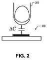
- FIG. 2illustrates a user finger interacting with a capacitive sensor.
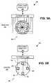
- FIG. 3Ais a block diagram illustrating a front side of a radial slider array of a radial capacitive sense interface, in accordance with an embodiment of the invention.
- FIG. 3Bis a block diagram illustrating a backside of a radial slider array of a radial capacitive sense interface, in accordance with an embodiment of the invention.
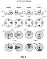
- FIG. 4is a diagram illustrating capacitive position and scroll operation of a radial capacitive sense interface, in accordance with an embodiment of the invention.
- FIG. 5is a diagram illustrating mechanical button operation of a radial capacitive sense interface, in accordance with an embodiment of the invention.
- FIG. 6is a flow chart illustrating a process for registering a center key actuation without aid of mechanical buttons, in accordance with an embodiment of the invention.
- FIG. 7Ais a block diagram illustrating a center key actuation using radial capacitive sensors without aid of a center mechanical button, in accordance with an embodiment of the invention.
- FIG. 7Bis a block diagram illustrating a possible capacitive sensor actuation pattern for registering a center key actuation, in accordance with an embodiment of the invention.
- FIG. 7Cis a block diagram illustrating another possible capacitive sensor actuation pattern for registering a center key actuation, in accordance with an embodiment of the invention.
- FIG. 8is a flow chart illustrating a process for registering a center key actuation with aid of off-center mechanical buttons, in accordance with an embodiment of the invention.
- FIG. 9is a block diagram illustrating a center key actuation using radial capacitive sensors with aid of off-center mechanical buttons, in accordance with an embodiment of the invention.
- FIG. 10is a functional block diagram illustrating a demonstrative processing system for implementing a capacitive sense user interface, in accordance with an embodiment of the invention.
- FIG. 11is a circuit diagram illustrating a demonstrative capacitance sensor, in accordance with an embodiment of the invention.
- Embodiments of a method, apparatus, and system for implementing a center key on a radial capacitive sense interface without a distinct center mechanical buttonare described herein.
- numerous specific detailsare set forth to provide a thorough understanding of the embodiments.
- One skilled in the relevant artwill recognize, however, that the techniques described herein can be practiced without one or more of the specific details, or with other methods, components, materials, etc.
- well-known structures, materials, or operationsare not shown or described in detail to avoid obscuring certain aspects.
- FIG. 2illustrates how capacitive sensors operate.
- FIG. 2illustrates a user finger 205 interacting with a capacitive sensor 200 .
- a conductive objectsuch as user finger 205
- its baseline capacitanceis increased, resulting in a measurable capacitance change.
- capacitive sensor activationscan be determined and registered within software.
- a user interaction with capacitive sensor 200is not limited to a finger.
- Other conductive objectsmay be used to interact with capacitive sensor 200 including, a stylus, a pen, or any other conductive object.
- capacitive sensor arraysmay be used to implement user interfaces of a variety of products including: door switches, white goods (e.g., kitchen appliances), laptop computers, desktop computers, personal digital assistants (“PDAs”), portable music players (e.g., MP3 players), wireless telephones, cellular telephones, radios, or the like.
- Capacitive sensor arraysmay also be used to implement position sensors.
- FIGS. 3A and 3Billustrate a radial capacitive sense (“CAP-sense”) interface 300 with a radial slider array 305 , in accordance with an embodiment of the invention.
- FIG. 3Aillustrates a front side 310 of radial slider array 305
- FIG. 3Billustrates a back side 315 of radial slider array 305 .
- the illustrated embodiment of radial CAP-sense interface 300includes CAP sensors 320 , input/output (“I/O”) interfaces 325 A and 325 B (collectively 325 ), a capacitance sensor circuit 330 , off-center mechanical buttons 335 , and a mechanical sensor circuit 340 .
- I/Oinput/output
- the illustrated embodiment of radial slider array 305includes CAP sensors 320 as being uninterrupted CAP sensors that radially extend all the way to the center of radial slider array 305 , without interruption. It is noteworthy that the illustrated embodiments of CAP sensors 320 are not oriented within an annulus shape encircling a center mechanical button; however, embodiments may include a small center portion cut out so CAP sensors 320 do not electrically short. Rather, the illustrated embodiment of radial slider array 305 implements the functionality of a center mechanical button with CAP sensors 320 , and in some embodiments, in connection with off-center mechanical buttons 335 . Activation of this pseudo-center button is referred to herein as registering a “center key activation”.
- Radial slider array 305is illustrated as a perfect circle; however, embodiments of radial slider array 305 need not be perfect circles. In fact, some embodiments may assume irregular circular-like shapes including an oval, an ellipse, or other more irregular shapes with multiple radial curvatures at different radial positions.
- I/O interface 325 Alinks each CAP sensor 320 to capacitance sensor circuit 330 .
- I/O interface 325 Blinks each off-center mechanical button 335 to mechanical sensor circuit 340 .
- I/O interfaces 325 A and 325 Bmay be implemented with a single I/O interface that couples to both capacitance sensor circuit 330 and mechanical sensor circuit 340 .
- I/O interfaces 325 A and 325 Bare distinct interfaces.
- I/O interface 325 Ais a configurable analog interconnect between capacitance sensor circuit 330 and radial slider array 305 .
- I/O interface 325 Acan be configured on the fly during regular operation to couple capacitance sensor circuit 330 to any one individual CAP sensor 320 at a time or to groups of CAP sensors 320 at a time.
- capacitive sensor circuit 330can measure the capacitance of CAP sensors 320 to determine whether its/their capacitance has deviated by a threshold amount for a threshold period of time, thus indicating that a user activation should be registered in software (i.e., acknowledged in software such that an appropriate action or function is executed).
- CAP sensor circuit 330includes driver circuitry of a relaxation oscillator.
- the driver circuitry within CAP sensor circuit 330continually charges and discharges each CAP sensor 320 by reciprocally driving and discharging a current onto CAP sensors 320 .
- I/O interface 325 Aconnects the driver circuitry to a particular CAP sensor 320 (or a group of CAP sensors 320 )
- the relaxation oscillator circuitis formed.
- the capacitance of the particular CAP sensor 320 connecteddetermines the frequency at which the relaxation oscillator circuit will oscillate.
- capacitance sensor circuit 330measures either a frequency change or period change of the oscillation associated with a particular CAP sensor 320 from a baseline value.
- CAP sensor circuit 330need not actually measure the absolute capacitance of a CAP sensor 320 to register an actuation, but rather can measure a value indicative of this capacitance. This value may be a simple count deviation from a baseline unactuated count value related to the period or frequency of oscillation.
- CAP sensor circuit 330may be implemented with a variety of other capacitive sense technologies including a current versus voltage phase shift measurement technique, a resistor-capacitor charge timing technique, a capacitive bridge divider technique, a charge transfer technique, or the like, described in greater detail below.
- CAP sensor circuit 330senses that one or more CAP sensors 320 are being actuated (e.g., threshold change in a baseline capacitance for a threshold duration), then the physical location of the user interaction on radial slider array 305 may be determined by analyzing the values measured by CAP sensor circuit 330 to determine which CAP sensors 320 are being actuated.
- I/O interface 325 Blinks each off-center mechanical button 335 to mechanical sensor circuit 340 .
- Mechanical buttons 335may be typical dome switches that provide force feedback to the user in the form of a spring with an audible “click” noise when actuated.
- Mechanical sensor circuit 340is coupled via I/O interface 325 B to sense actuations of off-center mechanical buttons 335 and provide a signal to software, which can then register (i.e., acknowledge) the actuation.
- FIG. 3Billustrates off-center mechanical buttons 335 disposed in the “cardinal positions” to implement up, down, left, and right functions.
- off-center mechanical buttons 335may be positioned in other off-center locations, and may include fewer or more buttons.
- CAP-sense interface 300need not even include off-center mechanical buttons 335 or I/O interface 325 B.
- CAP sensors 320are disposed on a top side 310 of a circularly shaped rigid substrate 350 , while off-center mechanical buttons 335 are disposed on backside 315 of rigid substrate 350 .
- rigid substrate 350is a printed circuit board (“PCB”).
- capacitance sensor circuit 330 and mechanical sensor circuit 340are embodied within one or more integrated circuits that are disposed on backside 315 of rigid substrate 350 along side off-center mechanical buttons 335 .
- capacitance sensor circuit 330 and mechanical sensor circuit 340are embodied within one or more integrated circuits electrically coupled to radial slider array 305 , but remotely located off rigid substrate 350 .
- FIG. 4is a diagram illustrating capacitive position and scroll operation of CAP-sense interface 300 , in accordance with an embodiment of the invention.
- FIG. 4illustrates columns 1 - 4 , each illustrating, respective, user interactions 405 A, 405 B, 405 C, and 405 D with radial slider array 305 .
- FIG. 4illustrates side views of rigid substrate 350 that does not include off-center mechanical buttons 335 disposed thereon. Note, only a portion of some elements are labeled so as not to clutter the drawings.
- Column 1illustrates a user finger generating a user interaction 405 A with radial slider array 305 .
- User interaction 405 Ais positioned on the right side of radial slider array 305 and actuates three CAP sensors 320 (illustrated with shading).
- User interaction 405 Asubstantially overlaps two CAP sensors 320 (illustrated with the darkest shading) and therefore capacitance sensor circuit 330 will measure the greatest capacitance deviation AC for these two CAP sensors 320 .
- User interaction 405 Amarginally overlaps another CAP sensor 320 (illustrated with lighter shading) and therefore capacitance sensor circuit 330 will measure a smaller capacitance deviation AC for this CAP sensor 320 .
- user interaction 405 Aonly marginally overlaps the lightly shaded CAP sensor 320 , the degree of interaction is still sufficient for capacitance sensor circuit 330 to sense an actuation of this CAP sensor 320 .
- Columns 2 , 3 , and 4illustrate similar positional user interactions as column 1 .
- Column 2illustrates user interaction 405 B positioned on a left side of radial slider array 305 .
- Column 3illustrates user interaction 405 C positioned on an upper side of radial slider array 305 .
- Column 4illustrates user interaction 405 D positioned on a lower side of radial slider array 305 .
- the position of a user interaction with radial slider array 305can be determined.
- Scroll operationmay be effected when the user interaction is slid around radial slider array 305 .
- Software entitiesmay measure the rate of the sliding motion to translate the sliding motion into a variable speed scrolling function.
- FIG. 5is a diagram illustrating mechanical button operation of radial CAP-sense interface 300 , in accordance with an embodiment of the invention.
- FIG. 5illustrates columns 1 - 4 , each illustrating, respective, user interactions 505 A, 505 B, 505 C, and 505 D with radial slider array 305 .
- FIG. 5illustrates side views of rigid substrate 350 that include off-center mechanical buttons 335 disposed thereon.
- FIG. 5illustrates how a user finger applies a force to front side 310 of radial slider array 305 at an interaction location.
- the forceis translated through substrate 350 , causing one or more of off-center mechanical buttons 335 disposed on backside 315 of rigid substrate 350 to be actuated.
- Column 1illustrates a user finger applying a force to front side 310 of radial slider array 305 at an interaction location 505 A.
- Interaction location 505 Ais positioned on the right side of radial slider array 305 and actuates three CAP sensors 320 (illustrated with shading).
- the forceis also translated through substrate 350 to the off-center mechanical button 335 located on the right (illustrated with black shading).
- Columns 2 , 3 , and 4illustrate similar actuations of other off-center mechanical buttons 335 , as column 1 .
- Column 2illustrates user interaction 505 B positioned on a left side of radial slider array 305 to actuate the left mechanical button.
- Column 3illustrates user interaction 505 C positioned on a upper side of radial slider array 305 to actuate the upper mechanical button.
- Column 4illustrates user interaction 505 D positioned on a lower side of radial slider array 305 to actuate the lower mechanical button.
- applying a force to front side 310 of radial slider array 305 to trigger an actuation of off-center mechanical buttons 335includes the side effect of actuating one or more CAP sensors 320 coincident or partially coincident with the location where the user applies the actuation force.
- FIG. 6is a flow chart illustrating a process 600 for registering a center key actuation on radial slider array 305 without aid of mechanical buttons, in accordance with an embodiment of the invention.
- the order in which some or all of the process blocks appear in each processshould not be deemed limiting. Rather, one of ordinary skill in the art having the benefit of the present disclosure will understand that some of the process blocks may be executed in a variety of orders not illustrated.
- FIGS. 7A , 7 B, and 7 Ceach illustrate possible CAP sensor actuation patterns for registering a center key actuation, as opposed to a simple actuation of CAP sensors 320 for positional or scrolling operations.
- a userinteracts with radial CAP-sense interface 300 by bring a conductive object (e.g., user's finger) in proximity to front side 310 of slider array 305 .
- FIG. 7Aillustrates one possible physical location 705 of a user interaction with radial slider array 305 .
- the user interaction at location 705may cause capacitance sensor circuit 330 to sense a number of concurrent actuations of CAP sensors 320 , as illustrated by the shading.
- the darker shadingconnotes a greater capacitance change AC for the particular CAP sensor 320 from its baseline capacitance, which is related to its degree of coincidence with location 705 .
- lighter shadingconnotes smaller capacitance changes AC for the particular CAP sensor 320 .
- a center key actuationis registered (process block 615 ). Registering an actuation is equivalent to software/firmware acknowledging or accepting that a center key actuation event has occurred.
- the threshold numbermay be equal to two or more concurrently actuated CAP sensors 320 . In one embodiment, the threshold number is equal to at least three CAP sensors 320 within radial slider array 305 being concurrently actuated. In other embodiments, the threshold number may be greater or smaller as a proportion of all CAP sensors 320 .
- CAP sensor 320may be used to determine whether a user intended to initiate a center key actuation.
- secondary conditionsmay be alternative conditions used instead of the primary condition, or may be used in addition to the primary condition.
- the secondary conditionsmay be implemented using an inclusive (or exclusive) logical OR between the primary condition and one or more secondary conditions.
- the primary conditioncould be logically AND'd with one or more secondary conditions to register a center key actuation.
- a secondary conditionis logically OR'd to decision block 610 . If there are not a threshold number of concurrently actuated CAP sensors 320 , then process 600 continues to a decision block 620 (a secondary condition). In decision block 620 , if multiple non-radially adjacent CAP sensors 320 are concurrently actuated, then a center key actuation is registered in process block 615 . Otherwise, process 600 continues to a process block 625 where a regular actuation of one of CAP sensors 320 is registered.
- FIG. 7Aillustrates a typical actuation pattern where at least a threshold number of CAP sensors 320 are concurrently actuated by a user interaction 705 .
- user interaction 705is not perfectly centered on radial slider array 305 , a center key actuation will still result since a large portion of CAP sensors 320 are actuated.
- capacitance sensor circuit 330will measure varying capacitance deviations for each CAP sensor 320 .
- software algorithmscan analyze the variations in the capacitance deviations of multiple concurrent actuations of CAP sensors 320 to discern typical center key activation patterns, and therefore determine with a greater degree of reliability, as to whether a user intended to trigger a center key actuation.
- FIGS. 7B and 7Cillustrate other actuation patterns that could trigger a center key actuation. Both actuation patterns include concurrently actuated CAP sensors 320 that are physically non-radially adjacent and radially separated by intervening unactuated CAP sensors 320 . Other actuation patterns may be used to determine a center key actuation, as well.
- FIG. 8is a flow chart illustrating a process 800 for registering a center key actuation with aid of off-center mechanical buttons 335 , in accordance with an embodiment of the invention. Process 800 is described with reference to FIG. 9 .
- a userinteracts with radial CAP-sense interface 300 by bring a conductive object (e.g., user's finger) in proximity to front side 310 of slider array 305 .
- FIG. 9illustrates an example user interaction 905 with radial slider array 305 .
- a decision block 810it is determined whether one of off-center mechanical buttons 335 is actuated due to the user interaction. In other words, it is determined whether the user applied enough force to front side 310 to cause one or more off-center mechanical buttons 335 to actuate. If not, then a regular capacitive actuation of one or more CAP sensors 320 is registered (process block 815 ) for positional or scrolling purposes.
- process 800continues to a decision block 820 .
- decision block 820it is determined whether user interaction 905 has actuated at least a threshold number of CAP sensors 320 concurrently. If yes, then a center key actuation is registered in process block 825 . If no, then an activation of one of off-center mechanical buttons 335 is registered in process block 830 .
- Similar threshold numbers and actuation patternsmay be applied in process 800 , as discuss above in connection with process 600 .
- both primary and secondary conditionsmay be applied using logical AND or logical OR (inclusive or exclusive) functions.
- Process 800operates similar to process 600 , except the user must additionally apply enough force to front side 310 of radial slider array 305 to actuate one of off-center mechanical buttons 335 . Accordingly, process 800 makes unintended center key actuations less likely.
- Processes 600 and 800illustrate techniques to implement the functionality of a center button (e.g., a center mechanical dome switch) without need of a physically distinct button or capacitance sensor designated for the purpose of a center button function.
- a center buttone.g., a center mechanical dome switch
- CAP sensors 320can extend all the way to the center and are therefore larger.
- a larger surface area for each CAP sensor 320results in a more sensitive CAP-sense interface 300 .
- CAP-sense interface 300implements the same functionality of conventional circular slider interface 105 with fewer components, radial CAP-sense interface 300 may be less costly to manufacture.
- Eliminating a center mechanical buttonalso eliminates one possible failure point in the design, since mechanical components tend to be more failure prone than electrical components. Finally, eliminating an electrically distinct center button or mechanical button, reduces the number of I/O ports required in I/O interface 325 B.
- FIG. 10is a functional block diagram illustrating a demonstrative system 1000 for implementing a capacitance sense user interface, in accordance with an embodiment of the invention.
- System 1000includes a processing device 1010 , a capacitive sense pad 1020 , a capacitive sense linear slider 1030 , a capacitive sense radial slider 1040 , a host processor 1050 , an embedded controller 1060 , and non-capacitance sensor elements 1070 .
- Processing device 1010may include analog and/or digital general purpose input/output (“GPIO”) ports 1007 .
- GPIO ports 1007may be programmable.
- GPIO ports 1007may be coupled to a Programmable Interconnect and Logic (“PIL”), which acts as an interconnect between GPIO ports 1007 and a digital block array of processing device 1010 (not illustrated).
- PILProgrammable Interconnect and Logic
- the digital block arraymay be configured to implement a variety of digital logic circuits (e.g., DAC, digital filters, digital control systems, etc.) using, in one embodiment, configurable user modules (“UMs”).
- UMsconfigurable user modules
- the digital block arraymay be coupled to a system bus.
- Processing device 1010may also include memory, such as random access memory (RAM) 1005 and program flash 1004 .
- RAMrandom access memory
- program flash 1004program flash
- RAM 1005may be static RAM (“SRAM”), and program flash 1004 may be a non-volatile storage, which may be used to store firmware (e.g., control algorithms executable by processing core 1002 to implement operations described herein such as the aforementioned decision algorithm).
- Processing device 1010may also include a memory controller unit (“MCU”) 1003 coupled to memory and the processing core 1002 .
- MCUmemory controller unit
- Processing device 1010may also include an analog block array (not illustrated).
- the analog block arrayis also coupled to the system bus.
- the analog block arrayalso may be configured to implement a variety of analog circuits (e.g., ADC, analog filters, etc.) using, in one embodiment, configurable UMs.
- the analog block arraymay also be coupled to the GPIO 1007 .
- capacitance sensor 1001may be integrated into processing device 1010 .
- Capacitance sensor 1001may include analog I/O (e.g., I/O interfaces 325 ) for coupling to an external component, such as capacitive sense pad 1020 , capacitive sense linear slider 1030 , capacitive sense radial slider 1040 (e.g., radial slider array 305 ), and/or other devices.
- I/Oe.g., I/O interfaces 325
- Capacitance sensor 1001is described in more detail below.
- Processing device 1010may include internal oscillator/clocks 1006 and communication block 1008 .
- the oscillator/clocks block 1006provides clock signals to one or more of the components of processing device 1010 .
- Communication block 1008may be used to communicate with an external component, such as a host processor 1050 , via host interface (I/F) line 1051 .
- processing device 1010may also be coupled to embedded controller 1060 to communicate with the external components, such as host 1050 .
- Interfacing to the host 1050can be through various methods. In one exemplary embodiment, interfacing with the host 1050 may be done using a standard PS/2 interface to connect to embedded controller 1060 , which in turn sends data to the host 1050 via low pin count (LPC) interface.
- LPClow pin count
- processing device 1010may do both touch-sensor pad and keyboard control operations, thereby freeing up the embedded controller 1060 for other housekeeping functions.
- interfacingmay be done using a universal serial bus (USB) interface directly coupled to host 1050 via host interface line 1051 .
- processing device 1010may communicate to external components, such as host 1050 using industry standard interfaces, such as USB, PS/2, inter-integrated circuit (I2C) bus, or system packet interfaces (SPI).
- Host 1050 and/or embedded controller 1060may be coupled to processing device 1010 with a ribbon or flex cable from an assembly, which houses the sensing device and processing device.
- processing device 1010is configured to communicate with embedded controller 1060 or host 1050 to send and/or receive data.
- the datamay be a command or alternatively a signal.
- system 1000may operate in both standard-mouse compatible and enhanced modes.
- the standard-mouse compatible modeutilizes the HID class drivers already built into the Operating System (OS) software of host 1050 . These drivers enable processing device 1010 and sensing device to operate as a standard cursor control user interface device, such as a two-button PS/2 mouse.
- the enhanced modemay enable additional features such as scrolling (reporting absolute position) or disabling the sensing device, such as when a mouse is plugged into the notebook.
- processing device 1010may be configured to communicate with embedded controller 1060 or host 1050 , using non-OS drivers, such as dedicated touch-sensor pad drivers, or other drivers known by those of ordinary skill in the art.
- Processing device 1010may reside on a common carrier substrate such as, for example, an integrated circuit (IC) die substrate, a multi-chip module substrate, or the like. Alternatively, the components of processing device 1010 may be one or more separate integrated circuits and/or discrete components. In one exemplary embodiment, processing device 1010 may be a Programmable System on a Chip (PSoCTM) processing device, manufactured by Cypress Semiconductor Corporation, San Jose, Calif. Alternatively, processing device 1010 may be one or more other processing devices known by those of ordinary skill in the art, such as a microprocessor or central processing unit, a controller, special-purpose processor, digital signal processor (“DSP”), an application specific integrated circuit (“ASIC”), a field programmable gate array (“FPGA”), or the like. In an alternative embodiment, for example, processing device 1010 may be a network processor having multiple processors including a core unit and multiple microengines. Additionally, processing device 1010 may include any combination of general-purpose processing device(s) and special-purpose processing device(s).
- Capacitance sensor 1001may be integrated into the IC of processing device 1010 , or alternatively, in a separate IC. Descriptions of capacitance sensor 1001 may be generated and compiled for incorporation into other integrated circuits. For example, behavioral level code describing capacitance sensor 1001 , or portions thereof, may be generated using a hardware descriptive language, such as VHDL or Verilog, and stored to a machine-accessible medium (e.g., CD-ROM, hard disk, floppy disk, etc.). Furthermore, the behavioral level code can be compiled into register transfer level (“RTL”) code, a netlist, or even a circuit layout and stored to a machine-accessible medium. The behavioral level code, the RTL code, the netlist, and the circuit layout all represent various levels of abstraction to describe capacitance sensor 1001 .
- VHDLhardware descriptive language
- Verilogmachine-accessible medium
- RTLregister transfer level
- electronic system 1000may be used in a notebook computer.
- system 1000may be used in other applications, such as a mobile handset, a personal data assistant (PDA), a keyboard, a television, a remote control, a monitor, a handheld multi-media device, a handheld video player, a handheld gaming device, or a control panel.
- PDApersonal data assistant
- capacitance sensor 1001may be a capacitive switch relaxation oscillator (CSR).
- CSRmay have an array of capacitive touch switches using a current-programmable relaxation oscillator, an analog multiplexer, digital counting functions, and high-level software routines to compensate for environmental and physical switch variations.
- the CSRmay include physical, electrical, and software components.
- the physical componentmay include the physical switch itself, typically a pattern constructed on a printed circuit board (“PCB”) with an insulating cover, a flexible membrane, or a transparent overlay.
- the electrical componentmay include an oscillator or other means to convert a changed capacitance into a measured signal.
- the electrical componentmay also include a counter or timer to measure the oscillator output.
- the software componentmay include detection, compensation, and decision software algorithms to convert the count value into a capacitive sensor detection decision.
- the current versus voltage phase shift measurementmay include driving the capacitance through a fixed-value resistor to yield voltage and current waveforms that are out of phase by a predictable amount.
- the drive frequencycan be adjusted to keep the phase measurement in a readily measured range.
- the resistor-capacitor charge timingmay include charging the capacitor through a fixed resistor and measuring timing on the voltage ramp. Small capacitor values may require very large resistors for reasonable timing.
- the capacitive bridge dividermay include driving the capacitor under test through a fixed reference capacitor. The reference capacitor and the capacitor under test form a voltage divider.
- the voltage signalis recovered with a synchronous demodulator, which may be done in processing device 1010 .
- the charge transfermay be conceptually similar to an R-C charging circuit.
- Cpis the capacitance being sensed and C SUM is the summing capacitor, into which charge is transferred on successive cycles.
- C SUMis the summing capacitor, into which charge is transferred on successive cycles.
- the voltage on C SUMis reset.
- the voltage on C SUMincreases exponentially (and only slightly) with each clock cycle. The time for this voltage to reach a specific threshold is measured with a counter.
- FIG. 11illustrates one possible embodiment of capacitance sensor 1001 implemented with a relaxation oscillator circuit 1100 .
- the illustrated embodiment of capacitance sensor 1001includes relaxation oscillator circuit 1100 , an analog multiplexor (“MUX”) bus 1101 , a sensor array 1110 , and a digital counter 1120 .
- MUXanalog multiplexor
- Analog MUX bus 1101 and selection circuit 1130may collectively implement the functionality of I/O interfaces 325 .
- the remaining portions of relaxation oscillator 1100 and digital counter 1120may implement the functionality of capacitance sensor circuit 330 .
- Sensor array 1110may represent radial slider array 305 and the individual capacitor sensors 1151 may represent the individual CAP sensors 320 .
- Relaxation oscillator 1100is formed by the capacitance to be measured on capacitor sensors 1151 , a charging current source 1152 , a comparator 1153 , and a reset switch 1154 .
- capacitor sensor 1151are representative of the capacitance measured on a sensor element of a CAP sensor array.
- the relaxation oscillatoris coupled to drive a charging current Ic in a single direction onto a device under test (“DUT”) capacitor, any of capacitor sensors 1151 .
- DUTdevice under test
- Equation (1)describes the relation between current, capacitance, voltage and time for a charging capacitor.
- CdVI C dt (1)
- the relaxation oscillatorbegins by charging the capacitor sensor 1151 from a ground potential or zero voltage and continues to pile charge on the capacitor 1151 at a fixed charging current Ic until the voltage across the capacitor 1151 at node 1170 reaches a reference voltage or threshold voltage, V TH 1155 .
- V TH 1155the relaxation oscillator allows the accumulated charge at node 1155 to discharge (e.g., the capacitor 1151 to “relax” back to the ground potential) and then the process repeats itself.
- the output of comparator 1153asserts a clock signal F OUT 1156 (e.g., F OUT 1156 goes high), which enables the reset switch 1154 . This resets the voltage on the capacitor at node 1170 to ground and the charge cycle starts again.
- the relaxation oscillatoroutputs a relaxation oscillator clock signal (F OUT 1156 ) having a frequency (f RO ) dependent upon capacitance C of the capacitor 1151 and charging current Ic.
- the comparator trip time of the comparator 1153 and reset switch 1154add a fixed delay.
- the output of the comparator 1153is synchronized with a reference system clock to guarantee that the comparator reset time is long enough to completely reset the charging voltage on capacitor 1155 .
- f ROwill change proportionally according to Equation (1).
- f REFfrequency of a known reference system clock signal
- equations (2) and (3) belowdescribe that a change in frequency between F OUT 1156 and REF CLK is proportional to a change in capacitance of the capacitor 1151 .
- ⁇ C ⁇ 1/ ⁇ f, where (2) ⁇ ff RO ⁇ f REF .
- a frequency comparatormay be coupled to receive relaxation oscillator clock signal (F OUT 1156 ) and REF CLK, compare their frequencies f RO and f REF , respectively, and output a signal indicative of the difference ⁇ f between these frequencies. By monitoring ⁇ f one can determine whether the capacitance of the capacitor 1151 has changed.
- the relaxation oscillator 950may be built using a programmable timer (e.g., 555 timer) to implement the comparator 1153 and reset switch 1154 .
- the relaxation oscillator 1100may be built using other circuits.
- Sensor array 1110includes a plurality of sensor elements 1155 ( 1 )- 1155 (N), where N is a positive integer value that represents the number of capacitive sensors within any of capacitive sense pad 1020 , capacitive sense linear slider 1030 , or capacitive sense circular slider 1040 .
- Relaxation oscillator 1100further includes a selection circuit 1130 .
- Selection circuit 1130is coupled to the plurality of sensor elements 1151 ( 1 )- 1151 (N), the reset switch 1154 , the current source 1152 , and the comparator 1153 .
- Selection circuit 1130may be used to allow the relaxation oscillator 1100 to measure capacitance on multiple sensor elements (e.g., rows or columns).
- the selection circuit 1130may be configured to sequentially select a sensor element of the plurality of sensor elements to provide the charge current and to measure the capacitance of each sensor element.
- selection circuit 1130is a multiplexer array of the relaxation oscillator 1100 .
- selection circuitmay be other circuitry outside the relaxation oscillator 1100 , or even outside the capacitance sensor 1001 to select the sensor element to be measured.
- Capacitance sensor 1001may include one relaxation oscillator and digital counter for the plurality of sensor elements of the sensor array.
- capacitance sensor 1001may include multiple relaxation oscillators and digital counters to measure capacitance on the plurality of sensor elements of the sensor array.
- the multiplexer arraymay also be used to ground the sensor elements that are not being measured. This may be done in conjunction with a dedicated pin in the GPI0 port 1007 .
- the capacitance sensor 1001may be configured to simultaneously scan the sensor elements, as opposed to being configured to sequentially scan the sensor elements as described above.
- the sensing devicemay include a sensor array having a plurality of rows and columns. The rows may be scanned simultaneously, and the columns may be scanned simultaneously.
- the voltages on all of the rows of the sensor arrayare simultaneously moved, while the voltages of the columns are held at a constant voltage, with the complete set of sampled points simultaneously giving a profile of the conductive object in a first dimension.
- the voltages on all of the rowsare held at a constant voltage, while the voltages on all the rows are simultaneously moved, to obtain a complete set of sampled points simultaneously giving a profile of the conductive object in the other dimension.
- the voltages on all of the rows of the sensor arrayare simultaneously moved in a positive direction, while the voltages of the columns are moved in a negative direction.
- the voltages on all of the rows of the sensor arrayare simultaneously moved in a negative direction, while the voltages of the columns are moved in a positive direction.
- Digital counter 1120is coupled to the output of the relaxation oscillator 1100 .
- Digital counter 1120receives the relaxation oscillator output signal 1156 (F OUT ).
- Digital counter 1120is configured to count at least one of a frequency or a period of the relaxation oscillator output received from the relaxation oscillator.
- the digital counter 1120may include two multiplexers 1123 and 1124 . Multiplexers 1123 and 1124 are configured to select the inputs for the PWM 1121 and the timer 1122 for the two measurement methods, frequency and period measurement methods. Alternatively, other selection circuits may be used to select the inputs for the PWM 1121 and the time 1122 . In another embodiment, multiplexers 1123 and 1124 are not included in the digital counter, for example, digital counter 1120 may be configured in one, or the other, measurement configuration.
- the relaxation oscillator output signal 1156is counted for a fixed period of time.
- the counter 1122is read to obtain the number of counts during the gate time. This method works well at low frequencies where the oscillator reset time is small compared to the oscillator period.
- a pulse width modulator (PWM) 1121is clocked for a fixed period by a derivative of the system clock, VC 3 1126 (which is a divider from system clock 1125 , e.g., 24 MHz). Pulse width modulation is a modulation technique that generates variable-length pulses to represent the amplitude of an analog input signal; in this case VC 3 1126 .
- the output of PWM 1121enables timer 1122 (e.g., 16-bit).
- the relaxation oscillator output signal 1156clocks the timer 1122 .
- the timer 1122is reset at the start of the sequence, and the count value is read out at the end of the gate period.
- the relaxation oscillator output signal 1156gates a timer 1122 , which is clocked by the system clock 1125 (e.g., 24 MHz). In order to improve sensitivity and resolution, multiple periods of the oscillator are counted with the PWM 1121 . The output of PWM 1121 is used to gate the timer 1122 . In this method, the relaxation oscillator output signal 1156 drives the clock input of PWM 1121 .
- pulse width modulationis a modulation technique that generates variable-length pulses to represent the amplitude of an analog input signal; in this case the relaxation oscillator output signal 1156 .
- the output of the PWM 1121enables timer 1122 (e.g., 16-bit), which is clocked at the system clock frequency 1125 (e.g., 24 MHz).
- timer 1122e.g., 16-bit
- the countstarts by releasing the capture control.
- the capture signalis asserted (e.g., goes high), stopping the count and setting the PWM's interrupt.
- the timer valueis read in this interrupt.
- the relaxation oscillator 1100is indexed to the next capacitive sensor (e.g., capacitor 1151 ( 2 )) to be measured and the count sequence is started again.
- the length of the counter 1122 and the detection time required for capacitance sensor 1001are determined by sensitivity requirements. Small changes in the capacitance on sensor element 1151 result in small changes in frequency. In order to find these small changes, it may be necessary to count for a considerable time.
- the capacitive sensorse.g., sensor elements 1151 ( 1 )-(N)
- the count values for each capacitive sensors with no actuationare stored as a baseline array (Cp).
- the presence of a finger on the switchis determined by the difference in counts between a stored value for no capacitive sensors actuation and the acquired value with capacitive sensors actuation, referred to here as ⁇ n.
- the sensitivity of a single capacitive sensorsis approximately:
- ⁇ ⁇ ⁇ n nCf Cp ( 4 )
- the value of ⁇ nshould be large enough for reasonable resolution and clear indication of capacitive sensors actuation.
- multiple sensor elementsmay be sequentially scanned to provide current to and measure the capacitance from the capacitors (e.g., sensor elements), as previously described. In other words, while one sensor element is being measured, the remaining sensor elements are grounded using the GPIO port 1007 .
- This drive and multiplex arrangementbypasses the existing GPIO to connect the selected pin to an internal analog multiplexer (mux) bus.
- the capacitor charging current (e.g., current source 1152 ) and reset switch 1153are connected to the analog mux bus. This may limit the pin-count requirement to simply the number of capacitive sensors (e.g., capacitors 1151 ( 1 )- 1151 (N)) to be addressed. In one exemplary embodiment, no external resistors or capacitors are required inside or outside the processing device 1110 to enable operation.
- the capacitor charging current for the relaxation oscillator 1100is generated in a register programmable current output DAC (also known as IDAC). Accordingly, the current source 1152 is a current DAC or IDAC.
- the IDAC output currentmay be set by an 8-bit value provided by the processing device 1010 , such as from the processing core 1002 .
- the 8-bit valuemay be stored in a register or in memory.
- the oscillator-reset timemay add to the oscillator period (especially at higher frequencies); and there may be some variation to the magnitude of the IDAC output current with operating frequency. Accordingly, the optimum oscillation frequency and operating current for a particular switch array may be determined to some degree by experimentation.
Landscapes
- Engineering & Computer Science (AREA)
- General Engineering & Computer Science (AREA)
- Theoretical Computer Science (AREA)
- Human Computer Interaction (AREA)
- Physics & Mathematics (AREA)
- General Physics & Mathematics (AREA)
- Electronic Switches (AREA)
Abstract
Description
CdV=ICdt (1)
ΔC∝1/Δf, where (2)
Δf=fRO−fREF. (3)
The value of Δn should be large enough for reasonable resolution and clear indication of capacitive sensors actuation.
Claims (20)
Priority Applications (1)
| Application Number | Priority Date | Filing Date | Title |
|---|---|---|---|
| US11/489,944US7253643B1 (en) | 2006-07-19 | 2006-07-19 | Uninterrupted radial capacitive sense interface |
Applications Claiming Priority (1)
| Application Number | Priority Date | Filing Date | Title |
|---|---|---|---|
| US11/489,944US7253643B1 (en) | 2006-07-19 | 2006-07-19 | Uninterrupted radial capacitive sense interface |
Publications (1)
| Publication Number | Publication Date |
|---|---|
| US7253643B1true US7253643B1 (en) | 2007-08-07 |
Family
ID=38324351
Family Applications (1)
| Application Number | Title | Priority Date | Filing Date |
|---|---|---|---|
| US11/489,944Expired - Fee RelatedUS7253643B1 (en) | 2006-07-19 | 2006-07-19 | Uninterrupted radial capacitive sense interface |
Country Status (1)
| Country | Link |
|---|---|
| US (1) | US7253643B1 (en) |
Cited By (77)
| Publication number | Priority date | Publication date | Assignee | Title |
|---|---|---|---|---|
| US20060007146A1 (en)* | 2004-06-16 | 2006-01-12 | Chic Technology Corp. | Electrodes touching mouse |
| US20070052044A1 (en)* | 2005-09-06 | 2007-03-08 | Larry Forsblad | Scrolling input arrangements using capacitive sensors on a flexible membrane |
| US20070229468A1 (en)* | 2006-03-30 | 2007-10-04 | Cypress Semiconductor Corporation | Apparatus and method for reducing average scan rate to detect a conductive object on a sensing device |
| US20070268265A1 (en)* | 2006-05-18 | 2007-11-22 | Cypress Semiconductor Corporation | Two-pin buttons |
| US20080018596A1 (en)* | 2006-07-18 | 2008-01-24 | Jonah Harley | Capacitive sensing in displacement type pointing devices |
| US20080111714A1 (en)* | 2006-11-14 | 2008-05-15 | Viktor Kremin | Capacitance to code converter with sigma-delta modulator |
| US20080136792A1 (en)* | 2006-12-07 | 2008-06-12 | Tao Peng | Preventing unintentional activation of a touch-sensor button caused by a presence of conductive liquid on the touch-sensor button |
| US20080164076A1 (en)* | 2007-01-04 | 2008-07-10 | Timothy James Orsley | Capacitive sensing and absolute position mapping in displacement type pointing devices |
| US20080196945A1 (en)* | 2007-02-21 | 2008-08-21 | Jason Konstas | Preventing unintentional activation of a sensor element of a sensing device |
| US20080277171A1 (en)* | 2007-05-07 | 2008-11-13 | Wright David G | Reducing sleep current in a capacitance sensing system |
| US20090008161A1 (en)* | 2007-07-04 | 2009-01-08 | Jones Christopher W | Capacitive sensor array and gesture recognition |
| US20090009491A1 (en)* | 2007-07-04 | 2009-01-08 | Grivna Edward L | Capacitive sensing control knob |
| US20090107737A1 (en)* | 2007-10-28 | 2009-04-30 | Joesph K Reynolds | Multiple-sensor-electrode capacitive button |
| US20090160812A1 (en)* | 2007-12-21 | 2009-06-25 | Hsing-Chiang Huang | Electronic apparatus and input interface thereof |
| WO2009032898A3 (en)* | 2007-09-04 | 2009-09-17 | Apple Inc. | Compact input device |
| US20100026637A1 (en)* | 2008-07-31 | 2010-02-04 | Htc Corporation | Touch control electronic device and operating method thereof |
| US7710394B2 (en) | 2001-10-22 | 2010-05-04 | Apple Inc. | Method and apparatus for use of rotational user inputs |
| US7710393B2 (en) | 2001-10-22 | 2010-05-04 | Apple Inc. | Method and apparatus for accelerated scrolling |
| US7795553B2 (en) | 2006-09-11 | 2010-09-14 | Apple Inc. | Hybrid button |
| US20100289759A1 (en)* | 2009-05-15 | 2010-11-18 | Apple Inc. | Input device with optimized capacitive sensing |
| US20100295564A1 (en)* | 2009-05-22 | 2010-11-25 | Reynolds Joseph K | Capacitive sensing with combinatorial sensor layout |
| US7880729B2 (en) | 2005-10-11 | 2011-02-01 | Apple Inc. | Center button isolation ring |
| US7932897B2 (en) | 2004-08-16 | 2011-04-26 | Apple Inc. | Method of increasing the spatial resolution of touch sensitive devices |
| US8022935B2 (en) | 2006-07-06 | 2011-09-20 | Apple Inc. | Capacitance sensing electrode with integrated I/O mechanism |
| US20110242025A1 (en)* | 2010-04-02 | 2011-10-06 | Mstar Semiconductor, Inc. | Hand Gesture Recognition Method for Touch Panel and Associated Apparatus |
| US8040142B1 (en) | 2006-03-31 | 2011-10-18 | Cypress Semiconductor Corporation | Touch detection techniques for capacitive touch sense systems |
| US8058937B2 (en) | 2007-01-30 | 2011-11-15 | Cypress Semiconductor Corporation | Setting a discharge rate and a charge rate of a relaxation oscillator circuit |
| US8059099B2 (en) | 2006-06-02 | 2011-11-15 | Apple Inc. | Techniques for interactive input to portable electronic devices |
| US8089288B1 (en) | 2006-11-16 | 2012-01-03 | Cypress Semiconductor Corporation | Charge accumulation capacitance sensor with linear transfer characteristic |
| US8089289B1 (en) | 2007-07-03 | 2012-01-03 | Cypress Semiconductor Corporation | Capacitive field sensor with sigma-delta modulator |
| US8125461B2 (en) | 2008-01-11 | 2012-02-28 | Apple Inc. | Dynamic input graphic display |
| US8154310B1 (en)* | 2008-02-27 | 2012-04-10 | Cypress Semiconductor Corporation | Capacitance sensor with sensor capacitance compensation |
| US8159462B1 (en)* | 2006-11-15 | 2012-04-17 | Cypress Semiconductor Corporation | Reference voltage offset for capacitive touch-sensor measurement |
| US20120098793A1 (en)* | 2010-10-20 | 2012-04-26 | Pixart Imaging Inc. | On-screen-display module, display device, and electronic device using the same |
| US8169238B1 (en) | 2007-07-03 | 2012-05-01 | Cypress Semiconductor Corporation | Capacitance to frequency converter |
| US8209861B2 (en) | 2008-12-05 | 2012-07-03 | Flextronics Ap, Llc | Method for manufacturing a touch screen sensor assembly |
| US8228306B2 (en) | 2008-07-23 | 2012-07-24 | Flextronics Ap, Llc | Integration design for capacitive touch panels and liquid crystal displays |
| US8258986B2 (en) | 2007-07-03 | 2012-09-04 | Cypress Semiconductor Corporation | Capacitive-matrix keyboard with multiple touch detection |
| US8274486B2 (en) | 2008-12-22 | 2012-09-25 | Flextronics Ap, Llc | Diamond pattern on a single layer |
| US8274479B2 (en) | 2006-10-11 | 2012-09-25 | Apple Inc. | Gimballed scroll wheel |
| US8321174B1 (en) | 2008-09-26 | 2012-11-27 | Cypress Semiconductor Corporation | System and method to measure capacitance of capacitive sensor array |
| US8358142B2 (en) | 2008-02-27 | 2013-01-22 | Cypress Semiconductor Corporation | Methods and circuits for measuring mutual and self capacitance |
| US8395590B2 (en) | 2008-12-17 | 2013-03-12 | Apple Inc. | Integrated contact switch and touch sensor elements |
| US8416198B2 (en) | 2007-12-03 | 2013-04-09 | Apple Inc. | Multi-dimensional scroll wheel |
| US8446370B2 (en) | 2002-02-25 | 2013-05-21 | Apple Inc. | Touch pad for handheld device |
| US8446158B1 (en) | 2007-11-09 | 2013-05-21 | Cypress Semiconductor Corporation | Compensation for parasitic capacitance of a capacitive sensor |
| US8482530B2 (en) | 2006-11-13 | 2013-07-09 | Apple Inc. | Method of capacitively sensing finger position |
| US8487639B1 (en) | 2008-11-21 | 2013-07-16 | Cypress Semiconductor Corporation | Receive demodulator for capacitive sensing |
| US8514185B2 (en) | 2006-07-06 | 2013-08-20 | Apple Inc. | Mutual capacitance touch sensing device |
| US8525955B2 (en) | 2012-01-31 | 2013-09-03 | Multek Display (Hong Kong) Limited | Heater for liquid crystal display |
| US8525799B1 (en) | 2007-04-24 | 2013-09-03 | Cypress Semiconductor Conductor | Detecting multiple simultaneous touches on a touch-sensor device |
| US8525798B2 (en) | 2008-01-28 | 2013-09-03 | Cypress Semiconductor Corporation | Touch sensing |
| US8537132B2 (en) | 2005-12-30 | 2013-09-17 | Apple Inc. | Illuminated touchpad |
| US8552990B2 (en) | 2003-11-25 | 2013-10-08 | Apple Inc. | Touch pad for handheld device |
| US8570052B1 (en) | 2008-02-27 | 2013-10-29 | Cypress Semiconductor Corporation | Methods and circuits for measuring mutual and self capacitance |
| US8570053B1 (en) | 2007-07-03 | 2013-10-29 | Cypress Semiconductor Corporation | Capacitive field sensor with sigma-delta modulator |
| US8683378B2 (en) | 2007-09-04 | 2014-03-25 | Apple Inc. | Scrolling techniques for user interfaces |
| US8743060B2 (en) | 2006-07-06 | 2014-06-03 | Apple Inc. | Mutual capacitance touch sensing device |
| US8749493B2 (en) | 2003-08-18 | 2014-06-10 | Apple Inc. | Movable touch pad with added functionality |
| US8816967B2 (en) | 2008-09-25 | 2014-08-26 | Apple Inc. | Capacitive sensor having electrodes arranged on the substrate and the flex circuit |
| US8820133B2 (en) | 2008-02-01 | 2014-09-02 | Apple Inc. | Co-extruded materials and methods |
| US8866500B2 (en) | 2009-03-26 | 2014-10-21 | Cypress Semiconductor Corporation | Multi-functional capacitance sensing circuit with a current conveyor |
| US8872771B2 (en) | 2009-07-07 | 2014-10-28 | Apple Inc. | Touch sensing device having conductive nodes |
| US20150227163A1 (en)* | 2012-08-30 | 2015-08-13 | Delphi Technologies, Inc. | Control module comprising a touch-sensitive surface |
| US9128568B2 (en) | 2008-07-30 | 2015-09-08 | New Vision Display (Shenzhen) Co., Limited | Capacitive touch panel with FPC connector electrically coupled to conductive traces of face-to-face ITO pattern structure in single plane |
| JP2015191483A (en)* | 2014-03-28 | 2015-11-02 | ポリマテック・ジャパン株式会社 | Rotation input parts |
| US9268441B2 (en) | 2011-04-05 | 2016-02-23 | Parade Technologies, Ltd. | Active integrator for a capacitive sense array |
| US9285929B2 (en) | 2010-03-30 | 2016-03-15 | New Vision Display (Shenzhen) Co., Limited | Touchscreen system with simplified mechanical touchscreen design using capacitance and acoustic sensing technologies, and method therefor |
| US9367151B2 (en) | 2005-12-30 | 2016-06-14 | Apple Inc. | Touch pad with symbols based on mode |
| US9417728B2 (en) | 2009-07-28 | 2016-08-16 | Parade Technologies, Ltd. | Predictive touch surface scanning |
| US9454256B2 (en) | 2008-03-14 | 2016-09-27 | Apple Inc. | Sensor configurations of an input device that are switchable based on mode |
| US9500686B1 (en) | 2007-06-29 | 2016-11-22 | Cypress Semiconductor Corporation | Capacitance measurement system and methods |
| US9582078B1 (en)* | 2013-06-28 | 2017-02-28 | Maxim Integrated Products, Inc. | Integrated touchless joystick-type controller |
| US20170090610A1 (en)* | 2015-09-29 | 2017-03-30 | Synaptics Incorporated | Row-based sensing on matrix pad sensors |
| US9753570B2 (en) | 2014-03-14 | 2017-09-05 | Synaptics Incorporated | Combined capacitive sensing |
| US20170307924A1 (en)* | 2015-09-15 | 2017-10-26 | Boe Technology Group Co., Ltd. | Touch control electrode structure, touch screen and display apparatus |
| US11093093B2 (en) | 2014-03-14 | 2021-08-17 | Synaptics Incorporated | Transcapacitive and absolute capacitive sensing profiles |
Citations (150)
| Publication number | Priority date | Publication date | Assignee | Title |
|---|---|---|---|---|
| US4264903A (en)* | 1978-06-12 | 1981-04-28 | General Electric Company | Capacitive touch control and display |
| US4283713A (en) | 1979-01-15 | 1981-08-11 | Tektronix, Inc. | Waveform acquisition circuit |
| US4438404A (en) | 1982-01-04 | 1984-03-20 | Tektronix, Inc. | Signal sampling system |
| US4475151A (en) | 1982-11-04 | 1984-10-02 | Harald Philipp | Switching amplifier circuit |
| US4497575A (en) | 1982-11-01 | 1985-02-05 | Tektronix, Inc. | Optical fiber test instrument calibrator |
| US4736191A (en)* | 1985-08-02 | 1988-04-05 | Karl E. Matzke | Touch activated control method and apparatus |
| US4736097A (en) | 1987-02-02 | 1988-04-05 | Harald Philipp | Optical motion sensor |
| US4773024A (en) | 1986-06-03 | 1988-09-20 | Synaptics, Inc. | Brain emulation circuit with reduced confusion |
| US4876534A (en) | 1988-02-05 | 1989-10-24 | Synaptics Incorporated | Scanning method and apparatus for current signals having large dynamic range |
| US4879461A (en) | 1988-04-25 | 1989-11-07 | Harald Philipp | Energy field sensor using summing means |
| US4935702A (en) | 1988-12-09 | 1990-06-19 | Synaptics, Inc. | Subthreshold CMOS amplifier with offset adaptation |
| US4953928A (en) | 1989-06-09 | 1990-09-04 | Synaptics Inc. | MOS device for long-term learning |
| US4962342A (en) | 1989-05-04 | 1990-10-09 | Synaptics, Inc. | Dynamic synapse for neural network |
| US5049758A (en) | 1988-12-09 | 1991-09-17 | Synaptics, Incorporated | Adaptable CMOS winner-take all circuit |
| US5055827A (en) | 1990-02-20 | 1991-10-08 | Harald Philipp | Fiber optic security system |
| US5059920A (en) | 1988-12-09 | 1991-10-22 | Synaptics, Incorporated | CMOS amplifier with offset adaptation |
| US5068622A (en) | 1988-12-09 | 1991-11-26 | Synaptics, Incorporated | CMOS amplifier with offset adaptation |
| US5073759A (en) | 1988-12-09 | 1991-12-17 | Synaptics, Incorporated | Adaptable current mirror |
| US5083044A (en) | 1989-03-10 | 1992-01-21 | Synaptics, Incorporated | Synaptic element and array |
| US5095284A (en) | 1990-09-10 | 1992-03-10 | Synaptics, Incorporated | Subthreshold CMOS amplifier with wide input voltage range |
| US5097305A (en) | 1991-02-19 | 1992-03-17 | Synaptics Corporation | Integrating photosensor and imaging system having wide dynamic range |
| US5107149A (en) | 1990-12-18 | 1992-04-21 | Synaptics, Inc. | Linear, continuous-time, two quadrant multiplier |
| US5109261A (en) | 1988-12-09 | 1992-04-28 | Synaptics, Incorporated | CMOS amplifier with offset adaptation |
| US5119038A (en) | 1988-12-09 | 1992-06-02 | Synaptics, Corporation | CMOS current mirror with offset adaptation |
| US5120996A (en) | 1989-03-10 | 1992-06-09 | Synaptics, Incorporated | Synaptic element and array |
| US5122800A (en) | 1989-01-26 | 1992-06-16 | Harald Philipp | Variable successive approximation converter |
| US5126685A (en) | 1990-12-18 | 1992-06-30 | Synaptics, Incorporated | Circuits for linear conversion between voltages and currents |
| US5146106A (en) | 1988-12-09 | 1992-09-08 | Synaptics, Incorporated | CMOS winner-take all circuit with offset adaptation |
| US5160899A (en) | 1988-12-09 | 1992-11-03 | Synaptics, Incorporated | Adaptable MOS current mirror |
| US5165054A (en) | 1990-12-18 | 1992-11-17 | Synaptics, Incorporated | Circuits for linear conversion between currents and voltages |
| US5166562A (en) | 1991-05-09 | 1992-11-24 | Synaptics, Incorporated | Writable analog reference voltage storage device |
| US5204549A (en) | 1992-01-28 | 1993-04-20 | Synaptics, Incorporated | Synaptic element including weight-storage and weight-adjustment circuit |
| US5243554A (en) | 1991-05-09 | 1993-09-07 | Synaptics, Incorporated | Writable analog reference voltage storage device |
| US5248873A (en) | 1991-06-10 | 1993-09-28 | Synaptics, Incorporated | Integrated device for recognition of moving objects |
| US5260592A (en) | 1991-02-19 | 1993-11-09 | Synaptics, Incorporated | Integrating photosensor and imaging system having wide dynamic range with varactors |
| US5270963A (en) | 1988-08-10 | 1993-12-14 | Synaptics, Incorporated | Method and apparatus for performing neighborhood operations on a processing plane |
| US5276407A (en) | 1991-02-19 | 1994-01-04 | Synaptics, Incorporated | Sense amplifier |
| US5289023A (en) | 1991-02-19 | 1994-02-22 | Synaptics, Incorporated | High-density photosensor and contactless imaging array having wide dynamic range |
| US5303329A (en) | 1991-12-10 | 1994-04-12 | Synaptics, Incorporated | Continuous synaptic weight update mechanism |
| US5305017A (en) | 1989-08-16 | 1994-04-19 | Gerpheide George E | Methods and apparatus for data input |
| US5331215A (en) | 1988-12-09 | 1994-07-19 | Synaptics, Incorporated | Electrically adaptable neural network with post-processing circuitry |
| US5336936A (en) | 1992-05-06 | 1994-08-09 | Synaptics, Incorporated | One-transistor adaptable analog storage element and array |
| US5339213A (en) | 1992-11-16 | 1994-08-16 | Cirque Corporation | Portable computer touch pad attachment |
| US5349303A (en) | 1993-07-02 | 1994-09-20 | Cirque Corporation | Electrical charge transfer apparatus |
| US5374787A (en) | 1992-06-08 | 1994-12-20 | Synaptics, Inc. | Object position detector |
| US5381515A (en) | 1988-12-09 | 1995-01-10 | Synaptics, Incorporated | Two layer neural network comprised of neurons with improved input range and input offset |
| US5384467A (en) | 1992-10-16 | 1995-01-24 | AVL Gesellschaft fur Verbrennungskraftmaschinen und Messtechnik m.b.H. Prof.Dr.Dr.h.c. Hans List | Optoelectronic measuring device for monitoring a combustion chamber |
| US5408194A (en) | 1993-06-25 | 1995-04-18 | Synaptics, Incorporated | Adaptive analog minimum/maximum selector and subtractor circuit |
| US5488204A (en) | 1992-06-08 | 1996-01-30 | Synaptics, Incorporated | Paintbrush stylus for capacitive touch sensor pad |
| US5541878A (en) | 1991-05-09 | 1996-07-30 | Synaptics, Incorporated | Writable analog reference voltage storage device |
| US5543590A (en) | 1992-06-08 | 1996-08-06 | Synaptics, Incorporated | Object position detector with edge motion feature |
| US5543591A (en) | 1992-06-08 | 1996-08-06 | Synaptics, Incorporated | Object position detector with edge motion feature and gesture recognition |
| US5543588A (en) | 1992-06-08 | 1996-08-06 | Synaptics, Incorporated | Touch pad driven handheld computing device |
| US5555907A (en) | 1995-06-02 | 1996-09-17 | Philipp; Harald | Divided box for valve controller |
| US5565658A (en) | 1992-07-13 | 1996-10-15 | Cirque Corporation | Capacitance-based proximity with interference rejection apparatus and methods |
| US5566702A (en) | 1994-12-30 | 1996-10-22 | Philipp; Harald | Adaptive faucet controller measuring proximity and motion |
| US5682032A (en) | 1996-02-22 | 1997-10-28 | Philipp; Harald | Capacitively coupled identity verification and escort memory apparatus |
| US5730165A (en) | 1995-12-26 | 1998-03-24 | Philipp; Harald | Time domain capacitive field detector |
| US5757368A (en) | 1995-03-27 | 1998-05-26 | Cirque Corporation | System and method for extending the drag function of a computer pointing device |
| US5767457A (en) | 1995-11-13 | 1998-06-16 | Cirque Corporation | Apparatus and method for audible feedback from input device |
| US5796183A (en) | 1996-01-31 | 1998-08-18 | Nartron Corporation | Capacitive responsive electronic switching circuit |
| US5812698A (en) | 1995-05-12 | 1998-09-22 | Synaptics, Inc. | Handwriting recognition system and method |
| US5844265A (en) | 1996-07-11 | 1998-12-01 | Synaptics, Incorporated | Sense amplifier for high-density imaging array |
| US5854625A (en) | 1996-11-06 | 1998-12-29 | Synaptics, Incorporated | Force sensing touchpad |
| US5861875A (en) | 1992-07-13 | 1999-01-19 | Cirque Corporation | Methods and apparatus for data input |
| US5861583A (en) | 1992-06-08 | 1999-01-19 | Synaptics, Incorporated | Object position detector |
| US5864392A (en) | 1995-12-15 | 1999-01-26 | Avl List Gmbh | Method for optically detecting gas bubbles moving in a coolant |
| US5880411A (en) | 1992-06-08 | 1999-03-09 | Synaptics, Incorporated | Object position detector with edge motion feature and gesture recognition |
| US5889236A (en) | 1992-06-08 | 1999-03-30 | Synaptics Incorporated | Pressure sensitive scrollbar feature |
| US5914465A (en) | 1992-06-08 | 1999-06-22 | Synaptics, Inc. | Object position detector |
| US5914708A (en) | 1996-04-04 | 1999-06-22 | Cirque Corporation | Computer input stylus method and apparatus |
| US5920310A (en) | 1996-11-15 | 1999-07-06 | Synaptics, Incorporated | Electronic device employing a touch sensitive transducer |
| US5926566A (en) | 1996-11-15 | 1999-07-20 | Synaptics, Inc. | Incremental ideographic character input method |
| US5942733A (en) | 1992-06-08 | 1999-08-24 | Synaptics, Inc. | Stylus input capacitive touchpad sensor |
| US5943052A (en) | 1997-08-12 | 1999-08-24 | Synaptics, Incorporated | Method and apparatus for scroll bar control |
| US5969513A (en) | 1998-03-24 | 1999-10-19 | Volterra Semiconductor Corporation | Switched capacitor current source for use in switching regulators |
| US6028271A (en) | 1992-06-08 | 2000-02-22 | Synaptics, Inc. | Object position detector with edge motion feature and gesture recognition |
| US6185450B1 (en) | 1998-01-26 | 2001-02-06 | Physio-Control Manufacturing Corporation | Digital sliding pole fast-restore for an electrocardiograph display |
| US6188391B1 (en) | 1998-07-09 | 2001-02-13 | Synaptics, Inc. | Two-layer capacitive touchpad and method of making same |
| US6188228B1 (en) | 1997-11-21 | 2001-02-13 | Harald Philipp | Hammer having integral stud and mains sensor |
| US6222528B1 (en) | 1997-03-07 | 2001-04-24 | Cirque Corporation | Method and apparatus for data input |
| US6239389B1 (en) | 1992-06-08 | 2001-05-29 | Synaptics, Inc. | Object position detection system and method |
| US6249447B1 (en) | 1999-08-13 | 2001-06-19 | Tyco Electronics Logistics Ag | System and method for determining output current and converter employing the same |
| US6262717B1 (en) | 1998-07-02 | 2001-07-17 | Cirque Corporation | Kiosk touch pad |
| US6280391B1 (en) | 1999-02-08 | 2001-08-28 | Physio-Control Manufacturing Corporation | Method and apparatus for removing baseline wander from an egg signal |
| US6288707B1 (en) | 1996-07-29 | 2001-09-11 | Harald Philipp | Capacitive position sensor |
| US6304014B1 (en) | 1997-10-02 | 2001-10-16 | Synaptics (Uk) Limited | Motor control system |
| US6320184B1 (en) | 1998-07-09 | 2001-11-20 | Avl List Gmbh | Optoelectric measuring device for monitoring combustion processes |
| US6323846B1 (en) | 1998-01-26 | 2001-11-27 | University Of Delaware | Method and apparatus for integrating manual input |
| US6326859B1 (en) | 1999-07-01 | 2001-12-04 | Telefonaktiebolaget Lm Ericsson (Publ) | Oscillator circuit having trimmable capacitor array receiving a reference current |
| US6377009B1 (en) | 1999-09-08 | 2002-04-23 | Harald Philipp | Capacitive closure obstruction sensor |
| US6380929B1 (en) | 1996-09-20 | 2002-04-30 | Synaptics, Incorporated | Pen drawing computer input device |
| US20020063688A1 (en) | 1999-11-04 | 2002-05-30 | Synaptics Incorporated | Capacitive mouse |
| US6430305B1 (en) | 1996-12-20 | 2002-08-06 | Synaptics, Incorporated | Identity verification methods |
| US6441073B1 (en) | 1999-08-17 | 2002-08-27 | Taki Chemical Co., Ltd. | Biological materials |
| US6452514B1 (en) | 1999-01-26 | 2002-09-17 | Harald Philipp | Capacitive sensor and array |
| US6457355B1 (en) | 1999-08-27 | 2002-10-01 | Harald Philipp | Level sensing |
| US6466036B1 (en) | 1998-11-25 | 2002-10-15 | Harald Philipp | Charge transfer capacitance measurement circuit |
| US6473069B1 (en) | 1995-11-13 | 2002-10-29 | Cirque Corporation | Apparatus and method for tactile feedback from input device |
| US6489899B1 (en) | 1994-05-14 | 2002-12-03 | Synaptics (Uk) Limited | Position detector |
| US20020191029A1 (en) | 2001-05-16 | 2002-12-19 | Synaptics, Inc. | Touch screen with user interface enhancement |
| US6498720B2 (en) | 2001-01-04 | 2002-12-24 | Cirque Corporation | Connector and support system for a touchpad keyboard for use with portable electronic appliances |
| US6499359B1 (en) | 2001-07-09 | 2002-12-31 | Nartron Corporation | Compressible capacitance sensor for determining the presence of an object |
| US20030025679A1 (en) | 1999-06-22 | 2003-02-06 | Cirque Corporation | System for disposing a proximity sensitive touchpad behind a mobile phone keypad |
| US6522128B1 (en) | 1997-10-15 | 2003-02-18 | Synaptics (Uk) Limited | Position sensor having compact arrangement of coils |
| US6523416B2 (en) | 2000-08-31 | 2003-02-25 | Kawasaki Steel Corporation | Method for setting shape and working stress, and working environment of steel member |
| US6534970B1 (en) | 1998-05-22 | 2003-03-18 | Synaptics (Uk) Limited | Rotary position sensor and transducer for use therein |
| US6535200B2 (en) | 1999-01-25 | 2003-03-18 | Harald Philipp | Capacitive position sensor |
| US20030063428A1 (en) | 2001-09-28 | 2003-04-03 | Fujitsu Quantum Devices Limited | Capacitor and method for fabricating the same |
| US20030062889A1 (en) | 1996-12-12 | 2003-04-03 | Synaptics (Uk) Limited | Position detector |
| US20030080755A1 (en) | 2001-10-31 | 2003-05-01 | Kabushiki Kaisha Honda Denshi Giken | Proximity sensor and object detecting device |
| US6570557B1 (en) | 2001-02-10 | 2003-05-27 | Finger Works, Inc. | Multi-touch system and method for emulating modifier keys via fingertip chords |
| US20030160808A1 (en) | 2001-06-07 | 2003-08-28 | Synaptics, Inc. | Method and apparatus for controlling a display of data on a display screen |
| US6624640B2 (en) | 2001-02-07 | 2003-09-23 | Fluke Corporation | Capacitance measurement |
| US20030183864A1 (en) | 2002-03-28 | 2003-10-02 | Fujitsu Quantum Devices Limited | Device having interdigital capacitor |
| US20030184315A1 (en) | 2002-04-02 | 2003-10-02 | Dialog Semiconductor Gmbh | Method and circuit for compensating MOSFET capacitance variations in integrated circuits |
| US20030183884A1 (en) | 2002-03-28 | 2003-10-02 | Fujitsu Quantum Devices Limited | Interdigital capacitor and method for adjusting the same |
| US6639586B2 (en) | 2000-04-11 | 2003-10-28 | Cirque Corporation | Efficient entry of characters from a large character set into a portable information appliance |
| US6642857B1 (en) | 2000-01-19 | 2003-11-04 | Synaptics Incorporated | Capacitive pointing stick |
| US6649924B1 (en) | 1999-09-28 | 2003-11-18 | Avl List Gmbh | Optoelectronic measuring device |
| US6667740B2 (en) | 1998-11-27 | 2003-12-23 | Synaptics (Uk) Limited | Position sensor |
| US6673308B2 (en) | 2000-08-30 | 2004-01-06 | Kabushiki Kaisha Toshiba | Nickel-base single-crystal superalloys, method of manufacturing same and gas turbine high temperature parts made thereof |
| US6677932B1 (en) | 2001-01-28 | 2004-01-13 | Finger Works, Inc. | System and method for recognizing touch typing under limited tactile feedback conditions |
| US6680731B2 (en) | 2000-01-11 | 2004-01-20 | Cirque Corporation | Flexible touchpad sensor grid for conforming to arcuate surfaces |
| US6683462B2 (en) | 2000-11-30 | 2004-01-27 | Agilent Technologies, Inc. | Apparatus for and method of measuring capacitance with high accuracy |
| US6705511B1 (en) | 1997-05-28 | 2004-03-16 | Synaptics (Uk) Limited | Transducer and method of manufacture |
| US6714817B2 (en) | 2001-08-31 | 2004-03-30 | Medtronic Physio-Control Manufacturing Corp. | Hard paddle for an external defibrillator |
| US6730863B1 (en) | 1999-06-22 | 2004-05-04 | Cirque Corporation | Touchpad having increased noise rejection, decreased moisture sensitivity, and improved tracking |
| US6788221B1 (en) | 1996-06-28 | 2004-09-07 | Synaptics (Uk) Limited | Signal processing apparatus and method |
| US20040178989A1 (en)* | 2002-10-20 | 2004-09-16 | Shahoian Erik J. | System and method for providing rotational haptic feedback |
| US6798218B2 (en) | 2000-05-23 | 2004-09-28 | Semiconductor Ideas To Market (Itom) B.V. | Circuit for measuring absolute spread in capacitors implemented in planary technology |
| US6809275B1 (en) | 2002-05-13 | 2004-10-26 | Synaptics, Inc. | Rotary and push type input device |
| US20040252109A1 (en) | 2002-04-11 | 2004-12-16 | Synaptics, Inc. | Closed-loop sensor on a solid-state object position detector |
| US20040263864A1 (en) | 2001-10-02 | 2004-12-30 | Fraunhofer-Gesellschaft Zur Forderung Der Angewandten Forschung E.V. | Apparatus and measurement procedure for the fast, quantitative, non-contact topographic investigation of semiconductor wafers and other mirror like surfaces |
| US20050021269A1 (en) | 2003-07-24 | 2005-01-27 | Synaptics (Uk) Limited | Magnetic calibration array |
| US20050024341A1 (en) | 2001-05-16 | 2005-02-03 | Synaptics, Inc. | Touch screen with user interface enhancement |
| US6856433B2 (en) | 2002-09-10 | 2005-02-15 | Pioneer Corporation | Holographic recording medium and holographic recording/reproducing apparatus using the same |
| US20050052425A1 (en)* | 2003-08-18 | 2005-03-10 | Zadesky Stephen Paul | Movable touch pad with added functionality |
| US6873203B1 (en) | 2003-10-20 | 2005-03-29 | Tyco Electronics Corporation | Integrated device providing current-regulated charge pump driver with capacitor-proportional current |
| US20050073302A1 (en) | 2003-10-07 | 2005-04-07 | Quantum Applied Science And Research, Inc. | Integrated sensor system for measuring electric and/or magnetic field vector components |
| US6893724B2 (en) | 2003-03-11 | 2005-05-17 | Grand Tek Advance Material Science Co., Ltd. | Silicone-polyester-polysilicate hybrid compositions for thermal resistance coating |
| US6969978B2 (en) | 2003-03-17 | 2005-11-29 | Rf Micro Devices, Inc. | DC-DC converter with reduced electromagnetic interference |
| US6975123B1 (en) | 2000-12-20 | 2005-12-13 | Maxtor Corporation | Method and apparatus for calibrating piezoelectric driver in dual actuator disk drive |
| US20060032680A1 (en) | 2004-08-16 | 2006-02-16 | Fingerworks, Inc. | Method of increasing the spatial resolution of touch sensitive devices |
| US20060097991A1 (en) | 2004-05-06 | 2006-05-11 | Apple Computer, Inc. | Multipoint touchscreen |
| US7046230B2 (en)* | 2001-10-22 | 2006-05-16 | Apple Computer, Inc. | Touch pad handheld device |
| US20060113974A1 (en) | 2004-12-01 | 2006-06-01 | Semiconductor Components Industries, L.L.C. | Method of forming a power supply control and device therefor |
| US20060164142A1 (en) | 2005-01-21 | 2006-07-27 | Stanley Michael E | High resolution pulse width modulator |
| US7119550B2 (en) | 2004-05-14 | 2006-10-10 | Fujitsu Limited | Capacitance difference detecting circuit and MEMS sensor |
| US20060273804A1 (en) | 2003-06-20 | 2006-12-07 | Commissariat A L'energie Atomique | Capacitive measuring sensor and associated ,measurement method |
- 2006
- 2006-07-19USUS11/489,944patent/US7253643B1/ennot_activeExpired - Fee Related
Patent Citations (174)
| Publication number | Priority date | Publication date | Assignee | Title |
|---|---|---|---|---|
| US4264903A (en)* | 1978-06-12 | 1981-04-28 | General Electric Company | Capacitive touch control and display |
| US4283713A (en) | 1979-01-15 | 1981-08-11 | Tektronix, Inc. | Waveform acquisition circuit |
| US4438404A (en) | 1982-01-04 | 1984-03-20 | Tektronix, Inc. | Signal sampling system |
| US4497575A (en) | 1982-11-01 | 1985-02-05 | Tektronix, Inc. | Optical fiber test instrument calibrator |
| US4475151A (en) | 1982-11-04 | 1984-10-02 | Harald Philipp | Switching amplifier circuit |
| US4736191A (en)* | 1985-08-02 | 1988-04-05 | Karl E. Matzke | Touch activated control method and apparatus |
| US4773024A (en) | 1986-06-03 | 1988-09-20 | Synaptics, Inc. | Brain emulation circuit with reduced confusion |
| US4802103A (en) | 1986-06-03 | 1989-01-31 | Synaptics, Inc. | Brain learning and recognition emulation circuitry and method of recognizing events |
| US4736097A (en) | 1987-02-02 | 1988-04-05 | Harald Philipp | Optical motion sensor |
| US4876534A (en) | 1988-02-05 | 1989-10-24 | Synaptics Incorporated | Scanning method and apparatus for current signals having large dynamic range |
| US4879461A (en) | 1988-04-25 | 1989-11-07 | Harald Philipp | Energy field sensor using summing means |
| US5270963A (en) | 1988-08-10 | 1993-12-14 | Synaptics, Incorporated | Method and apparatus for performing neighborhood operations on a processing plane |
| US5381515A (en) | 1988-12-09 | 1995-01-10 | Synaptics, Incorporated | Two layer neural network comprised of neurons with improved input range and input offset |
| US5146106A (en) | 1988-12-09 | 1992-09-08 | Synaptics, Incorporated | CMOS winner-take all circuit with offset adaptation |
| US5049758A (en) | 1988-12-09 | 1991-09-17 | Synaptics, Incorporated | Adaptable CMOS winner-take all circuit |
| US5331215A (en) | 1988-12-09 | 1994-07-19 | Synaptics, Incorporated | Electrically adaptable neural network with post-processing circuitry |
| US5059920A (en) | 1988-12-09 | 1991-10-22 | Synaptics, Incorporated | CMOS amplifier with offset adaptation |
| US5068622A (en) | 1988-12-09 | 1991-11-26 | Synaptics, Incorporated | CMOS amplifier with offset adaptation |
| US5073759A (en) | 1988-12-09 | 1991-12-17 | Synaptics, Incorporated | Adaptable current mirror |
| US5119038A (en) | 1988-12-09 | 1992-06-02 | Synaptics, Corporation | CMOS current mirror with offset adaptation |
| US4935702A (en) | 1988-12-09 | 1990-06-19 | Synaptics, Inc. | Subthreshold CMOS amplifier with offset adaptation |
| US5160899A (en) | 1988-12-09 | 1992-11-03 | Synaptics, Incorporated | Adaptable MOS current mirror |
| US5109261A (en) | 1988-12-09 | 1992-04-28 | Synaptics, Incorporated | CMOS amplifier with offset adaptation |
| US5122800A (en) | 1989-01-26 | 1992-06-16 | Harald Philipp | Variable successive approximation converter |
| US5083044A (en) | 1989-03-10 | 1992-01-21 | Synaptics, Incorporated | Synaptic element and array |
| US5120996A (en) | 1989-03-10 | 1992-06-09 | Synaptics, Incorporated | Synaptic element and array |
| US4962342A (en) | 1989-05-04 | 1990-10-09 | Synaptics, Inc. | Dynamic synapse for neural network |
| US4962342B1 (en) | 1989-05-04 | 1992-09-15 | Synaptics Inc | |
| US4953928A (en) | 1989-06-09 | 1990-09-04 | Synaptics Inc. | MOS device for long-term learning |
| US5305017A (en) | 1989-08-16 | 1994-04-19 | Gerpheide George E | Methods and apparatus for data input |
| US5055827A (en) | 1990-02-20 | 1991-10-08 | Harald Philipp | Fiber optic security system |
| US5095284A (en) | 1990-09-10 | 1992-03-10 | Synaptics, Incorporated | Subthreshold CMOS amplifier with wide input voltage range |
| US5107149A (en) | 1990-12-18 | 1992-04-21 | Synaptics, Inc. | Linear, continuous-time, two quadrant multiplier |
| US5165054A (en) | 1990-12-18 | 1992-11-17 | Synaptics, Incorporated | Circuits for linear conversion between currents and voltages |
| US5126685A (en) | 1990-12-18 | 1992-06-30 | Synaptics, Incorporated | Circuits for linear conversion between voltages and currents |
| US5097305A (en) | 1991-02-19 | 1992-03-17 | Synaptics Corporation | Integrating photosensor and imaging system having wide dynamic range |
| US5260592A (en) | 1991-02-19 | 1993-11-09 | Synaptics, Incorporated | Integrating photosensor and imaging system having wide dynamic range with varactors |
| US5763909A (en) | 1991-02-19 | 1998-06-09 | Synaptics, Incorporated | Integrating imaging system with phototransistor having wide dynamic range |
| US5276407A (en) | 1991-02-19 | 1994-01-04 | Synaptics, Incorporated | Sense amplifier |
| US5289023A (en) | 1991-02-19 | 1994-02-22 | Synaptics, Incorporated | High-density photosensor and contactless imaging array having wide dynamic range |
| US5324958A (en) | 1991-02-19 | 1994-06-28 | Synaptics, Incorporated | Integrating imaging systgem having wide dynamic range with sample/hold circuits |
| US5541878A (en) | 1991-05-09 | 1996-07-30 | Synaptics, Incorporated | Writable analog reference voltage storage device |
| US5243554A (en) | 1991-05-09 | 1993-09-07 | Synaptics, Incorporated | Writable analog reference voltage storage device |
| US5166562A (en) | 1991-05-09 | 1992-11-24 | Synaptics, Incorporated | Writable analog reference voltage storage device |
| US5629891A (en) | 1991-05-09 | 1997-05-13 | Synaptics, Incorporated | Writable analog reference voltage storage device |
| US5248873A (en) | 1991-06-10 | 1993-09-28 | Synaptics, Incorporated | Integrated device for recognition of moving objects |
| US5303329A (en) | 1991-12-10 | 1994-04-12 | Synaptics, Incorporated | Continuous synaptic weight update mechanism |
| US5204549A (en) | 1992-01-28 | 1993-04-20 | Synaptics, Incorporated | Synaptic element including weight-storage and weight-adjustment circuit |
| US5336936A (en) | 1992-05-06 | 1994-08-09 | Synaptics, Incorporated | One-transistor adaptable analog storage element and array |
| US6023422A (en) | 1992-05-06 | 2000-02-08 | Synaptics, Inc. | Method for changing the weight of a synaptic element |
| US5864242A (en) | 1992-05-06 | 1999-01-26 | Synaptics Incorporated | One-transistor adaptable analog storage element and array |
| US6028271A (en) | 1992-06-08 | 2000-02-22 | Synaptics, Inc. | Object position detector with edge motion feature and gesture recognition |
| US6610936B2 (en) | 1992-06-08 | 2003-08-26 | Synaptics, Inc. | Object position detector with edge motion feature and gesture recognition |
| US5488204A (en) | 1992-06-08 | 1996-01-30 | Synaptics, Incorporated | Paintbrush stylus for capacitive touch sensor pad |
| US5543590A (en) | 1992-06-08 | 1996-08-06 | Synaptics, Incorporated | Object position detector with edge motion feature |
| US5543591A (en) | 1992-06-08 | 1996-08-06 | Synaptics, Incorporated | Object position detector with edge motion feature and gesture recognition |
| US5543588A (en) | 1992-06-08 | 1996-08-06 | Synaptics, Incorporated | Touch pad driven handheld computing device |
| US6380931B1 (en) | 1992-06-08 | 2002-04-30 | Synaptics Incorporated | Object position detector with edge motion feature and gesture recognition |
| US6750852B2 (en) | 1992-06-08 | 2004-06-15 | Synaptics, Inc. | Object position detector with edge motion feature and gesture recognition |
| US6414671B1 (en) | 1992-06-08 | 2002-07-02 | Synaptics Incorporated | Object position detector with edge motion feature and gesture recognition |
| US20040178997A1 (en) | 1992-06-08 | 2004-09-16 | Synaptics, Inc., A California Corporation | Object position detector with edge motion feature and gesture recognition |
| US5648642A (en) | 1992-06-08 | 1997-07-15 | Synaptics, Incorporated | Object position detector |
| US6239389B1 (en) | 1992-06-08 | 2001-05-29 | Synaptics, Inc. | Object position detection system and method |
| US5495077A (en) | 1992-06-08 | 1996-02-27 | Synaptics, Inc. | Object position and proximity detector |
| US5942733A (en) | 1992-06-08 | 1999-08-24 | Synaptics, Inc. | Stylus input capacitive touchpad sensor |
| US5914465A (en) | 1992-06-08 | 1999-06-22 | Synaptics, Inc. | Object position detector |
| US5889236A (en) | 1992-06-08 | 1999-03-30 | Synaptics Incorporated | Pressure sensitive scrollbar feature |
| US5880411A (en) | 1992-06-08 | 1999-03-09 | Synaptics, Incorporated | Object position detector with edge motion feature and gesture recognition |
| US5374787A (en) | 1992-06-08 | 1994-12-20 | Synaptics, Inc. | Object position detector |
| US5841078A (en) | 1992-06-08 | 1998-11-24 | Synaptics, Inc. | Object position detector |
| US5861583A (en) | 1992-06-08 | 1999-01-19 | Synaptics, Incorporated | Object position detector |
| US5861875A (en) | 1992-07-13 | 1999-01-19 | Cirque Corporation | Methods and apparatus for data input |
| US5565658A (en) | 1992-07-13 | 1996-10-15 | Cirque Corporation | Capacitance-based proximity with interference rejection apparatus and methods |
| US5384467A (en) | 1992-10-16 | 1995-01-24 | AVL Gesellschaft fur Verbrennungskraftmaschinen und Messtechnik m.b.H. Prof.Dr.Dr.h.c. Hans List | Optoelectronic measuring device for monitoring a combustion chamber |
| US5339213A (en) | 1992-11-16 | 1994-08-16 | Cirque Corporation | Portable computer touch pad attachment |
| US5408194A (en) | 1993-06-25 | 1995-04-18 | Synaptics, Incorporated | Adaptive analog minimum/maximum selector and subtractor circuit |
| US5349303A (en) | 1993-07-02 | 1994-09-20 | Cirque Corporation | Electrical charge transfer apparatus |
| US6888538B2 (en) | 1994-05-14 | 2005-05-03 | Synaptics (Uk) Limited | Position sensor |
| US20040169594A1 (en) | 1994-05-14 | 2004-09-02 | Synaptics (Uk) Limited | Position detector |
| US6489899B1 (en) | 1994-05-14 | 2002-12-03 | Synaptics (Uk) Limited | Position detector |
| US5566702A (en) | 1994-12-30 | 1996-10-22 | Philipp; Harald | Adaptive faucet controller measuring proximity and motion |
| US5757368A (en) | 1995-03-27 | 1998-05-26 | Cirque Corporation | System and method for extending the drag function of a computer pointing device |
| US5812698A (en) | 1995-05-12 | 1998-09-22 | Synaptics, Inc. | Handwriting recognition system and method |
| US5555907A (en) | 1995-06-02 | 1996-09-17 | Philipp; Harald | Divided box for valve controller |
| US6473069B1 (en) | 1995-11-13 | 2002-10-29 | Cirque Corporation | Apparatus and method for tactile feedback from input device |
| US5767457A (en) | 1995-11-13 | 1998-06-16 | Cirque Corporation | Apparatus and method for audible feedback from input device |
| US5864392A (en) | 1995-12-15 | 1999-01-26 | Avl List Gmbh | Method for optically detecting gas bubbles moving in a coolant |
| US5730165A (en) | 1995-12-26 | 1998-03-24 | Philipp; Harald | Time domain capacitive field detector |
| US5796183A (en) | 1996-01-31 | 1998-08-18 | Nartron Corporation | Capacitive responsive electronic switching circuit |
| US5682032A (en) | 1996-02-22 | 1997-10-28 | Philipp; Harald | Capacitively coupled identity verification and escort memory apparatus |
| US5914708A (en) | 1996-04-04 | 1999-06-22 | Cirque Corporation | Computer input stylus method and apparatus |
| US6788221B1 (en) | 1996-06-28 | 2004-09-07 | Synaptics (Uk) Limited | Signal processing apparatus and method |
| US5844265A (en) | 1996-07-11 | 1998-12-01 | Synaptics, Incorporated | Sense amplifier for high-density imaging array |
| US6097432A (en) | 1996-07-11 | 2000-08-01 | Synaptics, Inc. | Sense amplifier for high-density imaging array |
| US6288707B1 (en) | 1996-07-29 | 2001-09-11 | Harald Philipp | Capacitive position sensor |
| US6380929B1 (en) | 1996-09-20 | 2002-04-30 | Synaptics, Incorporated | Pen drawing computer input device |
| US5854625A (en) | 1996-11-06 | 1998-12-29 | Synaptics, Incorporated | Force sensing touchpad |
| US5926566A (en) | 1996-11-15 | 1999-07-20 | Synaptics, Inc. | Incremental ideographic character input method |
| US6028959A (en) | 1996-11-15 | 2000-02-22 | Synaptics, Inc. | Incremental ideographic character input method |
| US5920310A (en) | 1996-11-15 | 1999-07-06 | Synaptics, Incorporated | Electronic device employing a touch sensitive transducer |
| US6148104A (en) | 1996-11-15 | 2000-11-14 | Synaptics, Inc. | Incremental ideographic character input method |
| US20030062889A1 (en) | 1996-12-12 | 2003-04-03 | Synaptics (Uk) Limited | Position detector |
| US6430305B1 (en) | 1996-12-20 | 2002-08-06 | Synaptics, Incorporated | Identity verification methods |
| US6222528B1 (en) | 1997-03-07 | 2001-04-24 | Cirque Corporation | Method and apparatus for data input |
| US6705511B1 (en) | 1997-05-28 | 2004-03-16 | Synaptics (Uk) Limited | Transducer and method of manufacture |
| US5943052A (en) | 1997-08-12 | 1999-08-24 | Synaptics, Incorporated | Method and apparatus for scroll bar control |
| US6304014B1 (en) | 1997-10-02 | 2001-10-16 | Synaptics (Uk) Limited | Motor control system |
| US6522128B1 (en) | 1997-10-15 | 2003-02-18 | Synaptics (Uk) Limited | Position sensor having compact arrangement of coils |
| US6188228B1 (en) | 1997-11-21 | 2001-02-13 | Harald Philipp | Hammer having integral stud and mains sensor |
| US6323846B1 (en) | 1998-01-26 | 2001-11-27 | University Of Delaware | Method and apparatus for integrating manual input |
| US6185450B1 (en) | 1998-01-26 | 2001-02-06 | Physio-Control Manufacturing Corporation | Digital sliding pole fast-restore for an electrocardiograph display |
| US5969513A (en) | 1998-03-24 | 1999-10-19 | Volterra Semiconductor Corporation | Switched capacitor current source for use in switching regulators |
| US6534970B1 (en) | 1998-05-22 | 2003-03-18 | Synaptics (Uk) Limited | Rotary position sensor and transducer for use therein |
| US6262717B1 (en) | 1998-07-02 | 2001-07-17 | Cirque Corporation | Kiosk touch pad |
| US6320184B1 (en) | 1998-07-09 | 2001-11-20 | Avl List Gmbh | Optoelectric measuring device for monitoring combustion processes |
| US6188391B1 (en) | 1998-07-09 | 2001-02-13 | Synaptics, Inc. | Two-layer capacitive touchpad and method of making same |
| US6466036B1 (en) | 1998-11-25 | 2002-10-15 | Harald Philipp | Charge transfer capacitance measurement circuit |
| US6667740B2 (en) | 1998-11-27 | 2003-12-23 | Synaptics (Uk) Limited | Position sensor |
| US6535200B2 (en) | 1999-01-25 | 2003-03-18 | Harald Philipp | Capacitive position sensor |
| US6452514B1 (en) | 1999-01-26 | 2002-09-17 | Harald Philipp | Capacitive sensor and array |
| US6280391B1 (en) | 1999-02-08 | 2001-08-28 | Physio-Control Manufacturing Corporation | Method and apparatus for removing baseline wander from an egg signal |
| US20030025679A1 (en) | 1999-06-22 | 2003-02-06 | Cirque Corporation | System for disposing a proximity sensitive touchpad behind a mobile phone keypad |
| US6730863B1 (en) | 1999-06-22 | 2004-05-04 | Cirque Corporation | Touchpad having increased noise rejection, decreased moisture sensitivity, and improved tracking |
| US6326859B1 (en) | 1999-07-01 | 2001-12-04 | Telefonaktiebolaget Lm Ericsson (Publ) | Oscillator circuit having trimmable capacitor array receiving a reference current |
| US6249447B1 (en) | 1999-08-13 | 2001-06-19 | Tyco Electronics Logistics Ag | System and method for determining output current and converter employing the same |
| US6441073B1 (en) | 1999-08-17 | 2002-08-27 | Taki Chemical Co., Ltd. | Biological materials |
| US6457355B1 (en) | 1999-08-27 | 2002-10-01 | Harald Philipp | Level sensing |
| US6377009B1 (en) | 1999-09-08 | 2002-04-23 | Harald Philipp | Capacitive closure obstruction sensor |
| US6649924B1 (en) | 1999-09-28 | 2003-11-18 | Avl List Gmbh | Optoelectronic measuring device |
| US20030156098A1 (en) | 1999-11-04 | 2003-08-21 | Synaptics, Inc. | Capacitive mouse |
| US6587093B1 (en) | 1999-11-04 | 2003-07-01 | Synaptics Incorporated | Capacitive mouse |
| US20020063688A1 (en) | 1999-11-04 | 2002-05-30 | Synaptics Incorporated | Capacitive mouse |
| US6680731B2 (en) | 2000-01-11 | 2004-01-20 | Cirque Corporation | Flexible touchpad sensor grid for conforming to arcuate surfaces |
| US6642857B1 (en) | 2000-01-19 | 2003-11-04 | Synaptics Incorporated | Capacitive pointing stick |
| US6639586B2 (en) | 2000-04-11 | 2003-10-28 | Cirque Corporation | Efficient entry of characters from a large character set into a portable information appliance |
| US6798218B2 (en) | 2000-05-23 | 2004-09-28 | Semiconductor Ideas To Market (Itom) B.V. | Circuit for measuring absolute spread in capacitors implemented in planary technology |
| US6673308B2 (en) | 2000-08-30 | 2004-01-06 | Kabushiki Kaisha Toshiba | Nickel-base single-crystal superalloys, method of manufacturing same and gas turbine high temperature parts made thereof |
| US6523416B2 (en) | 2000-08-31 | 2003-02-25 | Kawasaki Steel Corporation | Method for setting shape and working stress, and working environment of steel member |
| US6683462B2 (en) | 2000-11-30 | 2004-01-27 | Agilent Technologies, Inc. | Apparatus for and method of measuring capacitance with high accuracy |
| US6975123B1 (en) | 2000-12-20 | 2005-12-13 | Maxtor Corporation | Method and apparatus for calibrating piezoelectric driver in dual actuator disk drive |
| US6498720B2 (en) | 2001-01-04 | 2002-12-24 | Cirque Corporation | Connector and support system for a touchpad keyboard for use with portable electronic appliances |
| US6677932B1 (en) | 2001-01-28 | 2004-01-13 | Finger Works, Inc. | System and method for recognizing touch typing under limited tactile feedback conditions |
| US6624640B2 (en) | 2001-02-07 | 2003-09-23 | Fluke Corporation | Capacitance measurement |
| US6570557B1 (en) | 2001-02-10 | 2003-05-27 | Finger Works, Inc. | Multi-touch system and method for emulating modifier keys via fingertip chords |
| US20020191029A1 (en) | 2001-05-16 | 2002-12-19 | Synaptics, Inc. | Touch screen with user interface enhancement |
| US20050024341A1 (en) | 2001-05-16 | 2005-02-03 | Synaptics, Inc. | Touch screen with user interface enhancement |
| US20030160808A1 (en) | 2001-06-07 | 2003-08-28 | Synaptics, Inc. | Method and apparatus for controlling a display of data on a display screen |
| US6499359B1 (en) | 2001-07-09 | 2002-12-31 | Nartron Corporation | Compressible capacitance sensor for determining the presence of an object |
| US6714817B2 (en) | 2001-08-31 | 2004-03-30 | Medtronic Physio-Control Manufacturing Corp. | Hard paddle for an external defibrillator |
| US20030063428A1 (en) | 2001-09-28 | 2003-04-03 | Fujitsu Quantum Devices Limited | Capacitor and method for fabricating the same |
| US20040263864A1 (en) | 2001-10-02 | 2004-12-30 | Fraunhofer-Gesellschaft Zur Forderung Der Angewandten Forschung E.V. | Apparatus and measurement procedure for the fast, quantitative, non-contact topographic investigation of semiconductor wafers and other mirror like surfaces |
| US7046230B2 (en)* | 2001-10-22 | 2006-05-16 | Apple Computer, Inc. | Touch pad handheld device |
| US20030080755A1 (en) | 2001-10-31 | 2003-05-01 | Kabushiki Kaisha Honda Denshi Giken | Proximity sensor and object detecting device |
| US20030183884A1 (en) | 2002-03-28 | 2003-10-02 | Fujitsu Quantum Devices Limited | Interdigital capacitor and method for adjusting the same |
| US20030183864A1 (en) | 2002-03-28 | 2003-10-02 | Fujitsu Quantum Devices Limited | Device having interdigital capacitor |
| US20030184315A1 (en) | 2002-04-02 | 2003-10-02 | Dialog Semiconductor Gmbh | Method and circuit for compensating MOSFET capacitance variations in integrated circuits |
| US20040252109A1 (en) | 2002-04-11 | 2004-12-16 | Synaptics, Inc. | Closed-loop sensor on a solid-state object position detector |
| US6809275B1 (en) | 2002-05-13 | 2004-10-26 | Synaptics, Inc. | Rotary and push type input device |
| US6856433B2 (en) | 2002-09-10 | 2005-02-15 | Pioneer Corporation | Holographic recording medium and holographic recording/reproducing apparatus using the same |
| US20040178989A1 (en)* | 2002-10-20 | 2004-09-16 | Shahoian Erik J. | System and method for providing rotational haptic feedback |
| US6893724B2 (en) | 2003-03-11 | 2005-05-17 | Grand Tek Advance Material Science Co., Ltd. | Silicone-polyester-polysilicate hybrid compositions for thermal resistance coating |
| US6969978B2 (en) | 2003-03-17 | 2005-11-29 | Rf Micro Devices, Inc. | DC-DC converter with reduced electromagnetic interference |
| US20060273804A1 (en) | 2003-06-20 | 2006-12-07 | Commissariat A L'energie Atomique | Capacitive measuring sensor and associated ,measurement method |
| US20050021269A1 (en) | 2003-07-24 | 2005-01-27 | Synaptics (Uk) Limited | Magnetic calibration array |
| US20050052425A1 (en)* | 2003-08-18 | 2005-03-10 | Zadesky Stephen Paul | Movable touch pad with added functionality |
| US20050073322A1 (en) | 2003-10-07 | 2005-04-07 | Quantum Applied Science And Research, Inc. | Sensor system for measurement of one or more vector components of an electric field |
| US20050073302A1 (en) | 2003-10-07 | 2005-04-07 | Quantum Applied Science And Research, Inc. | Integrated sensor system for measuring electric and/or magnetic field vector components |
| US20050083110A1 (en) | 2003-10-20 | 2005-04-21 | Tyco Electronics Corporation | Integrated device providing current-regulated charge pump driver with capacitor-proportional current |
| US6873203B1 (en) | 2003-10-20 | 2005-03-29 | Tyco Electronics Corporation | Integrated device providing current-regulated charge pump driver with capacitor-proportional current |
| US20060097991A1 (en) | 2004-05-06 | 2006-05-11 | Apple Computer, Inc. | Multipoint touchscreen |
| US7119550B2 (en) | 2004-05-14 | 2006-10-10 | Fujitsu Limited | Capacitance difference detecting circuit and MEMS sensor |
| US20060032680A1 (en) | 2004-08-16 | 2006-02-16 | Fingerworks, Inc. | Method of increasing the spatial resolution of touch sensitive devices |
| US20060113974A1 (en) | 2004-12-01 | 2006-06-01 | Semiconductor Components Industries, L.L.C. | Method of forming a power supply control and device therefor |
| US20060164142A1 (en) | 2005-01-21 | 2006-07-27 | Stanley Michael E | High resolution pulse width modulator |
Non-Patent Citations (18)
| Title |
|---|
| Chapweske, Adam, "The PS/2 Mouse Interface," PS/2 Mouse Interfacing, 2001. |
| Cypress Semiconductor Corporation, "CY8C21x34 Data Sheet," CSR User Module, CSR V.1.0, Oct. 6, 2005, pp. 1-36. |
| Cypress Semiconductor Corporation, "Cypress Introduces PSoC(TM)-Based Capacitive Touch Sensor Solution", Cypress Press Release, May 31, 2005, http://www.cypress.com/portal/server.pt?space=CommunityPage&control=Set Community&CommunityID =208&PageID=218&DirectoryID=661552 (Retrieved on Feb. 5, 2007). |
| Cypress Semiconductor Corporation, "FAN Controller CG6457AM and CG6462AM," PSoC(TM) Mixed-Signal Array Preliminary Data Sheet, pp. 1-25, May 24, 2005. |
| Cypress Semiconductor Corporation, "PsoC Mixed-Signal Controllers," Product Description, pp. 1-2, http://www.cypress.com/portal/server.pt?space=CommunityPage&control=SetCommunity&CommunityID=209&PageID=215&gid=13&fid=24&category=false. |
| Cypress Semiconductor Corporation, "PSoC(R) CY8C20x34 Technical Reference Manual (TRM)," PSoC Cy8C20x34 TRM, Version 1.0, pp. 1-218, 2006. |
| Cypress Semiconductor Corporation, "Release Notes srn017," pp. 1-3, Jan. 24, 2007. |
| Cypress Semiconductor Corporation, "CY8C21×34 Data Sheet," CSR User Module, CSR V.1.0, Oct. 6, 2005, pp. 1-36. |
| Cypress Semiconductor Corporation, "FAN Controller CG6457AM and CG6462AM," PSoC™ Mixed-Signal Array Preliminary Data Sheet, pp. 1-25, May 24, 2005. |
| Cypress Semiconductor Corporation, "PSoC® CY8C20x34 Technical Reference Manual (TRM)," PSoC Cy8C20x34 TRM, Version 1.0, pp. 1-218, 2006. |
| Lee, Mark, "EMC Design considerations for PSoC<SUP>TM</SUP> CapSense<SUP>TM</SUP> Applications," Cypress Semiconductor Corporation, Apllication Note AN2318, pp. 1-6, Sep. 16, 2005. |
| Lee, Mark, "EMC Design considerations for PSoCTM CapSenseTM Applications," Cypress Semiconductor Corporation, Apllication Note AN2318, pp. 1-6, Sep. 16, 2005. |
| Sedra, Adel S. et al., "Microelectronic Circuits," 3<SUP>rd </SUP>Edition, Oxford University Press, pp. xiii-xx and 861-883, 1991. |
| Sedra, Adel S. et al., "Microelectronic Circuits," 3rd Edition, Oxford University Press, pp. xiii-xx and 861-883, 1991. |
| Seguine, Ryan, "Layout Guidelines for PSoC<SUP>TM</SUP> CapSense<SUP>TM</SUP> ," Cypress Semiconductor Corporation, Application Note AN2292, pp. 1-10, Jul. 22, 2005. |
| Seguine, Ryan, "Layout Guidelines for PSoCTM CapSenseTM ," Cypress Semiconductor Corporation, Application Note AN2292, pp. 1-10, Jul. 22, 2005. |
| Van Ess, David, "Simulating a 555 Timer with PSoC(TM)," Cypress Semiconductor Corporation, Application Note AN2286, pp. 1-10, May 19, 2005. |
| Van Ess, David, "Simulating a 555 Timer with PSoC™," Cypress Semiconductor Corporation, Application Note AN2286, pp. 1-10, May 19, 2005. |
Cited By (143)
| Publication number | Priority date | Publication date | Assignee | Title |
|---|---|---|---|---|
| US9009626B2 (en) | 2001-10-22 | 2015-04-14 | Apple Inc. | Method and apparatus for accelerated scrolling |
| US7710409B2 (en) | 2001-10-22 | 2010-05-04 | Apple Inc. | Method and apparatus for use of rotational user inputs |
| US7710393B2 (en) | 2001-10-22 | 2010-05-04 | Apple Inc. | Method and apparatus for accelerated scrolling |
| US9977518B2 (en) | 2001-10-22 | 2018-05-22 | Apple Inc. | Scrolling based on rotational movement |
| US7710394B2 (en) | 2001-10-22 | 2010-05-04 | Apple Inc. | Method and apparatus for use of rotational user inputs |
| US8952886B2 (en) | 2001-10-22 | 2015-02-10 | Apple Inc. | Method and apparatus for accelerated scrolling |
| US8446370B2 (en) | 2002-02-25 | 2013-05-21 | Apple Inc. | Touch pad for handheld device |
| US10353565B2 (en) | 2002-02-25 | 2019-07-16 | Apple Inc. | Input apparatus and button arrangement for handheld device |
| US8749493B2 (en) | 2003-08-18 | 2014-06-10 | Apple Inc. | Movable touch pad with added functionality |
| US8933890B2 (en) | 2003-11-25 | 2015-01-13 | Apple Inc. | Techniques for interactive input to portable electronic devices |
| US8552990B2 (en) | 2003-11-25 | 2013-10-08 | Apple Inc. | Touch pad for handheld device |
| US20060007146A1 (en)* | 2004-06-16 | 2006-01-12 | Chic Technology Corp. | Electrodes touching mouse |
| US7932897B2 (en) | 2004-08-16 | 2011-04-26 | Apple Inc. | Method of increasing the spatial resolution of touch sensitive devices |
| US7671837B2 (en) | 2005-09-06 | 2010-03-02 | Apple Inc. | Scrolling input arrangements using capacitive sensors on a flexible membrane |
| US20070052044A1 (en)* | 2005-09-06 | 2007-03-08 | Larry Forsblad | Scrolling input arrangements using capacitive sensors on a flexible membrane |
| US7880729B2 (en) | 2005-10-11 | 2011-02-01 | Apple Inc. | Center button isolation ring |
| US9367151B2 (en) | 2005-12-30 | 2016-06-14 | Apple Inc. | Touch pad with symbols based on mode |
| US8537132B2 (en) | 2005-12-30 | 2013-09-17 | Apple Inc. | Illuminated touchpad |
| US8144125B2 (en) | 2006-03-30 | 2012-03-27 | Cypress Semiconductor Corporation | Apparatus and method for reducing average scan rate to detect a conductive object on a sensing device |
| US8493351B2 (en) | 2006-03-30 | 2013-07-23 | Cypress Semiconductor Corporation | Apparatus and method for reducing average scan rate to detect a conductive object on a sensing device |
| US9152284B1 (en) | 2006-03-30 | 2015-10-06 | Cypress Semiconductor Corporation | Apparatus and method for reducing average scan rate to detect a conductive object on a sensing device |
| US20070229468A1 (en)* | 2006-03-30 | 2007-10-04 | Cypress Semiconductor Corporation | Apparatus and method for reducing average scan rate to detect a conductive object on a sensing device |
| US8248084B2 (en) | 2006-03-31 | 2012-08-21 | Cypress Semiconductor Corporation | Touch detection techniques for capacitive touch sense systems |
| US9494627B1 (en) | 2006-03-31 | 2016-11-15 | Monterey Research, Llc | Touch detection techniques for capacitive touch sense systems |
| US8040142B1 (en) | 2006-03-31 | 2011-10-18 | Cypress Semiconductor Corporation | Touch detection techniques for capacitive touch sense systems |
| US8519973B1 (en)* | 2006-05-18 | 2013-08-27 | Cypress Semiconductor Corporation | Apparatus and methods for detecting a conductive object at a location |
| US10209833B1 (en)* | 2006-05-18 | 2019-02-19 | Creator Technology B.V. | Apparatus and methods for detecting a conductive object at a location |
| US20070268265A1 (en)* | 2006-05-18 | 2007-11-22 | Cypress Semiconductor Corporation | Two-pin buttons |
| US8004497B2 (en) | 2006-05-18 | 2011-08-23 | Cypress Semiconductor Corporation | Two-pin buttons |
| US8059099B2 (en) | 2006-06-02 | 2011-11-15 | Apple Inc. | Techniques for interactive input to portable electronic devices |
| US8514185B2 (en) | 2006-07-06 | 2013-08-20 | Apple Inc. | Mutual capacitance touch sensing device |
| US10139870B2 (en) | 2006-07-06 | 2018-11-27 | Apple Inc. | Capacitance sensing electrode with integrated I/O mechanism |
| US10359813B2 (en) | 2006-07-06 | 2019-07-23 | Apple Inc. | Capacitance sensing electrode with integrated I/O mechanism |
| US9360967B2 (en) | 2006-07-06 | 2016-06-07 | Apple Inc. | Mutual capacitance touch sensing device |
| US8743060B2 (en) | 2006-07-06 | 2014-06-03 | Apple Inc. | Mutual capacitance touch sensing device |
| US8022935B2 (en) | 2006-07-06 | 2011-09-20 | Apple Inc. | Capacitance sensing electrode with integrated I/O mechanism |
| US9405421B2 (en) | 2006-07-06 | 2016-08-02 | Apple Inc. | Mutual capacitance touch sensing device |
| US10890953B2 (en) | 2006-07-06 | 2021-01-12 | Apple Inc. | Capacitance sensing electrode with integrated I/O mechanism |
| US20080018596A1 (en)* | 2006-07-18 | 2008-01-24 | Jonah Harley | Capacitive sensing in displacement type pointing devices |
| US7889176B2 (en) | 2006-07-18 | 2011-02-15 | Avago Technologies General Ip (Singapore) Pte. Ltd. | Capacitive sensing in displacement type pointing devices |
| US8044314B2 (en) | 2006-09-11 | 2011-10-25 | Apple Inc. | Hybrid button |
| US7795553B2 (en) | 2006-09-11 | 2010-09-14 | Apple Inc. | Hybrid button |
| US8274479B2 (en) | 2006-10-11 | 2012-09-25 | Apple Inc. | Gimballed scroll wheel |
| US10180732B2 (en) | 2006-10-11 | 2019-01-15 | Apple Inc. | Gimballed scroll wheel |
| US8482530B2 (en) | 2006-11-13 | 2013-07-09 | Apple Inc. | Method of capacitively sensing finger position |
| US9154160B2 (en) | 2006-11-14 | 2015-10-06 | Cypress Semiconductor Corporation | Capacitance to code converter with sigma-delta modulator |
| US9166621B2 (en) | 2006-11-14 | 2015-10-20 | Cypress Semiconductor Corporation | Capacitance to code converter with sigma-delta modulator |
| US20080111714A1 (en)* | 2006-11-14 | 2008-05-15 | Viktor Kremin | Capacitance to code converter with sigma-delta modulator |
| US8547114B2 (en) | 2006-11-14 | 2013-10-01 | Cypress Semiconductor Corporation | Capacitance to code converter with sigma-delta modulator |
| US8159462B1 (en)* | 2006-11-15 | 2012-04-17 | Cypress Semiconductor Corporation | Reference voltage offset for capacitive touch-sensor measurement |
| US8089288B1 (en) | 2006-11-16 | 2012-01-03 | Cypress Semiconductor Corporation | Charge accumulation capacitance sensor with linear transfer characteristic |
| US20080136792A1 (en)* | 2006-12-07 | 2008-06-12 | Tao Peng | Preventing unintentional activation of a touch-sensor button caused by a presence of conductive liquid on the touch-sensor button |
| US8902172B2 (en) | 2006-12-07 | 2014-12-02 | Cypress Semiconductor Corporation | Preventing unintentional activation of a touch-sensor button caused by a presence of conductive liquid on the touch-sensor button |
| US7639234B2 (en)* | 2007-01-04 | 2009-12-29 | Avago Technologies Ecbu Ip (Singapore) Pte. Ltd. | Capacitive sensing and absolute position mapping in displacement type pointing devices |
| US20080164076A1 (en)* | 2007-01-04 | 2008-07-10 | Timothy James Orsley | Capacitive sensing and absolute position mapping in displacement type pointing devices |
| US8058937B2 (en) | 2007-01-30 | 2011-11-15 | Cypress Semiconductor Corporation | Setting a discharge rate and a charge rate of a relaxation oscillator circuit |
| US20080196945A1 (en)* | 2007-02-21 | 2008-08-21 | Jason Konstas | Preventing unintentional activation of a sensor element of a sensing device |
| US8525799B1 (en) | 2007-04-24 | 2013-09-03 | Cypress Semiconductor Conductor | Detecting multiple simultaneous touches on a touch-sensor device |
| US10788937B2 (en) | 2007-05-07 | 2020-09-29 | Cypress Semiconductor Corporation | Reducing sleep current in a capacitance sensing system |
| US20080277171A1 (en)* | 2007-05-07 | 2008-11-13 | Wright David G | Reducing sleep current in a capacitance sensing system |
| US8976124B1 (en) | 2007-05-07 | 2015-03-10 | Cypress Semiconductor Corporation | Reducing sleep current in a capacitance sensing system |
| US12181943B2 (en) | 2007-05-07 | 2024-12-31 | Cypress Semiconductor Corporation | Reducing sleep current in a capacitance sensing system |
| US8144126B2 (en)* | 2007-05-07 | 2012-03-27 | Cypress Semiconductor Corporation | Reducing sleep current in a capacitance sensing system |
| US9575606B1 (en) | 2007-05-07 | 2017-02-21 | Cypress Semiconductor Corporation | Reducing sleep current in a capacitance sensing system |
| US9500686B1 (en) | 2007-06-29 | 2016-11-22 | Cypress Semiconductor Corporation | Capacitance measurement system and methods |
| US8570053B1 (en) | 2007-07-03 | 2013-10-29 | Cypress Semiconductor Corporation | Capacitive field sensor with sigma-delta modulator |
| US10025441B2 (en) | 2007-07-03 | 2018-07-17 | Cypress Semiconductor Corporation | Capacitive field sensor with sigma-delta modulator |
| US8169238B1 (en) | 2007-07-03 | 2012-05-01 | Cypress Semiconductor Corporation | Capacitance to frequency converter |
| US8258986B2 (en) | 2007-07-03 | 2012-09-04 | Cypress Semiconductor Corporation | Capacitive-matrix keyboard with multiple touch detection |
| US8536902B1 (en)* | 2007-07-03 | 2013-09-17 | Cypress Semiconductor Corporation | Capacitance to frequency converter |
| US8089289B1 (en) | 2007-07-03 | 2012-01-03 | Cypress Semiconductor Corporation | Capacitive field sensor with sigma-delta modulator |
| US11549975B2 (en) | 2007-07-03 | 2023-01-10 | Cypress Semiconductor Corporation | Capacitive field sensor with sigma-delta modulator |
| US20090009491A1 (en)* | 2007-07-04 | 2009-01-08 | Grivna Edward L | Capacitive sensing control knob |
| US8766910B2 (en)* | 2007-07-04 | 2014-07-01 | Cypress Semiconductor Corporation | Capacitive sensing control knob |
| US20090008161A1 (en)* | 2007-07-04 | 2009-01-08 | Jones Christopher W | Capacitive sensor array and gesture recognition |
| WO2009032898A3 (en)* | 2007-09-04 | 2009-09-17 | Apple Inc. | Compact input device |
| US12159028B2 (en) | 2007-09-04 | 2024-12-03 | Apple Inc. | Scrolling techniques for user interfaces |
| US7910843B2 (en) | 2007-09-04 | 2011-03-22 | Apple Inc. | Compact input device |
| US8330061B2 (en) | 2007-09-04 | 2012-12-11 | Apple Inc. | Compact input device |
| US10866718B2 (en) | 2007-09-04 | 2020-12-15 | Apple Inc. | Scrolling techniques for user interfaces |
| US8683378B2 (en) | 2007-09-04 | 2014-03-25 | Apple Inc. | Scrolling techniques for user interfaces |
| US20090107737A1 (en)* | 2007-10-28 | 2009-04-30 | Joesph K Reynolds | Multiple-sensor-electrode capacitive button |
| US8358226B2 (en)* | 2007-10-28 | 2013-01-22 | Synaptics Incorporated | Determining actuation of multi-sensor-electrode capacitive buttons |
| US8487788B2 (en) | 2007-10-28 | 2013-07-16 | Synaptics Incorporated | Determining actuation of multi-sensor-electrode capacitive buttons |
| US20090128374A1 (en)* | 2007-10-28 | 2009-05-21 | Joseph Kurth Reynolds | Determining actuation of multi-sensor-electrode capacitive buttons |
| US8446158B1 (en) | 2007-11-09 | 2013-05-21 | Cypress Semiconductor Corporation | Compensation for parasitic capacitance of a capacitive sensor |
| US8866780B2 (en) | 2007-12-03 | 2014-10-21 | Apple Inc. | Multi-dimensional scroll wheel |
| US8416198B2 (en) | 2007-12-03 | 2013-04-09 | Apple Inc. | Multi-dimensional scroll wheel |
| US8310455B2 (en)* | 2007-12-21 | 2012-11-13 | Htc Corporation | Electronic apparatus and input interface thereof |
| US8773362B2 (en) | 2007-12-21 | 2014-07-08 | Htc Corporation | Electronic apparatus and input interface thereof |
| US20090160812A1 (en)* | 2007-12-21 | 2009-06-25 | Hsing-Chiang Huang | Electronic apparatus and input interface thereof |
| US20090160808A1 (en)* | 2007-12-21 | 2009-06-25 | Kuo-Chen Wu | Method for controlling electronic apparatus and electronic apparatus using the method |
| US20090160806A1 (en)* | 2007-12-21 | 2009-06-25 | Kuo-Chen Wu | Method for controlling electronic apparatus and apparatus and recording medium using the method |
| US20090160804A1 (en)* | 2007-12-21 | 2009-06-25 | Jen-Chih Chang | Method for controlling electronic apparatus and apparatus and recording medium using the method |
| US20090160680A1 (en)* | 2007-12-21 | 2009-06-25 | Tsung-Yuan Ou | Electronic apparatus and input interface thereof |
| US8125461B2 (en) | 2008-01-11 | 2012-02-28 | Apple Inc. | Dynamic input graphic display |
| US8525798B2 (en) | 2008-01-28 | 2013-09-03 | Cypress Semiconductor Corporation | Touch sensing |
| US9760192B2 (en) | 2008-01-28 | 2017-09-12 | Cypress Semiconductor Corporation | Touch sensing |
| US8820133B2 (en) | 2008-02-01 | 2014-09-02 | Apple Inc. | Co-extruded materials and methods |
| US8358142B2 (en) | 2008-02-27 | 2013-01-22 | Cypress Semiconductor Corporation | Methods and circuits for measuring mutual and self capacitance |
| US8692563B1 (en) | 2008-02-27 | 2014-04-08 | Cypress Semiconductor Corporation | Methods and circuits for measuring mutual and self capacitance |
| US9494628B1 (en) | 2008-02-27 | 2016-11-15 | Parade Technologies, Ltd. | Methods and circuits for measuring mutual and self capacitance |
| US8570052B1 (en) | 2008-02-27 | 2013-10-29 | Cypress Semiconductor Corporation | Methods and circuits for measuring mutual and self capacitance |
| US8154310B1 (en)* | 2008-02-27 | 2012-04-10 | Cypress Semiconductor Corporation | Capacitance sensor with sensor capacitance compensation |
| US9423427B2 (en) | 2008-02-27 | 2016-08-23 | Parade Technologies, Ltd. | Methods and circuits for measuring mutual and self capacitance |
| US9454256B2 (en) | 2008-03-14 | 2016-09-27 | Apple Inc. | Sensor configurations of an input device that are switchable based on mode |
| US8228306B2 (en) | 2008-07-23 | 2012-07-24 | Flextronics Ap, Llc | Integration design for capacitive touch panels and liquid crystal displays |
| US9128568B2 (en) | 2008-07-30 | 2015-09-08 | New Vision Display (Shenzhen) Co., Limited | Capacitive touch panel with FPC connector electrically coupled to conductive traces of face-to-face ITO pattern structure in single plane |
| US8294676B2 (en)* | 2008-07-31 | 2012-10-23 | Htc Corporation | Touch control electronic device and operating method thereof |
| US20100026637A1 (en)* | 2008-07-31 | 2010-02-04 | Htc Corporation | Touch control electronic device and operating method thereof |
| US8816967B2 (en) | 2008-09-25 | 2014-08-26 | Apple Inc. | Capacitive sensor having electrodes arranged on the substrate and the flex circuit |
| US8321174B1 (en) | 2008-09-26 | 2012-11-27 | Cypress Semiconductor Corporation | System and method to measure capacitance of capacitive sensor array |
| US10386969B1 (en) | 2008-09-26 | 2019-08-20 | Cypress Semiconductor Corporation | System and method to measure capacitance of capacitive sensor array |
| US11029795B2 (en) | 2008-09-26 | 2021-06-08 | Cypress Semiconductor Corporation | System and method to measure capacitance of capacitive sensor array |
| US8575947B1 (en) | 2008-11-21 | 2013-11-05 | Cypress Semiconductor Corporation | Receive demodulator for capacitive sensing |
| US8487639B1 (en) | 2008-11-21 | 2013-07-16 | Cypress Semiconductor Corporation | Receive demodulator for capacitive sensing |
| US8507800B2 (en) | 2008-12-05 | 2013-08-13 | Multek Display (Hong Kong) Limited | Capacitive touch panel having dual resistive layer |
| US8209861B2 (en) | 2008-12-05 | 2012-07-03 | Flextronics Ap, Llc | Method for manufacturing a touch screen sensor assembly |
| US8395590B2 (en) | 2008-12-17 | 2013-03-12 | Apple Inc. | Integrated contact switch and touch sensor elements |
| US8274486B2 (en) | 2008-12-22 | 2012-09-25 | Flextronics Ap, Llc | Diamond pattern on a single layer |
| US8866500B2 (en) | 2009-03-26 | 2014-10-21 | Cypress Semiconductor Corporation | Multi-functional capacitance sensing circuit with a current conveyor |
| US9442146B2 (en) | 2009-03-26 | 2016-09-13 | Parade Technologies, Ltd. | Multi-mode capacitive sensing device and method with current conveyor |
| US9354751B2 (en)* | 2009-05-15 | 2016-05-31 | Apple Inc. | Input device with optimized capacitive sensing |
| US20100289759A1 (en)* | 2009-05-15 | 2010-11-18 | Apple Inc. | Input device with optimized capacitive sensing |
| US7990160B2 (en)* | 2009-05-22 | 2011-08-02 | Synaptics Incorporated | Capacitive sensing with combinatorial sensor layout |
| US20100295564A1 (en)* | 2009-05-22 | 2010-11-25 | Reynolds Joseph K | Capacitive sensing with combinatorial sensor layout |
| US8872771B2 (en) | 2009-07-07 | 2014-10-28 | Apple Inc. | Touch sensing device having conductive nodes |
| US9417728B2 (en) | 2009-07-28 | 2016-08-16 | Parade Technologies, Ltd. | Predictive touch surface scanning |
| US9285929B2 (en) | 2010-03-30 | 2016-03-15 | New Vision Display (Shenzhen) Co., Limited | Touchscreen system with simplified mechanical touchscreen design using capacitance and acoustic sensing technologies, and method therefor |
| US9128603B2 (en)* | 2010-04-02 | 2015-09-08 | Mstar Semiconductor, Inc. | Hand gesture recognition method for touch panel and associated apparatus |
| US20110242025A1 (en)* | 2010-04-02 | 2011-10-06 | Mstar Semiconductor, Inc. | Hand Gesture Recognition Method for Touch Panel and Associated Apparatus |
| US20120098793A1 (en)* | 2010-10-20 | 2012-04-26 | Pixart Imaging Inc. | On-screen-display module, display device, and electronic device using the same |
| US9268441B2 (en) | 2011-04-05 | 2016-02-23 | Parade Technologies, Ltd. | Active integrator for a capacitive sense array |
| US8525955B2 (en) | 2012-01-31 | 2013-09-03 | Multek Display (Hong Kong) Limited | Heater for liquid crystal display |
| US20150227163A1 (en)* | 2012-08-30 | 2015-08-13 | Delphi Technologies, Inc. | Control module comprising a touch-sensitive surface |
| US9690320B2 (en)* | 2012-08-30 | 2017-06-27 | Delphi Technologies, Inc. | Control module comprising a touch-sensitive surface |
| US9582078B1 (en)* | 2013-06-28 | 2017-02-28 | Maxim Integrated Products, Inc. | Integrated touchless joystick-type controller |
| US9753570B2 (en) | 2014-03-14 | 2017-09-05 | Synaptics Incorporated | Combined capacitive sensing |
| US11093093B2 (en) | 2014-03-14 | 2021-08-17 | Synaptics Incorporated | Transcapacitive and absolute capacitive sensing profiles |
| JP2015191483A (en)* | 2014-03-28 | 2015-11-02 | ポリマテック・ジャパン株式会社 | Rotation input parts |
| US20170307924A1 (en)* | 2015-09-15 | 2017-10-26 | Boe Technology Group Co., Ltd. | Touch control electrode structure, touch screen and display apparatus |
| US9971463B2 (en)* | 2015-09-29 | 2018-05-15 | Synaptics Incorporated | Row-based sensing on matrix pad sensors |
| US20170090610A1 (en)* | 2015-09-29 | 2017-03-30 | Synaptics Incorporated | Row-based sensing on matrix pad sensors |
Similar Documents
| Publication | Publication Date | Title |
|---|---|---|
| US7253643B1 (en) | Uninterrupted radial capacitive sense interface | |
| US10133432B2 (en) | Technique for increasing the sensitivity of capacitive sense arrays | |
| US12181943B2 (en) | Reducing sleep current in a capacitance sensing system | |
| US7876309B2 (en) | Toothed slider | |
| US8599144B2 (en) | Grounded button for capacitive sensor | |
| US8121283B2 (en) | Tapered capacitive sensing structure | |
| US8537121B2 (en) | Multi-function slider in touchpad | |
| US10248266B1 (en) | Two-pin buttons | |
| US8169421B2 (en) | Apparatus and method for detecting a touch-sensor pad gesture | |
| US8902173B2 (en) | Pointing device using capacitance sensor | |
| US8860683B2 (en) | Integrated button activation sensing and proximity sensing | |
| US8068097B2 (en) | Apparatus for detecting conductive material of a pad layer of a sensing device | |
| US8125441B2 (en) | Discriminating among activation of multiple buttons | |
| US8610686B1 (en) | Apparatus and method for recognizing a tap gesture on a touch sensing device | |
| US20080088595A1 (en) | Interconnected two-substrate layer touchpad capacitive sensing device | |
| US20080047764A1 (en) | Temperature compensation method for capacitive sensors | |
| US20080001925A1 (en) | Navigation panel | |
| US20080036473A1 (en) | Dual-slope charging relaxation oscillator for measuring capacitance | |
| US20080088594A1 (en) | Two-substrate layer touchpad capacitive sensing device | |
| US20070296712A1 (en) | Multifunction slider | |
| US20120046887A1 (en) | Two-pin coupling slider | |
| US8085252B1 (en) | Method and apparatus to determine direction of motion in a sensor array of a touch sensing device | |
| US9766738B1 (en) | Position and usage based prioritization for capacitance sense interface |
Legal Events
| Date | Code | Title | Description |
|---|---|---|---|
| AS | Assignment | Owner name:CYPRESS SEMICONDUCTOR CORPORATION, CALIFORNIA Free format text:ASSIGNMENT OF ASSIGNORS INTEREST;ASSIGNOR:SEGUINE, RYAN D.;REEL/FRAME:018118/0067 Effective date:20060718 | |
| STCF | Information on status: patent grant | Free format text:PATENTED CASE | |
| FEPP | Fee payment procedure | Free format text:PAYOR NUMBER ASSIGNED (ORIGINAL EVENT CODE: ASPN); ENTITY STATUS OF PATENT OWNER: LARGE ENTITY Free format text:PAYER NUMBER DE-ASSIGNED (ORIGINAL EVENT CODE: RMPN); ENTITY STATUS OF PATENT OWNER: LARGE ENTITY | |
| FPAY | Fee payment | Year of fee payment:4 | |
| AS | Assignment | Owner name:MORGAN STANLEY SENIOR FUNDING, INC., NEW YORK Free format text:PATENT SECURITY AGREEMENT;ASSIGNOR:CYPRESS SEMICONDUCTOR CORPORATION;REEL/FRAME:028863/0870 Effective date:20120822 | |
| FPAY | Fee payment | Year of fee payment:8 | |
| AS | Assignment | Owner name:MORGAN STANLEY SENIOR FUNDING, INC., NEW YORK Free format text:SECURITY INTEREST;ASSIGNORS:CYPRESS SEMICONDUCTOR CORPORATION;SPANSION LLC;REEL/FRAME:035240/0429 Effective date:20150312 | |
| AS | Assignment | Owner name:SPANSION LLC, CALIFORNIA Free format text:PARTIAL RELEASE OF SECURITY INTEREST IN PATENTS;ASSIGNOR:MORGAN STANLEY SENIOR FUNDING, INC., AS COLLATERAL AGENT;REEL/FRAME:039708/0001 Effective date:20160811 Owner name:CYPRESS SEMICONDUCTOR CORPORATION, CALIFORNIA Free format text:PARTIAL RELEASE OF SECURITY INTEREST IN PATENTS;ASSIGNOR:MORGAN STANLEY SENIOR FUNDING, INC., AS COLLATERAL AGENT;REEL/FRAME:039708/0001 Effective date:20160811 | |
| FEPP | Fee payment procedure | Free format text:PAYOR NUMBER ASSIGNED (ORIGINAL EVENT CODE: ASPN); ENTITY STATUS OF PATENT OWNER: LARGE ENTITY Free format text:PAYER NUMBER DE-ASSIGNED (ORIGINAL EVENT CODE: RMPN); ENTITY STATUS OF PATENT OWNER: LARGE ENTITY | |
| AS | Assignment | Owner name:MONTEREY RESEARCH, LLC, CALIFORNIA Free format text:ASSIGNMENT OF ASSIGNORS INTEREST;ASSIGNOR:CYPRESS SEMICONDUCTOR CORPORATION;REEL/FRAME:040911/0238 Effective date:20160811 | |
| FEPP | Fee payment procedure | Free format text:MAINTENANCE FEE REMINDER MAILED (ORIGINAL EVENT CODE: REM.); ENTITY STATUS OF PATENT OWNER: LARGE ENTITY | |
| LAPS | Lapse for failure to pay maintenance fees | Free format text:PATENT EXPIRED FOR FAILURE TO PAY MAINTENANCE FEES (ORIGINAL EVENT CODE: EXP.); ENTITY STATUS OF PATENT OWNER: LARGE ENTITY | |
| STCH | Information on status: patent discontinuation | Free format text:PATENT EXPIRED DUE TO NONPAYMENT OF MAINTENANCE FEES UNDER 37 CFR 1.362 | |
| FP | Lapsed due to failure to pay maintenance fee | Effective date:20190807 | |
| AS | Assignment | Owner name:MORGAN STANLEY SENIOR FUNDING, INC., NEW YORK Free format text:CORRECTIVE ASSIGNMENT TO CORRECT THE 8647899 PREVIOUSLY RECORDED ON REEL 035240 FRAME 0429. ASSIGNOR(S) HEREBY CONFIRMS THE SECURITY INTERST;ASSIGNORS:CYPRESS SEMICONDUCTOR CORPORATION;SPANSION LLC;REEL/FRAME:058002/0470 Effective date:20150312 |