US7252624B2 - Regulating apparatus for a hydraulic cylinder of a treadmill - Google Patents
Regulating apparatus for a hydraulic cylinder of a treadmillDownload PDFInfo
- Publication number
- US7252624B2 US7252624B2US10/843,470US84347004AUS7252624B2US 7252624 B2US7252624 B2US 7252624B2US 84347004 AUS84347004 AUS 84347004AUS 7252624 B2US7252624 B2US 7252624B2
- Authority
- US
- United States
- Prior art keywords
- hydraulic cylinder
- neck
- viewing window
- annular base
- treadmill
- Prior art date
- Legal status (The legal status is an assumption and is not a legal conclusion. Google has not performed a legal analysis and makes no representation as to the accuracy of the status listed.)
- Expired - Fee Related, expires
Links
- 230000001105regulatory effectEffects0.000titleclaimsabstractdescription15
- 239000011521glassSubstances0.000claimsabstractdescription7
- 239000003086colorantSubstances0.000claimsabstractdescription6
- 230000006378damageEffects0.000description2
- 238000004026adhesive bondingMethods0.000description1
- 230000037396body weightEffects0.000description1
- 230000000694effectsEffects0.000description1
- 239000012535impuritySubstances0.000description1
- 238000002844meltingMethods0.000description1
- 230000004048modificationEffects0.000description1
- 238000012986modificationMethods0.000description1
Images


Classifications
- A—HUMAN NECESSITIES
- A63—SPORTS; GAMES; AMUSEMENTS
- A63B—APPARATUS FOR PHYSICAL TRAINING, GYMNASTICS, SWIMMING, CLIMBING, OR FENCING; BALL GAMES; TRAINING EQUIPMENT
- A63B22/00—Exercising apparatus specially adapted for conditioning the cardio-vascular system, for training agility or co-ordination of movements
- A63B22/02—Exercising apparatus specially adapted for conditioning the cardio-vascular system, for training agility or co-ordination of movements with movable endless bands, e.g. treadmills
- A63B22/0207—Exercising apparatus specially adapted for conditioning the cardio-vascular system, for training agility or co-ordination of movements with movable endless bands, e.g. treadmills having shock absorbing means
- A63B22/0214—Exercising apparatus specially adapted for conditioning the cardio-vascular system, for training agility or co-ordination of movements with movable endless bands, e.g. treadmills having shock absorbing means between the belt supporting deck and the frame
- A—HUMAN NECESSITIES
- A63—SPORTS; GAMES; AMUSEMENTS
- A63B—APPARATUS FOR PHYSICAL TRAINING, GYMNASTICS, SWIMMING, CLIMBING, OR FENCING; BALL GAMES; TRAINING EQUIPMENT
- A63B22/00—Exercising apparatus specially adapted for conditioning the cardio-vascular system, for training agility or co-ordination of movements
- A63B22/02—Exercising apparatus specially adapted for conditioning the cardio-vascular system, for training agility or co-ordination of movements with movable endless bands, e.g. treadmills
- A63B22/0207—Exercising apparatus specially adapted for conditioning the cardio-vascular system, for training agility or co-ordination of movements with movable endless bands, e.g. treadmills having shock absorbing means
- A63B22/0228—Exercising apparatus specially adapted for conditioning the cardio-vascular system, for training agility or co-ordination of movements with movable endless bands, e.g. treadmills having shock absorbing means with variable resilience
- A—HUMAN NECESSITIES
- A63—SPORTS; GAMES; AMUSEMENTS
- A63B—APPARATUS FOR PHYSICAL TRAINING, GYMNASTICS, SWIMMING, CLIMBING, OR FENCING; BALL GAMES; TRAINING EQUIPMENT
- A63B22/00—Exercising apparatus specially adapted for conditioning the cardio-vascular system, for training agility or co-ordination of movements
- A63B22/02—Exercising apparatus specially adapted for conditioning the cardio-vascular system, for training agility or co-ordination of movements with movable endless bands, e.g. treadmills
- A63B22/0235—Exercising apparatus specially adapted for conditioning the cardio-vascular system, for training agility or co-ordination of movements with movable endless bands, e.g. treadmills driven by a motor
- A63B22/0242—Exercising apparatus specially adapted for conditioning the cardio-vascular system, for training agility or co-ordination of movements with movable endless bands, e.g. treadmills driven by a motor with speed variation
- A63B22/0257—Mechanical systems therefor
Definitions
- the inventionrelates to an apparatus for regulating the cushioning effect to a walking platform of a treadmill, and more particularly, to a regulating apparatus with which the cushioning level can be visually identified.
- Treadmillis an exercise device consisting of an endless belt on which a person can walk or jog without changing place. During the exercise session, the feet of the operator will receive reactive force created by a walking platform of the treadmill when they tread thereon.
- a conventional hydraulic cylinder 10as shown in FIG. 4 , has an lower ear 11 and an adjusting post 12 at a bottom and top end thereof, respectively.
- a cylinder shaft 13is extended from the adjusting post 12 .
- An upper ear 14is formed at a free end of the cylinder shaft 13 .
- a knob 15 with an opening 16 atop in the middle thereofis provided. The knob 15 with its opening can be tightly fixed on the adjusting post 12 .
- a scaleis fitted around the top of the hydraulic cylinder 10 , and the knob 15 has an arrow-shaped protrusion for indicating a certain cushioning strength of the hydraulic cylinder 10 .
- the scale and the arrowcan become invisible due to impurities stuck thereto or due to wearing action thereon, thereby resulting in much inconvenience in use.
- It is a primary object of the inventionis to provide a regulating apparatus for a hydraulic cylinder of a treadmill with which the cushioning level can be visually identified.
- Another object of the inventionis to provide a regulating apparatus for a hydraulic cylinder of a treadmill that includes a magnifying glass disposed within the viewing window for magnifying the numbers marked on the neck of the rotating knob and, therefore, for facilitating the reading of the numbers.
- FIG. 1is an exploded view of a regulating apparatus of the invention
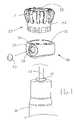
- FIG. 2is a perspective view of the regulating apparatus in accordance with FIG. 1 fixed atop a hydraulic cylinder;
- FIG. 3is a perspective view of the hydraulic cylinder of FIG. 2 that is installed in a treadmill.
- FIG. 4is a perspective view of a conventional hydraulic cylinder.
- a regulating apparatus 20 in accordance with the inventionincludes a rotating knob 21 with an opening 22 formed at a top end thereof and with a neck 23 formed at a bottom end thereof.
- the periphery of the neck 23is marked with a plurality of numbers or with colors from light to dark.
- An annular base 30includes a ring-shaped gap 31 for dividing the annular base 30 into an internal side 32 and an external side 33 .
- the external side 33has a viewing window 34 extending to the ring-shaped gap 31 .
- a magnifying glass 35is received within the viewing window 34 .
- the internal side 32 of the annular base 30is fixed on the top of the hydraulic cylinder 10 .
- the annular base 30 and the hydraulic cylinder 10are tightly joined together in a body by sticking, gluing, hot-melting, etc.
- the rotating knob 21is fixed on the annular base 30 in such a manner that an adjusting post 12 just projects from the opening 22 of the regulating knob 20 and the neck 23 is inserted into the ring-shaped gap 31 . Therefore, the number or the color disposed on the neck 23 and magnified by the magnifying glass 35 is readable from the viewing window 34 . In this way, the cushioning force of the platform of a treadmill can be adjusted to a desired value by the regulating apparatus 20 .
- a conventional treadmill A with supporting frames B, an electric control console C and handlesis shown.
- the height of the platform E and the rotational speed of an endless belt Fis adjustable.
- a cushioning seat His provided at both sides of a base frame G, respectively.
- the hydraulic cylinder 10 with the regulating apparatus 20 of the inventioncan be installed in the cushioning seat H for providing a cushioning action on the platform E. This enables a protection of operator's feet from injuries by lowering the reactive force of the platform.
- the inventionhas following advantages:
Landscapes
- Health & Medical Sciences (AREA)
- Cardiology (AREA)
- Vascular Medicine (AREA)
- General Health & Medical Sciences (AREA)
- Physical Education & Sports Medicine (AREA)
- Engineering & Computer Science (AREA)
- Mechanical Engineering (AREA)
- Rehabilitation Tools (AREA)
Abstract
Description
1. Fields of the Invention
The invention relates to an apparatus for regulating the cushioning effect to a walking platform of a treadmill, and more particularly, to a regulating apparatus with which the cushioning level can be visually identified.
2. Description of the Related Art
Treadmill is an exercise device consisting of an endless belt on which a person can walk or jog without changing place. During the exercise session, the feet of the operator will receive reactive force created by a walking platform of the treadmill when they tread thereon.
In order to reduce exercise injuries, a hydraulic cylinder is commonly employed to cushion the reactive force. Since every operator has his own body weight, the reactive force to be cushioned is different. Therefore, to install an adjustable hydraulic cylinder is an optimal solution to overcome the aforementioned problem.
A conventionalhydraulic cylinder 10, as shown inFIG. 4 , has anlower ear 11 and an adjustingpost 12 at a bottom and top end thereof, respectively. Acylinder shaft 13 is extended from the adjustingpost 12. Anupper ear 14 is formed at a free end of thecylinder shaft 13. Moreover, aknob 15 with an opening16 atop in the middle thereof is provided. Theknob 15 with its opening can be tightly fixed on the adjustingpost 12. Meanwhile, a scale is fitted around the top of thehydraulic cylinder 10, and theknob 15 has an arrow-shaped protrusion for indicating a certain cushioning strength of thehydraulic cylinder 10.
However, the scale and the arrow can become invisible due to impurities stuck thereto or due to wearing action thereon, thereby resulting in much inconvenience in use.
It is a primary object of the invention is to provide a regulating apparatus for a hydraulic cylinder of a treadmill with which the cushioning level can be visually identified.
Another object of the invention is to provide a regulating apparatus for a hydraulic cylinder of a treadmill that includes a magnifying glass disposed within the viewing window for magnifying the numbers marked on the neck of the rotating knob and, therefore, for facilitating the reading of the numbers.
The accomplishment of this and other objects of the invention will become apparent from the following description and its accompanying drawings of which:
Referring toFIG. 1 , a regulatingapparatus 20 in accordance with the invention includes a rotatingknob 21 with anopening 22 formed at a top end thereof and with aneck 23 formed at a bottom end thereof. The periphery of theneck 23 is marked with a plurality of numbers or with colors from light to dark. Anannular base 30 includes a ring-shaped gap 31 for dividing theannular base 30 into aninternal side 32 and anexternal side 33. Theexternal side 33 has aviewing window 34 extending to the ring-shaped gap 31. Amagnifying glass 35 is received within theviewing window 34.
In assembly, theinternal side 32 of theannular base 30 is fixed on the top of thehydraulic cylinder 10. Theannular base 30 and thehydraulic cylinder 10 are tightly joined together in a body by sticking, gluing, hot-melting, etc. Thereafter, therotating knob 21 is fixed on theannular base 30 in such a manner that an adjustingpost 12 just projects from the opening22 of the regulatingknob 20 and theneck 23 is inserted into the ring-shaped gap 31. Therefore, the number or the color disposed on theneck 23 and magnified by themagnifying glass 35 is readable from theviewing window 34. In this way, the cushioning force of the platform of a treadmill can be adjusted to a desired value by the regulatingapparatus 20.
Referring toFIG. 3 , a conventional treadmill A with supporting frames B, an electric control console C and handles is shown. The height of the platform E and the rotational speed of an endless belt F is adjustable. Moreover, a cushioning seat H is provided at both sides of a base frame G, respectively. Thehydraulic cylinder 10 with the regulatingapparatus 20 of the invention can be installed in the cushioning seat H for providing a cushioning action on the platform E. This enables a protection of operator's feet from injuries by lowering the reactive force of the platform.
Based on the above-mentioned, the invention has following advantages:
- 1. The cushioning strength is easily identified by sight.
- 2. The value of the cushioning strength can be magnified for an easy identification.
Many changes and modifications in the above-described embodiment of the invention can, of course, be carried out without departing from the scope thereof. Accordingly, to promote the progress in science and the useful arts, the invention is disclosed and is intended to be limited only by the scope of the appended claims.
Claims (2)
1. A regulating apparatus for a hydraulic cylinder of a treadmill comprising:
a) a rotating knob with an opening formed on a top portion thereof and with a neck formed at a bottom end thereof, the periphery of the neck being marked with a plurality of numbers or with colors from light to dark; and
b) an annular base having a ring-shaped gap for dividing the annular base into an internal side and an external side, the external side having a viewing window extending to the ring-shaped gap, a glass being received within the viewing window, the internal side of the annular base can be fixed on a top end of a hydraulic cylinder, the hydraulic cylinder having an adjusting post that projects through the opening of the rotating knob while the neck of the rotating knob is inserted into the ring-shaped gap;
whereby the numbers or the colors disposed on the neck are visible from the viewing window when the adjusting post is rotated with the rotating knob for adjusting the hydraulic cylinder's cushioning force.
2. The regulating apparatus for a hydraulic cylinder of a treadmill ofclaim 1 wherein the glass disposed within the viewing window is a magnifying glass for magnifying the numbers or colors marked on the neck of the rotating knob and, therefore, for facilitating the reading of the numbers or colors.
Priority Applications (1)
| Application Number | Priority Date | Filing Date | Title |
|---|---|---|---|
| US10/843,470US7252624B2 (en) | 2004-05-12 | 2004-05-12 | Regulating apparatus for a hydraulic cylinder of a treadmill |
Applications Claiming Priority (1)
| Application Number | Priority Date | Filing Date | Title |
|---|---|---|---|
| US10/843,470US7252624B2 (en) | 2004-05-12 | 2004-05-12 | Regulating apparatus for a hydraulic cylinder of a treadmill |
Publications (2)
| Publication Number | Publication Date |
|---|---|
| US20050255970A1 US20050255970A1 (en) | 2005-11-17 |
| US7252624B2true US7252624B2 (en) | 2007-08-07 |
Family
ID=35310133
Family Applications (1)
| Application Number | Title | Priority Date | Filing Date |
|---|---|---|---|
| US10/843,470Expired - Fee RelatedUS7252624B2 (en) | 2004-05-12 | 2004-05-12 | Regulating apparatus for a hydraulic cylinder of a treadmill |
Country Status (1)
| Country | Link |
|---|---|
| US (1) | US7252624B2 (en) |
Cited By (14)
| Publication number | Priority date | Publication date | Assignee | Title |
|---|---|---|---|---|
| US20100059964A1 (en)* | 2008-09-05 | 2010-03-11 | Sram Corporation | Bicycle Suspension System |
| ITTO20111174A1 (en)* | 2011-12-19 | 2013-06-20 | Indesit Co Spa | SELECTION INTERFACE FOR THE CONTROL OF HOME APPLIANCES |
| US10625114B2 (en) | 2016-11-01 | 2020-04-21 | Icon Health & Fitness, Inc. | Elliptical and stationary bicycle apparatus including row functionality |
| US10864406B2 (en) | 2016-08-27 | 2020-12-15 | Peloton Interactive, Inc. | Exercise system and method |
| US10898760B2 (en) | 2017-12-14 | 2021-01-26 | Peloton Interactive, Inc. | Coordinating workouts across remote exercise machines |
| US10974094B2 (en) | 2016-08-27 | 2021-04-13 | Peloton Interactive, Inc. | Exercise system and method |
| US11081224B2 (en) | 2012-07-31 | 2021-08-03 | Peloton Interactive, Inc. | Exercise system and method |
| US11219799B2 (en) | 2016-08-27 | 2022-01-11 | Peloton Interactive, Inc. | Exercise system and method |
| US11298591B2 (en) | 2016-08-27 | 2022-04-12 | Peloton Interactive, Inc. | Exercise machine controls |
| US11311791B2 (en) | 2016-08-27 | 2022-04-26 | Peloton Interactive, Inc. | Exercise system and method |
| US11338190B2 (en) | 2017-11-12 | 2022-05-24 | Peloton Interactive, Inc. | User interface with segmented timeline |
| US11610664B2 (en) | 2012-07-31 | 2023-03-21 | Peloton Interactive, Inc. | Exercise system and method |
| US12214260B2 (en) | 2016-08-27 | 2025-02-04 | Peloton Interactive, Inc. | Exercise machine controls |
| USD1087109S1 (en) | 2017-11-12 | 2025-08-05 | Peloton Interactive, Inc. | Display screen or portion thereof with a graphical user interface |
Families Citing this family (4)
| Publication number | Priority date | Publication date | Assignee | Title |
|---|---|---|---|---|
| US20090124466A1 (en)* | 2007-11-09 | 2009-05-14 | Johnson Health Tech Co., Ltd. | Treadmill having a compact shape |
| US10493349B2 (en) | 2016-03-18 | 2019-12-03 | Icon Health & Fitness, Inc. | Display on exercise device |
| US10625137B2 (en) | 2016-03-18 | 2020-04-21 | Icon Health & Fitness, Inc. | Coordinated displays in an exercise device |
| USD854101S1 (en)* | 2018-01-05 | 2019-07-16 | Peloton Interactive, Inc. | Treadmill |
Citations (13)
| Publication number | Priority date | Publication date | Assignee | Title |
|---|---|---|---|---|
| US3077179A (en)* | 1961-08-22 | 1963-02-12 | Evanson Emil | Position indicator for elongatable actuators such as hydraulic cylinders |
| US4198921A (en)* | 1978-02-15 | 1980-04-22 | Sparex Ltd. of Exeter Airport | Fluid pressure actuators indicator |
| US4478412A (en)* | 1982-05-26 | 1984-10-23 | Muir Arthur M | Exercise device and control valve therefor |
| US4705271A (en)* | 1984-12-21 | 1987-11-10 | Applied Power Inc. | Exercise apparatus |
| US5071115A (en)* | 1990-11-19 | 1991-12-10 | Welch Robert M | Exercise device for simulating walking and stair climbing |
| US5190505A (en)* | 1989-11-06 | 1993-03-02 | Proform Fitness Products, Inc. | Stepper exerciser |
| US5336146A (en)* | 1993-12-15 | 1994-08-09 | Piaget Gary D | Treadmill with dual reciprocating treads |
| US5762587A (en)* | 1995-02-01 | 1998-06-09 | Icon Health & Fitness, Inc. | Exercise machine with adjustable-resistance, hydraulic cylinder |
| US5799758A (en)* | 1996-08-20 | 1998-09-01 | Huang; Chen-Tan | Double-acting hydraulic cylinder for use in an exercising apparatus |
| US6044940A (en)* | 1996-11-13 | 2000-04-04 | Marzocchi S.P.A. | Remote-controlled hydropneumatic shock absorber |
| US6317922B1 (en)* | 1999-08-13 | 2001-11-20 | Truth Hardware Corporation | Door closer |
| US20040192512A1 (en)* | 2003-03-27 | 2004-09-30 | Kuo Hai Pin | Dual treadmill having adjustable resistance |
| US6953419B2 (en)* | 2003-04-11 | 2005-10-11 | Leao Wang | Displacement detector of a platform for an exercise apparatus |
- 2004
- 2004-05-12USUS10/843,470patent/US7252624B2/ennot_activeExpired - Fee Related
Patent Citations (13)
| Publication number | Priority date | Publication date | Assignee | Title |
|---|---|---|---|---|
| US3077179A (en)* | 1961-08-22 | 1963-02-12 | Evanson Emil | Position indicator for elongatable actuators such as hydraulic cylinders |
| US4198921A (en)* | 1978-02-15 | 1980-04-22 | Sparex Ltd. of Exeter Airport | Fluid pressure actuators indicator |
| US4478412A (en)* | 1982-05-26 | 1984-10-23 | Muir Arthur M | Exercise device and control valve therefor |
| US4705271A (en)* | 1984-12-21 | 1987-11-10 | Applied Power Inc. | Exercise apparatus |
| US5190505A (en)* | 1989-11-06 | 1993-03-02 | Proform Fitness Products, Inc. | Stepper exerciser |
| US5071115A (en)* | 1990-11-19 | 1991-12-10 | Welch Robert M | Exercise device for simulating walking and stair climbing |
| US5336146A (en)* | 1993-12-15 | 1994-08-09 | Piaget Gary D | Treadmill with dual reciprocating treads |
| US5762587A (en)* | 1995-02-01 | 1998-06-09 | Icon Health & Fitness, Inc. | Exercise machine with adjustable-resistance, hydraulic cylinder |
| US5799758A (en)* | 1996-08-20 | 1998-09-01 | Huang; Chen-Tan | Double-acting hydraulic cylinder for use in an exercising apparatus |
| US6044940A (en)* | 1996-11-13 | 2000-04-04 | Marzocchi S.P.A. | Remote-controlled hydropneumatic shock absorber |
| US6317922B1 (en)* | 1999-08-13 | 2001-11-20 | Truth Hardware Corporation | Door closer |
| US20040192512A1 (en)* | 2003-03-27 | 2004-09-30 | Kuo Hai Pin | Dual treadmill having adjustable resistance |
| US6953419B2 (en)* | 2003-04-11 | 2005-10-11 | Leao Wang | Displacement detector of a platform for an exercise apparatus |
Cited By (32)
| Publication number | Priority date | Publication date | Assignee | Title |
|---|---|---|---|---|
| US20100059964A1 (en)* | 2008-09-05 | 2010-03-11 | Sram Corporation | Bicycle Suspension System |
| US7988173B2 (en)* | 2008-09-05 | 2011-08-02 | Sram, Llc | Bicycle suspension system |
| ITTO20111174A1 (en)* | 2011-12-19 | 2013-06-20 | Indesit Co Spa | SELECTION INTERFACE FOR THE CONTROL OF HOME APPLIANCES |
| US11295849B2 (en) | 2012-07-31 | 2022-04-05 | Peloton Interactive, Inc. | Exercise system and method |
| US11915817B2 (en) | 2012-07-31 | 2024-02-27 | Peloton Interactive, Inc. | Exercise system and method |
| US12249413B2 (en) | 2012-07-31 | 2025-03-11 | Peloton Interactive, Inc. | Exercise system and method |
| US11640856B2 (en) | 2012-07-31 | 2023-05-02 | Peloton Interactive, Inc. | Exercise system and method |
| US11081224B2 (en) | 2012-07-31 | 2021-08-03 | Peloton Interactive, Inc. | Exercise system and method |
| US11139061B2 (en) | 2012-07-31 | 2021-10-05 | Peloton Interactive, Inc. | Exercise system and method |
| US11145399B2 (en) | 2012-07-31 | 2021-10-12 | Peleton Interactive, Inc. | Exercise system and method |
| US11145398B2 (en) | 2012-07-31 | 2021-10-12 | Peloton Interactive, Inc. | Exercise system and method |
| US11170886B2 (en) | 2012-07-31 | 2021-11-09 | Peloton Interactive, Inc. | Exercise system and method |
| US11183288B2 (en) | 2012-07-31 | 2021-11-23 | Peloton Interactive, Inc. | Exercise system and method |
| US11610664B2 (en) | 2012-07-31 | 2023-03-21 | Peloton Interactive, Inc. | Exercise system and method |
| US11289185B2 (en) | 2012-07-31 | 2022-03-29 | Peloton Interactive, Inc. | Exercise system and method |
| US11295850B2 (en) | 2012-07-31 | 2022-04-05 | Peloton Interactive, Inc. | Exercise system and method |
| USD995554S1 (en) | 2016-08-27 | 2023-08-15 | Peloton Interactive, Inc. | Display screen or portion thereof with graphical user interface |
| US10974094B2 (en) | 2016-08-27 | 2021-04-13 | Peloton Interactive, Inc. | Exercise system and method |
| US11617921B2 (en) | 2016-08-27 | 2023-04-04 | Peloton Interactive, Inc. | Exercise machine controls |
| US11298591B2 (en) | 2016-08-27 | 2022-04-12 | Peloton Interactive, Inc. | Exercise machine controls |
| US11400344B2 (en) | 2016-08-27 | 2022-08-02 | Peloton Interactive, Inc. | Exercise system and method |
| US11219799B2 (en) | 2016-08-27 | 2022-01-11 | Peloton Interactive, Inc. | Exercise system and method |
| US10864406B2 (en) | 2016-08-27 | 2020-12-15 | Peloton Interactive, Inc. | Exercise system and method |
| US11311791B2 (en) | 2016-08-27 | 2022-04-26 | Peloton Interactive, Inc. | Exercise system and method |
| US12350552B2 (en) | 2016-08-27 | 2025-07-08 | Peloton Interactive, Inc. | Exercise system and method |
| US12343595B2 (en) | 2016-08-27 | 2025-07-01 | Peloton Interactive, Inc. | Exercise system and method |
| US12214260B2 (en) | 2016-08-27 | 2025-02-04 | Peloton Interactive, Inc. | Exercise machine controls |
| US12280293B2 (en) | 2016-08-27 | 2025-04-22 | Peloton Interactive, Inc. | Exercise system and method |
| US10625114B2 (en) | 2016-11-01 | 2020-04-21 | Icon Health & Fitness, Inc. | Elliptical and stationary bicycle apparatus including row functionality |
| US11338190B2 (en) | 2017-11-12 | 2022-05-24 | Peloton Interactive, Inc. | User interface with segmented timeline |
| USD1087109S1 (en) | 2017-11-12 | 2025-08-05 | Peloton Interactive, Inc. | Display screen or portion thereof with a graphical user interface |
| US10898760B2 (en) | 2017-12-14 | 2021-01-26 | Peloton Interactive, Inc. | Coordinating workouts across remote exercise machines |
Also Published As
| Publication number | Publication date |
|---|---|
| US20050255970A1 (en) | 2005-11-17 |
Similar Documents
| Publication | Publication Date | Title |
|---|---|---|
| US7252624B2 (en) | Regulating apparatus for a hydraulic cylinder of a treadmill | |
| US6527678B1 (en) | Electric treadmill to whose console the weight of the operator is automatically sent | |
| US6702726B2 (en) | Compliant body-pressing exerciser | |
| US20230356024A1 (en) | Seated treadmill and method of use | |
| CN107205503B (en) | Sports belt with removable modules | |
| AU2021203663B2 (en) | Seated treadmill and method of use | |
| US5205798A (en) | Sporting and exercising unit | |
| US7094183B2 (en) | Multi-purpose surfing balancer | |
| US7618358B2 (en) | Training device | |
| US20130017937A1 (en) | Training device for balance, agility and proprioception exercises | |
| US20040142801A1 (en) | Compliant body-pressing exerciser | |
| JP2003169822A (en) | Goggles for sports | |
| CN105920780A (en) | Rotational Resistance System | |
| US20110281701A1 (en) | Twister with combination pivotal and vertical movements | |
| US20200222750A1 (en) | Gait training device | |
| US20060010587A1 (en) | Swimming goggle | |
| US7175567B2 (en) | Gymnastics springboard with adjustable elasticity designed for training and competition | |
| WO2004062401A3 (en) | Protective eyewear device for sports | |
| US9061179B2 (en) | Customizable eyewear | |
| KR102146074B1 (en) | Trampoline System for Jump Fitness | |
| CA3112911A1 (en) | Safety helmet lighting device | |
| KR101801918B1 (en) | Apparatus for improving core atheletic ability | |
| US20070135268A1 (en) | Treadle assembly of an exercise equipment | |
| US7407465B1 (en) | Torso exercising apparatus | |
| US20200346067A1 (en) | Exercise Placement Mat |
Legal Events
| Date | Code | Title | Description |
|---|---|---|---|
| REMI | Maintenance fee reminder mailed | ||
| LAPS | Lapse for failure to pay maintenance fees | ||
| STCH | Information on status: patent discontinuation | Free format text:PATENT EXPIRED DUE TO NONPAYMENT OF MAINTENANCE FEES UNDER 37 CFR 1.362 | |
| FP | Expired due to failure to pay maintenance fee | Effective date:20110807 |