US7252394B1 - Laser projection display and illumination device with MEMS scanning mirror for indoor and outdoor applications - Google Patents
Laser projection display and illumination device with MEMS scanning mirror for indoor and outdoor applicationsDownload PDFInfo
- Publication number
- US7252394B1 US7252394B1US10/723,400US72340004AUS7252394B1US 7252394 B1US7252394 B1US 7252394B1US 72340004 AUS72340004 AUS 72340004AUS 7252394 B1US7252394 B1US 7252394B1
- Authority
- US
- United States
- Prior art keywords
- image
- solid state
- light source
- light beam
- mems
- Prior art date
- Legal status (The legal status is an assumption and is not a legal conclusion. Google has not performed a legal analysis and makes no representation as to the accuracy of the status listed.)
- Expired - Lifetime, expires
Links
Images


Classifications
- G—PHYSICS
- G03—PHOTOGRAPHY; CINEMATOGRAPHY; ANALOGOUS TECHNIQUES USING WAVES OTHER THAN OPTICAL WAVES; ELECTROGRAPHY; HOLOGRAPHY
- G03B—APPARATUS OR ARRANGEMENTS FOR TAKING PHOTOGRAPHS OR FOR PROJECTING OR VIEWING THEM; APPARATUS OR ARRANGEMENTS EMPLOYING ANALOGOUS TECHNIQUES USING WAVES OTHER THAN OPTICAL WAVES; ACCESSORIES THEREFOR
- G03B21/00—Projectors or projection-type viewers; Accessories therefor
- G03B21/14—Details
- G03B21/28—Reflectors in projection beam
- H—ELECTRICITY
- H04—ELECTRIC COMMUNICATION TECHNIQUE
- H04N—PICTORIAL COMMUNICATION, e.g. TELEVISION
- H04N9/00—Details of colour television systems
- H04N9/12—Picture reproducers
- H04N9/31—Projection devices for colour picture display, e.g. using electronic spatial light modulators [ESLM]
- H04N9/3129—Projection devices for colour picture display, e.g. using electronic spatial light modulators [ESLM] scanning a light beam on the display screen
- G—PHYSICS
- G02—OPTICS
- G02B—OPTICAL ELEMENTS, SYSTEMS OR APPARATUS
- G02B26/00—Optical devices or arrangements for the control of light using movable or deformable optical elements
- G02B26/08—Optical devices or arrangements for the control of light using movable or deformable optical elements for controlling the direction of light
- G02B26/10—Scanning systems
- G02B26/101—Scanning systems with both horizontal and vertical deflecting means, e.g. raster or XY scanners
- Y—GENERAL TAGGING OF NEW TECHNOLOGICAL DEVELOPMENTS; GENERAL TAGGING OF CROSS-SECTIONAL TECHNOLOGIES SPANNING OVER SEVERAL SECTIONS OF THE IPC; TECHNICAL SUBJECTS COVERED BY FORMER USPC CROSS-REFERENCE ART COLLECTIONS [XRACs] AND DIGESTS
- Y10—TECHNICAL SUBJECTS COVERED BY FORMER USPC
- Y10S—TECHNICAL SUBJECTS COVERED BY FORMER USPC CROSS-REFERENCE ART COLLECTIONS [XRACs] AND DIGESTS
- Y10S362/00—Illumination
- Y10S362/812—Signs
Definitions
- the inventionrelates to an image projection apparatus employing micro-electro-mechanical system (MEMS) scanning mirrors and laser light sources.
- MEMSmicro-electro-mechanical system
- Various display systemshave been developed for illuminating graphics for indoor and outdoor advertisement and entertainment. Some examples of these display systems include illuminated billboards, light-emitting diode (LED) displays, neon light signs, and liquid crystal flat-panels. These display systems typically consume substantial electrical power and are bulky in construction. Thus, substantial efforts are spent to transport, set up, power, and maintain these display systems. In addition, some of these display systems cannot display images with sufficient brightness to be visible indoor under illumination or outdoor under daylight.
- LEDlight-emitting diode
- Image projection systems utilizing digital micromirror device (DMD), liquid crystal display (LCD) panel, and liquid crystal on silicon (LCoS) technologiesare capable of displaying high quality images indoors.
- DMDdigital micromirror device
- LCDliquid crystal display
- LCDoSliquid crystal on silicon
- These devicestypically use two types of high power bulbs, halogen and metal halide, whose lifetime is approximately in the range of 2,000 to 6,000 hours. The lifetime of these bulbs presents a challenge against the constant use of these systems to display images. On the other hand, the lifetime of solid state lasers are over 50,000 hours, an order of magnitude longer than the halogen and metal halide bulbs.
- Solid state lasersare known to produce high brightness and saturated colors with low power consumption. Lasers can be used very effectively in laser projection systems, including those for laser printers and laser light shows, where a tightly controlled beam is desirable. These conventional laser projection systems require efficient cooling because they utilize high power lasers. These systems are also inherently cumbersome and expensive because they utilize mechanical deflectors, polygonal mirror, and galvanometer mirror.
- a compact, low power projection display systemis proved to produce a bright image viewable in both indoor and outdoor environments.
- the projection display systemincludes a light source unit that generates monochrome light beams, an optical modulation unit that modulates the monochrome light beams to desired hues and tones, an optical synthesizing device that combines the monochrome light beams into one single light beam, a reflecting mirror unit for scanning the one single light beam to project a two-dimensional image, and an image processing unit that decodes a composite image signal to control signals for the optical modulation unit and the reflecting mirror unit.
- the projection display apparatus systemfurther includes a sensing unit that generates a feedback signal of the speed and the position of the reflecting mirror unit in order to maintain the synchronization of light radiation and to avoid jitter of the projected image.
- the light source unitmay be solid state including laser diodes, either edge emitting type or surface emitting type, diode pumped solid state frequency doubled (DPSSFD) laser, or high brightness light emitting diodes.
- the light source unitmay generate light beams in red, green and blue colors for creating a color image, or a single selected color for a monochrome image.
- the solid state light source unitmay emit in free space or be guided in optical fibers for easy assembly.
- the image signal processing unitmay include a decoder for extracting the vertical and horizontal synchronization signals from the composite image signal for raster scanning the image, a read/write controller for synchronizing the vertical and horizontal synchronization signals with the position and the speed of the reflecting mirror unit, and a memory for buffering the color intensity signals.
- the optical modulation unitmay include acoustic-optic modulators, magneto-optic modulators, or electro-optic modulators for independently modulating the red, green and blue beams generated by the light source unit.
- the optical modulation unitmay be an electrical circuitry controlled by the read/write controller that directly modulates the timing, duration, and intensity of electrical driving pulses of the light source unit.
- the optical synthesizing devicemay include optical elements such as dichroic mirrors and optical lenses.
- the reflecting mirror unitmay be one or two MEMS scanning mirrors that raster scan the one single light beam horizontally and vertically to form the desired image by oscillating at desired frequencies.
- the horizontal and vertical scanning frequency of the mirrorshave to be at least 23 kHz and 60 Hz, respectively.
- the MEMS mirroris capable of scanning both horizontally and vertically.
- one MEMS mirroris responsible for the horizontal scan and the other is responsible for the vertical scan.
- the projected imageis comprised of multiple image tiles generated by multiple light source units reflecting from one reflecting mirror unit.
- the multiple light source unitsare oriented such that the resulting image tiles form a seamless image with substantially higher resolution than the resolution achievable by a single light source unit.
- the projection display systemincludes a translucent screen as the projection plane and all the components are enclosed in a casing to form a rear projection display system.
- the projection display systemreplaces the halogen and metal halide light bulbs of conventional projection display apparatuses employing liquid crystal display (LCD) panel, liquid crystal on silicon (LCoS) device, and digital micromirror display (DMD) device.
- LCDliquid crystal display
- LCDoSliquid crystal on silicon
- DMDdigital micromirror display
- the projection display systemincludes a light source unit and a scanning mirror system to project or illuminate a preexisting image.
- the imagecan be an advertisement located on a wall, a screen, a sign, or a billboard.
- the imagecan also be located on a semi-transparent medium and be projected onto a medium to produce a larger image.
- FIG. 1is a block diagram of a laser projection display system in one embodiment of the invention.
- FIG. 1Ais a block diagram of an image processing unit in the system of FIG. 1 in one embodiment of the invention.
- FIG. 2is a block diagram of a laser projection display system in another embodiment of the invention.
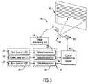
- FIG. 3illustrates an optical sensing unit for detecting the speed and position of the scanning mirror in one embodiment of the invention.
- FIG. 4illustrates an optical sensing unit comprising a light source and an optical detector for detecting the speed and position of the horizontal scanning mirror in one embodiment of the invention.
- FIG. 5illustrates a laser projection display system projecting an image consisting of image tiles generated by multiple light source units and a common reflecting mirror unit in one embodiment of the invention.
- FIG. 6illustrates a laser projection display system in a casing including a translucent screen and a plurality of diffusers and lenses in one embodiment of the invention.
- FIG. 7is a block diagram of a system where a laser projection display system is the light source for a light valve device such as a digital micromirror device (DMD), a liquid crystal on silicon (LCoS) display, or a liquid crystal display (LCD) in one embodiment of the invention.
- a light valve devicesuch as a digital micromirror device (DMD), a liquid crystal on silicon (LCoS) display, or a liquid crystal display (LCD) in one embodiment of the invention.
- DMDdigital micromirror device
- LCDliquid crystal on silicon
- LCDliquid crystal display
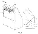
- FIG. 8illustrates a MEMS projection display where the image is projected from the same side of the viewer onto a screen in one embodiment of the invention.
- FIG. 9illustrates a MEMS projection display where the image is projected from the opposite side of the viewer onto a screen that is semi-transparent in one embodiment of the invention.
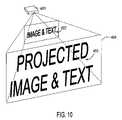
- FIG. 10illustrates a MEMS projection display that projects a semi-transparent image to create a larger image in one embodiment of the invention.
- FIG. 11illustrates a MEMS projection display that utilizes a mirror array to increase the image resolution and brightness of the projected image in one embodiment of the invention.
- FIG. 12illustrates a flash light in one embodiment of the invention.
- FIG. 1illustrates a projection display system 1 in one embodiment of the invention.
- Projection display system 1includes an image processing unit 10 , a light source unit 20 , an optical modulation unit 30 , an optical synthesizing device 40 , a scanning mirror controller unit 50 , a reflecting mirror unit 60 , and a mirror sensing unit 70 .
- FIG. 1Aillustrates image processing unit 10 in one embodiment.
- Image processing unit 10includes (1) a decoder 11 for dividing a composite image signal into a composite synchronous signal, a red signal, a green signal, and a blue signal, (2) a signal separator 12 for separating the composite synchronous signal into a horizontal synchronization signal and a vertical synchronization signal, (3) a read/write controller 13 for controlling the light source unit 20 and synchronizing the vertical and the horizontal synchronization signals with the position and speed of reflecting mirror unit 60 , and (4) a memory 14 for buffering the red, green, and blue signals.
- a decoder 11for dividing a composite image signal into a composite synchronous signal, a red signal, a green signal, and a blue signal
- a signal separator 12for separating the composite synchronous signal into a horizontal synchronization signal and a vertical synchronization signal
- a read/write controller 13for controlling the light source unit 20 and synchronizing the vertical and the horizontal synchronization signals with the position
- light source unit 20emits red, green, and blue monochrome light beams.
- the monochrome light beamscan travel in air or in optical fibers to optical modulation unit 30 .
- Optical modulation unit 30modulates the red, the green, and the blue monochrome light beams to achieve the desired hues and tones in response to the color intensity signals received from image processing unit 10 .
- Optical synthesizing device 40combines the light beams into one single light path before striking reflecting mirror unit 60 .
- the combined light beamcan travel in air or in an optical fiber to reflecting mirror unit 60 .
- Reflecting mirror unit 60which is capable of both horizontal and vertical scans, reflects the combined light beam in a raster scan to project one or more two-dimensional image 90 ( FIG. 3 ).
- Scanning mirror controller 50drives reflecting mirror unit 60 in response to the vertical and horizontal synchronization signals received from image process unit 10 .
- FIG. 3shows that light source unit 20 includes three solid state light sources 25 , 26 , and 27 that generate the red, green, and blue monochrome light beams.
- Solid state light sources 25 , 26 , and 27may be semiconductor edge emitting laser diodes (LD), vertical cavity surface emitting laser diodes (VCSEL), diode pumped solid state frequency doubled (DPSSFD) lasers, or light emitting diodes (LED).
- LDsemiconductor edge emitting laser diodes
- VCSELvertical cavity surface emitting laser diodes
- DPSSFDdiode pumped solid state frequency doubled
- LEDlight emitting diodes
- Optical modulation unit 30includes three optical modulators 35 , 36 , and 37 respectively receiving the red, green, and blue monochrome light beams.
- Optical modulators 35 , 36 , and 37may be acoustic-optic modulators, electro-optic modulators, or magneto-optic modulators.
- optical modulation unit 30may be a set of electrical circuitry 31 controlled by read/write controller 12 ( FIG. 1A ) of image processing unit 10 .
- Optical modulator unit 30then directly modulates the timing, duration, and intensity of the electrical driving pulses of light source unit 20 to change the hues and tones of the red, green, and blue monochrome light beams.
- Reflecting mirror unit 60may be a bi-directional micro-electro-mechanical system (MEMS) scanning mirror, a first MEMS scanning mirror 61 ( FIG. 3 ) rotating about a horizontal axis and a second MEMS scanning mirror 62 ( FIG. 3 ) rotating about a vertical axis, or one or more galvanometer mirrors manufactured by mechanical processes.
- MEMSmicro-electro-mechanical system
- mirror sensing unit 70is an optical detector/transducer 71 ( FIG. 3 ) that detects the scanning speed and position of one of the monochrome light beams.
- sensing unit 70may include an optical detector 72 and a solid state light source 73 .
- Sensing unit 70determines the horizontal scanning motion by detecting the light beam emitting from light source 73 and reflected by horizontal scanning mirror 61 .
- sensing unit 70may include an optical detector 74 and another solid state light source 75 .
- Sensing unit 70determines the vertical scanning motion by detecting the light beam emitting from light source 75 and reflected by vertical scanning mirror 62 .
- sensing unit 70is a capacitance sensor embedded in a scanning mirror to detect a change in capacitance from the movement of reflecting mirror unit 60 .
- sensing unit 70is a piezoelectric sensor embedded in a scanning mirror to detect a change in current from the movement of reflecting mirror unit 60 .
- FIG. 5shows a projection display system 80 in one embodiment of the invention.
- Projection display system 80projects an image that consists of multiple image tiles 81 , 82 , 83 , and 84 generated by a plurality of light source units 21 , 22 , 23 and 24 reflecting from a common reflecting mirror unit 60 .
- Reflecting mirror unit 60includes a common vertical scanning mirror 62 that receives light reflected from two horizontal scanning mirrors 61 and 63 .
- Light sources 21 , 22 , 23 , and 24transmit their respective light beams through optical fibers 21 A, 22 A, 23 A, and 24 A, which are oriented so resulting image tiles 81 , 82 , 83 , and 84 form a seamless unified image with substantially higher resolution than the resolution achievable by a single light source unit.
- the optical fibersallow easy alignment and assembly of projection display system 80 .
- FIG. 6shows a projection television 100 in one embodiment of the invention.
- Projection television 100includes a translucent screen 102 and a plurality of lenses 103 and diffusers 104 all located in a casing 105 .
- Lenses 103 and diffusers 104expand the projected images from projection display system 1 to form an enlarge image 106 on translucent screen 102 for viewing.
- Digital projectors that employ DMD, LCD, and LCoS technologiesuse either halogen or metal halide bulbs as their light source. These bulbs have a short lifetime of less than 6,000 hours.
- Conventional laser projection systemsutilize high power lasers and mechanical deflectors, polygonal mirror, and galvanometer mirror. They consume a large amount of electrical power and generate a substantial amount of heat. The conventional laser projection system also may require special cooling. Furthermore, they are inherently cumbersome and expensive.
- FIG. 7shows a block diagram block diagram of a projection illumination system 200 that may be used as the light source for a digital projector 201 employing a light-valve device 291 such as digital micromirror device (DMD), liquid crystal display (LCD), or liquid crystal on silicon (LCoS) display.
- System 200includes a signal processing unit 210 , a light source unit 20 , an optical synthesizing device 230 , a scanning mirror controller unit 50 , and a reflecting mirror unit 60 .
- the red, green and blue monochrome light beams emitting from light source unit 20is combined by optical synthesizing device 230 into a white light beam and projected onto reflecting mirror unit 60 .
- Reflecting mirror unit 60scans the white light beam horizontally and vertically to illuminate a two-dimensional area over optics 290 of digital projector 201 .
- Optics 290then directs the light beam onto light-valve device 291 .
- Light-valve device 291then modulates the light beam to project a desired image.
- FIG. 8illustrates a MEMS projection illumination system 301 in one embodiment of the invention.
- System 301includes a MEMS scanning light source that illuminates an image 302 on a medium 303 .
- the MEMS scanning light sourceincludes a plurality of solid state lasers emitting monochrome red, green and blue light beams that are modulated and synthesized into a single light path in desired color.
- the single light pathis raster scanned by MEMS scanning mirrors (e.g., a reflecting mirror system) onto medium 303 .
- the scanned light beamreflects off image 302 , which becomes visible to passersby.
- the systemis able to raster scan the entire medium 303 within the refresh rate of the human eyes so image 302 appears uniformly lighted.
- Image 302can be any form of advertisement including text.
- Medium 303can be a wall, a screen, a sign, or a billboard.
- FIG. 9illustrates MEMS projection illumination system 301 in another embodiment of the invention.
- System 301includes a MEMS scanning light source that raster scans a light beam over an image 311 .
- Image 311is on a semi-transparent material 312 so the image is visible on both sides. Thus, image 311 is visible to a passerby on the opposite side of the system 301 .
- Image 311can be part of a screen, a sign, or a billboard.
- FIG. 10illustrates a MEMS projection illumination system 401 in one embodiment of the invention.
- System 401includes a MEMS scanning light source that raster scans a light beam over a semi-transparent image 402 to project a larger image 403 onto a medium 404 .
- MEMS projection illumination system 401can replace the traditional light bulb in overhead projectors, slide machines, and LCD projectors to provide better performance and reliability, and lower power consumption.
- FIG. 11illustrates a MEMS projection illumination system 501 in one embodiment of the invention.
- System 501includes multiple MEMS scanning light sources 511 that are used to illuminate their respective portion of an image. Thus, system 501 is able to provide better illumination and higher resolution.
- FIG. 12illustrates a flash light 610 in one embodiment of the invention.
- Flash light 610includes a solid state light source 611 and a MEMS scanning mirror 612 . Both solid state light source 611 and MEMS scanning mirror 612 are powered by a battery 613 .
- Solid state light source 611generates a light beam that is raster scanned by MEMS scanning mirror 612 over an area 614 that is to be illuminated. In one embodiment, solid state light source 611 generates an infrared light to illuminate area 614 at night. Light reflected from area 614 are then detected by an infrared detector.
Landscapes
- Physics & Mathematics (AREA)
- General Physics & Mathematics (AREA)
- Optics & Photonics (AREA)
- Engineering & Computer Science (AREA)
- Multimedia (AREA)
- Signal Processing (AREA)
- Mechanical Optical Scanning Systems (AREA)
Abstract
Description
Claims (13)
Priority Applications (1)
| Application Number | Priority Date | Filing Date | Title |
|---|---|---|---|
| US10/723,400US7252394B1 (en) | 2003-07-03 | 2004-03-10 | Laser projection display and illumination device with MEMS scanning mirror for indoor and outdoor applications |
Applications Claiming Priority (2)
| Application Number | Priority Date | Filing Date | Title |
|---|---|---|---|
| US61339703A | 2003-07-03 | 2003-07-03 | |
| US10/723,400US7252394B1 (en) | 2003-07-03 | 2004-03-10 | Laser projection display and illumination device with MEMS scanning mirror for indoor and outdoor applications |
Related Parent Applications (1)
| Application Number | Title | Priority Date | Filing Date |
|---|---|---|---|
| US61339703AContinuation | 2003-07-03 | 2003-07-03 |
Publications (1)
| Publication Number | Publication Date |
|---|---|
| US7252394B1true US7252394B1 (en) | 2007-08-07 |
Family
ID=38324269
Family Applications (1)
| Application Number | Title | Priority Date | Filing Date |
|---|---|---|---|
| US10/723,400Expired - LifetimeUS7252394B1 (en) | 2003-07-03 | 2004-03-10 | Laser projection display and illumination device with MEMS scanning mirror for indoor and outdoor applications |
Country Status (1)
| Country | Link |
|---|---|
| US (1) | US7252394B1 (en) |
Cited By (59)
| Publication number | Priority date | Publication date | Assignee | Title |
|---|---|---|---|---|
| US20060066540A1 (en)* | 2004-09-27 | 2006-03-30 | Texas Instruments Incorporated | Spatial light modulation display system |
| US20060139236A1 (en)* | 2004-12-24 | 2006-06-29 | Fuji Photo Film Co. Ltd | Projection type image display apparatus |
| US20070109509A1 (en)* | 2005-11-15 | 2007-05-17 | Samsung Electronics Co., Ltd. | Projector/projection type switchable display apparatus |
| US20070229668A1 (en)* | 2006-03-31 | 2007-10-04 | Duanfeng He | Display for color image projection arrangement and method |
| US20090059334A1 (en)* | 2007-08-30 | 2009-03-05 | Hon Hai Precision Industry Co., Ltd. | Projection system and portable electronic device using same |
| US20090102830A1 (en)* | 2007-10-18 | 2009-04-23 | Samsung Electro-Mechanics Co., Ltd. | Display apparatus and method for compensating beam tilt |
| US20090116091A1 (en)* | 2007-11-05 | 2009-05-07 | Scott Patrick Overmann | Scanning Mirror Based Display System and Method |
| US20090135377A1 (en)* | 2007-11-05 | 2009-05-28 | Lg Electronics Inc. | Projection display device |
| US20090141196A1 (en)* | 2007-12-03 | 2009-06-04 | Basner Charles M | Photo microprojector |
| US20090167726A1 (en)* | 2007-12-29 | 2009-07-02 | Microvision, Inc. | Input Device for a Scanned Beam Display |
| US20090262363A1 (en)* | 2008-04-01 | 2009-10-22 | Perceptron, Inc. | Contour sensor incorporating mems mirrors |
| US20100253700A1 (en)* | 2009-04-02 | 2010-10-07 | Philippe Bergeron | Real-Time 3-D Interactions Between Real And Virtual Environments |
| EP2253986A1 (en)* | 2009-05-20 | 2010-11-24 | Funai Electric Co., Ltd. | Laser Projector |
| US20110102751A1 (en)* | 2009-07-01 | 2011-05-05 | Funai Electric Co., Ltd. | Projector |
| US20110181931A1 (en)* | 2008-07-02 | 2011-07-28 | Btendo Ltd. | mems device comprising oscillations measurements means |
| US8118434B2 (en)* | 2008-06-05 | 2012-02-21 | Disney Enterprises, Inc. | Projecting an animated object and concurrently moving the object's projection area through an animation pattern |
| US8220933B1 (en) | 2008-11-03 | 2012-07-17 | National Semiconductor Corporation | Method and apparatus for data transfer using an optical link in a projector system |
| WO2012166682A3 (en)* | 2011-06-03 | 2013-04-11 | Thomson Licencing | Variable and interleaved scanning in laser projectors |
| US8520219B2 (en) | 2011-12-19 | 2013-08-27 | Perceptron, Inc. | Non-contact sensor having improved laser spot |
| US8988316B2 (en) | 2012-02-21 | 2015-03-24 | Panasonic Intellectual Property Management Co., Ltd. | Display device |
| US9001402B2 (en) | 2011-06-03 | 2015-04-07 | Thomson Licensing | Variable and serrated scanning in laser projectors |
| US9013711B2 (en) | 2008-04-01 | 2015-04-21 | Perceptron, Inc. | Contour sensor incorporating MEMS mirrors |
| US20150268731A1 (en)* | 2014-03-21 | 2015-09-24 | Dell Products L.P. | Interactive Projected Information Handling System Support Input and Output Devices |
| US9170097B2 (en) | 2008-04-01 | 2015-10-27 | Perceptron, Inc. | Hybrid system |
| US9204129B2 (en) | 2010-09-15 | 2015-12-01 | Perceptron, Inc. | Non-contact sensing system having MEMS-based light source |
| US9304599B2 (en) | 2014-03-21 | 2016-04-05 | Dell Products L.P. | Gesture controlled adaptive projected information handling system input and output devices |
| US20160100810A1 (en)* | 2004-08-02 | 2016-04-14 | Searete Llc | Medical Overlay Mirror |
| US9348420B2 (en) | 2014-03-21 | 2016-05-24 | Dell Products L.P. | Adaptive projected information handling system output devices |
| US9547162B2 (en) | 2015-02-25 | 2017-01-17 | The Regents Of The University Of Michigan | Interactive projection system |
| EP3163353A1 (en)* | 2015-10-28 | 2017-05-03 | Stanley Electric Co., Ltd. | Video projection apparatus capable of realizing stable rocking angle at optimum resonant frequency |
| WO2017172016A1 (en)* | 2016-03-31 | 2017-10-05 | Intel Corporation | Optical isolator |
| US9965038B2 (en) | 2014-03-21 | 2018-05-08 | Dell Products L.P. | Context adaptable projected information handling system input environment |
| US20180292654A1 (en)* | 2017-04-07 | 2018-10-11 | Microsoft Technology Licensing, Llc | Scanner-illuminated lcos projector for head mounted display |
| US10139929B2 (en) | 2015-04-21 | 2018-11-27 | Dell Products L.P. | Information handling system interactive totems |
| US10139973B2 (en) | 2016-11-09 | 2018-11-27 | Dell Products L.P. | Information handling system totem tracking management |
| US10139951B2 (en) | 2016-11-09 | 2018-11-27 | Dell Products L.P. | Information handling system variable capacitance totem input management |
| US10139930B2 (en) | 2016-11-09 | 2018-11-27 | Dell Products L.P. | Information handling system capacitive touch totem management |
| US10146366B2 (en) | 2016-11-09 | 2018-12-04 | Dell Products L.P. | Information handling system capacitive touch totem with optical communication support |
| US20190137941A1 (en)* | 2017-11-06 | 2019-05-09 | Chia Wei HSU | Laser projection clock |
| US10317670B2 (en) | 2017-03-03 | 2019-06-11 | Microsoft Technology Licensing, Llc | MEMS scanning display device |
| CN109946909A (en)* | 2017-12-21 | 2019-06-28 | 中强光电股份有限公司 | Projection device |
| US10341627B2 (en) | 2012-06-28 | 2019-07-02 | Intermec Ip Corp. | Single-handed floating display with selectable content |
| US10365709B2 (en) | 2017-03-03 | 2019-07-30 | Microsoft Technology Licensing, Llc | MEMS scanning display device |
| US10417975B2 (en)* | 2017-04-03 | 2019-09-17 | Microsoft Technology Licensing, Llc | Wide field of view scanning display |
| US10459528B2 (en) | 2018-02-28 | 2019-10-29 | Dell Products L.P. | Information handling system enhanced gesture management, control and detection |
| EP3532881A4 (en)* | 2016-10-28 | 2019-11-13 | Magic Leap, Inc. | METHOD AND SYSTEM FOR A BROAD FIELD OF VISION DISPLAY DEVICE HAVING A SCAN REFLECTOR |
| US10499021B2 (en)* | 2017-04-11 | 2019-12-03 | Microsoft Technology Licensing, Llc | Foveated MEMS scanning display |
| US10496216B2 (en) | 2016-11-09 | 2019-12-03 | Dell Products L.P. | Information handling system capacitive touch totem with optical communication support |
| CN111077721A (en)* | 2018-10-19 | 2020-04-28 | 宁波舜宇车载光学技术有限公司 | Vehicle lamp projection device and projection method thereof |
| US10635199B2 (en) | 2018-06-28 | 2020-04-28 | Dell Products L.P. | Information handling system dynamic friction touch device for touchscreen interactions |
| US10664101B2 (en) | 2018-06-28 | 2020-05-26 | Dell Products L.P. | Information handling system touch device false touch detection and mitigation |
| US10761618B2 (en) | 2018-06-28 | 2020-09-01 | Dell Products L.P. | Information handling system touch device with automatically orienting visual display |
| US10795502B2 (en) | 2018-06-28 | 2020-10-06 | Dell Products L.P. | Information handling system touch device with adaptive haptic response |
| US10817077B2 (en) | 2018-06-28 | 2020-10-27 | Dell Products, L.P. | Information handling system touch device context aware input tracking |
| US10852853B2 (en) | 2018-06-28 | 2020-12-01 | Dell Products L.P. | Information handling system touch device with visually interactive region |
| CN112352185A (en)* | 2018-06-27 | 2021-02-09 | 微软技术许可有限责任公司 | Adjusting the resonant frequency of a scanning mirror |
| US11204587B2 (en) | 2018-11-08 | 2021-12-21 | Samsung Electronics Co., Ltd. | Holographic display apparatus |
| RU2767328C2 (en)* | 2013-11-04 | 2022-03-17 | Долби Лэборетериз Лайсенсинг Корпорейшн | Single- and multi-modulator projection systems with global brightness control |
| CN114333613A (en)* | 2021-11-24 | 2022-04-12 | 石家庄市京华电子实业有限公司 | A micro-pitch LED display module based on field sequential color technology |
Citations (19)
| Publication number | Priority date | Publication date | Assignee | Title |
|---|---|---|---|---|
| US4750045A (en)* | 1985-08-15 | 1988-06-07 | Fuji Photo Film Co., Ltd. | Light beam scanning system |
| US5450219A (en)* | 1993-11-17 | 1995-09-12 | Hughes Aircraft Company | Raster following telecentric illumination scanning system for enhancing light throughout in light valve projection systems |
| US5691535A (en)* | 1996-02-08 | 1997-11-25 | Eastman Kodak Company | Ganged laser scanning system which corrects beam alignment along a bow-tie path |
| US5835249A (en)* | 1995-03-03 | 1998-11-10 | International Business Machines Corporation | Apparatus and method for exposing a liquid crystal panel by beam scanning |
| US5845981A (en)* | 1997-12-29 | 1998-12-08 | Philips Electronics North America Corporation | Multi-color-band scrolling across single-panel light valve |
| US5971545A (en)* | 1997-06-25 | 1999-10-26 | Hewlett-Packard Company | Light source for projection display |
| US6128131A (en)* | 1997-11-13 | 2000-10-03 | Eastman Kodak Company | Scaleable tiled flat-panel projection color display |
| US6183092B1 (en)* | 1998-05-01 | 2001-02-06 | Diane Troyer | Laser projection apparatus with liquid-crystal light valves and scanning reading beam |
| US6195184B1 (en)* | 1999-06-19 | 2001-02-27 | The United States Of America As Represented By The Administrator Of The National Aeronautics And Space Administration | High-resolution large-field-of-view three-dimensional hologram display system and method thereof |
| US20020021419A1 (en) | 2000-03-21 | 2002-02-21 | Yoder Lars A. | Combination overhead projector and electronic display device |
| US20020149749A1 (en)* | 2001-04-12 | 2002-10-17 | Koninklijke Philips Electronics N.V. | Scanner phase control for a scrolling color projector |
| US6493149B2 (en)* | 2001-04-27 | 2002-12-10 | Hitachi, Ltd. | Optical unit and image display device thereof |
| US20030011751A1 (en) | 2001-07-10 | 2003-01-16 | Canon Kabushiki Kaisha | Projection display device |
| US6508554B2 (en)* | 2000-06-12 | 2003-01-21 | Matsushita Electric Industrial Co., Ltd. | Projection-type image display apparatus |
| US6511184B2 (en)* | 2000-04-05 | 2003-01-28 | Matsushita Electric Industrial Co., Ltd. | Color image display apparatus |
| US6798575B2 (en)* | 2002-04-05 | 2004-09-28 | Canon Kabushiki Kaisha | Scanning type display optical system, scanning image display apparatus, and image display system |
| US6900916B2 (en)* | 1999-03-04 | 2005-05-31 | Fuji Photo Film Co., Ltd. | Color laser display apparatus having fluorescent screen scanned with modulated ultraviolet laser light |
| US6939013B2 (en)* | 2002-10-21 | 2005-09-06 | Canon Kabushiki Kaisha | Projection type display device |
| US6972737B2 (en)* | 2001-05-28 | 2005-12-06 | Canon Kabushiki Kaisha | Image display apparatus |
- 2004
- 2004-03-10USUS10/723,400patent/US7252394B1/ennot_activeExpired - Lifetime
Patent Citations (19)
| Publication number | Priority date | Publication date | Assignee | Title |
|---|---|---|---|---|
| US4750045A (en)* | 1985-08-15 | 1988-06-07 | Fuji Photo Film Co., Ltd. | Light beam scanning system |
| US5450219A (en)* | 1993-11-17 | 1995-09-12 | Hughes Aircraft Company | Raster following telecentric illumination scanning system for enhancing light throughout in light valve projection systems |
| US5835249A (en)* | 1995-03-03 | 1998-11-10 | International Business Machines Corporation | Apparatus and method for exposing a liquid crystal panel by beam scanning |
| US5691535A (en)* | 1996-02-08 | 1997-11-25 | Eastman Kodak Company | Ganged laser scanning system which corrects beam alignment along a bow-tie path |
| US5971545A (en)* | 1997-06-25 | 1999-10-26 | Hewlett-Packard Company | Light source for projection display |
| US6128131A (en)* | 1997-11-13 | 2000-10-03 | Eastman Kodak Company | Scaleable tiled flat-panel projection color display |
| US5845981A (en)* | 1997-12-29 | 1998-12-08 | Philips Electronics North America Corporation | Multi-color-band scrolling across single-panel light valve |
| US6183092B1 (en)* | 1998-05-01 | 2001-02-06 | Diane Troyer | Laser projection apparatus with liquid-crystal light valves and scanning reading beam |
| US6900916B2 (en)* | 1999-03-04 | 2005-05-31 | Fuji Photo Film Co., Ltd. | Color laser display apparatus having fluorescent screen scanned with modulated ultraviolet laser light |
| US6195184B1 (en)* | 1999-06-19 | 2001-02-27 | The United States Of America As Represented By The Administrator Of The National Aeronautics And Space Administration | High-resolution large-field-of-view three-dimensional hologram display system and method thereof |
| US20020021419A1 (en) | 2000-03-21 | 2002-02-21 | Yoder Lars A. | Combination overhead projector and electronic display device |
| US6511184B2 (en)* | 2000-04-05 | 2003-01-28 | Matsushita Electric Industrial Co., Ltd. | Color image display apparatus |
| US6508554B2 (en)* | 2000-06-12 | 2003-01-21 | Matsushita Electric Industrial Co., Ltd. | Projection-type image display apparatus |
| US20020149749A1 (en)* | 2001-04-12 | 2002-10-17 | Koninklijke Philips Electronics N.V. | Scanner phase control for a scrolling color projector |
| US6493149B2 (en)* | 2001-04-27 | 2002-12-10 | Hitachi, Ltd. | Optical unit and image display device thereof |
| US6972737B2 (en)* | 2001-05-28 | 2005-12-06 | Canon Kabushiki Kaisha | Image display apparatus |
| US20030011751A1 (en) | 2001-07-10 | 2003-01-16 | Canon Kabushiki Kaisha | Projection display device |
| US6798575B2 (en)* | 2002-04-05 | 2004-09-28 | Canon Kabushiki Kaisha | Scanning type display optical system, scanning image display apparatus, and image display system |
| US6939013B2 (en)* | 2002-10-21 | 2005-09-06 | Canon Kabushiki Kaisha | Projection type display device |
Cited By (87)
| Publication number | Priority date | Publication date | Assignee | Title |
|---|---|---|---|---|
| US20160100810A1 (en)* | 2004-08-02 | 2016-04-14 | Searete Llc | Medical Overlay Mirror |
| US9615799B2 (en)* | 2004-08-02 | 2017-04-11 | Invention Science Fund I, Llc | Medical overlay mirror |
| US20060066540A1 (en)* | 2004-09-27 | 2006-03-30 | Texas Instruments Incorporated | Spatial light modulation display system |
| US20060139236A1 (en)* | 2004-12-24 | 2006-06-29 | Fuji Photo Film Co. Ltd | Projection type image display apparatus |
| US7679579B2 (en)* | 2004-12-24 | 2010-03-16 | Fujifilm Corporation | Projection type image display apparatus |
| US20070109509A1 (en)* | 2005-11-15 | 2007-05-17 | Samsung Electronics Co., Ltd. | Projector/projection type switchable display apparatus |
| US7717571B2 (en)* | 2005-11-15 | 2010-05-18 | Samsung Electronics Co., Ltd. | Projector/projection type switchable display apparatus |
| US20070229668A1 (en)* | 2006-03-31 | 2007-10-04 | Duanfeng He | Display for color image projection arrangement and method |
| US20110063527A1 (en)* | 2006-03-31 | 2011-03-17 | Microvision, Inc. | Arrangement for and Method of Projecting A Color Image By Switching Scan Directions In Alternate Frames |
| US7859567B2 (en)* | 2006-03-31 | 2010-12-28 | Microvision, Inc. | Arrangement for and method of projecting a color image by switching scan directions in alternate frames |
| US7986340B2 (en) | 2006-03-31 | 2011-07-26 | Microvision, Inc. | Arrangement for and method of projecting a color image by switching scan directions in alternate frames |
| US20090059334A1 (en)* | 2007-08-30 | 2009-03-05 | Hon Hai Precision Industry Co., Ltd. | Projection system and portable electronic device using same |
| US20090102830A1 (en)* | 2007-10-18 | 2009-04-23 | Samsung Electro-Mechanics Co., Ltd. | Display apparatus and method for compensating beam tilt |
| US20090116091A1 (en)* | 2007-11-05 | 2009-05-07 | Scott Patrick Overmann | Scanning Mirror Based Display System and Method |
| US20090135377A1 (en)* | 2007-11-05 | 2009-05-28 | Lg Electronics Inc. | Projection display device |
| US8493289B2 (en) | 2007-11-05 | 2013-07-23 | Texas Instruments Incorporated | Scanning mirror based display system and method |
| US8672484B2 (en)* | 2007-11-05 | 2014-03-18 | Lg Electronics Inc. | Projection display device for projecting light that has been collimated |
| US20090141196A1 (en)* | 2007-12-03 | 2009-06-04 | Basner Charles M | Photo microprojector |
| CN101911162A (en)* | 2007-12-29 | 2010-12-08 | 微视公司 | Input device for a scanned beam display |
| US20090167726A1 (en)* | 2007-12-29 | 2009-07-02 | Microvision, Inc. | Input Device for a Scanned Beam Display |
| US8519983B2 (en)* | 2007-12-29 | 2013-08-27 | Microvision, Inc. | Input device for a scanned beam display |
| US20090262363A1 (en)* | 2008-04-01 | 2009-10-22 | Perceptron, Inc. | Contour sensor incorporating mems mirrors |
| US9170097B2 (en) | 2008-04-01 | 2015-10-27 | Perceptron, Inc. | Hybrid system |
| US8014002B2 (en) | 2008-04-01 | 2011-09-06 | Perceptron, Inc. | Contour sensor incorporating MEMS mirrors |
| US9013711B2 (en) | 2008-04-01 | 2015-04-21 | Perceptron, Inc. | Contour sensor incorporating MEMS mirrors |
| US8118434B2 (en)* | 2008-06-05 | 2012-02-21 | Disney Enterprises, Inc. | Projecting an animated object and concurrently moving the object's projection area through an animation pattern |
| US20110181931A1 (en)* | 2008-07-02 | 2011-07-28 | Btendo Ltd. | mems device comprising oscillations measurements means |
| US8626468B2 (en) | 2008-07-02 | 2014-01-07 | Stmicroelectronics International N.V. | MEMS device comprising oscillations measurements means |
| US8220933B1 (en) | 2008-11-03 | 2012-07-17 | National Semiconductor Corporation | Method and apparatus for data transfer using an optical link in a projector system |
| US20100253700A1 (en)* | 2009-04-02 | 2010-10-07 | Philippe Bergeron | Real-Time 3-D Interactions Between Real And Virtual Environments |
| US8368006B2 (en) | 2009-05-20 | 2013-02-05 | Funai Electric Co., Ltd. | Driving a laser scanning section using a basic period of a pulse signal based on a period of a resonance frequency and accumulated period errors to produce a correction period quantity |
| EP2253986A1 (en)* | 2009-05-20 | 2010-11-24 | Funai Electric Co., Ltd. | Laser Projector |
| US8419195B2 (en)* | 2009-07-01 | 2013-04-16 | Funai Electric Co., Ltd. | Projector |
| US20110102751A1 (en)* | 2009-07-01 | 2011-05-05 | Funai Electric Co., Ltd. | Projector |
| US9204129B2 (en) | 2010-09-15 | 2015-12-01 | Perceptron, Inc. | Non-contact sensing system having MEMS-based light source |
| US9001402B2 (en) | 2011-06-03 | 2015-04-07 | Thomson Licensing | Variable and serrated scanning in laser projectors |
| US9007532B2 (en) | 2011-06-03 | 2015-04-14 | Thomson Licensing | Variable and interleaved scanning in laser projectors |
| WO2012166682A3 (en)* | 2011-06-03 | 2013-04-11 | Thomson Licencing | Variable and interleaved scanning in laser projectors |
| EP3713227A1 (en)* | 2011-06-03 | 2020-09-23 | Thomson Licensing | Variable and interleaved scanning in laser projectors |
| US8520219B2 (en) | 2011-12-19 | 2013-08-27 | Perceptron, Inc. | Non-contact sensor having improved laser spot |
| US8988316B2 (en) | 2012-02-21 | 2015-03-24 | Panasonic Intellectual Property Management Co., Ltd. | Display device |
| US10341627B2 (en) | 2012-06-28 | 2019-07-02 | Intermec Ip Corp. | Single-handed floating display with selectable content |
| RU2767328C2 (en)* | 2013-11-04 | 2022-03-17 | Долби Лэборетериз Лайсенсинг Корпорейшн | Single- and multi-modulator projection systems with global brightness control |
| US9348420B2 (en) | 2014-03-21 | 2016-05-24 | Dell Products L.P. | Adaptive projected information handling system output devices |
| US10228848B2 (en) | 2014-03-21 | 2019-03-12 | Zagorin Cave LLP | Gesture controlled adaptive projected information handling system input and output devices |
| US9965038B2 (en) | 2014-03-21 | 2018-05-08 | Dell Products L.P. | Context adaptable projected information handling system input environment |
| US20150268731A1 (en)* | 2014-03-21 | 2015-09-24 | Dell Products L.P. | Interactive Projected Information Handling System Support Input and Output Devices |
| US9304599B2 (en) | 2014-03-21 | 2016-04-05 | Dell Products L.P. | Gesture controlled adaptive projected information handling system input and output devices |
| US10133355B2 (en)* | 2014-03-21 | 2018-11-20 | Dell Products L.P. | Interactive projected information handling system support input and output devices |
| US9547162B2 (en) | 2015-02-25 | 2017-01-17 | The Regents Of The University Of Michigan | Interactive projection system |
| US10139929B2 (en) | 2015-04-21 | 2018-11-27 | Dell Products L.P. | Information handling system interactive totems |
| US20170127033A1 (en)* | 2015-10-28 | 2017-05-04 | Stanley Electric Co., Ltd. | Video projection apparatus capable of realizing stable rocking angle at optimum resonant frequency |
| US10080001B2 (en)* | 2015-10-28 | 2018-09-18 | Stanley Electric Co., Ltd. | Video projection apparatus capable of realizing stable rocking angle at optimum resonant frequency |
| EP3163353A1 (en)* | 2015-10-28 | 2017-05-03 | Stanley Electric Co., Ltd. | Video projection apparatus capable of realizing stable rocking angle at optimum resonant frequency |
| WO2017172016A1 (en)* | 2016-03-31 | 2017-10-05 | Intel Corporation | Optical isolator |
| EP3532881A4 (en)* | 2016-10-28 | 2019-11-13 | Magic Leap, Inc. | METHOD AND SYSTEM FOR A BROAD FIELD OF VISION DISPLAY DEVICE HAVING A SCAN REFLECTOR |
| US12153209B2 (en) | 2016-10-28 | 2024-11-26 | Magic Leap, Inc. | Method and system for large field of view display with scanning reflector |
| AU2017350941B2 (en)* | 2016-10-28 | 2022-07-28 | Magic Leap, Inc. | Method and system for large field of view display with scanning reflector |
| US11435572B2 (en) | 2016-10-28 | 2022-09-06 | Magic Leap, Inc. | Method and system for large field of view display with scanning reflector |
| US10139973B2 (en) | 2016-11-09 | 2018-11-27 | Dell Products L.P. | Information handling system totem tracking management |
| US10139951B2 (en) | 2016-11-09 | 2018-11-27 | Dell Products L.P. | Information handling system variable capacitance totem input management |
| US10146366B2 (en) | 2016-11-09 | 2018-12-04 | Dell Products L.P. | Information handling system capacitive touch totem with optical communication support |
| US10496216B2 (en) | 2016-11-09 | 2019-12-03 | Dell Products L.P. | Information handling system capacitive touch totem with optical communication support |
| US10139930B2 (en) | 2016-11-09 | 2018-11-27 | Dell Products L.P. | Information handling system capacitive touch totem management |
| US10365709B2 (en) | 2017-03-03 | 2019-07-30 | Microsoft Technology Licensing, Llc | MEMS scanning display device |
| US10317670B2 (en) | 2017-03-03 | 2019-06-11 | Microsoft Technology Licensing, Llc | MEMS scanning display device |
| US10417975B2 (en)* | 2017-04-03 | 2019-09-17 | Microsoft Technology Licensing, Llc | Wide field of view scanning display |
| US10642045B2 (en) | 2017-04-07 | 2020-05-05 | Microsoft Technology Licensing, Llc | Scanner-illuminated LCOS projector for head mounted display |
| US20180292654A1 (en)* | 2017-04-07 | 2018-10-11 | Microsoft Technology Licensing, Llc | Scanner-illuminated lcos projector for head mounted display |
| WO2018187128A1 (en)* | 2017-04-07 | 2018-10-11 | Microsoft Technology Licensing, Llc | Scanner-illuminated lcos projector for head mounted display |
| US10499021B2 (en)* | 2017-04-11 | 2019-12-03 | Microsoft Technology Licensing, Llc | Foveated MEMS scanning display |
| US20190137941A1 (en)* | 2017-11-06 | 2019-05-09 | Chia Wei HSU | Laser projection clock |
| US10838370B2 (en)* | 2017-11-06 | 2020-11-17 | Chia Wei HSU | Laser projection clock |
| CN109946909B (en)* | 2017-12-21 | 2022-10-04 | 中强光电股份有限公司 | Projection device |
| CN109946909A (en)* | 2017-12-21 | 2019-06-28 | 中强光电股份有限公司 | Projection device |
| US10459528B2 (en) | 2018-02-28 | 2019-10-29 | Dell Products L.P. | Information handling system enhanced gesture management, control and detection |
| CN112352185A (en)* | 2018-06-27 | 2021-02-09 | 微软技术许可有限责任公司 | Adjusting the resonant frequency of a scanning mirror |
| US10817077B2 (en) | 2018-06-28 | 2020-10-27 | Dell Products, L.P. | Information handling system touch device context aware input tracking |
| US10852853B2 (en) | 2018-06-28 | 2020-12-01 | Dell Products L.P. | Information handling system touch device with visually interactive region |
| US10795502B2 (en) | 2018-06-28 | 2020-10-06 | Dell Products L.P. | Information handling system touch device with adaptive haptic response |
| US10761618B2 (en) | 2018-06-28 | 2020-09-01 | Dell Products L.P. | Information handling system touch device with automatically orienting visual display |
| US10664101B2 (en) | 2018-06-28 | 2020-05-26 | Dell Products L.P. | Information handling system touch device false touch detection and mitigation |
| US10635199B2 (en) | 2018-06-28 | 2020-04-28 | Dell Products L.P. | Information handling system dynamic friction touch device for touchscreen interactions |
| CN111077721A (en)* | 2018-10-19 | 2020-04-28 | 宁波舜宇车载光学技术有限公司 | Vehicle lamp projection device and projection method thereof |
| US11204587B2 (en) | 2018-11-08 | 2021-12-21 | Samsung Electronics Co., Ltd. | Holographic display apparatus |
| CN114333613A (en)* | 2021-11-24 | 2022-04-12 | 石家庄市京华电子实业有限公司 | A micro-pitch LED display module based on field sequential color technology |
| CN114333613B (en)* | 2021-11-24 | 2024-04-02 | 石家庄市京华电子实业有限公司 | A fine pitch LED display module based on field sequential color technology |
Similar Documents
| Publication | Publication Date | Title |
|---|---|---|
| US7252394B1 (en) | Laser projection display and illumination device with MEMS scanning mirror for indoor and outdoor applications | |
| KR100765765B1 (en) | Projector / Projection Display Unit | |
| EP1504596B1 (en) | High-resolution image projection | |
| US5706061A (en) | Spatial light image display system with synchronized and modulated light source | |
| US6758579B2 (en) | Illuminating-light controller, projector, and illuminating-light control method | |
| US9772547B2 (en) | Projector | |
| US8976080B2 (en) | Multi-segment imager | |
| US7787167B2 (en) | Display apparatus using micro mirror unit, and method for controlling micro mirror unit | |
| JP2009521010A (en) | Rear projector and rear projection method | |
| US8052286B2 (en) | System and method for utilizing a scanning beam to display an image | |
| US7492378B2 (en) | Image display system implements a light source with a controllable schedule to emit light of adjustable intensities | |
| US7180555B2 (en) | System and method for producing an image with a screen using erase (off) and image (on) light sources | |
| JP2003161897A (en) | Optical path deflecting element and image display device | |
| US20100141855A1 (en) | Image display apparatus | |
| JPH10187062A (en) | Video display device | |
| JP4501503B2 (en) | Image display device | |
| US20100182574A1 (en) | System and Method for Reducing the Effect of an Image Artifact | |
| JP2001264660A (en) | Video display device | |
| JP3847990B2 (en) | Lighting method and apparatus for projector | |
| JP2001117505A (en) | Video display device | |
| CN116800939A (en) | Projection display equipment | |
| WO2014002511A1 (en) | Rear-projection display device, rear-projection display system, and control method | |
| JP2007079087A (en) | Image display device and control method of image display device | |
| KR200313615Y1 (en) | The Laser Display advertisement System based on the horizontal scanning method through right and left rotating | |
| KR20010044164A (en) | An advertising apparatus of moving image. |
Legal Events
| Date | Code | Title | Description |
|---|---|---|---|
| AS | Assignment | Owner name:ADVANCED NANO SYSTEMS, CALIFORNIA Free format text:ASSIGNMENT OF ASSIGNORS INTEREST;ASSIGNOR:FU, YEE-CHUNG;REEL/FRAME:014751/0266 Effective date:20031124 | |
| AS | Assignment | Owner name:ADVANCED NUMICRO SYSTEMS, INC., CALIFORNIA Free format text:CHANGE OF NAME;ASSIGNOR:ADVANCED NANO SYSTEM, INC.;REEL/FRAME:017420/0650 Effective date:20060131 | |
| AS | Assignment | Owner name:ADVANCED NUMICRO SYSTEMS, INC., CALIFORNIA Free format text:CORRECTIVE ASSIGNMENT TO CORRECT THE ASSIGNOR'S NAME PREVIOUSLY RECORDED ON REEL 017420, FRAME 0650;ASSIGNOR:ADVANCED NANO SYSTEMS, INC.;REEL/FRAME:017588/0162 Effective date:20060131 | |
| STCF | Information on status: patent grant | Free format text:PATENTED CASE | |
| FPAY | Fee payment | Year of fee payment:4 | |
| FPAY | Fee payment | Year of fee payment:8 | |
| MAFP | Maintenance fee payment | Free format text:PAYMENT OF MAINTENANCE FEE, 12TH YR, SMALL ENTITY (ORIGINAL EVENT CODE: M2553); ENTITY STATUS OF PATENT OWNER: SMALL ENTITY Year of fee payment:12 |