US7251915B2 - Frame system for motor vehicle - Google Patents
Frame system for motor vehicleDownload PDFInfo
- Publication number
- US7251915B2 US7251915B2US11/223,884US22388405AUS7251915B2US 7251915 B2US7251915 B2US 7251915B2US 22388405 AUS22388405 AUS 22388405AUS 7251915 B2US7251915 B2US 7251915B2
- Authority
- US
- United States
- Prior art keywords
- connector
- frame
- frame members
- frame system
- core
- Prior art date
- Legal status (The legal status is an assumption and is not a legal conclusion. Google has not performed a legal analysis and makes no representation as to the accuracy of the status listed.)
- Expired - Fee Related
Links
- 239000002131composite materialSubstances0.000claimsabstractdescription9
- 238000000034methodMethods0.000claimsabstractdescription8
- 239000000853adhesiveSubstances0.000claimsdescription19
- 230000001070adhesive effectEffects0.000claimsdescription19
- 239000000463materialSubstances0.000claimsdescription19
- 229910052751metalInorganic materials0.000claimsdescription8
- 239000002184metalSubstances0.000claimsdescription8
- 230000008569processEffects0.000claimsdescription5
- 229920000642polymerPolymers0.000claimsdescription3
- 230000000694effectsEffects0.000claims1
- 238000007493shaping processMethods0.000claims1
- 230000007704transitionEffects0.000claims1
- 238000004519manufacturing processMethods0.000abstractdescription6
- 238000003466weldingMethods0.000description6
- 238000010276constructionMethods0.000description4
- 229910000831SteelInorganic materials0.000description3
- 230000007246mechanismEffects0.000description3
- 239000007787solidSubstances0.000description3
- 239000010959steelSubstances0.000description3
- 239000004821Contact adhesiveSubstances0.000description2
- 230000000712assemblyEffects0.000description2
- 238000000429assemblyMethods0.000description2
- 230000008878couplingEffects0.000description2
- 238000010168coupling processMethods0.000description2
- 238000005859coupling reactionMethods0.000description2
- 230000014759maintenance of locationEffects0.000description2
- 238000002844meltingMethods0.000description2
- 230000008018meltingEffects0.000description2
- 238000012986modificationMethods0.000description2
- 230000004048modificationEffects0.000description2
- 230000009471actionEffects0.000description1
- 238000004026adhesive bondingMethods0.000description1
- 239000000956alloySubstances0.000description1
- 238000005219brazingMethods0.000description1
- 238000004512die castingMethods0.000description1
- 238000005516engineering processMethods0.000description1
- 229920003247engineering thermoplasticPolymers0.000description1
- 238000010438heat treatmentMethods0.000description1
- 238000001746injection mouldingMethods0.000description1
- 230000001788irregularEffects0.000description1
- 229910001092metal group alloyInorganic materials0.000description1
- 150000002739metalsChemical class0.000description1
- 238000005555metalworkingMethods0.000description1
- 238000000465mouldingMethods0.000description1
- 230000000704physical effectEffects0.000description1
- 230000003014reinforcing effectEffects0.000description1
- 230000000717retained effectEffects0.000description1
Images


Classifications
- B—PERFORMING OPERATIONS; TRANSPORTING
- B62—LAND VEHICLES FOR TRAVELLING OTHERWISE THAN ON RAILS
- B62D—MOTOR VEHICLES; TRAILERS
- B62D29/00—Superstructures, understructures, or sub-units thereof, characterised by the material thereof
- B62D29/001—Superstructures, understructures, or sub-units thereof, characterised by the material thereof characterised by combining metal and synthetic material
- B—PERFORMING OPERATIONS; TRANSPORTING
- B62—LAND VEHICLES FOR TRAVELLING OTHERWISE THAN ON RAILS
- B62D—MOTOR VEHICLES; TRAILERS
- B62D23/00—Combined superstructure and frame, i.e. monocoque constructions
- B62D23/005—Combined superstructure and frame, i.e. monocoque constructions with integrated chassis in the whole shell, e.g. meshwork, tubes, or the like
- B—PERFORMING OPERATIONS; TRANSPORTING
- B62—LAND VEHICLES FOR TRAVELLING OTHERWISE THAN ON RAILS
- B62D—MOTOR VEHICLES; TRAILERS
- B62D27/00—Connections between superstructure or understructure sub-units
- B62D27/02—Connections between superstructure or understructure sub-units rigid
- B62D27/023—Assembly of structural joints
- B—PERFORMING OPERATIONS; TRANSPORTING
- B62—LAND VEHICLES FOR TRAVELLING OTHERWISE THAN ON RAILS
- B62D—MOTOR VEHICLES; TRAILERS
- B62D29/00—Superstructures, understructures, or sub-units thereof, characterised by the material thereof
- B62D29/001—Superstructures, understructures, or sub-units thereof, characterised by the material thereof characterised by combining metal and synthetic material
- B62D29/004—Superstructures, understructures, or sub-units thereof, characterised by the material thereof characterised by combining metal and synthetic material the metal being over-moulded by the synthetic material, e.g. in a mould
- B—PERFORMING OPERATIONS; TRANSPORTING
- B62—LAND VEHICLES FOR TRAVELLING OTHERWISE THAN ON RAILS
- B62D—MOTOR VEHICLES; TRAILERS
- B62D29/00—Superstructures, understructures, or sub-units thereof, characterised by the material thereof
- B62D29/007—Superstructures, understructures, or sub-units thereof, characterised by the material thereof predominantly of special steel or specially treated steel, e.g. stainless steel or locally surface hardened steel
- B—PERFORMING OPERATIONS; TRANSPORTING
- B62—LAND VEHICLES FOR TRAVELLING OTHERWISE THAN ON RAILS
- B62D—MOTOR VEHICLES; TRAILERS
- B62D29/00—Superstructures, understructures, or sub-units thereof, characterised by the material thereof
- B62D29/008—Superstructures, understructures, or sub-units thereof, characterised by the material thereof predominantly of light alloys, e.g. extruded
Definitions
- This inventionrelates generally to a system for fabricating a structural frame. More specifically, the invention relates to a system for fabricating a frame for a motor vehicle. Specifically, the invention relates to a modular system for assembling motor vehicle frames.
- Motor vehiclessuch as automobiles, trucks and the like generally include a relatively simple, planar, frame structure which supports the engine, drive train and wheels.
- This framealso supports a body of the vehicle, which is typically fabricated from a number of support pillars which are retained upon the frame and have sheet metal body panels affixed thereto.
- the assembly of such vehicular bodiesis fairly complex and requires specializing tooling and fixtures to enable the placement and welding of the various posts and panels.
- space frameshave previously been employed in the construction of aircraft, racing cars, and other high performance motor vehicles.
- a space framecomprises a rigid cage which defines the body of the vehicle and operates to support body panels and other structural elements.
- Space framesprovide a rigid, lightweight, high strength structure which increases the crashworthiness of the vehicle.
- Space frames for specialty applicationssuch as aircraft and performance vehicles are typically fabricated from welded components; however, such construction is not generally practical for high volume production motor vehicles. Consequently, the industry is looking for other methods for fabricating relatively inexpensive, high strength space frame structures. In one approach, specially designed connectors are employed to join tubes, bars, rails or other such frame members in a precise geometrical relationship so as to assemble the space frame.
- the present inventionprovides a space frame system which utilizes connector members fabricated as composite bodies.
- the connectors of the present inventionare very high in strength, yet are relatively easy to fabricate as high precision items, in large volumes, and at relatively low costs.
- the present inventionprovides a practical, low cost, readily reconfigurable space frame system.
- a frame system for a motor vehicleincludes a plurality of frame members, each having a connector socket defined therein.
- the frame systemfurther includes at least one connector.
- the connectorhas an outer profile configured to engage the sockets of two of said plurality of frame members so as to connect the frame members in a fixed angular relationship.
- the connectoris a composite body comprising a core member and an exterior body which covers at least a portion of the core member and defines at least a portion of the outer profile of the connector.
- the core and exterior bodyare fabricated from different materials, and in one particular instance, the core is metal and the exterior body is a polymeric material.
- the coremay be elongated along the linear axis and the exterior body may cover substantially all of the length of the core, or it may cover only a portion of the length of the core. In some instances, a portion of the core is exposed upon or projects from a surface of the exterior body.
- the systemmay include auxiliary connectors configured and operable to retain the connector and frame member in a joined state. In yet other instances, either the frame member or the connector may have a connection feature associated therewith.
- the connection featuremay comprise a mechanical connector such as a raised boss, a locking tooth, or the like, or it may comprise a body of adhesive.
- Also disclosed hereinis a method of assembling a frame structure for a motor vehicle using the system of the present invention.
- FIG. 1is a schematic depiction of a space frame assembly for a motor vehicle incorporating the system of the present invention
- FIGS. 2-4are depictions of some configurations of frame member which may be utilized in the present invention.
- FIGS. 5-8are cross sections of particular embodiments of connector which may be utilized in the practice of the present invention.
- FIG. 9is a perspective view of one embodiment of connector of the present invention.
- FIG. 10is a cross-sectional view of a portion of a frame assembly of the present invention showing a connector and portions of two frame members;
- FIG. 11is a perspective view of another embodiment of connector of the present invention.
- FIG. 12is a cross-sectional view of a portion of a frame assembly of the present invention showing a portion of a connector engaged with a frame member having a retention feature;
- FIG. 13is a perspective view of an auxiliary connector of the present invention.
- FIGS. 14A and 14Bshow another frame assembly of the present invention.
- the present inventioncomprises a frame system for a motor vehicle.
- the frame systemincludes a plurality of frame members and a plurality of connectors.
- Each connectoris configured so as to join at least two of the frame members together in a fixed angular relationship (which is understood to include a linear relationship). In this manner, frame members can be joined together by the connectors to define a frame of the motor vehicle.
- FIG. 1there is shown a space frame structure 10 for a motor vehicle in accord with one embodiment of the present invention.
- the frame structure 10is fabricated from a plurality of frame members, for example members 12 , 16 and 18 , which are joined together by a connector, such as connector 20 .
- the frame structure of the present inventionbecause of its modular nature, provides for flexibility in design, ease of fabrication and low cost. Hence, this system is readily adaptable to high volume production of motor vehicles and the like.
- the frame members used in the construction of the space frame of the present inventionare typically made from a metal such as steel, but the invention may be practiced utilizing frame members fabricated from other materials such as polymeric materials, composites, and the like.
- the frame membersare roll formed from steel.
- the frame membersmay be stamped, hydroformed, profile shaped, extruded, bent, or otherwise configured.
- the frame membersare relatively lightweight, high strength members.
- the frame membersare fabricated from a hardenable steel by a fabrication process such as roll forming. These members are subsequently hardened by a heat treatment process.
- the frame membersmay be selectably hardened so as to produce regions of different hardness thereacross.
- the articlescan exhibit desirable deformation properties which can enhance their energy attenuation in a crash.
- the articlesmay be selectably hardened so as to control other physical properties such as vibration and the like.
- the frame membersmay be fabricated from wholly or partially polymeric materials, including fiber-reinforced materials.
- the frame membersmay be variously configured, and in particular embodiments, the frame members are shaped so as to have a hollow cross-sectional profile.
- a hollow cross-sectional profilemeans a profile which is defined by a completely closed tube as well as by a tube which may have an open seam, perforations, slits, or other features.
- FIG. 2there is shown one configuration of frame member 22 having a generally trapezoidal cross section.
- the frame member 22 of FIG. 2is a closed tube wherein edges thereof are joined together by welding or the like so as to form a seam 24 .
- FIG. 3depicts another configuration of frame member 26 having a generally C-shaped cross-sectional profile.
- FIG. 4depicts yet another embodiment of frame member 28 which is a hollow, rolled tube having a “9” shaped cross section.
- the main portion of the frame memberdefines a tubular structure 30 .
- a generally planar tab portion 32projects therefrom.
- This tab portion 32may be employed for the affixation of body panels and other members thereto by welding, adhesive bonding, mechanical affixation or the like.
- the seam portion 34 of the frame member 28is unwelded, although it is to be understood that in other embodiments this seam may be closed by a weld.
- the projecting tab portion 32need not be coextensive with the entire length of the frame member, but may be configured as one or more shorter tabs extending therealong.
- the tab featuremay be incorporated into frame members of other configurations.
- the frame membersmay include brackets or other such attachment members which are integrally formed therewith or subsequently attached thereto.
- the frame membersmay include tapped holes, toggles or other attachment features.
- the connectors which are employed in the practice of the present inventionmay be variously configured depending upon the shape and configuration of the frame members, and the desired configuration of the frame which is to be assembled therefrom.
- the connectors of the present inventionare composite bodies having a core member which provides strength to the connector.
- the composite connectorsfurther include an exterior body member which covers at least a portion of the core member and defines the outer profile of the connector. The outer profile is configured to mate with a corresponding frame member.
- the composite connectorscouple the functions of strength and profile.
- the core member of the connectoris fabricated from a relatively high strength material such as a metal or very high strength polymer. A single configuration of core member may be utilized for a number of different connectors.
- the outer bodyis typically fabricated from a relatively easy to mold material such as a high strength polymer or a low melting point alloy material.
- the exterior bodymay be readily molded onto the core by relatively easy to implement, high speed molding processes such as injection molding, die casting, and the like. In this manner, high strength connectors having variously configured profiles may be readily fabricated thereby allowing for the manufacture of variously configured space frame assemblies.
- This connector 40includes a core member 42 , which in this embodiment is shown as a member having a generally square cross section.
- the core member 42is a solid piece of material; although, it is to be understood that hollow core members may likewise be employed.
- the core member 42is fabricated from a high strength material such as a metal or engineering thermoplastic.
- an exterior body 44Disposed about the core 42 is an exterior body 44 which defines the outer profile of the connector. In this instance, the profile is generally triangular; although, it is to be understood that the exterior profile may be otherwise configured.
- the material comprising the exterior body 44is a relatively easy to mold material such as a polymeric material or a low melting point metal alloy.
- This connector 50includes a core member 42 which is generally similar to the core member of FIG. 5 ; however, the exterior body 46 is configured to have a trapezoidal cross section. As will be seen, a common core 42 may be utilized for both profiles. In some instances, a connector may be configured so as to join frame members having different profiles and in that regard, a single connector may include an exterior body having multiple profiles.
- This connector 60includes a core member 42 which is generally similar to the core member of the FIG. 5 and FIG. 6 embodiments. It is notable that in FIG. 7 , the exterior body 48 surrounds only a portion of the core member 42 so that a surface of the core member 50 is exposed and defines a portion of the outer profile of the connector. This exposed surface 50 can be utilized as attachment points for welds, brazing and the like.
- FIG. 8shows yet another embodiment of connector 70 .
- This connector 70includes a core member 72 which, in this embodiment, is a generally trident-shaped body and further includes an exterior body 74 which surrounds the majority of the core 72 .
- the exterior body 74is configured so that a portion of the core 76 projects from the exterior body 74 .
- the projecting portioncan be disposed so as to pass into an appropriately configured slot or other opening in a frame member, and can be used as a connection point for body panels, or as a weld point or other coupling point for retaining a frame member, body panel, windshield, or the like.
- cores and exterior bodiesmay be utilized.
- the connectors and/or the frame membersmay further include attachment or retention features which aid in maintaining the junction between the connector and frame member.
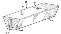
- connector 90which may be employed to establish a linear connection between two frame members which are generally similar to the frame member 22 depicted in FIG. 2 , insofar as these frame members will have an approximately trapezoidal cross section.
- the connectorincludes a core 42 and exterior body 46 as in the FIG. 6 embodiment.
- the connector 90may include features which aid in fixing it to a corresponding frame member.
- the connector 90may include one or more attachment bosses 92 which comprise raised features that can mate with corresponding features in frame members and/or establish a frictional fit with the frame members.
- attachment featuresmay comprise a tooth, a detent, or other such engagement members as is known in the art.
- the connectormay include a body of adhesive, or a component of a two-part adhesive, applied thereto. As is shown in FIG. 9 , one end of the connector 90 is coated with a body of adhesive material 94 .
- This adhesivemay be a contact adhesive, or it may be a curable adhesive such as a heat curable adhesive.
- FIG. 10there is shown a cross-sectional view of a connector 90 , which is generally similar to the connector of FIG. 9 , as disposed to join together two frame members 22 a , 22 b , which are generally similar to the frame member 22 of FIG. 2 . Illustrated in FIG. 10 are several modes whereby the frame members 22 a , 22 b may be interconnected and/or joined to the connector 90 . In particular instances, the frame members and connector may be joined in a frictional fit which can be enhanced by features such as the raised connector bosses 92 as discussed above. In yet other instances, the connection may be enhanced by a tooth, projection or other such feature disposed on the frame members themselves.
- Bonding of the connector and frame membermay also be enhanced by the use of a layer of adhesive material, and as is shown in FIG. 10 , a layer of adhesive 94 is disposed on either end of the connector 90 .
- this adhesivemay comprise a contact adhesive, or it may be a curable adhesive such as a heat curable adhesive.
- further integrity of the frame systemmay be required, and in such cases, the abutting ends of frame members may be joined together by a weld as is shown at reference numeral 98 herein.
- the integrity of the jointmay be further enhanced by the use of an external connector such as a screw, rivet, or the like which is disposed so as to penetrate the frame member and project in and/or through the connector.
- FIG. 11there is shown a perspective view of a corner connector as configured to join four tubular frame members together.
- the connectorincludes a core 102 , which extends therethrough as is shown by the phantom outline, and an exterior body 104 .
- This connector 100may include enhancements such as frictional bosses, adhesive, and the like as discussed hereinabove with reference to FIGS. 9 and 10 .
- connectorsmay be configured so as to join together frame members having different cross-sectional profiles.
- frame members which have a solid cross-sectional profilemay be favored for particular applications, and in that regard, the connectors may be configured to include sleeves or sockets which receive these solid members therein. All of such embodiments are within the scope of this invention.
- a portion of a reinforcing or coupling membermay project from the material forming the remainder of the connector.
- a metallic pinmay be molded so as to project from a connector, and this pin may serve to engage a frame member, or another connector.
- a connectormay have a tube-like socket member molded therein. This socket may be configured to receive a frame member or another coupler.
- a coupler which defines a socketis fitted into a frame member, and a similar arrangement of connector and frame member is joined thereto by a coupler pin which comprises a third member.
- the connectors themselvesmay be made modular or customizable. That is to say, a connector may be configured so that it can be assembled from a plurality of individual block members. In this manner, a four-way connector may be assembled by affixing two connector portions to a two-way connector. Such assembly may be made by way of joints such as dovetail joints, connector pins and the like. The integrity of such connectors may be further enhanced by the use of adhesives.
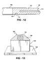
- FIG. 12is a cross-sectional view showing a portion of a frame member which is connected to a connector, a portion of which is shown at 108 .
- the connector 108includes a core 110 , which does not extend along the entire length of the exterior body 112 , although this configuration is not essential for this embodiment.
- the frame member 106is configured to include an inwardly projecting tooth portion 114 which may be formed by a metalworking operation such as piercing, stamping or the like.
- the connector 112includes a groove 116 formed therein, and when the connector 112 is fitted into the frame member 106 , the tooth 114 projects into the groove 116 locking the frame member 106 and connector 112 together.
- This locking actionmay suffice to hold the frame assembly together for ultimate use, or in those instances where high strength is required, this locking mechanism may be utilized to hold the two components in engagement until permanent affixation by means of welding, adhesives, other fasteners or the like may be achieved.
- the locking mechanismmay also function as a locator which facilitates assembly of the frame by assuring that components are appropriately disposed.
- the frame member 106may be configured to receive a projecting portion of a connector member 108 .
- the various componentsmay be correspondingly threaded, provided with bayonet-type locks, or otherwise be configured so as to permit mechanical assembly thereof.
- the connectors of the present inventionwill be configured to allow for initial relative movement of the frame members so that the shape of the frame can be adjusted. After adjustment, the connectors and frame members are immobilized by welding, use of adhesives, mechanical locks, screws, or the like.
- the system of the present inventionmay further include an auxiliary connector optimized for such affixation.
- One such connector 120is shown in FIG. 13 .
- This auxiliary connector 120includes a connector body 122 which is generally similar to the connectors previously described insofar as it includes a core member 124 and an exterior body 126 .
- the exterior profile of the connector body 122is configured to engage with a frame member.
- the auxiliary connector 120 of FIG. 13further includes a connector portion 128 which is configured to be attachable to a third member.
- the connector portion 128is shown as being a flat plate which can be affixed to a rail, frame or other such structure by welding, adhesives, rivets, screws and the like. It is to be understood that the connector portion 128 may be otherwise configured depending upon particular applications. For example, the connector portion may be curved or otherwise irregular in shape, and it may include integral connector members therewith. In some instances, the connector portion 128 may be integral with the core 124 , whereas in other cases it may not. Also, depending upon the particular application, the auxiliary connector 120 may be a simple unitary body and not a composite structure, and in that regard may not include the core and exterior body combination but may be a simple monolithic member.
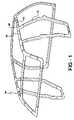
- FIG. 14Ashows a portion of a frame assembly 130 comprised of two frame members 132 , 134 joined together by a connector 136 , which is better illustrated in FIG. 14B .
- the connector 131includes tabs 138 a - 138 c which may be affixed to one frame member, for example frame member 132 in FIG. 14A .
- Such affixationmay be by means of adhesives, welds, separate fasteners or the like.
- mechanical affixationmay be achieved by appropriately configuring the connector and/or frame member.
- FIG. 14Ashows a portion of a frame assembly 130 comprised of two frame members 132 , 134 joined together by a connector 136 , which is better illustrated in FIG. 14B .
- the connector 131includes tabs 138 a - 138 c which may be affixed to one frame member, for example frame member 132 in FIG. 14A .
- Such affixationmay be by means of adhesives, welds,
- the connector 136includes a shelf portion 140 which is disposed so as to receive the frame member 134 .
- the connector 136may be otherwise configured so as to accommodate frame members having different shapes and/or to allow for connection of ear members and/or different configurations of members. This connection system may be utilized in conjunction with, or independently of, the other features of this invention.
- tabs and socketsmay be utilized in the present invention to provide connectors which allow for assembly of frame members into various frame configurations.
- the connectorsmay be manufactured so as to be integral with one of the frame members and engageable with at least one other thereof.
Landscapes
- Engineering & Computer Science (AREA)
- Chemical & Material Sciences (AREA)
- Combustion & Propulsion (AREA)
- Transportation (AREA)
- Mechanical Engineering (AREA)
- Architecture (AREA)
- Structural Engineering (AREA)
- Connection Of Plates (AREA)
- Body Structure For Vehicles (AREA)
- Motor Or Generator Frames (AREA)
Abstract
Description
Claims (18)
Priority Applications (2)
| Application Number | Priority Date | Filing Date | Title |
|---|---|---|---|
| US11/223,884US7251915B2 (en) | 2004-09-10 | 2005-09-09 | Frame system for motor vehicle |
| PCT/US2005/032470WO2006031761A2 (en) | 2004-09-10 | 2005-09-12 | Frame system for motor vehicle |
Applications Claiming Priority (2)
| Application Number | Priority Date | Filing Date | Title |
|---|---|---|---|
| US60864704P | 2004-09-10 | 2004-09-10 | |
| US11/223,884US7251915B2 (en) | 2004-09-10 | 2005-09-09 | Frame system for motor vehicle |
Publications (2)
| Publication Number | Publication Date |
|---|---|
| US20060059807A1 US20060059807A1 (en) | 2006-03-23 |
| US7251915B2true US7251915B2 (en) | 2007-08-07 |
Family
ID=36060624
Family Applications (1)
| Application Number | Title | Priority Date | Filing Date |
|---|---|---|---|
| US11/223,884Expired - Fee RelatedUS7251915B2 (en) | 2004-09-10 | 2005-09-09 | Frame system for motor vehicle |
Country Status (2)
| Country | Link |
|---|---|
| US (1) | US7251915B2 (en) |
| WO (1) | WO2006031761A2 (en) |
Cited By (7)
| Publication number | Priority date | Publication date | Assignee | Title |
|---|---|---|---|---|
| US20100181804A1 (en)* | 2007-06-08 | 2010-07-22 | Giuliano Malvino | Process for constructing the loadbearing structure of a motor vehicle body, and loadbearing structure so constructed |
| US20100237661A1 (en)* | 2009-03-20 | 2010-09-23 | Mohamed Ridha Baccouche | Vehicle body structure |
| US20110175337A1 (en)* | 2010-01-18 | 2011-07-21 | Ferrari S.P.A. | Composite bar for the chassis of a vehicle |
| WO2012125995A1 (en) | 2011-03-17 | 2012-09-20 | Zephyros, Inc. | Bonding assembly |
| US20140183902A1 (en)* | 2012-12-27 | 2014-07-03 | Hyundai Motor Company | Fiber-reinforced plastic vehicle body structure and manufacturing method thereof |
| US20230249757A1 (en)* | 2020-12-21 | 2023-08-10 | Am General Llc | Vehicle frame rails and methods of assembling vehicle frame rails |
| DE102020116936B4 (en) | 2019-12-04 | 2024-09-12 | Hyundai Motor Company | Vehicle body connection structure |
Families Citing this family (21)
| Publication number | Priority date | Publication date | Assignee | Title |
|---|---|---|---|---|
| AU2006227372A1 (en) | 2005-03-17 | 2006-09-28 | Industrial Origami, Inc. | Precision-folded, high strength, fatigue-resistant structures and sheet therefor |
| BRPI0608764A2 (en)* | 2005-03-25 | 2010-01-26 | Ind Origami Inc | three-dimensional structure formed with precision folding technology and forming method |
| US8163116B2 (en)* | 2006-05-09 | 2012-04-24 | Zephyros, Inc. | Joints and a system and method of forming the joints |
| MX2009004478A (en) | 2006-10-26 | 2009-05-28 | Ind Origami Inc | Forming three dimensional object. |
| GB0622027D0 (en)* | 2006-11-06 | 2006-12-13 | Ford Global Tech Llc | A reinforcing member for a motor vehicle |
| US7547063B2 (en)* | 2006-11-14 | 2009-06-16 | Ford Global Technologies, Llc | Unitized vehicle frame subassembly and method of assembling a side frame for a vehicle |
| BRPI0807526A2 (en)* | 2007-02-09 | 2014-06-10 | Ind Origami Inc | THREE-DIMENSIONAL BEARING FRAME |
| DE102007060867A1 (en)* | 2007-12-18 | 2009-06-25 | GM Global Technology Operations, Inc., Detroit | Rear frame structure e.g. for vehicle such as motor vehicle, has, in vehicle longitudinal direction, classified under section with strut |
| CA2715659A1 (en)* | 2008-02-16 | 2009-08-20 | Industrial Origami, Inc. | System for low-force roll folding and methods thereof |
| EP2352665B2 (en) | 2008-11-07 | 2022-02-23 | Zephyros Inc. | Hybrid reinforcement structure |
| BRPI1008335A2 (en)* | 2009-02-10 | 2016-02-23 | Ind Origami Inc | sheet material with curvature control structures and method |
| US8870488B2 (en)* | 2009-06-19 | 2014-10-28 | Duracase Proprietary Llc | Joint assembly with reinforcing member and foam |
| KR101999730B1 (en)* | 2010-05-07 | 2019-07-12 | 더 제너럴 하스피탈 코포레이션 | Method and apparatus for tissue grafting and copying |
| US8936164B2 (en) | 2012-07-06 | 2015-01-20 | Industrial Origami, Inc. | Solar panel rack |
| AT517388B1 (en)* | 2015-06-22 | 2017-03-15 | Hintsteiner Group Gmbh | Frame construction and method of manufacturing a frame construction |
| US9988093B2 (en)* | 2016-09-28 | 2018-06-05 | Ford Global Technologies, Llc | Exoskeleton vehicle upper body structure |
| KR20210070808A (en)* | 2019-12-05 | 2021-06-15 | 현대자동차주식회사 | Body for vehicles |
| KR102792223B1 (en) | 2019-12-05 | 2025-04-07 | 현대자동차주식회사 | Vehicle body forming structure and vehicle body using thereof |
| KR102807537B1 (en) | 2019-12-05 | 2025-05-13 | 현대자동차주식회사 | Body for vehicles |
| KR102757874B1 (en) | 2019-12-05 | 2025-01-21 | 현대자동차주식회사 | Body for vehicles |
| KR102792220B1 (en) | 2019-12-05 | 2025-04-04 | 현대자동차주식회사 | Body for vehicles |
Citations (20)
| Publication number | Priority date | Publication date | Assignee | Title |
|---|---|---|---|---|
| US4660345A (en)* | 1984-10-10 | 1987-04-28 | Mr. Gasket Company | Vehicle space frame, castings therefor and method for remote construction |
| US4976490A (en) | 1988-10-05 | 1990-12-11 | Ford Motor Company | Reinforced composite structure |
| US4990383A (en)* | 1988-06-07 | 1991-02-05 | Neste Oy | Plastic coated steel tube and method for preparing the same |
| US5041318A (en) | 1988-06-23 | 1991-08-20 | Hulls John R | Composite structural member with integral load bearing joint-forming structure |
| US5209541A (en) | 1992-04-13 | 1993-05-11 | Ford Motor Company | Space frame joint construction |
| US5243874A (en)* | 1992-02-24 | 1993-09-14 | Pittsburgh Tubular Shafting, Inc. | Method and apparatus for telescopically assembling a pair of elongated members |
| US5318819A (en) | 1992-09-26 | 1994-06-07 | Pai Ching Dong | Pipe joining construction of a bicycle frame |
| US5458393A (en) | 1993-08-11 | 1995-10-17 | Alumax Extrusions, Inc. | Space frame apparatus and process for the manufacture of same |
| US5720092A (en)* | 1996-08-21 | 1998-02-24 | General Motors Corporation | Method for hydroforming a vehicle space frame |
| US5806919A (en) | 1996-11-04 | 1998-09-15 | General Motors Corporation | Low density-high density insert reinforced structural joints |
| US6068424A (en) | 1998-02-04 | 2000-05-30 | Henkel Corporation | Three dimensional composite joint reinforcement for an automotive vehicle |
| US6276111B1 (en) | 1999-01-28 | 2001-08-21 | Max Joseph Pittman, Sr. | Structural joint assembly and method therefor |
| US6282790B1 (en) | 1997-10-16 | 2001-09-04 | Cosma International Inc. | Hydroformed space frame and method of manufacturing the same |
| US6299246B1 (en) | 1996-10-08 | 2001-10-09 | Rcc Regional Compact Car Ag | Plastic molded part and construction structure |
| US6412857B2 (en) | 1997-10-16 | 2002-07-02 | Cosma International Inc. | Hydroformed space frame and joints therefor |
| US6435360B1 (en)* | 1997-10-31 | 2002-08-20 | Steven P. Buchmeier | Vehicle supported lift system |
| US6532639B2 (en)* | 2001-06-07 | 2003-03-18 | General Motors Corporation | Hydroformed tubular structures and methods of making |
| US6668457B1 (en)* | 1999-12-10 | 2003-12-30 | L&L Products, Inc. | Heat-activated structural foam reinforced hydroform |
| US6892503B1 (en)* | 2002-12-09 | 2005-05-17 | Ho Sang Kang | Long span canopy frame connectors |
| US6926350B2 (en)* | 2000-11-13 | 2005-08-09 | Cosma International Inc. | Hydroformed space frame and rearward ring assembly therefor |
- 2005
- 2005-09-09USUS11/223,884patent/US7251915B2/ennot_activeExpired - Fee Related
- 2005-09-12WOPCT/US2005/032470patent/WO2006031761A2/enactiveApplication Filing
Patent Citations (21)
| Publication number | Priority date | Publication date | Assignee | Title |
|---|---|---|---|---|
| US4660345A (en)* | 1984-10-10 | 1987-04-28 | Mr. Gasket Company | Vehicle space frame, castings therefor and method for remote construction |
| US4990383A (en)* | 1988-06-07 | 1991-02-05 | Neste Oy | Plastic coated steel tube and method for preparing the same |
| US5041318A (en) | 1988-06-23 | 1991-08-20 | Hulls John R | Composite structural member with integral load bearing joint-forming structure |
| US4976490A (en) | 1988-10-05 | 1990-12-11 | Ford Motor Company | Reinforced composite structure |
| US5243874A (en)* | 1992-02-24 | 1993-09-14 | Pittsburgh Tubular Shafting, Inc. | Method and apparatus for telescopically assembling a pair of elongated members |
| US5209541A (en) | 1992-04-13 | 1993-05-11 | Ford Motor Company | Space frame joint construction |
| US5318819A (en) | 1992-09-26 | 1994-06-07 | Pai Ching Dong | Pipe joining construction of a bicycle frame |
| US5458393A (en) | 1993-08-11 | 1995-10-17 | Alumax Extrusions, Inc. | Space frame apparatus and process for the manufacture of same |
| US5720092A (en)* | 1996-08-21 | 1998-02-24 | General Motors Corporation | Method for hydroforming a vehicle space frame |
| US6299246B1 (en) | 1996-10-08 | 2001-10-09 | Rcc Regional Compact Car Ag | Plastic molded part and construction structure |
| US5806919A (en) | 1996-11-04 | 1998-09-15 | General Motors Corporation | Low density-high density insert reinforced structural joints |
| US6412857B2 (en) | 1997-10-16 | 2002-07-02 | Cosma International Inc. | Hydroformed space frame and joints therefor |
| US6282790B1 (en) | 1997-10-16 | 2001-09-04 | Cosma International Inc. | Hydroformed space frame and method of manufacturing the same |
| US6435360B1 (en)* | 1997-10-31 | 2002-08-20 | Steven P. Buchmeier | Vehicle supported lift system |
| US6332731B1 (en) | 1998-02-04 | 2001-12-25 | Henkel Corporation | Three dimensional composite joint reinforcement for an automotive vehicle |
| US6068424A (en) | 1998-02-04 | 2000-05-30 | Henkel Corporation | Three dimensional composite joint reinforcement for an automotive vehicle |
| US6276111B1 (en) | 1999-01-28 | 2001-08-21 | Max Joseph Pittman, Sr. | Structural joint assembly and method therefor |
| US6668457B1 (en)* | 1999-12-10 | 2003-12-30 | L&L Products, Inc. | Heat-activated structural foam reinforced hydroform |
| US6926350B2 (en)* | 2000-11-13 | 2005-08-09 | Cosma International Inc. | Hydroformed space frame and rearward ring assembly therefor |
| US6532639B2 (en)* | 2001-06-07 | 2003-03-18 | General Motors Corporation | Hydroformed tubular structures and methods of making |
| US6892503B1 (en)* | 2002-12-09 | 2005-05-17 | Ho Sang Kang | Long span canopy frame connectors |
Cited By (14)
| Publication number | Priority date | Publication date | Assignee | Title |
|---|---|---|---|---|
| US20100181804A1 (en)* | 2007-06-08 | 2010-07-22 | Giuliano Malvino | Process for constructing the loadbearing structure of a motor vehicle body, and loadbearing structure so constructed |
| US20100237661A1 (en)* | 2009-03-20 | 2010-09-23 | Mohamed Ridha Baccouche | Vehicle body structure |
| US8186752B2 (en)* | 2009-03-20 | 2012-05-29 | Ford Global Technologies | Vehicle body structure |
| US8424912B2 (en)* | 2010-01-18 | 2013-04-23 | Ferrari S.P.A. | Composite bar for the chassis of a vehicle |
| US20110175337A1 (en)* | 2010-01-18 | 2011-07-21 | Ferrari S.P.A. | Composite bar for the chassis of a vehicle |
| US8689516B2 (en) | 2011-03-17 | 2014-04-08 | Zephyros, Inc. | Bonding assembly |
| WO2012125995A1 (en) | 2011-03-17 | 2012-09-20 | Zephyros, Inc. | Bonding assembly |
| US9303670B2 (en) | 2011-03-17 | 2016-04-05 | Zephyros, Inc. | Bonding assembly |
| US10174778B2 (en) | 2011-03-17 | 2019-01-08 | Zephyros, Inc. | Bonding assembly |
| US20140183902A1 (en)* | 2012-12-27 | 2014-07-03 | Hyundai Motor Company | Fiber-reinforced plastic vehicle body structure and manufacturing method thereof |
| US9758197B2 (en)* | 2012-12-27 | 2017-09-12 | Hyundai Motor Company | Fiber-reinforced plastic vehicle body structure and manufacturing method thereof |
| DE102020116936B4 (en) | 2019-12-04 | 2024-09-12 | Hyundai Motor Company | Vehicle body connection structure |
| US20230249757A1 (en)* | 2020-12-21 | 2023-08-10 | Am General Llc | Vehicle frame rails and methods of assembling vehicle frame rails |
| US12091094B2 (en)* | 2020-12-21 | 2024-09-17 | Am General Llc | Vehicle frame rails and methods of assembling vehicle frame rails |
Also Published As
| Publication number | Publication date |
|---|---|
| WO2006031761A3 (en) | 2006-11-02 |
| WO2006031761A2 (en) | 2006-03-23 |
| US20060059807A1 (en) | 2006-03-23 |
Similar Documents
| Publication | Publication Date | Title |
|---|---|---|
| US7251915B2 (en) | Frame system for motor vehicle | |
| EP1918177B1 (en) | A Structural Member for a Motor Vehicle | |
| US4618163A (en) | Automotive chassis | |
| US4988230A (en) | Extruded node | |
| US5059056A (en) | Extrdued node | |
| US9963172B2 (en) | Body structure of vehicle | |
| DE19506160B4 (en) | Frame construction for motor vehicles | |
| EP1157916B1 (en) | Devices and methods for reinforcing hollow structural members | |
| AU2012279691A1 (en) | Vehicle body structure and method for assembling vehicle body structure | |
| EP1880779A1 (en) | Low-profile high-strength vehicle door beam | |
| JP2001233240A (en) | Vehicle shock absorbing structure | |
| EP1880924B1 (en) | Beam in the form of a sill or of a transverse member in a motor vehicle | |
| EP1560741B1 (en) | Basic support for a vehicle structure and method for the production thereof | |
| JP3219278B2 (en) | Module element and manufacturing method | |
| EP1889776A1 (en) | Method of reinforcement of an open hollow member, in particular made of metal for a vehicle | |
| CN104918844B (en) | Roof frame and method of manufacturing roof frame | |
| EP1296781B1 (en) | A method for producing a structural element with a reinforced bend and a structural element | |
| JP5667519B2 (en) | Instrument panel reinforcement structure for automobiles | |
| JP4297213B2 (en) | Manufacturing method of tubular member with flange | |
| KR102699016B1 (en) | Fender apron assembly for vehicle | |
| DE102010014539A1 (en) | Metal-plastic-composite component i.e. hat shelf, for car, has plastic base body molded at deep drawing sheet, and connection area formed by metallic joining elements that are enclosed by plastic base body area-wise | |
| JP2004330838A (en) | Suspension member and method of manufacturing the same | |
| JP2006096154A (en) | Connection structure | |
| GB2331477A (en) | Connecting elongate metallic members | |
| DE202007019273U1 (en) | Reinforcement element for a vehicle hollow body |
Legal Events
| Date | Code | Title | Description |
|---|---|---|---|
| AS | Assignment | Owner name:PULLMAN INDUSTRIES, INC., MICHIGAN Free format text:ASSIGNMENT OF ASSIGNORS INTEREST;ASSIGNORS:ZIMMERMAN, JIM;MCNULTY, FRANK;MACHROWICZ, TAD;AND OTHERS;REEL/FRAME:016797/0355;SIGNING DATES FROM 20051019 TO 20051023 | |
| AS | Assignment | Owner name:COMERICA BANK, AS AGENT,MICHIGAN Free format text:SECURITY AGREEMENT;ASSIGNORS:NOBLE INTERNATIONAL, LTD.;NOBLE COMPONENTS & SYSTEMS, INC.;NOBLE ADVANCED TECHNOLOGIES, INC.;AND OTHERS;REEL/FRAME:018407/0438 Effective date:20061012 Owner name:COMERICA BANK, AS AGENT, MICHIGAN Free format text:SECURITY AGREEMENT;ASSIGNORS:NOBLE INTERNATIONAL, LTD.;NOBLE COMPONENTS & SYSTEMS, INC.;NOBLE ADVANCED TECHNOLOGIES, INC.;AND OTHERS;REEL/FRAME:018407/0438 Effective date:20061012 | |
| STCF | Information on status: patent grant | Free format text:PATENTED CASE | |
| CC | Certificate of correction | ||
| AS | Assignment | Owner name:NOBLE ADVANCED TECHNOLOGIES, INC., MICHIGAN Free format text:CHANGE OF NAME;ASSIGNOR:PULLMAN INDUSTRIES, INC.;REEL/FRAME:021371/0939 Effective date:20080813 | |
| FEPP | Fee payment procedure | Free format text:PAT HOLDER CLAIMS SMALL ENTITY STATUS, ENTITY STATUS SET TO SMALL (ORIGINAL EVENT CODE: LTOS); ENTITY STATUS OF PATENT OWNER: SMALL ENTITY | |
| REMI | Maintenance fee reminder mailed | ||
| FPAY | Fee payment | Year of fee payment:4 | |
| SULP | Surcharge for late payment | ||
| REMI | Maintenance fee reminder mailed | ||
| FPAY | Fee payment | Year of fee payment:8 | |
| SULP | Surcharge for late payment | Year of fee payment:7 | |
| FEPP | Fee payment procedure | Free format text:MAINTENANCE FEE REMINDER MAILED (ORIGINAL EVENT CODE: REM.); ENTITY STATUS OF PATENT OWNER: SMALL ENTITY | |
| LAPS | Lapse for failure to pay maintenance fees | Free format text:PATENT EXPIRED FOR FAILURE TO PAY MAINTENANCE FEES (ORIGINAL EVENT CODE: EXP.); ENTITY STATUS OF PATENT OWNER: SMALL ENTITY | |
| STCH | Information on status: patent discontinuation | Free format text:PATENT EXPIRED DUE TO NONPAYMENT OF MAINTENANCE FEES UNDER 37 CFR 1.362 | |
| FP | Lapsed due to failure to pay maintenance fee | Effective date:20190807 |