US7251411B1 - Fiber optic cable breakout configuration with “Y” block - Google Patents
Fiber optic cable breakout configuration with “Y” blockDownload PDFInfo
- Publication number
- US7251411B1 US7251411B1US11/491,008US49100806AUS7251411B1US 7251411 B1US7251411 B1US 7251411B1US 49100806 AUS49100806 AUS 49100806AUS 7251411 B1US7251411 B1US 7251411B1
- Authority
- US
- United States
- Prior art keywords
- cable
- tether
- separation block
- section
- channel
- Prior art date
- Legal status (The legal status is an assumption and is not a legal conclusion. Google has not performed a legal analysis and makes no representation as to the accuracy of the status listed.)
- Active
Links
Images


Classifications
- G—PHYSICS
- G02—OPTICS
- G02B—OPTICAL ELEMENTS, SYSTEMS OR APPARATUS
- G02B6/00—Light guides; Structural details of arrangements comprising light guides and other optical elements, e.g. couplings
- G02B6/44—Mechanical structures for providing tensile strength and external protection for fibres, e.g. optical transmission cables
- G02B6/4439—Auxiliary devices
- G02B6/4471—Terminating devices ; Cable clamps
- G02B6/4472—Manifolds
- G02B6/4475—Manifolds with provision for lateral branching
- G—PHYSICS
- G02—OPTICS
- G02B—OPTICAL ELEMENTS, SYSTEMS OR APPARATUS
- G02B6/00—Light guides; Structural details of arrangements comprising light guides and other optical elements, e.g. couplings
- G02B6/44—Mechanical structures for providing tensile strength and external protection for fibres, e.g. optical transmission cables
- G02B6/4439—Auxiliary devices
- G02B6/4471—Terminating devices ; Cable clamps
- G02B6/4476—Terminating devices ; Cable clamps with heat-shrinkable elements
Definitions
- the principles disclosed hereinrelate to fiber optic cable systems. More particularly, the present disclosure relates to fiber optic cable systems having main cables and branch cables.
- Passive optical networksare becoming prevalent in part because service providers want to deliver high bandwidth communication capabilities to customers. Passive optical networks are a desirable choice for delivering high-speed communication data because they may not employ active electronic devices, such as amplifiers and repeaters, between a central office and a subscriber termination. The absence of active electronic devices may decrease network complexity and/or cost and may increase network reliability.
- FIG. 1illustrates a network 100 deploying passive fiber optic lines.
- the network 100may include a central office 110 that connects a number of end subscribers 115 (also called end users 115 herein) in a network.
- the central office 110may additionally connect to a larger network such as the Internet (not shown) and a public switched telephone network (PSTN).
- PSTNpublic switched telephone network
- the network 100may also include fiber distribution hubs (FDHs) 130 having one or more optical splitters (e.g., 1-to-8 splitters, 1-to-16 splitters, or 1-to-32 splitters) that generate a number of individual fibers that may lead to the premises of an end user 115 .
- the various lines of the networkcan be aerial or housed within underground conduits (e.g., see conduit 105 ).
- the portion of network 100 that is closest to central office 110is generally referred to as the F1 region, where F1 is the “feeder fiber” from the central office.
- the F1 portion of the networkmay include a distribution cable having on the order of 12 to 48 fibers; however, alternative implementations may include fewer or more fibers.
- the portion of network 100 that includes an FDH 130 and a number of end users 115may be referred to as an F2 portion of network 100 .
- Splitters used in an FDH 130may accept a feeder cable having a number of fibers and may split those incoming fibers into, for example, 216 to 432 individual distribution fibers that may be associated with a like number of end user locations.
- the network 100includes a plurality of breakout locations 125 at which branch cables (e.g., drop cables, stub cables, etc.) are separated out from main cables (e.g., distribution cables).
- Breakout locationscan also be referred to as tap locations or branch locations and branch cables can also be referred to as breakout cables.
- fibers of the branch cablesare typically spliced to selected fibers of the main cable.
- the interface between the fibers of the main cable and the fibers of the branch cablescan be connectorized.
- Stub cablesare typically branch cables that are routed from breakout locations to intermediate access locations such as a pedestals, drop terminals or hubs. Intermediate access locations can provide connector interfaces located between breakout locations and subscriber locations.
- a drop cableis a cable that typically forms the last leg to a subscriber location. For example, drop cables are routed from intermediate access locations to subscriber locations. Drop cables can also be routed directly from breakout locations to subscriber locations hereby bypassing any intermediate access locations
- Branch cablescan manually be separated out from a main cable in the field using field splices.
- Field splicesare typically housed within sealed splice enclosures. Manual splicing in the field is time consuming and expensive.
- Pre-terminated cable systemsinclude factory integrated breakout locations manufactured at predetermined positions along the length of a main cable (e.g., see U.S. Pat. Nos. 4,961,623; 5,125,060; and 5,210,812).
- pre-terminated cablescan be difficult.
- pre-terminationscan complicate passing pre-terminated cable through the underground conduit typically used to hold fiber optic cable (e.g., 1.25 inch inner diameter conduit).
- fiber optic cablee.g., 1.25 inch inner diameter conduit
- aerial applicationspre-terminations can complicate passing pre-terminated cable through aerial cable retention loops.
- Certain aspects of the disclosurerelate to mid-span breakout configurations for pre-terminated fiber optic distribution cables.
- inventive aspectscan relate to individual features and to combinations of features. It is to be understood that both the forgoing general description and the following detailed description are exemplary and explanatory only and are not restrictive of the broad inventive concepts upon which the embodiments disclosed herein are based.
- FIG. 1shows a prior art passive fiber optic network
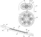
- FIG. 2is a cross sectional view of an example distribution cable
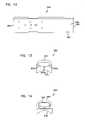
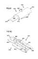
- FIG. 3is a side view of a mid-span breakout location having features that are examples of inventive aspects in accordance with the principles of the present disclosure
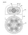
- FIG. 4is a left end view of the mid-span breakout location of FIG. 3 ;
- FIG. 5is a right end view of the mid-span breakout location of FIG. 3 ;
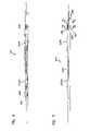
- FIG. 6is a side view of the mid-span breakout location of FIG. 3 with the overmold removed;
- FIG. 7is a side view of the mid-span breakout location of FIG. 3 with the overmold and protective sleeve removed;
- FIG. 7Ais a cross sectional view taken along section line 7 A— 7 A of FIG. 7 ;
- FIG. 7Bis a cross sectional view taken along section line 7 B— 7 B of FIG. 7 ;
- FIG. 8is a cross sectional view of the tether taken along section line 8 — 8 of FIG. 7 ;
- FIG. 9is a perspective view of a base of a retention block used at the mid-span breakout location of FIG. 3 ;
- FIG. 10is a front side view of the base of FIG. 9 ;
- FIG. 11is a top view of the base of FIG. 9 ;
- FIG. 12is a bottom view of the base of FIG. 9 ;
- FIG. 13is a left end view of the base of FIG. 9 ;
- FIG. 14is a right end view of the base of FIG. 9 ;
- FIG. 15is a perspective view of a cover adapted to mount to the base of FIG. 9 ;
- FIG. 16is a top view of the cover of FIG. 15 ;
- FIG. 17is a front side view of the cover of FIG. 15 ;
- FIG. 18is an underside view of the cover of FIG. 15 ;
- FIG. 19is a right end view of the cover of FIG. 15 ;
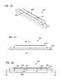
- FIG. 20is a perspective view of a splice stiffener used at the mid-span breakout location of FIG. 3 ;
- FIG. 21is a front side view of the splice stiffener of FIG. 20 ;
- FIG. 22is a top view of the splice stiffener of FIG. 20 ;
- FIG. 23is a bottom view of the splice stiffener of FIG. 20 ;
- FIG. 24is a right end view of the splice stiffener of FIG. 20 ;
- FIG. 25is a cross sectional view taken along section line 25 — 25 of FIG. 22 ;
- FIG. 26is a cross sectional view taken along section line 26 — 26 of FIG. 21 , the splice stiffener is shown mounted on a distribution cable;
- FIG. 27is a perspective view of a stiffener used at the mid-span breakout location of FIG. 3 ;
- FIG. 28is a front side view of the stiffener of FIG. 27 ;
- FIG. 29is a cross sectional view taken along section line 29 — 29 of FIG. 28 ;
- FIG. 30is a cross sectional view taken along section line 30 — 30 of FIG. 28 ;
- FIG. 31is a perspective view of a protective sleeve used at the mid-span breakout location of FIG. 3 ;
- FIG. 32is a front side view of the protective sleeve of FIG. 31 ;
- FIG. 33is a right end view of the protective sleeve of FIG. 31 ;
- FIG. 34is a left end view of the protective sleeve of FIG. 31 ;
- FIG. 35is a top view of the protective sleeve of FIG. 31 ;
- FIG. 36is a cross sectional view taken along section line 36 — 36 of FIG. 32 ;
- FIG. 37is a cross sectional view taken along section line 37 — 37 of FIG. 32 ;
- FIG. 38is a perspective view of a retention clip used to retain the protective sleeve of FIG. 31 at the mid-span breakout location of FIG. 3 ;
- FIG. 39is a front side view of the retention clip of FIG. 38 ;
- FIG. 40is a top view of the retention clip of FIG. 38 ;
- FIG. 41is a bottom view of the retention clip of FIG. 38 ;
- FIG. 42is a right end view of the retention clip of FIG. 38 ;
- FIG. 43is a side view of an overmold used at the mid-span breakout location of FIG. 3 ;
- FIG. 44is a top view of the overmold of FIG. 43 ;
- FIG. 45is a bottom view of the overmold of FIG. 43 ;
- FIG. 46is a left end view of the overmold of FIG. 43 ;
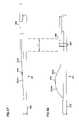
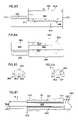
- FIGS. 47 and 48are schematic views showing a method for providing excess fiber length at the mid-span breakout location of FIG. 3 ;
- FIG. 49is a schematic view showing a distribution cable bent along a 90 degree curve at a maximum bend radius
- FIG. 50shows a first preparation step for a tether used at the mid-span breakout location of FIG. 3 ;
- FIG. 51shows a subsequent preparation step of the tether of FIG. 50 ;
- FIG. 52shows an initial preparation of the distribution cable at the mid-span breakout location
- FIG. 53is a perspective view of an example mid-span breakout assembly
- FIG. 54is a perspective view of an example retention block
- FIG. 55is a perspective view of a base of the retention block of FIG. 54 ;
- FIG. 56is a top view of the base of FIG. 55 ;
- FIG. 57is a bottom perspective view of the base of FIG. 55 ;
- FIG. 58is a side view of the base of FIG. 55 ;
- FIG. 59is a transverse cross-sectional view of the base of FIG. 55 ;
- FIG. 60is a front view of the base of FIG. 55 ;
- FIG. 61is a top perspective view of a cover of the retention block of FIG. 54 ;
- FIG. 62is a bottom perspective view of the cover of FIG. 61 ;
- FIG. 63is a side view of the cover of FIG. 61 ;
- FIG. 64is a top view of the cover of FIG. 61 ;
- FIG. 65is a transverse cross-sectional view of the cover of FIG. 61 ;
- FIG. 66is a front view of the cover of FIG. 61 ;
- FIG. 67is a top view of the cover of FIG. 61 showing preparation of a tether cable at an example mid-span breakout location;
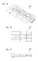
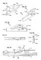
- FIG. 68is a front perspective view of an example separation block
- FIG. 69is a front perspective view of an example first section of the separation block of FIG. 68 ;
- FIG. 70is a rear perspective view of the first section of FIG. 69 ;
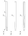
- FIG. 71is a side view of the first section of FIG. 69 ;
- FIG. 72is a top view of the first section of FIG. 69 ;
- FIG. 73is a rear view of the first section of FIG. 69 ;
- FIG. 74is a rear perspective view of an example second section of the separation block of FIG. 68 ;
- FIG. 75is a front perspective view of the second section of FIG. 74 ;
- FIG. 76is a side view of the second section of FIG. 74 ;
- FIG. 77is a top view of the second section of FIG. 74 ;
- FIG. 78is a cross-sectional view of the first section of FIG. 74 ;
- FIG. 79is a side view of the second section of FIG. 74 showing preparation of a distribution cable at an example mid-span breakout location.
- a typical distribution cableincludes a relatively large number of fibers (e.g., 72, 144 or more fibers).
- the fibersare typically segregated into separate groups with each group contained within a separate buffer tube.
- the fibers within each buffer tubecan include either ribbon fibers or loose fibers.
- FIG. 2shows an example distribution cable 220 including six separate buffer tubes 222 each containing twelve fibers 224 .
- the buffer tubes 222may be gel filled.
- the distribution cable 220also includes a central strength member 226 for reinforcing the cable 220 , and an outer strength member 228 such as Kevlar for also reinforcing the cable.
- the distribution cable 220further includes an outer jacket 230 that encloses the buffer tubes 222 . Ripcords 232 can be provided for facilitating tearing away portions of the jacket 230 to access the fibers 224 within the jacket 230 .
- the various aspects of the present disclosureare also applicable to distribution cables having fewer numbers of fibers (e.g., 2 or more fibers).
- the distribution cablecan include an outer jacket enclosing a single buffer tube and at least two strength members extending on opposite sides of the single buffer tube.
- An outer strength membersuch as Kevlar can surround the single buffer tube within the jacket.
- the single buffer tubecan enclose loose fibers or ribbon fibers.
- a typical mid-span breakout locationis provided at an intermediate point along the length of a distribution cable.
- a tethere.g., a drop cable or a stub cable
- branches out from the distribution cable at the breakout locatione.g., a drop cable or a stub cable.
- the tethermost commonly has a fewer number of fibers as compared to the number of fibers provided within the distribution cable. In an example embodiment, the tether has no more than twelve fibers.
- the tetherincludes fibers that extend between first and second ends. The first ends of the tether fibers are preferably spliced to selected fibers of the distribution cable at the breakout location. The second ends of the tether fibers can either be connectorized or unconnectorized.
- FIGS. 3–7illustrate a mid-span breakout assembly 240 having features that are examples of inventive aspects in accordance with the principles of the present disclosure.
- the breakout assemblyis positioned at a mid-span breakout location 241 .
- a tether 242branches outwardly from a main distribution cable 220 at the mid-span breakout location 241 .
- the breakout location 241is shown including a splice location 244 where selected fibers 224 dc of the main distribution cable 220 (e.g., typically less than twelve fibers) are spliced to corresponding fibers 224 t of the tether 242 .
- the breakout assemblyincludes a splice sleeve 246 positioned over the splices, and a splice stiffener 248 for holding the splice sleeve 246 .
- the breakout assembly 240also includes stiffeners 250 1 , 250 2 between which the splice stiffener 248 is positioned.
- the fibers 224 dc from the distribution cable 220pass through the stiffener 250 1 to reach the splice location 244 .
- the fibers 224 t from the tether 242pass through the stiffener 250 2 to reach the splice location 244 .
- the breakout assembly 240further includes a protective sleeve 252 (e.g., a shell) that covers the breakout location 241 .
- the stiffeners 250 1 , 250 2 and the splice stiffener 248are all enclosed within the sleeve 252 .
- a first end 254 of the sleeve 252forms a tapered nose, and a second end 256 of the sleeve 252 overlaps a retention block 258 through which the fibers 224 t of the tether 242 pass.
- Retention clips 243are used to secure the protective sleeve 252 to the distribution cable 220 .
- the breakout assembly 240also includes an over-mold 260 that encloses and seals the protective sleeve 252 , the clips 243 and the retention block 258 .
- a wrap of heat resistant tape 263can provide an intermediate layer between the protective sleeve 252 and the over-mold 260 .
- the tether 242 joined to the distribution cable 220 at the breakout location 241is depicted as having a flat cable configuration.
- the flat cable configurationincludes a central buffer tube 262 containing a plurality of fibers 224 t (e.g., typically one to twelve loose or ribbonized fibers).
- Strength members 264e.g., flexible rods formed by glass fiber reinforced epoxy
- An outer jacket 266surrounds the strength members 264 and the buffer tube 262 .
- the outer jacket 266includes an outer perimeter having an elongated transverse cross-sectional shape.
- An additional strength layer 265(e.g., Kevlar) can be positioned between the buffer tube 262 and the outer jacket 266 .
- the transverse cross-sectional shapeincludes oppositely positioned, generally parallel sides 268 interconnected by rounded ends 270 .
- the tether 242When the tether 242 is secured to the distribution cable 220 , the tether 242 should preferably be able to withstand a pullout force of at least 100 pounds. To meet this pullout force requirement, the retention block 258 is used to strengthen the mechanical interface between the tether 242 and the distribution cable 220 . As shown at FIG. 7 , the retention block 258 includes a base 280 and a cover 282 between which the tether 242 extends. In one embodiment, the retention block 258 has a plastic construction.
- the base 280 of the retention block 258includes a first end 284 positioned opposite from a second end 286 .
- the base 280is elongated along a length A that extends between the first and second ends 284 , 286 .
- the basealso includes a first side 288 adapted to engage the outer surface of the distribution cable jacket, and a second side 290 adapted to engage the tether 242 .
- the first side 288has a channel 292 that extends along the length L of the base 280 .
- the channel 292has a transverse cross-sectional shape that is curved to match the outer diameter of the distribution cable jacket 230 .
- the second side 290 of the base 280includes a retention sleeve 294 defining an elongate opening 296 having a transverse cross-sectional shape that matches the transverse cross-sectional shape of the outer perimeter of the tether cable jacket 266 .
- a jacketed portion of the tether 242fits within the sleeve 294 (see FIG. 7A ).
- the second side 290 of the base 280also includes a central groove 298 a and two side grooves 300 a .
- the grooves 298 a , 300 aare generally parallel and extend along the length of the retention block 258 .
- the central groove 298 ais sized to receive the buffer tube 262 of the tether 242 .
- the side grooves 300 aare sized to receive the strength members 264 of the tether 242 .
- the base 280also includes structures for resisting axial movement between the retention block 258 and the over-mold 260 .
- surface depressions 302are provided adjacent the second end 286 of the base 280 .
- the surface depressions 302(e.g., grooves, slots, cuts, notches, indentations) provide void regions for allowing over-mold material to fill-in during the over-molding process to provide a more secure connection between the retention block 258 and the outer over-mold 260 .
- a mechanical interlockis formed that resists axial movement between the retention block 258 and the over-mold 260 .
- the base 280can include outwardly projecting structures (e.g., flanges, bumps, ribs) that are embedded in the over-mold to further resist axial movement between the over-mold and the retention block.
- the cover 282 of the retention block 258mounts over the second side 290 of the base 280 adjacent the first end 284 of the base 280 .
- the cover 282includes a central groove 298 b and two side grooves 300 b .
- the central groove 298 baligns with the central groove 298 a of the base 280
- the side grooves 300 balign with the side grooves 300 a of the base 280 .
- the buffer tube 262 of the tether 242is captured within the central grooves 298 a , 298 b , and the strength members 264 of the tether 242 are captured within the side grooves 300 a , 300 b (see FIG. 7B ).
- An adhesive 299can be applied between the cover 282 and the base 280 to securely affix the tether 242 to the retention block 258 .
- the adhesive 299is applied to the second side 290 of the base 280 , the grooved side of the cover 282 , the buffer tube 262 of the tether 242 , and the strength members 264 of the tether 242 .
- the retention block 258also includes structures for facilitating aligning the cover 282 on the base 280 .
- the retention block 258can include mating posts 304 and holes 306 provided on the cover 282 and the base 280 .
- the posts 304fit within the holes 306 to maintain alignment between the base 280 and the cover 282 during assembly.
- the retention block 258further includes an outer band groove 308 (see FIGS. 9 and 15 ) that extends around at least a portion of the perimeter of the retention block 258 .
- the band groove 308is sized to receive a strap or band 297 (see FIG. 7 ) that is wrapped around the retention block 258 and the distribution cable 220 to secure the retention block 258 to the distribution cable 258 .
- the bandcan also function to assist in holding the cover 282 on the base 280 .
- the splice stiffener 248 of the breakout assembly 240preferably has a crush-resistant construction adapted to prevent the splices of the breakout location 241 from being damaged.
- the splice stiffener 248is made of a plastic material.
- the splice stiffener 248includes an elongated base portion 320 having a generally half-cylinder shape.
- the base portion 320includes first and second sides 322 , 324 that face in opposite directions.
- the first side 322 of the base portion 320includes a concave surface 325 defining a channel 326 having an open side.
- the concave surface 325is adapted to face toward the buffer tubes 222 of the distribution cable 220 .
- the concave surface 325has a semi-circular shape having a curvature that generally matches an outer diameter D circumscribing the buffer tubes 322 of the distribution cable 320 .
- the concave surface 325is shown covering approximately one half the diameter D, and a plurality of the buffer tubes 222 are shown positioned within the channel 326 .
- the layer formed by the strength members 228may be positioned between the surface 325 and the buffer tubes 222 .
- the splice stiffener 248also includes a pair of parallel retaining members 328 that project outwardly from the second side 324 of the base portion 320 .
- a splice retention channel 330 having an open sideis defined between the retaining members 328 .
- a bed 332 of the channel 330is generally planar.
- Splice sleeve retention ridges or shoulders 334project outwardly from the bed 332 adjacent opposite ends of the channel 330 .
- Snap fit tabs 336project laterally into the channel 330 from the retaining members 328 . In use, the splice sleeve 246 is snap fit between the tabs 336 and into the channel 330 .
- the tabs 336prevent the splice sleeve 246 from unintentionally exiting the splice retention channel 330 through the open side.
- the retention shoulders 334prevent the splice sleeve 246 from sliding out of the splice retention channel 330 through the ends of the splice retention channel 330 .
- the splice sleeve 246is free to slide back and forth between the shoulders 334 within the channel 330 .
- the stiffeners 250 1 , 250 2 of the breakout assembly 240are preferably configured to provide increased crush resistance to the protective sleeve 252 .
- the stiffeners 250 1 , 250 2have a stiffer construction than the protective sleeve 252 and are made of a plastic material.
- the stiffeners 250 1 , 250 2have a generally tubular configuration and each define a through-passage 340 for receiving their respective fibers 224 dc and 224 t .
- the through-passages 340preferably have large enough cross-sectional areas to allow the fibers 224 dc , 224 t to freely slide therein when the breakout location 241 is bent.
- Ends 342 of the passages 340preferably include contours that extend around the perimeter of the passages 340 for preventing the fibers from being bent beyond acceptable bend radius requirements.
- the stiffeners 250 1 , 250 2each include a base portion 344 spaced from an arcuate dome portion 346 .
- the stiffeners 250 1 , 250 2each also include a pair of planar, generally parallel side walls 348 that connect the base portion 344 to the dome portion 346 .
- the base portions 344define concave channels 350 adapted to receive buffer tubes 222 of the distribution cable 220 when the stiffeners 250 1 , 250 2 are positioned at the breakout location 241 .
- the sidewalls 348 and the dome portion 346define an exterior shape that generally matches the interior shape of the protective sleeve 252 .
- the protective sleeve 252 of the mid-span breakout assembly 240is adapted to form a protective shell over the breakout location 241 .
- the protective sleeve 252is preferably sufficiently flexible to allow the pre-terminated cable (i.e., the distribution cable 220 with the tethers terminated 242 thereto) to be readily stored on a spool.
- the stiffeners 248 , 250 1 , 250 2provide regions/segments of increased crush resistance separated by regions/segments of increased flexibility.
- the protective sleeve 252is elongated along a length that extends between the first end 254 and the second end 256 and has a generally U-shaped transverse cross section forming a channel 360 (see FIG. 36 ) with an open side sized to be inserted over the distribution cable.
- the channel 360has a cross sectional shape sized to conform generally with the outer cross sectional shape of the stiffeners 250 1 , 250 2 .
- the internal transverse cross sectional shape of the channel 360is sized to accommodate sufficient slack or excess fiber length to allow the breakout location 241 to be bent without negatively affecting performance or damaging the fibers of the breakout location.
- the channel 360 of the protective sleeve 252is defined between opposing sidewalls 362 defining openings 364 for receiving snap-fit tabs 366 of the retention clips 243 .
- the sidewalls 362are interconnected by a curved portion 363 .
- the first end 254 of the protective sleeve 252includes a low profile portion 365 that fits closely to the distribution cable 220 .
- the low profile portion 365includes a channel 367 that receives the outer jacket 230 of the distribution cable 220 .
- the channel 367has a diameter that generally matches the outer diameter of the distribution cable 220 .
- the first end 254also includes a transition portion 369 that provides a smooth taper/contour between the low profile portion 365 and a main body of the protective sleeve 252 .
- the low profile portion 365 and the transition portion 369cooperate to provide a smooth transition from the distribution cable 220 to the main outer surface of the protective sleeve 252 .
- the smooth taper provided by the first end (i.e., the leading end/nose) of the protective sleeve 252assists in pulling the cable through underground conduit without snagging the breakout location 241 .
- the second end 256 of the protective sleeve 252forms an enlarged receptacle 372 sized sufficiently large to receive the retention block 258 .
- a tapered transition portion 370is provided between the main body of the protective sleeve 252 and the enlarged receptacle 372 .
- the retention clips 243 of the mid-span breakout assembly 240include curved portions 380 that receive the distribution cable 220 on the opposite side of the protective sleeve 252 such that the distribution cable 220 is captured between the clips 243 and the protective sleeve 252 .
- the clips 243also include straight extensions 382 that project upwardly from the curved portion 380 .
- the extensions 382 of the clips 243fit inside the protective sleeve 252 and assist in preventing fibers 224 dc , 224 t from being pinched between the protective sleeve 252 and the distribution cable 220 or the clips 243 .
- the extensions 382include snap-fit tabs 366 that fit within the openings 364 of the protective sleeve 252 .
- the clips 243also include discrete stops 384 for engaging bottom edges of the protection sleeve 252 .
- the stops 384are located at the exteriors of the clips 343 and project outwardly from the curved portions 380 .
- the over-mold 260 of the mid-span breakout assembly 240is preferably made of a polymer plastic material. As shown at FIGS. 43–46 , the over-mold 260 has a primary contour 390 at a leading edge configured to coincide generally with the contour of the leading end of the protective sleeve 252 . A trailing end 392 of the over-mold 260 is also slightly contoured.
- the transverse cross sectional shape of the over-moldincludes first and second curved portions 395 , 396 interconnected by generally planar portions 397 , 398 .
- the over-mold 360is sized with a cross sectional shape sufficient to allow the breakout location to be readily passed through a one and one-half inch inner diameter conduit or a one and one-quarter inch diameter conduit.
- the breakout locationhas a cross sectional area that can be passed through a one inch inner diameter conduit.
- the mid-span breakout location 241is preferably configured to allow the mid-span breakout location to be bent/flexed in any orientation without damaging the fibers 224 dc , 224 t and without significantly negatively affecting cable performance. In one embodiment, this flexibility is provided by making sure that the fibers 224 dc , 224 t have sufficient excess fiber length (i.e., slack) to allow the breakout location to be bent/flexed the requisite amount. In one embodiment, the fibers 224 dc , 224 t that extend along the mid-span breakout location 241 are provided with at least 2% excess fiber length. In other embodiments, the fibers 224 dc , 224 t are provided with at least 3% excess fiber length.
- the fibers 224 dc , 224 tare provided with an excess fiber length in the range of 1 to 5% or in the range of 2 to 5%.
- the length of the mid-span breakout location 241is about 32 centimeters and about 1 centimeter of excess fiber length is provided to the fibers 224 dc , 224 t as they extend along the mid-span breakout location 241 .
- the mid-span breakout assembly 240When the mid-span breakout assembly 240 is assembled, measures are taken to provide the fibers 224 dc , 224 t with excess fiber length. For example, after the fibers 224 dc , 224 t have been fused together, the fibers 224 dc , 224 t are pulled taut and the retention block 258 is positioned against the outer jacket 230 of the distribution cable 220 (see FIG. 47 ). The retention block 258 is then slid a distance X along the distribution cable 220 to the position of FIG. 48 . With the retention block 258 in the position of FIG. 48 , and adequate amount of excess slack/excess fiber length has been provided to the fibers 224 dc , 224 t .
- a securement structure 297e.g., a band, strap, clamp or other type of structure
- the remainder of the mid-span breakout assembly 240can be assembled over the mid-span breakout location 241 .
- an example minimum bend radius R mis ten times the outer diameter of the distribution cable 220 .
- R dcequals the outer radius of the distribution cable measured from the centerline to the outer surface of the outer jacket.
- R dcprovides a value that is representative of the distance between the fibers 224 dc , 224 t and the centerline of the distribution cable.
- the angle of the bendis represented in ⁇ in degrees.
- the excess fiber lengthequals at least ⁇ R dc /2.
- the excess fiber lengthequals ⁇ R dc .
- a portion of the outer jacket 266is stripped away to expose the central buffer tube 262 and the strength members 264 (see FIG. 50 ). As shown at FIG. 50 , the central buffer tube 262 and the strength members 264 project outwardly beyond an end 271 of the outer jacket 266 . As shown at FIG. 50 , the strength layer 265 has been removed from around the buffer tube 262 . After removing the end portion of the outer jacket 266 , the strength members 264 are trimmed as shown at FIG. 51 , and an end portion of the central buffer tube 262 is removed to expose the fibers 224 t .
- the tether 242is then mounted to the base 280 of the retention block 258 .
- the jacketed end 271 of the tether 242is inserted into the retention sleeve 294 .
- the strength members 264are positioned within the side grooves 300 a of the base 280
- the central buffer tube 262is inserted within the central groove 298 a of the base 280 .
- the central buffer tube 262has a length that extends beyond the first end 284 of the base 280 , and the strength members 264 have lengths that terminate generally at the first end of the base 280 .
- a portion of the outer jacket 230is first stripped away to provide a stripped region 400 having an upstream end 402 and a downstream end 404 . Portions of a cable netting can then be removed adjacent the upstream and downstream ends 402 , 404 so that the buffer tubes 222 are exposed.
- the outer strength member 228can also be displaced (e.g., bunched at the bottom side of the cable) adjacent the ends 402 , 404 to facilitate accessing the buffer tubes 222 .
- Tape 406can be used to prevent the intermediate length of netting that remains at the mid-span breakout location 241 from unraveling.
- One of the buffer tubes 222is then selected and a first window 408 is cut into the buffer tube adjacent the upstream end 402 of the stripped region 400 and a second window 410 is cut into the buffer tube 220 adjacent the downstream end 404 of the stripped region 400 .
- the fibers 224 dc desired to be broken outare then accessed and severed at the second window 410 .
- the fibers 224 dcare pulled from the buffer tube 222 through the first window 408 (see FIG. 52 ). With the distribution cable 220 prepared as shown in FIG. 52 , the fibers 224 dc are ready to be terminated to the prepared tether 242 of FIG. 51 .
- the splice sleeve 246 and the two stiffeners 250 1 , 250 2are first slid over the fibers 224 t of the tether and up against the retention block 258 .
- the stiffeners 250 1 , 250 2 and splice sleeve 246can be configured to nest inside one another to minimize the space occupied by such components during the fusion process.
- the componentscan be slid up over the buffer tube 262 of the tether 242 .
- the fibers 224 t of the tetherare fused to the fibers 224 dc of the distribution cable 220 .
- the splice sleeve 246can be slid over the fusion location to protect the splice.
- the fibersare then tested to confirm that the fibers meet minimum insertion loss requirements.
- the cover 282can be adhesively bonded to the base 280 of the retention block 258 to complete the assembly of the retention block.
- the retention block 258is used to pull the fibers 224 dc , 224 t generally taut.
- the splice stiffener 248is positioned beneath the location of the splice sleeve 246 to ensure that the splice sleeve 246 is generally centered relative to the splice stiffener 248 .
- the splice stiffener 248can then be secured to the distribution cable 220 with tape.
- the splice stiffener 248is generally centrally located between the ends 402 , 404 of the stripped region 400 of the distribution cable 220 .
- the retention block 258is slid back along the distribution cable 220 to provide the fibers 224 dc , 224 t with sufficient excess fiber length to allow bending of the mid-span access location. The retention block 258 is then affixed to the distribution cable 220 .
- the stiffeners 250 1 , 250 2are preferably slid along the fibers 224 dc , 224 t to their appropriate stiffening positions.
- the stiffener 250 1is placed generally at a midpoint between the upstream end 402 of the stripped region 400 and the splice stiffener 248
- the stiffener 250 2is positioned generally at a midpoint between the splice stiffener 248 and the downstream end 404 of the stripped region 400 .
- the protective sleeve 252is secured over the stripped region 400 by the retention clips 243 , and the heat resistant tape 263 is wrapped around the mid-span breakout location 241 . Thereafter, the process is completed by applying the over mold 260 over the taped mid-span breakout location.
- the over mold layerfunctions to seal and protect the underlying components of the mid-span breakout assembly 240 .
- the distribution cable 220can be spooled. It is preferred for the fibers 224 t of the tether to be pre-terminated to the fibers 224 dc of the distribution cable.
- Pre-terminatedmeans that the fibers 224 t are fused or otherwise connected to the fibers 224 dc of the distribution cable 220 at the factory as part of the cable manufacturing process rather than being field terminated.
- the remainder of the mid-span breakout assemblyis also preferably factory installed.
- the mid-span breakout assembly 240 ′includes a separation block 700 located on an upstream end 402 ′ of a breakout location 241 ′ and a retention block 600 located on a downstream end 404 ′ of the breakout location 241 ′.
- the retention block 600strengthens the mechanical interface between the tether cable 242 and the distribution cable 220 .
- the separation block 700routes the optical fibers 224 dc accessed from the buffer tube 222 of the distribution cable 220 to the splice point with the tether cable 242 .
- a tube 800extends from the separation block 700 to the retention block 600 .
- the tube 800protects the spliced optical fibers 224 dc , 224 t along the length of the breakout location 241 ′.
- the retention block 600includes a base 610 and a cover 650 between which the tether 242 extends.
- the retention block 600has a plastic construction.
- the base 610 of the retention block 600extends along a length A ( FIG. 56 ) from a first end 620 to a second end 622 .
- the base 610also includes a first side 626 ( FIG. 57 ) adapted to engage the outer strength member 228 of the distribution cable 220 , and a second side 628 ( FIG. 55 ) adapted to engage the tether 242 .
- the base 610includes a first section 605 and a second section 615 ( FIG. 56 ).
- the first section 605 of the base 610includes side surfaces 601 , elongated along a length L, that extend from one end 622 of the base 610 to an intermediate end 621 of the base 610 .
- the second section 615protrudes outwardly from the intermediate end 621 to the end 620 of the base 610 .
- the first side 626 of the base 610has a channel 630 that extends along the length L of the first section 605 ( FIG. 57 ).
- the channel 630has a transverse cross-sectional shape ( FIG. 59 ) that is curved to generally match the inner diameter of the distribution cable jacket 230 .
- the channel 630 of the base 610is configured to couple to a stripped region of the distribution cable 220 ( FIG. 53 ).
- the channel 630couples to the outer strength member 228 of the distribution cable.
- the outer strength member 228includes multiple loose strands of Kevlar positioned around the buffer tubes 222 .
- the second side 628 of the first section 605 of the base 610includes a central groove 602 and two side grooves 603 , 604 .
- the grooves 602 – 604are generally parallel and extend along the length L of the first section 605 of the base 610 .
- a transverse cross-section of the first section 605is shown in FIG. 59 .
- the central groove 602is sized to receive the buffer tube 262 of the tether 242 .
- the side grooves 603 , 604are sized to receive the strength members 264 of the tether 242 .
- the second section 615 of the base 610includes a transition flange 612 that extends outwardly from the intermediate end 621 of the base 610 .
- the transition flange 612has a generally U-shaped transverse cross-section.
- the transition flange 612defines a groove 617 ( FIG. 55 ).
- the cover 650 of the retention block 600mounts over the second side 628 of the base 610 .
- the cover 650includes a first section 655 and a second section 665 .
- the cover 650also includes a first side 676 ( FIG. 61 ) and a grooved side 678 ( FIG. 62 ).
- the first side 676 of the first section 655includes a curved top surface 651 extending from the intermediate end 671 to the first end 672 .
- a transition flange 662having a generally U-shaped transverse cross-section extends outwardly from the intermediate end 671 to a second end 670 .
- the grooved side 678 of the first section 655 of the cover 650includes a central groove 652 and two side grooves 653 , 654 .
- the cover 650is mounted onto the base 610 to align the central groove 652 of the cover 650 with the central groove 602 of the base 610 , and to align the side grooves 653 , 654 of the cover 650 with the side grooves 603 , 604 of the base 610 .
- the buffer tube 262 of the tether 242is captured within the central grooves 602 , 652
- the strength members 264 of the tether 242are captured within the side grooves 603 , 653 , 604 , 654 ( FIG. 67 ).
- An adhesivecan be applied between the cover 650 and the base 610 to securely affix the tether 242 to the retention block 600 .
- the adhesiveis applied to the second side 628 of the base 610 , the grooved side 678 of the cover 650 , the buffer tube 262 of the tether 242 , and the strength members 264 of the tether 242 .
- the retention block 600also includes structures for facilitating aligning the cover 650 on the base 610 .
- the retention block 600can include mating posts 668 and surface depressions (e.g., grooves, slots, cuts, notches, indentations) 608 provided on the cover 650 and the base 610 .
- the posts 668fit within the notches 608 to maintain alignment between the base 610 and the cover 650 during assembly.
- mating posts 668protrude downwardly from the cover 650 to engage with slots 608 on the side surfaces 601 of the base 610 .
- other suitable alignment memberscould also be used.
- a portion of the outer jacket 266 of the tether cable 242is stripped away to expose the central buffer tube 262 and the strength members 264 .
- the central buffer tube 262 and the strength members 264project outwardly beyond an end 271 of the outer jacket 266 .
- the strength layer 265has been displaced from around the buffer tube 262 .
- the strength members 264are trimmed as shown at FIG. 67 , and an end portion of the central buffer tube 262 is removed to expose the fibers 224 t .
- the tether 242is then mounted to the base 610 of the retention block 600 .
- the strength members 264are positioned within the side grooves 603 , 604 of the base 610 , and the central buffer tube 262 is inserted within the central groove 602 of the base 610 .
- the central buffer tube 262has a length that extends beyond the intermediate end 621 of the base 610 , and the strength members 264 have lengths that terminate generally at the intermediate end 621 of the base 610 .
- the central buffer tube 262extends beyond the end 620 of the retention block 600 . In other embodiments, however, the central buffer tube 262 terminates between the intermediate end 621 and end 620 .
- a separation block 700provides support for transitioning fibers 224 dc from the distribution cable 220 to a fusion location.
- the separation block 700includes a Y-shaped housing 701 defining a first opening 711 on an upstream end of the separation block 700 , a second opening 712 on a downstream end of the separation block, and a third opening 714 also located on the downstream end.
- a generally tubular section 716 of the housing 701forms the first opening 711 and generally tubular sections 718 , 719 of the housing 701 form the second and third openings 712 , 714 .
- the second opening 712is generally aligned with the first opening 711 to form a first channel 715 ( FIGS. 71 and 76 ).
- the third opening 714leads to a second channel 717 (see FIGS. 71 and 76 ) that joins with the first channel 715 at the tubular section 716 of the housing 701 .
- Tubular sections 716 , 718 forming the first channel 715are sized and shaped to enclose the buffer tubes 222 and central strength member 226 of the distribution cable 220 .
- Tubular section 719 forming the second channel 717is sized and shaped to fit within the tube 800 and to enclose the fibers 224 dc accessed from the distribution cable 220 for splicing with the fibers 224 t of the tether cable 242 .
- the separation block 700is formed from a first section 710 and a second section 750 .
- the first and second sections 710 , 750each include grooves 715 a , 715 b that align and combine to form the channel 715 .
- aligning and combining grooves 717 a , 717 bforms the channel 717 .
- a protruding section 720 adefines the grooves 715 a , 717 a and a protruding section 720 b defines the grooves 715 b , 717 b.
- the first and second sections 710 , 750are fastened together with complementary surface depressions 722 and protrusions 724 ( FIGS. 70 and 75 ).
- the protruding section 720 a on the first section 710defines a hole 722 and the protruding section 720 b on the second section 750 includes a protrusion 724 sized to fit within the hold 722 .
- Adhesivecan also be used to secure the first section 710 to the second section 750 .
- the mid-span breakout location on the distribution cable 220can be prepared in a similar manner to the preparation discussed above with respect to FIG. 52 .
- a portion of the outer jacket 230 of the distribution cable 220is first stripped away to provide a stripped region 400 ′ ( FIG. 53 ).
- One of the buffer tubes 222is selected and a first window 408 ′ and a second window are cut into the selected buffer tube 222 .
- the fibers 224 dc desired to be broken outare then accessed, severed, and pulled from the buffer tube 222 through the first window 408 ′.
- the severed fibers 224 dcare ready to be fused with the tether fibers 224 t .
- the splice sleeve 246 and the tube 800( FIG. 53 ) are first slid over the fibers 224 t of the tether 242 , and the tube 800 is further slid up over the tether jacket 266 . With the splice sleeve 246 and tube 800 mounted on the tether 242 , the fibers 224 t of the tether are fused to the fibers 224 dc of the distribution cable 220 . The fibers are then tested to confirm that the fibers meet minimum insertion loss requirements.
- the splice sleeve 246can be slid over the fusion location to protect the splice.
- the splice sleeve 246has a length of less than 40 mm.
- the splice sleeve 246has a length of less than 35 mm.
- the splice sleeve 246has a length of about 30 mm.
- the splice sleeve 246has a length of less than 30 mm. Decreasing the length of the splice sleeve 246 increases the degree to which the mid-span breakout assembly can bend. Increasing the flexibility of the breakout assembly 240 , 240 ′ facilitates wrapping the distribution cable 220 having the breakout assembly 240 , 240 ′ around a spool.
- the tube 800can be slid over the splice sleeve 246 and the fusion location to protect the spliced fibers 224 dc , 224 t .
- the separation block 700can then be added to the upstream location 402 ′ of the stripped portion 400 ′ of the distribution cable 220 .
- the buffer tubes 222are routed through the first channel 715 of the separation block 700 and the severed fibers 224 dc are routed through the second channel 717 of the separation block 700 ( FIG. 80 ).
- the buffer tubes 222are laid within the first groove 715 a of the first section 710 of the separation block 700 and the fibers 224 dc are laid within the second groove 717 a of the first section 710 as shown in FIG. 79 .
- the second section 750 of the separation block 700can be secured to the first section as discussed above.
- the separation block 700does not enclose the outer strength member 228 .
- the outer strength member 228can be redistributed uniformly about the buffer tubes 222 of the distribution cable 220 at the upstream and downstream ends 402 ′, 404 ′ after installing the separation block 700 . In such embodiments, the outer strength member 228 extends across the breakout location 241 ′.
- the tube 800can be slid onto section 719 of the separation block 700 .
- the tube 800can optionally be taped or otherwise temporarily secured to the separation block 700 .
- the tube 800is permanently secured to the separation block 700 with adhesive.
- the tube 800is not secured to the separation block 700 .
- the retention block 600is then mounted to the tether cable 242 .
- the retention block 600is preferably positioned so that one end of the tube 800 is slid over the transition flanges 612 , 662 of the retention block 600 and the other end of the tube 800 remains over section 719 of the separation block 700 .
- the tube 800has an appropriate length to provide the fibers 224 dc , 224 t with sufficient excess fiber length to allow bending of the mid-span access location 241 ′.
- the retention block 600is then affixed to the distribution cable 220 .
- the groove 630 of the base 610 of the retention blockis affixed (e.g., with adhesive) to the outer strength member 228 wrapped around the distribution cable 220 .
- the heat resistant tape/foilcan be wrapped around the mid-span breakout location 241 ′. Thereafter, the process is completed by applying an over mold 260 ′ over the mid-span breakout location 241 ′.
- the over mold layer 260 ′functions to seal and protect the underlying components of the mid-span breakout assembly 240 ′.
- the distribution cable 220can be spooled. It is preferred for the fibers 224 t of the tether to be pre-terminated to the fibers 224 dc of the distribution cable.
- the remainder of the mid-span breakout assembly 240 ′is also preferably factory installed.
- the term “fiber access location”can be any type of location where a fiber can be routed out of a buffer tube.
- Example fiber access locationsinclude windows, ring cut regions, or other openings in a buffer tube.
- the fibers 224 dc , 224 tcan collectively be referred to as an optical fiber structure.
- the optical fiber structureincludes a first length of optical fiber within the distribution cable, a second length of optical fiber that extends through the breakout location and a third length of optical fiber that extends through the tether.
- the first, second and third lengthsare in optical communication with one another so as to define a signal path that extends from the distribution cable, through the breakout location, to the end of the tether.
- optical fiber structurealso includes lengths of optical fibers that do not include intermediate splices.
- breakout portionsof optical fiber include portions of optical fiber that extend along the length of a breakout location.
Landscapes
- Physics & Mathematics (AREA)
- General Physics & Mathematics (AREA)
- Optics & Photonics (AREA)
- Laying Of Electric Cables Or Lines Outside (AREA)
- Light Guides In General And Applications Therefor (AREA)
- Cable Accessories (AREA)
Abstract
Description
Claims (22)
Priority Applications (8)
| Application Number | Priority Date | Filing Date | Title |
|---|---|---|---|
| US11/491,008US7251411B1 (en) | 2006-03-09 | 2006-07-21 | Fiber optic cable breakout configuration with “Y” block |
| PCT/US2007/005832WO2007103436A2 (en) | 2006-03-09 | 2007-03-06 | Fiber optic cable breakout configuration with 'y' block |
| MX2008011527AMX2008011527A (en) | 2006-03-09 | 2007-03-06 | Fiber optic cable breakout configuration with "y" block. |
| AU2007223869AAU2007223869B2 (en) | 2006-03-09 | 2007-03-06 | Fiber optic cable breakout configuration with "Y" block |
| CA002645247ACA2645247A1 (en) | 2006-03-09 | 2007-03-06 | Fiber optic cable breakout configuration with "y" block |
| KR1020087024741AKR20080106968A (en) | 2006-03-09 | 2007-03-06 | Fiber Optic Cable Breakout Structure with “을” Blocks |
| JP2008558375AJP2009529705A (en) | 2006-03-09 | 2007-03-06 | Optical fiber breakout configuration with Y block |
| EP07752524AEP1999505A2 (en) | 2006-03-09 | 2007-03-06 | Fiber optic cable breakout configuration with "y" block |
Applications Claiming Priority (2)
| Application Number | Priority Date | Filing Date | Title |
|---|---|---|---|
| US78128006P | 2006-03-09 | 2006-03-09 | |
| US11/491,008US7251411B1 (en) | 2006-03-09 | 2006-07-21 | Fiber optic cable breakout configuration with “Y” block |
Publications (1)
| Publication Number | Publication Date |
|---|---|
| US7251411B1true US7251411B1 (en) | 2007-07-31 |
Family
ID=38290363
Family Applications (1)
| Application Number | Title | Priority Date | Filing Date |
|---|---|---|---|
| US11/491,008ActiveUS7251411B1 (en) | 2006-03-09 | 2006-07-21 | Fiber optic cable breakout configuration with “Y” block |
Country Status (8)
| Country | Link |
|---|---|
| US (1) | US7251411B1 (en) |
| EP (1) | EP1999505A2 (en) |
| JP (1) | JP2009529705A (en) |
| KR (1) | KR20080106968A (en) |
| AU (1) | AU2007223869B2 (en) |
| CA (1) | CA2645247A1 (en) |
| MX (1) | MX2008011527A (en) |
| WO (1) | WO2007103436A2 (en) |
Cited By (33)
| Publication number | Priority date | Publication date | Assignee | Title |
|---|---|---|---|---|
| US20070104446A1 (en)* | 2005-11-10 | 2007-05-10 | Adc Telecommunications, Inc. | Fiber optic cable breakout system, packaging arrangement, and method of installation |
| US20070196068A1 (en)* | 2006-02-22 | 2007-08-23 | Julian Mullaney | Fiber optic cable systems and kits and methods for terminating the same |
| US20070212005A1 (en)* | 2006-03-09 | 2007-09-13 | Adc Telecommunications, Inc. | Mid-span breakout with helical fiber routing |
| US20080080818A1 (en)* | 2006-08-14 | 2008-04-03 | Cobb John C Iii | Factory Spliced Cable Assembly |
| US20080089652A1 (en)* | 2006-10-13 | 2008-04-17 | Dennis Ray Wells | Overmold zip strip |
| US20080145008A1 (en)* | 2006-12-14 | 2008-06-19 | Christopher Paul Lewallen | Cable assembly with selectively extendable tether |
| US20090022459A1 (en)* | 2006-03-09 | 2009-01-22 | Adc Telecommunications, Inc. | Fiber optic cable breakout configuration with retention block |
| US20090022460A1 (en)* | 2006-08-14 | 2009-01-22 | Adc Telecommunications, Inc. | Factory Spliced Cable Assembly |
| US20090060445A1 (en)* | 2007-08-27 | 2009-03-05 | Julian Mullaney | Fiber optic cable control clips and enclosure assemblies and methods incorporating the same |
| US20090060431A1 (en)* | 2007-09-05 | 2009-03-05 | Yu Lu | Indoor Fiber Optic Distribution Cable |
| US7532799B2 (en) | 2007-04-12 | 2009-05-12 | Adc Telecommunications | Fiber optic telecommunications cable assembly |
| US20090151167A1 (en)* | 2007-10-16 | 2009-06-18 | Adc Telecommunications, Inc. | Cable Access Tool and Method of Use |
| US7609925B2 (en) | 2007-04-12 | 2009-10-27 | Adc Telecommunications, Inc. | Fiber optic cable breakout configuration with tensile reinforcement |
| US20110317966A1 (en)* | 2008-12-23 | 2011-12-29 | Jt Optical Engine Gmbh + Co. Kg | Spliced joint between two optical fibers, and method for the production of such a spliced joint |
| US20120106906A1 (en)* | 2010-06-09 | 2012-05-03 | Sumitomo Electric Industries, Ltd. | Stranded optical cable with connectors |
| US8582939B2 (en) | 2010-11-23 | 2013-11-12 | Corning Cable Systems Llc | Fiber optic cables with access features |
| US8582940B2 (en) | 2010-10-28 | 2013-11-12 | Corning Cable Systems Llc | Fiber optic cables with extruded access features and methods of making fiber optic cables |
| US8682124B2 (en) | 2011-10-13 | 2014-03-25 | Corning Cable Systems Llc | Access features of armored flat fiber optic cable |
| US8702326B2 (en) | 2012-03-23 | 2014-04-22 | Corning Cable Systems Llc | Splice protector for fiber optic ribbons |
| US8842954B2 (en) | 2012-05-02 | 2014-09-23 | Corning Cable Systems Llc | Cable assembly |
| US8890050B2 (en) | 2011-11-21 | 2014-11-18 | Tyco Electronics Corporation | Photosensor circuits including a regulated power supply comprising a power circuit configured to provide a regulated power signal to a comparator of a pulse-width modulator |
| US8909014B2 (en) | 2012-04-27 | 2014-12-09 | Corning Cable Systems Llc | Fiber optic cable with access features and jacket-to-core coupling, and methods of making the same |
| US9073243B2 (en) | 2010-04-30 | 2015-07-07 | Corning Cable Systems Llc | Fiber optic cables with access features and methods of making fiber optic cables |
| US9176293B2 (en) | 2011-10-28 | 2015-11-03 | Corning Cable Systems Llc | Buffered fibers with access features |
| US9201208B2 (en) | 2011-10-27 | 2015-12-01 | Corning Cable Systems Llc | Cable having core, jacket and polymeric jacket access features located in the jacket |
| US9274302B2 (en) | 2011-10-13 | 2016-03-01 | Corning Cable Systems Llc | Fiber optic cables with extruded access features for access to a cable cavity |
| US9323022B2 (en) | 2012-10-08 | 2016-04-26 | Corning Cable Systems Llc | Methods of making and accessing cables having access features |
| US9360624B2 (en) | 2013-03-22 | 2016-06-07 | Corning Optical Communications LLC | Splice protector for fiber optic ribbons |
| US9482839B2 (en) | 2013-08-09 | 2016-11-01 | Corning Cable Systems Llc | Optical fiber cable with anti-split feature |
| US20170102504A1 (en)* | 2015-10-09 | 2017-04-13 | Commscope Technologies Llc | Method for terminating high fiber count cables |
| US9645341B2 (en) | 2014-02-11 | 2017-05-09 | Commscope Technologies Llc | Cable assembly with connector having twist ability for aligning mating features |
| WO2021007564A1 (en)* | 2019-07-10 | 2021-01-14 | Preformed Line Products Co. | Unitube ribbon breakout |
| US12298585B2 (en) | 2020-01-29 | 2025-05-13 | Corning Research & Development Corporation | Preconnectorized distribution cable assemblies and methods of making using a pull string |
Families Citing this family (3)
| Publication number | Priority date | Publication date | Assignee | Title |
|---|---|---|---|---|
| JP5479733B2 (en) | 2005-07-15 | 2014-04-23 | オーバーン ユニバーシティ | Microscope illumination device and adapter |
| US8167504B2 (en)* | 2008-12-11 | 2012-05-01 | Tyco Electronics Corporation | Fiber optic multi dwelling unit deployment apparatus including a seamed protection jacket |
| EP3464413B1 (en)* | 2016-05-26 | 2021-12-01 | Corning Optical Communications LLC | Material formulation for over mold cover fiber optic cable |
Citations (147)
| Publication number | Priority date | Publication date | Assignee | Title |
|---|---|---|---|---|
| US2047152A (en) | 1932-10-22 | 1936-07-07 | Galvin Mfg Corp | Automobile radio cable |
| US3691505A (en) | 1970-08-20 | 1972-09-12 | Gen Electric | Heater cable splice and method of forming |
| US3845552A (en) | 1972-03-02 | 1974-11-05 | Method of making an encapsulated assembly | |
| US3879575A (en) | 1974-02-21 | 1975-04-22 | Bell Telephone Labor Inc | Encapsulating compound and closure |
| US3912854A (en) | 1970-01-26 | 1975-10-14 | John T Thompson | Encapsulated conductor junction |
| US3912855A (en) | 1973-04-20 | 1975-10-14 | John T Thompson | Encapsulating splice assembly |
| US4085286A (en) | 1974-09-27 | 1978-04-18 | Raychem Corporation | Heat-recoverable sealing article with self-contained heating means and method of sealing a splice therewith |
| US4107451A (en) | 1975-11-19 | 1978-08-15 | Trech, Inc. | Reinforced splice joint and method of making same |
| US4152539A (en) | 1977-10-21 | 1979-05-01 | Northern Telecom Limited | Telecommunication cable splices |
| US4322573A (en) | 1980-03-11 | 1982-03-30 | Northern Telecom Limited | Encapsulation of telecommunications cable splices |
| US4343844A (en) | 1980-11-17 | 1982-08-10 | Eaton Corporation | Shrinkable sleeve adapted for cable and tubing gas flow blocking |
| JPS58105114U (en) | 1982-01-07 | 1983-07-18 | 松下電器産業株式会社 | flyback transformer |
| US4405083A (en) | 1982-03-19 | 1983-09-20 | Northern Telecom Limited | Moulding apparatus for encapsulating cable splices |
| US4413881A (en) | 1979-07-26 | 1983-11-08 | Northern Telecom Limited | Optical fiber hermetic seal |
| EP0115725A1 (en) | 1982-12-28 | 1984-08-15 | Lignes Telegraphiques Et Telephoniques L.T.T. | Optical multipoint connection cable for information distribution, its production process and its application |
| US4467137A (en) | 1982-06-21 | 1984-08-21 | Raychem Limited | Cable breakout article |
| US4475935A (en) | 1981-07-24 | 1984-10-09 | Nippon Telegraph & Telephone Public Corporation | Joining method to obtain elongated coated optical fiber |
| US4481380A (en) | 1982-08-26 | 1984-11-06 | Alden Research Foundation | High voltage insulator for electrical components having telescoping insulative sleeves |
| US4490315A (en) | 1982-02-04 | 1984-12-25 | Northern Telecom Limited | Methods of moulding of plastics articles |
| US4512628A (en) | 1983-05-31 | 1985-04-23 | Gte Products Corporation | Splice casing assembly |
| US4528419A (en) | 1983-12-12 | 1985-07-09 | Northern Telecom Limited | Forming of cable splice closures |
| US4528150A (en) | 1982-09-23 | 1985-07-09 | Northern Telecom Limited | Methods and apparatus for sealing articles |
| JPS60169813A (en) | 1984-02-15 | 1985-09-03 | Sumitomo Electric Ind Ltd | Optical branching terminal |
| US4549039A (en) | 1983-06-08 | 1985-10-22 | Northern Telecom Limited | Telecommunications cable splice closures |
| US4550220A (en) | 1983-11-04 | 1985-10-29 | National Industries, Inc. | Splice insulator assembly |
| JPS60169815U (en) | 1984-04-18 | 1985-11-11 | シャープ株式会社 | flyback transformer |
| US4556281A (en) | 1983-12-19 | 1985-12-03 | Gte Products Corporation | End plug for a fiber optic in-line splice case assembly |
| US4570032A (en) | 1984-09-07 | 1986-02-11 | Northern Telecom Limited | Sealing closure for a cable splice |
| US4581480A (en) | 1984-09-07 | 1986-04-08 | Northern Telecom Limited | Cable splice closure and strain relief |
| US4589939A (en) | 1984-02-17 | 1986-05-20 | Raychem Corporation | Insulating multiple-conductor cables using coated insert means |
| US4591330A (en) | 1984-11-05 | 1986-05-27 | Northern Telecom Limited | Moulding equipment |
| US4592721A (en) | 1982-09-23 | 1986-06-03 | Northern Telecom Limited | Apparatus for sealably encapsulating articles |
| US4595256A (en) | 1982-04-08 | 1986-06-17 | Les Cables De Lyon | Connection between the ends of two undersea optical fiber cables and method of manufacturing said connection |
| JPS6127510B2 (en) | 1982-07-16 | 1986-06-25 | Morita Sangyo Kk | |
| US4609773A (en) | 1985-07-08 | 1986-09-02 | Northern Telecom Limited | Seal assembly |
| JPS61220536A (en) | 1985-03-27 | 1986-09-30 | Hitachi Ltd | Information transmission line for car |
| US4625073A (en) | 1985-03-11 | 1986-11-25 | Raychem Corporation | Cable having a branch-off region sealed with a branch-off article and method of making same |
| JPS61190305U (en) | 1985-05-15 | 1986-11-27 | ||
| US4629597A (en) | 1985-07-08 | 1986-12-16 | Northern Telecom Limited | Forming of cable splice closures |
| US4648919A (en) | 1984-09-18 | 1987-03-10 | Raychem Corp. | Protection of cable splice |
| US4648606A (en) | 1985-07-08 | 1987-03-10 | Northern Telecom Limited | Seals |
| US4654474A (en) | 1985-06-19 | 1987-03-31 | Northern Telecom Limited | Forming of cable splice closures |
| DE3537684A1 (en) | 1985-10-23 | 1987-04-23 | Rheydt Kabelwerk Ag | Optical fibre cable branch and method for producing it |
| US4666537A (en) | 1980-04-24 | 1987-05-19 | Thomas & Betts Corporation | Method of sealing and repairing electrical cables |
| US4670069A (en) | 1984-09-18 | 1987-06-02 | Raychem Corp. | Protection of cable splice |
| US4670980A (en) | 1985-06-28 | 1987-06-09 | Northern Telecom Limited | Manufacture of sealing closures for a telecommunications cable splice |
| US4678866A (en) | 1985-07-08 | 1987-07-07 | Northern Telecom Limited | Forming of cable splice closures |
| US4684764A (en) | 1985-12-09 | 1987-08-04 | Amerace Corporation | High voltage cable splice protector |
| US4701574A (en) | 1985-02-06 | 1987-10-20 | Raychem Corp. | Cable sealing apparatus |
| JPS6254204B2 (en) | 1982-07-17 | 1987-11-13 | Toshiba Kiki Kk | |
| JPS6259906B2 (en) | 1982-03-31 | 1987-12-14 | Fujitsu Ltd | |
| US4725035A (en) | 1985-06-28 | 1988-02-16 | Northern Telecom Limited | Apparatus for manufacture of sealing closures for a telecommunications cable splice |
| US4732628A (en) | 1980-04-24 | 1988-03-22 | Thomas & Betts Corporation | Method of sealing and repairing electrical cables |
| US4747020A (en) | 1986-05-16 | 1988-05-24 | Adc Telecommunications, Inc. | Wire distribution apparatus |
| US4761052A (en) | 1986-01-31 | 1988-08-02 | N. V. Raychem S.A. | Optical fibre splice case |
| US4764232A (en) | 1986-09-26 | 1988-08-16 | Raychem Corporation | Method of protecting a cable splice with a splice closure having pressure measuring means |
| JPS63136007U (en) | 1987-02-25 | 1988-09-07 | ||
| JPS63180915U (en) | 1987-05-15 | 1988-11-22 | ||
| JPS63287916A (en) | 1987-05-21 | 1988-11-25 | Furukawa Electric Co Ltd:The | Terminal of composite cable |
| JPS63310317A (en) | 1987-06-11 | 1988-12-19 | Showa Electric Wire & Cable Co Ltd | Junction structural-unit for submaring cable |
| US4818824A (en) | 1987-08-19 | 1989-04-04 | American Telephone And Telegraph Company, At&T Bell Laboratories | Closure for aerial telephone cable splices |
| US4822434A (en) | 1986-07-10 | 1989-04-18 | Yazaki Corporation | Method for forming cover layer over wire joint |
| JPH01138828A (en) | 1987-08-12 | 1989-05-31 | Tokyo Tsushin Netsutowaaku Kk | Emergency restoration method for multi-core optical cable and emergency restoration system set for that purpose |
| US4875952A (en) | 1984-06-11 | 1989-10-24 | American Telephone And Telegraph Company, At&T Bell Laboratories | Forced encapsulation means for a cable |
| US4884863A (en) | 1989-03-06 | 1989-12-05 | Siecor Corporation | Optical fiber splicing enclosure for installation in pedestals |
| US4913512A (en) | 1983-12-19 | 1990-04-03 | Gte Products Corporation | Fiber optic in-line splice case assembly |
| US4961623A (en) | 1989-09-05 | 1990-10-09 | Siecor Corporation | Preterminated optical cable |
| US4963698A (en) | 1985-05-02 | 1990-10-16 | Raychem Corporation | Cable sealing |
| US5004315A (en) | 1983-10-20 | 1991-04-02 | Furukawa Electric Co., Ltd. | Optical cable and optical cable line |
| US5042901A (en) | 1990-07-31 | 1991-08-27 | Siecor Corporation | Preconnectorized optical splice closure |
| US5046811A (en) | 1989-07-17 | 1991-09-10 | Jung Roger E | Junction box for optical communications cords, and gland assembly for cord |
| US5054868A (en) | 1990-08-29 | 1991-10-08 | The United States Of America As Represented By The Secretary Of The Navy | Armored optical fiber cable interconnection for dual payout systems |
| US5066095A (en) | 1990-02-09 | 1991-11-19 | Alcatel Cable | Jointing box for optical fiber cables |
| US5074808A (en) | 1991-02-06 | 1991-12-24 | Amp Incorporated | Molded strain relief in back shell |
| US5097529A (en) | 1991-03-22 | 1992-03-17 | At&T Bell Laboratories | Space-saving optical fiber cable closure |
| US5099088A (en) | 1989-07-19 | 1992-03-24 | Three Bond Co., Ltd. | Means for splicing wires |
| US5115105A (en) | 1990-02-21 | 1992-05-19 | Amphenol Corporation | Overbraided in-line data bus loom |
| US5121458A (en) | 1991-04-05 | 1992-06-09 | Alcatel Na Cable Systems, Inc. | Preterminated fiber optic cable |
| US5125060A (en) | 1991-04-05 | 1992-06-23 | Alcatel Na Cable Systems, Inc. | Fiber optic cable having spliceless fiber branch and method of making |
| US5185844A (en) | 1991-07-29 | 1993-02-09 | At&T Bell Laboratories | Closure for optical fiber connective arrangements and method of providing same |
| US5194692A (en) | 1990-09-27 | 1993-03-16 | Amphenol Corporation | Uncased data bus coupler |
| US5210812A (en) | 1991-04-05 | 1993-05-11 | Alcatel Na Cable Systems, Inc. | Optical fiber cable having spliced fiber branch and method of making the same |
| US5217808A (en) | 1989-11-29 | 1993-06-08 | At&T Bell Laboratories | Water blocked cable portion and methods of making same |
| US5241611A (en) | 1989-10-04 | 1993-08-31 | British Telecommunications Public Limited Company | Cable joint |
| US5245151A (en) | 1989-04-07 | 1993-09-14 | Minnesota Mining And Manufacturing Company | Method and article for microwave bonding of splice closure |
| US5347089A (en) | 1990-06-22 | 1994-09-13 | Raychem Limited | Branch off |
| US5353367A (en) | 1993-11-29 | 1994-10-04 | Northern Telecom Limited | Distribution frame and optical connector holder combination |
| US5376196A (en) | 1991-07-11 | 1994-12-27 | Kabelmetal Electro Gmbh | Method for sealing the end of a heat-shrunk sleeve |
| US5378853A (en) | 1992-01-29 | 1995-01-03 | Filotex | Shielded multibranch harness |
| US5394502A (en) | 1993-12-21 | 1995-02-28 | United Technologies Corporation | Fiber optic cable harness break-out fitting |
| US5402515A (en) | 1994-03-01 | 1995-03-28 | Minnesota Mining And Manufacturing Company | Fiber distribution frame system, cabinets, trays and fiber optic connector couplings |
| US5410105A (en) | 1992-09-21 | 1995-04-25 | Nitto Denko Corporation | Method for waterproofing junction of main and branch wires and cover therefor |
| USRE34955E (en) | 1989-07-31 | 1995-05-30 | Adc Telecommunications, Inc. | Optical fiber distribution frame |
| US5420958A (en) | 1990-05-21 | 1995-05-30 | Minnesota Mining And Manufacturing Company | Optical fiber distribution center |
| US5440665A (en)* | 1993-04-16 | 1995-08-08 | Raychem Corporation | Fiber optic cable system including main and drop cables and associated fabrication method |
| US5442726A (en) | 1994-02-22 | 1995-08-15 | Hubbell Incorporated | Optical fiber storage system |
| US5450517A (en) | 1994-07-01 | 1995-09-12 | The Whitaker Corporation | Re-enterable fiber optic splicer for data communications |
| US5491766A (en) | 1993-04-16 | 1996-02-13 | Raychem Corporation | Bonding assembly for fiber optic cable and associated method |
| US5509202A (en) | 1992-11-19 | 1996-04-23 | The United States Of America As Represented By The Secretary Of The Navy | Hydrostatic sealing sleeve method for utilizing wire connections |
| US5517592A (en) | 1993-10-22 | 1996-05-14 | Kabelmetal Electro Gmbh | Sleeve for branch or joint areas in optical or electrical cables |
| US5666453A (en) | 1994-07-15 | 1997-09-09 | Roy Witte | Fiber optic jumper cables and tracing method using same |
| US5684911A (en) | 1995-09-01 | 1997-11-04 | Lucent Technologies Inc. | Sub-surface fiber optic splice housing and method of splicing fiber optic cable |
| US5696864A (en) | 1996-09-18 | 1997-12-09 | Communications Technology Corporation | Aerial enclosure for coupling data signals to a customer site |
| US5734776A (en) | 1996-08-28 | 1998-03-31 | Adc Telecommunications, Inc. | Outside plant cross-connect apparatus |
| US5767448A (en) | 1996-09-30 | 1998-06-16 | Raychem Corporation | Sealing device |
| US5778122A (en) | 1996-12-24 | 1998-07-07 | Siecor Corporation | Fiber optic cable assembly for interconnecting optical fibers within a receptacle mounted within the wall of an enclosure |
| US5823646A (en) | 1997-09-02 | 1998-10-20 | Siecor Corporation | Door assembly for optical hardware cabinet |
| US5892870A (en) | 1995-11-16 | 1999-04-06 | Fiber Connections Inc. | Fibre optic cable connector |
| US5945633A (en) | 1996-05-23 | 1999-08-31 | The Siemon Company | Rack mountable cable distribution enclosure having an angled adapter plate bracket |
| US5969294A (en) | 1997-12-31 | 1999-10-19 | Siecor Operations, Llc | Fiber optic connector cabinet with rotatably mounted adapter panels |
| US5997186A (en) | 1998-05-13 | 1999-12-07 | Huynh; Van L. | Hybrid cable splice closure and related methods |
| USRE36592E (en) | 1994-07-01 | 2000-02-29 | Siecor Corporation | Optical receiver stub fitting |
| US6104846A (en) | 1998-07-31 | 2000-08-15 | Litton Systems, Inc. | System for splicing sensors into a multiple fiber optical cable |
| USRE37028E1 (en) | 1994-02-02 | 2001-01-23 | Siecor Corporation | Cable assembly for use with opto-electronic equipment enclosures |
| US6181861B1 (en) | 1997-02-14 | 2001-01-30 | Alcatel | Arrangement for branching a telecommunications cable containing several stranded elements with optical fibers |
| US6215930B1 (en) | 1998-05-11 | 2001-04-10 | Bellsouth Intellectual Property Management Corporation | Remote-splitter fiber optic cable |
| JP2001116968A (en) | 1999-08-11 | 2001-04-27 | Toyokuni Electric Cable Co Ltd | Optical communication trunk cable and branching tool for optical communication trunk cable |
| US6255584B1 (en) | 1994-12-13 | 2001-07-03 | Eurocopter | Shielded bundle of electrical conductors and process for producing it |
| US6376774B1 (en) | 1996-08-22 | 2002-04-23 | Littelfuse Inc. | Housing for cable assembly |
| US6407338B1 (en) | 1997-01-15 | 2002-06-18 | Uniseal, Inc. | Composite sealant and splice case therefor |
| US6466725B2 (en) | 2000-11-29 | 2002-10-15 | Corning Cable Systems Llc | Apparatus and method for splitting optical fibers |
| US6493500B1 (en) | 2000-09-19 | 2002-12-10 | Korea Telecom | Method for mid-span branching of optical fiber cable |
| US6539160B2 (en) | 2000-10-27 | 2003-03-25 | Corning Cable Systems Llc | Optical fiber splicing and connecting assembly with coupler cassette |
| US6579014B2 (en) | 2001-09-28 | 2003-06-17 | Corning Cable Systems Llc | Fiber optic receptacle |
| US6621975B2 (en) | 2001-11-30 | 2003-09-16 | Corning Cable Systems Llc | Distribution terminal for network access point |
| US6619697B2 (en) | 2000-12-27 | 2003-09-16 | Nkf Kabel B.V. | Y-branch splittable connector |
| EP1361465A1 (en) | 2002-05-07 | 2003-11-12 | Corning Cable Systems LLC | High performance, flexible optical fiber furcation |
| US6648520B2 (en) | 2001-09-28 | 2003-11-18 | Corning Cable Systems Llc | Fiber optic plug |
| US6668127B1 (en) | 1999-08-12 | 2003-12-23 | Bellsouth Intellectual Property Corporation | Connectorized inside fiber optic drop |
| US6706968B2 (en) | 2000-04-24 | 2004-03-16 | Tyco Electronics Corporation | Environmentally sealed wrap-around sleeves having a longitudinal sealant chamber |
| US20040074852A1 (en) | 2002-10-21 | 2004-04-22 | Knudsen Clinton M. | High density panel with rotating tray |
| US6764220B2 (en) | 2001-06-08 | 2004-07-20 | Pirelli General Plc | Assembly for use in connecting optical fibers |
| US6810194B2 (en) | 2001-06-15 | 2004-10-26 | Pirelli General Plc | Connecting optical fibers |
| US6819842B1 (en) | 2003-08-14 | 2004-11-16 | Commscope Properties, Llc | Aerial fiber optic system including a sub-distribution system and related methods |
| US20040228589A1 (en) | 2000-05-26 | 2004-11-18 | Melton Stuart R. | Preconnectorized fiber optic drop cables and assemblies for efficient deployment |
| US20040247265A1 (en) | 2000-11-16 | 2004-12-09 | Asahi Glass Company, Ltd. | Branching method for an optical fiber cable |
| US6856748B1 (en) | 2003-09-30 | 2005-02-15 | Corning Cable Systems Llc | Interconnection enclosure having a connector port and preterminated optical connector |
| US20050053342A1 (en) | 2000-05-26 | 2005-03-10 | Melton Stuart R. | Fiber optic drop cables and preconnectorized assemblies having toning portions |
| US20050069275A1 (en) | 2002-01-23 | 2005-03-31 | Jos Brants | Optical fibre tube sealing |
| US20050111799A1 (en) | 2003-11-26 | 2005-05-26 | Cooke Terry L. | Preterminated fiber optic distribution cable |
| US20050111800A1 (en) | 2003-11-26 | 2005-05-26 | Cooke Terry L. | Pre-connectorized fiber optic distribution cable having multifiber connector |
| US20050175308A1 (en) | 2003-12-15 | 2005-08-11 | Elkins Robert B.Ii | Pre-connectorized fiber optic distribution cable |
| US20050259928A1 (en) | 2004-05-24 | 2005-11-24 | Elkins Robert B Ii | Distribution cable assembly having overmolded mid-span access location |
| US20050259930A1 (en) | 2004-05-24 | 2005-11-24 | Elkins Robert B Ii | Methods and apparatus for facilitating cable locating |
| US20050259929A1 (en) | 2004-05-24 | 2005-11-24 | Elkins Robert B Ii | Distribution cable having overmolded mid-span access location with preferential bending |
| US20060056782A1 (en) | 2004-05-24 | 2006-03-16 | Elkins Robert B Ii | Flexible optical closure and other flexible optical assemblies |
| US20060193573A1 (en)* | 2005-02-28 | 2006-08-31 | Greenwood Jody L | Cross-connect fiber optic cables and associated cross-connect sections |
- 2006
- 2006-07-21USUS11/491,008patent/US7251411B1/enactiveActive
- 2007
- 2007-03-06KRKR1020087024741Apatent/KR20080106968A/ennot_activeWithdrawn
- 2007-03-06AUAU2007223869Apatent/AU2007223869B2/ennot_activeExpired - Fee Related
- 2007-03-06MXMX2008011527Apatent/MX2008011527A/enactiveIP Right Grant
- 2007-03-06WOPCT/US2007/005832patent/WO2007103436A2/enactiveApplication Filing
- 2007-03-06EPEP07752524Apatent/EP1999505A2/ennot_activeWithdrawn
- 2007-03-06JPJP2008558375Apatent/JP2009529705A/enactivePending
- 2007-03-06CACA002645247Apatent/CA2645247A1/ennot_activeAbandoned
Patent Citations (158)
| Publication number | Priority date | Publication date | Assignee | Title |
|---|---|---|---|---|
| US2047152A (en) | 1932-10-22 | 1936-07-07 | Galvin Mfg Corp | Automobile radio cable |
| US3912854A (en) | 1970-01-26 | 1975-10-14 | John T Thompson | Encapsulated conductor junction |
| US3691505A (en) | 1970-08-20 | 1972-09-12 | Gen Electric | Heater cable splice and method of forming |
| US3845552A (en) | 1972-03-02 | 1974-11-05 | Method of making an encapsulated assembly | |
| US3912855A (en) | 1973-04-20 | 1975-10-14 | John T Thompson | Encapsulating splice assembly |
| US3879575A (en) | 1974-02-21 | 1975-04-22 | Bell Telephone Labor Inc | Encapsulating compound and closure |
| US4085286A (en) | 1974-09-27 | 1978-04-18 | Raychem Corporation | Heat-recoverable sealing article with self-contained heating means and method of sealing a splice therewith |
| US4107451A (en) | 1975-11-19 | 1978-08-15 | Trech, Inc. | Reinforced splice joint and method of making same |
| US4152539A (en) | 1977-10-21 | 1979-05-01 | Northern Telecom Limited | Telecommunication cable splices |
| US4413881A (en) | 1979-07-26 | 1983-11-08 | Northern Telecom Limited | Optical fiber hermetic seal |
| US4322573A (en) | 1980-03-11 | 1982-03-30 | Northern Telecom Limited | Encapsulation of telecommunications cable splices |
| US4666537A (en) | 1980-04-24 | 1987-05-19 | Thomas & Betts Corporation | Method of sealing and repairing electrical cables |
| US4732628A (en) | 1980-04-24 | 1988-03-22 | Thomas & Betts Corporation | Method of sealing and repairing electrical cables |
| US4343844A (en) | 1980-11-17 | 1982-08-10 | Eaton Corporation | Shrinkable sleeve adapted for cable and tubing gas flow blocking |
| US4475935A (en) | 1981-07-24 | 1984-10-09 | Nippon Telegraph & Telephone Public Corporation | Joining method to obtain elongated coated optical fiber |
| JPS58105114U (en) | 1982-01-07 | 1983-07-18 | 松下電器産業株式会社 | flyback transformer |
| US4490315A (en) | 1982-02-04 | 1984-12-25 | Northern Telecom Limited | Methods of moulding of plastics articles |
| US4405083A (en) | 1982-03-19 | 1983-09-20 | Northern Telecom Limited | Moulding apparatus for encapsulating cable splices |
| JPS6259906B2 (en) | 1982-03-31 | 1987-12-14 | Fujitsu Ltd | |
| US4595256A (en) | 1982-04-08 | 1986-06-17 | Les Cables De Lyon | Connection between the ends of two undersea optical fiber cables and method of manufacturing said connection |
| US4467137A (en) | 1982-06-21 | 1984-08-21 | Raychem Limited | Cable breakout article |
| JPS6127510B2 (en) | 1982-07-16 | 1986-06-25 | Morita Sangyo Kk | |
| JPS6254204B2 (en) | 1982-07-17 | 1987-11-13 | Toshiba Kiki Kk | |
| US4481380A (en) | 1982-08-26 | 1984-11-06 | Alden Research Foundation | High voltage insulator for electrical components having telescoping insulative sleeves |
| US4528150A (en) | 1982-09-23 | 1985-07-09 | Northern Telecom Limited | Methods and apparatus for sealing articles |
| US4592721A (en) | 1982-09-23 | 1986-06-03 | Northern Telecom Limited | Apparatus for sealably encapsulating articles |
| EP0115725A1 (en) | 1982-12-28 | 1984-08-15 | Lignes Telegraphiques Et Telephoniques L.T.T. | Optical multipoint connection cable for information distribution, its production process and its application |
| US4512628A (en) | 1983-05-31 | 1985-04-23 | Gte Products Corporation | Splice casing assembly |
| US4549039A (en) | 1983-06-08 | 1985-10-22 | Northern Telecom Limited | Telecommunications cable splice closures |
| US5004315A (en) | 1983-10-20 | 1991-04-02 | Furukawa Electric Co., Ltd. | Optical cable and optical cable line |
| US4550220A (en) | 1983-11-04 | 1985-10-29 | National Industries, Inc. | Splice insulator assembly |
| US4528419A (en) | 1983-12-12 | 1985-07-09 | Northern Telecom Limited | Forming of cable splice closures |
| US4913512A (en) | 1983-12-19 | 1990-04-03 | Gte Products Corporation | Fiber optic in-line splice case assembly |
| US4556281A (en) | 1983-12-19 | 1985-12-03 | Gte Products Corporation | End plug for a fiber optic in-line splice case assembly |
| JPS60169813A (en) | 1984-02-15 | 1985-09-03 | Sumitomo Electric Ind Ltd | Optical branching terminal |
| US4589939A (en) | 1984-02-17 | 1986-05-20 | Raychem Corporation | Insulating multiple-conductor cables using coated insert means |
| JPS60169815U (en) | 1984-04-18 | 1985-11-11 | シャープ株式会社 | flyback transformer |
| US4875952A (en) | 1984-06-11 | 1989-10-24 | American Telephone And Telegraph Company, At&T Bell Laboratories | Forced encapsulation means for a cable |
| US4581480A (en) | 1984-09-07 | 1986-04-08 | Northern Telecom Limited | Cable splice closure and strain relief |
| US4570032A (en) | 1984-09-07 | 1986-02-11 | Northern Telecom Limited | Sealing closure for a cable splice |
| US4648919A (en) | 1984-09-18 | 1987-03-10 | Raychem Corp. | Protection of cable splice |
| US4670069A (en) | 1984-09-18 | 1987-06-02 | Raychem Corp. | Protection of cable splice |
| US4591330A (en) | 1984-11-05 | 1986-05-27 | Northern Telecom Limited | Moulding equipment |
| US4701574A (en) | 1985-02-06 | 1987-10-20 | Raychem Corp. | Cable sealing apparatus |
| US4625073A (en) | 1985-03-11 | 1986-11-25 | Raychem Corporation | Cable having a branch-off region sealed with a branch-off article and method of making same |
| JPS61220536A (en) | 1985-03-27 | 1986-09-30 | Hitachi Ltd | Information transmission line for car |
| US4963698A (en) | 1985-05-02 | 1990-10-16 | Raychem Corporation | Cable sealing |
| JPS61190305U (en) | 1985-05-15 | 1986-11-27 | ||
| US4654474A (en) | 1985-06-19 | 1987-03-31 | Northern Telecom Limited | Forming of cable splice closures |
| US4725035A (en) | 1985-06-28 | 1988-02-16 | Northern Telecom Limited | Apparatus for manufacture of sealing closures for a telecommunications cable splice |
| US4670980A (en) | 1985-06-28 | 1987-06-09 | Northern Telecom Limited | Manufacture of sealing closures for a telecommunications cable splice |
| US4678866A (en) | 1985-07-08 | 1987-07-07 | Northern Telecom Limited | Forming of cable splice closures |
| US4648606A (en) | 1985-07-08 | 1987-03-10 | Northern Telecom Limited | Seals |
| US4629597A (en) | 1985-07-08 | 1986-12-16 | Northern Telecom Limited | Forming of cable splice closures |
| US4609773A (en) | 1985-07-08 | 1986-09-02 | Northern Telecom Limited | Seal assembly |
| DE3537684A1 (en) | 1985-10-23 | 1987-04-23 | Rheydt Kabelwerk Ag | Optical fibre cable branch and method for producing it |
| US4684764A (en) | 1985-12-09 | 1987-08-04 | Amerace Corporation | High voltage cable splice protector |
| US4761052A (en) | 1986-01-31 | 1988-08-02 | N. V. Raychem S.A. | Optical fibre splice case |
| US4747020A (en) | 1986-05-16 | 1988-05-24 | Adc Telecommunications, Inc. | Wire distribution apparatus |
| US4822434A (en) | 1986-07-10 | 1989-04-18 | Yazaki Corporation | Method for forming cover layer over wire joint |
| US4764232A (en) | 1986-09-26 | 1988-08-16 | Raychem Corporation | Method of protecting a cable splice with a splice closure having pressure measuring means |
| JPS63136007U (en) | 1987-02-25 | 1988-09-07 | ||
| JPS63180915U (en) | 1987-05-15 | 1988-11-22 | ||
| JPS63287916A (en) | 1987-05-21 | 1988-11-25 | Furukawa Electric Co Ltd:The | Terminal of composite cable |
| JPS63310317A (en) | 1987-06-11 | 1988-12-19 | Showa Electric Wire & Cable Co Ltd | Junction structural-unit for submaring cable |
| JPH01138828A (en) | 1987-08-12 | 1989-05-31 | Tokyo Tsushin Netsutowaaku Kk | Emergency restoration method for multi-core optical cable and emergency restoration system set for that purpose |
| US4818824A (en) | 1987-08-19 | 1989-04-04 | American Telephone And Telegraph Company, At&T Bell Laboratories | Closure for aerial telephone cable splices |
| US4884863A (en) | 1989-03-06 | 1989-12-05 | Siecor Corporation | Optical fiber splicing enclosure for installation in pedestals |
| US5245151A (en) | 1989-04-07 | 1993-09-14 | Minnesota Mining And Manufacturing Company | Method and article for microwave bonding of splice closure |
| US5046811A (en) | 1989-07-17 | 1991-09-10 | Jung Roger E | Junction box for optical communications cords, and gland assembly for cord |
| US5099088A (en) | 1989-07-19 | 1992-03-24 | Three Bond Co., Ltd. | Means for splicing wires |
| USRE34955E (en) | 1989-07-31 | 1995-05-30 | Adc Telecommunications, Inc. | Optical fiber distribution frame |
| US4961623A (en) | 1989-09-05 | 1990-10-09 | Siecor Corporation | Preterminated optical cable |
| US5241611A (en) | 1989-10-04 | 1993-08-31 | British Telecommunications Public Limited Company | Cable joint |
| US5335408A (en) | 1989-11-29 | 1994-08-09 | At&T Bell Laboratories | Method of making a water blocked optical fiber cable |
| US5217808A (en) | 1989-11-29 | 1993-06-08 | At&T Bell Laboratories | Water blocked cable portion and methods of making same |
| US5066095A (en) | 1990-02-09 | 1991-11-19 | Alcatel Cable | Jointing box for optical fiber cables |
| US5115105A (en) | 1990-02-21 | 1992-05-19 | Amphenol Corporation | Overbraided in-line data bus loom |
| US5420958A (en) | 1990-05-21 | 1995-05-30 | Minnesota Mining And Manufacturing Company | Optical fiber distribution center |
| US5347089A (en) | 1990-06-22 | 1994-09-13 | Raychem Limited | Branch off |
| US5042901A (en) | 1990-07-31 | 1991-08-27 | Siecor Corporation | Preconnectorized optical splice closure |
| US5054868A (en) | 1990-08-29 | 1991-10-08 | The United States Of America As Represented By The Secretary Of The Navy | Armored optical fiber cable interconnection for dual payout systems |
| US5194692A (en) | 1990-09-27 | 1993-03-16 | Amphenol Corporation | Uncased data bus coupler |
| US5074808A (en) | 1991-02-06 | 1991-12-24 | Amp Incorporated | Molded strain relief in back shell |
| US5097529A (en) | 1991-03-22 | 1992-03-17 | At&T Bell Laboratories | Space-saving optical fiber cable closure |
| US5125060A (en) | 1991-04-05 | 1992-06-23 | Alcatel Na Cable Systems, Inc. | Fiber optic cable having spliceless fiber branch and method of making |
| US5121458A (en) | 1991-04-05 | 1992-06-09 | Alcatel Na Cable Systems, Inc. | Preterminated fiber optic cable |
| US5210812A (en) | 1991-04-05 | 1993-05-11 | Alcatel Na Cable Systems, Inc. | Optical fiber cable having spliced fiber branch and method of making the same |
| US5376196A (en) | 1991-07-11 | 1994-12-27 | Kabelmetal Electro Gmbh | Method for sealing the end of a heat-shrunk sleeve |
| US5185844A (en) | 1991-07-29 | 1993-02-09 | At&T Bell Laboratories | Closure for optical fiber connective arrangements and method of providing same |
| US5378853A (en) | 1992-01-29 | 1995-01-03 | Filotex | Shielded multibranch harness |
| US5410105A (en) | 1992-09-21 | 1995-04-25 | Nitto Denko Corporation | Method for waterproofing junction of main and branch wires and cover therefor |
| US5509202A (en) | 1992-11-19 | 1996-04-23 | The United States Of America As Represented By The Secretary Of The Navy | Hydrostatic sealing sleeve method for utilizing wire connections |
| US5440665A (en)* | 1993-04-16 | 1995-08-08 | Raychem Corporation | Fiber optic cable system including main and drop cables and associated fabrication method |
| US5491766A (en) | 1993-04-16 | 1996-02-13 | Raychem Corporation | Bonding assembly for fiber optic cable and associated method |
| US5528718A (en) | 1993-04-16 | 1996-06-18 | Raychem Corporation | Fiber optic cable system including main and drop cables and associated fabrication method |
| US5657413A (en) | 1993-04-16 | 1997-08-12 | Raychem Corporation | Sealing assembly for a fiber optic cable and associated fabrication method |
| US5517592A (en) | 1993-10-22 | 1996-05-14 | Kabelmetal Electro Gmbh | Sleeve for branch or joint areas in optical or electrical cables |
| US5353367A (en) | 1993-11-29 | 1994-10-04 | Northern Telecom Limited | Distribution frame and optical connector holder combination |
| US5394502A (en) | 1993-12-21 | 1995-02-28 | United Technologies Corporation | Fiber optic cable harness break-out fitting |
| USRE37028E1 (en) | 1994-02-02 | 2001-01-23 | Siecor Corporation | Cable assembly for use with opto-electronic equipment enclosures |
| US5442726A (en) | 1994-02-22 | 1995-08-15 | Hubbell Incorporated | Optical fiber storage system |
| US5402515A (en) | 1994-03-01 | 1995-03-28 | Minnesota Mining And Manufacturing Company | Fiber distribution frame system, cabinets, trays and fiber optic connector couplings |
| US5450517A (en) | 1994-07-01 | 1995-09-12 | The Whitaker Corporation | Re-enterable fiber optic splicer for data communications |
| USRE36592E (en) | 1994-07-01 | 2000-02-29 | Siecor Corporation | Optical receiver stub fitting |
| US5666453A (en) | 1994-07-15 | 1997-09-09 | Roy Witte | Fiber optic jumper cables and tracing method using same |
| US6655016B2 (en) | 1994-12-13 | 2003-12-02 | Societe Anonyme Dite: Eurocopter France | Process of manufacturing a shielded and wear-resistant multi-branch harness |
| US6255584B1 (en) | 1994-12-13 | 2001-07-03 | Eurocopter | Shielded bundle of electrical conductors and process for producing it |
| US5684911A (en) | 1995-09-01 | 1997-11-04 | Lucent Technologies Inc. | Sub-surface fiber optic splice housing and method of splicing fiber optic cable |
| US5825963A (en) | 1995-09-01 | 1998-10-20 | Lucent Technologies Inc. | Sub-surface fiber optic splice housing and method of splicing fiber optic cable |
| US5892870A (en) | 1995-11-16 | 1999-04-06 | Fiber Connections Inc. | Fibre optic cable connector |
| US5945633A (en) | 1996-05-23 | 1999-08-31 | The Siemon Company | Rack mountable cable distribution enclosure having an angled adapter plate bracket |
| US6376774B1 (en) | 1996-08-22 | 2002-04-23 | Littelfuse Inc. | Housing for cable assembly |
| US5734776A (en) | 1996-08-28 | 1998-03-31 | Adc Telecommunications, Inc. | Outside plant cross-connect apparatus |
| US5696864A (en) | 1996-09-18 | 1997-12-09 | Communications Technology Corporation | Aerial enclosure for coupling data signals to a customer site |
| US5767448A (en) | 1996-09-30 | 1998-06-16 | Raychem Corporation | Sealing device |
| US5778122A (en) | 1996-12-24 | 1998-07-07 | Siecor Corporation | Fiber optic cable assembly for interconnecting optical fibers within a receptacle mounted within the wall of an enclosure |
| US6407338B1 (en) | 1997-01-15 | 2002-06-18 | Uniseal, Inc. | Composite sealant and splice case therefor |
| US6181861B1 (en) | 1997-02-14 | 2001-01-30 | Alcatel | Arrangement for branching a telecommunications cable containing several stranded elements with optical fibers |
| US5823646A (en) | 1997-09-02 | 1998-10-20 | Siecor Corporation | Door assembly for optical hardware cabinet |
| US5969294A (en) | 1997-12-31 | 1999-10-19 | Siecor Operations, Llc | Fiber optic connector cabinet with rotatably mounted adapter panels |
| US6215930B1 (en) | 1998-05-11 | 2001-04-10 | Bellsouth Intellectual Property Management Corporation | Remote-splitter fiber optic cable |
| US5997186A (en) | 1998-05-13 | 1999-12-07 | Huynh; Van L. | Hybrid cable splice closure and related methods |
| US6104846A (en) | 1998-07-31 | 2000-08-15 | Litton Systems, Inc. | System for splicing sensors into a multiple fiber optical cable |
| JP2001116968A (en) | 1999-08-11 | 2001-04-27 | Toyokuni Electric Cable Co Ltd | Optical communication trunk cable and branching tool for optical communication trunk cable |
| US6668127B1 (en) | 1999-08-12 | 2003-12-23 | Bellsouth Intellectual Property Corporation | Connectorized inside fiber optic drop |
| US6706968B2 (en) | 2000-04-24 | 2004-03-16 | Tyco Electronics Corporation | Environmentally sealed wrap-around sleeves having a longitudinal sealant chamber |
| US20040228589A1 (en) | 2000-05-26 | 2004-11-18 | Melton Stuart R. | Preconnectorized fiber optic drop cables and assemblies for efficient deployment |
| US20050053342A1 (en) | 2000-05-26 | 2005-03-10 | Melton Stuart R. | Fiber optic drop cables and preconnectorized assemblies having toning portions |
| US6493500B1 (en) | 2000-09-19 | 2002-12-10 | Korea Telecom | Method for mid-span branching of optical fiber cable |
| US6539160B2 (en) | 2000-10-27 | 2003-03-25 | Corning Cable Systems Llc | Optical fiber splicing and connecting assembly with coupler cassette |
| US20040247265A1 (en) | 2000-11-16 | 2004-12-09 | Asahi Glass Company, Ltd. | Branching method for an optical fiber cable |
| US6466725B2 (en) | 2000-11-29 | 2002-10-15 | Corning Cable Systems Llc | Apparatus and method for splitting optical fibers |
| US6619697B2 (en) | 2000-12-27 | 2003-09-16 | Nkf Kabel B.V. | Y-branch splittable connector |
| US6880219B2 (en) | 2000-12-27 | 2005-04-19 | Nkf Kabel B.V. | Method of installing Y-branch splittable connector |
| US6764220B2 (en) | 2001-06-08 | 2004-07-20 | Pirelli General Plc | Assembly for use in connecting optical fibers |
| US6810194B2 (en) | 2001-06-15 | 2004-10-26 | Pirelli General Plc | Connecting optical fibers |
| US6579014B2 (en) | 2001-09-28 | 2003-06-17 | Corning Cable Systems Llc | Fiber optic receptacle |
| US6648520B2 (en) | 2001-09-28 | 2003-11-18 | Corning Cable Systems Llc | Fiber optic plug |
| US6621975B2 (en) | 2001-11-30 | 2003-09-16 | Corning Cable Systems Llc | Distribution terminal for network access point |
| US20050069275A1 (en) | 2002-01-23 | 2005-03-31 | Jos Brants | Optical fibre tube sealing |
| EP1361465A1 (en) | 2002-05-07 | 2003-11-12 | Corning Cable Systems LLC | High performance, flexible optical fiber furcation |
| US20040074852A1 (en) | 2002-10-21 | 2004-04-22 | Knudsen Clinton M. | High density panel with rotating tray |
| US6819842B1 (en) | 2003-08-14 | 2004-11-16 | Commscope Properties, Llc | Aerial fiber optic system including a sub-distribution system and related methods |
| US6856748B1 (en) | 2003-09-30 | 2005-02-15 | Corning Cable Systems Llc | Interconnection enclosure having a connector port and preterminated optical connector |
| US20050276552A1 (en) | 2003-11-26 | 2005-12-15 | Cooke Terry L | Preterminated fiber optic distribution cable |
| US20050111799A1 (en) | 2003-11-26 | 2005-05-26 | Cooke Terry L. | Preterminated fiber optic distribution cable |
| US20050111800A1 (en) | 2003-11-26 | 2005-05-26 | Cooke Terry L. | Pre-connectorized fiber optic distribution cable having multifiber connector |
| US20050175308A1 (en) | 2003-12-15 | 2005-08-11 | Elkins Robert B.Ii | Pre-connectorized fiber optic distribution cable |
| US7016592B2 (en) | 2003-12-15 | 2006-03-21 | Corning Cable Systems Llc | Fiber optic communications network comprising pre-connectorized fiber optic distribution cable |
| US7006739B2 (en) | 2003-12-15 | 2006-02-28 | Corning Cable Systems Llc | Pre-connectorized fiber optic distribution cable |
| US20050259930A1 (en) | 2004-05-24 | 2005-11-24 | Elkins Robert B Ii | Methods and apparatus for facilitating cable locating |
| WO2005119322A1 (en) | 2004-05-24 | 2005-12-15 | Corning Cable Systems Llc | Distribution cable assembly having overmolded mid-span access location |
| US20050259929A1 (en) | 2004-05-24 | 2005-11-24 | Elkins Robert B Ii | Distribution cable having overmolded mid-span access location with preferential bending |
| US20060056782A1 (en) | 2004-05-24 | 2006-03-16 | Elkins Robert B Ii | Flexible optical closure and other flexible optical assemblies |
| US20050259928A1 (en) | 2004-05-24 | 2005-11-24 | Elkins Robert B Ii | Distribution cable assembly having overmolded mid-span access location |
| WO2006044080A1 (en) | 2004-10-13 | 2006-04-27 | Corning Cable Systems Llc | Pre-connectorized fiber optic distribution cable having multifiber connector |
| US20060193573A1 (en)* | 2005-02-28 | 2006-08-31 | Greenwood Jody L | Cross-connect fiber optic cables and associated cross-connect sections |
Non-Patent Citations (8)
Cited By (74)
| Publication number | Priority date | Publication date | Assignee | Title |
|---|---|---|---|---|
| US20070104446A1 (en)* | 2005-11-10 | 2007-05-10 | Adc Telecommunications, Inc. | Fiber optic cable breakout system, packaging arrangement, and method of installation |
| US7418177B2 (en)* | 2005-11-10 | 2008-08-26 | Adc Telecommunications, Inc. | Fiber optic cable breakout system, packaging arrangement, and method of installation |
| US20070196068A1 (en)* | 2006-02-22 | 2007-08-23 | Julian Mullaney | Fiber optic cable systems and kits and methods for terminating the same |
| US20100239215A1 (en)* | 2006-02-22 | 2010-09-23 | Julian Mullaney | Methods for Terminating Optical Fiber Cables |
| US8126304B2 (en) | 2006-02-22 | 2012-02-28 | Tyco Electronics Corporation | Methods for terminating optical fiber cables |
| US7756372B2 (en)* | 2006-02-22 | 2010-07-13 | Tyco Electronics Corporation | Fiber optic cable systems and kits and methods for terminating the same |
| US20070212005A1 (en)* | 2006-03-09 | 2007-09-13 | Adc Telecommunications, Inc. | Mid-span breakout with helical fiber routing |
| US20100080514A1 (en)* | 2006-03-09 | 2010-04-01 | Adc Telecommunications, Inc. | Fiber optic cable breakout configuration with retention block |
| US7630606B2 (en) | 2006-03-09 | 2009-12-08 | Adc Telecommunications, Inc. | Fiber optic cable breakout configuration with retention block |
| US7590321B2 (en)* | 2006-03-09 | 2009-09-15 | Adc Telecommunications, Inc. | Mid-span breakout with helical fiber routing |
| US20090022459A1 (en)* | 2006-03-09 | 2009-01-22 | Adc Telecommunications, Inc. | Fiber optic cable breakout configuration with retention block |
| US20090022460A1 (en)* | 2006-08-14 | 2009-01-22 | Adc Telecommunications, Inc. | Factory Spliced Cable Assembly |
| US7454106B2 (en) | 2006-08-14 | 2008-11-18 | Adc Telecommunications, Inc. | Factory spliced cable assembly |
| US7840109B2 (en) | 2006-08-14 | 2010-11-23 | Adc Telecommunications, Inc. | Factory spliced cable assembly |
| US20080080818A1 (en)* | 2006-08-14 | 2008-04-03 | Cobb John C Iii | Factory Spliced Cable Assembly |
| US7403685B2 (en)* | 2006-10-13 | 2008-07-22 | Adc Telecommunications, Inc. | Overmold zip strip |
| US20080089652A1 (en)* | 2006-10-13 | 2008-04-17 | Dennis Ray Wells | Overmold zip strip |
| US20080145008A1 (en)* | 2006-12-14 | 2008-06-19 | Christopher Paul Lewallen | Cable assembly with selectively extendable tether |
| US7532799B2 (en) | 2007-04-12 | 2009-05-12 | Adc Telecommunications | Fiber optic telecommunications cable assembly |
| US7609925B2 (en) | 2007-04-12 | 2009-10-27 | Adc Telecommunications, Inc. | Fiber optic cable breakout configuration with tensile reinforcement |
| US20090060445A1 (en)* | 2007-08-27 | 2009-03-05 | Julian Mullaney | Fiber optic cable control clips and enclosure assemblies and methods incorporating the same |
| US8135258B2 (en) | 2007-08-27 | 2012-03-13 | Tyco Electronics Corporation | Fiber optic cable control clips and enclosure assemblies and methods incorporating the same |
| US20100142909A1 (en)* | 2007-08-27 | 2010-06-10 | Tyco Electronics Corporation | Fiber optic cable control clips and enclosure assemblies and methods incorporating the same |
| US7738761B2 (en)* | 2007-08-27 | 2010-06-15 | Tyco Electronics Corporation | Fiber optic cable control clips and enclosure assemblies and methods incorporating the same |
| US20110194830A1 (en)* | 2007-08-27 | 2011-08-11 | Tyco Electronics Corporation | Fiber optic cable control clips and enclosure assemblies and methods incorporating the same |
| US7953311B2 (en) | 2007-08-27 | 2011-05-31 | Tyco Electronics Corporation | Fiber optic cable control clips and enclosure assemblies and methods incorporating the same |
| WO2009033030A1 (en)* | 2007-09-05 | 2009-03-12 | Adc Telecommunications, Inc. | Indoor fiber optic distribution cable |
| US20090060431A1 (en)* | 2007-09-05 | 2009-03-05 | Yu Lu | Indoor Fiber Optic Distribution Cable |
| US7769261B2 (en) | 2007-09-05 | 2010-08-03 | Adc Telecommunications, Inc. | Fiber optic distribution cable |
| US20090151167A1 (en)* | 2007-10-16 | 2009-06-18 | Adc Telecommunications, Inc. | Cable Access Tool and Method of Use |
| US8245405B2 (en) | 2007-10-16 | 2012-08-21 | Adc Telecommunications, Inc. | Cable access tool and method of use |
| US20110317966A1 (en)* | 2008-12-23 | 2011-12-29 | Jt Optical Engine Gmbh + Co. Kg | Spliced joint between two optical fibers, and method for the production of such a spliced joint |
| US9658422B2 (en) | 2010-04-30 | 2017-05-23 | Corning Optical Communications LLC | Fiber optic cables with access features and methods of making fiber optic cables |
| US9073243B2 (en) | 2010-04-30 | 2015-07-07 | Corning Cable Systems Llc | Fiber optic cables with access features and methods of making fiber optic cables |
| US20120106906A1 (en)* | 2010-06-09 | 2012-05-03 | Sumitomo Electric Industries, Ltd. | Stranded optical cable with connectors |
| US9176295B2 (en)* | 2010-06-09 | 2015-11-03 | Sumitomo Electric Industries, Ltd. | Stranded optical cable with connectors |
| US10078195B2 (en) | 2010-10-28 | 2018-09-18 | Corning Optical Communications LLC | Fiber optic cables with extruded access features and methods of making fiber optic cables |
| US10302891B2 (en) | 2010-10-28 | 2019-05-28 | Corning Optical Communications LLC | Fiber optic cables with extruded access features and methods of making fiber optic cables |
| US10613288B2 (en) | 2010-10-28 | 2020-04-07 | Corning Optical Communications LLC | Fiber optic cables with extruded access features and methods of making fiber optic cables |
| US9720201B2 (en) | 2010-10-28 | 2017-08-01 | Corning Optical Communications LLC | Fiber optic cables with extruded access features and methods of making fiber optic cables |
| US8909011B2 (en) | 2010-10-28 | 2014-12-09 | Corning Cable Systems Llc | Fiber optic cables with extruded access features and methods of making fiber optic cables |
| US9250411B2 (en) | 2010-10-28 | 2016-02-02 | Ccs Technology, Inc. | Fiber optic cables with extruded access features and methods of making fiber optic cables |
| US8582940B2 (en) | 2010-10-28 | 2013-11-12 | Corning Cable Systems Llc | Fiber optic cables with extruded access features and methods of making fiber optic cables |
| US8737787B2 (en) | 2010-11-23 | 2014-05-27 | Corning Cable Systems Llc | Fiber optic cables with access features |
| US8995809B2 (en) | 2010-11-23 | 2015-03-31 | Corning Optical Communications LLC | Fiber optic cables with access features |
| US8582939B2 (en) | 2010-11-23 | 2013-11-12 | Corning Cable Systems Llc | Fiber optic cables with access features |
| US8682124B2 (en) | 2011-10-13 | 2014-03-25 | Corning Cable Systems Llc | Access features of armored flat fiber optic cable |
| US9664872B2 (en) | 2011-10-13 | 2017-05-30 | Corning Optical Communications LLC | Fiber optic cables with extruded access features for access to a cable cavity |
| US9244244B2 (en) | 2011-10-13 | 2016-01-26 | Corning Optical Communications LLC | Method of manufacturing a fiber optic cable |
| US9274302B2 (en) | 2011-10-13 | 2016-03-01 | Corning Cable Systems Llc | Fiber optic cables with extruded access features for access to a cable cavity |
| US9720202B2 (en) | 2011-10-13 | 2017-08-01 | Corning Optical Communications LLC | Methods of making and accessing cables having access features |
| US10228529B2 (en) | 2011-10-27 | 2019-03-12 | Corning Optical Communications LLC | Cable having core, jacket and polymeric jacket access features located in the jacket |
| US9201208B2 (en) | 2011-10-27 | 2015-12-01 | Corning Cable Systems Llc | Cable having core, jacket and polymeric jacket access features located in the jacket |
| US9703065B2 (en) | 2011-10-27 | 2017-07-11 | Corning Optical Communications LLC | Cable having core, jacket and polymeric jacket access features located in the jacket |
| US9176293B2 (en) | 2011-10-28 | 2015-11-03 | Corning Cable Systems Llc | Buffered fibers with access features |
| US9778434B2 (en) | 2011-10-28 | 2017-10-03 | Corning Optical Communications LLC | Buffered fibers with access features |
| US8890050B2 (en) | 2011-11-21 | 2014-11-18 | Tyco Electronics Corporation | Photosensor circuits including a regulated power supply comprising a power circuit configured to provide a regulated power signal to a comparator of a pulse-width modulator |
| USRE48144E1 (en) | 2012-03-23 | 2020-08-04 | Corning Optical Communications LLC | Splice protector for fiber optic ribbons |
| US8702326B2 (en) | 2012-03-23 | 2014-04-22 | Corning Cable Systems Llc | Splice protector for fiber optic ribbons |
| US8909014B2 (en) | 2012-04-27 | 2014-12-09 | Corning Cable Systems Llc | Fiber optic cable with access features and jacket-to-core coupling, and methods of making the same |
| US8842954B2 (en) | 2012-05-02 | 2014-09-23 | Corning Cable Systems Llc | Cable assembly |
| US9285556B2 (en) | 2012-05-02 | 2016-03-15 | Corning Optical Communications LLC | Cable assembly |
| US9323022B2 (en) | 2012-10-08 | 2016-04-26 | Corning Cable Systems Llc | Methods of making and accessing cables having access features |
| US9360624B2 (en) | 2013-03-22 | 2016-06-07 | Corning Optical Communications LLC | Splice protector for fiber optic ribbons |
| US9482839B2 (en) | 2013-08-09 | 2016-11-01 | Corning Cable Systems Llc | Optical fiber cable with anti-split feature |
| US10254494B2 (en) | 2013-08-09 | 2019-04-09 | Corning Optical Communications LLC | Armored optical fiber cable |
| US10578820B2 (en) | 2013-08-09 | 2020-03-03 | Corning Optical Communications LLC | Armored optical fiber cable |
| US9791652B2 (en) | 2013-08-09 | 2017-10-17 | Corning Optical Communications LLC | Armored optical fiber cable |
| US9645341B2 (en) | 2014-02-11 | 2017-05-09 | Commscope Technologies Llc | Cable assembly with connector having twist ability for aligning mating features |
| US9664864B2 (en)* | 2015-10-09 | 2017-05-30 | Commscope Technologies Llc | Method for terminating high fiber count cables |
| US20170102504A1 (en)* | 2015-10-09 | 2017-04-13 | Commscope Technologies Llc | Method for terminating high fiber count cables |
| WO2021007564A1 (en)* | 2019-07-10 | 2021-01-14 | Preformed Line Products Co. | Unitube ribbon breakout |
| US11448840B2 (en) | 2019-07-10 | 2022-09-20 | Preformed Line Products Co. | Unitube ribbon breakout |
| US12298585B2 (en) | 2020-01-29 | 2025-05-13 | Corning Research & Development Corporation | Preconnectorized distribution cable assemblies and methods of making using a pull string |
Also Published As
| Publication number | Publication date |
|---|---|
| KR20080106968A (en) | 2008-12-09 |
| MX2008011527A (en) | 2008-11-14 |
| AU2007223869B2 (en) | 2012-10-04 |
| WO2007103436A2 (en) | 2007-09-13 |
| EP1999505A2 (en) | 2008-12-10 |
| AU2007223869A1 (en) | 2007-09-13 |
| CA2645247A1 (en) | 2007-09-13 |
| WO2007103436A3 (en) | 2007-11-01 |
| JP2009529705A (en) | 2009-08-20 |
Similar Documents
| Publication | Publication Date | Title |
|---|---|---|
| US7251411B1 (en) | Fiber optic cable breakout configuration with “Y” block | |
| US7317863B2 (en) | Fiber optic cable breakout configuration with retention block | |
| US7422378B2 (en) | Fiber optic cable breakout configuration with excess fiber length | |
| US7454106B2 (en) | Factory spliced cable assembly | |
| US7840109B2 (en) | Factory spliced cable assembly | |
| US7609925B2 (en) | Fiber optic cable breakout configuration with tensile reinforcement | |
| EP1831746B1 (en) | Distribution cable having overmolded mid-span access location with preferential bending | |
| US7590321B2 (en) | Mid-span breakout with helical fiber routing | |
| US7403685B2 (en) | Overmold zip strip | |
| US7088893B2 (en) | Pre-connectorized fiber optic distribution cable having multifiber connector | |
| US7266274B2 (en) | Pre-connectorized fiber optic distribution cable having overmolded access location | |
| US7532799B2 (en) | Fiber optic telecommunications cable assembly | |
| US7418177B2 (en) | Fiber optic cable breakout system, packaging arrangement, and method of installation | |
| US20050111799A1 (en) | Preterminated fiber optic distribution cable | |
| ES2761811T3 (en) | Fiber optic distribution cables and structures therefor |
Legal Events
| Date | Code | Title | Description |
|---|---|---|---|
| AS | Assignment | Owner name:ADC TELECOMMUNICATIONS, INC., MINNESOTA Free format text:ASSIGNMENT OF ASSIGNORS INTEREST;ASSIGNORS:LU, YU;MILLEA, KEITH;GNIADEK, JEFF;REEL/FRAME:018128/0094 Effective date:20060522 | |
| STCF | Information on status: patent grant | Free format text:PATENTED CASE | |
| FPAY | Fee payment | Year of fee payment:4 | |
| FPAY | Fee payment | Year of fee payment:8 | |
| AS | Assignment | Owner name:TYCO ELECTRONICS SERVICES GMBH, SWITZERLAND Free format text:ASSIGNMENT OF ASSIGNORS INTEREST;ASSIGNOR:ADC TELECOMMUNICATIONS, INC.;REEL/FRAME:036060/0174 Effective date:20110930 | |
| AS | Assignment | Owner name:COMMSCOPE EMEA LIMITED, IRELAND Free format text:ASSIGNMENT OF ASSIGNORS INTEREST;ASSIGNOR:TYCO ELECTRONICS SERVICES GMBH;REEL/FRAME:036956/0001 Effective date:20150828 | |
| AS | Assignment | Owner name:COMMSCOPE TECHNOLOGIES LLC, NORTH CAROLINA Free format text:ASSIGNMENT OF ASSIGNORS INTEREST;ASSIGNOR:COMMSCOPE EMEA LIMITED;REEL/FRAME:037012/0001 Effective date:20150828 | |
| AS | Assignment | Owner name:JPMORGAN CHASE BANK, N.A., AS COLLATERAL AGENT, ILLINOIS Free format text:PATENT SECURITY AGREEMENT (TERM);ASSIGNOR:COMMSCOPE TECHNOLOGIES LLC;REEL/FRAME:037513/0709 Effective date:20151220 Owner name:JPMORGAN CHASE BANK, N.A., AS COLLATERAL AGENT, ILLINOIS Free format text:PATENT SECURITY AGREEMENT (ABL);ASSIGNOR:COMMSCOPE TECHNOLOGIES LLC;REEL/FRAME:037514/0196 Effective date:20151220 Owner name:JPMORGAN CHASE BANK, N.A., AS COLLATERAL AGENT, IL Free format text:PATENT SECURITY AGREEMENT (TERM);ASSIGNOR:COMMSCOPE TECHNOLOGIES LLC;REEL/FRAME:037513/0709 Effective date:20151220 Owner name:JPMORGAN CHASE BANK, N.A., AS COLLATERAL AGENT, IL Free format text:PATENT SECURITY AGREEMENT (ABL);ASSIGNOR:COMMSCOPE TECHNOLOGIES LLC;REEL/FRAME:037514/0196 Effective date:20151220 | |
| MAFP | Maintenance fee payment | Free format text:PAYMENT OF MAINTENANCE FEE, 12TH YEAR, LARGE ENTITY (ORIGINAL EVENT CODE: M1553); ENTITY STATUS OF PATENT OWNER: LARGE ENTITY Year of fee payment:12 | |
| AS | Assignment | Owner name:COMMSCOPE TECHNOLOGIES LLC, NORTH CAROLINA Free format text:RELEASE BY SECURED PARTY;ASSIGNOR:JPMORGAN CHASE BANK, N.A.;REEL/FRAME:048840/0001 Effective date:20190404 Owner name:COMMSCOPE, INC. OF NORTH CAROLINA, NORTH CAROLINA Free format text:RELEASE BY SECURED PARTY;ASSIGNOR:JPMORGAN CHASE BANK, N.A.;REEL/FRAME:048840/0001 Effective date:20190404 Owner name:ALLEN TELECOM LLC, ILLINOIS Free format text:RELEASE BY SECURED PARTY;ASSIGNOR:JPMORGAN CHASE BANK, N.A.;REEL/FRAME:048840/0001 Effective date:20190404 Owner name:REDWOOD SYSTEMS, INC., NORTH CAROLINA Free format text:RELEASE BY SECURED PARTY;ASSIGNOR:JPMORGAN CHASE BANK, N.A.;REEL/FRAME:048840/0001 Effective date:20190404 Owner name:ANDREW LLC, NORTH CAROLINA Free format text:RELEASE BY SECURED PARTY;ASSIGNOR:JPMORGAN CHASE BANK, N.A.;REEL/FRAME:048840/0001 Effective date:20190404 Owner name:ALLEN TELECOM LLC, ILLINOIS Free format text:RELEASE BY SECURED PARTY;ASSIGNOR:JPMORGAN CHASE BANK, N.A.;REEL/FRAME:049260/0001 Effective date:20190404 Owner name:ANDREW LLC, NORTH CAROLINA Free format text:RELEASE BY SECURED PARTY;ASSIGNOR:JPMORGAN CHASE BANK, N.A.;REEL/FRAME:049260/0001 Effective date:20190404 Owner name:COMMSCOPE, INC. OF NORTH CAROLINA, NORTH CAROLINA Free format text:RELEASE BY SECURED PARTY;ASSIGNOR:JPMORGAN CHASE BANK, N.A.;REEL/FRAME:049260/0001 Effective date:20190404 Owner name:COMMSCOPE TECHNOLOGIES LLC, NORTH CAROLINA Free format text:RELEASE BY SECURED PARTY;ASSIGNOR:JPMORGAN CHASE BANK, N.A.;REEL/FRAME:049260/0001 Effective date:20190404 Owner name:REDWOOD SYSTEMS, INC., NORTH CAROLINA Free format text:RELEASE BY SECURED PARTY;ASSIGNOR:JPMORGAN CHASE BANK, N.A.;REEL/FRAME:049260/0001 Effective date:20190404 | |
| AS | Assignment | Owner name:WILMINGTON TRUST, NATIONAL ASSOCIATION, AS COLLATE Free format text:PATENT SECURITY AGREEMENT;ASSIGNOR:COMMSCOPE TECHNOLOGIES LLC;REEL/FRAME:049892/0051 Effective date:20190404 Owner name:JPMORGAN CHASE BANK, N.A., NEW YORK Free format text:TERM LOAN SECURITY AGREEMENT;ASSIGNORS:COMMSCOPE, INC. OF NORTH CAROLINA;COMMSCOPE TECHNOLOGIES LLC;ARRIS ENTERPRISES LLC;AND OTHERS;REEL/FRAME:049905/0504 Effective date:20190404 Owner name:JPMORGAN CHASE BANK, N.A., NEW YORK Free format text:ABL SECURITY AGREEMENT;ASSIGNORS:COMMSCOPE, INC. OF NORTH CAROLINA;COMMSCOPE TECHNOLOGIES LLC;ARRIS ENTERPRISES LLC;AND OTHERS;REEL/FRAME:049892/0396 Effective date:20190404 Owner name:WILMINGTON TRUST, NATIONAL ASSOCIATION, AS COLLATERAL AGENT, CONNECTICUT Free format text:PATENT SECURITY AGREEMENT;ASSIGNOR:COMMSCOPE TECHNOLOGIES LLC;REEL/FRAME:049892/0051 Effective date:20190404 | |
| AS | Assignment | Owner name:WILMINGTON TRUST, DELAWARE Free format text:SECURITY INTEREST;ASSIGNORS:ARRIS SOLUTIONS, INC.;ARRIS ENTERPRISES LLC;COMMSCOPE TECHNOLOGIES LLC;AND OTHERS;REEL/FRAME:060752/0001 Effective date:20211115 | |
| AS | Assignment | Owner name:APOLLO ADMINISTRATIVE AGENCY LLC, NEW YORK Free format text:SECURITY INTEREST;ASSIGNORS:ARRIS ENTERPRISES LLC;COMMSCOPE TECHNOLOGIES LLC;COMMSCOPE INC., OF NORTH CAROLINA;AND OTHERS;REEL/FRAME:069889/0114 Effective date:20241217 | |
| AS | Assignment | Owner name:RUCKUS WIRELESS, LLC (F/K/A RUCKUS WIRELESS, INC.), NORTH CAROLINA Free format text:RELEASE OF SECURITY INTEREST AT REEL/FRAME 049905/0504;ASSIGNOR:JPMORGAN CHASE BANK, N.A., AS COLLATERAL AGENT;REEL/FRAME:071477/0255 Effective date:20241217 Owner name:COMMSCOPE TECHNOLOGIES LLC, NORTH CAROLINA Free format text:RELEASE OF SECURITY INTEREST AT REEL/FRAME 049905/0504;ASSIGNOR:JPMORGAN CHASE BANK, N.A., AS COLLATERAL AGENT;REEL/FRAME:071477/0255 Effective date:20241217 Owner name:COMMSCOPE, INC. OF NORTH CAROLINA, NORTH CAROLINA Free format text:RELEASE OF SECURITY INTEREST AT REEL/FRAME 049905/0504;ASSIGNOR:JPMORGAN CHASE BANK, N.A., AS COLLATERAL AGENT;REEL/FRAME:071477/0255 Effective date:20241217 Owner name:ARRIS SOLUTIONS, INC., NORTH CAROLINA Free format text:RELEASE OF SECURITY INTEREST AT REEL/FRAME 049905/0504;ASSIGNOR:JPMORGAN CHASE BANK, N.A., AS COLLATERAL AGENT;REEL/FRAME:071477/0255 Effective date:20241217 Owner name:ARRIS TECHNOLOGY, INC., NORTH CAROLINA Free format text:RELEASE OF SECURITY INTEREST AT REEL/FRAME 049905/0504;ASSIGNOR:JPMORGAN CHASE BANK, N.A., AS COLLATERAL AGENT;REEL/FRAME:071477/0255 Effective date:20241217 Owner name:ARRIS ENTERPRISES LLC (F/K/A ARRIS ENTERPRISES, INC.), NORTH CAROLINA Free format text:RELEASE OF SECURITY INTEREST AT REEL/FRAME 049905/0504;ASSIGNOR:JPMORGAN CHASE BANK, N.A., AS COLLATERAL AGENT;REEL/FRAME:071477/0255 Effective date:20241217 |