US7251235B2 - Event-based multichannel direct link - Google Patents
Event-based multichannel direct linkDownload PDFInfo
- Publication number
- US7251235B2 US7251235B2US10/880,370US88037004AUS7251235B2US 7251235 B2US7251235 B2US 7251235B2US 88037004 AUS88037004 AUS 88037004AUS 7251235 B2US7251235 B2US 7251235B2
- Authority
- US
- United States
- Prior art keywords
- channel
- wireless device
- wireless
- access point
- direct link
- Prior art date
- Legal status (The legal status is an assumption and is not a legal conclusion. Google has not performed a legal analysis and makes no representation as to the accuracy of the status listed.)
- Ceased, expires
Links
- 238000000034methodMethods0.000claimsabstractdescription50
- 230000005540biological transmissionEffects0.000claimsabstractdescription40
- 238000004891communicationMethods0.000claimsabstractdescription13
- 230000004044responseEffects0.000claimsdescription46
- 238000012508change requestMethods0.000claimsdescription12
- 230000000737periodic effectEffects0.000claimsdescription11
- 238000012790confirmationMethods0.000claimsdescription10
- 230000008569processEffects0.000description9
- 230000008901benefitEffects0.000description8
- 230000002093peripheral effectEffects0.000description5
- 238000010586diagramMethods0.000description4
- 238000012545processingMethods0.000description4
- 230000003139buffering effectEffects0.000description3
- 238000005538encapsulationMethods0.000description3
- 230000000977initiatory effectEffects0.000description3
- 230000007246mechanismEffects0.000description3
- 230000003111delayed effectEffects0.000description2
- 238000013461designMethods0.000description2
- 230000001413cellular effectEffects0.000description1
- 230000007812deficiencyEffects0.000description1
- 230000009365direct transmissionEffects0.000description1
- 230000001771impaired effectEffects0.000description1
- 238000007726management methodMethods0.000description1
- 230000006855networkingEffects0.000description1
- 238000012546transferMethods0.000description1
- 230000000007visual effectEffects0.000description1
Images


Classifications
- H—ELECTRICITY
- H04—ELECTRIC COMMUNICATION TECHNIQUE
- H04B—TRANSMISSION
- H04B7/00—Radio transmission systems, i.e. using radiation field
- H04B7/14—Relay systems
- H04B7/15—Active relay systems
- H04B7/204—Multiple access
- H04B7/212—Time-division multiple access [TDMA]
- H04B7/2125—Synchronisation
- H04B7/2126—Synchronisation using a reference station
- H—ELECTRICITY
- H04—ELECTRIC COMMUNICATION TECHNIQUE
- H04W—WIRELESS COMMUNICATION NETWORKS
- H04W52/00—Power management, e.g. Transmission Power Control [TPC] or power classes
- H04W52/02—Power saving arrangements
- H04W52/0209—Power saving arrangements in terminal devices
- H04W52/0212—Power saving arrangements in terminal devices managed by the network, e.g. network or access point is leader and terminal is follower
- H04W52/0216—Power saving arrangements in terminal devices managed by the network, e.g. network or access point is leader and terminal is follower using a pre-established activity schedule, e.g. traffic indication frame
- H—ELECTRICITY
- H04—ELECTRIC COMMUNICATION TECHNIQUE
- H04W—WIRELESS COMMUNICATION NETWORKS
- H04W52/00—Power management, e.g. Transmission Power Control [TPC] or power classes
- H04W52/04—Transmission power control [TPC]
- H04W52/38—TPC being performed in particular situations
- H04W52/48—TPC being performed in particular situations during retransmission after error or non-acknowledgment
- H—ELECTRICITY
- H04—ELECTRIC COMMUNICATION TECHNIQUE
- H04W—WIRELESS COMMUNICATION NETWORKS
- H04W88/00—Devices specially adapted for wireless communication networks, e.g. terminals, base stations or access point devices
- H04W88/02—Terminal devices
- H04W88/04—Terminal devices adapted for relaying to or from another terminal or user
- H—ELECTRICITY
- H04—ELECTRIC COMMUNICATION TECHNIQUE
- H04W—WIRELESS COMMUNICATION NETWORKS
- H04W92/00—Interfaces specially adapted for wireless communication networks
- H04W92/16—Interfaces between hierarchically similar devices
- H04W92/18—Interfaces between hierarchically similar devices between terminal devices
- Y—GENERAL TAGGING OF NEW TECHNOLOGICAL DEVELOPMENTS; GENERAL TAGGING OF CROSS-SECTIONAL TECHNOLOGIES SPANNING OVER SEVERAL SECTIONS OF THE IPC; TECHNICAL SUBJECTS COVERED BY FORMER USPC CROSS-REFERENCE ART COLLECTIONS [XRACs] AND DIGESTS
- Y02—TECHNOLOGIES OR APPLICATIONS FOR MITIGATION OR ADAPTATION AGAINST CLIMATE CHANGE
- Y02D—CLIMATE CHANGE MITIGATION TECHNOLOGIES IN INFORMATION AND COMMUNICATION TECHNOLOGIES [ICT], I.E. INFORMATION AND COMMUNICATION TECHNOLOGIES AIMING AT THE REDUCTION OF THEIR OWN ENERGY USE
- Y02D30/00—Reducing energy consumption in communication networks
- Y02D30/70—Reducing energy consumption in communication networks in wireless communication networks
Definitions
- the present inventionis also related to U.S. patent application Ser. No. 10/880,367 filed concurrently herewith and entitled “Direct Link Relay In a Wireless Network,” U.S. patent application Ser. No. 10/880,367 filed concurrently herewith and entitled “Link Margin Notification Using Return Frame,” U.S. patent application Ser. No. 10/880,325 filed concurrently herewith and entitled “Time-Scheduled Multichannel Direct Link,” all claiming benefit of U.S. Provisional Application No. 60/515,701 filed Oct. 31, 2003, the entireties of which are incorporated by reference herein.
- the present inventionrelates generally to wireless communications between wireless devices and more particularly to utilizing multiple wireless channels to communicate information.
- IEEE 802.11 a/b/c/e/g/iprovide for wireless connectivity between wireless devices, such as, for example, between a wireless station and an access point connected to an infrastructure network.
- IEEE 802.11the Institute of Electrical and Electronics Engineers 802.11 a/b/c/e/g/i
- IEEE 802.11the Institute of Electrical and Electronics Engineers 802.11 a/b/c/e/g/i
- IEEE 802.11the Institute of Electrical and Electronics Engineers 802.11 a/b/c/e/g/i
- the process of using the access point as an intermediaryhas a number of drawbacks.
- the communication of informationis delayed by routing it through the access point.
- the wireless channel used by the wireless devices and access point to communicate informationalso referred to as the “base” channel
- access contention mechanismsoften are implemented, which typically results in additional delay.
- the present inventionmitigates or solves the above-identified limitations in known solutions, as well as other unspecified deficiencies in known solutions.
- a number of advantages associated with the present inventionare readily evident to those skilled in the art, including economy of design and resources, transparent operation, cost savings, etc.
- the present inventionis directed to a method of communicating information directly between the first and second wireless devices in a wireless network including an access point logically connected to at least a first wireless device and a second wireless device.
- a further aspect of this inventionis a method, in a wireless network including an access point operably connected to at least a first wireless device and a second wireless device, of providing information between the access point and at least one of the first and second wireless devices via a first channel for at least a portion of a first period, providing a channel change request from the first wireless device to the second wireless device on the first channel, providing an affirmative response to the channel change request from the second wireless device to the first wireless device on the first channel, switching the second wireless device to a second channel subsequent to the receipt of the acknowledgement to the provision of the affirmative response to the channel change request, switching the first wireless device to the second channel subsequent to the transmission of the acknowledgement to the receipt of the affirmative response to the channel change request; and communicating information directly between the first and second wireless devices via the second channel for at least a portion of a second period.
- a further aspect of this inventionis a wireless device, in a wireless network having an access point, including a transceiver, and a direct link module operably connected to the transceiver and adapted to facilitate an establishment of a wireless direct link between the wireless device and another wireless device via a second channel, communicate information with the other wireless device via the wireless direct link for at least a portion of a first period, switch the transceiver from the first channel to a second channel in anticipation of a predetermined event; and communicate information with the access point via second channel for at least a portion of a second period.
- a further aspect of this inventionis a wireless system including an access point and at least a first wireless device and a second wireless device.
- the first wireless device and a second wireless deviceare adapted to communicate information via a wireless direct link on a first channel during at least a portion of a first period, switch to a second channel in anticipation of a predetermined event; and communicate information with the access point on the second channel during at least a portion of a second period.
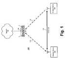
- FIG. 1is a schematic diagram illustrating an exemplary wireless system having multiple channels for communicating information between wireless devices is illustrated in accordance with at least one embodiment of the present invention.
- FIG. 2is a chart illustrating an exemplary event-based channel switch process for the wireless devices of FIG. 1 in accordance with at least one embodiment of the present invention.
- FIG. 3is a schematic diagram illustrating an exemplary wireless device in greater detail in accordance with at least one embodiment of the present invention.
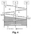
- FIG. 4is a flow diagram illustrating an exemplary method for establishing a wireless direct link on a parallel channel in accordance with at least one embodiment of the present invention.
- FIG. 5is a flow diagram illustrating an exemplary event-based channel switch process in accordance with at least one embodiment of the present invention.
- the system 100incorporates a general wireless network topology described in IEEE 802.11 and other wireless standards wherein a plurality of wireless devices 102 , 104 are associated with at least one access point 106 .
- the wireless devices 102 , 104include devices enabled to communicate wirelessly using one or more protocols.
- Such protocolsmay include, for example, the IEEE 802.11 protocols (802.11a/b/e/g/i), ANSI, Hyperlan, etc.
- wireless devicesmay include notebook (or “laptop”) computers, handheld computers, desktop computers, workstations, servers, portable digital assistants (PDAs), cellular phones, audio/visual (A/V) consoles, gaming consoles, televisions or other displays, etc.
- the system 100may include, for example, a multimedia system having one or more displays, audio/video components (e.g., a digital video disc (DVD) player or a compact disc (CD) player), sound systems, video game consoles, and the like, where each of these components may be wirelessly connected to a central console acting in the capacity of the access point 106 .
- DVDdigital video disc
- CDcompact disc
- the access point 106may be connected to an infrastructure network 108 or other network, such as, for example, the Internet, a local area network (LAN), a wide area network (WAN), and the like.
- wireless devices 102 , 104may communicate with one or more networked devices on an infrastructure network via the access point 106 .
- the wireless devices 102 , 104may communicate with each other via conventional wireless links 112 , 114 with the access point 106 or, as discussed in greater detail below, via a wireless direct link 110 between the wireless devices 102 , 104 and optionally other wireless devices. Exemplary techniques for establishing and maintaining a wireless direct link are described below and in U.S. patent application Ser. No. 60/515,701, and U.S. patent application Ser. No. 60/388,569 the entirety of which is incorporated by reference herein.
- informationis communicated between wireless devices via an access point.
- a transmitting wireless devicetransmits the information to the access point on a base channel.
- the access pointthen processes the information, such as by changing the headers of one or more frames representing the information, and forwards the information to the receiving wireless device on the base channel.
- This use of the access point as the intermediaryresults in a delay in the overall transmission time for the information, as well as crowds the base channel because two transmissions take place, rather than one.
- these transmissionsmay have been further delayed due to congestion on the base channel by other transmitting devices.
- the distances to the access pointmay be much larger than the distance between the communicating devices, which allows the communicating devices to use much higher data rates on direct communications.
- the present inventionprovides techniques for enabling wireless devices to communicate information directly without use of the access point, while still permitting the transfer of information from the access point to the wireless devices, and vice versa.
- conventional wireless links 112 , 114 between the access point 106 and the wireless devices 102 , 104may be used to initiate, establish and maintain a wireless direct link 110 between the wireless devices 102 , 104 .
- the wireless direct link 110preferably is shifted to a parallel wireless channel (i.e., separate from the base channel) so that the transmission of information via the direct link 110 is not significantly impaired by traffic on the base channel, and vice versa.
- the wireless devices 102 , 104may be configured to switch back to the base channel or other wireless channel to receive buffered downlink information or peer-to-peer information from the access point 106 or to transmit uplink information or peer-to-peer information to the access point 106 , for example.
- the switch between the parallel channel and the base channelmay occur in anticipation of a predetermined event, such as the periodic transmission of a delivery traffic indication map (DTIM) beacon frame by the access point 106 , or the switch from the parallel channel to the base channel, or vice versa, may be initiated by either of the wireless devices 102 , 104 .
- DTIMdelivery traffic indication map
- a chart 200 depicting an exemplary event-based channel switching processis illustrated in accordance with at least one embodiment of the present invention.
- the ordinate 202 of the chart 200represents time, whereas the abscissa 204 represents at least a portion of the frequency bandwidth in which the system 100 operates.
- base channel 206represents the wireless channel used by the access point 106 to communicate with the wireless devices 102 , 104 , and vice versa.
- Parallel channel 208represents a channel used by wireless devices 102 , 104 , to shift wireless direct link 110 to.
- transmission period 210may represent a direct link handshake period conducted on the base channel 206 to initiate and establish the direct link 110 on the parallel channel 208 for direct transmission of information between the wireless devices.
- An exemplary process for initiating and establishing a direct link 110 on a parallel channelis described in greater detail below with reference to FIG. 4 .
- the direct link 110may be established on parallel channel 208 for any of a variety of reasons, such as to reduce bandwidth congestion by using multiple channels to transmit information or to reduce latency in the transmission of information between the wireless devices 102 , 104 .
- the wireless devices 102 , 104switch to parallel channel 208 at or around time t 1 .
- the subsequent transmission period 212may represent a time period wherein information may be communicated between the wireless devices 102 , 104 via the direct link 110 on parallel channel 208 .
- the wireless devices 102 and 104transmit a frame to the access point with the PM bit set, to indicate to the access point that they cannot be reached.
- the nodesare on the parallel channel and are most likely not in power save, but there is no difference from the viewpoint of the access point because the wireless nodes cannot be reached in either case.
- the access pointwill buffer traffic for these nodes in separate power save queues, for later delivery.
- the wireless devices 102 , 104may directly communicate information via the direct link 110 on parallel channel 208 , the wireless devices 102 , 104 may need to return to the base channel 206 or another channel on a periodic basis in order to receive information from the access point 106 or other wireless device and/or to provide uplink information to the access point 106 or peer wireless devices.
- the wireless devices 102 , 104may be unable to receive information from the access point 106 while their transceivers are tuned to the parallel channel 208 during transmission period 212 .
- the access point 106may buffer information intended for the wireless devices 102 , 104 during the transmission period 212 .
- access pointstypically periodically transmit information that indicates that the access point has buffered information for one or more wireless devices associated with the access point.
- IEEE 802.11provides for the periodic transmission of a delivery traffic indication map (DTIM) beacon frame every DTIM period or at a target beacon transmission time (TBTT).
- DTIMdelivery traffic indication map
- TBTTtarget beacon transmission time
- wireless devices 102 , 104switch back to the base channel 206 in anticipation of a predetermined event 220 (occurring, for example, at time t 2 ), where the predetermined event 220 may include, for example: the transmission of buffered information, broadcast and/or multicast information by the access point 106 on the base channel 206 ; the transmission of an indication of buffered information by the access point 106 , such as, for example, a DTIM beacon frame; and the like.
- the wireless devices 102 , 104may use the indication of buffered information to determine whether they have information buffered at the access point 106 and then may request this information from the access point 106 using, for example, a Power Save (PS)-Poll frame.
- PSPower Save
- the transmission period 214may represent the transmission of multicast, broadcast, and buffered unicast information from the access point 106 to the wireless devices 102 , 104 , the transmission of uplink information from the wireless devices 102 , 104 to the access point 106 , the transmission of peer-to-peer information between the wireless devices 102 , 104 and other wireless devices, and the like.
- the wireless devices 102 , 104may switch back to parallel channel 208 and continue communicating information directly via the direct link 110 during transmission period 216 .
- the wireless devices 102 , 104may initiate, establish and use a wireless direct link on a different channel.
- the wireless devices 102 , 104may switch back to the base channel 206 in anticipation of another predetermined event 222 , e.g., the transmission of another DTIM map, at or around time t 4 .
- information between the access point 106 , the wireless devices 102 , 104 and/or other wireless devicesmay be communicated as described above during transmission period 218 .
- the process of switching between channels to alternatively transmit information over a direct link on one channel and communicate with the access point 106 or other wireless device on another channelmay continue for any number of cycles as appropriate.
- the direct linkcan always be used, irrespective of whether the wireless devices 102 and 104 reside on the parallel channel or on the base channel.
- wireless devices 102 , 104illustrated as wireless device 302
- exemplary methods 400 and 500 of its operationare illustrated in accordance with at least one embodiment of the present invention. Although certain actions are attributed to either wireless device 102 or wireless device 104 for ease of reference, those skilled in the art will appreciate that some or all of these actions may be performed by either wireless device 102 or wireless device 104 .
- the wireless device 302(representative of either wireless device 102 or 104 ) includes at least a transceiver 304 for transmitting and/or receiving signals representing information, one or more processors 306 and protocol stacks 308 for processing and otherwise preparing information for transmission via the transceiver 304 , as well as for processing information received via the transceiver 304 .
- the wireless device 302further may include a multiple channel direct link (MCDL) module 310 for initiating, establishing, and maintaining a one or more wireless direct links on one or more channels, communicating information via the one or more wireless direct links, switching between channels as appropriate, and other various actions described in detail herein.
- MCDLmultiple channel direct link
- the MCDL module 310may be implemented as software, hardware, firmware, or a combination thereof. To illustrate, the MCDL module 310 may be implemented as a software component of the protocol stack 308 , as a separate software program or module executed by the processor 306 , or as a software or hardware component implemented as part of the transceiver 304 .
- one of the wireless devices 102 , 104may transmit a setup request frame to the access point 106 on the base channel for forwarding to the wireless device 104 at step 402 , where the setup request frame represents an invitation or proposal to establish a direct link on another channel.
- the setup request framemay include a channel information element (CIE) (e.g., in the payload of the frame), where the CIE may include one or more indicators associated with a proposed channel, such as, for example, the center frequency and channel width of the proposed channel or a low frequency and a high frequency of the proposed channel.
- CIEchannel information element
- the proposed channelmay be selected at random, or, in one embodiment, the wireless device 102 may scan one or more potential channels for traffic and select a channel having relatively little or no traffic as the proposed channel.
- the setup requestmay be encapsulated inside a regular data frame, using LLC encapsulation. This method is described in more detail in U.S. patent application Ser. No. 60/515,701, which has been referenced before. Security credentials may also be included inside the setup frames. Due to the encapsulation in a regular data frame, any access point will forward the frame to the ultimate destination without processing the data portion, irrespective of whether the access point knows about this protocol or not. The LLC encapsulation effectively creates a transparent tunnel through the access point.
- the access point 106may process the setup request frame as necessary and forward the setup request frame to the wireless device 104 at step 404 . Access points will usually forward this data frame without additional processing of the payload.
- the wireless device 104may consider the proposal to establish a direct link on the proposed channel. If acceptable, the wireless device 104 may transmit an affirmative setup response frame to the access point 106 on the base channel for forwarding to the wireless device 102 at step 406 . If the proposal to establish a direct link is acceptable but the proposed channel is not (because, for example, the wireless device 104 cannot operate at the proposed frequency), the wireless device 104 may transmit a conditional setup response frame to the access point 106 on the base channel for forwarding to the wireless device 102 .
- the conditional setup response framemay include a proposal for an alternate channel for consideration by the wireless device 102 .
- the wireless device 104may transmit a negative setup response frame to the wireless device 102 indicating that the wireless device 104 has declined to participate in a direct link with the wireless device 102 .
- the wireless device 102may attempt to set up a direct link 110 on the base channel or it may cease attempts to establish a direct link 110 with the wireless device 104 .
- the setup response frameincludes an agreed/denied/conditional field that may be used to indicate whether the setup response is affirmative, negative or conditional. If the responding device does not support direct link, it may not recognize the multi channel capability (i.e. the CIE element), and it may respond with a response message that does not include a multi channel capability element (i.e. the CIE element). In this way, a direct link may still be set up, but possibly without the option of being shifted to another channel.
- the multi channel capabilityi.e. the CIE element
- the setup response framemay further include an indication that the wireless device 104 is entering a sleep mode or power-saving mode whereby the access point 106 is to buffer all information intended for the wireless device 104 until the access point 106 is polled for the buffered information.
- the power-saving mode indicatormay include, for example, a power management (PM) bit set or cleared in the header of the setup response frame.
- the access point 106Upon receipt of the setup response frame, the access point 106 preferably enacts the buffering mechanism if so directed by the power-saving mode indicator and forwards the setup response frame to the wireless device 102 at step 408 .
- the wireless device 102may transmit a setup confirm frame to the access point 106 for forwarding at step 410 . If the response is conditional upon acceptance of the use of the channel proposed by the wireless device 104 , the wireless device 102 may determine whether this proposed channel is acceptable. If so, the wireless device 102 may transmit the setup confirm frame at step 410 . If the response is negative, the wireless device 102 preferably ceases any attempts to establish a direct link.
- the setup confirmation framemay include an indication (e.g., a set PM bit) that the wireless device 102 is entering a sleep mode or power-saving mode and information intended for the wireless device 102 should be buffered at the access point 106 .
- the access point 106may activate the buffering mechanism and forward the setup confirm frame to the wireless device 104 on the base channel at step 412 .
- the wireless device 102Upon transmitting the setup confirm frame at step 410 , in one embodiment, the wireless device 102 switches its transceiver 304 to the agreed-to channel and waits for the arrival of the wireless device 104 at step 414 . Likewise, the wireless device 104 switches its transceiver 304 to the proposed channel upon receipt of the setup confirm frame at step 416 . To announce its presence on the proposed channel, the wireless device 104 may transmit an announcement frame on the proposed channel directly to the wireless device 102 at step 418 . At this point, the direct link 110 may be considered to be established and the wireless devices 102 , 104 may initiate the communication of information on the parallel channel via the direct link 110 at step 420 .
- devices 102 and/or 104do not set the PM bit on the direct link handshake frames, but separate frames with the PM bit set are transmitted instead. These frames may be Null frames or regular data frames. Shifting the direct link to another channel is postponed until after the transmission of these separate PM frames. Shifting the direct link may be accomplished by a permanent or temporary channel switch, which are discussed in detail below.
- the direct link handshakemay still include a multi channel capability or a set of supported channels to which the direct link could be transferred.
- the wireless device 102may use this waiting period to scan the parallel channel to listen for traffic on the parallel channel.
- the arrival of wireless device 104may be announced by the transmission of a first frame, which opens the direct link on the new channel.
- the wireless device 102may suspend or cancel the direct link by transmitting, for example, a slow resumption mode (SRM) frame or a fast resumption mode (FRM) frame, or the wireless device 104 may transmit a channel switch request to the wireless device 104 once the wireless device 104 has switched to the parallel channel, where the channel switch request represents a proposal to switch the direct link to another parallel channel. Permanent and temporary channel switch requests are discussed in detail below.
- SRMslow resumption mode
- FPMfast resumption mode
- peer-to-peer traffic through the access pointis preferably is temporarily suspended to avoid any reordering of frames waiting at the access point 106 .
- the wireless devices 102 , 104may use a power-saving mode indicator, such as, for example, the PM bit, to notify the access point 106 that the devices 102 , 104 are entering a power-save mode and therefore directing the access point 106 to buffer downlink data until it is requested from the wireless devices via, for example, power mode-poll (PM-Poll) frames as described by IEEE 802.11.
- PM-Pollpower mode-poll
- the method 500initiates at steps 502 A and 502 B wherein the wireless devices 102 , 104 switch from the parallel channel (established using method 400 of FIG. 4 , for example) to the base channel of the access point 106 in anticipation of, or in preparation for, a predetermined event.
- the predetermined eventincludes the transmission of a DTIM beacon frame at steps 504 A, 504 B.
- DTIM beacon framestypically are transmitted substantially periodically (i.e., every DTIM beacon interval) and include a bitmap that indicates which wireless devices have information buffered at the access point 106 .
- the wireless devices 102 , 104may switch to the base channel to receive the DTIM beacon frames so that the wireless devices 102 , 104 may determine whether there is information waiting for them at the access point 106 .
- the wireless devices 102 , 104preferably switch to the base channel slightly before the DTIM beacon is scheduled to be transmitted to help ensure that the wireless devices 102 , 104 are switched to the base channel in time to receive the DTIM beacon frame.
- the wireless devices 102 , 104may remain on the base channel after receiving the DTIM beacon frame the transmission of broadcast and multicast information (steps 506 A and 506 B) typically follows the transmission of a DTIM beacon frame.
- the wireless devices 102 , 104are configured to switch back to the parallel channel at steps 508 A and 508 B after receiving the DTIM beacon frame and any multicast/broadcast information. If one or both of the wireless devices 102 , 104 determine that they have buffered information at the access point 106 using the DTIM beacon frame, the wireless device (device 102 in this example) may transmit a permanent channel switch (PCS) request frame on the parallel channel with a request to switch back to the parallel channel to the other wireless device at step 510 .
- PCSpermanent channel switch
- the PCS request framerepresents a request to switch to a proposed channel and includes one or more indicators of the proposed channel, such as, for example, the center frequency and channel width or a low frequency and a high frequency for the proposed channel.
- the receiving wireless devicesends an affirmative PCS response frame on the parallel channel at step 512 .
- the receiving wireless devicemay transmit a conditional PCS response frame having an alternate proposed channel or a negative PCS response frame if no alternate channel is acceptable. If conditional, the wireless devices 102 , 104 negotiate an channel acceptable to both wireless devices 102 , 104 or if negative, the wireless devices 102 , 104 may cease communicating on the parallel channel and return to the base channel.
- a parallel channelmay have been agreed upon during the setup phase and the PCS request may not contain an explicit channel information element.
- the receipt of a PCS requestsimply indicates in that case that a switch to the other channel is requested, i.e. the parallel channel if transmitted on the base channel and the base cannel if transmitted on the parallel channel.
- the wireless devices 102 , 104may stay on the base channel after the end of the broadcast and multicast transmissions, while returning to the parallel channel is signaled by an explicit PCS request.
- the PCS request and response framespreferably are transmitted as quality-of-service (QoS) frames having a piggyback contention-free-acknowledgement (CF-Ack) as this type of frame typically requires only a single transmission operation (TXOP).
- QoSquality-of-service
- CF-Ackpiggyback contention-free-acknowledgement
- TXOPtransmission operation
- suitable piggyback framesthat may be implemented as PCS request and/or response frames are described in detail in U.S. patent application Ser. No. 10/880,367 filed concurrently herewith and entitled “Link Margin Notification Using Return Frame.”
- Other frame formats, such as conventional data frames,may be used without departing from the spirit or the scope of the present invention.
- the wireless devices 102 , 104Upon agreeing to a proposed switch to the base channel, the wireless devices 102 , 104 make the channel switch at steps 514 A, 514 B. One or both of the wireless devices 102 , 104 then may request and receive buffered information from the access point 106 , provide uplink information to the access point 106 , and/or communicate information with peer wireless devices via the base channel.
- the wireless device 102may use a reverse polling technique by transmitting a PS-Poll frame (e.g., a QoS+CF+Poll frame) to the access point 106 at step 516 , where the PS-Poll frame represents a request for buffered information and an indication (e.g., a clearing of the PM bit) that the wireless device 102 has exited the power-saving mode.
- a PS-Poll framee.g., a QoS+CF+Poll frame
- the access point 106may transmit buffered downlink information to the wireless device 102 at step 518 .
- the wireless device 102may transmit another frame, such as a null frame, to the access point 106 at step 520 , where the frame includes an indicator that the wireless device 102 is entering the power-saving mode so that the access point 106 may buffer any downlink information intended for the wireless device 102 .
- Uplink information and peer-to-peer informationmay be transmitted from the wireless devices 102 , 104 in a similar manner.
- one of the wireless devicesmay transmit a PCS request frame on the base channel at step 522 , where the PCS request frame may include an indication of the proposed channel to which the wireless devices 102 , 104 are to switch.
- the wireless devices 102 , 104switch to the same parallel channel as before.
- it may be appropriate to switch to another channelbecause, for example, the original parallel channel has become congested with traffic from other wireless devices or significant interference as appeared at one or more frequencies of the original parallel channel.
- the wireless device 104may transmit an affirmative or conditional PCS response frame to the wireless device 102 on the base channel at step 524 .
- the wireless devicesswitch to the proposed parallel channel and recommence the communication of information between the wireless devices 102 , 104 via the direct link 110 on the parallel channel at step 528 .
- the wireless devices 102 , 104may utilize a temporary channel switch (TCS) sequence to temporarily move the direct link 110 to another channel.
- TCStemporary channel switch
- the TCS sequencetypically includes a TCS request frame that may include a CIE and a timing synchronization function (TSF) to indicate the time at which the direct link 110 is scheduled to return to the current channel.
- TCS sequencealso may include a TCS response frame that includes an agreed/denied/conditional field similar to the field used for the PCS response frame. If the responding wireless device can not leave the current channel, for instance if it is not yet in a power-save mode with the access point 106 , it may set the denied field inside the TCS response frame. Otherwise, if the responding wireless device is ready to move to the proposed channel, it may set the agreed field inside the TCS response frame.
- the TCS sequencealso may be used to temporarily move the direct link 110 to the base channel for the exchange of information with the access point 106 (e.g., buffered information) or with peer devices.
- the direct link 110preferably remains active during this time, so that information can be exchanged via the direct link 110 on the base channel as well.
- Devices 102 and 104should not leave the power save state with the access point during this temporary stay on the base channel (for instance, by transmitting a frame to the access point with the PM bit reset), because it can not be ensured that they will be able to re-enter the power save state prior to the scheduled departure to the parallel channel with TCS.
- multiple deviceseach may establish a direct link with a single device.
- the presence of multiple direct linksraises the issue of selecting a common parallel channel for the multiple direct links.
- the wireless device acting as the “hub” for the multiple peer devicesmay identify a suitable parallel channel that the multiple direct links may use by, for example, proposing a parallel channel currently in use, by scanning one or more other parallel channels, or by picking a channel at random.
- Another issue raised by multiple direct linksincludes channel switching.
- a device having multiple direct linkswants to perform a channel switch, it preferably transmits a PCS request frame to each of the other direct link peer devices before switching to the proposed channel.
- Yet another issueincludes the implementation of power saving or the sleep mode.
- this issuemay be addressed by assuming that the traffic pattern has a star topology, so that there is a central node that communicates with the peripheral nodes, but the peripheral nodes do not communicate with each other.
- the central nodemay be treated as a constantly awake node (CAN) that acts as a surrogate access point by buffering information for all of the peripheral nodes, while maintaining a client association with the real access point at the same time.
- the peripheral nodesfind can find the central node through its beacon transmissions and may associate with it instead of with the access point.
- the peripheral nodesthen may use reverse polling to retrieve buffered information, as described above.
- This solutionis suited for applications like gaming and multimedia, where a single central node maintains connections with several remote nodes, like game controllers or actuators, respectively.
Landscapes
- Engineering & Computer Science (AREA)
- Computer Networks & Wireless Communication (AREA)
- Signal Processing (AREA)
- Mobile Radio Communication Systems (AREA)
Abstract
Description
Claims (36)
Priority Applications (5)
| Application Number | Priority Date | Filing Date | Title |
|---|---|---|---|
| US10/880,370US7251235B2 (en) | 2002-06-12 | 2004-06-30 | Event-based multichannel direct link |
| PCT/US2004/033487WO2005046134A1 (en) | 2003-10-31 | 2004-10-13 | Link margin notification using return frame |
| EP04794757.7AEP1678881B8 (en) | 2003-10-31 | 2004-10-13 | Link margin notification using return frame |
| US12/460,974USRE43127E1 (en) | 2002-06-12 | 2009-07-27 | Event-based multichannel direct link |
| US13/351,588USRE45212E1 (en) | 2002-06-12 | 2012-01-17 | Event-based multichannel direct link |
Applications Claiming Priority (4)
| Application Number | Priority Date | Filing Date | Title |
|---|---|---|---|
| US38856902P | 2002-06-12 | 2002-06-12 | |
| US10/353,391US6791962B2 (en) | 2002-06-12 | 2003-01-29 | Direct link protocol in wireless local area networks |
| US51570103P | 2003-10-31 | 2003-10-31 | |
| US10/880,370US7251235B2 (en) | 2002-06-12 | 2004-06-30 | Event-based multichannel direct link |
Related Parent Applications (2)
| Application Number | Title | Priority Date | Filing Date |
|---|---|---|---|
| US10/353,391Continuation-In-PartUS6791962B2 (en) | 2002-06-12 | 2003-01-29 | Direct link protocol in wireless local area networks |
| US12/460,974ContinuationUSRE43127E1 (en) | 2002-06-12 | 2009-07-27 | Event-based multichannel direct link |
Related Child Applications (2)
| Application Number | Title | Priority Date | Filing Date |
|---|---|---|---|
| US12/460,974ReissueUSRE43127E1 (en) | 2002-06-12 | 2009-07-27 | Event-based multichannel direct link |
| US13/351,588ReissueUSRE45212E1 (en) | 2002-06-12 | 2012-01-17 | Event-based multichannel direct link |
Publications (2)
| Publication Number | Publication Date |
|---|---|
| US20050036469A1 US20050036469A1 (en) | 2005-02-17 |
| US7251235B2true US7251235B2 (en) | 2007-07-31 |
Family
ID=46302279
Family Applications (1)
| Application Number | Title | Priority Date | Filing Date |
|---|---|---|---|
| US10/880,370CeasedUS7251235B2 (en) | 2002-06-12 | 2004-06-30 | Event-based multichannel direct link |
Country Status (1)
| Country | Link |
|---|---|
| US (1) | US7251235B2 (en) |
Cited By (66)
| Publication number | Priority date | Publication date | Assignee | Title |
|---|---|---|---|---|
| US20040264504A1 (en)* | 2003-06-24 | 2004-12-30 | Samsung Electronics Co., Ltd. | Apparatus and method for enhancing transfer rate using a direct link protocol (DLP) and multiple channels in a wireless local area network (LAN) using a distributed coordination function (DCF) |
| US20050030976A1 (en)* | 2002-06-12 | 2005-02-10 | Globespan Virata Incorporated | Link margin notification using return frame |
| US20050122927A1 (en)* | 2003-01-29 | 2005-06-09 | Conexant, Inc. | Power management for wireless direct link |
| US20050130634A1 (en)* | 2003-10-31 | 2005-06-16 | Globespanvirata, Inc. | Location awareness in wireless networks |
| US20050135305A1 (en)* | 2002-06-12 | 2005-06-23 | Globespanvirata, Inc. | Automatic peer discovery |
| US20050226183A1 (en)* | 2004-04-09 | 2005-10-13 | Sitarama Penumetsa | Systems and methods for implementing an enhanced multi-channel direct link protocol between stations in a wireless LAN environment |
| US20060040701A1 (en)* | 2004-08-18 | 2006-02-23 | Staccato Communications, Inc. | Beacon group merging |
| US20060087995A1 (en)* | 2004-10-27 | 2006-04-27 | Hidetada Nago | Wireless communication apparatus, communication system and wireless communication method |
| US20060116919A1 (en)* | 2004-11-29 | 2006-06-01 | Microsoft Corporation | Efficient and flexible business modeling based upon structured business capabilities |
| US20070078000A1 (en)* | 2005-10-04 | 2007-04-05 | Pico Mobile Networks, Inc. | Distributed wireless gaming |
| US20070214492A1 (en)* | 2006-03-07 | 2007-09-13 | Marvell International Ltd. | Personal lifestyle device |
| US20070280180A1 (en)* | 2004-06-08 | 2007-12-06 | Koninklijke Philips Electronics, N.V. | Wireless Communication System, Wireless Communication Device for Use as a Station in a Wireless Communication System, a Method of Communication Within a Wireless Communication System |
| US20070286419A1 (en)* | 2006-06-07 | 2007-12-13 | Dmitri Varsanofiev | Efficient Video Delivery in Legacy 802.11 Infrastructure Enviroments |
| US20080032625A1 (en)* | 2006-07-19 | 2008-02-07 | David Cheung | Deviating from a transmission map to communicate in a wireless network |
| US20080037444A1 (en)* | 2006-08-08 | 2008-02-14 | Marvell Semiconductor, Inc. | Ad-hoc simple configuration |
| US20080146253A1 (en)* | 2006-12-19 | 2008-06-19 | Conexant Systems, Inc. | Systems and methods for retrieving buffered data from an access point |
| US20080225768A1 (en)* | 2007-03-13 | 2008-09-18 | Conexant Systems, Inc. | Systems and Methods for Indicating Buffered Data at an Access Point Using a Traffic Indication Map Broadcast |
| US20080273700A1 (en)* | 2007-05-04 | 2008-11-06 | Conexant Systems, Inc. | Systems and Methods For Multicast Retransmission over a Secure Wireless LAN |
| US20080298290A1 (en)* | 2007-05-31 | 2008-12-04 | Conexant Systems, Inc. | Systems and Methods for Indicating Buffered Data at an Access Point with Efficient Beacon Handling |
| US20090011834A1 (en)* | 2007-07-03 | 2009-01-08 | Kapil Chhabra | Location aware ad-hoc gaming |
| US20090010191A1 (en)* | 2007-07-05 | 2009-01-08 | Conexant Systems, Inc. | Systems and Methods for Indicating Buffered Data at an Access Point Using an Embedded Traffic Indication Map |
| US20090073945A1 (en)* | 2007-09-18 | 2009-03-19 | Lg Electronics Inc. | Direct link setup procedure in tunneled direct link setup wireless network and station supporting the procedure |
| US20090156224A1 (en)* | 2005-09-15 | 2009-06-18 | Pioneer Corporation | Wireless communication system base station apparatus, wireless communication system terminal apparatus, wireless communication system, and method for canceling direct link mode |
| US20090274135A1 (en)* | 2008-05-01 | 2009-11-05 | Yongho Seok | Direct link setup method in tunneled direct link setup wireless network and station supporting the method |
| KR100930795B1 (en) | 2008-03-03 | 2009-12-09 | 고려대학교 산학협력단 | Station-to-Station Direct Communication in Infrastructure WLAN |
| US20090325571A1 (en)* | 2007-09-05 | 2009-12-31 | Conexant Systems Inc. | Scanning Threshold |
| US20090323611A1 (en)* | 2008-06-26 | 2009-12-31 | Samsung Electronics Co., Ltd. | System and method for priority driven contention scheme for supporting enhanced QoS in a wireless communication network |
| US20100002639A1 (en)* | 2008-07-02 | 2010-01-07 | Samsung Electronics Co., Ltd. | System and method for reservation of disjoint time intervals in wireless local area networks |
| US20100054214A1 (en)* | 2008-09-02 | 2010-03-04 | Ntt Docomo, Inc. | Access point, wireless communication station, wireless communication system and wireless communication method |
| US20100165896A1 (en)* | 2008-12-31 | 2010-07-01 | Michelle Xiaohong Gong | Power saving in peer-to-peer communication devices |
| US20100202335A1 (en)* | 2007-06-06 | 2010-08-12 | Claudio Borean | Method for managing the transfer of information packets across a wireless and routing nodes implementing it |
| US7884615B1 (en) | 2002-06-07 | 2011-02-08 | Marvell International Ltd. | Cable tester |
| US7889686B1 (en) | 2006-11-21 | 2011-02-15 | Picomobile Networks, Inc. | Seamless switching of media streams between different networks |
| US20110051678A1 (en)* | 2009-09-02 | 2011-03-03 | Sung-Chien Tang | Channel Status Determination Method and Related Wireless Local Area Network System and Direct Link Setup Method |
| US7906973B1 (en) | 2006-06-09 | 2011-03-15 | Marvell International Ltd. | Cable tester |
| US20110082940A1 (en)* | 2009-10-02 | 2011-04-07 | Michael Peter Montemurro | Methods and apparatus to establish peer-to-peer communications |
| US20110082939A1 (en)* | 2009-10-02 | 2011-04-07 | Michael Peter Montemurro | Methods and apparatus to proxy discovery and negotiations between network entities to establish peer-to-peer communications |
| US7944897B2 (en) | 2005-11-03 | 2011-05-17 | Samsung Electronics Co., Ltd. | Method and system for addressing channel access unfairness in IEEE 802.11n wireless networks |
| US7961756B1 (en) | 2006-11-21 | 2011-06-14 | Picomobile Networks, Inc. | Integrated multimedia system |
| US7970384B1 (en) | 2006-11-21 | 2011-06-28 | Picomobile Networks, Inc. | Active phone book enhancements |
| US7978699B1 (en) | 2006-11-21 | 2011-07-12 | Picomobile Networks, Inc. | Protocol compression with synchronized sequence numbers |
| US8000719B1 (en) | 2006-11-21 | 2011-08-16 | Pico Mobile Networks, Inc. | Multi-mode location services |
| US20110228755A1 (en)* | 2008-10-15 | 2011-09-22 | Lg Electronics Inc. | Direct link setup method in tunneled direct link setup (tdls) wireless network |
| US8050360B2 (en) | 2002-06-12 | 2011-11-01 | Intellectual Ventures I Llc | Direct link relay in a wireless network |
| USRE43127E1 (en) | 2002-06-12 | 2012-01-24 | Intellectual Ventures I Llc | Event-based multichannel direct link |
| US20120120892A1 (en)* | 2010-11-16 | 2012-05-17 | Interdigital Patent Holdings, Inc. | Method and apparatus for wireless direct link operation |
| US20120195244A1 (en)* | 2006-11-07 | 2012-08-02 | Menzo Wentink | Systems and methods for management of wireless clients |
| US8257177B1 (en) | 2005-10-04 | 2012-09-04 | PICO Mobile Networks, Inc | Proximity based games for mobile communication devices |
| US8279884B1 (en) | 2006-11-21 | 2012-10-02 | Pico Mobile Networks, Inc. | Integrated adaptive jitter buffer |
| US8379528B1 (en)* | 2010-10-15 | 2013-02-19 | Sprint Communications Company L.P. | Transfer of messages to user devices of a wireless local area network access point |
| US8411662B1 (en) | 2005-10-04 | 2013-04-02 | Pico Mobile Networks, Inc. | Beacon based proximity services |
| US8817722B2 (en) | 2011-06-07 | 2014-08-26 | Qualcomm Incorporated | Preemptive direct link channel switching |
| US8891492B1 (en) | 2006-10-16 | 2014-11-18 | Marvell International Ltd. | Power save mechanisms for dynamic ad-hoc networks |
| US8918051B1 (en) | 2007-06-18 | 2014-12-23 | Marvell International Ltd. | Method and apparatus for performing a handoff of a data communication session from one network to another network |
| US8917743B2 (en) | 2010-10-06 | 2014-12-23 | Samsung Electronics Co., Ltd. | Method and system for enhanced contention avoidance in multi-user multiple-input-multiple-output wireless networks |
| US8953578B2 (en) | 2010-06-23 | 2015-02-10 | Samsung Electronics Co., Ltd. | Method and system for contention avoidance in multi-user multiple-input-multiple-output wireless networks |
| US9232543B2 (en) | 2010-07-07 | 2016-01-05 | Samsung Electronics Co., Ltd. | Method and system for communication in multi-user multiple-input-multiple-output wireless networks |
| US9232502B2 (en) | 2012-10-31 | 2016-01-05 | Samsung Electronics Co., Ltd. | Method and system for uplink multi-user multiple-input-multiple-output communication in wireless networks |
| US9295074B2 (en) | 2013-09-10 | 2016-03-22 | Samsung Electronics Co., Ltd. | Acknowledgement, error recovery and backoff operation of uplink multi-user multiple-input-multiple-output communication in wireless networks |
| US9308455B1 (en) | 2006-10-25 | 2016-04-12 | Marvell International Ltd. | System and method for gaming in an ad-hoc network |
| US9332571B2 (en) | 2010-04-19 | 2016-05-03 | Samsung Electronics Co., Ltd. | Method and system for multi-user transmit opportunity for multi-user multiple-input-multiple-output wireless networks |
| US9380401B1 (en) | 2010-02-03 | 2016-06-28 | Marvell International Ltd. | Signaling schemes allowing discovery of network devices capable of operating in multiple network modes |
| US9419752B2 (en) | 2013-03-15 | 2016-08-16 | Samsung Electronics Co., Ltd. | Transmission opportunity operation of uplink multi-user multiple-input-multiple-output communication in wireless networks |
| US9432872B2 (en) | 2013-11-21 | 2016-08-30 | Qualcomm Incorporated | Systems and methods for direct link communication with multi-channel concurrency |
| US9444874B2 (en) | 2006-10-16 | 2016-09-13 | Marvell International Ltd. | Automatic Ad-Hoc network creation and coalescing using WPS |
| US10880702B1 (en) | 2019-06-04 | 2020-12-29 | Sprint Communications Company L.P. | Data communications for user applications that are executing in a wireless user device |
Families Citing this family (57)
| Publication number | Priority date | Publication date | Assignee | Title |
|---|---|---|---|---|
| US20040156367A1 (en)* | 2003-02-11 | 2004-08-12 | Magis Networks, Inc. | Hierarchically distributed scheduling apparatus and method |
| KR100526185B1 (en)* | 2003-08-14 | 2005-11-03 | 삼성전자주식회사 | Method And Apparatus for Enhancing Transfer Rate Using DLP And Multi-Channel In Wireless Lan Using PCF And DCF |
| TWI262680B (en)* | 2004-11-23 | 2006-09-21 | Inst Information Industry | Improved direct link transmission method and system for wireless LAN |
| US20060153085A1 (en)* | 2004-12-27 | 2006-07-13 | Willins Bruce A | Method and system for recovery from access point infrastructure link failures |
| US20060166683A1 (en)* | 2005-01-26 | 2006-07-27 | Sharma Sanjeev K | Method and system for use of the same time slot of the same channel by multiple pairs of devices via a direct link protocol |
| US20070097934A1 (en) | 2005-11-03 | 2007-05-03 | Jesse Walker | Method and system of secured direct link set-up (DLS) for wireless networks |
| US8077683B2 (en)* | 2005-11-03 | 2011-12-13 | Interdigital Technology Corporation | Method and system for performing peer-to-peer communication between stations within a basic service set |
| EP1952571A2 (en)* | 2005-11-04 | 2008-08-06 | Nokia Corporation | Method, wireless local area network(wlan),node and apparatus for multicast and/or broadcast acknowledgements |
| JP4868835B2 (en)* | 2005-11-28 | 2012-02-01 | キヤノン株式会社 | Communication path setting method, communication apparatus, and program |
| JP4506658B2 (en)* | 2005-11-30 | 2010-07-21 | ソニー株式会社 | Wireless communication system, communication apparatus, setting information providing method, setting information obtaining method, and computer program |
| US7734292B2 (en)* | 2005-12-07 | 2010-06-08 | Electronics And Telecommunications Research Institute | Terminal supporting peer-to-peer communication, and communication and billing methods based on the same |
| JP4911970B2 (en)* | 2005-12-20 | 2012-04-04 | キヤノン株式会社 | Base station control method and base station |
| KR101353404B1 (en)* | 2006-01-17 | 2014-01-20 | 톰슨 라이센싱 | Gateway for receiving digital television broadcasting services, terminal and corresponding methods |
| WO2007124055A2 (en)* | 2006-04-21 | 2007-11-01 | Interdigital Technology Corporation | Wireless communication method and apparatus for providing network advice to mobile stations |
| US7656849B1 (en)* | 2006-05-31 | 2010-02-02 | Qurio Holdings, Inc. | System and method for bypassing an access point in a local area network for P2P data transfers |
| US8102863B1 (en) | 2006-06-27 | 2012-01-24 | Qurio Holdings, Inc. | High-speed WAN to wireless LAN gateway |
| US7865196B2 (en)* | 2006-06-30 | 2011-01-04 | Intel Corporation | Device, system, and method of coordinating wireless connections |
| TWI316374B (en)* | 2006-07-21 | 2009-10-21 | Hon Hai Prec Ind Co Ltd | System and method for saving power of station |
| KR100772417B1 (en)* | 2006-09-26 | 2007-11-01 | 삼성전자주식회사 | Wireless network communication method and device using direct link |
| AU2007312944A1 (en)* | 2006-10-17 | 2008-04-24 | Altec Lansing Australia Pty Ltd | Configuring and connecting to a media wireless network |
| WO2008111826A1 (en)* | 2007-03-10 | 2008-09-18 | Lg Electronics Inc. | Peer power save mode in tunneled direct link setup (tdls) wireless network |
| US8005515B1 (en) | 2007-04-04 | 2011-08-23 | Marvell World Trade Ltd. | Beacon miss prevention in power save modes using timing synchronization function |
| KR20090117560A (en)* | 2008-05-09 | 2009-11-12 | 엘지전자 주식회사 | Direct Link Setup Procedure and Channel Assignment Mechanism in Multi-Channel Wireless Communication Networks |
| US8274926B2 (en)* | 2008-07-15 | 2012-09-25 | Panasonic Corporation | Control device, communication terminal, control method, and communication method |
| JP4609547B2 (en)* | 2008-08-14 | 2011-01-12 | ソニー株式会社 | Wireless communication apparatus, communication system, communication control method, and program |
| CN102187712B (en)* | 2008-10-28 | 2014-03-12 | 艾可慕株式会社 | Wireless terminal device, wireless communication method, and wireless communication system and program |
| US8270304B2 (en)* | 2008-10-31 | 2012-09-18 | Symbol Technologies, Inc. | Methods and apparatus for access point scanning in VOIP systems |
| JP4490499B2 (en)* | 2008-11-26 | 2010-06-23 | パナソニック株式会社 | Communication terminal, relay device, wireless communication system, wireless communication control method, and program |
| US20100255869A1 (en)* | 2009-04-06 | 2010-10-07 | Kapil Sood | Direct peer link establishment in wireless networks |
| US8737316B2 (en)* | 2009-05-01 | 2014-05-27 | Qualcomm Incorporated | Home agent-less MIPv6 route optimization over WAN |
| JP5613770B2 (en) | 2009-09-18 | 2014-10-29 | インターデイジタル パテント ホールディングス インコーポレイテッド | Method and apparatus for providing a network connection for peer-to-peer direct link communication |
| US20110103240A1 (en) | 2009-10-29 | 2011-05-05 | Qualcomm Incorporated | Method for forwarding in peer-to-peer wireless communications |
| US8238831B2 (en) | 2010-03-26 | 2012-08-07 | Apple Inc. | Wireless interference mitigation |
| US8805397B2 (en)* | 2010-03-26 | 2014-08-12 | Apple Inc. | Wireless interference mitigation |
| US8675529B2 (en)* | 2010-09-02 | 2014-03-18 | Texas Instruments Incorporated | Power efficient tunneled direct link setup apparatus, systems and methods |
| US10721782B2 (en)* | 2010-09-02 | 2020-07-21 | Texas Instruments Incorporated | Power efficient tunneled direct link setup apparatus, systems and methods |
| US9374767B2 (en) | 2011-03-09 | 2016-06-21 | Intel Deutschland Gmbh | Communication devices and methods for network signaling |
| US9515925B2 (en) | 2011-05-19 | 2016-12-06 | Qualcomm Incorporated | Apparatus and methods for media access control header compression |
| US9635694B2 (en) | 2011-07-25 | 2017-04-25 | Qualcomm Incorporated | Method and apparatus for tunneled direct link setup management |
| US9210731B2 (en)* | 2011-07-25 | 2015-12-08 | Qualcomm Incorporated | Direct link setup through an extended service set |
| ES2713081T3 (en)* | 2011-08-01 | 2019-05-17 | Intel Corp | Opportunistic communication device to device |
| KR101826327B1 (en)* | 2011-08-02 | 2018-02-07 | 삼성전자주식회사 | Method for generating wi-fi p2p group |
| US8982785B2 (en)* | 2011-09-08 | 2015-03-17 | Cisco Technology, Inc. | Access point assisted direct client discovery |
| KR20140001300A (en)* | 2012-06-25 | 2014-01-07 | 한국전자통신연구원 | Cellular communication system and method thereof |
| US8989807B2 (en) | 2013-02-28 | 2015-03-24 | Intel Mobile Communications GmbH | Communication terminal device, communication device, communication network server and method for controlling |
| CN104023316B (en)* | 2013-03-01 | 2017-11-17 | 华为技术有限公司 | Multicast information transmission method and apparatus |
| GB2517844B (en) | 2014-02-25 | 2015-09-09 | Cambridge Silicon Radio Ltd | Thwarting traffic analysis |
| GB2515853B (en) | 2014-02-25 | 2015-08-19 | Cambridge Silicon Radio Ltd | Latency mitigation |
| US9521192B2 (en) | 2014-10-30 | 2016-12-13 | Intel Corporation | Apparatus, system and method of communicating traffic to a plurality of peer to peer devices |
| US10051676B2 (en) | 2014-10-30 | 2018-08-14 | Intel Corporation | Apparatus, system and method of peer to peer communication |
| US11140457B1 (en)* | 2018-09-20 | 2021-10-05 | Amazon Technologies, Inc. | Network routing selections for wireless devices |
| US11323217B2 (en)* | 2019-08-29 | 2022-05-03 | Cisco Technology, Inc. | Multi-band width tone plan for OFDMA in a wireless network |
| US11314320B2 (en)* | 2020-04-28 | 2022-04-26 | Facebook Technologies, Llc | Interface between host processor and wireless processor for artificial reality |
| TWI730908B (en)* | 2020-10-07 | 2021-06-11 | 瑞昱半導體股份有限公司 | Network device and network connection method |
| CN115334602A (en)* | 2021-05-11 | 2022-11-11 | 华为技术有限公司 | Wireless communication anti-interference method, electronic equipment, chip and readable storage medium |
| WO2023113370A1 (en)* | 2021-12-14 | 2023-06-22 | 삼성전자 주식회사 | Electronic device for wireless lan communication with plurality of external apparatuses, and operation method therefor |
| EP4401502A4 (en) | 2021-12-14 | 2025-01-08 | Samsung Electronics Co., Ltd. | ELECTRONIC DEVICE FOR WIRELESS LAN COMMUNICATION WITH A PLURALITY OF EXTERNAL DEVICES AND METHOD FOR OPERATING THE ELECTRONIC DEVICE |
Citations (17)
| Publication number | Priority date | Publication date | Assignee | Title |
|---|---|---|---|---|
| US5463659A (en)* | 1994-07-05 | 1995-10-31 | At&T Ipm Corp. | Apparatus and method of configuring a cordless telephone for operating in a frequency hopping system |
| US6208627B1 (en) | 1997-12-10 | 2001-03-27 | Xircom, Inc. | Signaling and protocol for communication system with wireless trunk |
| US6360277B1 (en) | 1998-07-22 | 2002-03-19 | Crydom Corporation | Addressable intelligent relay |
| US6424820B1 (en) | 1999-04-02 | 2002-07-23 | Interval Research Corporation | Inductively coupled wireless system and method |
| US6463290B1 (en) | 1999-01-08 | 2002-10-08 | Trueposition, Inc. | Mobile-assisted network based techniques for improving accuracy of wireless location system |
| US20020168993A1 (en) | 2001-05-10 | 2002-11-14 | Koninklijke Philips Electronics N.V. | Updating path loss estimation for power control and link adaptation in IEEE 802.11h WLAN |
| US6484027B1 (en) | 1998-06-15 | 2002-11-19 | Sbc Technology Resources, Inc. | Enhanced wireless handset, including direct handset-to-handset communication mode |
| US20020172186A1 (en) | 2001-04-09 | 2002-11-21 | Peter Larsson | Instantaneous joint transmit power control and link adaptation for RTS/CTS based channel access |
| US6487180B1 (en) | 1996-10-15 | 2002-11-26 | Motorola, Inc. | Personal information system using proximity-based short-range wireless links |
| US6496694B1 (en) | 2000-01-13 | 2002-12-17 | Intel Corporation | Wireless local loop with intelligent base station |
| US6580704B1 (en)* | 1999-08-26 | 2003-06-17 | Nokia Corporation | Direct mode communication method between two mobile terminals in access point controlled wireless LAN systems |
| DE10228342A1 (en) | 2002-06-25 | 2003-09-04 | Siemens Ag | Adjusting transmission power of mobile station in radio system involves adjusting transmission power depending on positional information relating to mobile station |
| US6759956B2 (en) | 1998-10-23 | 2004-07-06 | Royal Thoughts, L.L.C. | Bi-directional wireless detection system |
| US6778515B2 (en) | 1994-09-06 | 2004-08-17 | Interdigital Technology Corporation | Receiving station for wireless telephone system with diversity transmission and method |
| US6788688B2 (en) | 1998-04-14 | 2004-09-07 | Harold Herman Trebes, Jr. | System and method for providing peer-oriented control of telecommunications services |
| US6795701B1 (en) | 2002-05-31 | 2004-09-21 | Transat Technologies, Inc. | Adaptable radio link for wireless communication networks |
| US6799056B2 (en) | 2001-01-31 | 2004-09-28 | Joseph Curley | Computer system including multi-channel wireless communication link to a remote station |
- 2004
- 2004-06-30USUS10/880,370patent/US7251235B2/ennot_activeCeased
Patent Citations (18)
| Publication number | Priority date | Publication date | Assignee | Title |
|---|---|---|---|---|
| US5463659A (en)* | 1994-07-05 | 1995-10-31 | At&T Ipm Corp. | Apparatus and method of configuring a cordless telephone for operating in a frequency hopping system |
| US6785251B2 (en) | 1994-09-06 | 2004-08-31 | Interdigital Technology Corporation | Receiving station for wireless telephone system with diversity transmission and method |
| US6778515B2 (en) | 1994-09-06 | 2004-08-17 | Interdigital Technology Corporation | Receiving station for wireless telephone system with diversity transmission and method |
| US6487180B1 (en) | 1996-10-15 | 2002-11-26 | Motorola, Inc. | Personal information system using proximity-based short-range wireless links |
| US6208627B1 (en) | 1997-12-10 | 2001-03-27 | Xircom, Inc. | Signaling and protocol for communication system with wireless trunk |
| US6788688B2 (en) | 1998-04-14 | 2004-09-07 | Harold Herman Trebes, Jr. | System and method for providing peer-oriented control of telecommunications services |
| US6484027B1 (en) | 1998-06-15 | 2002-11-19 | Sbc Technology Resources, Inc. | Enhanced wireless handset, including direct handset-to-handset communication mode |
| US6360277B1 (en) | 1998-07-22 | 2002-03-19 | Crydom Corporation | Addressable intelligent relay |
| US6759956B2 (en) | 1998-10-23 | 2004-07-06 | Royal Thoughts, L.L.C. | Bi-directional wireless detection system |
| US6463290B1 (en) | 1999-01-08 | 2002-10-08 | Trueposition, Inc. | Mobile-assisted network based techniques for improving accuracy of wireless location system |
| US6424820B1 (en) | 1999-04-02 | 2002-07-23 | Interval Research Corporation | Inductively coupled wireless system and method |
| US6580704B1 (en)* | 1999-08-26 | 2003-06-17 | Nokia Corporation | Direct mode communication method between two mobile terminals in access point controlled wireless LAN systems |
| US6496694B1 (en) | 2000-01-13 | 2002-12-17 | Intel Corporation | Wireless local loop with intelligent base station |
| US6799056B2 (en) | 2001-01-31 | 2004-09-28 | Joseph Curley | Computer system including multi-channel wireless communication link to a remote station |
| US20020172186A1 (en) | 2001-04-09 | 2002-11-21 | Peter Larsson | Instantaneous joint transmit power control and link adaptation for RTS/CTS based channel access |
| US20020168993A1 (en) | 2001-05-10 | 2002-11-14 | Koninklijke Philips Electronics N.V. | Updating path loss estimation for power control and link adaptation in IEEE 802.11h WLAN |
| US6795701B1 (en) | 2002-05-31 | 2004-09-21 | Transat Technologies, Inc. | Adaptable radio link for wireless communication networks |
| DE10228342A1 (en) | 2002-06-25 | 2003-09-04 | Siemens Ag | Adjusting transmission power of mobile station in radio system involves adjusting transmission power depending on positional information relating to mobile station |
Non-Patent Citations (5)
| Title |
|---|
| Diepstraten et al, 802.11 Tutorial, IEEE, pp. 1-22, Mar. 1996.* |
| European Search Report and Written Opinion for Application No. PCT/US2004/033487 dated Feb. 2, 2005, 14 pages. |
| Ho et al, MediaPlex-An IEEE 802.11 Enhanced Protocol For QoS-Driven Wireless LANs, IEEE, pp. 1-25, Nov. 3, 2000.* |
| IEEE Std 801.11e/D3.0, Draft Supplemental to Standard for Telecommunications and Information Exchange Between Systems-LAN/MAN Specification, pp. 1-140, May 2002.* |
| Kitchin, Wireless Address Resolution Protocol, IEEE, pp. 1-13, Jan. 2000.* |
Cited By (121)
| Publication number | Priority date | Publication date | Assignee | Title |
|---|---|---|---|---|
| US7884615B1 (en) | 2002-06-07 | 2011-02-08 | Marvell International Ltd. | Cable tester |
| US8179144B1 (en) | 2002-06-07 | 2012-05-15 | Marvell International Ltd. | Cable tester |
| US8829917B1 (en) | 2002-06-07 | 2014-09-09 | Marvell International Ltd. | Cable tester |
| US8446933B2 (en) | 2002-06-12 | 2013-05-21 | Intellectual Ventures I Llc | Direct link relay in a wireless network |
| US20050135305A1 (en)* | 2002-06-12 | 2005-06-23 | Globespanvirata, Inc. | Automatic peer discovery |
| US9002415B2 (en) | 2002-06-12 | 2015-04-07 | Intellectual Ventures I Llc | Power management for wireless direct link |
| US7933293B2 (en) | 2002-06-12 | 2011-04-26 | Xocyst Transfer Ag L.L.C. | Link margin notification using return frame |
| USRE45212E1 (en) | 2002-06-12 | 2014-10-28 | Intellectual Ventures I Llc | Event-based multichannel direct link |
| US8050360B2 (en) | 2002-06-12 | 2011-11-01 | Intellectual Ventures I Llc | Direct link relay in a wireless network |
| US7948951B2 (en) | 2002-06-12 | 2011-05-24 | Xocyst Transfer Ag L.L.C. | Automatic peer discovery |
| USRE43127E1 (en) | 2002-06-12 | 2012-01-24 | Intellectual Ventures I Llc | Event-based multichannel direct link |
| US20050030976A1 (en)* | 2002-06-12 | 2005-02-10 | Globespan Virata Incorporated | Link margin notification using return frame |
| US20050122927A1 (en)* | 2003-01-29 | 2005-06-09 | Conexant, Inc. | Power management for wireless direct link |
| US8787988B2 (en) | 2003-01-29 | 2014-07-22 | Intellectual Ventures I Llc | Power management for wireless direct link |
| US20040264504A1 (en)* | 2003-06-24 | 2004-12-30 | Samsung Electronics Co., Ltd. | Apparatus and method for enhancing transfer rate using a direct link protocol (DLP) and multiple channels in a wireless local area network (LAN) using a distributed coordination function (DCF) |
| US7450550B2 (en)* | 2003-06-24 | 2008-11-11 | Samsung Electronics Co., Ltd. | Apparatus and method for enhancing transfer rate using a direct link protocol (DLP) and multiple channels in a wireless local area network (LAN) using a distributed coordination function (DCF) |
| US20050130634A1 (en)* | 2003-10-31 | 2005-06-16 | Globespanvirata, Inc. | Location awareness in wireless networks |
| US7542452B2 (en)* | 2004-04-09 | 2009-06-02 | Sharp Laboratories Of America, Inc. | Systems and methods for implementing an enhanced multi-channel direct link protocol between stations in a wireless LAN environment |
| US20050226183A1 (en)* | 2004-04-09 | 2005-10-13 | Sitarama Penumetsa | Systems and methods for implementing an enhanced multi-channel direct link protocol between stations in a wireless LAN environment |
| US20070280180A1 (en)* | 2004-06-08 | 2007-12-06 | Koninklijke Philips Electronics, N.V. | Wireless Communication System, Wireless Communication Device for Use as a Station in a Wireless Communication System, a Method of Communication Within a Wireless Communication System |
| US20060040701A1 (en)* | 2004-08-18 | 2006-02-23 | Staccato Communications, Inc. | Beacon group merging |
| US20060087995A1 (en)* | 2004-10-27 | 2006-04-27 | Hidetada Nago | Wireless communication apparatus, communication system and wireless communication method |
| US7554961B2 (en)* | 2004-10-27 | 2009-06-30 | Canon Kabushiki Kaisha | Wireless communication apparatus, communication system and wireless communication method |
| US20060116919A1 (en)* | 2004-11-29 | 2006-06-01 | Microsoft Corporation | Efficient and flexible business modeling based upon structured business capabilities |
| US20090156224A1 (en)* | 2005-09-15 | 2009-06-18 | Pioneer Corporation | Wireless communication system base station apparatus, wireless communication system terminal apparatus, wireless communication system, and method for canceling direct link mode |
| US8060144B2 (en)* | 2005-09-15 | 2011-11-15 | Pioneer Corporation | Wireless communication system base station apparatus, wireless communication system terminal apparatus, wireless communication system, and method for canceling direct link mode |
| US8411662B1 (en) | 2005-10-04 | 2013-04-02 | Pico Mobile Networks, Inc. | Beacon based proximity services |
| US9185732B1 (en) | 2005-10-04 | 2015-11-10 | Pico Mobile Networks, Inc. | Beacon based proximity services |
| US8616975B1 (en) | 2005-10-04 | 2013-12-31 | Pico Mobile Networks, Inc. | Proximity based games for mobile communication devices |
| US8257177B1 (en) | 2005-10-04 | 2012-09-04 | PICO Mobile Networks, Inc | Proximity based games for mobile communication devices |
| US20070078000A1 (en)* | 2005-10-04 | 2007-04-05 | Pico Mobile Networks, Inc. | Distributed wireless gaming |
| US7944897B2 (en) | 2005-11-03 | 2011-05-17 | Samsung Electronics Co., Ltd. | Method and system for addressing channel access unfairness in IEEE 802.11n wireless networks |
| US8224377B1 (en) | 2006-03-07 | 2012-07-17 | Marvell World Trade Ltd. | Personal lifestyle device |
| US8750920B2 (en) | 2006-03-07 | 2014-06-10 | Marvell World Trade Ltd. | Personal lifestyle device |
| US20070214492A1 (en)* | 2006-03-07 | 2007-09-13 | Marvell International Ltd. | Personal lifestyle device |
| US8391919B2 (en) | 2006-03-07 | 2013-03-05 | Marvell World Trade Ltd. | Personal lifestyle device |
| US9264853B2 (en) | 2006-03-07 | 2016-02-16 | Marvell World Trade Ltd. | Personal lifestyle device |
| US7957764B1 (en) | 2006-03-07 | 2011-06-07 | Marvell World Trade Ltd. | Personal lifestyle device |
| US7720505B2 (en) | 2006-03-07 | 2010-05-18 | Marvell World Trade Ltd. | Personal lifestyle device |
| US20070286419A1 (en)* | 2006-06-07 | 2007-12-13 | Dmitri Varsanofiev | Efficient Video Delivery in Legacy 802.11 Infrastructure Enviroments |
| US7906973B1 (en) | 2006-06-09 | 2011-03-15 | Marvell International Ltd. | Cable tester |
| US7760694B2 (en)* | 2006-07-19 | 2010-07-20 | Intel Corporation | Deviating from a transmission map to communicate in a wireless network |
| US20080032625A1 (en)* | 2006-07-19 | 2008-02-07 | David Cheung | Deviating from a transmission map to communicate in a wireless network |
| US20080037444A1 (en)* | 2006-08-08 | 2008-02-14 | Marvell Semiconductor, Inc. | Ad-hoc simple configuration |
| US8619623B2 (en) | 2006-08-08 | 2013-12-31 | Marvell World Trade Ltd. | Ad-hoc simple configuration |
| US9019866B2 (en) | 2006-08-08 | 2015-04-28 | Marvell World Trade Ltd. | Ad-hoc simple configuration |
| US8891492B1 (en) | 2006-10-16 | 2014-11-18 | Marvell International Ltd. | Power save mechanisms for dynamic ad-hoc networks |
| US9444874B2 (en) | 2006-10-16 | 2016-09-13 | Marvell International Ltd. | Automatic Ad-Hoc network creation and coalescing using WPS |
| US9374785B1 (en) | 2006-10-16 | 2016-06-21 | Marvell International Ltd. | Power save mechanisms for dynamic ad-hoc networks |
| US9308455B1 (en) | 2006-10-25 | 2016-04-12 | Marvell International Ltd. | System and method for gaming in an ad-hoc network |
| US20120195244A1 (en)* | 2006-11-07 | 2012-08-02 | Menzo Wentink | Systems and methods for management of wireless clients |
| US9130662B2 (en)* | 2006-11-07 | 2015-09-08 | Conexant Systems, Inc. | Systems and methods for management of wireless clients |
| US8000719B1 (en) | 2006-11-21 | 2011-08-16 | Pico Mobile Networks, Inc. | Multi-mode location services |
| US7978699B1 (en) | 2006-11-21 | 2011-07-12 | Picomobile Networks, Inc. | Protocol compression with synchronized sequence numbers |
| US8937963B1 (en) | 2006-11-21 | 2015-01-20 | Pico Mobile Networks, Inc. | Integrated adaptive jitter buffer |
| US8374584B1 (en) | 2006-11-21 | 2013-02-12 | Pico Mobile Networks, Inc. | Active phone book enhancements |
| US7970384B1 (en) | 2006-11-21 | 2011-06-28 | Picomobile Networks, Inc. | Active phone book enhancements |
| US8279884B1 (en) | 2006-11-21 | 2012-10-02 | Pico Mobile Networks, Inc. | Integrated adaptive jitter buffer |
| US7961756B1 (en) | 2006-11-21 | 2011-06-14 | Picomobile Networks, Inc. | Integrated multimedia system |
| US8825016B1 (en) | 2006-11-21 | 2014-09-02 | Pico Mobile Networks, Inc. | Active phone book enhancements |
| US7889686B1 (en) | 2006-11-21 | 2011-02-15 | Picomobile Networks, Inc. | Seamless switching of media streams between different networks |
| US20080146253A1 (en)* | 2006-12-19 | 2008-06-19 | Conexant Systems, Inc. | Systems and methods for retrieving buffered data from an access point |
| US8849315B2 (en) | 2006-12-19 | 2014-09-30 | Conexant Systems, Inc. | Systems and methods for retrieving buffered data from an access point |
| US8089908B2 (en) | 2007-03-13 | 2012-01-03 | Conexant Systems, Inc. | Systems and methods for indicating buffered data at an access point using a traffic indication map broadcast |
| US20080225768A1 (en)* | 2007-03-13 | 2008-09-18 | Conexant Systems, Inc. | Systems and Methods for Indicating Buffered Data at an Access Point Using a Traffic Indication Map Broadcast |
| US20080273700A1 (en)* | 2007-05-04 | 2008-11-06 | Conexant Systems, Inc. | Systems and Methods For Multicast Retransmission over a Secure Wireless LAN |
| US8588417B2 (en) | 2007-05-04 | 2013-11-19 | Conexant Systems, Inc. | Systems and methods for multicast retransmission over a secure wireless LAN |
| US20080298290A1 (en)* | 2007-05-31 | 2008-12-04 | Conexant Systems, Inc. | Systems and Methods for Indicating Buffered Data at an Access Point with Efficient Beacon Handling |
| US8170002B2 (en) | 2007-05-31 | 2012-05-01 | Conexant Systems, Inc. | Systems and methods for indicating buffered data at an access point with efficient beacon handling |
| US20100202335A1 (en)* | 2007-06-06 | 2010-08-12 | Claudio Borean | Method for managing the transfer of information packets across a wireless and routing nodes implementing it |
| US8982857B2 (en)* | 2007-06-06 | 2015-03-17 | Telecom Italia S.P.A. | Method for managing the transfer of information packets across a wireless and routing nodes implementing it |
| US8918051B1 (en) | 2007-06-18 | 2014-12-23 | Marvell International Ltd. | Method and apparatus for performing a handoff of a data communication session from one network to another network |
| US20090011834A1 (en)* | 2007-07-03 | 2009-01-08 | Kapil Chhabra | Location aware ad-hoc gaming |
| US8628420B2 (en) | 2007-07-03 | 2014-01-14 | Marvell World Trade Ltd. | Location aware ad-hoc gaming |
| US8233414B2 (en) | 2007-07-05 | 2012-07-31 | Conexant Systems, Inc. | Systems and methods for indicating buffered data at an access point using an embedded traffic indication map |
| US20090010191A1 (en)* | 2007-07-05 | 2009-01-08 | Conexant Systems, Inc. | Systems and Methods for Indicating Buffered Data at an Access Point Using an Embedded Traffic Indication Map |
| US20090325571A1 (en)* | 2007-09-05 | 2009-12-31 | Conexant Systems Inc. | Scanning Threshold |
| US8396015B2 (en) | 2007-09-05 | 2013-03-12 | Conexant Systems, Inc. | Scanning threshold |
| US8077647B2 (en) | 2007-09-05 | 2011-12-13 | Conexant Systems, Inc. | Systems and methods for utilizing a scanning threshold to reduce power consumption |
| KR101146893B1 (en) | 2007-09-18 | 2012-05-17 | 엘지전자 주식회사 | Direct link setup procedure in tunneled direct link setup wireless network and station supporting the procedure |
| US8565207B2 (en) | 2007-09-18 | 2013-10-22 | Lg Electronics Inc. | Direct link setup procedure in tunneled direct link setup wireless network and station supporting the procedure |
| US20090073945A1 (en)* | 2007-09-18 | 2009-03-19 | Lg Electronics Inc. | Direct link setup procedure in tunneled direct link setup wireless network and station supporting the procedure |
| WO2009038348A1 (en)* | 2007-09-18 | 2009-03-26 | Lg Electronics Inc. | Direct link setup procedure in tunneled direct link setup wireless network and station supporting the procedure |
| US8391266B2 (en) | 2007-09-18 | 2013-03-05 | Lg Electronics Inc. | Direct link setup procedure in tunneled direct link setup wireless network and station supporting the procedure |
| US8208451B2 (en)* | 2007-09-18 | 2012-06-26 | Lg Electronics Inc. | Direct link setup procedure in tunneled direct link setup wireless network and station supporting the procedure |
| KR100930795B1 (en) | 2008-03-03 | 2009-12-09 | 고려대학교 산학협력단 | Station-to-Station Direct Communication in Infrastructure WLAN |
| US8565199B2 (en) | 2008-05-01 | 2013-10-22 | Lg Electronics Inc. | Direct link setup method in tunneled direct link setup wireless network and station supporting the method |
| US8855092B2 (en) | 2008-05-01 | 2014-10-07 | Lg Electronics Inc. | Direct link setup method in tunneled direct link setup wireless network and station supporting the method |
| US20090274135A1 (en)* | 2008-05-01 | 2009-11-05 | Yongho Seok | Direct link setup method in tunneled direct link setup wireless network and station supporting the method |
| US9204480B2 (en) | 2008-05-01 | 2015-12-01 | Lg Electronics Inc. | Direct link setup method in tunneled direct link setup wireless network and station supporting the method |
| US20090323611A1 (en)* | 2008-06-26 | 2009-12-31 | Samsung Electronics Co., Ltd. | System and method for priority driven contention scheme for supporting enhanced QoS in a wireless communication network |
| US8670395B2 (en) | 2008-06-26 | 2014-03-11 | Samsung Electronics Co., Ltd. | System and method for priority driven contention scheme for supporting enhanced QoS in a wireless communication network |
| US20100002639A1 (en)* | 2008-07-02 | 2010-01-07 | Samsung Electronics Co., Ltd. | System and method for reservation of disjoint time intervals in wireless local area networks |
| US8824495B2 (en) | 2008-07-02 | 2014-09-02 | Samsung Electronics Co., Ltd. | System and method for reservation of disjoint time intervals in wireless local area networks |
| US20100054214A1 (en)* | 2008-09-02 | 2010-03-04 | Ntt Docomo, Inc. | Access point, wireless communication station, wireless communication system and wireless communication method |
| US8446855B2 (en)* | 2008-09-02 | 2013-05-21 | Ntt Docomo, Inc. | Access point, wireless communication station, wireless communication system and wireless communication method |
| US8665844B2 (en)* | 2008-10-15 | 2014-03-04 | Lg Electronics Inc. | Direct link setup method in tunneled direct link setup (TDLS) wireless network |
| US20110228755A1 (en)* | 2008-10-15 | 2011-09-22 | Lg Electronics Inc. | Direct link setup method in tunneled direct link setup (tdls) wireless network |
| US8203985B2 (en) | 2008-12-31 | 2012-06-19 | Intel Corporation | Power saving in peer-to-peer communication devices |
| US20100165896A1 (en)* | 2008-12-31 | 2010-07-01 | Michelle Xiaohong Gong | Power saving in peer-to-peer communication devices |
| US20110051678A1 (en)* | 2009-09-02 | 2011-03-03 | Sung-Chien Tang | Channel Status Determination Method and Related Wireless Local Area Network System and Direct Link Setup Method |
| TWI400898B (en)* | 2009-09-02 | 2013-07-01 | Ralink Technology Corp | Channel state judging method and related wireless local area network system and direct connection setting establishment method |
| US8717984B2 (en) | 2009-09-02 | 2014-05-06 | Ralink Technology Corp. | Channel status determination method and related wireless local area network system and direct link setup method |
| US10681757B2 (en) | 2009-10-02 | 2020-06-09 | Blackberry Limited | Method and apparatus for peer-to-peer communications in a wireless local area network including the negotiation and establishment of a peer-to-peer connection between peers based on capability information |
| US9949305B2 (en)* | 2009-10-02 | 2018-04-17 | Blackberry Limited | Methods and apparatus for peer-to-peer communications in a wireless local area network |
| US20110082939A1 (en)* | 2009-10-02 | 2011-04-07 | Michael Peter Montemurro | Methods and apparatus to proxy discovery and negotiations between network entities to establish peer-to-peer communications |
| US20110082940A1 (en)* | 2009-10-02 | 2011-04-07 | Michael Peter Montemurro | Methods and apparatus to establish peer-to-peer communications |
| US9380401B1 (en) | 2010-02-03 | 2016-06-28 | Marvell International Ltd. | Signaling schemes allowing discovery of network devices capable of operating in multiple network modes |
| US9332571B2 (en) | 2010-04-19 | 2016-05-03 | Samsung Electronics Co., Ltd. | Method and system for multi-user transmit opportunity for multi-user multiple-input-multiple-output wireless networks |
| US11451269B2 (en) | 2010-04-19 | 2022-09-20 | Samsung Electronics Co., Ltd. | Method and system for multi-user transmit opportunity for multi-user multiple-input-multiple-output wireless networks |
| US8953578B2 (en) | 2010-06-23 | 2015-02-10 | Samsung Electronics Co., Ltd. | Method and system for contention avoidance in multi-user multiple-input-multiple-output wireless networks |
| US9232543B2 (en) | 2010-07-07 | 2016-01-05 | Samsung Electronics Co., Ltd. | Method and system for communication in multi-user multiple-input-multiple-output wireless networks |
| US8917743B2 (en) | 2010-10-06 | 2014-12-23 | Samsung Electronics Co., Ltd. | Method and system for enhanced contention avoidance in multi-user multiple-input-multiple-output wireless networks |
| US8379528B1 (en)* | 2010-10-15 | 2013-02-19 | Sprint Communications Company L.P. | Transfer of messages to user devices of a wireless local area network access point |
| US20120120892A1 (en)* | 2010-11-16 | 2012-05-17 | Interdigital Patent Holdings, Inc. | Method and apparatus for wireless direct link operation |
| US8817722B2 (en) | 2011-06-07 | 2014-08-26 | Qualcomm Incorporated | Preemptive direct link channel switching |
| US9232502B2 (en) | 2012-10-31 | 2016-01-05 | Samsung Electronics Co., Ltd. | Method and system for uplink multi-user multiple-input-multiple-output communication in wireless networks |
| US9419752B2 (en) | 2013-03-15 | 2016-08-16 | Samsung Electronics Co., Ltd. | Transmission opportunity operation of uplink multi-user multiple-input-multiple-output communication in wireless networks |
| US9295074B2 (en) | 2013-09-10 | 2016-03-22 | Samsung Electronics Co., Ltd. | Acknowledgement, error recovery and backoff operation of uplink multi-user multiple-input-multiple-output communication in wireless networks |
| US9432872B2 (en) | 2013-11-21 | 2016-08-30 | Qualcomm Incorporated | Systems and methods for direct link communication with multi-channel concurrency |
| US10880702B1 (en) | 2019-06-04 | 2020-12-29 | Sprint Communications Company L.P. | Data communications for user applications that are executing in a wireless user device |
Also Published As
| Publication number | Publication date |
|---|---|
| US20050036469A1 (en) | 2005-02-17 |
Similar Documents
| Publication | Publication Date | Title |
|---|---|---|
| US7251235B2 (en) | Event-based multichannel direct link | |
| USRE45212E1 (en) | Event-based multichannel direct link | |
| USRE48848E1 (en) | Communication system, communication apparatus and communication method, and computer program | |
| CA2716353C (en) | Wireless network including post groupcast time | |
| US8369797B2 (en) | Communication apparatus and communication method, and computer program therefor | |
| JP4988728B2 (en) | Method and apparatus for power saving in wireless network beacon generation in ad hoc mode | |
| US8787988B2 (en) | Power management for wireless direct link | |
| US20060285528A1 (en) | Method and apparatus for power saving in beacon generation of wireless networks in ad hoc mode | |
| US20090225731A1 (en) | Wireless network including request to trigger function | |
| JP2009518967A (en) | Method and apparatus for optimal ATIM size setup for 802.11 network in ad hoc mode | |
| US20050157674A1 (en) | Time-scheduled multichannel direct link | |
| JP2009521187A (en) | Multi-pole instructions to save more power | |
| US7289518B2 (en) | Method and apparatus for reducing power consumption in a wireless network station | |
| US7801574B2 (en) | Wireless communication apparatus, wireless network system, communication method and program | |
| US8175017B2 (en) | Method of operation in a wireless communication system | |
| US20250106914A1 (en) | Power efficient tunneled direct link setup apparatus, systems and methods | |
| WO2005067535A2 (en) | Power management in wireless direct link | |
| Girling et al. | The pen low power protocol stack | |
| WO2013031395A1 (en) | Wireless communication system, wireless base station, wireless terminal, and wireless communcation method | |
| CN117880945A (en) | WiFi low-power communication system and method based on proxy device | |
| HK1170092A (en) | Method and system for no buffered traffic indication for wireless local area network (wlan) power save | |
| HK1173584B (en) | Method and system for no buffered traffic indication for wireless local area network (wlan) power save | |
| HK1173584A1 (en) | Method and system for no buffered traffic indication for wireless local area network (wlan) power save |
Legal Events
| Date | Code | Title | Description |
|---|---|---|---|
| AS | Assignment | Owner name:GLOBESPAN VIRATA INC., NEW JERSEY Free format text:ASSIGNMENT OF ASSIGNORS INTEREST;ASSIGNOR:WENTINK, MENZO;REEL/FRAME:015898/0823 Effective date:20041005 | |
| AS | Assignment | Owner name:BANK OF NEW YORK TRUST COMPANY, N.A.,ILLINOIS Free format text:SECURITY AGREEMENT;ASSIGNOR:CONEXANT SYSTEMS, INC.;REEL/FRAME:018711/0818 Effective date:20061113 Owner name:BANK OF NEW YORK TRUST COMPANY, N.A., ILLINOIS Free format text:SECURITY AGREEMENT;ASSIGNOR:CONEXANT SYSTEMS, INC.;REEL/FRAME:018711/0818 Effective date:20061113 | |
| AS | Assignment | Owner name:CONEXANT, INC., NEW JERSEY Free format text:CHANGE OF NAME;ASSIGNOR:GLOBESPANVIRATA, INC.;REEL/FRAME:018816/0579 Effective date:20040528 | |
| AS | Assignment | Owner name:THE BANK OF NEW YORK TRUST COMPANY, N.A., AS COLLA Free format text:SECURITY AGREEMENT;ASSIGNOR:CONEXANT, INC.;REEL/FRAME:018861/0041 Effective date:20061113 | |
| STCF | Information on status: patent grant | Free format text:PATENTED CASE | |
| AS | Assignment | Owner name:CONEXANT, INC., NEW JERSEY Free format text:CORRECTIVE ASSIGNMENT TO CORRECT THE CLERICAL ERROR IN THE ASSIGNEE NAME PREVIOUSLY RECORDED ON REEL 015898 FRAME 0823. ASSIGNOR(S) HEREBY CONFIRMS THE INTENT OF THE ASSIGNMENT DOCUMENT EXECUTED BY ASSIGNOR.;ASSIGNOR:WENTINK, MAARTEN MENZO;REEL/FRAME:021570/0042 Effective date:20080906 Owner name:CONEXANT, INC., NEW JERSEY Free format text:CORRECTIVE ASSIGNMENT TO CORRECT THE CLERICAL ERROR IN THE ASSIGNEE NAME PREVIOUSLY RECORDED ON REEL 015898 FRAME 0823;ASSIGNOR:WENTINK, MAARTEN MENZO;REEL/FRAME:021570/0042 Effective date:20080906 | |
| AS | Assignment | Owner name:CONEXANT SYSTEMS, INC., CALIFORNIA Free format text:RELEASE BY SECURED PARTY;ASSIGNOR:BANK OF NEW YORK MELLON TRUST COMPANY, N.A. (FORMERLY, BANK OF NEW YORK TRUST COMPANY, N.A.);REEL/FRAME:021731/0764 Effective date:20081017 Owner name:CONEXANT, INC., CALIFORNIA Free format text:RELEASE BY SECURED PARTY;ASSIGNOR:BANK OF NEW YORK MELLON TRUST COMPANY, N.A. (FORMERLY, BANK OF NEW YORK TRUST COMPANY, N.A.);REEL/FRAME:021731/0764 Effective date:20081017 | |
| AS | Assignment | Owner name:XOCYST TRANSFER AG L.L.C., DELAWARE Free format text:ASSIGNMENT OF ASSIGNORS INTEREST;ASSIGNOR:CONEXANT, INC.;REEL/FRAME:022043/0591 Effective date:20081016 Owner name:XOCYST TRANSFER AG L.L.C.,DELAWARE Free format text:ASSIGNMENT OF ASSIGNORS INTEREST;ASSIGNOR:CONEXANT, INC.;REEL/FRAME:022043/0591 Effective date:20081016 | |
| FEPP | Fee payment procedure | Free format text:PAYOR NUMBER ASSIGNED (ORIGINAL EVENT CODE: ASPN); ENTITY STATUS OF PATENT OWNER: LARGE ENTITY | |
| RF | Reissue application filed | Effective date:20090727 | |
| FPAY | Fee payment | Year of fee payment:4 | |
| AS | Assignment | Owner name:INTELLECTUAL VENTURES I LLC, DELAWARE Free format text:MERGER;ASSIGNOR:XOCYST TRANSFER AG L.L.C.;REEL/FRAME:026637/0603 Effective date:20110718 | |
| RF | Reissue application filed | Effective date:20120117 | |
| AS | Assignment | Owner name:INTELLECTUAL VENTURES ASSETS 133 LLC, DELAWARE Free format text:ASSIGNMENT OF ASSIGNORS INTEREST;ASSIGNOR:INTELLECTUAL VENTURES I LLC;REEL/FRAME:050898/0080 Effective date:20191029 | |
| AS | Assignment | Owner name:OZMO LICENSING LLC, TEXAS Free format text:ASSIGNMENT OF ASSIGNORS INTEREST;ASSIGNOR:INTELLECTUAL VENTURES ASSETS 133 LLC;REEL/FRAME:051448/0901 Effective date:20191111 |