US7250772B2 - Method and apparatus for characterizing a signal path carrying an operational signal - Google Patents
Method and apparatus for characterizing a signal path carrying an operational signalDownload PDFInfo
- Publication number
- US7250772B2 US7250772B2US11/198,900US19890005AUS7250772B2US 7250772 B2US7250772 B2US 7250772B2US 19890005 AUS19890005 AUS 19890005AUS 7250772 B2US7250772 B2US 7250772B2
- Authority
- US
- United States
- Prior art keywords
- signal
- spread
- spectrum
- spectrum signal
- signal path
- Prior art date
- Legal status (The legal status is an assumption and is not a legal conclusion. Google has not performed a legal analysis and makes no representation as to the accuracy of the status listed.)
- Expired - Lifetime
Links
- 238000000034methodMethods0.000titleclaimsabstractdescription82
- 238000001228spectrumMethods0.000claimsabstractdescription296
- 230000004044responseEffects0.000claimsabstractdescription19
- 230000008878couplingEffects0.000claimsabstractdescription11
- 238000010168coupling processMethods0.000claimsabstractdescription11
- 238000005859coupling reactionMethods0.000claimsabstractdescription11
- 238000012545processingMethods0.000claimsdescription12
- 230000001976improved effectEffects0.000claimsdescription10
- 230000008859changeEffects0.000claimsdescription7
- 230000015654memoryEffects0.000claimsdescription3
- 238000002347injectionMethods0.000claimsdescription2
- 239000007924injectionSubstances0.000claimsdescription2
- 230000002452interceptive effectEffects0.000claimsdescription2
- 238000007493shaping processMethods0.000claimsdescription2
- 238000010998test methodMethods0.000claimsdescription2
- 238000012360testing methodMethods0.000description36
- 230000008901benefitEffects0.000description18
- 238000005259measurementMethods0.000description18
- 238000004891communicationMethods0.000description10
- 230000006378damageEffects0.000description9
- 230000006870functionEffects0.000description8
- 238000002310reflectometryMethods0.000description8
- 239000000523sampleSubstances0.000description8
- 239000003990capacitorSubstances0.000description7
- 238000010586diagramMethods0.000description7
- 238000009413insulationMethods0.000description7
- 230000001934delayEffects0.000description6
- 230000003111delayed effectEffects0.000description6
- 230000000694effectsEffects0.000description6
- 238000001914filtrationMethods0.000description6
- 230000035945sensitivityEffects0.000description6
- 230000002829reductive effectEffects0.000description5
- 238000005314correlation functionMethods0.000description4
- 238000002847impedance measurementMethods0.000description4
- 239000000463materialSubstances0.000description4
- 238000007476Maximum LikelihoodMethods0.000description3
- 238000004458analytical methodMethods0.000description3
- 238000001514detection methodMethods0.000description3
- 239000012530fluidSubstances0.000description3
- 230000001939inductive effectEffects0.000description3
- 238000012986modificationMethods0.000description3
- 230000004048modificationEffects0.000description3
- 230000008569processEffects0.000description3
- 230000007480spreadingEffects0.000description3
- 238000003892spreadingMethods0.000description3
- 230000005540biological transmissionEffects0.000description2
- 230000007797corrosionEffects0.000description2
- 238000005260corrosionMethods0.000description2
- 238000009795derivationMethods0.000description2
- 238000005516engineering processMethods0.000description2
- 230000014509gene expressionEffects0.000description2
- PCHJSUWPFVWCPO-UHFFFAOYSA-NgoldChemical compound[Au]PCHJSUWPFVWCPO-UHFFFAOYSA-N0.000description2
- 239000010931goldSubstances0.000description2
- 229910052737goldInorganic materials0.000description2
- 238000007689inspectionMethods0.000description2
- 230000010354integrationEffects0.000description2
- 238000012423maintenanceMethods0.000description2
- 238000004519manufacturing processMethods0.000description2
- 238000002156mixingMethods0.000description2
- 238000000926separation methodMethods0.000description2
- 238000010897surface acoustic wave methodMethods0.000description2
- XLYOFNOQVPJJNP-UHFFFAOYSA-NwaterSubstancesOXLYOFNOQVPJJNP-UHFFFAOYSA-N0.000description2
- 230000032683agingEffects0.000description1
- 230000004075alterationEffects0.000description1
- 238000013459approachMethods0.000description1
- 238000005311autocorrelation functionMethods0.000description1
- 238000012512characterization methodMethods0.000description1
- 238000006243chemical reactionMethods0.000description1
- 238000000576coating methodMethods0.000description1
- 230000001010compromised effectEffects0.000description1
- 239000012141concentrateSubstances0.000description1
- 239000004020conductorSubstances0.000description1
- 238000000354decomposition reactionMethods0.000description1
- 230000007547defectEffects0.000description1
- 238000013461designMethods0.000description1
- 239000003989dielectric materialSubstances0.000description1
- 230000007613environmental effectEffects0.000description1
- 238000000605extractionMethods0.000description1
- 239000000446fuelSubstances0.000description1
- 230000006872improvementEffects0.000description1
- 238000003780insertionMethods0.000description1
- 230000037431insertionEffects0.000description1
- 238000002955isolationMethods0.000description1
- 230000000670limiting effectEffects0.000description1
- 230000007774longtermEffects0.000description1
- 239000002184metalSubstances0.000description1
- 229910052751metalInorganic materials0.000description1
- 238000012544monitoring processMethods0.000description1
- 230000036961partial effectEffects0.000description1
- 230000010363phase shiftEffects0.000description1
- 230000001902propagating effectEffects0.000description1
- 230000001681protective effectEffects0.000description1
- 230000009467reductionEffects0.000description1
- 230000008439repair processEffects0.000description1
- 238000005070samplingMethods0.000description1
- 230000002000scavenging effectEffects0.000description1
- 239000002689soilSubstances0.000description1
- 230000003595spectral effectEffects0.000description1
- 238000003860storageMethods0.000description1
- 230000001360synchronised effectEffects0.000description1
- 238000013519translationMethods0.000description1
- 230000001960triggered effectEffects0.000description1
- 238000011179visual inspectionMethods0.000description1
Images


Classifications
- H—ELECTRICITY
- H04—ELECTRIC COMMUNICATION TECHNIQUE
- H04B—TRANSMISSION
- H04B1/00—Details of transmission systems, not covered by a single one of groups H04B3/00 - H04B13/00; Details of transmission systems not characterised by the medium used for transmission
- H04B1/69—Spread spectrum techniques
- H04B1/707—Spread spectrum techniques using direct sequence modulation
- G—PHYSICS
- G01—MEASURING; TESTING
- G01R—MEASURING ELECTRIC VARIABLES; MEASURING MAGNETIC VARIABLES
- G01R31/00—Arrangements for testing electric properties; Arrangements for locating electric faults; Arrangements for electrical testing characterised by what is being tested not provided for elsewhere
- G01R31/08—Locating faults in cables, transmission lines, or networks
- G01R31/11—Locating faults in cables, transmission lines, or networks using pulse reflection methods
- H—ELECTRICITY
- H04—ELECTRIC COMMUNICATION TECHNIQUE
- H04L—TRANSMISSION OF DIGITAL INFORMATION, e.g. TELEGRAPHIC COMMUNICATION
- H04L1/00—Arrangements for detecting or preventing errors in the information received
- H04L1/24—Testing correct operation
- H04L1/242—Testing correct operation by comparing a transmitted test signal with a locally generated replica
- H—ELECTRICITY
- H04—ELECTRIC COMMUNICATION TECHNIQUE
- H04L—TRANSMISSION OF DIGITAL INFORMATION, e.g. TELEGRAPHIC COMMUNICATION
- H04L25/00—Baseband systems
- H04L25/02—Details ; arrangements for supplying electrical power along data transmission lines
- H04L25/08—Modifications for reducing interference; Modifications for reducing effects due to line faults ; Receiver end arrangements for detecting or overcoming line faults
- H04L25/085—Arrangements for reducing interference in line transmission systems, e.g. by differential transmission
- G—PHYSICS
- G01—MEASURING; TESTING
- G01R—MEASURING ELECTRIC VARIABLES; MEASURING MAGNETIC VARIABLES
- G01R31/00—Arrangements for testing electric properties; Arrangements for locating electric faults; Arrangements for electrical testing characterised by what is being tested not provided for elsewhere
- G01R31/005—Testing of electric installations on transport means
- G01R31/008—Testing of electric installations on transport means on air- or spacecraft, railway rolling stock or sea-going vessels
- H—ELECTRICITY
- H04—ELECTRIC COMMUNICATION TECHNIQUE
- H04B—TRANSMISSION
- H04B2201/00—Indexing scheme relating to details of transmission systems not covered by a single group of H04B3/00 - H04B13/00
- H04B2201/69—Orthogonal indexing scheme relating to spread spectrum techniques in general
- H04B2201/707—Orthogonal indexing scheme relating to spread spectrum techniques in general relating to direct sequence modulation
- H04B2201/7097—Direct sequence modulation interference
- H04B2201/709709—Methods of preventing interference
Definitions
- the inventive concepts disclosed withinrelate generally to the testing of signal paths. More specifically, the invention relates to determining a characteristic of an electronic signal path.
- Testing of wires in electronic systemscan be difficult, however, as the wires are often inaccessible, hidden behind panels, wrapped in protective jackets, or otherwise difficult to access. Removal of wires for testing or inspection can cause harm, and even if the wires are functioning properly upon testing or inspection, reinsertion of the wires into the system can result in damage.
- a new type of circuit breakermay actually exacerbate the challenges of detecting intermittent faults.
- Arc fault circuit breakersare designed to open the circuit if an arc fault is detected. Unlike conventional circuit breakers, an arc fault circuit breaker will trip even if the arc fault draws less current than the circuit breaker's maximum current rating. The goal in installing these circuit breakers is to open the circuit before damage is done to surrounding wires. But, because the circuit breaker will open before damage becomes significant, the damage can be hidden making it more difficult to detect. Also troublesome is that arc fault circuit breakers are a new technology, and may not work reliable, forcing wasted test time chasing problems that don't actually exist.
- the intermittent nature of faultscan be further exacerbated by differences between the typically benign environment of a service shop and the harsh realities of the operational environment. For example, in the case of an aircraft, the arc fault may only occur in the atmospheric conditions present when an aircraft is at altitude.
- Finding these intermittent faultscan be time consuming or even impossible using present techniques.
- the duration of an arc faultcan be as short at 5 to 20 ms, making it virtually impossible to find using conventional testing techniques. Productive time is lost when systems must be taken out of service, yet the failures cannot be duplicated.
- a first embodiment of the present inventionincludes a method of characterizing a signal path.
- the methodincludes generating a reference spread-spectrum signal.
- the methodmay further include coupling the reference spread-spectrum signal into the signal path while the signal path is carrying an operational signal.
- the methodmay further include receiving a reflected spread-spectrum signal from the signal path generated in response to the reference spread-spectrum signal.
- the methodmay further include correlating the reflected spread-spectrum signal with the reference spread-spectrum signal to produce a correlation result corresponding to a characteristic of the signal path.
- FIG. 1is a block diagram of a method of characterizing a signal path in accordance with an embodiment of the present invention
- FIG. 2is an illustration how a level of the reference spread-spectrum signal level may be set below a noise threshold of the operational signal in accordance with an embodiment of the present;
- FIG. 3is a block diagram of a method of testing a signal path having an anomaly in accordance with an embodiment of the present invention
- FIG. 4is an example application of the method in accordance with an embodiment of the present invention.
- FIG. 5is a block diagram of a system for characterizing a signal path carrying an operational signal in accordance with an embodiment of the present invention
- FIG. 6is an illustration of the frequency spectrum of a simulated Mil-Std 1553 signal
- FIG. 7is an illustration of the signals obtained in baseband sequence time domain reflectometry (STDR) in accordance with an embodiment the present invention.
- FIG. 8is an illustration of the signal obtained in a spread-spectrum time domain reflectometer (SSTDR) in accordance with an embodiment of the present invention
- FIG. 9is a block diagram of a system for detecting an anomaly in a signal path carrying an operational signal in accordance with another embodiment of the present invention.
- FIG. 10is an illustration of the correlation result for a capacitive impedance discontinuity located at the end of a wire in accordance with an embodiment of the present invention
- FIG. 11is an illustration of the correlation result for an inductive impedance discontinuity located at the end of a wire in accordance with an embodiment of the present invention
- FIG. 12is a block diagram of detailed implementation of a system for characterizing a signal path in accordance with an embodiment of the present invention.
- FIG. 13is block diagram of an application of an embodiment of the present invention.
- distance measurementmay all be accomplished through the inventive techniques disclosed within. There are many applications to which these three characteristics can be applied.
- Distance measurementshave important applications in manufacturing control of robotic vehicles, and in the monitoring of reservoirs of various materials such as water, fuel, food, etc. Impedance measurements may be used to distinguish materials from each other.
- length measurementshave already been shown to have important applications in the testing of aging wiring in various structures including planes, trains, automobiles, ships, all types of electrical machinery, etc.
- impedance measurementsmay also be used in the above-mentioned applications and for the direct characterization of electrical systems, including wiring and antennas.
- embodiments of the present inventionmay be applied to perform impedance measurements when environmental noise or other signals are present on test wires, sensors, etc.
- these sensing applicationsinclude testing for soil moisture, water level, fluid discrimination, proximity sensing, etc.
- Embodiments of the inventionmay also provide a more robust measurement.
- wireless pathis used principally to refer to a wired signal path, it is to be understood that the disclosed inventive concepts may equally be applied to a wireless signal path.
- anomalyis also used interchangeably herein.
- a method 100 of characterizing a signal pathis illustrated in FIG. 1 in accordance with an embodiment of the present invention.
- Signal pathsare typically wires, wire bundles, twisted pair cables, shielded cables, coaxial cables, transmission lines, and the like. The method may also, however, be applied to testing of wireless signal paths, for applications such as range finding and distance measurement.
- Characteristics of a signal pathmay include wire length, impedance (characterized as open circuits and short circuits), the location of the open and short circuits, including intermittent opens and shorts, connection location, capacitance, inductance, resistance, and identifying and locating other anomalies on the wire, including chafes, frays, corrosion, and fluid bridging, that may be indicative of damage.
- the method 100includes generating 102 a reference spread-spectrum signal.
- a spread-spectrum signalincludes a pseudo-noise code, a modulated pseudo-noise code, or a pulse-shaped pseudo-noise code.
- Various techniques to generate a spread-spectrum signalare known to one skilled in the art. For example, one technique is to change the spread-spectrum signal frequency according to a known pattern based on a code; this technique is known as frequency hopping spread-spectrum (FHSS). The code determines the order in which a set of predetermined frequencies (the hopset) is used. Another technique is to use a pseudorandom sequence (sometimes called PN sequence or PN code).
- the PN sequencemay be used to modulate the phase or amplitude of a carrier frequency; this technique is known as direct sequence spread-spectrum (DSSS).
- DSSSdirect sequence spread-spectrum
- Each bit of a PN sequenceis known as a chip.
- the resolution of the systemis related to the hop rate (for FHSS) or the chip rate (for DSSS). Because of this, DSSS is presently preferred as it is generally less complex to implement for high chip rates. For example, a chip rate of about 30 MHz or greater may provide resolution of about one-third meter. Higher resolution may be provided with higher chip rates.
- the method 100further includes the step of coupling 104 the reference spread-spectrum signal into the signal path while the signal path is carrying an operational signal.
- spread-spectrum signalsmay be used to reduce the effect of interference in communications systems. This aspect of the method will be discussed in further detail below.
- Coupling the reference spread-spectrum into the signal pathmay be performed in various ways.
- the reference spread-spectrum signalmay be coupled into the signal path by directly electrically connecting to the signal path.
- the spread-spectrum signalmay be coupled into the signal path indirectly by inductive or capacitive coupling.
- the method 100further includes receiving 106 a reflected spread-spectrum signal from the signal path.
- the reflected spread-spectrum signalmay be received from the same point on the signal path where the reference spread-spectrum signal is coupled into the signal path or may be received from a different point.
- the reflected spread-spectrum signalmay be generated in response to the reference spread-spectrum signal.
- any impedance discontinuity in the wirewill cause a reflection.
- the impedance of a wireis effected by the characteristics of the wire (e.g., shape, size, material, etc.), and the environment surrounding the wire (e.g., insulation, dielectrics, coatings, nearby metal, etc.)
- an impedance discontinuitymay be caused, for example, by a defect in the wire (e.g., a breach, nick, or cut in the wire, insulation, or dielectric).
- an impedance discontinuitymay be the result of a splice between two wires, a connection node with multiple wires, a connector, a poor connection, a bend in the wire, a termination of the wire, or the end of the wire.
- the reflected spread-spectrum signalwill be reflected with an amplitude (and phase) proportional to the impedance discontinuity.
- the reflected spread-spectrum signalwill travel back along the signal path, and hence will be offset in time relative to the reference spread-spectrum signal. This offset in time will be proportional to the propagation velocity in the signal path and the distance traveled. The distance traveled is from the point the reference spread-spectrum signal is coupled into the signal path to the impedance discontinuity plus the distance from impedance discontinuity to the point the reflected spread-spectrum-signal is received from the signal path.
- the method 100further includes correlating 108 the reflected spread-spectrum signal with the reference spread-spectrum signal to produce a correlation result.
- the correlation resultcorresponds to a characteristic of the signal path.
- correlationmay be performed for a variety of different relative time shifts between the reference spread-spectrum signal and the reflected spread-spectrum signal.
- this correlation resultwill have a peak corresponding to the delay difference between the reference spread-spectrum signal and reflected spread-spectrum signal. Furthermore, this peak will be proportional to the magnitude of the impedance discontinuity.
- the correlation resultis similar to the response received from a time domain reflectometer, and thus can be interpreted by one skilled in the art in an similar manner. For example, a signal path which is normally terminated with a matched impedance may normally generate a very small reflected spread-spectrum signal, and hence a very small correlation result. Hence, a large correlation result may provide a direct indication of a fault on such a signal path.
- the correlation resultmay be complicated by multiple impedance discontinuities.
- Many types of wire and cableare designed specifically to have controlled impedance; for example, 75-ohm coaxial cable or 70-ohm shielded twisted pair cable.
- Some types of cable, though not specifically designed for controlled impedancehave roughly constant impedance along their length. For example, single isolated wires, twisted pairs, and multi-conductor cables have been observed with this property.
- Other types of cablehave inconsistent impedance along their length.
- the multiple reflectionscan be sorted out in a similar manner as used for time domain reflectometry, for example using computer pattern matching and analysis.
- One benefitis the ability to detect intermittent faults.
- an arc fault situationcause by a small break in the insulation of a wire.
- the arc faultmay only occur occasionally, and only when there is a sufficiently high voltage on the wire, such as at the peaks of an alternating current waveform.
- Off-line testing(when there is no operational signal present) may have difficulty detecting the small impedance mismatch presented by the small break in the insulation.
- an operational signalis present, however, during the few milliseconds the arc fault is active, the intermittent fault is a significant impedance mismatch, rather than the tiny mismatch observed when it is inactive.
- the intermittent fault just describedcan be detected.
- Spread-spectrum sensingprovides several advantages over time domain reflectometry (TDR).
- TDRtime domain reflectometry
- spread-spectrum signalsare known in the communications art for their ability to enable the rejection of interference.
- Spread-spectrum signalsmay be generated which have low power and wide bandwidth such that they may be superimposed on top of an operational signal so that the cable can be tested while in use without disrupting the operation of an operational signal.
- the interference rejection property of spread-spectrum signalsmay also be used advantageously to permit testing while an operational signal is present without the operational signal disrupting the test results.
- Spread-spectrum signalscan be generated which provide excellent interference rejection for a wire range of operational signal types, reducing the need to know details of the operational signal characteristic.
- live testingis difficult or impossible to accomplish with conventional time domain reflectometry, frequency domain reflectometry, or standing wave reflectometry signals.
- the methodmay also include adapting the reference spread-spectrum signal so that the operational signal is substantially unaffected by the spread-spectrum signal. Selecting an appropriate format for the reference spread-spectrum signal, as discussed further, may ensure that the operational signal is substantially unaffected. Alternately, testing the performance of the system when the reference spread-spectrum signal is present may be performed to verify that the operational signal is substantially unaffected, and adjustments in the operational signal made if necessary. For example, the system may be substantially unaffected when it continues to operate normally, minimal interference is caused to the operational signal, operation of the system continues within specifications, or operation of the system is degraded slightly to an unobjectionable extent.
- the reference spread-spectrum signal levelmay be set below a noise threshold of the operation.
- This noise thresholdmay correspond to a maximum level of tolerable noise for the system.
- a standard aircraft communication data busis Mil-Std-1553.
- Mil-Std-1553operates with a 1 Mbit/second data rate with a voltage of up to 20 V peak to peak.
- Mil-Std-1553allows for a signal to noise ration of 17.5 dB.
- the level of the spread-spectrum reference signalat least 17.5 dB below the level of an operational signal conforming to Mil-Std-1553, interference to the operational signal is reduced.
- reference spread-spectrum signal levelsmay result in less interference.
- reference spread-spectrum signal levelis set too small, sensitivity of the system may be compromised. Setting of the reference spread-spectrum signal level may thus depend on the characteristics of the operational signal, signal path, and desired sensitivity.
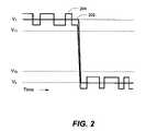
- FIG. 2is an illustration how a level of the reference spread-spectrum signal level may be set below a noise threshold of a digital operational signal in accordance with an embodiment of the present.
- V 1is the voltage for a logical “1”
- V 2is the voltage for a logical “0”.
- V T1 and V T0are the corresponding threshold voltages.
- the digital logicwill treat any voltage above V T1 as a logical “1” and any voltage below V T0 as a logical “0.”
- the difference between the V 0 and V T0(and between V 1 and V T1 ) are sometimes called the noise threshold or noise margin.
- FIG. 2illustrates the operational signal 202 and operational signal with the reference spread-spectrum signal 204 superimposed on top. As can be seen, if the voltage of the reference spread-spectrum signal is less than the noise threshold, the operational signal will be substantially unaffected.
- some minor effectsmay be acceptable during operation, and thus are included within the meaning of substantially unaffected.
- a small change in the error rate or a digital signal, or slight distortion in an analog signalmaybe acceptable.
- the direct sequence spread-spectrum signalmay be generated by translating a baseband pseudo-noise sequence by a frequency offset to produce the reference spread-spectrum signal in accordance with another embodiment of the present invention. This translation may be performed by modulating the PN sequence onto a carrier frequency at the frequency offset desired.
- a binary pseudo-noise (PN) sequenceconsisting of a series of +1 and ⁇ 1 may be used, although non-binary sequences are known in the art and are to be considered within the scope of the present invention.
- PN sequencesinclude linear feedback shift registers.
- PN sequenceshave a finite length, and may repeat every N chips.
- the PN sequenceis modulated (or multiplied) by data, and then modulated by a carrier signal at a carrier frequency to shift and center the spectrum of the PN sequence around the carrier frequency.
- this modulationmay be performed using binary or quadrature phase shift keying, or various other modulation formats known in the art which are to be considered within the scope of the invention.
- the chip rateis generally much higher than the data rate, resulting in a spread-spectrum signal bandwidth much wider than the bandwidth corresponding to the data. The higher the chip rate, and thus bandwidth, that is used, more interference resistance is generally obtained.
- the reference spread-spectrum signalBy shifting the reference spread-spectrum signal, improved performance may be obtained. For example, if the operational signal is at a low frequency, by shifting the reference spread-spectrum to a higher frequency, less interference may result. On the other hand, if the carrier frequency is set too high, dispersive propagation may occur in the signal path which may reduce accuracy. By setting the carrier frequency so that the wavelength is much larger than the expected separation of the wire from the surrounding environment, such dispersive effects may be minimized. Other factors, for example attenuation or bandwidth limitations in the signal path, may also set an upper limit on the frequency which may be used.
- the direct sequence spread-spectrum signalmay be generated by shaping the spectrum of the reference spread-spectrum in accordance with another embodiment of the present invention. This may result in improved performance. For example, by coupling less reference spread-spectrum signal energy into the signal path at frequencies where the operational signal has high energy, less interference may result.
- Correlation of a binary pseudo-noise sequencemay be performed by multiplying the two sequences together on a chip by chip basis, and then summing (or integrating) the resulting products.
- the pseudorandom signalscancel each other out, resulting in a constant output (plus any noise, operational signal, or other pseudorandom signals with different time-references).
- the sequencesmay be multiplied together and then a low pass filtering operation performed. Better accuracy using integration may be obtained than using low pass filtering.
- the number of chips for which the correlation is summed or filteredmay conveniently be set equal to the length of the PN sequence, although this is not essential.
- Correlation of a spread-spectrum signal at a carrier frequencymay be performed by mixing the spread-spectrum signal down to baseband, and then performing the above-described correlation.
- the mixingis performed using a local oscillator synchronized to the carrier frequency, this is not essential, as methods of tracking out or compensating for phase and frequency drift between two oscillators are known in the art.
- the correlation processmay also result in a reduction in interference from the operational signal.
- Any noise or operational signal that may be superimposed on the reflected spread-spectrum signalwill also be multiplied by the PN sequence during the correlation. This multiplication has the effect of spreading the spectrum of noise or operational signal superimposed on the reflected spread-spectrum signal, which is then filtered out in the following low pass filtering or integration process. Consequently, by choosing a chip rate much greater than data rate of the operational signal, interference from the operational signal may be reduced. Higher chip rates also provide benefit in improving the resolution with which the location of impedance discontinuities can be located. Similarly, longer correlation lengths (summing more product terms or lower bandwidth low pass filtering) can also filter out more noise or operational signal.
- TDRtime domain reflectometry
- TDRmay be mitigated in an embodiment of the present invention by using PN sequences. Since the resolution is a function of the chip rate, and the signal to noise ratio is a function of the PN sequence length, the resolution and sensitivity may be selected independently. The longer the time for which correlation is performed, the more energy that is coherently combined. Hence, high sensitivity may be obtained by using long correlation times (and correspondingly long PN codes).
- correlating the reference spread-spectrum signal with the reflected spread-spectrum signalit is useful to time-offset the reference spread-spectrum signal.
- the correlatingmay be performed for one particular time-offset or several different time-offsets.
- Various ways of shifting the time-offset, or time-reference, of the reference spread-spectrum signalare known, including delaying the reference spread-spectrum signal, changing the frequency of a clock generating the reference spread-spectrum signal generator, or controlling the start time of a pseudonoise generator used in generating the reference spread-spectrum signal.
- correlating at several different time-offsetsBy correlating at several different time-offsets, a plot of the response of the signal path similar to what may be observed with a time-domain reflectometer may be produced. Alternately, correlating at one particular time-offset may allow observation of dynamic changes in a particular impedance discontinuity (perhaps corresponding to an arc fault or other anomaly in the signal path).
- Correlating the reflected signal with the reference spread-spectrum signalmay be performed by shifting a time-reference of the reference spread-spectrum signal in increments of less than a chip-time in accordance with another embodiment of the present invention. This may provide improved resolution.
- the methodmay include processing the correlation result to determine the characteristic of the signal path in accordance with another embodiment of the invention. For example, based on the time-offset between the reference spread-spectrum signal and reflected spread-spectrum signal at which the correlation result has a peak, the distance to an impedance discontinuity can be found. Based on the phase and amplitude of the correlation result corresponding to the peak, various characteristics of the impedance discontinuity can also be determined. Techniques for processing are discussed in further detail below.
- the processingmay also include adjusting a system operation based on a characteristic of the signal path.
- a characteristic of the signal pathmay indicate a fault condition (e.g. a short or open circuit) that may cause damage if allowed to persist, in which case a circuit breaker or crowbar circuit may be triggered.
- a systemmay be designed to adjust operation depending on a changing impedance characteristic of the signal path, for example automatically matching a changing impedance load to the system.
- the live detection of signal path characteristic changes enabled by the methodmay have many other uses which are to be considered within the scope of the invention.
- a method 300 of testing a signal path having an anomalyis illustrated in FIG. 3 in accordance with another embodiment of the present invention.
- the methodmay include generating 302 a first reference spread-spectrum signal and a second reference spread-spectrum signal.
- the methodmay further include coupling 304 the first spread-spectrum signal into the signal path at a first location while the signal path is carrying an operational signal.
- the methodmay further include coupling 306 the second spread-spectrum signal into the signal path at a second location different than the first location while the signal path is carrying the operational signal.
- the methodmay further include receiving 308 at a third location a first reflected spread-spectrum signal from the signal path generated by the anomaly in response to the first and second spread-spectrum signals.
- the methodmay further include receiving 310 at a fourth location a second reflected spread-spectrum signal from the signal path generated by the anomaly in response to the first and second spread-spectrum signals.
- the methodmay further include correlating 312 the first reflected spread-spectrum signal with the first reference spread-spectrum signal to produce a first correlation result.
- the methodmay further include correlating 314 the second reflected spread-spectrum signal with the second reference spread-spectrum signal to produce a second correlation result.
- the methodmay further include processing 316 the first and second correlation result to determine a location of the anomaly in the signal path.
- a signal pathis illustrated in FIG. 4 in the form of a wire 410 .
- the wiremay have an anomaly 412 .
- the first reference spread-spectrum signalWhen the first reference spread-spectrum signal is injected at the first location 401 , it will travel down the wire, and a portion of the reference spread-spectrum signal will be reflected back toward location 1 . A portion of the reference spread-spectrum signal will continue to travel down the wire (unless, for example, the anomaly is an open or short circuit). This portion of the reference spread-spectrum signal may reflect off of other anomalies as will be discussed further below.
- the reflected spread-spectrum signalwill arrive back at third location 403 after a time-delay.
- the time-delaywill be the time it takes for the signal to propagate from the first location 401 to the anomaly and back to the third location 403 .
- the corresponding distancecan be found by multiplying the time-delay by the propagation velocity in the signal path. If the distance from the first location to the third location is known (or determined as discussed below) it can be subtracted out, and the distance to the anomaly found.
- the distance between the first location 401 and third location 403may be determined by measuring the delay between these locations similarly as to how delay is measured between the reference spread-spectrum signal and reflected spread-spectrum signal. In fact, distance between any two points in the signal path can be measured in this manner.
- the second reference spread-spectrum signalwhen the second reference spread-spectrum signal is injected at the second location 402 , the second reference spread-spectrum signal will travel along the signal path, and a portion reflected back towards the fourth location 404 by the anomaly 412 . Hence, the distance from the second location to the anomaly to the fourth location can be determined.
- One advantageis that improved accuracy may be obtained in determining the location of the anomaly by combining the distance measurements. For example, some uncertainty in the distance measurement is caused by uncertainty concerning the propagation velocity in the wire and noise. Distance measurements from the different locations on the wire to the anomaly may have different errors, and thus can be averaged to improve accuracy. Similarly, the actual propagation velocity in the wire may be measured by measuring the delay between known distances.
- Another advantage of the method 300is that it may be possible to sort out multiple reflections which occur due to multiple anomalies, multiple connections, or multiple reflections.
- the first reference spread-spectrum signal injected at the first location 401may be reflected from the anomaly 412 , and a portion may continue on down the wire to reflected from a wire junction 414 or even from the other end of the wire at the second location 402 . All of these reflections will propagate back toward the third location 403 and result in multiple peaks in the correlation response. Hence, it can prove difficult to sort out correlation peaks indicative of an anomaly from those indicative of a normal connection or wire end.
- Yet another advantage of the methodis apparent when there is a short or open circuit which prevents the first (or second) reference spread-spectrum signal from propagating past the anomaly. If there are multiple anomalies in the wire, only the first anomaly can be detected from one end; by testing from each end, multiple anomalies can be detected. In such a case, of course, the first (or second) reflected spread-spectrum signal will depend on only one of first or second reference spread-spectrum signals.
- the first location 401may be identical to the third location 403
- the second location 402may be identical to the fourth location 404 .
- the methodmay further include embedding the first correlation result in the first reference spread-spectrum signal and communicating the first correlation result from the first location to the fourth location.
- the methodmay further include embedding the second correlation result in the second reference spread-spectrum signal and communicating the second correlation result from the second location to the third location.
- Embedding the correlation result in the first (or second) reference spread-spectrum signalmay be accomplished by modulating the first (or second) correlation result as data onto the reference spread-spectrum signal. There are many ways this can be accomplished as will occur to one of skill in the art.
- processingmay be performed at only the third (or fourth) location permitting a simplification in the electronics.
- communication of the correlation result (or a processed version of the correlation result)may simplify communicating or displaying the location of the anomaly.
- Yet another advantageis the redundancy provided by testing from either end of the wire.
- a wire breaksmay also be detected, for example by noting the loss of the reference spread-spectrum signal from the other end of the wire.
- a system 500 for characterizing a signal path carrying an operational signalis illustrated in FIG. 5 in accordance with an embodiment of the present invention.
- the systemcan be referred to as a spread spectrum reflectometer.
- the systemmay include a signal generator 502 configured to generate a reference spread-spectrum signal.
- the reference spread-spectrum signalmay be adapted so that when applied to the signal path the operational signal is substantially unaffected.
- the systemmay further include an interface 504 coupled to the signal generator and configured to inject the reference spread-spectrum signal into the signal path 510 .
- the interfacemay be configured to extract a reflected spread-spectrum signal from the signal path generated in response to the reference spread-spectrum signal.
- the systemmay further include a corrector 506 coupled to the signal generator and coupled to the interface and configured to correlate the reflected spread-spectrum signal with the reference spread-spectrum signal to produce a correlation result.
- This correlation resultmay correspond to a characteristic of the signal path.
- Characteristics of a signal pathmay include wire length, impedance (characterized as open circuits and short circuits), the location of the open and short circuits, including intermittent opens and shorts, connection location, capacitance, inductance, resistance, and identifying and locating other anomalies on the wire, including chafes, frays, corrosion, and fluid bridging, that may be indicative of damage.
- the spread-spectrum signal generatormay be configured to produce a reference spread-spectrum signal that has a signal level below a noise threshold of the operational signal.
- the spread-spectrum signal generatormay be configured to generate a reference spread-spectrum signal has a bandwidth much greater than a bandwidth of the operational signal.
- FIG. 6is an illustration of the frequency spectrum of a simulated Mil-Std 1553 signal.
- the power spectrum of a Mil-Std 1553 signaldrops off significantly above about 5 to 10 MHz.
- the bandwidth of the spread-spectrum signalto several times this, for example 120 MHz, interference to the operational system signal can be reduced.
- the carrier (center) frequency of the spread-spectrum signalis further reduced.
- the spectrum of the reference spread-spectrum signalmay be shaped to substantially inversely mirror the spectrum of the operational signal.
- the reference spread-spectrum signal spectrummay be shaped to concentrate the power of the reference spread-spectrum signal in frequency bands where the spectrum of the operational signal is small.
- the spread-spectrum signalmay be frequency shifted into a frequency band different from that used by the operational signal to reduce potential interference or disruption of the system operation. Conversely, such shifting may be used to shift the reference spread-spectrum signal into a frequency band corresponding to a range of frequencies that the signal path permits to propagate.
- the spectrum of the reference spread-spectrum signalmay be set lower (relative to an unshaped spectrum) in the frequency range below 10 MHz, and higher in the frequency range above 30 MHz. Conversely, if the spectrum of the operational signal is mostly in a higher frequency band (for example 100 MHz), the spectrum of the reference spread-spectrum signal may be set to be primarily below this frequency (for example, using a baseband PN sequence with no frequency offset).
- the signal generator 502may be implemented by using a PN sequence generator.
- PN sequences and PN sequence generatorsare known in the art.
- Known PN sequencesinclude Walsh Codes, Barker Codes, Gold Colds, and Kasami codes.
- Known PN generatorsinclude linear recursive sequence generators, tapped feedback shift registers, and fixed memories.
- a PN generatormay be implemented in hardware using a combination of gates and delay elements, or may be implemented in software. Although a hardware implementation is presently preferred in order to provide high (many MHz) PN clock rates to yield high resolution distance measurements, some applications may be able to use lower PN clock rates and a software implementation of the PN generator.
- the performance of a PN code in the applications described hereinrelates to the auto-correlation and cross-correlation of the code.
- PN codes that have a high correlation peak at zero delay relative to the correlation for non-zero delaysare presently preferred.
- the cross-correlation of two different PN codesrelates to the performance of PN codes used for communications, and generally low cross-correlation is preferred in communications applications. When multiple reference spread-spectrum signals are coupled into the signal path, using sets of PN codes with low cross-correlation is advantageous.
- a combination of two codesmay also be used to advantage. For example, by combining a Walsh code (which has excellent cross correlation properties for some time delays) with another PN code (which has excellent auto correlation for time shifts), improved performance may be obtained.
- Maximum length codestypically have a very small off-peak correlation value and thus may be advantageous when only a single reference spread-spectrum signal is used at a time.
- Kasami codeshave very low off-peak auto-correlation and cross-correlation and thus may be advantageous when multiple reference spread-spectrum signals are used.
- the number of Kasami codesare limited, however, and if a large number of simultaneous signals are to be used, Gold codes may prove advantageous.
- the interfacemay include an isolator.
- An isolatorprovides isolation between the signal generator 502 and the signal path 510 , reducing the likelihood of damage to the signal generator from a high-voltage operational signal.
- Various types of isolatorsare known in the art, including capacitors, inductors, circulators, and directional couplers. For example, two directional couplers may be combined to allow separate injection and extraction of the reference spread-spectrum signal and reflected spread-spectrum signal, however separation of the signals is not essential.
- the interfacemay also be configured to impedance match the signal path to minimize reflections occurring at the point the reference spread-spectrum signal is injected.
- reference spread-spectrum signalneed not be coupled into the signal path at the same location from which the reflected spread-spectrum signal is extracted.
- the interface 504may also be quite simple, consisting of little more than a connector, probe, wire connection, or antenna.
- correlationmay be performed using a matched filter, finite impulse response (FIR) filter, or surface acoustic wave (SAW) device.
- Correlationmay be performed in a digital or analog format. Analog correlation may prove superior because of the higher dynamic range generally provided by analog processing.
- Correlationmay be performed sequentially (computing a correlation result at one time-offset at a time) or in parallel (computing multiple correlation results simultaneously).
- the correlationmay be performed for a single or multiple time offsets as discussed above.
- a correlatormay be implemented in digital logic using a field programmable gate array or application specific integrated circuit. Correlation may be performed using one-bit samples of the signal, or multiple-bit samples to provide higher accuracy. Correlation may also be performed by differentially amplifying a delayed and undelayed version of the signal.
- correlationmay be performed for multiple time offsets in parallel using a bank of correlators.
- improved performance in detecting short duration intermittent faultsmay be obtained.
- an intermittent faultmay last for only a single or a few cycles of the operational signal (e.g. when the operational signal is at a voltage peak). If correlation is performed too infrequently at the time-offset corresponding to the distance of the failures (anomaly), detection of the intermitted may not occur.
- performing multiple correlation in parallelmay allow increased speed and consistency in detecting of intermittent faults.
- the correlatormay be further configured to suppress interference from the operational signal.
- Spread-spectrum signalsboth baseband and modulated (frequency shifted) are detectable through correlation even though they may be buried in noise.
- the ability to pick out the signalis due to processing gain, which for Direct Sequence Spread-spectrum (DSSS) can be expressed as
- W ssthe bandwidth of the spread-spectrum signal
- T sis the duration of one entire PN sequence (considering the entire sequence equal to one bit of data in communication-system terms)
- T cis the duration of a PN Code chip
- R cis the chip rate in chips per second
- R sis the symbol rate of the number of full sequences per second.
- FIG. 7is an illustration of the signals obtained in baseband sequence time domain reflectometry (STDR) in accordance with an embodiment of the present invention.
- STDRbaseband sequence time domain reflectometry
- the PN sequenceis the injected reference spread-spectrum signal.
- the STDR plotshows the reflected spread-spectrum signal superimposed on the reference spread-spectrum signal.
- the correlation resultis shown in the bottom plot.
- the ‘+’ marksshow the data that may be collected if the system only computed the correlation result at full chip-time time-offsets.
- improved performance in locating impedance discontinuitiesmay be obtained by computing the correlation result at time-offsets of less than chip-time.
- an embodiment of the present inventionincludes wherein the correlator is further configured to generate the correlation result for a time-offset of less than a chip-time.
- FIG. 8is a similar illustration of the signal obtained in a spread-spectrum time domain reflectometer (SSTDR) in accordance with an embodiment of the present invention. As can be seen, similar results are obtained to the STDR, although the signals have been shifted in frequency.
- SSTDRspread-spectrum time domain reflectometer
- another embodiment of the present inventionincludes wherein the correlator is further configured to interpolate a plurality of correlation results to provide an improved accuracy correlation result.
- Various methods of interpolationare known in the art. One technique for interpolating is to find the vertical midpoints of both sides of the correlation peak, and from that, estimate the location of the center of the correlation peaks. Another method is to perform curve fitting by superimposing a copy of a basis function correlation peak over the correlation peak observed, and adjusting the basis function in amplitude and horizontal position until it matches peak from the reflected signal in the least means squares sense.
- Various methods to adjust the basis functionare known, including linear search, gradient, conjugate gradient, Newton, and regularized Newton algorithms.
- Another embodiment of the present inventionfurther includes a processor or control element coupled to the correlator and configured to determine the characteristic of the signal path from the correlation result.
- the processormay be implemented using hardware, software, or a combination. Various characteristics, including impedance may be determined
- a peak of the correlation resultmay occur at a time offset corresponding to the distance to an impedance discontinuity.
- the amplitude of the reflected signalwill be proportional to the reflection coefficient
- ⁇ LZ L - z 0 Z L + z 0
- Z Limpedance at the discontinuity
- z othe impedance of the wire.
- the reflection coefficientcan take an any value between ⁇ 1 and 1.
- the peak correlation resultprovides a measure of the reflection coefficient, which can be solved to find the impedance value at the discontinuity.
- FIG. 10illustrates the correlation result for an example of a capacitance impedance discontinuity located at the end of the wire.
- FIG. 11illustrates the correlation result for the example of an inductive impedance discontinuity located at the end of the wire.
- Another embodiment of the present inventionmay further include a memory unit coupled to the processor and configured to store a history of the characteristic of the signal path.
- a historyBy storing a history, intermittent faults may be located. For example, a baseline correlation result may be obtained when the signal path has no anomalies, and later correlation results compared to the baseline to detect partial faults. Alternately, a window of past correlation results may be stored, and new correlation results compared to previous measurements, comparing to the first, the last, multiple, or an average of multiple measurements within this window.
- a “peak” in the correlation resultmay appear that represents the location of the arc fault.
- Several readingsmay be stored, and compared sequentially. The maximum differences between the average or median of the readings may be obtained. The arc fault may therefore show up as a peak in the maximum difference data at the location proportional to the location of the arc fault.
- the fault locationmay be assumed to be centered about the location where the later correlation result deviates from the baseline.
- Baseliningcan also be used to provide for calibration, long term trend measurement, and removal of initial correlation peaks from impedance discontinuities at the location the reference spread-spectrum signal is injected and the location the reflected spread-spectrum signal is extracted.
- the history storagemay also be used to assist in locating intermittent faults on non-controlled impedance cables.
- the correlation resultmay be stored when a fault condition occurs, and the a technician may later use a probe to trace the wire, moving along the length of the wire until the correlation result obtained with the probe matches that stored for the failure condition.
- Another embodiment of the present inventionmay include a circuit breaker coupled to the processor.
- the processormay be configured to trip the circuit breaker when a change in the characteristic of the signal path indicates a fault condition. For example, a sudden change in impedance, or the sudden appearance of additional peaks in the correlation result may indicate a fault condition caused by a short circuit.
- more than one signal generator, interface, and correlatormay be included.
- the additional signal generatorsmay be configured to generate a reference spread-spectrum signal adapted so that the other reference spread-spectrum signals are substantially unaffected. This may permit testing of multiple signal paths simultaneously, while minimizing interference due to crosstalk.
- FIG. 9A system 900 for detecting an anomaly in a signal path carrying an operational signal is illustrated in FIG. 9 in accordance with another embodiment of the present invention.
- the systemmay include a plurality 902 of signal generators 502 configured to generate a plurality of reference spread-spectrum signals wherein the plurality of reference spread-spectrum signals are adapted so that when applied to the signal path the operational signal is substantially unaffected.
- the systemmay further include at least one injector 904 coupled to the plurality of signal generators and configured to inject the plurality of spread-spectrum signals into the signal path 510 .
- a single injector configured to inject multiple reference spread-spectrum signalsmay be included, or multiple injectors configured to each inject a single reference spread-spectrum signal may be included.
- the injectorsmay inject the reference spread-spectrum signals at the same or different places.
- the systemmay further include at least one extractor 906 coupled to the signal path and configured to extract a plurality of reflected spread-spectrum signals from the signal path generated by the anomaly in response to the plurality of reference spread-spectrum signals.
- the extractor(s)may be configured to extract the reference spread-spectrum signals from the same or different location than the injector(s).
- the systemmay further include at least one correlator 908 coupled to the plurality of signal generators and coupled to the at least one extractor and configured to correlate the plurality of reflected spread-spectrum signals with the plurality of reference spread-spectrum signal to produce a plurality of correlation results.
- a single correlatormay be used to perform correlations for the different reference spread-spectrum signals at different times, or multiple correlators may be used to perform multiple correlations (for different reference spread-spectrum signals or different time-offsets) simultaneously.
- the systemmay further include a processor 910 coupled to the at least one correlator and coupled to the at least one extractor and configured to determine a location of the anomaly from the plurality of correlation results.
- FIG. 12illustrates a detailed implementation of a system, shown generally at 600 , for characterizing a signal path in accordance with an embodiment of the present invention.
- the signal path being tested 602may be modeled as a continuous-time invariant system with impulse response ⁇ (t ⁇ ) where ⁇ is the time required for a signal to propagate from a transmitter (source) to a receiver (destination) over the signal path and ⁇ is the reflection coefficient.
- a spread-spectrum signalis used to probe the signal path.
- the spread-spectrum signalis generated by a code.
- the codemay be generated by a circularly shifted code buffer 604 .
- the code bitsare used to modulate a spreading pulse p(t) 606 . Although amplitude modulation is presently preferred, phase or other forms of modulation may also be used.
- the signal at point A and Bmay be represented as:
- A((n)) Nis meant the code sequence a(n) is indexed modulo N (also referred to a circularly shifted). This mathematical notation corresponds to the circular shifting of the code buffer.
- the code sequenceis self-orthogonal in the following sense:
- the parameter T cis the chip time or chip period. Dividing the time delay T by the chip time leads to:
- the optimum (maximum likelihood) estimator of the time delay(assume white Gaussian noise may also be added by the signal path or sensor) is a filter matched to the signal s(t).
- the position in time of the peak in the matched filter outputcorresponds to the maximum likelihood estimate of the time delay.
- a correlation based circuit realization of the maximum likelihood filteris suitable for high frequency hardware implementation.
- the cross correlation circuit 606is also shown in FIG. 12 .
- the time delay estimateis taken to be the position of the peak in the cross correlation function between the received signal s(t ⁇ ) and a synthetically generated replica s(t ⁇ T c ) at point C.
- FIG. 12Although only a single cross correlator is shown in FIG. 12 which sequentially computes the N values of the cross correlation function, multiple cross correlators may be included to allow parallel computation of the N values of the cross correlation function.
- the signal at point C in FIG. 10is thus given by:
- This signalis generated by a circular delay of the code bits relative to the code sequence used to generate the probe signal s(t).
- the output of the correlator at point Dis thus given by:
- g ⁇ ( ⁇ )⁇ 0 NT c ⁇ p ⁇ ( t ) ⁇ p ⁇ ( t - ⁇ ) ⁇ ⁇ d t
- r( ⁇ )is equal to zero except when ⁇ is equal to k or k+1.
- kis that the integer number of chip periods in the unknown delay ⁇ .
- the function g(t)which is known, can be used to extrapolate between the non zero samples r(k) and r(k+1) to obtain the fractional delay ⁇ and the reflection coefficient ⁇ .
- spread-spectrum signalsenable high resolution estimation of ⁇ and ⁇ .
- correlationmay be performed at non-integer chip period, e.g. one-half, one-quarter, or smaller fractions of a chip period.
- the wiremay be modeled by:
- ⁇ i1 L ⁇ ⁇ i ⁇ ⁇ ⁇ ( t - ⁇ i )
- each of the reflectionsmay be resolved individually. If some of the reflections are closely spaced, then Fourier based techniques as known to those skilled in the art may also be applied to extract the time delays.
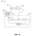
- FIG. 13illustrates a block diagram of an application of an embodiment of the present invention.
- the systemmay include a signal generator 502 , an interface 504 and a processor 508 .
- the signal generator 502may be configured to generate either a STDR or SSTDR signal, or both simultaneously.
- the signal generatormay include an oscillator 232 .
- the signal generatormay also include a PN generator 234 .
- the oscillatormay be used to provide the clock for the PN generator as shown here.
- a shaper 238may be used to convert the sinewave output of the oscillator to a suitable square wave for clocking the PN generator.
- the oscillatormay also be used to provide the carrier frequency for applying frequency offset to the PN sequence in a mixer 240 .
- a switch 242may be used to select either the STDR or SSTDR mode of operation.
- the reference spread-spectrum signal(at point RF 1 ) may be applied to a signal path or cable 510 through the interface 504 .
- the interfacemay include a resister R.
- the resistermay be used to help match the impedance of the cable.
- the interfacemay include a capacitor C.
- the capacitormay be used to help isolate the signal generator 502 from the cable, for example to prevent high DC or AC voltages on the line from damaging the signal generator or correlator 508 .
- Various values of R and Cmay be selected to control the relative response of the coupler 504 to the reference spread-spectrum signal, reflected spread-spectrum signal, and operational signal 250 .
- STDRit is preferable to use the switch SW to bypass the capacitor because STDR contains mostly low frequency spectral content.
- the correlator 506may include a variable phase delay 244 , coupled to a shaper 238 , PN generator 234 , and mixer 240 configured similarly to the signal generator to produce a phase delayed version of the reference spread-spectrum signal at point RF 2 .
- the variable phase delaymay be used to time-offset the delayed version of the reference spread-spectrum signal by time-offsets of up to a chip-time.
- the time-offsetmay be adjusted in virtually any step desired. It is preferable that the time-offset be incremented in steps of less than one-quarter chip time.
- Time-offset in the delayed reference spread-spectrum signalmay also be introduced by varying the start time of the delayed reference spread-spectrum signal relative to the reference spread-spectrum signal by one or more whole chip-time using the PN generator control 2322 .
- the correlatormay also include a mixer 240 ′.
- the delayed reference spread-spectrum signalmay be mixed with the reflected spread-spectrum signal using the mixer.
- the correlatormay also include an integrator 256 and integrator control 258 .
- the output of the integratormay provide a correlation result to the processor 508 .
- the integrator controlmay reset the integrator at the beginning of a correlation interval (for example a particular time-offset) and trigger a sampling of the correlation result.
- the processor 508may include and analog to digital converter (ADC) 260 to convert the correlation result into a digital format for further analysis.
- the processormay further include an ADC control 262 to synchronize the ADC conversion time with the operation of correlator 506 and signal generator 502 .
- the processormay further include a computer interface (PC interface) 264 .
- the computer interfacemay be used to allow computer control operation of the system, and to allow computer analysis of the correlation results.
- Some of the devices where embodiments of the present invention can be usedinclude a stand-alone dedicated device, an integrated assembly within system component, an add-on into an existing system component, a multi-function measurement device, a laptop computer, a desktop personal computer, in the insulation of the wire, in a connector between wires, on a circuit board that can be installed in after-market devices, in an arc-fault circuit breaker, in a battery, in an add-on assembly for insertion between a probe and multi-function meter, and in probes that can be used with after-market devices.
- the stand-alone and multi-function measurement devicesare of particular importance.
- the system 500may be installed inside the FLUKETM device so that measuring short circuits and open circuits is simply another option on a dial.
- the handheld devicemay have the capability of displaying the distance, for example, in meters to the anomaly. In those situations where the system is an aftermarket addition, the handheld device may display the voltage, and then the user may translate the voltage to a distance reading.
- Such a handheld devicemight be provided with a connector that allows easy connection of the device to a connectorized wiring harness.
- a multiplexer or switchmay be used to switch to each wire in the harness individually. This greatly increases the convenience of such a test instrument and the reliability of test results, since the user need not move a probe to each wire or connector pin.
- the handheld devicehas been described as a FLUKETM multimeter device. However, there are other handheld computational and measurement devices that can also be used. For example, consider the JuniperTM Ruggedized Handheld PC.
- the system 500may also be constructed to fit into a slot in a measurement device, wherein the slot is provided so that functionality can be added to existing devices.
- the ability to retro-fit existing devicesis an important application of the presently disclosed inventive concepts.
- an embodiment of the present inventionmay be integrated directly into new products, function as a stand-alone device, or be manufactured as an add-on for use in combination with other devices.
- the arc-fault circuit breakeris an application of particular importance.
- a circuit breakeris a commonly available junction point in a circuit.
- Arc faultscan be very small, and even invisible to the unaided eye. It is very difficult to be able to repair the wire if the fault cannot be seen.
- the system 500may enable the presence and location of an arc fault to be determined to a high degree of accuracy.
- the systemmay be integrated into existing or new circuit breakers, or otherwise placed within a circuit breaker panel. Power required to operate the present invention may conveniently be obtained directly from the wire signal path tested.
- the system 500may also be integrated into the connectors of a wiring harness.
- Existing connectorsmay be replaced or a separate “connector-saver” that has male pins on one side and female sockets on the other so that the existing connectors may be plugged into either side of this connector-saver.
- the new connectors and connector-savermay each contain the presently disclosed inventive techniques, permitting in-system testing for anomalies within the wiring harness.
- the connectormay connect to power within the bundle being tested.
- the connectormay include a battery (possibly rechargeable).
- the connectormay scavenge power from the surroundings using vibration, thermal changes, or other well-known power scavenging methods.
- each connectormay provide a communication interface to get anomaly data back to a central location for examination by a maintenance technician, operator, pilot, remote decision-making interface, or the like.
- each connectormay include a communication link that could be either hard-wired or wireless, e.g., RF, IR, etc.
- the connectormay be examined visually or individually. The examination may be facilitated with a set of LED outputs, or a hard-wired or wireless connection between a handheld PDA, for example and not by way of limitation.
- the connectormay include a multiplexer or set of switches to test each of the wires separately.
- the systemmay be built into a single chip, embedded into the connector and may test the set of several wires simultaneously.
- One of the more immediate applications of the present inventive techniqueis the ability to use a handheld device for testing wires for short and open circuits. For example, airplane wiring can be tested using embodiments of the present invention, even when there is no return path. Thus, a single wire can be tested.
Landscapes
- Engineering & Computer Science (AREA)
- Computer Networks & Wireless Communication (AREA)
- Signal Processing (AREA)
- Power Engineering (AREA)
- Physics & Mathematics (AREA)
- General Physics & Mathematics (AREA)
- Radar Systems Or Details Thereof (AREA)
Abstract
Description
where Wssis the bandwidth of the spread-spectrum signal, Tsis the duration of one entire PN sequence (considering the entire sequence equal to one bit of data in communication-system terms), Tcis the duration of a PN Code chip, Rcis the chip rate in chips per second, and Rsis the symbol rate of the number of full sequences per second. By setting this processing gain to a required level, interfering operational signals (for example, a 400 Hz 115V AC or digital data on the wires) can be suppressed.
where ZLis impedance at the discontinuity and zois the impedance of the wire. The reflection coefficient can take an any value between −1 and 1. Hence, the peak correlation result provides a measure of the reflection coefficient, which can be solved to find the impedance value at the discontinuity.
where by A((n))Nis meant the code sequence a(n) is indexed modulo N (also referred to a circularly shifted). This mathematical notation corresponds to the circular shifting of the code buffer.
where δ is the Kronecker delta.
where k is the whole number of chip times in the signal path delay and α is the fractional part of a chip time. If α=0 then τ is in integer multiple of chip times. With this decomposition of the delay, the goal is to estimate the pair (k, α). Using the previous two expressions and a change of variables, s(t−τ) can be written as:
where the final step in the derivation above is enabled by the auto correlation property (high peak correlation at zero time-offset and low autocorrelation at other time-offsets) of the spreading code. The function g(t) above is equal to the autocorrelation function of the pulse p(t), given by:
where γiand τiare the reflection coefficients and time delays i=1, . . . L. The time delays may be written in terms of whole and fractional parts:
τi=(ki+αi)Tc
Claims (38)
Priority Applications (1)
| Application Number | Priority Date | Filing Date | Title |
|---|---|---|---|
| US11/198,900US7250772B2 (en) | 2002-11-19 | 2005-08-04 | Method and apparatus for characterizing a signal path carrying an operational signal |
Applications Claiming Priority (9)
| Application Number | Priority Date | Filing Date | Title |
|---|---|---|---|
| US42773702P | 2002-11-19 | 2002-11-19 | |
| US44476103P | 2003-02-04 | 2003-02-04 | |
| US45578803P | 2003-03-18 | 2003-03-18 | |
| US45948203P | 2003-03-31 | 2003-03-31 | |
| US47739103P | 2003-06-09 | 2003-06-09 | |
| PCT/US2003/037233WO2004046652A2 (en) | 2002-11-19 | 2003-11-19 | Device and method for detecting anomolies in a wire and related sensing methods |
| PCT/US2004/003343WO2004070398A2 (en) | 2003-02-04 | 2004-02-04 | Method and apparatus for characterizing a signal path carrying an operational signal |
| US11/133,145US7495450B2 (en) | 2002-11-19 | 2005-05-18 | Device and method for detecting anomolies in a wire and related sensing methods |
| US11/198,900US7250772B2 (en) | 2002-11-19 | 2005-08-04 | Method and apparatus for characterizing a signal path carrying an operational signal |
Related Parent Applications (3)
| Application Number | Title | Priority Date | Filing Date |
|---|---|---|---|
| PCT/US2003/037233Continuation-In-PartWO2004046652A2 (en) | 2002-11-19 | 2003-11-19 | Device and method for detecting anomolies in a wire and related sensing methods |
| PCT/US2004/003343Continuation-In-PartWO2004070398A2 (en) | 2002-11-19 | 2004-02-04 | Method and apparatus for characterizing a signal path carrying an operational signal |
| US11/133,145Continuation-In-PartUS7495450B2 (en) | 2002-11-19 | 2005-05-18 | Device and method for detecting anomolies in a wire and related sensing methods |
Related Child Applications (1)
| Application Number | Title | Priority Date | Filing Date |
|---|---|---|---|
| PCT/US2004/003343Continuation-In-PartWO2004070398A2 (en) | 2002-11-19 | 2004-02-04 | Method and apparatus for characterizing a signal path carrying an operational signal |
Publications (2)
| Publication Number | Publication Date |
|---|---|
| US20060012376A1 US20060012376A1 (en) | 2006-01-19 |
| US7250772B2true US7250772B2 (en) | 2007-07-31 |
Family
ID=35717458
Family Applications (1)
| Application Number | Title | Priority Date | Filing Date |
|---|---|---|---|
| US11/198,900Expired - LifetimeUS7250772B2 (en) | 2002-11-19 | 2005-08-04 | Method and apparatus for characterizing a signal path carrying an operational signal |
Country Status (1)
| Country | Link |
|---|---|
| US (1) | US7250772B2 (en) |
Cited By (157)
| Publication number | Priority date | Publication date | Assignee | Title |
|---|---|---|---|---|
| US20070194796A1 (en)* | 2006-01-31 | 2007-08-23 | Reid Harrison | Reflectometry test system using a sliding pseudo-noise reference |
| US20090132190A1 (en)* | 2004-09-09 | 2009-05-21 | Formfactor, Inc. | Method and apparatus for remotely buffering test channels |
| US20090228223A1 (en)* | 2008-03-04 | 2009-09-10 | Zhenning Liu | Power line communication based aircraft power distribution system with real time wiring integrity monitoring capability |
| US20100063754A1 (en)* | 2008-09-11 | 2010-03-11 | Thomas Terrance L | Wire fault illumination and display |
| US20100268507A1 (en)* | 2009-04-20 | 2010-10-21 | Universal Synaptics Corporation | Apparatus for testing multiple conductor wiring and terminations for electronic systems |
| US20100315065A1 (en)* | 2009-06-16 | 2010-12-16 | Durston Thomas W | Wideband high impendance bridging module |
| US20110036155A1 (en)* | 2004-12-29 | 2011-02-17 | Rain Bird Corporation | Soil Moisture Sensor and Controller |
| US20110153235A1 (en)* | 2009-12-23 | 2011-06-23 | The Boeing Company | Wire System Assessment |
| US20110181295A1 (en)* | 2010-01-22 | 2011-07-28 | Livewire Test Labs, Inc. | Fault detection using combined reflectometry and electronic parameter measurement |
| US20120212504A1 (en)* | 2011-02-22 | 2012-08-23 | International Business Machines Corporation | Method and system for extracting compact models for circuit simulation |
| US20140103937A1 (en)* | 2012-10-16 | 2014-04-17 | The University Of Utah | State of Health Estimation of Power Converters |
| US20150236643A1 (en)* | 2014-02-19 | 2015-08-20 | The University Of Utah | Systems and methods for fault detection |
| US9238580B2 (en) | 2013-03-11 | 2016-01-19 | Analog Devices Global | Spread-spectrum MEMS self-test system and method |
| US20160103944A1 (en)* | 2014-10-10 | 2016-04-14 | Signal Integrity Software, Inc. | System and method for signal integrity waveform decomposition analysis |
| US9476932B2 (en) | 2013-03-15 | 2016-10-25 | University Of Utah Foundation | Systems and methods for implementing S/SSTDR measurements |
| US9640850B2 (en) | 2015-06-25 | 2017-05-02 | At&T Intellectual Property I, L.P. | Methods and apparatus for inducing a non-fundamental wave mode on a transmission medium |
| US9667317B2 (en) | 2015-06-15 | 2017-05-30 | At&T Intellectual Property I, L.P. | Method and apparatus for providing security using network traffic adjustments |
| US9674711B2 (en) | 2013-11-06 | 2017-06-06 | At&T Intellectual Property I, L.P. | Surface-wave communications and methods thereof |
| US9685992B2 (en) | 2014-10-03 | 2017-06-20 | At&T Intellectual Property I, L.P. | Circuit panel network and methods thereof |
| US9705610B2 (en) | 2014-10-21 | 2017-07-11 | At&T Intellectual Property I, L.P. | Transmission device with impairment compensation and methods for use therewith |
| US9705561B2 (en) | 2015-04-24 | 2017-07-11 | At&T Intellectual Property I, L.P. | Directional coupling device and methods for use therewith |
| US9722318B2 (en) | 2015-07-14 | 2017-08-01 | At&T Intellectual Property I, L.P. | Method and apparatus for coupling an antenna to a device |
| US9729197B2 (en) | 2015-10-01 | 2017-08-08 | At&T Intellectual Property I, L.P. | Method and apparatus for communicating network management traffic over a network |
| US9735833B2 (en) | 2015-07-31 | 2017-08-15 | At&T Intellectual Property I, L.P. | Method and apparatus for communications management in a neighborhood network |
| US9742521B2 (en) | 2014-11-20 | 2017-08-22 | At&T Intellectual Property I, L.P. | Transmission device with mode division multiplexing and methods for use therewith |
| US9742462B2 (en) | 2014-12-04 | 2017-08-22 | At&T Intellectual Property I, L.P. | Transmission medium and communication interfaces and methods for use therewith |
| US9749053B2 (en) | 2015-07-23 | 2017-08-29 | At&T Intellectual Property I, L.P. | Node device, repeater and methods for use therewith |
| US9749013B2 (en) | 2015-03-17 | 2017-08-29 | At&T Intellectual Property I, L.P. | Method and apparatus for reducing attenuation of electromagnetic waves guided by a transmission medium |
| US9748626B2 (en) | 2015-05-14 | 2017-08-29 | At&T Intellectual Property I, L.P. | Plurality of cables having different cross-sectional shapes which are bundled together to form a transmission medium |
| US9762289B2 (en) | 2014-10-14 | 2017-09-12 | At&T Intellectual Property I, L.P. | Method and apparatus for transmitting or receiving signals in a transportation system |
| US9768833B2 (en) | 2014-09-15 | 2017-09-19 | At&T Intellectual Property I, L.P. | Method and apparatus for sensing a condition in a transmission medium of electromagnetic waves |
| US9769020B2 (en) | 2014-10-21 | 2017-09-19 | At&T Intellectual Property I, L.P. | Method and apparatus for responding to events affecting communications in a communication network |
| US9769128B2 (en) | 2015-09-28 | 2017-09-19 | At&T Intellectual Property I, L.P. | Method and apparatus for encryption of communications over a network |
| US9780834B2 (en) | 2014-10-21 | 2017-10-03 | At&T Intellectual Property I, L.P. | Method and apparatus for transmitting electromagnetic waves |
| US9787412B2 (en) | 2015-06-25 | 2017-10-10 | At&T Intellectual Property I, L.P. | Methods and apparatus for inducing a fundamental wave mode on a transmission medium |
| US9788326B2 (en) | 2012-12-05 | 2017-10-10 | At&T Intellectual Property I, L.P. | Backhaul link for distributed antenna system |
| US9793954B2 (en) | 2015-04-28 | 2017-10-17 | At&T Intellectual Property I, L.P. | Magnetic coupling device and methods for use therewith |
| US9793951B2 (en) | 2015-07-15 | 2017-10-17 | At&T Intellectual Property I, L.P. | Method and apparatus for launching a wave mode that mitigates interference |
| US9793955B2 (en) | 2015-04-24 | 2017-10-17 | At&T Intellectual Property I, Lp | Passive electrical coupling device and methods for use therewith |
| US9800327B2 (en) | 2014-11-20 | 2017-10-24 | At&T Intellectual Property I, L.P. | Apparatus for controlling operations of a communication device and methods thereof |
| US9820146B2 (en) | 2015-06-12 | 2017-11-14 | At&T Intellectual Property I, L.P. | Method and apparatus for authentication and identity management of communicating devices |
| US9832089B2 (en) | 2015-01-07 | 2017-11-28 | Arcom Digital, Llc | Detecting leakage of OFDM signals from an HFC network |
| US9838896B1 (en) | 2016-12-09 | 2017-12-05 | At&T Intellectual Property I, L.P. | Method and apparatus for assessing network coverage |
| US9838078B2 (en) | 2015-07-31 | 2017-12-05 | At&T Intellectual Property I, L.P. | Method and apparatus for exchanging communication signals |
| US9847850B2 (en) | 2014-10-14 | 2017-12-19 | At&T Intellectual Property I, L.P. | Method and apparatus for adjusting a mode of communication in a communication network |
| US9847566B2 (en) | 2015-07-14 | 2017-12-19 | At&T Intellectual Property I, L.P. | Method and apparatus for adjusting a field of a signal to mitigate interference |
| US9853342B2 (en) | 2015-07-14 | 2017-12-26 | At&T Intellectual Property I, L.P. | Dielectric transmission medium connector and methods for use therewith |
| US9860075B1 (en) | 2016-08-26 | 2018-01-02 | At&T Intellectual Property I, L.P. | Method and communication node for broadband distribution |
| US9866309B2 (en) | 2015-06-03 | 2018-01-09 | At&T Intellectual Property I, Lp | Host node device and methods for use therewith |
| US9866276B2 (en) | 2014-10-10 | 2018-01-09 | At&T Intellectual Property I, L.P. | Method and apparatus for arranging communication sessions in a communication system |
| US9865911B2 (en) | 2015-06-25 | 2018-01-09 | At&T Intellectual Property I, L.P. | Waveguide system for slot radiating first electromagnetic waves that are combined into a non-fundamental wave mode second electromagnetic wave on a transmission medium |
| US9871282B2 (en) | 2015-05-14 | 2018-01-16 | At&T Intellectual Property I, L.P. | At least one transmission medium having a dielectric surface that is covered at least in part by a second dielectric |
| US9871283B2 (en) | 2015-07-23 | 2018-01-16 | At&T Intellectual Property I, Lp | Transmission medium having a dielectric core comprised of plural members connected by a ball and socket configuration |
| US9871558B2 (en) | 2014-10-21 | 2018-01-16 | At&T Intellectual Property I, L.P. | Guided-wave transmission device and methods for use therewith |
| US9876571B2 (en) | 2015-02-20 | 2018-01-23 | At&T Intellectual Property I, Lp | Guided-wave transmission device with non-fundamental mode propagation and methods for use therewith |
| US9876605B1 (en) | 2016-10-21 | 2018-01-23 | At&T Intellectual Property I, L.P. | Launcher and coupling system to support desired guided wave mode |
| US9876264B2 (en) | 2015-10-02 | 2018-01-23 | At&T Intellectual Property I, Lp | Communication system, guided wave switch and methods for use therewith |
| US9882663B2 (en) | 2016-03-17 | 2018-01-30 | Arcom Digital, Llc | Doppler location of signal leaks in an HFC network |
| US9882668B2 (en) | 2014-09-18 | 2018-01-30 | Arcom Digital, Llc | Detecting leakage of OFDM signals from an HFC network |
| US9882257B2 (en) | 2015-07-14 | 2018-01-30 | At&T Intellectual Property I, L.P. | Method and apparatus for launching a wave mode that mitigates interference |
| US9887447B2 (en) | 2015-05-14 | 2018-02-06 | At&T Intellectual Property I, L.P. | Transmission medium having multiple cores and methods for use therewith |
| US9893795B1 (en) | 2016-12-07 | 2018-02-13 | At&T Intellectual Property I, Lp | Method and repeater for broadband distribution |
| US9904535B2 (en) | 2015-09-14 | 2018-02-27 | At&T Intellectual Property I, L.P. | Method and apparatus for distributing software |
| US9906269B2 (en) | 2014-09-17 | 2018-02-27 | At&T Intellectual Property I, L.P. | Monitoring and mitigating conditions in a communication network |
| US9911020B1 (en) | 2016-12-08 | 2018-03-06 | At&T Intellectual Property I, L.P. | Method and apparatus for tracking via a radio frequency identification device |
| US9913139B2 (en) | 2015-06-09 | 2018-03-06 | At&T Intellectual Property I, L.P. | Signal fingerprinting for authentication of communicating devices |
| US9912381B2 (en) | 2015-06-03 | 2018-03-06 | At&T Intellectual Property I, Lp | Network termination and methods for use therewith |
| US9912033B2 (en) | 2014-10-21 | 2018-03-06 | At&T Intellectual Property I, Lp | Guided wave coupler, coupling module and methods for use therewith |
| US9912027B2 (en) | 2015-07-23 | 2018-03-06 | At&T Intellectual Property I, L.P. | Method and apparatus for exchanging communication signals |
| US9912419B1 (en) | 2016-08-24 | 2018-03-06 | At&T Intellectual Property I, L.P. | Method and apparatus for managing a fault in a distributed antenna system |
| US9917341B2 (en) | 2015-05-27 | 2018-03-13 | At&T Intellectual Property I, L.P. | Apparatus and method for launching electromagnetic waves and for modifying radial dimensions of the propagating electromagnetic waves |
| US9927517B1 (en) | 2016-12-06 | 2018-03-27 | At&T Intellectual Property I, L.P. | Apparatus and methods for sensing rainfall |
| US9929755B2 (en) | 2015-07-14 | 2018-03-27 | At&T Intellectual Property I, L.P. | Method and apparatus for coupling an antenna to a device |
| US9930668B2 (en) | 2013-05-31 | 2018-03-27 | At&T Intellectual Property I, L.P. | Remote distributed antenna system |
| US9948333B2 (en) | 2015-07-23 | 2018-04-17 | At&T Intellectual Property I, L.P. | Method and apparatus for wireless communications to mitigate interference |
| US9948354B2 (en) | 2015-04-28 | 2018-04-17 | At&T Intellectual Property I, L.P. | Magnetic coupling device with reflective plate and methods for use therewith |
| US9948355B2 (en) | 2014-10-21 | 2018-04-17 | At&T Intellectual Property I, L.P. | Apparatus for providing communication services and methods thereof |
| US9954287B2 (en) | 2014-11-20 | 2018-04-24 | At&T Intellectual Property I, L.P. | Apparatus for converting wireless signals and electromagnetic waves and methods thereof |
| US9954286B2 (en) | 2014-10-21 | 2018-04-24 | At&T Intellectual Property I, L.P. | Guided-wave transmission device with non-fundamental mode propagation and methods for use therewith |
| US9960842B2 (en) | 2015-10-12 | 2018-05-01 | Arcom Digital, Llc | Network traffic-compatible time domain reflectometer |
| US9967173B2 (en) | 2015-07-31 | 2018-05-08 | At&T Intellectual Property I, L.P. | Method and apparatus for authentication and identity management of communicating devices |
| US9973940B1 (en) | 2017-02-27 | 2018-05-15 | At&T Intellectual Property I, L.P. | Apparatus and methods for dynamic impedance matching of a guided wave launcher |
| US9973416B2 (en) | 2014-10-02 | 2018-05-15 | At&T Intellectual Property I, L.P. | Method and apparatus that provides fault tolerance in a communication network |
| US9991580B2 (en) | 2016-10-21 | 2018-06-05 | At&T Intellectual Property I, L.P. | Launcher and coupling system for guided wave mode cancellation |
| US9997819B2 (en) | 2015-06-09 | 2018-06-12 | At&T Intellectual Property I, L.P. | Transmission medium and method for facilitating propagation of electromagnetic waves via a core |
| US9998870B1 (en) | 2016-12-08 | 2018-06-12 | At&T Intellectual Property I, L.P. | Method and apparatus for proximity sensing |
| US9999038B2 (en) | 2013-05-31 | 2018-06-12 | At&T Intellectual Property I, L.P. | Remote distributed antenna system |
| US10009067B2 (en) | 2014-12-04 | 2018-06-26 | At&T Intellectual Property I, L.P. | Method and apparatus for configuring a communication interface |
| US10020844B2 (en) | 2016-12-06 | 2018-07-10 | T&T Intellectual Property I, L.P. | Method and apparatus for broadcast communication via guided waves |
| US10027398B2 (en) | 2015-06-11 | 2018-07-17 | At&T Intellectual Property I, Lp | Repeater and methods for use therewith |
| US10027397B2 (en) | 2016-12-07 | 2018-07-17 | At&T Intellectual Property I, L.P. | Distributed antenna system and methods for use therewith |
| US10033108B2 (en) | 2015-07-14 | 2018-07-24 | At&T Intellectual Property I, L.P. | Apparatus and methods for generating an electromagnetic wave having a wave mode that mitigates interference |
| US10044409B2 (en) | 2015-07-14 | 2018-08-07 | At&T Intellectual Property I, L.P. | Transmission medium and methods for use therewith |
| US10069535B2 (en) | 2016-12-08 | 2018-09-04 | At&T Intellectual Property I, L.P. | Apparatus and methods for launching electromagnetic waves having a certain electric field structure |
| US10079661B2 (en) | 2015-09-16 | 2018-09-18 | At&T Intellectual Property I, L.P. | Method and apparatus for use with a radio distributed antenna system having a clock reference |
| US10090594B2 (en) | 2016-11-23 | 2018-10-02 | At&T Intellectual Property I, L.P. | Antenna system having structural configurations for assembly |
| US10090606B2 (en) | 2015-07-15 | 2018-10-02 | At&T Intellectual Property I, L.P. | Antenna system with dielectric array and methods for use therewith |
| US10103422B2 (en) | 2016-12-08 | 2018-10-16 | At&T Intellectual Property I, L.P. | Method and apparatus for mounting network devices |
| US10135146B2 (en) | 2016-10-18 | 2018-11-20 | At&T Intellectual Property I, L.P. | Apparatus and methods for launching guided waves via circuits |
| US10135145B2 (en) | 2016-12-06 | 2018-11-20 | At&T Intellectual Property I, L.P. | Apparatus and methods for generating an electromagnetic wave along a transmission medium |
| US10135147B2 (en) | 2016-10-18 | 2018-11-20 | At&T Intellectual Property I, L.P. | Apparatus and methods for launching guided waves via an antenna |
| US10136434B2 (en) | 2015-09-16 | 2018-11-20 | At&T Intellectual Property I, L.P. | Method and apparatus for use with a radio distributed antenna system having an ultra-wideband control channel |
| US10139820B2 (en) | 2016-12-07 | 2018-11-27 | At&T Intellectual Property I, L.P. | Method and apparatus for deploying equipment of a communication system |
| US10148016B2 (en) | 2015-07-14 | 2018-12-04 | At&T Intellectual Property I, L.P. | Apparatus and methods for communicating utilizing an antenna array |
| US10170840B2 (en) | 2015-07-14 | 2019-01-01 | At&T Intellectual Property I, L.P. | Apparatus and methods for sending or receiving electromagnetic signals |
| US10168695B2 (en) | 2016-12-07 | 2019-01-01 | At&T Intellectual Property I, L.P. | Method and apparatus for controlling an unmanned aircraft |
| US10178445B2 (en) | 2016-11-23 | 2019-01-08 | At&T Intellectual Property I, L.P. | Methods, devices, and systems for load balancing between a plurality of waveguides |
| US10205655B2 (en) | 2015-07-14 | 2019-02-12 | At&T Intellectual Property I, L.P. | Apparatus and methods for communicating utilizing an antenna array and multiple communication paths |
| US10224634B2 (en) | 2016-11-03 | 2019-03-05 | At&T Intellectual Property I, L.P. | Methods and apparatus for adjusting an operational characteristic of an antenna |
| US10225025B2 (en) | 2016-11-03 | 2019-03-05 | At&T Intellectual Property I, L.P. | Method and apparatus for detecting a fault in a communication system |
| US10243270B2 (en) | 2016-12-07 | 2019-03-26 | At&T Intellectual Property I, L.P. | Beam adaptive multi-feed dielectric antenna system and methods for use therewith |
| US10243784B2 (en) | 2014-11-20 | 2019-03-26 | At&T Intellectual Property I, L.P. | System for generating topology information and methods thereof |
| US10243678B2 (en) | 2013-10-28 | 2019-03-26 | National Instruments Corporation | Linearization of radio frequency transceivers and test systems through dynamic extraction of complex nonlinear models thereof |
| US10264586B2 (en) | 2016-12-09 | 2019-04-16 | At&T Mobility Ii Llc | Cloud-based packet controller and methods for use therewith |
| US10291311B2 (en) | 2016-09-09 | 2019-05-14 | At&T Intellectual Property I, L.P. | Method and apparatus for mitigating a fault in a distributed antenna system |
| US10291334B2 (en) | 2016-11-03 | 2019-05-14 | At&T Intellectual Property I, L.P. | System for detecting a fault in a communication system |
| US10298293B2 (en) | 2017-03-13 | 2019-05-21 | At&T Intellectual Property I, L.P. | Apparatus of communication utilizing wireless network devices |
| US10305190B2 (en) | 2016-12-01 | 2019-05-28 | At&T Intellectual Property I, L.P. | Reflecting dielectric antenna system and methods for use therewith |
| US10312567B2 (en) | 2016-10-26 | 2019-06-04 | At&T Intellectual Property I, L.P. | Launcher with planar strip antenna and methods for use therewith |
| US10320586B2 (en) | 2015-07-14 | 2019-06-11 | At&T Intellectual Property I, L.P. | Apparatus and methods for generating non-interfering electromagnetic waves on an insulated transmission medium |
| US10326689B2 (en) | 2016-12-08 | 2019-06-18 | At&T Intellectual Property I, L.P. | Method and system for providing alternative communication paths |
| US10326494B2 (en) | 2016-12-06 | 2019-06-18 | At&T Intellectual Property I, L.P. | Apparatus for measurement de-embedding and methods for use therewith |
| US10340601B2 (en) | 2016-11-23 | 2019-07-02 | At&T Intellectual Property I, L.P. | Multi-antenna system and methods for use therewith |
| US10340600B2 (en) | 2016-10-18 | 2019-07-02 | At&T Intellectual Property I, L.P. | Apparatus and methods for launching guided waves via plural waveguide systems |
| US10340603B2 (en) | 2016-11-23 | 2019-07-02 | At&T Intellectual Property I, L.P. | Antenna system having shielded structural configurations for assembly |
| US10340983B2 (en) | 2016-12-09 | 2019-07-02 | At&T Intellectual Property I, L.P. | Method and apparatus for surveying remote sites via guided wave communications |
| US10341142B2 (en) | 2015-07-14 | 2019-07-02 | At&T Intellectual Property I, L.P. | Apparatus and methods for generating non-interfering electromagnetic waves on an uninsulated conductor |
| US10340573B2 (en) | 2016-10-26 | 2019-07-02 | At&T Intellectual Property I, L.P. | Launcher with cylindrical coupling device and methods for use therewith |
| US10355367B2 (en) | 2015-10-16 | 2019-07-16 | At&T Intellectual Property I, L.P. | Antenna structure for exchanging wireless signals |
| US10359749B2 (en) | 2016-12-07 | 2019-07-23 | At&T Intellectual Property I, L.P. | Method and apparatus for utilities management via guided wave communication |
| US10361489B2 (en) | 2016-12-01 | 2019-07-23 | At&T Intellectual Property I, L.P. | Dielectric dish antenna system and methods for use therewith |
| US10374316B2 (en) | 2016-10-21 | 2019-08-06 | At&T Intellectual Property I, L.P. | System and dielectric antenna with non-uniform dielectric |
| US10382976B2 (en) | 2016-12-06 | 2019-08-13 | At&T Intellectual Property I, L.P. | Method and apparatus for managing wireless communications based on communication paths and network device positions |
| US10389037B2 (en) | 2016-12-08 | 2019-08-20 | At&T Intellectual Property I, L.P. | Apparatus and methods for selecting sections of an antenna array and use therewith |
| US10389029B2 (en) | 2016-12-07 | 2019-08-20 | At&T Intellectual Property I, L.P. | Multi-feed dielectric antenna system with core selection and methods for use therewith |
| US10411356B2 (en) | 2016-12-08 | 2019-09-10 | At&T Intellectual Property I, L.P. | Apparatus and methods for selectively targeting communication devices with an antenna array |
| US10439675B2 (en) | 2016-12-06 | 2019-10-08 | At&T Intellectual Property I, L.P. | Method and apparatus for repeating guided wave communication signals |
| US10446936B2 (en) | 2016-12-07 | 2019-10-15 | At&T Intellectual Property I, L.P. | Multi-feed dielectric antenna system and methods for use therewith |
| US10498044B2 (en) | 2016-11-03 | 2019-12-03 | At&T Intellectual Property I, L.P. | Apparatus for configuring a surface of an antenna |
| US10530505B2 (en) | 2016-12-08 | 2020-01-07 | At&T Intellectual Property I, L.P. | Apparatus and methods for launching electromagnetic waves along a transmission medium |
| US10535928B2 (en) | 2016-11-23 | 2020-01-14 | At&T Intellectual Property I, L.P. | Antenna system and methods for use therewith |
| US10547348B2 (en) | 2016-12-07 | 2020-01-28 | At&T Intellectual Property I, L.P. | Method and apparatus for switching transmission mediums in a communication system |
| US10601494B2 (en) | 2016-12-08 | 2020-03-24 | At&T Intellectual Property I, L.P. | Dual-band communication device and method for use therewith |
| US10637149B2 (en) | 2016-12-06 | 2020-04-28 | At&T Intellectual Property I, L.P. | Injection molded dielectric antenna and methods for use therewith |
| US10650940B2 (en) | 2015-05-15 | 2020-05-12 | At&T Intellectual Property I, L.P. | Transmission medium having a conductive material and methods for use therewith |
| US10694379B2 (en) | 2016-12-06 | 2020-06-23 | At&T Intellectual Property I, L.P. | Waveguide system with device-based authentication and methods for use therewith |
| US10727599B2 (en) | 2016-12-06 | 2020-07-28 | At&T Intellectual Property I, L.P. | Launcher with slot antenna and methods for use therewith |
| US10753979B2 (en) | 2013-04-04 | 2020-08-25 | The Boeing Company | In-situ battery monitoring system |
| US10755542B2 (en) | 2016-12-06 | 2020-08-25 | At&T Intellectual Property I, L.P. | Method and apparatus for surveillance via guided wave communication |
| US10777873B2 (en) | 2016-12-08 | 2020-09-15 | At&T Intellectual Property I, L.P. | Method and apparatus for mounting network devices |
| US10797781B2 (en) | 2015-06-03 | 2020-10-06 | At&T Intellectual Property I, L.P. | Client node device and methods for use therewith |
| US10811767B2 (en) | 2016-10-21 | 2020-10-20 | At&T Intellectual Property I, L.P. | System and dielectric antenna with convex dielectric radome |
| US10819035B2 (en) | 2016-12-06 | 2020-10-27 | At&T Intellectual Property I, L.P. | Launcher with helical antenna and methods for use therewith |
| US10916969B2 (en) | 2016-12-08 | 2021-02-09 | At&T Intellectual Property I, L.P. | Method and apparatus for providing power using an inductive coupling |
| US10938108B2 (en) | 2016-12-08 | 2021-03-02 | At&T Intellectual Property I, L.P. | Frequency selective multi-feed dielectric antenna system and methods for use therewith |
| US11032819B2 (en) | 2016-09-15 | 2021-06-08 | At&T Intellectual Property I, L.P. | Method and apparatus for use with a radio distributed antenna system having a control channel reference signal |
| US11363049B1 (en) | 2021-03-25 | 2022-06-14 | Bank Of America Corporation | Information security system and method for anomaly detection in data transmission |
Families Citing this family (23)
| Publication number | Priority date | Publication date | Assignee | Title |
|---|---|---|---|---|
| US7415367B2 (en)* | 2003-05-20 | 2008-08-19 | Arcom Digital, Llc | System and method to locate common path distortion on cable systems |
| US7584496B2 (en)* | 2005-02-22 | 2009-09-01 | Arcom Digital, Llc | Method and apparatus for pinpointing common path distortion |
| GB0812253D0 (en)* | 2008-07-04 | 2008-08-13 | Univ Lancaster | Cable fault detector |
| US8711711B2 (en) | 2008-10-31 | 2014-04-29 | Howard University | System and method of detecting and locating intermittent and other faults |
| US8897635B2 (en)* | 2008-10-31 | 2014-11-25 | Howard University | System and method of detecting and locating intermittent and other faults |
| US8102779B2 (en) | 2008-10-31 | 2012-01-24 | Howard University | System and method of detecting and locating intermittent electrical faults in electrical systems |
| US9215101B2 (en)* | 2008-12-11 | 2015-12-15 | At&T Intellectual Property I, Lp | Communications link discontinuity detection systems and methods |
| US8269505B2 (en)* | 2009-12-15 | 2012-09-18 | International Business Machines Corporation | Locating short circuits in printed circuit boards |
| US8654814B2 (en)* | 2010-10-01 | 2014-02-18 | Comtech Ef Data Corp. | Embedded meta-carrier with spread spectrum for periodic-burst carriers via overlaid carriers |
| US8699545B2 (en) | 2010-04-08 | 2014-04-15 | Comtech Ef Data Corp. | Embedded meta-carrier with code progression message reassembly |
| US8706431B2 (en) | 2010-06-22 | 2014-04-22 | World Heart Corporation | Direct sequence spread spectrum predictive cable and component failure technology |
| FR2965629B1 (en)* | 2010-09-30 | 2014-02-28 | Commissariat Energie Atomique | METHOD FOR DETECTING NETWORK DEFECTS BY REFLECTOMETRY AND SYSTEM IMPLEMENTING THE METHOD |
| FR2981752B1 (en)* | 2011-10-20 | 2013-11-08 | Commissariat Energie Atomique | REFLECTOMETRY METHOD FOR DETECTING NON-FREE DEFECTS IN AN ELECTRIC CABLE AND SYSTEM IMPLEMENTING THE METHOD |
| US10092746B2 (en)* | 2014-03-06 | 2018-10-09 | Biotronik Se & Co. Kg | Implantable device |
| US9968301B2 (en)* | 2014-07-09 | 2018-05-15 | The Board Of Regents, The University Of Texas System | Body-driven pseudorandom signal injection for biomedical acquisition channel calibration |
| US9826263B2 (en) | 2014-10-22 | 2017-11-21 | Arcom Digital, Llc | Detecting CPD in HFC network with OFDM signals |
| FR3034203B1 (en)* | 2015-03-27 | 2018-07-13 | Commissariat A L'energie Atomique Et Aux Energies Alternatives | METHOD FOR CHARACTERIZING A TRUNK OF A TRANSMISSION LINE, ESPECIALLY A TRUNK CORRESPONDING TO A CONNECTOR OR A SERIES OF CONNECTORS CONNECTING A MEASURING EQUIPMENT TO A CABLE |
| US9720028B1 (en)* | 2016-09-28 | 2017-08-01 | Livewire Innovation, Inc. | Adaptive live circuit characterization |
| CN110073226B (en) | 2016-11-11 | 2022-02-01 | 莱尼电缆有限公司 | Method and measuring device for monitoring a line |
| US11057257B2 (en) | 2017-09-18 | 2021-07-06 | Telefonaktiebolaget Lm Ericsson (Publ) | Method and device for timing alignment |
| CN110764027B (en)* | 2019-10-30 | 2021-11-02 | 江西理工大学 | Intermittent fault diagnosis method for electrical connectors based on changes in spectral characteristics |
| WO2021155176A1 (en)* | 2020-01-30 | 2021-08-05 | University Of Rhode Island Board Of Trustees | Bus authentication and anti-probing architecture |
| CN113076857A (en)* | 2021-03-30 | 2021-07-06 | 深圳市道通科技股份有限公司 | Method and device for determining open-circuit fault of automobile bus, electronic equipment and system |
Citations (12)
| Publication number | Priority date | Publication date | Assignee | Title |
|---|---|---|---|---|
| US4744083A (en) | 1984-09-14 | 1988-05-10 | Geostar Corporation | Satellite-based position determining and message transfer system with monitoring of link quality |
| US4789948A (en) | 1985-09-13 | 1988-12-06 | Hughes Aircraft Company | Method and apparatus for determining communications link quality and receiver tracking performance |
| US5000568A (en) | 1986-11-26 | 1991-03-19 | Hewlett-Packard Company | Spread spectrum optical time domain reflectometer |
| US5731993A (en)* | 1996-09-09 | 1998-03-24 | Hughes Electronics | Nonlinear amplifier operating point determination system and method |
| US6144721A (en) | 1996-01-05 | 2000-11-07 | Communications Technology Corporation | Apparatus and method for line pair testing and fault diagnostics |
| WO2002025299A1 (en) | 2000-09-23 | 2002-03-28 | Nokia Corporation | Electronic circuit and method for testing a line |
| US6462705B1 (en) | 2000-08-17 | 2002-10-08 | Mcewan Technologies, Llc | Spread spectrum radar clock |
| US20020161539A1 (en) | 2001-03-16 | 2002-10-31 | Keith Jones | Optical sequence time domain reflectometry |
| US6509740B1 (en)* | 1999-04-09 | 2003-01-21 | Jovial Test Equipment, Inc. | Methods and apparatus for time domain reflectometry |
| US20030185101A1 (en) | 2002-03-26 | 2003-10-02 | Chester Wildey | Method and apparatus for spread spectrum distance measurement and for spread spectrum velocity profile measurement |
| US20040019443A1 (en)* | 2001-03-16 | 2004-01-29 | Jones Keith R. | Sequence time domain reflectometry using complementary golay codes |
| US20040039976A1 (en)* | 2002-04-23 | 2004-02-26 | Jacob Gunther | Digital spread spectrum methods and apparatus for testing aircraft wiring |
- 2005
- 2005-08-04USUS11/198,900patent/US7250772B2/ennot_activeExpired - Lifetime
Patent Citations (14)
| Publication number | Priority date | Publication date | Assignee | Title |
|---|---|---|---|---|
| US4744083A (en) | 1984-09-14 | 1988-05-10 | Geostar Corporation | Satellite-based position determining and message transfer system with monitoring of link quality |
| US4789948A (en) | 1985-09-13 | 1988-12-06 | Hughes Aircraft Company | Method and apparatus for determining communications link quality and receiver tracking performance |
| US5000568A (en) | 1986-11-26 | 1991-03-19 | Hewlett-Packard Company | Spread spectrum optical time domain reflectometer |
| US6144721A (en) | 1996-01-05 | 2000-11-07 | Communications Technology Corporation | Apparatus and method for line pair testing and fault diagnostics |
| US5731993A (en)* | 1996-09-09 | 1998-03-24 | Hughes Electronics | Nonlinear amplifier operating point determination system and method |
| US6509740B1 (en)* | 1999-04-09 | 2003-01-21 | Jovial Test Equipment, Inc. | Methods and apparatus for time domain reflectometry |
| US6462705B1 (en) | 2000-08-17 | 2002-10-08 | Mcewan Technologies, Llc | Spread spectrum radar clock |
| WO2002025299A1 (en) | 2000-09-23 | 2002-03-28 | Nokia Corporation | Electronic circuit and method for testing a line |
| US20020161539A1 (en) | 2001-03-16 | 2002-10-31 | Keith Jones | Optical sequence time domain reflectometry |
| US20020161542A1 (en) | 2001-03-16 | 2002-10-31 | Jones Keith R. | Method and apparatus for transmission line analysis |
| US20020169585A1 (en) | 2001-03-16 | 2002-11-14 | Jones Keith R. | Adaptive method and apparatus for transmission line analysis |
| US20040019443A1 (en)* | 2001-03-16 | 2004-01-29 | Jones Keith R. | Sequence time domain reflectometry using complementary golay codes |
| US20030185101A1 (en) | 2002-03-26 | 2003-10-02 | Chester Wildey | Method and apparatus for spread spectrum distance measurement and for spread spectrum velocity profile measurement |
| US20040039976A1 (en)* | 2002-04-23 | 2004-02-26 | Jacob Gunther | Digital spread spectrum methods and apparatus for testing aircraft wiring |
Non-Patent Citations (2)
| Title |
|---|
| Taylor F. et al., "Digital simulation of fault location on EHV lines using wideband spread spectrum techniques," Generation, Transmission and Distribution, IEE Proceeding, Jan. 1995, pp. 73-80, vol. 142, No. 1. |
| Taylor F. et al., "Line monitoring and fault location using spread spectrum on power line carrier" Generation, Transmission and Distribution, IEE Proceeding, Sep. 1996, pp. 427-434, vol. 143 No. 5. |
Cited By (189)
| Publication number | Priority date | Publication date | Assignee | Title |
|---|---|---|---|---|
| US7825652B2 (en)* | 2004-09-09 | 2010-11-02 | Formfactor, Inc. | Method and apparatus for remotely buffering test channels |
| US20090132190A1 (en)* | 2004-09-09 | 2009-05-21 | Formfactor, Inc. | Method and apparatus for remotely buffering test channels |
| US8671969B2 (en) | 2004-12-29 | 2014-03-18 | Rain Bird Corporation | Soil moisture sensor and controller |
| US8104498B2 (en) | 2004-12-29 | 2012-01-31 | Rain Bird Corporation | Soil moisture sensor and controller |
| US20110036155A1 (en)* | 2004-12-29 | 2011-02-17 | Rain Bird Corporation | Soil Moisture Sensor and Controller |
| US20070194796A1 (en)* | 2006-01-31 | 2007-08-23 | Reid Harrison | Reflectometry test system using a sliding pseudo-noise reference |
| US7548071B2 (en)* | 2006-01-31 | 2009-06-16 | University Of Utah Research Foundation | Reflectometry test system using a sliding pseudo-noise reference |
| US7868621B2 (en)* | 2008-03-04 | 2011-01-11 | Honeywell International Inc. | Power line communication based aircraft power distribution system with real time wiring integrity monitoring capability |
| US20090228223A1 (en)* | 2008-03-04 | 2009-09-10 | Zhenning Liu | Power line communication based aircraft power distribution system with real time wiring integrity monitoring capability |
| US20100063754A1 (en)* | 2008-09-11 | 2010-03-11 | Thomas Terrance L | Wire fault illumination and display |
| US9658271B2 (en) | 2008-09-11 | 2017-05-23 | The Boeing Company | Wire fault illumination and display |
| US20100268507A1 (en)* | 2009-04-20 | 2010-10-21 | Universal Synaptics Corporation | Apparatus for testing multiple conductor wiring and terminations for electronic systems |
| US8103475B2 (en) | 2009-04-20 | 2012-01-24 | Universal Synaptics Corporation | Apparatus for testing multiple conductor wiring and terminations for electronic systems |
| US20100315065A1 (en)* | 2009-06-16 | 2010-12-16 | Durston Thomas W | Wideband high impendance bridging module |
| US8237427B2 (en) | 2009-06-16 | 2012-08-07 | Textron Innovations Inc. | Wideband high impedance bridging module |
| US8423305B2 (en) | 2009-12-23 | 2013-04-16 | The Boeing Company | Wire system assessment |
| US20110153235A1 (en)* | 2009-12-23 | 2011-06-23 | The Boeing Company | Wire System Assessment |
| US20110181295A1 (en)* | 2010-01-22 | 2011-07-28 | Livewire Test Labs, Inc. | Fault detection using combined reflectometry and electronic parameter measurement |
| US20120212504A1 (en)* | 2011-02-22 | 2012-08-23 | International Business Machines Corporation | Method and system for extracting compact models for circuit simulation |
| US8539426B2 (en)* | 2011-02-22 | 2013-09-17 | International Business Machines Corporation | Method and system for extracting compact models for circuit simulation |
| US20140103937A1 (en)* | 2012-10-16 | 2014-04-17 | The University Of Utah | State of Health Estimation of Power Converters |
| US9494657B2 (en)* | 2012-10-16 | 2016-11-15 | University Of Utah Research Foundation | State of health estimation of power converters |
| US9788326B2 (en) | 2012-12-05 | 2017-10-10 | At&T Intellectual Property I, L.P. | Backhaul link for distributed antenna system |
| US9238580B2 (en) | 2013-03-11 | 2016-01-19 | Analog Devices Global | Spread-spectrum MEMS self-test system and method |
| US9970977B2 (en) | 2013-03-15 | 2018-05-15 | University Of Utah Research Foundation | Systems and methods for implementing S/SSTDR measurements |
| US9476932B2 (en) | 2013-03-15 | 2016-10-25 | University Of Utah Foundation | Systems and methods for implementing S/SSTDR measurements |
| US10753979B2 (en) | 2013-04-04 | 2020-08-25 | The Boeing Company | In-situ battery monitoring system |
| US9930668B2 (en) | 2013-05-31 | 2018-03-27 | At&T Intellectual Property I, L.P. | Remote distributed antenna system |
| US10091787B2 (en) | 2013-05-31 | 2018-10-02 | At&T Intellectual Property I, L.P. | Remote distributed antenna system |
| US9999038B2 (en) | 2013-05-31 | 2018-06-12 | At&T Intellectual Property I, L.P. | Remote distributed antenna system |
| US10051630B2 (en) | 2013-05-31 | 2018-08-14 | At&T Intellectual Property I, L.P. | Remote distributed antenna system |
| US10243678B2 (en) | 2013-10-28 | 2019-03-26 | National Instruments Corporation | Linearization of radio frequency transceivers and test systems through dynamic extraction of complex nonlinear models thereof |
| US9674711B2 (en) | 2013-11-06 | 2017-06-06 | At&T Intellectual Property I, L.P. | Surface-wave communications and methods thereof |
| US10038401B2 (en)* | 2014-02-19 | 2018-07-31 | University Of Utah Research Foundation | Systems and methods for fault detection |
| US20150236643A1 (en)* | 2014-02-19 | 2015-08-20 | The University Of Utah | Systems and methods for fault detection |
| US9768833B2 (en) | 2014-09-15 | 2017-09-19 | At&T Intellectual Property I, L.P. | Method and apparatus for sensing a condition in a transmission medium of electromagnetic waves |
| US10063280B2 (en) | 2014-09-17 | 2018-08-28 | At&T Intellectual Property I, L.P. | Monitoring and mitigating conditions in a communication network |
| US9906269B2 (en) | 2014-09-17 | 2018-02-27 | At&T Intellectual Property I, L.P. | Monitoring and mitigating conditions in a communication network |
| US9882668B2 (en) | 2014-09-18 | 2018-01-30 | Arcom Digital, Llc | Detecting leakage of OFDM signals from an HFC network |
| US9973416B2 (en) | 2014-10-02 | 2018-05-15 | At&T Intellectual Property I, L.P. | Method and apparatus that provides fault tolerance in a communication network |
| US9685992B2 (en) | 2014-10-03 | 2017-06-20 | At&T Intellectual Property I, L.P. | Circuit panel network and methods thereof |
| US20160103944A1 (en)* | 2014-10-10 | 2016-04-14 | Signal Integrity Software, Inc. | System and method for signal integrity waveform decomposition analysis |
| US9866276B2 (en) | 2014-10-10 | 2018-01-09 | At&T Intellectual Property I, L.P. | Method and apparatus for arranging communication sessions in a communication system |
| US9633164B2 (en)* | 2014-10-10 | 2017-04-25 | Signal Integrity Software, Inc. | System and method for signal integrity waveform decomposition analysis |
| US9762289B2 (en) | 2014-10-14 | 2017-09-12 | At&T Intellectual Property I, L.P. | Method and apparatus for transmitting or receiving signals in a transportation system |
| US9847850B2 (en) | 2014-10-14 | 2017-12-19 | At&T Intellectual Property I, L.P. | Method and apparatus for adjusting a mode of communication in a communication network |
| US9948355B2 (en) | 2014-10-21 | 2018-04-17 | At&T Intellectual Property I, L.P. | Apparatus for providing communication services and methods thereof |
| US9705610B2 (en) | 2014-10-21 | 2017-07-11 | At&T Intellectual Property I, L.P. | Transmission device with impairment compensation and methods for use therewith |
| US9780834B2 (en) | 2014-10-21 | 2017-10-03 | At&T Intellectual Property I, L.P. | Method and apparatus for transmitting electromagnetic waves |
| US9912033B2 (en) | 2014-10-21 | 2018-03-06 | At&T Intellectual Property I, Lp | Guided wave coupler, coupling module and methods for use therewith |
| US9769020B2 (en) | 2014-10-21 | 2017-09-19 | At&T Intellectual Property I, L.P. | Method and apparatus for responding to events affecting communications in a communication network |
| US9954286B2 (en) | 2014-10-21 | 2018-04-24 | At&T Intellectual Property I, L.P. | Guided-wave transmission device with non-fundamental mode propagation and methods for use therewith |
| US9876587B2 (en) | 2014-10-21 | 2018-01-23 | At&T Intellectual Property I, L.P. | Transmission device with impairment compensation and methods for use therewith |
| US9871558B2 (en) | 2014-10-21 | 2018-01-16 | At&T Intellectual Property I, L.P. | Guided-wave transmission device and methods for use therewith |
| US9960808B2 (en) | 2014-10-21 | 2018-05-01 | At&T Intellectual Property I, L.P. | Guided-wave transmission device and methods for use therewith |
| US10243784B2 (en) | 2014-11-20 | 2019-03-26 | At&T Intellectual Property I, L.P. | System for generating topology information and methods thereof |
| US9749083B2 (en) | 2014-11-20 | 2017-08-29 | At&T Intellectual Property I, L.P. | Transmission device with mode division multiplexing and methods for use therewith |
| US9742521B2 (en) | 2014-11-20 | 2017-08-22 | At&T Intellectual Property I, L.P. | Transmission device with mode division multiplexing and methods for use therewith |
| US9954287B2 (en) | 2014-11-20 | 2018-04-24 | At&T Intellectual Property I, L.P. | Apparatus for converting wireless signals and electromagnetic waves and methods thereof |
| US9800327B2 (en) | 2014-11-20 | 2017-10-24 | At&T Intellectual Property I, L.P. | Apparatus for controlling operations of a communication device and methods thereof |
| US10009067B2 (en) | 2014-12-04 | 2018-06-26 | At&T Intellectual Property I, L.P. | Method and apparatus for configuring a communication interface |
| US9742462B2 (en) | 2014-12-04 | 2017-08-22 | At&T Intellectual Property I, L.P. | Transmission medium and communication interfaces and methods for use therewith |
| US9832089B2 (en) | 2015-01-07 | 2017-11-28 | Arcom Digital, Llc | Detecting leakage of OFDM signals from an HFC network |
| US9876570B2 (en) | 2015-02-20 | 2018-01-23 | At&T Intellectual Property I, Lp | Guided-wave transmission device with non-fundamental mode propagation and methods for use therewith |
| US9876571B2 (en) | 2015-02-20 | 2018-01-23 | At&T Intellectual Property I, Lp | Guided-wave transmission device with non-fundamental mode propagation and methods for use therewith |
| US9749013B2 (en) | 2015-03-17 | 2017-08-29 | At&T Intellectual Property I, L.P. | Method and apparatus for reducing attenuation of electromagnetic waves guided by a transmission medium |
| US9831912B2 (en) | 2015-04-24 | 2017-11-28 | At&T Intellectual Property I, Lp | Directional coupling device and methods for use therewith |
| US10224981B2 (en) | 2015-04-24 | 2019-03-05 | At&T Intellectual Property I, Lp | Passive electrical coupling device and methods for use therewith |
| US9705561B2 (en) | 2015-04-24 | 2017-07-11 | At&T Intellectual Property I, L.P. | Directional coupling device and methods for use therewith |
| US9793955B2 (en) | 2015-04-24 | 2017-10-17 | At&T Intellectual Property I, Lp | Passive electrical coupling device and methods for use therewith |
| US9793954B2 (en) | 2015-04-28 | 2017-10-17 | At&T Intellectual Property I, L.P. | Magnetic coupling device and methods for use therewith |
| US9948354B2 (en) | 2015-04-28 | 2018-04-17 | At&T Intellectual Property I, L.P. | Magnetic coupling device with reflective plate and methods for use therewith |
| US9887447B2 (en) | 2015-05-14 | 2018-02-06 | At&T Intellectual Property I, L.P. | Transmission medium having multiple cores and methods for use therewith |
| US9871282B2 (en) | 2015-05-14 | 2018-01-16 | At&T Intellectual Property I, L.P. | At least one transmission medium having a dielectric surface that is covered at least in part by a second dielectric |
| US9748626B2 (en) | 2015-05-14 | 2017-08-29 | At&T Intellectual Property I, L.P. | Plurality of cables having different cross-sectional shapes which are bundled together to form a transmission medium |
| US10650940B2 (en) | 2015-05-15 | 2020-05-12 | At&T Intellectual Property I, L.P. | Transmission medium having a conductive material and methods for use therewith |
| US9917341B2 (en) | 2015-05-27 | 2018-03-13 | At&T Intellectual Property I, L.P. | Apparatus and method for launching electromagnetic waves and for modifying radial dimensions of the propagating electromagnetic waves |
| US10797781B2 (en) | 2015-06-03 | 2020-10-06 | At&T Intellectual Property I, L.P. | Client node device and methods for use therewith |
| US9967002B2 (en) | 2015-06-03 | 2018-05-08 | At&T Intellectual I, Lp | Network termination and methods for use therewith |
| US10812174B2 (en) | 2015-06-03 | 2020-10-20 | At&T Intellectual Property I, L.P. | Client node device and methods for use therewith |
| US10050697B2 (en) | 2015-06-03 | 2018-08-14 | At&T Intellectual Property I, L.P. | Host node device and methods for use therewith |
| US9912381B2 (en) | 2015-06-03 | 2018-03-06 | At&T Intellectual Property I, Lp | Network termination and methods for use therewith |
| US9912382B2 (en) | 2015-06-03 | 2018-03-06 | At&T Intellectual Property I, Lp | Network termination and methods for use therewith |
| US9866309B2 (en) | 2015-06-03 | 2018-01-09 | At&T Intellectual Property I, Lp | Host node device and methods for use therewith |
| US9935703B2 (en) | 2015-06-03 | 2018-04-03 | At&T Intellectual Property I, L.P. | Host node device and methods for use therewith |
| US9997819B2 (en) | 2015-06-09 | 2018-06-12 | At&T Intellectual Property I, L.P. | Transmission medium and method for facilitating propagation of electromagnetic waves via a core |
| US9913139B2 (en) | 2015-06-09 | 2018-03-06 | At&T Intellectual Property I, L.P. | Signal fingerprinting for authentication of communicating devices |
| US10142010B2 (en) | 2015-06-11 | 2018-11-27 | At&T Intellectual Property I, L.P. | Repeater and methods for use therewith |
| US10027398B2 (en) | 2015-06-11 | 2018-07-17 | At&T Intellectual Property I, Lp | Repeater and methods for use therewith |
| US9820146B2 (en) | 2015-06-12 | 2017-11-14 | At&T Intellectual Property I, L.P. | Method and apparatus for authentication and identity management of communicating devices |
| US9667317B2 (en) | 2015-06-15 | 2017-05-30 | At&T Intellectual Property I, L.P. | Method and apparatus for providing security using network traffic adjustments |
| US9865911B2 (en) | 2015-06-25 | 2018-01-09 | At&T Intellectual Property I, L.P. | Waveguide system for slot radiating first electromagnetic waves that are combined into a non-fundamental wave mode second electromagnetic wave on a transmission medium |
| US10069185B2 (en) | 2015-06-25 | 2018-09-04 | At&T Intellectual Property I, L.P. | Methods and apparatus for inducing a non-fundamental wave mode on a transmission medium |
| US9640850B2 (en) | 2015-06-25 | 2017-05-02 | At&T Intellectual Property I, L.P. | Methods and apparatus for inducing a non-fundamental wave mode on a transmission medium |
| US9787412B2 (en) | 2015-06-25 | 2017-10-10 | At&T Intellectual Property I, L.P. | Methods and apparatus for inducing a fundamental wave mode on a transmission medium |
| US9722318B2 (en) | 2015-07-14 | 2017-08-01 | At&T Intellectual Property I, L.P. | Method and apparatus for coupling an antenna to a device |
| US10148016B2 (en) | 2015-07-14 | 2018-12-04 | At&T Intellectual Property I, L.P. | Apparatus and methods for communicating utilizing an antenna array |
| US10033108B2 (en) | 2015-07-14 | 2018-07-24 | At&T Intellectual Property I, L.P. | Apparatus and methods for generating an electromagnetic wave having a wave mode that mitigates interference |
| US10205655B2 (en) | 2015-07-14 | 2019-02-12 | At&T Intellectual Property I, L.P. | Apparatus and methods for communicating utilizing an antenna array and multiple communication paths |
| US10170840B2 (en) | 2015-07-14 | 2019-01-01 | At&T Intellectual Property I, L.P. | Apparatus and methods for sending or receiving electromagnetic signals |
| US9853342B2 (en) | 2015-07-14 | 2017-12-26 | At&T Intellectual Property I, L.P. | Dielectric transmission medium connector and methods for use therewith |
| US10320586B2 (en) | 2015-07-14 | 2019-06-11 | At&T Intellectual Property I, L.P. | Apparatus and methods for generating non-interfering electromagnetic waves on an insulated transmission medium |
| US9847566B2 (en) | 2015-07-14 | 2017-12-19 | At&T Intellectual Property I, L.P. | Method and apparatus for adjusting a field of a signal to mitigate interference |
| US9882257B2 (en) | 2015-07-14 | 2018-01-30 | At&T Intellectual Property I, L.P. | Method and apparatus for launching a wave mode that mitigates interference |
| US9929755B2 (en) | 2015-07-14 | 2018-03-27 | At&T Intellectual Property I, L.P. | Method and apparatus for coupling an antenna to a device |
| US10044409B2 (en) | 2015-07-14 | 2018-08-07 | At&T Intellectual Property I, L.P. | Transmission medium and methods for use therewith |
| US10341142B2 (en) | 2015-07-14 | 2019-07-02 | At&T Intellectual Property I, L.P. | Apparatus and methods for generating non-interfering electromagnetic waves on an uninsulated conductor |
| US10090606B2 (en) | 2015-07-15 | 2018-10-02 | At&T Intellectual Property I, L.P. | Antenna system with dielectric array and methods for use therewith |
| US9793951B2 (en) | 2015-07-15 | 2017-10-17 | At&T Intellectual Property I, L.P. | Method and apparatus for launching a wave mode that mitigates interference |
| US9948333B2 (en) | 2015-07-23 | 2018-04-17 | At&T Intellectual Property I, L.P. | Method and apparatus for wireless communications to mitigate interference |
| US9749053B2 (en) | 2015-07-23 | 2017-08-29 | At&T Intellectual Property I, L.P. | Node device, repeater and methods for use therewith |
| US9912027B2 (en) | 2015-07-23 | 2018-03-06 | At&T Intellectual Property I, L.P. | Method and apparatus for exchanging communication signals |
| US9871283B2 (en) | 2015-07-23 | 2018-01-16 | At&T Intellectual Property I, Lp | Transmission medium having a dielectric core comprised of plural members connected by a ball and socket configuration |
| US9806818B2 (en) | 2015-07-23 | 2017-10-31 | At&T Intellectual Property I, Lp | Node device, repeater and methods for use therewith |
| US9967173B2 (en) | 2015-07-31 | 2018-05-08 | At&T Intellectual Property I, L.P. | Method and apparatus for authentication and identity management of communicating devices |
| US9838078B2 (en) | 2015-07-31 | 2017-12-05 | At&T Intellectual Property I, L.P. | Method and apparatus for exchanging communication signals |
| US9735833B2 (en) | 2015-07-31 | 2017-08-15 | At&T Intellectual Property I, L.P. | Method and apparatus for communications management in a neighborhood network |
| US9904535B2 (en) | 2015-09-14 | 2018-02-27 | At&T Intellectual Property I, L.P. | Method and apparatus for distributing software |
| US10079661B2 (en) | 2015-09-16 | 2018-09-18 | At&T Intellectual Property I, L.P. | Method and apparatus for use with a radio distributed antenna system having a clock reference |
| US10136434B2 (en) | 2015-09-16 | 2018-11-20 | At&T Intellectual Property I, L.P. | Method and apparatus for use with a radio distributed antenna system having an ultra-wideband control channel |
| US9769128B2 (en) | 2015-09-28 | 2017-09-19 | At&T Intellectual Property I, L.P. | Method and apparatus for encryption of communications over a network |
| US9729197B2 (en) | 2015-10-01 | 2017-08-08 | At&T Intellectual Property I, L.P. | Method and apparatus for communicating network management traffic over a network |
| US9876264B2 (en) | 2015-10-02 | 2018-01-23 | At&T Intellectual Property I, Lp | Communication system, guided wave switch and methods for use therewith |
| US9960842B2 (en) | 2015-10-12 | 2018-05-01 | Arcom Digital, Llc | Network traffic-compatible time domain reflectometer |
| US10355367B2 (en) | 2015-10-16 | 2019-07-16 | At&T Intellectual Property I, L.P. | Antenna structure for exchanging wireless signals |
| US9882663B2 (en) | 2016-03-17 | 2018-01-30 | Arcom Digital, Llc | Doppler location of signal leaks in an HFC network |
| US9912419B1 (en) | 2016-08-24 | 2018-03-06 | At&T Intellectual Property I, L.P. | Method and apparatus for managing a fault in a distributed antenna system |
| US9860075B1 (en) | 2016-08-26 | 2018-01-02 | At&T Intellectual Property I, L.P. | Method and communication node for broadband distribution |
| US10291311B2 (en) | 2016-09-09 | 2019-05-14 | At&T Intellectual Property I, L.P. | Method and apparatus for mitigating a fault in a distributed antenna system |
| US11032819B2 (en) | 2016-09-15 | 2021-06-08 | At&T Intellectual Property I, L.P. | Method and apparatus for use with a radio distributed antenna system having a control channel reference signal |
| US10340600B2 (en) | 2016-10-18 | 2019-07-02 | At&T Intellectual Property I, L.P. | Apparatus and methods for launching guided waves via plural waveguide systems |
| US10135147B2 (en) | 2016-10-18 | 2018-11-20 | At&T Intellectual Property I, L.P. | Apparatus and methods for launching guided waves via an antenna |
| US10135146B2 (en) | 2016-10-18 | 2018-11-20 | At&T Intellectual Property I, L.P. | Apparatus and methods for launching guided waves via circuits |
| US10374316B2 (en) | 2016-10-21 | 2019-08-06 | At&T Intellectual Property I, L.P. | System and dielectric antenna with non-uniform dielectric |
| US10811767B2 (en) | 2016-10-21 | 2020-10-20 | At&T Intellectual Property I, L.P. | System and dielectric antenna with convex dielectric radome |
| US9991580B2 (en) | 2016-10-21 | 2018-06-05 | At&T Intellectual Property I, L.P. | Launcher and coupling system for guided wave mode cancellation |
| US9876605B1 (en) | 2016-10-21 | 2018-01-23 | At&T Intellectual Property I, L.P. | Launcher and coupling system to support desired guided wave mode |
| US10312567B2 (en) | 2016-10-26 | 2019-06-04 | At&T Intellectual Property I, L.P. | Launcher with planar strip antenna and methods for use therewith |
| US10340573B2 (en) | 2016-10-26 | 2019-07-02 | At&T Intellectual Property I, L.P. | Launcher with cylindrical coupling device and methods for use therewith |
| US10749614B2 (en) | 2016-11-03 | 2020-08-18 | At&T Intellectual Property I, L.P. | Method and apparatus for detecting a fault in a communication system |
| US10225025B2 (en) | 2016-11-03 | 2019-03-05 | At&T Intellectual Property I, L.P. | Method and apparatus for detecting a fault in a communication system |
| US10224634B2 (en) | 2016-11-03 | 2019-03-05 | At&T Intellectual Property I, L.P. | Methods and apparatus for adjusting an operational characteristic of an antenna |
| US10498044B2 (en) | 2016-11-03 | 2019-12-03 | At&T Intellectual Property I, L.P. | Apparatus for configuring a surface of an antenna |
| US10291334B2 (en) | 2016-11-03 | 2019-05-14 | At&T Intellectual Property I, L.P. | System for detecting a fault in a communication system |
| US10340601B2 (en) | 2016-11-23 | 2019-07-02 | At&T Intellectual Property I, L.P. | Multi-antenna system and methods for use therewith |
| US10340603B2 (en) | 2016-11-23 | 2019-07-02 | At&T Intellectual Property I, L.P. | Antenna system having shielded structural configurations for assembly |
| US10090594B2 (en) | 2016-11-23 | 2018-10-02 | At&T Intellectual Property I, L.P. | Antenna system having structural configurations for assembly |
| US10535928B2 (en) | 2016-11-23 | 2020-01-14 | At&T Intellectual Property I, L.P. | Antenna system and methods for use therewith |
| US10178445B2 (en) | 2016-11-23 | 2019-01-08 | At&T Intellectual Property I, L.P. | Methods, devices, and systems for load balancing between a plurality of waveguides |
| US10361489B2 (en) | 2016-12-01 | 2019-07-23 | At&T Intellectual Property I, L.P. | Dielectric dish antenna system and methods for use therewith |
| US10305190B2 (en) | 2016-12-01 | 2019-05-28 | At&T Intellectual Property I, L.P. | Reflecting dielectric antenna system and methods for use therewith |
| US10020844B2 (en) | 2016-12-06 | 2018-07-10 | T&T Intellectual Property I, L.P. | Method and apparatus for broadcast communication via guided waves |
| US10727599B2 (en) | 2016-12-06 | 2020-07-28 | At&T Intellectual Property I, L.P. | Launcher with slot antenna and methods for use therewith |
| US10694379B2 (en) | 2016-12-06 | 2020-06-23 | At&T Intellectual Property I, L.P. | Waveguide system with device-based authentication and methods for use therewith |
| US10326494B2 (en) | 2016-12-06 | 2019-06-18 | At&T Intellectual Property I, L.P. | Apparatus for measurement de-embedding and methods for use therewith |
| US10135145B2 (en) | 2016-12-06 | 2018-11-20 | At&T Intellectual Property I, L.P. | Apparatus and methods for generating an electromagnetic wave along a transmission medium |
| US9927517B1 (en) | 2016-12-06 | 2018-03-27 | At&T Intellectual Property I, L.P. | Apparatus and methods for sensing rainfall |
| US10755542B2 (en) | 2016-12-06 | 2020-08-25 | At&T Intellectual Property I, L.P. | Method and apparatus for surveillance via guided wave communication |
| US10637149B2 (en) | 2016-12-06 | 2020-04-28 | At&T Intellectual Property I, L.P. | Injection molded dielectric antenna and methods for use therewith |
| US10382976B2 (en) | 2016-12-06 | 2019-08-13 | At&T Intellectual Property I, L.P. | Method and apparatus for managing wireless communications based on communication paths and network device positions |
| US10819035B2 (en) | 2016-12-06 | 2020-10-27 | At&T Intellectual Property I, L.P. | Launcher with helical antenna and methods for use therewith |
| US10439675B2 (en) | 2016-12-06 | 2019-10-08 | At&T Intellectual Property I, L.P. | Method and apparatus for repeating guided wave communication signals |
| US10446936B2 (en) | 2016-12-07 | 2019-10-15 | At&T Intellectual Property I, L.P. | Multi-feed dielectric antenna system and methods for use therewith |
| US9893795B1 (en) | 2016-12-07 | 2018-02-13 | At&T Intellectual Property I, Lp | Method and repeater for broadband distribution |
| US10389029B2 (en) | 2016-12-07 | 2019-08-20 | At&T Intellectual Property I, L.P. | Multi-feed dielectric antenna system with core selection and methods for use therewith |
| US10027397B2 (en) | 2016-12-07 | 2018-07-17 | At&T Intellectual Property I, L.P. | Distributed antenna system and methods for use therewith |
| US10243270B2 (en) | 2016-12-07 | 2019-03-26 | At&T Intellectual Property I, L.P. | Beam adaptive multi-feed dielectric antenna system and methods for use therewith |
| US10168695B2 (en) | 2016-12-07 | 2019-01-01 | At&T Intellectual Property I, L.P. | Method and apparatus for controlling an unmanned aircraft |
| US10139820B2 (en) | 2016-12-07 | 2018-11-27 | At&T Intellectual Property I, L.P. | Method and apparatus for deploying equipment of a communication system |
| US10547348B2 (en) | 2016-12-07 | 2020-01-28 | At&T Intellectual Property I, L.P. | Method and apparatus for switching transmission mediums in a communication system |
| US10359749B2 (en) | 2016-12-07 | 2019-07-23 | At&T Intellectual Property I, L.P. | Method and apparatus for utilities management via guided wave communication |
| US9911020B1 (en) | 2016-12-08 | 2018-03-06 | At&T Intellectual Property I, L.P. | Method and apparatus for tracking via a radio frequency identification device |
| US10389037B2 (en) | 2016-12-08 | 2019-08-20 | At&T Intellectual Property I, L.P. | Apparatus and methods for selecting sections of an antenna array and use therewith |
| US10411356B2 (en) | 2016-12-08 | 2019-09-10 | At&T Intellectual Property I, L.P. | Apparatus and methods for selectively targeting communication devices with an antenna array |
| US10938108B2 (en) | 2016-12-08 | 2021-03-02 | At&T Intellectual Property I, L.P. | Frequency selective multi-feed dielectric antenna system and methods for use therewith |
| US10916969B2 (en) | 2016-12-08 | 2021-02-09 | At&T Intellectual Property I, L.P. | Method and apparatus for providing power using an inductive coupling |
| US10069535B2 (en) | 2016-12-08 | 2018-09-04 | At&T Intellectual Property I, L.P. | Apparatus and methods for launching electromagnetic waves having a certain electric field structure |
| US10103422B2 (en) | 2016-12-08 | 2018-10-16 | At&T Intellectual Property I, L.P. | Method and apparatus for mounting network devices |
| US9998870B1 (en) | 2016-12-08 | 2018-06-12 | At&T Intellectual Property I, L.P. | Method and apparatus for proximity sensing |
| US10601494B2 (en) | 2016-12-08 | 2020-03-24 | At&T Intellectual Property I, L.P. | Dual-band communication device and method for use therewith |
| US10326689B2 (en) | 2016-12-08 | 2019-06-18 | At&T Intellectual Property I, L.P. | Method and system for providing alternative communication paths |
| US10777873B2 (en) | 2016-12-08 | 2020-09-15 | At&T Intellectual Property I, L.P. | Method and apparatus for mounting network devices |
| US10530505B2 (en) | 2016-12-08 | 2020-01-07 | At&T Intellectual Property I, L.P. | Apparatus and methods for launching electromagnetic waves along a transmission medium |
| US9838896B1 (en) | 2016-12-09 | 2017-12-05 | At&T Intellectual Property I, L.P. | Method and apparatus for assessing network coverage |
| US10340983B2 (en) | 2016-12-09 | 2019-07-02 | At&T Intellectual Property I, L.P. | Method and apparatus for surveying remote sites via guided wave communications |
| US10264586B2 (en) | 2016-12-09 | 2019-04-16 | At&T Mobility Ii Llc | Cloud-based packet controller and methods for use therewith |
| US9973940B1 (en) | 2017-02-27 | 2018-05-15 | At&T Intellectual Property I, L.P. | Apparatus and methods for dynamic impedance matching of a guided wave launcher |
| US10298293B2 (en) | 2017-03-13 | 2019-05-21 | At&T Intellectual Property I, L.P. | Apparatus of communication utilizing wireless network devices |
| US11363049B1 (en) | 2021-03-25 | 2022-06-14 | Bank Of America Corporation | Information security system and method for anomaly detection in data transmission |
Also Published As
| Publication number | Publication date |
|---|---|
| US20060012376A1 (en) | 2006-01-19 |
Similar Documents
| Publication | Publication Date | Title |
|---|---|---|
| US7250772B2 (en) | Method and apparatus for characterizing a signal path carrying an operational signal | |
| US7495450B2 (en) | Device and method for detecting anomolies in a wire and related sensing methods | |
| US7271596B2 (en) | Method and system for testing a signal path having an operational signal | |
| Furse et al. | A critical comparison of reflectometry methods for location of wiring faults | |
| CN100409591C (en) | Method and apparatus for measuring far end interference in order to determine isoelectric level for end interference | |
| EP1395840B1 (en) | Fault detection system and method | |
| US20100211338A1 (en) | Method and device for analyzing electric cable networks using pseudo-random sequences | |
| CN106896298B (en) | Method and device for insulation fault localization in an ungrounded power supply system, method for condition monitoring of a power supply system | |
| US6522152B1 (en) | Method and apparatus for adaptive cancellation of responses in cabling | |
| US7940056B2 (en) | Time-domain reflectometry | |
| US20040039976A1 (en) | Digital spread spectrum methods and apparatus for testing aircraft wiring | |
| Furse et al. | Spread spectrum sensors for critical fault location on live wire networks | |
| WO2014144436A1 (en) | Systems and methods for implementing s/ sstdr measurements | |
| KR980010448A (en) | Method and apparatus for measuring shear crosstalk in patch cords | |
| JP6034978B2 (en) | Method for identifying defect position in HF signal transmission line | |
| US7126321B2 (en) | Apparatus and method for measuring transmission delay time of a signal propagation path between printed circuit boards | |
| CN109932614A (en) | A kind of cable fault troubleshooting method and device | |
| CN115104035A (en) | Monitoring systems for assessing grid conditions | |
| WO2004070398A2 (en) | Method and apparatus for characterizing a signal path carrying an operational signal | |
| JP5675625B2 (en) | Distributed reflectance measurement apparatus and method for transmission network diagnosis | |
| Shi et al. | Detection and location of single cable fault by impedance spectroscopy | |
| US7525319B1 (en) | Method and apparatus to electrically qualify high speed PCB connectors | |
| US6982560B2 (en) | Method and system for determining cross-talk effects | |
| US10365315B2 (en) | Mapping of metallic conductors by applying radar imaging techniques to spread spectrum time domain reflectometry returns | |
| US20070197169A1 (en) | Systems and methods for transmitter and channel characterization |
Legal Events
| Date | Code | Title | Description |
|---|---|---|---|
| AS | Assignment | Owner name:UNIVERSITY OF UTA RESEARCH FOUNDATION, UTAH Free format text:ASSIGNMENT OF ASSIGNORS INTEREST;ASSIGNOR:UNIVERSITY OF UTAH;REEL/FRAME:017041/0493 Effective date:20050831 Owner name:UNIVERSITY OF UTAH, UTAH Free format text:ASSIGNMENT OF ASSIGNORS INTEREST;ASSIGNORS:FURSE, CYNTHIA;SMITH, PAUL;REEL/FRAME:017041/0497;SIGNING DATES FROM 20050817 TO 20050824 | |
| STCF | Information on status: patent grant | Free format text:PATENTED CASE | |
| FPAY | Fee payment | Year of fee payment:4 | |
| AS | Assignment | Owner name:LIVEWIRE TEST LABS, INC., UTAH Free format text:LICENSE;ASSIGNOR:UTAH STATE UNIVERSITY;REEL/FRAME:030421/0095 Effective date:20130514 | |
| AS | Assignment | Owner name:LIVEWIRE INNOVATION, INC., UTAH Free format text:CHANGE OF NAME;ASSIGNOR:LIVEWIRE TEST LABS, INC.;REEL/FRAME:032188/0887 Effective date:20131210 | |
| FPAY | Fee payment | Year of fee payment:8 | |
| AS | Assignment | Owner name:LIVEWIRE INNOVATION, INC., UTAH Free format text:LICENSE;ASSIGNOR:UTAH STATE UNIVERSITY AND UNIVERSITY OF UTAH RESEARCH FOUNDATION;REEL/FRAME:036673/0935 Effective date:20150924 | |
| MAFP | Maintenance fee payment | Free format text:PAYMENT OF MAINTENANCE FEE, 12TH YR, SMALL ENTITY (ORIGINAL EVENT CODE: M2553); ENTITY STATUS OF PATENT OWNER: SMALL ENTITY Year of fee payment:12 |