US7250690B2 - Distributed power generation system using a fuel cell and a method of controlling the same - Google Patents
Distributed power generation system using a fuel cell and a method of controlling the sameDownload PDFInfo
- Publication number
- US7250690B2 US7250690B2US11/185,183US18518305AUS7250690B2US 7250690 B2US7250690 B2US 7250690B2US 18518305 AUS18518305 AUS 18518305AUS 7250690 B2US7250690 B2US 7250690B2
- Authority
- US
- United States
- Prior art keywords
- power
- motor
- fuel cell
- generator
- generation system
- Prior art date
- Legal status (The legal status is an assumption and is not a legal conclusion. Google has not performed a legal analysis and makes no representation as to the accuracy of the status listed.)
- Expired - Lifetime, expires
Links
Images

Classifications
- H—ELECTRICITY
- H02—GENERATION; CONVERSION OR DISTRIBUTION OF ELECTRIC POWER
- H02P—CONTROL OR REGULATION OF ELECTRIC MOTORS, ELECTRIC GENERATORS OR DYNAMO-ELECTRIC CONVERTERS; CONTROLLING TRANSFORMERS, REACTORS OR CHOKE COILS
- H02P9/00—Arrangements for controlling electric generators for the purpose of obtaining a desired output
- H02P9/04—Control effected upon non-electric prime mover and dependent upon electric output value of the generator
- H—ELECTRICITY
- H02—GENERATION; CONVERSION OR DISTRIBUTION OF ELECTRIC POWER
- H02J—CIRCUIT ARRANGEMENTS OR SYSTEMS FOR SUPPLYING OR DISTRIBUTING ELECTRIC POWER; SYSTEMS FOR STORING ELECTRIC ENERGY
- H02J3/00—Circuit arrangements for AC mains or AC distribution networks
- H02J3/38—Arrangements for parallely feeding a single network by two or more generators, converters or transformers
- F—MECHANICAL ENGINEERING; LIGHTING; HEATING; WEAPONS; BLASTING
- F01—MACHINES OR ENGINES IN GENERAL; ENGINE PLANTS IN GENERAL; STEAM ENGINES
- F01D—NON-POSITIVE DISPLACEMENT MACHINES OR ENGINES, e.g. STEAM TURBINES
- F01D15/00—Adaptations of machines or engines for special use; Combinations of engines with devices driven thereby
- F01D15/10—Adaptations for driving, or combinations with, electric generators
- F—MECHANICAL ENGINEERING; LIGHTING; HEATING; WEAPONS; BLASTING
- F02—COMBUSTION ENGINES; HOT-GAS OR COMBUSTION-PRODUCT ENGINE PLANTS
- F02C—GAS-TURBINE PLANTS; AIR INTAKES FOR JET-PROPULSION PLANTS; CONTROLLING FUEL SUPPLY IN AIR-BREATHING JET-PROPULSION PLANTS
- F02C1/00—Gas-turbine plants characterised by the use of hot gases or unheated pressurised gases, as the working fluid
- F02C1/04—Gas-turbine plants characterised by the use of hot gases or unheated pressurised gases, as the working fluid the working fluid being heated indirectly
- F—MECHANICAL ENGINEERING; LIGHTING; HEATING; WEAPONS; BLASTING
- F02—COMBUSTION ENGINES; HOT-GAS OR COMBUSTION-PRODUCT ENGINE PLANTS
- F02C—GAS-TURBINE PLANTS; AIR INTAKES FOR JET-PROPULSION PLANTS; CONTROLLING FUEL SUPPLY IN AIR-BREATHING JET-PROPULSION PLANTS
- F02C6/00—Plural gas-turbine plants; Combinations of gas-turbine plants with other apparatus; Adaptations of gas-turbine plants for special use
- F02C6/04—Gas-turbine plants providing heated or pressurised working fluid for other apparatus, e.g. without mechanical power output
- F02C6/10—Gas-turbine plants providing heated or pressurised working fluid for other apparatus, e.g. without mechanical power output supplying working fluid to a user, e.g. a chemical process, which returns working fluid to a turbine of the plant
- H—ELECTRICITY
- H02—GENERATION; CONVERSION OR DISTRIBUTION OF ELECTRIC POWER
- H02P—CONTROL OR REGULATION OF ELECTRIC MOTORS, ELECTRIC GENERATORS OR DYNAMO-ELECTRIC CONVERTERS; CONTROLLING TRANSFORMERS, REACTORS OR CHOKE COILS
- H02P9/00—Arrangements for controlling electric generators for the purpose of obtaining a desired output
- H02P9/006—Means for protecting the generator by using control
- H—ELECTRICITY
- H01—ELECTRIC ELEMENTS
- H01M—PROCESSES OR MEANS, e.g. BATTERIES, FOR THE DIRECT CONVERSION OF CHEMICAL ENERGY INTO ELECTRICAL ENERGY
- H01M2250/00—Fuel cells for particular applications; Specific features of fuel cell system
- H01M2250/40—Combination of fuel cells with other energy production systems
- H01M2250/405—Cogeneration of heat or hot water
- H—ELECTRICITY
- H01—ELECTRIC ELEMENTS
- H01M—PROCESSES OR MEANS, e.g. BATTERIES, FOR THE DIRECT CONVERSION OF CHEMICAL ENERGY INTO ELECTRICAL ENERGY
- H01M2250/00—Fuel cells for particular applications; Specific features of fuel cell system
- H01M2250/40—Combination of fuel cells with other energy production systems
- H01M2250/407—Combination of fuel cells with mechanical energy generators
- Y—GENERAL TAGGING OF NEW TECHNOLOGICAL DEVELOPMENTS; GENERAL TAGGING OF CROSS-SECTIONAL TECHNOLOGIES SPANNING OVER SEVERAL SECTIONS OF THE IPC; TECHNICAL SUBJECTS COVERED BY FORMER USPC CROSS-REFERENCE ART COLLECTIONS [XRACs] AND DIGESTS
- Y02—TECHNOLOGIES OR APPLICATIONS FOR MITIGATION OR ADAPTATION AGAINST CLIMATE CHANGE
- Y02B—CLIMATE CHANGE MITIGATION TECHNOLOGIES RELATED TO BUILDINGS, e.g. HOUSING, HOUSE APPLIANCES OR RELATED END-USER APPLICATIONS
- Y02B90/00—Enabling technologies or technologies with a potential or indirect contribution to GHG emissions mitigation
- Y02B90/10—Applications of fuel cells in buildings
- Y—GENERAL TAGGING OF NEW TECHNOLOGICAL DEVELOPMENTS; GENERAL TAGGING OF CROSS-SECTIONAL TECHNOLOGIES SPANNING OVER SEVERAL SECTIONS OF THE IPC; TECHNICAL SUBJECTS COVERED BY FORMER USPC CROSS-REFERENCE ART COLLECTIONS [XRACs] AND DIGESTS
- Y02—TECHNOLOGIES OR APPLICATIONS FOR MITIGATION OR ADAPTATION AGAINST CLIMATE CHANGE
- Y02E—REDUCTION OF GREENHOUSE GAS [GHG] EMISSIONS, RELATED TO ENERGY GENERATION, TRANSMISSION OR DISTRIBUTION
- Y02E60/00—Enabling technologies; Technologies with a potential or indirect contribution to GHG emissions mitigation
- Y02E60/30—Hydrogen technology
- Y02E60/50—Fuel cells
Definitions
- This inventionpertains to a distributed-power-generation system using a fuel cell and a method of controlling the same, and more particularly, to a distributed-power-generation system using a fuel cell that maintains a required rotation speed of a rotation axis related to the operation of power generation, and a method of controlling the same.
- a conventional distributed-power-generation system using a fuel cellproduces DC power through a chemical reaction of the fuel cell and by rectifying three-phase power produced by a generator embedded therein.
- the conventional distributed-power-generation systemconverts the DC power obtained from the two kinds of power sources into AC power having a frequency of 50 Hz to 60 Hz using an inverter, and supplies the AC power for a three-phase power system.
- a high-temperature gasis produced as a by-product by the chemical reaction of the fuel cell.
- the conventional distributed-power-generation systemsupplies power necessary for supplying air to the fuel cell using the high-temperature gas and provides the generator with a rotation power. That is, the conventional distributed-power-generation system provides a turbine connected to the rotation axis of a compressor and the generator with the high-temperature gas produced by the fuel cell while operating the compressor and the generator, thereby increasing energy efficiency.
- the rotation speed of the generatordepends on the volume of gas provided to the turbine.
- the power efficiency of the generatorvaries according to the volume of the high-temperature gas that is produced by the fuel cell and provided to the turbine.
- the compressor containing an impeller that rotates at high speedgoes through a variety of vibration modes from the time it starts to operate until it reaches a predetermined operation point, or when it moves from the predetermined operation point having a required speed to another operation point having a different speed.
- a variable operation of the distributed-power-generation system using the generator that rotates at high speedmakes it impossible to avoid vibration when the operation point of the distributed-power-generation system changes.
- a distributed-power-generation system capable of maintaining a required speedis greatly required along with a method of controlling the system.
- the present inventionprovides a distributed-power-generation system capable of maintaining an operation point and a method of controlling the same.
- the present inventionalso provides a distributed-power-generation system capable of maintaining a required rotation speed of a generator and a method of controlling the same in order to maintain the operation point of the distributed-power-generation system.
- a distributed-power-generation systemcomprised of a fuel cell, a generation unit, and an inverter unit
- the generation unitcomprises a motor/generator unit that acts, in a starting mode, as a motor using a current supplied from a battery and, in a generating mode, as a generator that rotates by a rotation power of a turbine and generates AC power.
- the inverter unitcomprises a rectification circuit and a main inverter.
- the inventionalso involves a method of controlling the distributed-power-generation system, the method comprised of: a) sensing a rotation speed of a rotation axis of the motor/generator unit; b) comparing the sensed rotation speed to a predefined reference speed; c) changing the rotation speed to the reference speed by controlling an amount of current supplied to the motor/generator; d) converting the AC power produced by the motor/generator unit into DC power through a smoothing circuit, and supplying the converted DC power along with DC power produced by the fuel cell to the main inverter; e) comparing the DC power supplied to the main inverter to the reference power; f) increasing/reducing, as necessary, the DC power produced by the fuel cell and changing the DC power supplied to the main inverter to the reference power; and g) supplying the DC power of the main inverter to a three-phase power system.
- the rotation speedis changed to the reference speed by supplying a current to the motor/generator unit to produce the load in the opposite direction of rotation of the rotation axis.
- a currentis supplied to the motor/generator unit to rotate in the same direction of rotation of the rotation axis;
- the motor/generator unitmay produce a load in the opposite direction of rotation of the rotation axis according to current supplied from the battery.
- the inverter unitmay further comprises a smoothing circuit including a predetermined number of capacitors, wherein when a voltage at both ends of the capacitor exceeds the reference voltage, a current of the capacitor is discharged to the three-phase power system to prevent the capacitor from being excessively overcharged.
- a distributed-power-generation systemcomprising a fuel cell, a turbine, a compressor, a motor/generator unit, and an inverter unit supplying DC power produced by the fuel cell and AC power produced by the motor/generator unit to a three-phase power system, wherein the inverter unit comprises a rectification circuit, a smoothing circuit, a DC/DC converter, and a main inverter, wherein the DC/DC converter is connected to a chargeable battery that is charged with a current from the DC/DC converter and supplies the current to the motor/generator unit.
- a distributed-power-generation systemcomprising: a fuel cell producing a current and a high-temperature gas through an electric chemical reaction of hydrogen and oxygen; a turbine obtaining a rotation power using heat produced by the fuel cell; a compressor supplying air to the fuel cell using the rotation power of the turbine; a motor/generator unit acting as a motor using a current supplied from a battery in a starting mode, and as a generator that rotates by the rotation power of the turbine and generates a current in a generating mode; and an inverter unit supplying DC power produced by the fuel cell and AC power produced by the motor/generator unit to a three-phase power system, wherein the inverter unit comprises a rectification circuit, a smoothing circuit, a DC/DC converter, and a main inverter, wherein the DC/DC converter is connected to a chargeable battery that is charged with a current from the DC/DC converter and supplies the current to the motor/generator unit.
- the compressormay supply hydrogen and oxygen to the fuel cell, and the high-temperature gas produced by the fuel cell is used to rotate the turbine, the system further comprising: a recuperator preheating air that is supplied to the fuel cell from the compressor using the high-temperature gas that is used to rotate and discharged from the turbine.
- the systemmay further comprising: a control unit containing a sensor that senses the rotation speed of the rotation axis of the motor/generator unit, comparing the rotation speed sensed by the sensor and a predefined reference speed, supplying a current produced by the battery to the motor/generator unit, changing the rotation speed to the reference speed using load or the rotation power, thereby maintaining a required rotation speed of the rotation axis of the motor/generator unit.
- FIG. 1is a block diagram of a distributed power generation system using a fuel cell according to an embodiment of the present invention.
- FIG. 2is a block diagram of an inverter unit shown in FIG. 1 .
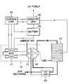
- FIG. 1is a block diagram of a distributed-power-generation system using a fuel cell according to an embodiment of the present invention.
- the distributed-power-generation systemcomprises a fuel cell 20 , a turbine generation unit 10 , a control unit 30 , and an inverter unit 40 .
- the fuel cell 20produces current and a high-temperature gas through an electric chemical reaction of hydrogen and oxygen.
- the high-temperature gas produced by the fuel cell 20is supplied to the turbine generation unit 10 .
- the turbine generation unit 10comprises a motor/generator unit 11 , a compressor 12 , and a turbine 13 .
- the motor/generator unit 11including a stator and a rotor acts as a motor in a starting mode of the turbine generation unit 10 , and as a generator in a generating mode of the turbine generation unit 10 .
- the compressor 12 , the turbine 13 , and the motor/generator unit 11form a single rotation axis.
- the motor/generator unit 11rotates in the starting mode and rotates an impeller of the compressor 12 .
- the compressor 12takes in external air and supplies the compressed air to the fuel cell 20 .
- the high-temperature gas produced by the fuel cell 20is supplied to and rotates the turbine 13 , thereby allowing the motor/generator unit 11 to function as a generator.
- DC power produced by the fuel cell 20 and AC power produced by the motor/generator unit 11are supplied to a three-phase power system through the inverter unit 40 .
- the inverter unit 40converts the AC power produced by the motor/generator unit 11 into DC power, adds the converted AC power to the DC power produced by the fuel cell 20 , converts the added AC/DC power into AC power, and discharges the converted AC power to a three-phase power system.
- the control unit 30contains a sensor (not shown) that senses a rotation speed of the rotation axis of the motor/generator unit 11 .
- the control unit 30may use separate means for measuring the rotation speed such as an encoder.
- the control unit 30measures the rotation speed of the rotation axis of the motor/generator unit 11 , and controls a current supplied to the motor/generator unit 11 by comparing the rotation speed with a predefined reference speed.
- the motor/generator unit 11acts as a motor in the starting mode, and is supplied with a small quantity of current in the generating mode.
- the motor/generator unit 11produces the small load in the opposite direction of rotation of the rotation axis while being supplied with the small quantity of current. That is, the motor/generator unit 11 produces the small load in the opposite direction of a rotation power of the rotation axis by the high-temperature gas supplied to the turbine 13 .
- the motor/generator unit 11reduces the rotation speed by increasing the current supplied by the control unit 30 and increasing the load in the opposite direction of rotation of the rotation axis.
- the motor/generator unit 11increases the rotation speed by reducing the current supplied by the control unit 30 and reducing the load in the opposite direction of rotation of the rotation axis.
- the air supplied to the fuel cell 20is preheated by a high-temperature liquid discharged through the turbine 13 in order to improve the efficiency of the distributed-power-generation system.
- the distributed-power-generation systemcomprises a recuperator 60 that heats the air supplied to the fuel cell 20 using high-temperature liquid discharged through the turbine 13 .
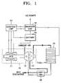
- FIG. 2is a block diagram of the inverter unit 40 shown in FIG. 1 .
- the inverter unit 40comprises a rectification circuit 41 , a smoothing circuit 42 , a DC/DC converter 43 , and a main inverter 44 .
- the rectification circuit 41converts the AC power produced by the motor/generator unit 11 into DC power.
- the smoothing circuit 42is used to uniform ripple produced by the rectification circuit 41 .
- the DC current passing through the smoothing circuit 42 along with the DC current produced by the fuel cell 20is supplied to the DC/DC converter 43 , converted into voltage necessary for the DC/DC converter 43 , converted into AC current in the main inverter 44 , and supplied to the three-phase power system.
- a chargeable battery 50is connected to the DC/DC converter 43 of the inverter unit 40 .
- the battery 50is charged with a part of a current supplied to the DC/DC converter 43 , and supplies current for the motor/generator unit 11 by the control unit 30 .
- the smoothing circuit 42comprising one or more capacitors makes uniform a DC wave by charging and discharging the capacitor.
- the capacitor contained in the smoothing circuit 42can be damaged due to excessive overcharge.
- the main inverter 44measures a voltage at both ends of the capacitor, compares the measured voltage of the capacitor with a predefined reference voltage, and discharges a current to the three-phase power system when the measured voltage exceeds a limit voltage of the capacitor.
- the distributed-power-generation systemquickly restores the rotation speed of the motor/ generator unit to the reference speed.
- the distributed-power-generation systemdischarges a current to the three-phase power system, thereby preventing the capacitor from being damaged.
Landscapes
- Engineering & Computer Science (AREA)
- Chemical & Material Sciences (AREA)
- Mechanical Engineering (AREA)
- General Engineering & Computer Science (AREA)
- Power Engineering (AREA)
- Combustion & Propulsion (AREA)
- Chemical Kinetics & Catalysis (AREA)
- General Chemical & Material Sciences (AREA)
- Fuel Cell (AREA)
- Control Of Eletrric Generators (AREA)
Abstract
Description
Claims (8)
Priority Applications (1)
| Application Number | Priority Date | Filing Date | Title |
|---|---|---|---|
| US11/820,186US7358622B2 (en) | 2004-10-01 | 2007-06-18 | Distributed power generation system using a fuel cell and a method of controlling the same |
Applications Claiming Priority (2)
| Application Number | Priority Date | Filing Date | Title |
|---|---|---|---|
| KR10-2004-0078261 | 2004-10-01 | ||
| KR1020040078261AKR101070906B1 (en) | 2004-10-01 | 2004-10-01 | Distributed power generation system and control method for the same |
Related Child Applications (1)
| Application Number | Title | Priority Date | Filing Date |
|---|---|---|---|
| US11/820,186DivisionUS7358622B2 (en) | 2004-10-01 | 2007-06-18 | Distributed power generation system using a fuel cell and a method of controlling the same |
Publications (2)
| Publication Number | Publication Date |
|---|---|
| US20060071477A1 US20060071477A1 (en) | 2006-04-06 |
| US7250690B2true US7250690B2 (en) | 2007-07-31 |
Family
ID=36124817
Family Applications (2)
| Application Number | Title | Priority Date | Filing Date |
|---|---|---|---|
| US11/185,183Expired - LifetimeUS7250690B2 (en) | 2004-10-01 | 2005-07-20 | Distributed power generation system using a fuel cell and a method of controlling the same |
| US11/820,186Expired - LifetimeUS7358622B2 (en) | 2004-10-01 | 2007-06-18 | Distributed power generation system using a fuel cell and a method of controlling the same |
Family Applications After (1)
| Application Number | Title | Priority Date | Filing Date |
|---|---|---|---|
| US11/820,186Expired - LifetimeUS7358622B2 (en) | 2004-10-01 | 2007-06-18 | Distributed power generation system using a fuel cell and a method of controlling the same |
Country Status (3)
| Country | Link |
|---|---|
| US (2) | US7250690B2 (en) |
| KR (1) | KR101070906B1 (en) |
| CN (1) | CN1756025B (en) |
Cited By (4)
| Publication number | Priority date | Publication date | Assignee | Title |
|---|---|---|---|---|
| US20070241722A1 (en)* | 2004-10-01 | 2007-10-18 | Samsung Techwin Co., Ltd. | Distributed power generation system using a fuel cell and a method of controlling the same |
| US20140091736A1 (en)* | 2011-06-28 | 2014-04-03 | Shenzhen Skd Technology Industrial Limited | Electric vehicle |
| US20140349808A1 (en)* | 2013-05-21 | 2014-11-27 | National Tsing Hua University | Hybrid transportation apparatus having fuel cell and air engine |
| US20180051584A1 (en)* | 2015-03-23 | 2018-02-22 | Aurelia Turbines Oy | Two-spool gas turbine arrangement |
Families Citing this family (17)
| Publication number | Priority date | Publication date | Assignee | Title |
|---|---|---|---|---|
| US7695839B2 (en)* | 2006-10-16 | 2010-04-13 | Gm Global Technology Operations, Inc. | Method for improved power up-transient response in the fuel cell system |
| DE102007002385A1 (en)* | 2007-01-10 | 2008-07-24 | Bundesdruckerei Gmbh | Document with an optical transmitter |
| JP5125199B2 (en)* | 2007-04-20 | 2013-01-23 | トヨタ自動車株式会社 | Engine start control device for hybrid vehicle |
| DE102008039449A1 (en)* | 2008-08-25 | 2010-03-04 | Rheinisch-Westfälische Technische Hochschule Aachen | Emission-free Karftwerk |
| US8206859B2 (en)* | 2008-12-16 | 2012-06-26 | GM Global Technology Operations LLC | Method of stabilizing a stack after completing startup, without extending the startup time |
| IN2012DN01903A (en) | 2009-08-07 | 2015-07-24 | Shimizu Construction Co Ltd | |
| JP5700237B2 (en)* | 2010-07-08 | 2015-04-15 | 株式会社Ihi | Waste heat recovery device |
| CN103283114B (en)* | 2011-03-31 | 2016-10-26 | 洪瑞桐 | Energy management and energy production systems |
| WO2013040720A1 (en) | 2011-09-21 | 2013-03-28 | Cyoris Ag | Arrangement for converting mechanical energy into electric energy |
| KR101362580B1 (en)* | 2012-01-17 | 2014-02-14 | 세종공업 주식회사 | Fuel cell system and start-up method thereof |
| KR101515709B1 (en) | 2013-10-08 | 2015-04-27 | 주식회사 삼천리 | Control Method of distributed and integrated generation system |
| KR101667036B1 (en)* | 2016-03-21 | 2016-10-20 | 윈월드(주) | torque controlling device and methods for generator of small hydro power |
| DE102018201233A1 (en)* | 2017-04-18 | 2018-10-18 | Ford Global Technologies, Llc | Motor vehicle with a fuel cell |
| CN108172861A (en)* | 2018-01-17 | 2018-06-15 | 佛山科学技术学院 | A pulsed hydrogen fuel cell electric auxiliary turbocharger power generation device |
| CN108172879A (en)* | 2018-01-17 | 2018-06-15 | 佛山科学技术学院 | A temperature-controlled power generation device based on fuel cells and lithium batteries |
| CN108365657B (en)* | 2018-03-20 | 2020-06-19 | 北京小米移动软件有限公司 | Method, device and storage medium for controlling charging current |
| US12326118B2 (en)* | 2022-09-16 | 2025-06-10 | General Electric Company | Gas turbine engines with a fuel cell assembly |
Citations (16)
| Publication number | Priority date | Publication date | Assignee | Title |
|---|---|---|---|---|
| US4084038A (en)* | 1974-12-19 | 1978-04-11 | Scragg Robert L | Electrical power generation and storage system |
| US4185203A (en)* | 1977-04-23 | 1980-01-22 | Nissan Motor Company, Limited | Closed loop rotational speed control system for twin-shaft type gas turbine electric generator |
| US4281256A (en)* | 1979-05-15 | 1981-07-28 | The United States Of America As Represented By The United States Department Of Energy | Compressed air energy storage system |
| US4757686A (en)* | 1985-08-30 | 1988-07-19 | Isuzu Motors Limited | Control system for supercharger in internal combustion engine |
| US4828940A (en)* | 1987-08-27 | 1989-05-09 | International Fuel Cells Corporation | Fuel cell power plant with increased reactant pressures |
| US5225712A (en) | 1991-02-01 | 1993-07-06 | U.S. Windpower, Inc. | Variable speed wind turbine with reduced power fluctuation and a static VAR mode of operation |
| US5391925A (en)* | 1993-09-10 | 1995-02-21 | Trigen Energy Corporation | Prime mover driven compressor/chiller with motor on common shaft for large cooling systems |
| US5678647A (en)* | 1994-09-07 | 1997-10-21 | Westinghouse Electric Corporation | Fuel cell powered propulsion system |
| US5811201A (en)* | 1996-08-16 | 1998-09-22 | Southern California Edison Company | Power generation system utilizing turbine and fuel cell |
| US6201312B1 (en)* | 1998-02-17 | 2001-03-13 | Toyota Jidosha Kabushiki Kaisha | Drive control system for hybrid vehicles |
| US6380637B1 (en)* | 1996-09-19 | 2002-04-30 | Ztek Corporation | Off-board station and an electricity exchanging system suitable for use with a mobile vehicle power system |
| US6380640B1 (en)* | 1999-10-07 | 2002-04-30 | Toyota Jidosha Kabushiki Kaisha | Method of controlling power output apparatus |
| WO2002037587A2 (en) | 2000-10-30 | 2002-05-10 | Ztek Corporation | A hybrid electrical power system employing fluid regulating elements for controlling various operational parameters of the system |
| US6559551B2 (en) | 2000-09-23 | 2003-05-06 | Ballard Power Systems Ag | Starter device for fuel cell system |
| US6616424B2 (en)* | 2000-08-25 | 2003-09-09 | General Motors Corporation | Drive system and method for the operation of a fuel cell system |
| US6628006B2 (en)* | 2001-05-03 | 2003-09-30 | Ford Motor Company | System and method for recovering potential energy of a hydrogen gas fuel supply for use in a vehicle |
Family Cites Families (6)
| Publication number | Priority date | Publication date | Assignee | Title |
|---|---|---|---|---|
| US5529747A (en)* | 1993-11-10 | 1996-06-25 | Learflux, Inc. | Formable composite magnetic flux concentrator and method of making the concentrator |
| JP4244399B2 (en)* | 1998-05-14 | 2009-03-25 | トヨタ自動車株式会社 | FUEL CELL SYSTEM, ELECTRIC VEHICLE HAVING THE SAME AND FUEL CELL SYSTEM START-UP CONTROL METHOD |
| JP2002218657A (en) | 2001-01-23 | 2002-08-02 | Toshiba Corp | Power generation system |
| JP2002281672A (en) | 2001-03-23 | 2002-09-27 | Aisin Seiki Co Ltd | Control device for household fuel cell system |
| US6717282B1 (en)* | 2002-07-03 | 2004-04-06 | William J. Maxwell | Combined motor and generator dynamometer system |
| KR101070906B1 (en)* | 2004-10-01 | 2011-10-06 | 설승기 | Distributed power generation system and control method for the same |
- 2004
- 2004-10-01KRKR1020040078261Apatent/KR101070906B1/ennot_activeExpired - Fee Related
- 2005
- 2005-07-20USUS11/185,183patent/US7250690B2/ennot_activeExpired - Lifetime
- 2005-08-29CNCN2005100994145Apatent/CN1756025B/ennot_activeExpired - Fee Related
- 2007
- 2007-06-18USUS11/820,186patent/US7358622B2/ennot_activeExpired - Lifetime
Patent Citations (16)
| Publication number | Priority date | Publication date | Assignee | Title |
|---|---|---|---|---|
| US4084038A (en)* | 1974-12-19 | 1978-04-11 | Scragg Robert L | Electrical power generation and storage system |
| US4185203A (en)* | 1977-04-23 | 1980-01-22 | Nissan Motor Company, Limited | Closed loop rotational speed control system for twin-shaft type gas turbine electric generator |
| US4281256A (en)* | 1979-05-15 | 1981-07-28 | The United States Of America As Represented By The United States Department Of Energy | Compressed air energy storage system |
| US4757686A (en)* | 1985-08-30 | 1988-07-19 | Isuzu Motors Limited | Control system for supercharger in internal combustion engine |
| US4828940A (en)* | 1987-08-27 | 1989-05-09 | International Fuel Cells Corporation | Fuel cell power plant with increased reactant pressures |
| US5225712A (en) | 1991-02-01 | 1993-07-06 | U.S. Windpower, Inc. | Variable speed wind turbine with reduced power fluctuation and a static VAR mode of operation |
| US5391925A (en)* | 1993-09-10 | 1995-02-21 | Trigen Energy Corporation | Prime mover driven compressor/chiller with motor on common shaft for large cooling systems |
| US5678647A (en)* | 1994-09-07 | 1997-10-21 | Westinghouse Electric Corporation | Fuel cell powered propulsion system |
| US5811201A (en)* | 1996-08-16 | 1998-09-22 | Southern California Edison Company | Power generation system utilizing turbine and fuel cell |
| US6380637B1 (en)* | 1996-09-19 | 2002-04-30 | Ztek Corporation | Off-board station and an electricity exchanging system suitable for use with a mobile vehicle power system |
| US6201312B1 (en)* | 1998-02-17 | 2001-03-13 | Toyota Jidosha Kabushiki Kaisha | Drive control system for hybrid vehicles |
| US6380640B1 (en)* | 1999-10-07 | 2002-04-30 | Toyota Jidosha Kabushiki Kaisha | Method of controlling power output apparatus |
| US6616424B2 (en)* | 2000-08-25 | 2003-09-09 | General Motors Corporation | Drive system and method for the operation of a fuel cell system |
| US6559551B2 (en) | 2000-09-23 | 2003-05-06 | Ballard Power Systems Ag | Starter device for fuel cell system |
| WO2002037587A2 (en) | 2000-10-30 | 2002-05-10 | Ztek Corporation | A hybrid electrical power system employing fluid regulating elements for controlling various operational parameters of the system |
| US6628006B2 (en)* | 2001-05-03 | 2003-09-30 | Ford Motor Company | System and method for recovering potential energy of a hydrogen gas fuel supply for use in a vehicle |
Cited By (7)
| Publication number | Priority date | Publication date | Assignee | Title |
|---|---|---|---|---|
| US20070241722A1 (en)* | 2004-10-01 | 2007-10-18 | Samsung Techwin Co., Ltd. | Distributed power generation system using a fuel cell and a method of controlling the same |
| US7358622B2 (en)* | 2004-10-01 | 2008-04-15 | Samsung Techwin Co., Ltd. | Distributed power generation system using a fuel cell and a method of controlling the same |
| US20140091736A1 (en)* | 2011-06-28 | 2014-04-03 | Shenzhen Skd Technology Industrial Limited | Electric vehicle |
| US9776492B2 (en)* | 2011-06-28 | 2017-10-03 | Shenzhen Skd Technology Industrial Limited | Electric vehicle |
| US20140349808A1 (en)* | 2013-05-21 | 2014-11-27 | National Tsing Hua University | Hybrid transportation apparatus having fuel cell and air engine |
| US20180051584A1 (en)* | 2015-03-23 | 2018-02-22 | Aurelia Turbines Oy | Two-spool gas turbine arrangement |
| US10626746B2 (en)* | 2015-03-23 | 2020-04-21 | Aurelia Turbines Oy | Controllable two-spool gas turbine arrangement |
Also Published As
| Publication number | Publication date |
|---|---|
| KR20060029354A (en) | 2006-04-06 |
| US20060071477A1 (en) | 2006-04-06 |
| CN1756025B (en) | 2012-03-21 |
| KR101070906B1 (en) | 2011-10-06 |
| US20070241722A1 (en) | 2007-10-18 |
| US7358622B2 (en) | 2008-04-15 |
| CN1756025A (en) | 2006-04-05 |
Similar Documents
| Publication | Publication Date | Title |
|---|---|---|
| US7358622B2 (en) | Distributed power generation system using a fuel cell and a method of controlling the same | |
| US7061211B2 (en) | Gas turbine generating apparatus | |
| KR100603245B1 (en) | Hybrid power unit | |
| EP0963035A3 (en) | Turbogenerator/motor control system | |
| US11053013B2 (en) | Unit for generating non-propulsive electrical power | |
| US8575888B2 (en) | Wind-driven electricity generation system of type having storage battery and device for controlling charge and discharge of storage battery | |
| JP4951403B2 (en) | Wind power generation control system and control method thereof | |
| KR20160072975A (en) | Power generation system using fuel cell electric vehicle and control method thereof | |
| JP3758359B2 (en) | Wind power output stabilization method and apparatus | |
| CN103066676B (en) | Fuel cell power supply device and power supply system | |
| KR20220153018A (en) | AC-DC converter for electrolysis | |
| JP3950706B2 (en) | Grid interconnection system | |
| JPH11299295A (en) | Control of wind power generator | |
| KR101136377B1 (en) | Wind-disel hybrid power supply system using common inverter | |
| CN111463824B (en) | Movable power generation system | |
| JP2003214320A (en) | Wind power generating device | |
| KR101550626B1 (en) | Power supply apparatus of fuel cell vehicle | |
| KR20060093539A (en) | Fuel cell system and driving method thereof | |
| JP2002317750A (en) | Control method of generator system by combination of wind power generation with diesel power generation, and generator system | |
| JP3539248B2 (en) | Power generation system | |
| NL2024916B1 (en) | AC to DC converter for electrolysis | |
| RU2353799C1 (en) | Method for operation of autonomous wind-electric station | |
| CN118300147A (en) | Energy storage module of closed-loop energy conversion system | |
| KR200312426Y1 (en) | utilize the wind to Auto Battery Charger | |
| Prasad et al. | GRID-BASED VARIABLE SPEED WIND ENERGY CONVERSION SYSTEM POWER QUALITY IMPROVEMENT |
Legal Events
| Date | Code | Title | Description |
|---|---|---|---|
| AS | Assignment | Owner name:SAMSUNG TECHWIN CO., LTD., KOREA, REPUBLIC OF Free format text:ASSIGNMENT OF ASSIGNORS INTEREST;ASSIGNOR:YANG, HYUN-SUP;REEL/FRAME:016634/0693 Effective date:20050711 | |
| STCF | Information on status: patent grant | Free format text:PATENTED CASE | |
| FEPP | Fee payment procedure | Free format text:PAYOR NUMBER ASSIGNED (ORIGINAL EVENT CODE: ASPN); ENTITY STATUS OF PATENT OWNER: LARGE ENTITY | |
| FPAY | Fee payment | Year of fee payment:4 | |
| FEPP | Fee payment procedure | Free format text:PAYOR NUMBER ASSIGNED (ORIGINAL EVENT CODE: ASPN); ENTITY STATUS OF PATENT OWNER: LARGE ENTITY Free format text:PAYER NUMBER DE-ASSIGNED (ORIGINAL EVENT CODE: RMPN); ENTITY STATUS OF PATENT OWNER: LARGE ENTITY | |
| FPAY | Fee payment | Year of fee payment:8 | |
| AS | Assignment | Owner name:HANWHA TECHWIN CO., LTD., KOREA, DEMOCRATIC PEOPLE Free format text:CHANGE OF NAME;ASSIGNOR:SAMSUNG TECHWIN CO., LTD.;REEL/FRAME:036714/0757 Effective date:20150629 | |
| AS | Assignment | Owner name:HANWHA TECHWIN CO., LTD., KOREA, REPUBLIC OF Free format text:CORRECTIVE ASSIGNMENT TO CORRECT THE RECEIVING PARTY ADDRESS PREVIOUSLY RECORDED AT REEL: 036714 FRAME: 0757. ASSIGNOR(S) HEREBY CONFIRMS THE CHANGE OF NAME;ASSIGNOR:SAMSUNG TECHWIN CO., LTD.;REEL/FRAME:037072/0008 Effective date:20150629 | |
| MAFP | Maintenance fee payment | Free format text:PAYMENT OF MAINTENANCE FEE, 12TH YEAR, LARGE ENTITY (ORIGINAL EVENT CODE: M1553); ENTITY STATUS OF PATENT OWNER: LARGE ENTITY Year of fee payment:12 |