US7250022B2 - Exercise device with centrally mounted resistance rod - Google Patents
Exercise device with centrally mounted resistance rodDownload PDFInfo
- Publication number
- US7250022B2 US7250022B2US10/173,515US17351502AUS7250022B2US 7250022 B2US7250022 B2US 7250022B2US 17351502 AUS17351502 AUS 17351502AUS 7250022 B2US7250022 B2US 7250022B2
- Authority
- US
- United States
- Prior art keywords
- resilient elongate
- cable
- elongate member
- resistance
- coupled
- Prior art date
- Legal status (The legal status is an assumption and is not a legal conclusion. Google has not performed a legal analysis and makes no representation as to the accuracy of the status listed.)
- Expired - Fee Related, expires
Links
Images


Classifications
- A—HUMAN NECESSITIES
- A63—SPORTS; GAMES; AMUSEMENTS
- A63B—APPARATUS FOR PHYSICAL TRAINING, GYMNASTICS, SWIMMING, CLIMBING, OR FENCING; BALL GAMES; TRAINING EQUIPMENT
- A63B21/00—Exercising apparatus for developing or strengthening the muscles or joints of the body by working against a counterforce, with or without measuring devices
- A63B21/02—Exercising apparatus for developing or strengthening the muscles or joints of the body by working against a counterforce, with or without measuring devices using resilient force-resisters
- A63B21/045—Exercising apparatus for developing or strengthening the muscles or joints of the body by working against a counterforce, with or without measuring devices using resilient force-resisters having torsion or bending or flexion element
- A—HUMAN NECESSITIES
- A63—SPORTS; GAMES; AMUSEMENTS
- A63B—APPARATUS FOR PHYSICAL TRAINING, GYMNASTICS, SWIMMING, CLIMBING, OR FENCING; BALL GAMES; TRAINING EQUIPMENT
- A63B21/00—Exercising apparatus for developing or strengthening the muscles or joints of the body by working against a counterforce, with or without measuring devices
- A63B21/02—Exercising apparatus for developing or strengthening the muscles or joints of the body by working against a counterforce, with or without measuring devices using resilient force-resisters
- A63B21/026—Bars; Tubes; Leaf springs
Definitions
- the present inventionrelates to exercise devices. More specifically, the present invention relates to an exercise device having resilient elongate members for providing resistance against which a user can exercise.
- Multi-function exercise machineshave been developed in response to this demand. Multi-function exercise machines are often adapted to be convenient to operate and store, while still providing the range of exercises necessary to provide effective all around fitness.
- One type of conventional multi-function exercise machineutilizes a stack of weights to provide resistance needed by users during exercise. A user repetitively raises some, or all, of the weight stack. The force of gravity provides the resistance needed to allow the user to exercise. However, due to the mass of the weights, these machines are heavy and can be difficult for a home user to move.
- Exercise machinesthat use flexible members to provide resistance have been developed as an alternative to weight stack machines.
- One such device available in the marketincorporates two sets of flexible rods of varying resistance.
- the bottom end of each set of rodsis attached to the base of the machine with the rods extending vertically upwards therefrom.
- a cableis attached to the top end of each set of rods by means of a large hook that is threaded through loops at the top end of each rod.
- the exercise machine of the present inventionhas a support assembly to which are coupled a plurality of resilient elongate members, a cable and pulley system, and, optionally, a bench.
- the exercise machineis adapted to allow a user to exercise using the resistance provided by the flexible, resilient, elongate members.
- the configuration of the exercise machineprovides many benefits including, for example: exercise rods positioned on a fulcrum at the intermediate portion of the rods, a capture device enabling one handed addition and removal of resistance rods, movement of both ends of the resilient elongate members when the cable is drawn, equivalent resistance on both ends of the cable independently of whether equal amounts of resistance are provided at the cable ends, a cable and pulley system providing compounding effects of the resistance, rotatable resilient elongate members allowing convenient storage of the device, and a plurality of additional features and benefits.
- a resilient elongate member assemblycomprises a plurality of elongate members positioned on a fulcrum.
- horizontally oriented resilient elongate members of the present inventionare centrally positioned on the fulcrum.
- the resilient elongate membersflex when a force is applied to them, and are used to provide resistance for the user to exercise against.
- the useris able to adjust the amount of resistance used during exercise by using a pair of capture devices to add or delete resilient elongate members utilized to provide resistance.
- Theseare coupled to each end of a resilient elongate member and are adapted to allow the user to selectively capture resilient elongate members to increase or decrease the resistance.
- the capture deviceis adapted to allow the user to add or delete resilient elongate members using one hand.
- the cable and pulley systemcomprises a plurality of pulleys and one or more cables.
- the cable and pulley systemis configured such that a pulley is coupled to each end of a resilient elongate member assembly.
- a cableis adapted to be threaded through these pulleys.
- Additional pulleysare used to alter the direction of the cable to accommodate traditional exercise positions.
- Handles and other exercise accessoriesare adapted to be selectively coupled to the cable and pulley system to allow a user to utilize the resistance provided by the resilient elongate members.
- the resilient elongate membersflex downwards following the path of the cable to provide resistance. Further pulleys are cables can be coupled to the machine to enable a wide variety of exercise to be undertaken.
- the cable and pulley system of the present inventionallows the user to take a long stroke due to the mechanical advantage provided by the cable and pulley system.
- the cable and pulley systemalso eliminates the need to capture the same amount of resistance at each end of the resilient elongate member assembly.
- the usercan benefit from a bench as source of balance and stability when doing exercises.
- a leg exercise unitis attached to the bench.
- the leg exercise unitcan be connected to the cable and pulley system, thus allowing the user to undertake a variety of leg exercises against the resistance of the resilient elongate members.
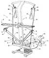
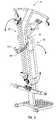
- FIG. 1illustrates a perspective front view of an exercise machine according to one embodiment of the present invention
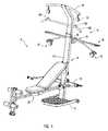
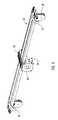
- FIG. 2is a perspective view of the back of the exercise machine of FIG. 1 featuring cables of the cable and pulley system and having alternative pulley brackets mounted onto a lower, horizontal member of the frame;
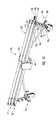
- FIG. 3Aillustrates a perspective view of a resilient elongate member assembly of the exercise machine the present invention
- FIG. 3Billustrates a top view of the resilient elongate member assembly of FIG. 3A ;
- FIG. 4illustrates a perspective view of a capture device that is configured to capture the ends of one or more resilient elongate members according to one embodiment of the present invention
- FIG. 5Aillustrates a perspective view of an alternative embodiment of a resilient elongate member assembly of the present invention featuring vertically stacked elongate members;
- FIG. 5Billustrates a the assembly of FIG. 5A ;
- FIG. 5Cillustrates a perspective view of another alternative embodiment of a vertically stacked resilient elongate member assembly
- FIG. 6illustrates a resilient elongate member assembly of an exercise machine of the present invention showing the ends of multiple resilient elongate members held by one of the capture devices of the assembly;
- FIG. 7is a schematic perspective view of one embodiment of the cable and pulley system of an exercise machine of the present invention.
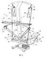
- FIG. 8is a perspective view illustrating the exercise machine of the present invention in which the resilient elongate members and bench are in a storage position (device shown without cables);
- FIG. 9illustrates a resilient elongate member assembly having a fulcrum which is rotatable, such that the resilient elongate member assembly is movable into a substantially horizontal use position or a substantially vertical storage position.
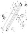
- FIG. 10is a view illustrating the resilient elongate member assembly of the present invention, including the rotatable fulcrum components according to one embodiment of the present invention.
- Exercise machine 10 of FIG. 1includes a support assembly 11 comprising (i) a frame 12 and (ii) a fulcrum 30 .
- Support assembly 11provides a mechanism for integrating components of the exercise machine 10 , the components including, for example, a plurality of resilient elongate members 28 , a cable and pulley system 24 (cables not shown in FIG. 1 ), and, optionally, a bench 26 .
- Frame 12comprises a post 14 , a base member 16 which contacts a support surface (e.g., a floor or the ground), a lower horizontal member 18 and an upper horizontal member 20 .
- Post 14provides a rigid upright for connecting various components of the present invention.
- Base member 16is coupled to the bottom end of post 14 and may include wheels thereon for convenient moving of device 10 .
- Base member 16provides a bottom support for post 14 .
- Lower horizontal member 18is coupled to post 14 .
- Upper horizontal member 20is coupled to the upper portion of post 14 .
- Frame 12can include a variety of components combined in a variety of configurations without departing from the scope and spirit of the present invention.
- frame 12can be configured such that one or more of the referenced components is not present.
- upper horizontal member 20which facilitates overhead exercises, is not provided on a machine designed only for low reach exercises.
- the framecomprises another vertical surface such as a wall or pole.
- a cable and pulley systeme.g., system 24
- a fulcrume.g., fulcrum 30
- a surfacee.g., a pole or wall
- a frame of substantially horizontal orientationcan also be used.
- a resilient elongate member assembly 22 of the present inventioncomprises: (i) a plurality of resilient elongate members 28 ; (ii) a fulcrum 30 ; and (iii) capture devices 32 , 34 .
- the plurality of resilient elongate members 28 of the present inventionare positioned on fulcrum 30 .
- a resilient elongate member assembly of the present inventioncomprises a plurality of resilient elongate members coupled integrally to a fulcrum, which is coupled to the frame.
- a single resilient elongate memberis employed.
- a cable and pulley system 24is also coupled to frame 12 .
- the cable(s) of the system 24are shown, for example, in FIGS. 2 and 7 .
- Cable and pulley system 24provides a mechanism for utilizing the resistance provided by the plurality of resilient elongate members 28 .
- the cable and pulley system 24is selectively coupled to frame 12 and at least one of the plurality of resilient elongate members 28 .
- the exercise machine 10includes a bench 26 coupled to upstanding member 14 of frame 12 .
- Bench 26has an adjustable seat 106 and a leg exercise unit 108 .
- Leg lever 110 of leg exercise unit 108may be attached to cable and pulley system 24 by cable 114 .
- Cable 114is fixed at a first end to leg lever 110 , is threaded over pulley 112 , and can be selectively coupled at its second end to first end 90 a or second end 90 b of cable 90 .
- the second end of cable 114splits into or couples to dual cables, each dual cable end being coupleable to a corresponding end 90 a or 90 b of cable 90 .
- force exerted on leg lever 110is transmitted through cable 114 and cable 90 , causing the captured resilient elongate members to flex.
- exercise device 10A variety of components and configurations of exercise device 10 can be utilized without departing from the scope or spirit of the present invention.
- a bench unitis not included as part of the exercise machine, or other components not previously discussed are utilized.
- the cable and pulley system 24comprises pulleys 36 , 38 , 76 , 78 , 80 , 82 , 84 , 86 , and 88 and cables 90 , 96 , 98 , and 114 .
- a single cablemay be substituted for cables 90 , 96 , and 98 .
- Pulleys 76 , 78 , and 80are coupled to upstanding member 14 .
- Pulleys 82 , 84are coupled to lower horizontal member 18 .
- Pulleys 86 , 88are coupled to upper horizontal member 20 .
- Pulleys 36 , 38are coupled to resilient elongate members 28 .
- Cable 90is coupled to pulleys 76 , 78 , 80 , 82 , 84 , 36 , 38 .
- Cable 90comprises a first end 90 a , a second end 90 b , and an intermediate portion 90 c .
- the intermediate portion 90 cis the portion of cable 90 threaded through pulleys 76 , 78 , 80 , 82 , 84 , 36 , and 38 .
- Handles 92 , 94are shown coupled to cables 96 , 98 , (e.g., for lat pull down exercises) but may optionally be coupled directly to opposing ends 90 a , 90 b of cable 90 for a variety of other exercises if desired.
- First end 90 a and second end 90 b of cable 90allow users to exert a force on resilient elongate members 28 .
- interaction between intermediate portion 90 c and pulleys 36 and 38displaces pulleys 36 and 38 .
- the coupling of pulleys 36 and 38 to the ends of the one or more of the plurality of resilient elongate members 28 , and the associated configuration of cable 90is such that movement of the first end 90 a or second end 90 b of cable 90 causes movement of both ends of one or more of the plurality of resilient elongate members.
- movement of the first end 90 a or second end 90 b of cable 90causes movement of both ends of the resilient elongate member shown as being flexed in FIG. 2 .
- One or both ends of another resilient elongate membercan be captured by one or more respective capture devices 32 shown in FIG. 2 in order to increase resistance (see FIG. 6 ).
- either one end or both ends of a resilient elongate membermay be captured in order to increase resistance.
- Pulleys 82 and 84 of FIG. 2may be coupled to the lower horizontal member of frame 14 through a variety of different methods, such as through the use of (i) an eyebolt coupled to the frame and (ii) a u-shaped bracket or eyebolt coupled thereto, which is in turn coupled to the respective pulley bracket.
- the pulleysare coupled to the frame through the use of a pulley bracket coupled to a first tube (or pin), which pivots within a second tube coupled to the frame.
- Ballstops 91 , 93also enable a degree of tension in cable and pulley system 24 .
- Cable 90is adapted to be moved by the user against the resistance of the resilient elongate members.
- the first end 90 a of cable 90can be selectively coupled to detachable handle 92 or cable 96 .
- the second end 90 b of cable 90can be selectively coupled to detachable handle 94 or cable 98 .
- This selective couplingallows the user to attach detachable handle 92 to first end 90 a and attach detachable handle 94 to second end 90 b and then move detachable handles 92 , 94 in a direction away from pulleys 82 , 84 .
- the usercan then carry out a variety of low reach exercises.
- the usercan assemble the cable and pulley system and exercise on the device by attaching first end 96 a of cable 96 to first end 90 a of cable 90 ; attaching first end 98 a of cable 98 to second end 90 b of cable 90 ; coupling cable 96 to pulley 86 ; coupling cable 98 to pulley 88 ; attaching detachable handle 92 to second end 96 b of cable 96 ; attaching detachable handle 94 to second end 98 b of cable 98 ; and moving detachable handles 92 , 94 in a direction away from pulleys 86 , 88 .
- handles 92 , 94may be attached directly to cable 90 .
- the usermay attach an overhead bar 100 ( FIG. 1 ) to cable 90 or to cables 96 , 98 at second ends 96 b , 98 b using eyelets 102 , 104 respectively.
- an overhead bar 100FIG. 1
- resilient elongate member assembly 22which comprises fulcrum 30 and resilient elongate members 28 and capture devices 34 .
- the resilient elongate member assemblycomprises a single elongate member comprising an intermediate portion and a plurality of flexible resilient elongate fingers extending from opposing ends of the intermediate portion.
- the intermediate portionis integral with the fingers.
- the resilient elongate member assemblymay be molded as a single integral piece.
- the intermediate portionfor example, may be directly or indirectly coupled to a frame.
- fulcrum 30is coupled to post 14 of frame 12 in part through the use of baseplate 14 .
- fulcrum 30 or another fulcrum of the present inventionis integrally coupled to the frame.
- the fulcrum of the present inventionmay be integrally or non-integrally coupled to the frame.
- the fulcrummay be immovably coupled to the frame or movably coupled to the frame.
- fulcrum 30is movably coupled to frame 14 .
- fulcrum 30allows the plurality of resilient elongate members 28 to be rotatable between a first position (e.g., substantially horizontal) for use and a second position (e.g., substantially vertical) for storage.
- fulcrum 30is movably coupled to upstanding member 14 .
- a locking assemblysuch as locking pin assembly 131 allows a user to selectively lock fulcrum 30 in a first position for use or in a second position for storage.
- the fulcrumis immovably affixed (e.g., integrally or non-integrally) to the frame.
- Resilient elongate members 42 , 44 , 46 , 48 , 50 , 52provide resistance against which the user can exercise.
- Each flexible, resilient elongate member 42 , 44 , 46 , 48 , 50 , 52has a first end 42 a , 44 a , 46 a , 48 a , 50 a , 52 a and a second end 42 b , 44 b , 46 b , 48 b , 50 b , 52 b that extend away from respective intermediate portions thereof.
- Each resilient elongate memberis comprised of a resilient material.
- the resilient elongate memberis comprised of nylon, although other materials are possible, such as wood laminates, steel leaf springs, fiberglass and/or acetal.
- the elongate membersmay further comprise a coating on the nylon material or other material employed, such as a protective coating, e.g., a polyolefin material, or a variety of other coatings which may provide a protective layer and/or an aesthetically pleasing appearance. However, such coatings are not required.
- the elongate memberscomprise a gripping/wear-resistance material 27 ( FIG. 3A ) at the tips thereof, which may comprise an ABS plastic material, for example.
- a number or other indiciacan be provided on the gripping/wear-resistance material 27 to identify the amount of resistance that is provided by each elongate member.
- the resilient elongate membersare adapted to provide a range of different amounts of resistance.
- the amount of resistance provided by resilient elongate members 42 , 44 , 46 , 48 , 50 , 52corresponds with the diameter of the resilient elongate member.
- resilient elongate members 46 , 44 , 42 , 48 , 50 , and 52may have diameters of 7 ⁇ 8 inch, 1 inch, 11/16 inch, 1 inch, 3 ⁇ 4 inch and 5 ⁇ 8 inch respectively, for example. 11 ⁇ 8 inch members may be vertically stacked above such members, for example. However, in alternative embodiments other diameters can be used.
- seven elongate membersor one, two, three, four, five, eight, nine, ten, or a vast number of possibilities of other members may be employed.
- all the resilient elongate membershave the same diameter.
- different resistance amountsare provided irrespective of the diameter of the resilient elongate members, e.g., by employing different materials.
- Resilient elongate member 42is shown in a flexed position in FIG. 3A . Coupled to resilient elongate member 42 at first end 42 a is a capture device 32 , which is in turn coupled to pulley 36 . Coupled to resilient elongate member 42 at second end 42 b is capture device 34 , which is in turn coupled to pulley 38 . In alternative embodiments, fewer or more pulleys can be coupled to the capture devices. In yet another embodiment, one or more resilient elongate members are coupled directly to resilient elongate members 28 .
- Capture device 32comprises a main body 54 , a first capture member 56 coupled to the main body 54 , a second capture member 58 coupled to the main body 54 , and a first tab 60 and a second tab 62 extending from respective capture members.
- Capture members 56 , 58are substantially horizontal in orientation.
- the main body 54is coupled lengthwise to resilient elongate member 42 .
- first capture member 56 and second capture member 58Extending outwards from main body 54 are first capture member 56 and second capture member 58 . Extending downwards from first capture member 56 is first tab 62 , and extending downwards from second capture member 58 is second tab 60 . As will be appreciated by those skilled in the art, capture devices with fewer or more capture members and tabs are possible.
- Main body 54may be coupled to a resilient elongate member by means of an upper aperture 64 , into which the resilient elongate member is inserted.
- Pulley 36is coupled to the main body 54 of capture device 32 by means of a pin 66 extending through the pulley bracket and a lower aperture of main body 54 .
- Pin 66allows pulley 36 to pivot in its coupling with main body 54 , while the machine is being used.
- the resilient elongate assembly 22 zcomprises a fulcrum 30 z , a plurality of resilient elongate members 28 z and two capture devices 32 z , 34 z .
- resilient elongate members 28 zare arranged in two rows 29 , 31 .
- capture device 32 zIn order to be able to capture row 31 of resilient elongate members 28 z , capture device 32 z has a pair of capture members 57 , 59 mounted on top of capture members 56 z , 58 z . Capture device 34 z is similarly configured. By having more resilient elongate members, the total amount of resistance that the user is able to select is increased.
- FIG. 5Cthere is shown yet another alternative embodiment of a resilient elongate member assembly 22 y .
- capture members 57 , 59are mounted on top of capture device 32 y such that capture member 57 and capture member 59 form openings facing the same direction. The openings are configured to capture resilient elongate members 45 and 47 .
- Capture members 57 , 59are mounted on top of capture members 56 y , 58 y .
- Capture device 34 yis similarly configured.
- resilient elongate members 45 and 47are positioned such that resilient elongate member 45 is placed immediately above resilient elongate member 47 .
- FIG. 6there is shown how capture devices 32 , 34 are used to capture resilient elongate members. It can be seen that resilient elongate members 44 , 48 have been captured at their first ends 44 a , 48 a by capture device 32 . The capturing of resilient elongate members 44 , 48 is accomplished by capture members 56 , 58 . Thus, it can be seen that first end 44 a of resilient elongate member 44 is captured underneath capture member 56 of capture device 32 . The resilient elongate members are prevented from horizontal movement by respective tabs 60 . 62 .
- resilient elongate members 44 , 48are subject to the force applied at pulley 36 and flex as a result of the application of force.
- the useris able to select the amount of resistance with which to exercise. The more resilient elongate members that are captured, the higher the resistance provided. In one embodiment, the amount of resistance depends on the diameter of the resilient elongate members captured. In an alternative embodiment, resilient elongate members of different materials can be used in the resilient elongate member assembly, and resistance can depend on the material of the resilient elongate members captured.
- Capture device 32allows a user to select and retain at least one end of resilient elongate member 44 .
- the userpresses downwards on first end 44 a and manipulates it around tab 62 or tab 60 to position an end 44 of the resilient elongate member 44 under a capture member 56 or 58 .
- first end 44 ais below capture device 32
- the userreleases first end 44 a .
- the resilience of the resilient elongate memberbiases the first end 44 a upward and under capture device 32 such that capture device 32 retains first end 44 a .
- the usercan then perform the same operation with the second end 44 b of member 44 and capture device 34 if the user desires to capture both ends of resilient elongate member 44 . However, only a single end may be captured if desired.
- capture device 32 of the present inventionis adapted to eliminate the need to thread the resilient elongate members 28 onto a hook-like device. Neither do the resilient elongate members 28 need to be configured to receive a hook-like device.
- the present inventionmerely requires that the user manipulate the end of the resilient elongate member under the capture device. In addition to simplifying adjustment of the resistance amount, the user can make such adjustments using only one hand. This allows the user to use both hands to capture two resilient elongate members at the one time, making the process of varying the resistance more efficient. Further, each hand can manipulate more than one resilient elongate member at once. In a preferred embodiment, the user can capture every resilient elongate member simultaneously using both hands. To release a resilient elongate member, the operation is performed in reverse. Again, the release of the resilient elongate members can be accomplished using only one hand.
- resilient elongate member 42is always affixed to the cable and pulley system, some resistance is always provided. From this starting point, any subsequent increase in resistance can be accomplished by capturing a resilient elongate member using one hand.
- resilient elongate members 28Once resilient elongate members 28 are captured, the resilient elongate members 28 can remain in a defined path as they flex. As a result, resilient elongate members 28 flex evenly.
- Fulcrum 30comprises an assembly that covers the top and bottom surfaces of an intermediate portion of elongate members.
- Fulcrum 30is configured such that one or both ends of a particular elongate member may be flexed.
- Fulcrummay be configured as a clamshell assembly (see, e.g., FIG. 10 ).
- the cable and pulley systemis adapted to convey resistance provided by one or more resilient elongate members.
- one or more cables of the cable and pulley systemare adapted to be coupled to a first and second point of resistance provided by the resilient elongate members.
- pulleys 36 , 38are essentially floating pulleys. By using floating pulleys, the total amount of displacement provided by the cable first and second ends is greater than the total amount of displacement provided by the first and second end of the resilient elongate member when the first end and second end of the resilient elongate member are flexed.
- pulleys 36 , 38are coupled to the resilient elongate members 28 by means of capture devices 32 , 34 . Movement of the resilient elongate members in response to a force applied to cable 90 is approximately doubled at the first end 90 a and second end 90 b of cable 90 . In other words, the amount of cable displaced as the user pulls both ends of the cable is approximately twice the amount of displacement of both ends of the resilient elongate members. This means that during an exercise routine the user has more cable to manipulate, so a longer stroke can be accomplished with a smaller relative displacement of the resilient elongate members. This allows the user to assume normal, traditional, and/or comfortable positions when using the machine. Pulleys 36 , 38 represent one example of a first and second point of resistance.
- both ends of captured resilient elongate memberswill move.
- a forcecan be exerted on cable 90 by a first and/or second grip member adapted to permit a user to utilize a resistance conveyed by the cable and pulley system.
- the amount of movementdepends on the amount of resistance captured.
- the resistive force of the first end of each resilient elongate memberis equal to the resistive force of the second end of the resilient elongate member.
- unequal amounts of resistance captured on each side of the machinecan result from having different configurations of flexible elongate members retained by the capture devices on each side of the exercise machine.
- the movement of each resilient elongate memberis in inverse proportion to its resistive force.
- the resistance experienced at first end 90 a of cable 90will be the same as that experienced at second end 90 b . This is achieved because of the configuration of the pulley and cable system of the present invention.
- an equal amount of resistancewill be provided to a first and second grip member 92 , 94 even through an unequal amount of resistance is provided at the first and second points of resistance (e.g., pulleys 36 , 38 ). If an equal amount of force is applied by the user to both ends 90 a , 90 b then the same amount of cable will be drawn at each end.
- each capture device 32 , 34captures the same number and type of resilient elongate members.
- the userneed not obtain an equal amount of resistance on each capture member 32 , 34 for each cable end 90 a , 90 b to obtain an equal proportion of encountered resistance during exercise.
- the deviceit is possible for the device to be used effectively with resilient elongate members captured only at one end, for example.
- the mechanical advantage provided by pulleys 36 , 38is approximately four fold.
- the mechanical advantage experiencedis approximately two fold. Essentially, for any given amount of captured resistance, it is easier to pull with one hand at one end of cable 90 than with one hand at each end of cable 90 .
- the total resistance experienced when force is simultaneously exerted at both ends of the cableis greater than the resistance experienced at the first end of the cable when force is exerted at the first end alone.
- the total resistance experienced when force is simultaneously exerted at both ends of the cableis approximately twice the resistance experienced at the first end of the cable when force is exerted at the first end alone. In light of the unique configuration of this device, this resistance is experienced by the user along with the balanced feel of equal resistance in the opposing ends of the cable.
- FIGS. 8-10there is shown an embodiment of the exercise machine 10 illustrating the manner in which the exercise machine 10 is adapted to be placed in a storage position or a use position.
- bench 26 and the plurality of resilient elongate members 28are foldable to allow exercise machine 10 to be placed in a storage position.
- bench 26 and the plurality of resilient elongate members 28are positioned adjacent to, and substantially parallel with, the upper portion of post 14 in a substantially vertical orientation.
- bench 28is positioned substantially perpendicular to post 14 and is resting on the floor and the plurality of resilient elongate members 28 are positioned substantially perpendicular to post 14 .
- FIG. 1For an example of bench 26 and the plurality of resilient elongate members 28 in a use position, see FIG. 1 .
- frame 12comprises a pin 132 on which fulcrum 30 is rotatably coupled, such that fulcrum 30 is rotatably coupled to frame 12 .
- Pin 132serves as an inner pin since it is positioned within fulcrum 30 during use.
- fulcrum 30comprises outer tube 134 , bushings 136 , 138 , end cap 139 , bottom fulcrum plate 142 , and top cover 144 .
- Outer tube 134is mounted on inner pin 132 with the bushings placed therebetween.
- Outer tube 134is selectively rotatable about inner pin 132 and has plate 142 coupled thereto.
- Locking pin assembly 131is adapted to allow a user to selectively lock the resilient elongate members 28 in a storage position or in a use position by selectively locking outer tube 134 with respect to inner pin 132 .
- Locking pin assembly 131maintains fulcrum 30 in a fixed position on frame 14 . In one embodiment, locking pin assembly 131 allows the user to select the amount of force used to secure the fulcrum 30 to frame 14 .
- Inner pin 132is coupled to baseplate 40 , which is coupled to post 14 of frame 12 .
- Inner pin 132provides a support around which outer tube 134 rotates.
- Inner pin 132includes a plurality bores 133 (e.g., three bores) spaced radially about inner pin 132 .
- the boresmay be placed on the sides and bottom of pin 132 , for example, such that the elongate members selectively achieve (i) a substantially horizontal position when moved above pin 132 or substantially vertical positions when moved to either side of pin 132 .
- Bores 133are adapted to receive the distal end of a pin 131 a of locking pin assembly 131 , which can extend partially through outer tube 134 and into a bore 133 . This allows the user to lock fulcrum 30 in the storage position or the use position.
- outer tube 134is adapted to rotate around inner pin 132 .
- Bushings 136 and 138are positioned between inner pin 132 and outer tube 134 to reduce the friction between inner pin 132 and outer tube 134 during rotation of outer tube 134 .
- End cap 139is positioned at the end of outer tube 134 distal to baseplate 40 . End cap 139 is adapted to cover the aperture formed by outer tube 134 .
- bottom fulcrum plate 142 of fulcrum 30is coupled to outer tube 134 .
- a plurality of pinsextend upwardly from bottom fulcrum plate 142 .
- the pins extending from plate 142are adapted to be positioned in slots (not shown) formed on the underside surface of respective intermediate portions of resilient elongate members.
- the configuration of slots in the elongate members and respective pins which fit thereinallow for limited lateral movement of resilient elongate members, although the slots may be configured not to allow such lateral movement.
- the pins of plate 142 which fit into the slots in respective members 28retain the intermediate portions of members 28 within fulcrum 30 even when the members 28 are moved to a storage position. Thus the members 28 do not slide out of the fulcrum 30 .
- Top plate 144 of fulcrum 30is configured to be positioned over the plurality of resilient elongate members 28 and coupled to bottom plate 142 with the elongate members extending through respective slots in the top plate.
- resilient elongate members 28are positioned between bottom fulcrum plate 142 and top cover 144 shown in FIG. 10 in a clamshell configuration.
- Bottom plate 142may be angled downwardly on the sides thereof to accommodate the downward movement of the opposing sides of the elongate members.
- the elongate membersare positioned within slots in the fulcrum and are allowed to freely slide within the slots or have rings or pins on opposing sides of the elongate members near the fulcrum that prevent them from sliding off the fulcrum.
- locking pin assembly 131includes a locking pin 131 a coupled at its proximal end to a locking pin handle 131 b .
- the locking pin 131 ais slidably and/or rotatably coupled within a hollow body 131 c .
- Hollow body 131 cis threadedly coupled to the wall (e.g., the underside wall) of outer tube 134 . This allows the distal end of the locking pin 131 a to be inserted into a desired bore 133 in inner pin 132 in order to lock outer tube 134 with respect to inner pin 132 .
- Locking pin 131 amay be spring loaded and/or threaded at the distal end thereof such that pin 131 a may be conveniently, selectively, removably coupled within a desired bore 133 and conveniently maintain outer tube 134 in a desired position with respect to inner pin 132 .
- a useruncouples locking pin 131 a away from inner pin 132 , e.g., by unthreading pin 131 a from a desired bore 133 (and/or pulling a springloaded pin out of the bore), then rotates outer tube 134 . Once the user rotates the outer tube 134 to a desired position, the user can then couple pin 131 a into another bore 133 , such as by threading the distal end of pin 131 a into bore 133 (and/or allowing a spring loaded pin to slide into the bore).
- locking pin 131 ais spring loaded and distal threads on locking pin 131 a can be threaded into a bore 133 in order to affix fulcrum 30 into a tightly locked position.
- a locking pin of the present inventionis merely a threaded or non-threaded pin.
- Fulcrum 30 of FIG. 10is merely one embodiment of a fulcrum of the present invention.
- a fulcrum of the present inventionmay comprise a variety of different objects or surfaces which an elongate member or members contact as one or more ends of the elongate members is flexed.
- a pin, rod, plate, beam, member, post, assembly, mechanism, or any surface thereofmay act as a fulcrum.
- a surface of a poste.g., the top surface of a post or other portion of a post on which a member or members may be mounted
- a pin or beam extending from a frameis another example of a fulcrum upon which an elongate member can be positioned.
- a variety of different exercisesmay be performed on the exercise devices of the present invention, such as leg curls, biceps curls, reverse flys, chest press, triceps press-downs, ab crunches, leg presses, leg extensions, lat pull downs, butterflys, and a variety of other exercises.
Landscapes
- Health & Medical Sciences (AREA)
- Life Sciences & Earth Sciences (AREA)
- Biophysics (AREA)
- Orthopedic Medicine & Surgery (AREA)
- General Health & Medical Sciences (AREA)
- Physical Education & Sports Medicine (AREA)
- Rehabilitation Tools (AREA)
Abstract
Description
Claims (50)
Priority Applications (4)
| Application Number | Priority Date | Filing Date | Title |
|---|---|---|---|
| US10/173,515US7250022B2 (en) | 2002-06-14 | 2002-06-14 | Exercise device with centrally mounted resistance rod |
| PCT/US2003/001248WO2003105966A1 (en) | 2002-06-14 | 2003-01-14 | Exercise device with centrally mounted resistance rod |
| AU2003210530AAU2003210530A1 (en) | 2002-06-14 | 2003-01-14 | Exercise device with centrally mounted resistance rod |
| US11/830,512US7798946B2 (en) | 2002-06-14 | 2007-07-30 | Exercise device with centrally mounted resistance rod |
Applications Claiming Priority (1)
| Application Number | Priority Date | Filing Date | Title |
|---|---|---|---|
| US10/173,515US7250022B2 (en) | 2002-06-14 | 2002-06-14 | Exercise device with centrally mounted resistance rod |
Related Child Applications (1)
| Application Number | Title | Priority Date | Filing Date |
|---|---|---|---|
| US11/830,512ContinuationUS7798946B2 (en) | 2002-06-14 | 2007-07-30 | Exercise device with centrally mounted resistance rod |
Publications (2)
| Publication Number | Publication Date |
|---|---|
| US20030232707A1 US20030232707A1 (en) | 2003-12-18 |
| US7250022B2true US7250022B2 (en) | 2007-07-31 |
Family
ID=29733366
Family Applications (2)
| Application Number | Title | Priority Date | Filing Date |
|---|---|---|---|
| US10/173,515Expired - Fee RelatedUS7250022B2 (en) | 2002-06-14 | 2002-06-14 | Exercise device with centrally mounted resistance rod |
| US11/830,512Expired - Fee RelatedUS7798946B2 (en) | 2002-06-14 | 2007-07-30 | Exercise device with centrally mounted resistance rod |
Family Applications After (1)
| Application Number | Title | Priority Date | Filing Date |
|---|---|---|---|
| US11/830,512Expired - Fee RelatedUS7798946B2 (en) | 2002-06-14 | 2007-07-30 | Exercise device with centrally mounted resistance rod |
Country Status (3)
| Country | Link |
|---|---|
| US (2) | US7250022B2 (en) |
| AU (1) | AU2003210530A1 (en) |
| WO (1) | WO2003105966A1 (en) |
Cited By (88)
| Publication number | Priority date | Publication date | Assignee | Title |
|---|---|---|---|---|
| US20050049121A1 (en)* | 2003-08-25 | 2005-03-03 | Dalebout William T. | Exercise device with centrally mounted resistance rod and automatic weight selector apparatus |
| US20050143230A1 (en)* | 2003-08-25 | 2005-06-30 | Dalebout William T. | Exercise device with single resilient elongate rod and weight selector controller |
| US20050272577A1 (en)* | 2003-01-10 | 2005-12-08 | Olson Michael L | Exercise apparatus with differential arm resistance assembly |
| US20060100069A1 (en)* | 2004-10-12 | 2006-05-11 | Nautilus, Inc. | Exercise device |
| US20060189462A1 (en)* | 2005-01-14 | 2006-08-24 | Nautilus, Inc. | Exercise device |
| US20070054790A1 (en)* | 2003-02-20 | 2007-03-08 | Alliance Design & Development Group, Inc. | Exercise apparatus resistance unit |
| US20070099780A1 (en)* | 2004-02-21 | 2007-05-03 | John Bowser | Shoulder Stretcher Assembly |
| US20080020912A1 (en)* | 2002-06-14 | 2008-01-24 | Icon Ip, Inc. | Exercise device with centrally mounted resistance rod |
| US20080153676A1 (en)* | 2007-05-03 | 2008-06-26 | Krietzman Mark H | Dynamic Variable Weight Exercise Device and Method |
| US20080261785A1 (en)* | 2007-04-20 | 2008-10-23 | Alison Albanese | Weightable hoop belt system |
| US20080318744A1 (en)* | 2007-06-22 | 2008-12-25 | Barra Maurizio M | Portable Exercise Unit |
| US20100041526A1 (en)* | 2004-02-21 | 2010-02-18 | Vq Actioncare, Llc | Exercise system using exercise resistance cables |
| US20100323852A1 (en)* | 2009-06-19 | 2010-12-23 | Locsin Dwight D | Yoke training system |
| US8012073B2 (en) | 2009-12-22 | 2011-09-06 | Michael Charles Barnett | Fitness machine with automated variable resistance |
| US20110251023A1 (en)* | 2010-04-13 | 2011-10-13 | Mario Fedriga | Gymnastic equipment |
| US20110275496A1 (en)* | 2010-05-10 | 2011-11-10 | Yu-Chih Chou | Exerciser |
| US8109864B2 (en)* | 2010-04-30 | 2012-02-07 | Chun-Ming Tseng | Arm exercising device |
| US20120035024A1 (en)* | 2010-08-06 | 2012-02-09 | Price Shawn C | Portable exercise machine |
| US20120080830A1 (en)* | 2010-10-01 | 2012-04-05 | Bowen Landen A | User-selectable force conversion apparatus and method |
| US8262546B1 (en)* | 2007-09-16 | 2012-09-11 | Charles Mark Lashinske | Inertial weight for physical conditioning |
| USD667899S1 (en)* | 2011-04-19 | 2012-09-25 | Annovium Products, Llc | Exercise device |
| DE202012006998U1 (en) | 2011-07-19 | 2012-10-10 | Icon Health & Fitness, Inc. | Customizable resistance-based training device |
| USD673626S1 (en) | 2011-07-19 | 2013-01-01 | Icon Health & Fitness, Inc. | Exercise device |
| USD777850S1 (en) | 2015-01-16 | 2017-01-31 | Arqex Outdoor Fitness Systems, Llc | Variable resistance band |
| US9555278B2 (en) | 2013-03-15 | 2017-01-31 | Arqfx Outdoor Fitness Systems, Llc | Strength training and stretching system and resistance band assembly for use therewith |
| US9555280B2 (en) | 2013-03-15 | 2017-01-31 | Arqex Outdoor Fitness Systems, Llc | Attachment assembly for an exercise device and an exercise device incorporating the same |
| US9630048B2 (en) | 2013-03-15 | 2017-04-25 | Arqex Outdoor Fitness Systems, Llc | Variable resistance band assembly and method of using the same |
| US9682267B2 (en) | 2013-03-15 | 2017-06-20 | Arqex Outdoor Fitness Systems, Llc | Insert for use with a resistance band assembly and a method of using the same |
| US9724553B2 (en) | 2013-03-15 | 2017-08-08 | Arqex Outdoor Fitness Systems, Llc | Resistance band assembly and a method of varying a resistive force applied thereby |
| US20170368403A1 (en)* | 2015-06-23 | 2017-12-28 | Michael J. Pennington | Reverse deadlift apparatus |
| WO2018195587A1 (en)* | 2017-04-28 | 2018-11-01 | Fitpac Pty Ltd | Resistance device |
| US10188890B2 (en) | 2013-12-26 | 2019-01-29 | Icon Health & Fitness, Inc. | Magnetic resistance mechanism in a cable machine |
| US10220259B2 (en) | 2012-01-05 | 2019-03-05 | Icon Health & Fitness, Inc. | System and method for controlling an exercise device |
| US10226396B2 (en) | 2014-06-20 | 2019-03-12 | Icon Health & Fitness, Inc. | Post workout massage device |
| US10252109B2 (en) | 2016-05-13 | 2019-04-09 | Icon Health & Fitness, Inc. | Weight platform treadmill |
| US10258828B2 (en) | 2015-01-16 | 2019-04-16 | Icon Health & Fitness, Inc. | Controls for an exercise device |
| US10272317B2 (en) | 2016-03-18 | 2019-04-30 | Icon Health & Fitness, Inc. | Lighted pace feature in a treadmill |
| US10279212B2 (en) | 2013-03-14 | 2019-05-07 | Icon Health & Fitness, Inc. | Strength training apparatus with flywheel and related methods |
| US10293211B2 (en) | 2016-03-18 | 2019-05-21 | Icon Health & Fitness, Inc. | Coordinated weight selection |
| US10343017B2 (en) | 2016-11-01 | 2019-07-09 | Icon Health & Fitness, Inc. | Distance sensor for console positioning |
| US10376736B2 (en) | 2016-10-12 | 2019-08-13 | Icon Health & Fitness, Inc. | Cooling an exercise device during a dive motor runway condition |
| US10391361B2 (en) | 2015-02-27 | 2019-08-27 | Icon Health & Fitness, Inc. | Simulating real-world terrain on an exercise device |
| US10413773B2 (en) | 2017-08-21 | 2019-09-17 | Abigail Price | Workout machine |
| US10426989B2 (en) | 2014-06-09 | 2019-10-01 | Icon Health & Fitness, Inc. | Cable system incorporated into a treadmill |
| US10433612B2 (en) | 2014-03-10 | 2019-10-08 | Icon Health & Fitness, Inc. | Pressure sensor to quantify work |
| US10441840B2 (en) | 2016-03-18 | 2019-10-15 | Icon Health & Fitness, Inc. | Collapsible strength exercise machine |
| US10441844B2 (en) | 2016-07-01 | 2019-10-15 | Icon Health & Fitness, Inc. | Cooling systems and methods for exercise equipment |
| US10449416B2 (en) | 2015-08-26 | 2019-10-22 | Icon Health & Fitness, Inc. | Strength exercise mechanisms |
| US10471299B2 (en) | 2016-07-01 | 2019-11-12 | Icon Health & Fitness, Inc. | Systems and methods for cooling internal exercise equipment components |
| US10493349B2 (en) | 2016-03-18 | 2019-12-03 | Icon Health & Fitness, Inc. | Display on exercise device |
| US10500473B2 (en) | 2016-10-10 | 2019-12-10 | Icon Health & Fitness, Inc. | Console positioning |
| US10543395B2 (en) | 2016-12-05 | 2020-01-28 | Icon Health & Fitness, Inc. | Offsetting treadmill deck weight during operation |
| US10561894B2 (en) | 2016-03-18 | 2020-02-18 | Icon Health & Fitness, Inc. | Treadmill with removable supports |
| US10625137B2 (en) | 2016-03-18 | 2020-04-21 | Icon Health & Fitness, Inc. | Coordinated displays in an exercise device |
| US10661114B2 (en) | 2016-11-01 | 2020-05-26 | Icon Health & Fitness, Inc. | Body weight lift mechanism on treadmill |
| US10671705B2 (en) | 2016-09-28 | 2020-06-02 | Icon Health & Fitness, Inc. | Customizing recipe recommendations |
| US10729965B2 (en) | 2017-12-22 | 2020-08-04 | Icon Health & Fitness, Inc. | Audible belt guide in a treadmill |
| US10786706B2 (en) | 2018-07-13 | 2020-09-29 | Icon Health & Fitness, Inc. | Cycling shoe power sensors |
| US10918905B2 (en) | 2016-10-12 | 2021-02-16 | Icon Health & Fitness, Inc. | Systems and methods for reducing runaway resistance on an exercise device |
| US10940360B2 (en) | 2015-08-26 | 2021-03-09 | Icon Health & Fitness, Inc. | Strength exercise mechanisms |
| US10953305B2 (en) | 2015-08-26 | 2021-03-23 | Icon Health & Fitness, Inc. | Strength exercise mechanisms |
| US11000730B2 (en) | 2018-03-16 | 2021-05-11 | Icon Health & Fitness, Inc. | Elliptical exercise machine |
| US11033777B1 (en) | 2019-02-12 | 2021-06-15 | Icon Health & Fitness, Inc. | Stationary exercise machine |
| US11058914B2 (en) | 2016-07-01 | 2021-07-13 | Icon Health & Fitness, Inc. | Cooling methods for exercise equipment |
| US11058913B2 (en) | 2017-12-22 | 2021-07-13 | Icon Health & Fitness, Inc. | Inclinable exercise machine |
| US11187285B2 (en) | 2017-12-09 | 2021-11-30 | Icon Health & Fitness, Inc. | Systems and methods for selectively rotationally fixing a pedaled drivetrain |
| US11244751B2 (en) | 2012-10-19 | 2022-02-08 | Finish Time Holdings, Llc | Method and device for providing a person with training data of an athlete as the athlete is performing a swimming workout |
| US11298577B2 (en) | 2019-02-11 | 2022-04-12 | Ifit Inc. | Cable and power rack exercise machine |
| US11326673B2 (en) | 2018-06-11 | 2022-05-10 | Ifit Inc. | Increased durability linear actuator |
| US11451108B2 (en) | 2017-08-16 | 2022-09-20 | Ifit Inc. | Systems and methods for axial impact resistance in electric motors |
| US11534651B2 (en) | 2019-08-15 | 2022-12-27 | Ifit Inc. | Adjustable dumbbell system |
| US11534654B2 (en) | 2019-01-25 | 2022-12-27 | Ifit Inc. | Systems and methods for an interactive pedaled exercise device |
| US11673036B2 (en) | 2019-11-12 | 2023-06-13 | Ifit Inc. | Exercise storage system |
| US11794070B2 (en) | 2019-05-23 | 2023-10-24 | Ifit Inc. | Systems and methods for cooling an exercise device |
| US11850497B2 (en) | 2019-10-11 | 2023-12-26 | Ifit Inc. | Modular exercise device |
| US11878199B2 (en) | 2021-02-16 | 2024-01-23 | Ifit Inc. | Safety mechanism for an adjustable dumbbell |
| US11931621B2 (en) | 2020-03-18 | 2024-03-19 | Ifit Inc. | Systems and methods for treadmill drift avoidance |
| US11951377B2 (en) | 2020-03-24 | 2024-04-09 | Ifit Inc. | Leaderboard with irregularity flags in an exercise machine system |
| US12029935B2 (en) | 2021-08-19 | 2024-07-09 | Ifit Inc. | Adjustment mechanism for an adjustable kettlebell |
| US12029961B2 (en) | 2020-03-24 | 2024-07-09 | Ifit Inc. | Flagging irregularities in user performance in an exercise machine system |
| US12176009B2 (en) | 2021-12-30 | 2024-12-24 | Ifit Inc. | Systems and methods for synchronizing workout equipment with video files |
| US12219201B2 (en) | 2021-08-05 | 2025-02-04 | Ifit Inc. | Synchronizing video workout programs across multiple devices |
| US12263371B2 (en) | 2021-04-27 | 2025-04-01 | Ifit Inc. | Devices, systems, and methods for rotating a tread belt in two directions |
| US12280294B2 (en) | 2021-10-15 | 2025-04-22 | Ifit Inc. | Magnetic clutch for a pedaled drivetrain |
| US12350547B2 (en) | 2022-02-28 | 2025-07-08 | Ifit Inc. | Devices, systems, and methods for moving a movable step through a transition zone |
| US12350573B2 (en) | 2021-04-27 | 2025-07-08 | Ifit Inc. | Systems and methods for cross-training on exercise devices |
| US12409375B2 (en) | 2022-03-18 | 2025-09-09 | Ifit Inc. | Systems and methods for haptic simulation in incline exercise devices |
| US12433815B2 (en) | 2020-10-02 | 2025-10-07 | Ifit Inc. | Massage roller with pressure sensors |
Families Citing this family (43)
| Publication number | Priority date | Publication date | Assignee | Title |
|---|---|---|---|---|
| US7083554B1 (en) | 1997-02-27 | 2006-08-01 | Nautilus, Inc. | Exercise machine with infinite position range limiter and automatic belt tensioning system |
| US8029415B2 (en) | 1999-07-08 | 2011-10-04 | Icon Ip, Inc. | Systems, methods, and devices for simulating real world terrain on an exercise device |
| US7166062B1 (en) | 1999-07-08 | 2007-01-23 | Icon Ip, Inc. | System for interaction with exercise device |
| US7628730B1 (en) | 1999-07-08 | 2009-12-08 | Icon Ip, Inc. | Methods and systems for controlling an exercise apparatus using a USB compatible portable remote device |
| US7922635B2 (en) | 2000-03-10 | 2011-04-12 | Nautilus, Inc. | Adjustable-load unitary multi-position bench exercise unit |
| US7108641B2 (en) | 2000-05-03 | 2006-09-19 | Nautilus, Inc. | Exercise equipment with multi-positioning handles |
| US7070545B2 (en) | 2002-07-01 | 2006-07-04 | Nautilus, Inc. | Leg press and abdominal crunch exercise machine |
| US7115080B2 (en) | 2002-08-01 | 2006-10-03 | Nautilus, Inc. | Collapsible seat for combination hack squat and leg press machine |
| US7060012B2 (en)* | 2003-04-02 | 2006-06-13 | Brigham Young University | Substantially constant-force exercise machine |
| US20050037904A1 (en)* | 2003-08-12 | 2005-02-17 | Shih-Chang Chang | Body exercising device |
| US7309303B1 (en)* | 2004-01-14 | 2007-12-18 | Richard Proctor | Exercising and physiotherapy system |
| USD533910S1 (en) | 2005-03-15 | 2006-12-19 | Nautilus, Inc. | Exercise device |
| DE102005034000B3 (en)* | 2005-07-21 | 2006-11-30 | Tunturi B.V. | Multifunctional exercise device for practicing e.g. triceps, of human body, has curved spring units arranged in quiver, where spring unit elastically deforms in space defined by support parts in vertical plane, and not sideways from space |
| US7621847B2 (en)* | 2006-01-09 | 2009-11-24 | Stewart Lamle | Exercise apparatus |
| US7909742B2 (en)* | 2007-08-02 | 2011-03-22 | Vectra Fitness, Inc. | Functional training exercise apparatus and methods |
| US7887471B2 (en)* | 2008-11-25 | 2011-02-15 | Mcsorley Tyrone G | Neuromuscular training apparatus and method of use |
| US7935026B2 (en) | 2008-11-25 | 2011-05-03 | Mcsorley Tyrone G | Extremity therapy apparatus |
| US8753335B2 (en)* | 2009-01-23 | 2014-06-17 | Angiodynamics, Inc. | Therapeutic energy delivery device with rotational mechanism |
| US8029425B2 (en)* | 2009-07-07 | 2011-10-04 | Annovium Products, Llc | Portable multipurpose whole body exercise device |
| USD679764S1 (en)* | 2011-02-09 | 2013-04-09 | Technogym S.P.A. | Exercise device |
| US8647239B1 (en)* | 2012-10-18 | 2014-02-11 | Genadijus Sokolovas | Vertical swim trainer |
| US9409047B2 (en)* | 2013-02-14 | 2016-08-09 | Vitalika Inc | Exercise apparatus |
| US20150126348A1 (en)* | 2013-03-15 | 2015-05-07 | Arqex Outdoor Fitness Systems, Llc | Fitness training station |
| US9314658B2 (en)* | 2013-03-15 | 2016-04-19 | Arqex Outdoor Fitness Systems, Llc | Strength training and stretching system |
| USD745939S1 (en) | 2013-03-15 | 2015-12-22 | Arqex Outdoor Fitness Systems, Llc | Strength training and stretching machine with adjustable arms |
| USD753246S1 (en) | 2013-03-15 | 2016-04-05 | Arqex Outdoor Fitness Systems, Llc | Strength training and stretching machine |
| ITMO20130152A1 (en)* | 2013-05-28 | 2014-11-29 | Marco Giunchi | GINNICA MACHINE |
| USD772356S1 (en) | 2014-06-05 | 2016-11-22 | Trever Gregory | Surface mounted modular exercise device mount |
| US11123596B2 (en) | 2016-03-07 | 2021-09-21 | 1195143 B.C. Ltd. | Exercise apparatus |
| SG11202007768YA (en)* | 2016-08-17 | 2020-09-29 | 9614206 Canada Inc | Resistance-generating device, exercise apparatus, and method |
| USD1004719S1 (en)* | 2019-06-19 | 2023-11-14 | ZheJiang TongCang Industry and Trading Co., Ltd. | Adjustable bench |
| USD1029969S1 (en)* | 2019-09-09 | 2024-06-04 | Coulter Ventures, Llc. | Weightlifting bench |
| US20210077849A1 (en)* | 2019-09-13 | 2021-03-18 | Vertimax, Llc | Smart pulley |
| USD943688S1 (en)* | 2020-09-02 | 2022-02-15 | Hangzhou Yue Fu Si Supply Chain Management Co., Ltd | Weight bench |
| USD986360S1 (en)* | 2020-09-04 | 2023-05-16 | Huali Dai | Dumbbell bench |
| USD944345S1 (en)* | 2020-09-21 | 2022-02-22 | Xiaochun Li | Dumbbell bench |
| USD933760S1 (en)* | 2020-09-24 | 2021-10-19 | Rocdan Limited | Fitness equipment |
| USD1018738S1 (en) | 2021-03-05 | 2024-03-19 | Coulter Ventures, Llc. | Weightlifting bench |
| EP4380698A4 (en) | 2021-08-06 | 2024-11-06 | Hoist Fitness Systems, Inc. | LOCKING MECHANISM FOR SIMULTANEOUS POSITIONING OF AN EXERCISE ARM IN TWO VERTICAL DIRECTIONS |
| USD1022085S1 (en) | 2023-05-22 | 2024-04-09 | Dane Hoover | Exercise bench |
| USD1007618S1 (en)* | 2023-09-07 | 2023-12-12 | Zhiqiong Gu | Weight bench |
| USD1095708S1 (en)* | 2023-12-01 | 2025-09-30 | Yangzhou Jiuyi Hardware & Machinery Co., Ltd. | Exercise machine |
| CN120154884A (en)* | 2023-12-15 | 2025-06-17 | 菲特派克股份有限公司 | Locking mechanism for resistance selection system |
Citations (106)
| Publication number | Priority date | Publication date | Assignee | Title |
|---|---|---|---|---|
| GB134847A (en) | 1918-11-06 | |||
| US9695A (en) | 1853-05-03 | Richard l | ||
| US192338A (en) | 1877-06-26 | Improvement in exercising-machines | ||
| US325435A (en)* | 1885-09-01 | north | ||
| US428912A (en) | 1890-05-27 | Archery-bow | ||
| US484352A (en) | 1892-10-11 | Charles william aytoxst | ||
| US588350A (en) | 1896-12-04 | 1897-08-17 | Frank p | |
| US610716A (en) | 1898-09-13 | District | ||
| US685788A (en) | 1900-12-21 | 1901-11-05 | Bernard Adolphus Mcfadden | Exercising apparatus. |
| US754992A (en) | 1903-03-26 | 1904-03-22 | Charles A Grabner | Exercising apparatus. |
| US807670A (en) | 1904-09-10 | 1905-12-19 | Charles A Grabner | Exercising apparatus. |
| US852193A (en) | 1906-04-04 | 1907-04-30 | Archie B Mcmillan | Electric exercising apparatus. |
| US964745A (en) | 1909-05-19 | 1910-07-19 | Robert Blakoe | Device for developing and strengthening the muscles of the body and arms. |
| US1019861A (en) | 1910-06-24 | 1912-03-12 | Henry W Titus | Exercising apparatus. |
| US1115826A (en) | 1913-11-07 | 1914-11-03 | Frank G Johnson | Strength-testing device. |
| US1123272A (en) | 1913-02-12 | 1915-01-05 | William R Goodman | Exercising device. |
| US1144085A (en) | 1913-10-21 | 1915-06-22 | Arthur Abplanalp | Exercising apparatus for use in a lying position. |
| US1495278A (en) | 1921-06-06 | 1924-05-27 | Henry W Titus | Grip exerciser |
| US1576474A (en) | 1924-07-03 | 1926-03-09 | Sheridan A Walker | Exerciser |
| US1585748A (en) | 1925-04-28 | 1926-05-25 | Albert C Wendelken | Exercising apparatus |
| US1698831A (en) | 1926-11-11 | 1929-01-15 | Titus Weimar Harry | Universal exercising device |
| GB325435A (en) | 1929-05-10 | 1930-02-20 | John Malcolm Thomson | Improvements in and relating to exercising apparatus |
| GB374240A (en) | 1931-05-20 | 1932-06-09 | Charles William Preston | Improvements in exercising apparatus |
| GB466901A (en) | 1936-01-03 | 1937-06-08 | Leslie Whittington Landon | Improvements in or relating to exercising apparatus |
| GB496740A (en) | 1936-02-25 | 1938-12-02 | Antoine Garcia | Improvements in physical culture apparatus |
| US2346105A (en) | 1943-02-27 | 1944-04-04 | Textile Machine Works | Control device for ringless yarn carrier attachments |
| US2456017A (en) | 1947-09-08 | 1948-12-14 | Marion A Park | Polio exercising machine |
| US2763156A (en) | 1955-06-14 | 1956-09-18 | Sebastian J Garigal | Bow pull indicating machine |
| US2855200A (en) | 1955-12-01 | 1958-10-07 | Blickman Harry | Home exercising apparatus |
| GB841537A (en) | 1956-12-20 | 1960-07-20 | Edward Bolton Ltd | A hand exercising appliance |
| US2968337A (en) | 1959-02-11 | 1961-01-17 | George H Bartlett | Child's adjustable exerciser |
| US3000628A (en)* | 1958-04-21 | 1961-09-19 | Loren P Kellogg | Bow stringer |
| US3342485A (en) | 1965-03-18 | 1967-09-19 | Gaul Martin | Exercising bench comprising hinged and adjustable seating portions |
| US3465592A (en) | 1965-09-14 | 1969-09-09 | James J Perrine | Isokinetic exercise process and apparatus |
| US3567219A (en) | 1969-05-16 | 1971-03-02 | Timothy G Foster | Universal physical exercising device |
| US3601398A (en) | 1969-04-14 | 1971-08-24 | Louis R Brochman | Ball-hitting practice device |
| US3638941A (en) | 1968-09-10 | 1972-02-01 | Franz Kulkens | Physical exercise apparatus with user-actuated arm which is movable against a variable bias |
| US3640528A (en) | 1969-08-22 | 1972-02-08 | Richard Proctor | Pull-type variable weight exercising device |
| US3658327A (en) | 1971-03-10 | 1972-04-25 | Clifford S Thiede | Pull type exercising device |
| US3664916A (en) | 1969-09-25 | 1972-05-23 | Rhodiaceta | Polyamide-based composite filaments |
| US3690655A (en) | 1968-06-21 | 1972-09-12 | Richard L Chapman | A manually operable cantilevered type exercising device |
| US3708167A (en) | 1970-12-17 | 1973-01-02 | J Potgieter | Exercising apparatus |
| GB1326704A (en) | 1971-02-03 | 1973-08-15 | Czeczerski N | Exercising equipment |
| US3797624A (en) | 1972-01-13 | 1974-03-19 | Mandrel Industries | Conveyer guide |
| US3858874A (en) | 1973-02-22 | 1975-01-07 | Internax Holdings Ltd | Push-pull type of exercising device |
| DE2346105A1 (en) | 1973-09-13 | 1975-03-27 | Ertl Josef | Hand gripped movement exercise apparatus - consisting of two sprung sticks connected by a flexible rod and distance pieces |
| US3884464A (en) | 1973-09-12 | 1975-05-20 | George D Evangelos | Exerciser |
| US3892404A (en) | 1974-10-30 | 1975-07-01 | Theodore Martucci | Exercise device |
| US3918710A (en) | 1973-03-29 | 1975-11-11 | Frank J Niebojewski | Rowing lever exercise apparatus |
| US3957266A (en) | 1975-04-18 | 1976-05-18 | Max Rice | Exercising post and platform |
| US3958803A (en) | 1974-07-03 | 1976-05-25 | Werner Geisselbrecht | Gymnastic push-pull exercise appliance |
| US3981500A (en) | 1974-10-17 | 1976-09-21 | Ryan Vernon L | Adjustable support apparatus |
| US4026548A (en) | 1975-07-02 | 1977-05-31 | Daniel Lee Birdwell | Spring type exercise device |
| US4063727A (en) | 1976-07-19 | 1977-12-20 | Hall James A | Arm wrestling exercise device |
| US4072309A (en) | 1976-06-21 | 1978-02-07 | Wilson Jerry Lee | Multi-purpose exercise device |
| US4074409A (en) | 1976-05-04 | 1978-02-21 | Smith Jimmie T | Compound bow string changer |
| US4076237A (en) | 1977-03-21 | 1978-02-28 | Dussia Melvin A | Spring type back traction exerciser |
| US4082267A (en) | 1976-05-12 | 1978-04-04 | Flavell Evan R | Bilateral isokinetic exerciser |
| US4131701A (en) | 1977-05-27 | 1978-12-26 | Exxon Research & Engineering Co. | Composite tubular elements |
| US4157181A (en) | 1976-05-07 | 1979-06-05 | Fansteel Inc. | Graphite fiber tapered shafts |
| US4231568A (en) | 1979-01-29 | 1980-11-04 | Riley Robert Q | Exercise machine with spring-cam arrangement for equalizing the force required through the exercise stroke |
| JPS55148571A (en) | 1979-05-07 | 1980-11-19 | Misao Ogawa | Synthesizer for its own force training strengthening |
| US4307880A (en) | 1977-11-15 | 1981-12-29 | Abram Gin Y | Device for yoga exercising |
| US4316609A (en) | 1979-02-15 | 1982-02-23 | Diversified Products Corporation | Bench mounted weight lifting exerciser |
| US4316610A (en) | 1976-12-30 | 1982-02-23 | Hinds Robert S | Segmented elastic cable exerciser bar |
| US4328965A (en) | 1980-06-16 | 1982-05-11 | Hatfield Raymond C | Portable archery muscle developer |
| US4334678A (en) | 1978-04-28 | 1982-06-15 | Doyel John S | Exerciser |
| US4355061A (en) | 1981-08-13 | 1982-10-19 | Shakespeare Company | Composite tubular rod and method for making same |
| US4384715A (en) | 1980-12-17 | 1983-05-24 | John P. Barrett, Jr. | Knee exerciser |
| US4428577A (en) | 1979-07-25 | 1984-01-31 | Michael Croom | Exerciser |
| DE3231228A1 (en) | 1982-08-21 | 1984-02-23 | Volker 3252 Bad Münder Hundertmark | Device for building up human muscles |
| US4441708A (en) | 1978-06-12 | 1984-04-10 | Brentham Jerry D | Double leg curl exercising device |
| US4465276A (en) | 1981-04-30 | 1984-08-14 | Black & Decker Inc. | Exercise apparatus with relatively rotatable arms |
| US4494662A (en) | 1983-03-04 | 1985-01-22 | Clymer Ronald S | Mounted spring device for resisting flexing |
| US4521013A (en) | 1982-04-08 | 1985-06-04 | Supafit Gymnasium Equipment Pty. Ltd. | Resilient type exercising device |
| US4603855A (en) | 1981-01-02 | 1986-08-05 | Sebelle Leslie W | Variable exercise apparatus |
| US4620704A (en) | 1984-04-27 | 1986-11-04 | Tessema Shifferaw | Universal exercising machine |
| US4685670A (en) | 1984-10-01 | 1987-08-11 | Harold Zinkin | Elastic tension exercising apparatus with multiple pass cable and pulley |
| US4721303A (en) | 1985-01-31 | 1988-01-26 | Fitzpatrick Patrick C | Convertible multi-function physical exerciser |
| US4725057A (en)* | 1984-04-27 | 1988-02-16 | Tessema Shifferaw | Universal exercising machine |
| US4756527A (en) | 1987-04-14 | 1988-07-12 | Ledbetter Daniel R | Gripping assembly for use with cable exercising equipment |
| US4790596A (en) | 1987-06-26 | 1988-12-13 | Shifferaw Tessema D | Resilient chair |
| US4898381A (en) | 1988-11-23 | 1990-02-06 | Gordon Joel D | Multi-exercise system |
| US5005832A (en)* | 1989-08-18 | 1991-04-09 | Hoeven Martin A V D | Portable abdominal exerciser |
| US5022377A (en) | 1990-01-08 | 1991-06-11 | Stevens Richard L | Portable bow press |
| US5039088A (en) | 1990-04-26 | 1991-08-13 | Shifferaw Tessema D | Exercise machine |
| US5123886A (en) | 1990-01-24 | 1992-06-23 | Cook Brian R | Exercise machine with adjustable grip positioning mechanism |
| US5151071A (en) | 1990-10-05 | 1992-09-29 | Baltimore Therapeutic Equipment Co. | Isoinertial lifting device |
| US5211617A (en) | 1991-10-31 | 1993-05-18 | Millen Roy F | Torsion exercising device |
| US5421801A (en) | 1993-06-08 | 1995-06-06 | Davies, Iii; D. Robert | Stretching machine |
| US5529560A (en) | 1993-06-08 | 1996-06-25 | David Dise | Stretch therapy apparatus for physical fitness, rehabilitation and medical treatment |
| US5895342A (en) | 1997-01-13 | 1999-04-20 | Solland; Kurt M. | Portable exercise device |
| US5967950A (en)* | 1998-02-26 | 1999-10-19 | Hsu; Hank | Load mechanism of body building device |
| US6003294A (en) | 1998-05-04 | 1999-12-21 | Ag - Right Enterprises | Crop harvesting rod array |
| US6011134A (en) | 1998-01-30 | 2000-01-04 | E. I. Du Pont De Nemours And Company | Method for manufacturing poly(hexamethylene adipamide) from monomethyladipate and hexamethylenediamine |
| US6082346A (en)* | 1998-11-18 | 2000-07-04 | High Country Archery, Inc. | Compound bow cams and modules |
| US6113522A (en) | 1993-05-26 | 2000-09-05 | Robert N. Montgomery | Exercise apparatus |
| US6172178B1 (en) | 1997-03-13 | 2001-01-09 | Dsm N.V. | Car parts made from a polyamide composition |
| US6217495B1 (en) | 1994-01-03 | 2001-04-17 | Theodore Yalch | Symmetrical exercise apparatus |
| US6238323B1 (en) | 1999-09-14 | 2001-05-29 | The Simonson Family Limited Partnership Rlllp | Cable crossover exercise apparatus |
| US6238322B1 (en) | 1999-08-18 | 2001-05-29 | Hank Hsu | Exercise machine having a sliding seat selectively coupled to a sliding damping member |
| US6319179B1 (en) | 1998-12-28 | 2001-11-20 | Robert Sylvester Hinds | Single spine elastic cord exercise assembly |
| US6335100B1 (en) | 1985-05-31 | 2002-01-01 | Sumitomo Rubber Industries, Ltd. | Structural material and process for its production |
| US6585626B2 (en) | 2000-12-18 | 2003-07-01 | Stamina Products, Inc. | Bench exerciser with upwardly diverging bungee cord supports |
| US6595905B2 (en)* | 2000-12-18 | 2003-07-22 | Stamina Products, Inc. | Exerciser with multiple bungee cord resistance and enhanced bench movements |
| US6685607B1 (en)* | 2003-01-10 | 2004-02-03 | Icon Ip, Inc. | Exercise device with resistance mechanism having a pivoting arm and a resistance member |
Family Cites Families (50)
| Publication number | Priority date | Publication date | Assignee | Title |
|---|---|---|---|---|
| US9595A (en) | 1853-02-22 | Moetising-machiisre | ||
| US1539214A (en) | 1923-07-19 | 1925-05-26 | Willis G Shockey | Exercising device |
| US2641250A (en) | 1950-12-27 | 1953-06-09 | Healthomatic Corp | Attachment for exercising machines |
| US2843858A (en) | 1954-03-29 | 1958-07-22 | Bjorklund Berma | Lift strap and exerciser for recumbent persons |
| US3370584A (en) | 1964-11-25 | 1968-02-27 | Girten William | Apparatus for the stimulation of blood circulation in the feet and legs |
| US3456592A (en)* | 1968-03-04 | 1969-07-22 | Parma Water Lifter Co | Sewage chopper pump |
| US3664910A (en)* | 1970-03-30 | 1972-05-23 | Manuel E Hollie | Identifying device for documents |
| US3891207A (en) | 1974-01-11 | 1975-06-24 | Merle M Helliwell | Exerciser device |
| US4207879A (en) | 1976-08-04 | 1980-06-17 | Gary J. Safadago | Therapeutic apparatus for use in treatment of muscular and skeletal disorders |
| DE2707550A1 (en) | 1977-02-22 | 1978-08-24 | Franz Kuelkens | Exercise frame with spring loaded hinged lever - has motor driven lead-screw spindle for regulating spring force by remote control |
| DE2810632C3 (en) | 1978-03-11 | 1981-01-08 | Josef 4790 Paderborn Peitz Sen. | Trimmer |
| JPS55148571U (en) | 1979-04-13 | 1980-10-25 | ||
| US4263897A (en) | 1979-05-04 | 1981-04-28 | Olympus Optical Co., Ltd. | Endoscope |
| CA1135295A (en) | 1979-06-12 | 1982-11-09 | Stanley B. Barclay | Exercising device |
| DE3011404C2 (en) | 1980-03-25 | 1985-07-11 | Hermann Josef 5521 Ferschweiler Becker | Strength sports training device for training human muscle strength |
| US4647040A (en) | 1982-03-26 | 1987-03-03 | Treco Products Inc. | Leg stretching apparatus |
| US4608969A (en) | 1983-03-04 | 1986-09-02 | Hamlin Jerry F | Portable traction apparatus |
| US4569519A (en) | 1984-04-12 | 1986-02-11 | Portable Isokinetics, Inc. | Shoulder exercising apparatus |
| US4620701A (en) | 1984-08-20 | 1986-11-04 | Mojden Daniel R | Adjustable exercise apparatus |
| US4603856A (en) | 1984-10-02 | 1986-08-05 | Fiore Russell D | Exercising device |
| DE8530853U1 (en) | 1985-10-31 | 1985-12-19 | Wolf, Hans-Gerd, 5060 Bergisch Gladbach | Strength training device |
| DE3541980A1 (en) | 1985-11-28 | 1987-06-04 | Rk Sportgeraete Vertriebs Gmbh | Physical-training apparatus |
| US4907795A (en) | 1986-04-04 | 1990-03-13 | Fike Corporation | Computerized exercise monitoring system and method for monitoring a user's exercise performance |
| US4743010A (en) | 1986-08-11 | 1988-05-10 | Alexander Geraci | Dynamic powered rowing machine |
| US4750738A (en) | 1987-02-26 | 1988-06-14 | Dang Chi H | Physical exercise apparatus for isokinetic and eccentric training |
| US4772015A (en) | 1987-04-23 | 1988-09-20 | The Toro Company | Shoulder and arm exercise machine |
| US4826158A (en) | 1988-02-01 | 1989-05-02 | Fields Jr Thomas H | Body stretching and exercising device |
| US4844453A (en) | 1988-03-21 | 1989-07-04 | Century Martial Art Supply, Inc. | Stretching machine |
| US4877239A (en) | 1989-01-03 | 1989-10-31 | Gregorio Dela Rosa | Thigh muscle stretching device |
| US5195937A (en) | 1990-03-28 | 1993-03-23 | Nordictrack, Inc. | Multi-exercise apparatus |
| US5141483A (en) | 1991-01-14 | 1992-08-25 | Smith David C | Exercise apparatus for lumbar and truncal regions |
| US5254066A (en) | 1991-03-13 | 1993-10-19 | Motivator, Inc. | User force application device for an exercise, physical therapy, or rehabilitation apparatus |
| US5209223A (en) | 1991-03-20 | 1993-05-11 | Biodex Medical Systems, Inc. | Single chair muscle exercise and rehabilitation apparatus |
| AU2005492A (en) | 1991-05-10 | 1992-12-30 | Larry Shane Harmon | Exercise apparatus |
| US5108090A (en) | 1991-06-10 | 1992-04-28 | Reed Michael S | Back exercising apparatus |
| US5176601A (en) | 1991-11-27 | 1993-01-05 | Reynolds Kelly P | Exercising apparatus |
| US5316534A (en) | 1992-02-14 | 1994-05-31 | Proform Fitness Products, Inc. | Multipurpose exercise machine |
| US5318495A (en) | 1992-12-14 | 1994-06-07 | Harry Malynowsky | Method for improving circulation by oscillation of a resilient foot rest |
| US5330405B1 (en) | 1993-10-25 | 1998-11-03 | Pacific Fitness Corp | Exercise machine |
| US5409435A (en) | 1993-11-03 | 1995-04-25 | Daniels; John J. | Variable resistance exercise device |
| US5480212A (en) | 1993-11-18 | 1996-01-02 | Reliance Medical Products, Inc. | Medical instrument positioner and patient support apparatus |
| US5472399A (en) | 1995-04-24 | 1995-12-05 | Szekely; Andre | Apparatus for exercising the penis |
| US7628737B2 (en) | 2004-08-11 | 2009-12-08 | Icon Ip, Inc. | Repetition sensor in exercise equipment |
| US6342028B1 (en) | 1999-08-14 | 2002-01-29 | De Sane Joseph R | Magnetic counter for exercise equipment |
| US7197029B1 (en) | 2000-09-29 | 2007-03-27 | Nortel Networks Limited | System and method for network phone having adaptive transmission modes |
| US6746380B2 (en)* | 2001-01-11 | 2004-06-08 | Usa Sports, Inc. | Weight plate |
| US7250022B2 (en) | 2002-06-14 | 2007-07-31 | Dalebout William T | Exercise device with centrally mounted resistance rod |
| US7429236B2 (en) | 2003-08-25 | 2008-09-30 | Icon Ip, Inc. | Exercise device with single resilient elongate rod and weight selector controller |
| US7537552B2 (en) | 2003-08-25 | 2009-05-26 | Icon Ip, Inc. (State Of Delaware) | Exercise device with centrally mounted resistance rod and automatic weight selector apparatus |
| US7207929B2 (en)* | 2004-07-01 | 2007-04-24 | Jeff J. Hamilton | Safe grip weights |
- 2002
- 2002-06-14USUS10/173,515patent/US7250022B2/ennot_activeExpired - Fee Related
- 2003
- 2003-01-14AUAU2003210530Apatent/AU2003210530A1/ennot_activeAbandoned
- 2003-01-14WOPCT/US2003/001248patent/WO2003105966A1/ennot_activeApplication Discontinuation
- 2007
- 2007-07-30USUS11/830,512patent/US7798946B2/ennot_activeExpired - Fee Related
Patent Citations (109)
| Publication number | Priority date | Publication date | Assignee | Title |
|---|---|---|---|---|
| US610716A (en) | 1898-09-13 | District | ||
| US9695A (en) | 1853-05-03 | Richard l | ||
| US192338A (en) | 1877-06-26 | Improvement in exercising-machines | ||
| US325435A (en)* | 1885-09-01 | north | ||
| US428912A (en) | 1890-05-27 | Archery-bow | ||
| US484352A (en) | 1892-10-11 | Charles william aytoxst | ||
| US588350A (en) | 1896-12-04 | 1897-08-17 | Frank p | |
| US685788A (en) | 1900-12-21 | 1901-11-05 | Bernard Adolphus Mcfadden | Exercising apparatus. |
| US754992A (en) | 1903-03-26 | 1904-03-22 | Charles A Grabner | Exercising apparatus. |
| US807670A (en) | 1904-09-10 | 1905-12-19 | Charles A Grabner | Exercising apparatus. |
| US852193A (en) | 1906-04-04 | 1907-04-30 | Archie B Mcmillan | Electric exercising apparatus. |
| US964745A (en) | 1909-05-19 | 1910-07-19 | Robert Blakoe | Device for developing and strengthening the muscles of the body and arms. |
| US1019861A (en) | 1910-06-24 | 1912-03-12 | Henry W Titus | Exercising apparatus. |
| US1123272A (en) | 1913-02-12 | 1915-01-05 | William R Goodman | Exercising device. |
| US1144085A (en) | 1913-10-21 | 1915-06-22 | Arthur Abplanalp | Exercising apparatus for use in a lying position. |
| US1115826A (en) | 1913-11-07 | 1914-11-03 | Frank G Johnson | Strength-testing device. |
| GB134847A (en) | 1918-11-06 | |||
| US1495278A (en) | 1921-06-06 | 1924-05-27 | Henry W Titus | Grip exerciser |
| US1576474A (en) | 1924-07-03 | 1926-03-09 | Sheridan A Walker | Exerciser |
| US1585748A (en) | 1925-04-28 | 1926-05-25 | Albert C Wendelken | Exercising apparatus |
| US1698831A (en) | 1926-11-11 | 1929-01-15 | Titus Weimar Harry | Universal exercising device |
| GB325435A (en) | 1929-05-10 | 1930-02-20 | John Malcolm Thomson | Improvements in and relating to exercising apparatus |
| GB374240A (en) | 1931-05-20 | 1932-06-09 | Charles William Preston | Improvements in exercising apparatus |
| GB466901A (en) | 1936-01-03 | 1937-06-08 | Leslie Whittington Landon | Improvements in or relating to exercising apparatus |
| GB496740A (en) | 1936-02-25 | 1938-12-02 | Antoine Garcia | Improvements in physical culture apparatus |
| US2346105A (en) | 1943-02-27 | 1944-04-04 | Textile Machine Works | Control device for ringless yarn carrier attachments |
| US2456017A (en) | 1947-09-08 | 1948-12-14 | Marion A Park | Polio exercising machine |
| US2763156A (en) | 1955-06-14 | 1956-09-18 | Sebastian J Garigal | Bow pull indicating machine |
| US2855200A (en) | 1955-12-01 | 1958-10-07 | Blickman Harry | Home exercising apparatus |
| GB841537A (en) | 1956-12-20 | 1960-07-20 | Edward Bolton Ltd | A hand exercising appliance |
| US3000628A (en)* | 1958-04-21 | 1961-09-19 | Loren P Kellogg | Bow stringer |
| US2968337A (en) | 1959-02-11 | 1961-01-17 | George H Bartlett | Child's adjustable exerciser |
| US3342485A (en) | 1965-03-18 | 1967-09-19 | Gaul Martin | Exercising bench comprising hinged and adjustable seating portions |
| US3465592A (en) | 1965-09-14 | 1969-09-09 | James J Perrine | Isokinetic exercise process and apparatus |
| US3690655A (en) | 1968-06-21 | 1972-09-12 | Richard L Chapman | A manually operable cantilevered type exercising device |
| US3638941A (en) | 1968-09-10 | 1972-02-01 | Franz Kulkens | Physical exercise apparatus with user-actuated arm which is movable against a variable bias |
| US3601398A (en) | 1969-04-14 | 1971-08-24 | Louis R Brochman | Ball-hitting practice device |
| US3567219A (en) | 1969-05-16 | 1971-03-02 | Timothy G Foster | Universal physical exercising device |
| US3640528A (en) | 1969-08-22 | 1972-02-08 | Richard Proctor | Pull-type variable weight exercising device |
| US3664916A (en) | 1969-09-25 | 1972-05-23 | Rhodiaceta | Polyamide-based composite filaments |
| US3708167A (en) | 1970-12-17 | 1973-01-02 | J Potgieter | Exercising apparatus |
| GB1326704A (en) | 1971-02-03 | 1973-08-15 | Czeczerski N | Exercising equipment |
| US3658327A (en) | 1971-03-10 | 1972-04-25 | Clifford S Thiede | Pull type exercising device |
| US3797624A (en) | 1972-01-13 | 1974-03-19 | Mandrel Industries | Conveyer guide |
| US3858874A (en) | 1973-02-22 | 1975-01-07 | Internax Holdings Ltd | Push-pull type of exercising device |
| US3918710A (en) | 1973-03-29 | 1975-11-11 | Frank J Niebojewski | Rowing lever exercise apparatus |
| US3884464A (en) | 1973-09-12 | 1975-05-20 | George D Evangelos | Exerciser |
| DE2346105A1 (en) | 1973-09-13 | 1975-03-27 | Ertl Josef | Hand gripped movement exercise apparatus - consisting of two sprung sticks connected by a flexible rod and distance pieces |
| US3958803A (en) | 1974-07-03 | 1976-05-25 | Werner Geisselbrecht | Gymnastic push-pull exercise appliance |
| US3981500A (en) | 1974-10-17 | 1976-09-21 | Ryan Vernon L | Adjustable support apparatus |
| US3892404A (en) | 1974-10-30 | 1975-07-01 | Theodore Martucci | Exercise device |
| US3957266A (en) | 1975-04-18 | 1976-05-18 | Max Rice | Exercising post and platform |
| US4026548A (en) | 1975-07-02 | 1977-05-31 | Daniel Lee Birdwell | Spring type exercise device |
| US4074409A (en) | 1976-05-04 | 1978-02-21 | Smith Jimmie T | Compound bow string changer |
| US4157181A (en) | 1976-05-07 | 1979-06-05 | Fansteel Inc. | Graphite fiber tapered shafts |
| US4082267B1 (en) | 1976-05-12 | 1993-04-27 | R Flavell Evan | |
| US4082267A (en) | 1976-05-12 | 1978-04-04 | Flavell Evan R | Bilateral isokinetic exerciser |
| US4072309A (en) | 1976-06-21 | 1978-02-07 | Wilson Jerry Lee | Multi-purpose exercise device |
| US4072309B1 (en) | 1976-06-21 | 1984-03-06 | ||
| US4063727A (en) | 1976-07-19 | 1977-12-20 | Hall James A | Arm wrestling exercise device |
| US4316610A (en) | 1976-12-30 | 1982-02-23 | Hinds Robert S | Segmented elastic cable exerciser bar |
| US4076237A (en) | 1977-03-21 | 1978-02-28 | Dussia Melvin A | Spring type back traction exerciser |
| US4131701A (en) | 1977-05-27 | 1978-12-26 | Exxon Research & Engineering Co. | Composite tubular elements |
| US4307880A (en) | 1977-11-15 | 1981-12-29 | Abram Gin Y | Device for yoga exercising |
| US4334678A (en) | 1978-04-28 | 1982-06-15 | Doyel John S | Exerciser |
| US4441708A (en) | 1978-06-12 | 1984-04-10 | Brentham Jerry D | Double leg curl exercising device |
| US4231568A (en) | 1979-01-29 | 1980-11-04 | Riley Robert Q | Exercise machine with spring-cam arrangement for equalizing the force required through the exercise stroke |
| US4316609A (en) | 1979-02-15 | 1982-02-23 | Diversified Products Corporation | Bench mounted weight lifting exerciser |
| JPS55148571A (en) | 1979-05-07 | 1980-11-19 | Misao Ogawa | Synthesizer for its own force training strengthening |
| US4428577A (en) | 1979-07-25 | 1984-01-31 | Michael Croom | Exerciser |
| US4328965A (en) | 1980-06-16 | 1982-05-11 | Hatfield Raymond C | Portable archery muscle developer |
| US4384715A (en) | 1980-12-17 | 1983-05-24 | John P. Barrett, Jr. | Knee exerciser |
| US4603855A (en) | 1981-01-02 | 1986-08-05 | Sebelle Leslie W | Variable exercise apparatus |
| US4465276A (en) | 1981-04-30 | 1984-08-14 | Black & Decker Inc. | Exercise apparatus with relatively rotatable arms |
| US4355061A (en) | 1981-08-13 | 1982-10-19 | Shakespeare Company | Composite tubular rod and method for making same |
| US4521013A (en) | 1982-04-08 | 1985-06-04 | Supafit Gymnasium Equipment Pty. Ltd. | Resilient type exercising device |
| DE3231228A1 (en) | 1982-08-21 | 1984-02-23 | Volker 3252 Bad Münder Hundertmark | Device for building up human muscles |
| US4494662A (en) | 1983-03-04 | 1985-01-22 | Clymer Ronald S | Mounted spring device for resisting flexing |
| US4620704A (en) | 1984-04-27 | 1986-11-04 | Tessema Shifferaw | Universal exercising machine |
| US4725057A (en)* | 1984-04-27 | 1988-02-16 | Tessema Shifferaw | Universal exercising machine |
| US4685670A (en) | 1984-10-01 | 1987-08-11 | Harold Zinkin | Elastic tension exercising apparatus with multiple pass cable and pulley |
| US4721303A (en) | 1985-01-31 | 1988-01-26 | Fitzpatrick Patrick C | Convertible multi-function physical exerciser |
| US6335100B1 (en) | 1985-05-31 | 2002-01-01 | Sumitomo Rubber Industries, Ltd. | Structural material and process for its production |
| US4756527A (en) | 1987-04-14 | 1988-07-12 | Ledbetter Daniel R | Gripping assembly for use with cable exercising equipment |
| US4790596A (en) | 1987-06-26 | 1988-12-13 | Shifferaw Tessema D | Resilient chair |
| US4898381A (en) | 1988-11-23 | 1990-02-06 | Gordon Joel D | Multi-exercise system |
| US5005832A (en)* | 1989-08-18 | 1991-04-09 | Hoeven Martin A V D | Portable abdominal exerciser |
| US5022377A (en) | 1990-01-08 | 1991-06-11 | Stevens Richard L | Portable bow press |
| US5123886A (en) | 1990-01-24 | 1992-06-23 | Cook Brian R | Exercise machine with adjustable grip positioning mechanism |
| US5039088A (en) | 1990-04-26 | 1991-08-13 | Shifferaw Tessema D | Exercise machine |
| US5151071A (en) | 1990-10-05 | 1992-09-29 | Baltimore Therapeutic Equipment Co. | Isoinertial lifting device |
| US5211617A (en) | 1991-10-31 | 1993-05-18 | Millen Roy F | Torsion exercising device |
| US6113522A (en) | 1993-05-26 | 2000-09-05 | Robert N. Montgomery | Exercise apparatus |
| US5421801A (en) | 1993-06-08 | 1995-06-06 | Davies, Iii; D. Robert | Stretching machine |
| US5626547A (en) | 1993-06-08 | 1997-05-06 | David Dise | Stretch therapy apparatus for physical fitness, rehabilitation and medical treatment |
| US5529560A (en) | 1993-06-08 | 1996-06-25 | David Dise | Stretch therapy apparatus for physical fitness, rehabilitation and medical treatment |
| US6217495B1 (en) | 1994-01-03 | 2001-04-17 | Theodore Yalch | Symmetrical exercise apparatus |
| US5895342A (en) | 1997-01-13 | 1999-04-20 | Solland; Kurt M. | Portable exercise device |
| US6172178B1 (en) | 1997-03-13 | 2001-01-09 | Dsm N.V. | Car parts made from a polyamide composition |
| US6011134A (en) | 1998-01-30 | 2000-01-04 | E. I. Du Pont De Nemours And Company | Method for manufacturing poly(hexamethylene adipamide) from monomethyladipate and hexamethylenediamine |
| US5967950A (en)* | 1998-02-26 | 1999-10-19 | Hsu; Hank | Load mechanism of body building device |
| US6003294A (en) | 1998-05-04 | 1999-12-21 | Ag - Right Enterprises | Crop harvesting rod array |
| US6082346A (en)* | 1998-11-18 | 2000-07-04 | High Country Archery, Inc. | Compound bow cams and modules |
| US6319179B1 (en) | 1998-12-28 | 2001-11-20 | Robert Sylvester Hinds | Single spine elastic cord exercise assembly |
| US6238322B1 (en) | 1999-08-18 | 2001-05-29 | Hank Hsu | Exercise machine having a sliding seat selectively coupled to a sliding damping member |
| US6238323B1 (en) | 1999-09-14 | 2001-05-29 | The Simonson Family Limited Partnership Rlllp | Cable crossover exercise apparatus |
| US6585626B2 (en) | 2000-12-18 | 2003-07-01 | Stamina Products, Inc. | Bench exerciser with upwardly diverging bungee cord supports |
| US6595905B2 (en)* | 2000-12-18 | 2003-07-22 | Stamina Products, Inc. | Exerciser with multiple bungee cord resistance and enhanced bench movements |
| US6685607B1 (en)* | 2003-01-10 | 2004-02-03 | Icon Ip, Inc. | Exercise device with resistance mechanism having a pivoting arm and a resistance member |
Non-Patent Citations (33)
| Title |
|---|
| 2002 Project Abstract (including "University of Wyoming Zero Gravity Construction"), printed Aug. 20, 2002, 9 pgs. |
| Advertisement for Breitbart Muscle Building Apparatus, Breitbart Pupils Say it with Muscles!, May 4, 1929 (3 pages). |
| Advertisement for Broom's Advanced International Course, SUPERMAN publication, Dec. 1938 (1 page). |
| Advertisement for Canadiana, Big 16I, Body-Building publication, Feb. 1962 (1 page). |
| Advertisement for Marcy Gymnasium Equipment Co., Physica Power publication, Apr. 1964 (1 page). |
| Advertisement for Universal Twister in Athletik Sport Journal (Holland), 1972 (1 page). |
| Advertisement for Weider's Giant Multiplex Builder, Muscle Power publication, Jan. 1949 (1 page). |
| Battle for the Best Pecs, printed Aug. 20, 2002, 3 pgs. |
| Bowflex Trainer, Power Rod Resistance, printed Aug. 20, 2002, 1 pg. |
| Bowflex(R) Power Pro(R), Assembly Manual, Copyright 2000, 28 pgs. |
| Bowflex(R) Power Pro(R), Owner's Manual & Fitness Guide, Copyright 2001, 80 pgs. |
| Bowflex.com, Get Results with a Blowlfex Home Gym, printed Sep. 17, 2002, Copyright 2002, 2 pgs. |
| Bowflex® Power Pro®, Assembly Manual, Copyright 2000, 28 pgs. |
| Bowflex® Power Pro®, Owner's Manual & Fitness Guide, Copyright 2001, 80 pgs. |
| Breithard Muscle Builder Apparatus, Breithard Pupils Say it with Muscles!, May 4, 1929 (3 pages). |
| Broom Hall, Broom's Advanced International Course (1 page). |
| Canadiana, Big 16 (1 page). |
| Inventor disclosure by Tessema Shifferaw relating to Ex-Stick 2, available on information and belief at unknown date later than Sep. 1982 (1 page). |
| Inventor disclosure by Tessema Shifferaw relating to Ex-Stick I, available on information and belief at least as early as Sep. 1982 (5 pages). |
| Lat Pulldown Attachment Assembly Instructions, available, on information and belief, at least as early as Mar. 2002, 10 pgs. |
| LeonardFitness.com, Bandflex Home Gym, printed Aug. 14, 2002, Copyright 1999-2001, 4 pgs. |
| LeonardFitness.com, Bowflex(R) Power Pro, printied Aug. 20, 2002, Copyright 1999-2001, 3 pgs. |
| LeonardFitness.com, Bowflex® Power Pro, printied Aug. 20, 2002, Copyright 1999-2001, 3 pgs. |
| Marcy Gymnasium Equipment Co., Physical Fitness Equipment for the Entire Family (1 page). |
| MegaFitness.com, Band Flex Home Gym, printed Aug. 14, 2002, Copyright 1997-2002, 5 pgs. |
| NickPicks.com, As Seen on TV Bowflex, printed Aug. 20, 2002, 3 pgs. |
| RetroSearch, nerac.com, printed Jul. 2, 2004 (4 pages). |
| Reviewboard.com, Bowflex Power Pro XTLU, printed Aug. 20, 2002, 2 pgs. |
| Soloflex.com, Soloflex(R), Compound Barbell, printed Sep. 17, 2002, 1 pg. |
| Soloflex.com, Soloflex®, Compound Barbell, printed Sep. 17, 2002, 1 pg. |
| Verlag Athletik, Universal Twister (1 page). |
| Website, www.bowflex.com, printed Sep. 17, 2002, 96 pgs. |
| Weider Barbell Co., Giant Multiplex Builder (1 page). |
Cited By (139)
| Publication number | Priority date | Publication date | Assignee | Title |
|---|---|---|---|---|
| US20080020912A1 (en)* | 2002-06-14 | 2008-01-24 | Icon Ip, Inc. | Exercise device with centrally mounted resistance rod |
| US7798946B2 (en) | 2002-06-14 | 2010-09-21 | Icon Ip, Inc. | Exercise device with centrally mounted resistance rod |
| US20050272577A1 (en)* | 2003-01-10 | 2005-12-08 | Olson Michael L | Exercise apparatus with differential arm resistance assembly |
| US7762935B2 (en)* | 2003-02-20 | 2010-07-27 | Doble William C | Exercise apparatus resistance unit |
| US20070054790A1 (en)* | 2003-02-20 | 2007-03-08 | Alliance Design & Development Group, Inc. | Exercise apparatus resistance unit |
| US20050049121A1 (en)* | 2003-08-25 | 2005-03-03 | Dalebout William T. | Exercise device with centrally mounted resistance rod and automatic weight selector apparatus |
| US7429236B2 (en) | 2003-08-25 | 2008-09-30 | Icon Ip, Inc. | Exercise device with single resilient elongate rod and weight selector controller |
| US20050143230A1 (en)* | 2003-08-25 | 2005-06-30 | Dalebout William T. | Exercise device with single resilient elongate rod and weight selector controller |
| US7537552B2 (en) | 2003-08-25 | 2009-05-26 | Icon Ip, Inc. (State Of Delaware) | Exercise device with centrally mounted resistance rod and automatic weight selector apparatus |
| US7775949B2 (en)* | 2004-02-21 | 2010-08-17 | Vq Actioncare, Llc | Shoulder stretcher assembly |
| US20070099780A1 (en)* | 2004-02-21 | 2007-05-03 | John Bowser | Shoulder Stretcher Assembly |
| US8672817B2 (en) | 2004-02-21 | 2014-03-18 | Vq Actioncare, Llc | Exercise system using exercise resistance cables |
| US7998042B2 (en)* | 2004-02-21 | 2011-08-16 | Vq Actioncare, Llc | Exercise system using exercise resistance cables |
| US20100041526A1 (en)* | 2004-02-21 | 2010-02-18 | Vq Actioncare, Llc | Exercise system using exercise resistance cables |
| US8002677B2 (en) | 2004-10-12 | 2011-08-23 | Nautilus, Inc. | Exercise device |
| US7815552B2 (en) | 2004-10-12 | 2010-10-19 | Nautilus, Inc. | Exercise device |
| US20110039665A1 (en)* | 2004-10-12 | 2011-02-17 | Nautilus, Inc. | Exercise device |
| US20060100069A1 (en)* | 2004-10-12 | 2006-05-11 | Nautilus, Inc. | Exercise device |
| US7892155B2 (en)* | 2005-01-14 | 2011-02-22 | Nautilus, Inc. | Exercise device |
| US20060189462A1 (en)* | 2005-01-14 | 2006-08-24 | Nautilus, Inc. | Exercise device |
| US20080261785A1 (en)* | 2007-04-20 | 2008-10-23 | Alison Albanese | Weightable hoop belt system |
| US20080153676A1 (en)* | 2007-05-03 | 2008-06-26 | Krietzman Mark H | Dynamic Variable Weight Exercise Device and Method |
| US20080318744A1 (en)* | 2007-06-22 | 2008-12-25 | Barra Maurizio M | Portable Exercise Unit |
| US8262546B1 (en)* | 2007-09-16 | 2012-09-11 | Charles Mark Lashinske | Inertial weight for physical conditioning |
| US20100323852A1 (en)* | 2009-06-19 | 2010-12-23 | Locsin Dwight D | Yoke training system |
| US8012073B2 (en) | 2009-12-22 | 2011-09-06 | Michael Charles Barnett | Fitness machine with automated variable resistance |
| US20110251023A1 (en)* | 2010-04-13 | 2011-10-13 | Mario Fedriga | Gymnastic equipment |
| US8771154B2 (en)* | 2010-04-13 | 2014-07-08 | Technogym S.P.A. | Gymnastic equipment |
| US8109864B2 (en)* | 2010-04-30 | 2012-02-07 | Chun-Ming Tseng | Arm exercising device |
| US8485953B2 (en)* | 2010-05-10 | 2013-07-16 | Xiamen Zhoulong Sporting Goods Co., Ltd. | Exerciser |
| US20110275496A1 (en)* | 2010-05-10 | 2011-11-10 | Yu-Chih Chou | Exerciser |
| US20120035024A1 (en)* | 2010-08-06 | 2012-02-09 | Price Shawn C | Portable exercise machine |
| US8573572B2 (en)* | 2010-10-01 | 2013-11-05 | Brigham Young University | User-selectable force conversion apparatus and method |
| US20120080830A1 (en)* | 2010-10-01 | 2012-04-05 | Bowen Landen A | User-selectable force conversion apparatus and method |
| USD667899S1 (en)* | 2011-04-19 | 2012-09-25 | Annovium Products, Llc | Exercise device |
| US8740753B2 (en) | 2011-07-19 | 2014-06-03 | Icon Ip, Inc. | Adjustable resistance based exercise apparatus |
| USD673626S1 (en) | 2011-07-19 | 2013-01-01 | Icon Health & Fitness, Inc. | Exercise device |
| DE202012006998U1 (en) | 2011-07-19 | 2012-10-10 | Icon Health & Fitness, Inc. | Customizable resistance-based training device |
| US10220259B2 (en) | 2012-01-05 | 2019-03-05 | Icon Health & Fitness, Inc. | System and method for controlling an exercise device |
| US11322240B2 (en) | 2012-10-19 | 2022-05-03 | Finish Time Holdings, Llc | Method and device for providing a person with training data of an athlete as the athlete is performing a running workout |
| US11244751B2 (en) | 2012-10-19 | 2022-02-08 | Finish Time Holdings, Llc | Method and device for providing a person with training data of an athlete as the athlete is performing a swimming workout |
| US11810656B2 (en) | 2012-10-19 | 2023-11-07 | Finish Time Holdings, Llc | System for providing a coach with live training data of an athlete as the athlete is training |
| US12340891B2 (en) | 2012-10-19 | 2025-06-24 | Finish Time Network LLC | System and method for providing a trainer with live training data of an individual as the individual is performing a training workout |
| US11923066B2 (en) | 2012-10-19 | 2024-03-05 | Finish Time Holdings, Llc | System and method for providing a trainer with live training data of an individual as the individual is performing a training workout |
| US10709925B2 (en) | 2013-03-14 | 2020-07-14 | Icon Health & Fitness, Inc. | Strength training apparatus |
| US11338169B2 (en) | 2013-03-14 | 2022-05-24 | IFIT, Inc. | Strength training apparatus |
| US11878206B2 (en) | 2013-03-14 | 2024-01-23 | Ifit Inc. | Strength training apparatus |
| US10279212B2 (en) | 2013-03-14 | 2019-05-07 | Icon Health & Fitness, Inc. | Strength training apparatus with flywheel and related methods |
| US10953268B1 (en) | 2013-03-14 | 2021-03-23 | Icon Health & Fitness, Inc. | Strength training apparatus |
| US11998789B2 (en) | 2013-03-15 | 2024-06-04 | Kayezen, Llc | Resistance band assembly |
| US9682267B2 (en) | 2013-03-15 | 2017-06-20 | Arqex Outdoor Fitness Systems, Llc | Insert for use with a resistance band assembly and a method of using the same |
| US9555278B2 (en) | 2013-03-15 | 2017-01-31 | Arqfx Outdoor Fitness Systems, Llc | Strength training and stretching system and resistance band assembly for use therewith |
| US9724553B2 (en) | 2013-03-15 | 2017-08-08 | Arqex Outdoor Fitness Systems, Llc | Resistance band assembly and a method of varying a resistive force applied thereby |
| US9555280B2 (en) | 2013-03-15 | 2017-01-31 | Arqex Outdoor Fitness Systems, Llc | Attachment assembly for an exercise device and an exercise device incorporating the same |
| US9630048B2 (en) | 2013-03-15 | 2017-04-25 | Arqex Outdoor Fitness Systems, Llc | Variable resistance band assembly and method of using the same |
| US10758767B2 (en) | 2013-12-26 | 2020-09-01 | Icon Health & Fitness, Inc. | Resistance mechanism in a cable exercise machine |
| US10188890B2 (en) | 2013-12-26 | 2019-01-29 | Icon Health & Fitness, Inc. | Magnetic resistance mechanism in a cable machine |
| US10967214B1 (en) | 2013-12-26 | 2021-04-06 | Icon Health & Fitness, Inc. | Cable exercise machine |
| US10433612B2 (en) | 2014-03-10 | 2019-10-08 | Icon Health & Fitness, Inc. | Pressure sensor to quantify work |
| US11700905B2 (en) | 2014-03-10 | 2023-07-18 | Ifit Inc. | Pressure sensor to quantify work |
| US10426989B2 (en) | 2014-06-09 | 2019-10-01 | Icon Health & Fitness, Inc. | Cable system incorporated into a treadmill |
| US10226396B2 (en) | 2014-06-20 | 2019-03-12 | Icon Health & Fitness, Inc. | Post workout massage device |
| US10258828B2 (en) | 2015-01-16 | 2019-04-16 | Icon Health & Fitness, Inc. | Controls for an exercise device |
| USD777850S1 (en) | 2015-01-16 | 2017-01-31 | Arqex Outdoor Fitness Systems, Llc | Variable resistance band |
| US10391361B2 (en) | 2015-02-27 | 2019-08-27 | Icon Health & Fitness, Inc. | Simulating real-world terrain on an exercise device |
| US20170368403A1 (en)* | 2015-06-23 | 2017-12-28 | Michael J. Pennington | Reverse deadlift apparatus |
| US10004934B2 (en)* | 2015-06-23 | 2018-06-26 | Michael J. Pennington | Reverse deadlift apparatus |
| US10449416B2 (en) | 2015-08-26 | 2019-10-22 | Icon Health & Fitness, Inc. | Strength exercise mechanisms |
| US10953305B2 (en) | 2015-08-26 | 2021-03-23 | Icon Health & Fitness, Inc. | Strength exercise mechanisms |
| US10940360B2 (en) | 2015-08-26 | 2021-03-09 | Icon Health & Fitness, Inc. | Strength exercise mechanisms |
| US10625137B2 (en) | 2016-03-18 | 2020-04-21 | Icon Health & Fitness, Inc. | Coordinated displays in an exercise device |
| US10441840B2 (en) | 2016-03-18 | 2019-10-15 | Icon Health & Fitness, Inc. | Collapsible strength exercise machine |
| US11565148B2 (en) | 2016-03-18 | 2023-01-31 | Ifit Inc. | Treadmill with a scale mechanism in a motor cover |
| US11794075B2 (en) | 2016-03-18 | 2023-10-24 | Ifit Inc. | Stationary exercise machine configured to execute a programmed workout with aerobic portions and lifting portions |
| US10561894B2 (en) | 2016-03-18 | 2020-02-18 | Icon Health & Fitness, Inc. | Treadmill with removable supports |
| US10293211B2 (en) | 2016-03-18 | 2019-05-21 | Icon Health & Fitness, Inc. | Coordinated weight selection |
| US10864407B2 (en) | 2016-03-18 | 2020-12-15 | Icon Health & Fitness, Inc. | Coordinated weight selection |
| US10272317B2 (en) | 2016-03-18 | 2019-04-30 | Icon Health & Fitness, Inc. | Lighted pace feature in a treadmill |
| US12023549B2 (en) | 2016-03-18 | 2024-07-02 | Ifit Inc. | Stationary exercise machine configured to execute a programmed workout with aerobic portions and lifting portions |
| US12029943B2 (en) | 2016-03-18 | 2024-07-09 | Ifit Inc. | Stationary exercise machine configured to execute a programmed workout with aerobic portions and lifting portions |
| US10493349B2 (en) | 2016-03-18 | 2019-12-03 | Icon Health & Fitness, Inc. | Display on exercise device |
| US11013960B2 (en) | 2016-03-18 | 2021-05-25 | Icon Health & Fitness, Inc. | Exercise system including a stationary bicycle and a free weight cradle |
| US12029944B2 (en) | 2016-03-18 | 2024-07-09 | Ifit Inc. | Stationary exercise machine configured to execute a programmed workout with aerobic portions and lifting portions |
| US10994173B2 (en) | 2016-05-13 | 2021-05-04 | Icon Health & Fitness, Inc. | Weight platform treadmill |
| US11779812B2 (en) | 2016-05-13 | 2023-10-10 | Ifit Inc. | Treadmill configured to automatically determine user exercise movement |
| US10252109B2 (en) | 2016-05-13 | 2019-04-09 | Icon Health & Fitness, Inc. | Weight platform treadmill |
| US10471299B2 (en) | 2016-07-01 | 2019-11-12 | Icon Health & Fitness, Inc. | Systems and methods for cooling internal exercise equipment components |
| US11058914B2 (en) | 2016-07-01 | 2021-07-13 | Icon Health & Fitness, Inc. | Cooling methods for exercise equipment |
| US10441844B2 (en) | 2016-07-01 | 2019-10-15 | Icon Health & Fitness, Inc. | Cooling systems and methods for exercise equipment |
| US10671705B2 (en) | 2016-09-28 | 2020-06-02 | Icon Health & Fitness, Inc. | Customizing recipe recommendations |
| US10500473B2 (en) | 2016-10-10 | 2019-12-10 | Icon Health & Fitness, Inc. | Console positioning |
| US10918905B2 (en) | 2016-10-12 | 2021-02-16 | Icon Health & Fitness, Inc. | Systems and methods for reducing runaway resistance on an exercise device |
| US10376736B2 (en) | 2016-10-12 | 2019-08-13 | Icon Health & Fitness, Inc. | Cooling an exercise device during a dive motor runway condition |
| US10343017B2 (en) | 2016-11-01 | 2019-07-09 | Icon Health & Fitness, Inc. | Distance sensor for console positioning |
| US10661114B2 (en) | 2016-11-01 | 2020-05-26 | Icon Health & Fitness, Inc. | Body weight lift mechanism on treadmill |
| US10543395B2 (en) | 2016-12-05 | 2020-01-28 | Icon Health & Fitness, Inc. | Offsetting treadmill deck weight during operation |
| US12053659B2 (en) | 2017-04-28 | 2024-08-06 | FITPAC Pty Ltd. | Resistance device |
| US11833382B2 (en) | 2017-04-28 | 2023-12-05 | FITPAC Pty Ltd. | Resistance device |
| WO2018195587A1 (en)* | 2017-04-28 | 2018-11-01 | Fitpac Pty Ltd | Resistance device |
| US11451108B2 (en) | 2017-08-16 | 2022-09-20 | Ifit Inc. | Systems and methods for axial impact resistance in electric motors |
| US10413773B2 (en) | 2017-08-21 | 2019-09-17 | Abigail Price | Workout machine |
| US11187285B2 (en) | 2017-12-09 | 2021-11-30 | Icon Health & Fitness, Inc. | Systems and methods for selectively rotationally fixing a pedaled drivetrain |
| US12270441B2 (en) | 2017-12-09 | 2025-04-08 | Ifit Inc. | Systems and methods for selectively rotationally fixing a pedaled drivetrain |
| US11680611B2 (en) | 2017-12-09 | 2023-06-20 | Ifit Inc. | Systems and methods for selectively rotationally fixing a pedaled drivetrain |
| US11708874B2 (en) | 2017-12-09 | 2023-07-25 | Ifit Inc. | Systems and methods for selectively rotationally fixing a pedaled drivetrain |
| US10729965B2 (en) | 2017-12-22 | 2020-08-04 | Icon Health & Fitness, Inc. | Audible belt guide in a treadmill |
| US11058913B2 (en) | 2017-12-22 | 2021-07-13 | Icon Health & Fitness, Inc. | Inclinable exercise machine |
| US11596830B2 (en) | 2018-03-16 | 2023-03-07 | Ifit Inc. | Elliptical exercise machine |
| US11000730B2 (en) | 2018-03-16 | 2021-05-11 | Icon Health & Fitness, Inc. | Elliptical exercise machine |
| US11326673B2 (en) | 2018-06-11 | 2022-05-10 | Ifit Inc. | Increased durability linear actuator |
| US10786706B2 (en) | 2018-07-13 | 2020-09-29 | Icon Health & Fitness, Inc. | Cycling shoe power sensors |
| US12005315B2 (en) | 2018-07-13 | 2024-06-11 | Ifit Inc. | Cycling shoe power sensors |
| US11534654B2 (en) | 2019-01-25 | 2022-12-27 | Ifit Inc. | Systems and methods for an interactive pedaled exercise device |
| US11452903B2 (en) | 2019-02-11 | 2022-09-27 | Ifit Inc. | Exercise machine |
| US11642564B2 (en) | 2019-02-11 | 2023-05-09 | Ifit Inc. | Exercise machine |
| US11298577B2 (en) | 2019-02-11 | 2022-04-12 | Ifit Inc. | Cable and power rack exercise machine |
| US11426633B2 (en) | 2019-02-12 | 2022-08-30 | Ifit Inc. | Controlling an exercise machine using a video workout program |
| US11033777B1 (en) | 2019-02-12 | 2021-06-15 | Icon Health & Fitness, Inc. | Stationary exercise machine |
| US11951358B2 (en) | 2019-02-12 | 2024-04-09 | Ifit Inc. | Encoding exercise machine control commands in subtitle streams |
| US11058918B1 (en) | 2019-02-12 | 2021-07-13 | Icon Health & Fitness, Inc. | Producing a workout video to control a stationary exercise machine |
| US11794070B2 (en) | 2019-05-23 | 2023-10-24 | Ifit Inc. | Systems and methods for cooling an exercise device |
| US11534651B2 (en) | 2019-08-15 | 2022-12-27 | Ifit Inc. | Adjustable dumbbell system |
| US11850497B2 (en) | 2019-10-11 | 2023-12-26 | Ifit Inc. | Modular exercise device |
| US12296247B2 (en) | 2019-10-11 | 2025-05-13 | Ifit Inc. | Modular exercise device |
| US11673036B2 (en) | 2019-11-12 | 2023-06-13 | Ifit Inc. | Exercise storage system |
| US11931621B2 (en) | 2020-03-18 | 2024-03-19 | Ifit Inc. | Systems and methods for treadmill drift avoidance |
| US12029961B2 (en) | 2020-03-24 | 2024-07-09 | Ifit Inc. | Flagging irregularities in user performance in an exercise machine system |
| US11951377B2 (en) | 2020-03-24 | 2024-04-09 | Ifit Inc. | Leaderboard with irregularity flags in an exercise machine system |
| US12433815B2 (en) | 2020-10-02 | 2025-10-07 | Ifit Inc. | Massage roller with pressure sensors |
| US11878199B2 (en) | 2021-02-16 | 2024-01-23 | Ifit Inc. | Safety mechanism for an adjustable dumbbell |
| US12239872B2 (en) | 2021-02-16 | 2025-03-04 | Ifit Inc. | Safety mechanism for an adjustable dumbbell |
| US12350573B2 (en) | 2021-04-27 | 2025-07-08 | Ifit Inc. | Systems and methods for cross-training on exercise devices |
| US12263371B2 (en) | 2021-04-27 | 2025-04-01 | Ifit Inc. | Devices, systems, and methods for rotating a tread belt in two directions |
| US12219201B2 (en) | 2021-08-05 | 2025-02-04 | Ifit Inc. | Synchronizing video workout programs across multiple devices |
| US12029935B2 (en) | 2021-08-19 | 2024-07-09 | Ifit Inc. | Adjustment mechanism for an adjustable kettlebell |
| US12280294B2 (en) | 2021-10-15 | 2025-04-22 | Ifit Inc. | Magnetic clutch for a pedaled drivetrain |
| US12176009B2 (en) | 2021-12-30 | 2024-12-24 | Ifit Inc. | Systems and methods for synchronizing workout equipment with video files |
| US12350547B2 (en) | 2022-02-28 | 2025-07-08 | Ifit Inc. | Devices, systems, and methods for moving a movable step through a transition zone |
| US12409375B2 (en) | 2022-03-18 | 2025-09-09 | Ifit Inc. | Systems and methods for haptic simulation in incline exercise devices |
Also Published As
| Publication number | Publication date |
|---|---|
| AU2003210530A1 (en) | 2003-12-31 |
| US20030232707A1 (en) | 2003-12-18 |
| WO2003105966A1 (en) | 2003-12-24 |
| US20080020912A1 (en) | 2008-01-24 |
| US7798946B2 (en) | 2010-09-21 |
Similar Documents
| Publication | Publication Date | Title |
|---|---|---|
| US7250022B2 (en) | Exercise device with centrally mounted resistance rod | |
| US20250152996A1 (en) | Translating carriage exercise machines and methods of use | |
| US7537552B2 (en) | Exercise device with centrally mounted resistance rod and automatic weight selector apparatus | |
| US6770015B2 (en) | Exercise apparatus with sliding pulley | |
| US9028381B2 (en) | Door-mounted fitness device with removable pulley members | |
| US7695411B2 (en) | Multimotion exercise apparatus and method | |
| US7429236B2 (en) | Exercise device with single resilient elongate rod and weight selector controller | |
| US7998042B2 (en) | Exercise system using exercise resistance cables | |
| AU577669B2 (en) | Exercise device | |
| US8021286B2 (en) | Exercise apparatus with adjustable resistance | |
| US11338168B2 (en) | Fitness exercise apparatus | |
| US20150038300A1 (en) | Universal fitness apparatus | |
| WO2005081899A2 (en) | Exercise system using exercise resistance cables | |
| US20190262655A1 (en) | Exercise apparatus | |
| US20120238411A1 (en) | Upper and lower body cycling exercise device | |
| US9713734B1 (en) | Elastic exercise device | |
| US12172044B2 (en) | Fitness exercise apparatus | |
| WO2020102849A1 (en) | Exercise system | |
| US20080076644A1 (en) | Exercise apparatus | |
| US12036434B2 (en) | Adjustable exercise equipment | |
| US12017106B2 (en) | Fitness exercise apparatus | |
| EP4356983B1 (en) | Fitness exercise apparatus |
Legal Events
| Date | Code | Title | Description |
|---|---|---|---|
| AS | Assignment | Owner name:ICON IP, INC., UTAH Free format text:ASSIGNMENT OF ASSIGNORS INTEREST;ASSIGNORS:DALEBOUT, WILLIAM T.;OLSON, MICHAEL;REEL/FRAME:013312/0647 Effective date:20020814 | |
| AS | Assignment | Owner name:BANK OF AMERICA, N.A., AS ADMINISTRATIVE AGENT, MASSACHUSETTS Free format text:PATENT COLLATERAL ASSIGNMENT AND SECURITY AGREEMENT;ASSIGNOR:ICON IP, INC.;REEL/FRAME:016735/0410 Effective date:20051031 Owner name:BANK OF AMERICA, N.A., AS ADMINISTRATIVE AGENT,MAS Free format text:PATENT COLLATERAL ASSIGNMENT AND SECURITY AGREEMENT;ASSIGNOR:ICON IP, INC.;REEL/FRAME:016735/0410 Effective date:20051031 Owner name:BANK OF AMERICA, N.A., AS ADMINISTRATIVE AGENT, MA Free format text:PATENT COLLATERAL ASSIGNMENT AND SECURITY AGREEMENT;ASSIGNOR:ICON IP, INC.;REEL/FRAME:016735/0410 Effective date:20051031 | |
| AS | Assignment | Owner name:BACK BAY CAPITAL FUNDING LLC, MASSACHUSETTS Free format text:SECURITY AGREEMENT;ASSIGNOR:ICON IP, INC.;REEL/FRAME:016844/0452 Effective date:20051031 | |
| CC | Certificate of correction | ||
| AS | Assignment | Owner name:ICON IP, INC., A DELAWARE CORPORATION, UTAH Free format text:RELEASE OF SECURITY INTEREST;ASSIGNOR:BLUE RIDGE INVESTMENTS, L.L.C., (SUCCESSON INTEREST TO BACK BAY CAPITAL FUNDING LLC);REEL/FRAME:024906/0311 Effective date:20100820 Owner name:ICON IP, INC., A DELAWARE CORPORATION, UTAH Free format text:RELEASE OF SECURITY INTEREST;ASSIGNOR:BANK OF AMERICA, N.A., AS ADMINISTRATIVE AGENT;REEL/FRAME:025105/0106 Effective date:20100820 | |
| AS | Assignment | Owner name:BANK OF AMERICA, N.A., AS ADMINISTRATIVE AGENT, MA Free format text:SECURITY INTEREST;ASSIGNORS:ICON HEALTH & FITNESS, INC., A DELAWARE CORPORATION;HF HOLDINGS, INC., A DELAWARE CORPORATION;ICON INTERNATIONAL HOLDINGS, INC., A DELAWARE CORPORATION;AND OTHERS;REEL/FRAME:024953/0310 Effective date:20100729 | |
| AS | Assignment | Owner name:WILMINGTON TRUST FSB, AS COLLATERAL AGENT, MINNESO Free format text:SECURITY AGREEMENT;ASSIGNORS:ICON HEALTH & FITNESS, INC., A DELAWARE CORPORATION;ICON INTERNATIONAL HOLDINGS, INC., A DELAWARE CORPORATION;UNIVERSAL TECHNICAL SERVICES, A UTAH CORPORATION;AND OTHERS;REEL/FRAME:025309/0683 Effective date:20101008 | |
| AS | Assignment | Owner name:ICON IP, INC., UTAH Free format text:RELEASE OF SECURITY INTEREST;ASSIGNOR:BANK OF AMERICA, N.A., AS ADMINISTRATIVE AGENT;REEL/FRAME:025304/0570 Effective date:20100820 | |
| FPAY | Fee payment | Year of fee payment:4 | |
| AS | Assignment | Owner name:ICON HEALTH & FITNESS, INC., UTAH Free format text:ASSIGNMENT OF ASSIGNORS INTEREST;ASSIGNOR:ICON IP, INC.;REEL/FRAME:034650/0013 Effective date:20141216 | |
| REMI | Maintenance fee reminder mailed | ||
| LAPS | Lapse for failure to pay maintenance fees | ||
| STCH | Information on status: patent discontinuation | Free format text:PATENT EXPIRED DUE TO NONPAYMENT OF MAINTENANCE FEES UNDER 37 CFR 1.362 | |
| FP | Lapsed due to failure to pay maintenance fee | Effective date:20150731 | |
| AS | Assignment | Owner name:ICON HEALTH & FITNESS, INC, UTAH Free format text:RELEASE OF SECURITY INTEREST IN PATENTS;ASSIGNOR:BANK OF AMERICA, N.A., ACTING IN ITS CAPACITY AS AGENT FOR THE LENDERS;REEL/FRAME:039584/0886 Effective date:20160803 Owner name:ICON IP, INC., UTAH Free format text:RELEASE OF SECURITY INTEREST IN PATENTS;ASSIGNOR:BANK OF AMERICA, N.A., ACTING IN ITS CAPACITY AS AGENT FOR THE LENDERS;REEL/FRAME:039584/0886 Effective date:20160803 Owner name:ICON DU CANADA INC., CANADA Free format text:RELEASE OF SECURITY INTEREST IN PATENTS;ASSIGNOR:BANK OF AMERICA, N.A., ACTING IN ITS CAPACITY AS AGENT FOR THE LENDERS;REEL/FRAME:039584/0886 Effective date:20160803 Owner name:UNIVERSAL TECHNICAL SERVICES, UTAH Free format text:RELEASE OF SECURITY INTEREST IN PATENTS;ASSIGNOR:BANK OF AMERICA, N.A., ACTING IN ITS CAPACITY AS AGENT FOR THE LENDERS;REEL/FRAME:039584/0886 Effective date:20160803 Owner name:FREE MOTION FITNESS, INC., UTAH Free format text:RELEASE OF SECURITY INTEREST IN PATENTS;ASSIGNOR:BANK OF AMERICA, N.A., ACTING IN ITS CAPACITY AS AGENT FOR THE LENDERS;REEL/FRAME:039584/0886 Effective date:20160803 Owner name:ICON - ALTRA LLC, UTAH Free format text:RELEASE OF SECURITY INTEREST IN PATENTS;ASSIGNOR:BANK OF AMERICA, N.A., ACTING IN ITS CAPACITY AS AGENT FOR THE LENDERS;REEL/FRAME:039584/0886 Effective date:20160803 Owner name:ICON INTERNATIONAL HOLDINGS, INC., UTAH Free format text:RELEASE OF SECURITY INTEREST IN PATENTS;ASSIGNOR:BANK OF AMERICA, N.A., ACTING IN ITS CAPACITY AS AGENT FOR THE LENDERS;REEL/FRAME:039584/0886 Effective date:20160803 Owner name:HF HOLDINGS, INC., UTAH Free format text:RELEASE OF SECURITY INTEREST IN PATENTS;ASSIGNOR:BANK OF AMERICA, N.A., ACTING IN ITS CAPACITY AS AGENT FOR THE LENDERS;REEL/FRAME:039584/0886 Effective date:20160803 | |
| AS | Assignment | Owner name:UNIVERSAL TECHNICAL SERVICES, UTAH Free format text:RELEASE OF SECURITY INTEREST IN INTELLECTUAL PROPERTY;ASSIGNOR:WILMINGTON TRUST,NATIONAL ASSOCIATION (AS SUCCESSOR BY MERGER TO WILMINGTON TRUST FSB), AS COLLATERAL AGENT;REEL/FRAME:039610/0346 Effective date:20160803 Owner name:ICON DU CANADA INC., UTAH Free format text:RELEASE OF SECURITY INTEREST IN INTELLECTUAL PROPERTY;ASSIGNOR:WILMINGTON TRUST,NATIONAL ASSOCIATION (AS SUCCESSOR BY MERGER TO WILMINGTON TRUST FSB), AS COLLATERAL AGENT;REEL/FRAME:039610/0346 Effective date:20160803 Owner name:FREE MOTION FITNESS, INC., UTAH Free format text:RELEASE OF SECURITY INTEREST IN INTELLECTUAL PROPERTY;ASSIGNOR:WILMINGTON TRUST,NATIONAL ASSOCIATION (AS SUCCESSOR BY MERGER TO WILMINGTON TRUST FSB), AS COLLATERAL AGENT;REEL/FRAME:039610/0346 Effective date:20160803 Owner name:ICON INTERNATIONAL HOLDINGS, INC., UTAH Free format text:RELEASE OF SECURITY INTEREST IN INTELLECTUAL PROPERTY;ASSIGNOR:WILMINGTON TRUST,NATIONAL ASSOCIATION (AS SUCCESSOR BY MERGER TO WILMINGTON TRUST FSB), AS COLLATERAL AGENT;REEL/FRAME:039610/0346 Effective date:20160803 Owner name:ICON IP, INC., UTAH Free format text:RELEASE OF SECURITY INTEREST IN INTELLECTUAL PROPERTY;ASSIGNOR:WILMINGTON TRUST,NATIONAL ASSOCIATION (AS SUCCESSOR BY MERGER TO WILMINGTON TRUST FSB), AS COLLATERAL AGENT;REEL/FRAME:039610/0346 Effective date:20160803 Owner name:ICON HEALTH & FITNESS, INC., UTAH Free format text:RELEASE OF SECURITY INTEREST IN INTELLECTUAL PROPERTY;ASSIGNOR:WILMINGTON TRUST,NATIONAL ASSOCIATION (AS SUCCESSOR BY MERGER TO WILMINGTON TRUST FSB), AS COLLATERAL AGENT;REEL/FRAME:039610/0346 Effective date:20160803 |