US7249625B2 - Water-cooling heat dissipation device - Google Patents
Water-cooling heat dissipation deviceDownload PDFInfo
- Publication number
- US7249625B2 US7249625B2US11/195,785US19578505AUS7249625B2US 7249625 B2US7249625 B2US 7249625B2US 19578505 AUS19578505 AUS 19578505AUS 7249625 B2US7249625 B2US 7249625B2
- Authority
- US
- United States
- Prior art keywords
- water
- housing
- circulator
- inlet
- outlet
- Prior art date
- Legal status (The legal status is an assumption and is not a legal conclusion. Google has not performed a legal analysis and makes no representation as to the accuracy of the status listed.)
- Active, expires
Links
Images


Classifications
- G—PHYSICS
- G06—COMPUTING OR CALCULATING; COUNTING
- G06F—ELECTRIC DIGITAL DATA PROCESSING
- G06F1/00—Details not covered by groups G06F3/00 - G06F13/00 and G06F21/00
- G06F1/16—Constructional details or arrangements
- G06F1/20—Cooling means
- G—PHYSICS
- G06—COMPUTING OR CALCULATING; COUNTING
- G06F—ELECTRIC DIGITAL DATA PROCESSING
- G06F2200/00—Indexing scheme relating to G06F1/04 - G06F1/32
- G06F2200/20—Indexing scheme relating to G06F1/20
- G06F2200/201—Cooling arrangements using cooling fluid
- H—ELECTRICITY
- H01—ELECTRIC ELEMENTS
- H01L—SEMICONDUCTOR DEVICES NOT COVERED BY CLASS H10
- H01L23/00—Details of semiconductor or other solid state devices
- H01L23/34—Arrangements for cooling, heating, ventilating or temperature compensation ; Temperature sensing arrangements
- H01L23/46—Arrangements for cooling, heating, ventilating or temperature compensation ; Temperature sensing arrangements involving the transfer of heat by flowing fluids
- H01L23/473—Arrangements for cooling, heating, ventilating or temperature compensation ; Temperature sensing arrangements involving the transfer of heat by flowing fluids by flowing liquids
- H—ELECTRICITY
- H01—ELECTRIC ELEMENTS
- H01L—SEMICONDUCTOR DEVICES NOT COVERED BY CLASS H10
- H01L2924/00—Indexing scheme for arrangements or methods for connecting or disconnecting semiconductor or solid-state bodies as covered by H01L24/00
- H01L2924/0001—Technical content checked by a classifier
- H01L2924/0002—Not covered by any one of groups H01L24/00, H01L24/00 and H01L2224/00
Definitions
- the present inventionrelates in general to a water-cooling heat dissipation device, and more particularly, to the water-cooling heat dissipation device applied to a heat-generating device such as a central processing unit (CPU).
- a heat-generating devicesuch as a central processing unit (CPU).
- FIG. 1shows a conventional water-cooling heat dissipation system 100 a used for a CPU.
- the heat dissipation system 100 aincludes a heat sink 10 a mounted on a CPU 200 a , a water pump 20 a , a cooler 30 a and a water tank 40 a .
- the heat sink 10has a water outlet 101 a and a water inlet 102 a .
- a pipe 103 ais connected between the water inlet 102 a and a water outlet 201 a of the water pump 20 a .
- Another pipe 104 ais connected between the water outlet 101 a and a water inlet 301 a of the cooler 30 a .
- the cooler 30 ais composed of multiple fins 303 a .
- a pipe 304 ais connected between a water outlet 303 a of the cooler 30 a and a water inlet 401 a of the water tank 40 a .
- another pipe 402 ais connected between a water outlet of the water tank 40 a and a water inlet 202 a of the water pump 20 a .
- a circulation of the water-cooling heat dissipation system 100 ais built.
- colder wateris fed into the heat sink 10 a from the water pump 20 a .
- the wateris heated by CPU 101 a into warmer water to flow out of the heat sink 10 a .
- the warmer water which flows into the cooler 30 awill be cooled down. Thereby, the colder water then flows back to the water tank 40 a to supply the water circulation.
- this type of water-cooling heat dissipation system 100 aincludes two many separated components of the heat sink, the water pump, the cooler, the water tank and the pipes.
- the bulk volumewill occupy lots of installation space to impede compact development of the computer.
- the present inventionprovides a water-cooling heat dissipation device directly using a housing to conduct heat so that a compact structure to reduce cost, weight and volume is obtained.
- the present inventionfurther provides a water-cooling heat dissipation capable of fully contained a water circulator therein to provide functions of water storage, water circulation and heat exchange all together.
- a heat dissipation systemprovided by the present invention includes a housing, a circulator and a cooler.
- the housinghas at least one surface made of heat-conductive metal contacted with a heat source.
- the housingincludes a recess with a passage formed on the bottom to contain cooling liquid and an inlet and an outlet connected to the recess. Two pipes are provided to connected between the inlet and the outlet and the cooler, respectively.
- the circulatoris installed in the recess to circulate the flowing of the cooling liquid. As such, heat generated from the heat source is directly conducted to the housing and takes away by the cooling liquid circulated by the circulator to the cooler.
- the passagecan be formed by a plurality of apertures, protruded columns or vortex slots on the bottom of the recess to increase heat exchanging area.
- the circulatorincludes rotator component, a retainer component and a stator component.
- the rotator componentincludes a magnetic pole and an impeller
- the stator componentincludes a circuit board, a coil and a core.
- the impelleris located right above the passage so that during the rotation of the impeller, the water flowing rate can be increased to enhance the heat exchanging efficiency.
- FIG. 1shows a perspective view of a conventional water-cooling heat dissipation system
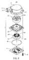
- FIG. 2shows an exploded perspective view of a water-cooling heat dissipation device according to the present invention
- FIG. 3shows another exploded perspective view of the water-cooling heat dissipation device
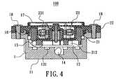
- FIG. 4shows a cross sectional view of the water-cooling heat dissipation device
- FIG. 5shows an assembly of the water-cooling heat dissipation device and a mounting plate
- FIG. 6shows the water-cooling heat dissipation device of the present invention mounted in a computer associated with a cooling device
- FIG. 7shows a cross sectional view of the water-cooling heat dissipation device mounted on a CPU
- FIG. 8shows another preferred embodiment of the water-cooling heat dissipation device according to the present invention.
- FIG. 9shows still another preferred embodiment of the water-cooling heat dissipation device according to the present invention.
- a water-cooling heat dissipation device 100 of the present inventioncan be used for a CPU, such as shown in FIG. 7 .
- the water-cooling heat dissipation device 100includes a housing 1 and a water circulator 2 .
- a bottom surface 11 of the housing 1 for contact with the CPU 200is made of heat conductive material such as copper or aluminum.
- the whole housing 1can be made of heat conductive material such as metal.
- the housing 1includes a recess 12 .
- a plurality of apertures 131are formed on the bottom of the recess 12 as a water passage 13 .
- the water circulator 2includes a rotor component 21 , a retainer component 22 and a stator component 23 .
- the rotor component 21includes a magnetic pole 211 and an impeller 212 .
- the stator component 23includes a circuit board 231 , a coil 232 and a core 233 .
- the housing 1includes a water inlet 14 and water outlet 15 both connected to the recess 12 .
- a sealing O-ring 16 and a lid 17cover on the top of the housing 1 to fit the water circulator 2 inside the housing 1 .
- the rotor component 21 and the stator component 23are respectively disposed on the retainer component 22 to combine as the water circulator 2 .
- the water circulator 2is then installed in the recess 12 to have the impeller 212 located corresponding to the water passage 13 .
- the O-ring 16 and the lid 17are put on the top of the housing 1 and a fastening element 18 is used to secure the lid 17 with the housing 1 , the assembly of the water-cooling heat dissipation device 100 of the present invention is completed.
- a mounting plate 201is provided to fix on the water-cooling heat dissipation device 100 by a bolt 202 .
- the bottom surface 11 of the housing 1can contact with the CPU 200 .
- two pipes 3are provided to connect the water inlet 14 and the water outlet 15 , respectively.
- the other ends of two pipes 3are connected to a cooler 4 .
- the cooler 4includes a main body 41 , a water inlet tube 42 and a water outlet tube 43 .
- One pipe 3is connected between the water inlet 14 and the water outlet tube 43 .
- the other pipe 3is connected between the water outlet 15 and the water inlet tube 42 .
- the main body 41includes a plurality of stacked fins 44 . Therefore, the warmer water flows into the water inlet tube 42 can be cooled down via the heat exchange of the fins 44 to provide cooler water flowing out from the water outlet tube 42 to the water-cooling heat dissipation device 100 .
- a fan 45can be mounted to the main body 41 at the side of the stacked fins 44 to speed heat exchange of the fins 44 .
- heat generated from the CPU 200is conducted to the water-cooling heat dissipation device 100 via the housing 1 .
- the cooler water input from the water outlet tube 42flows into the water inlet 14 through the pipe 3 and further flows into the recess 12 through the water passage 13 .
- the cooler wateris heated by the CPU 200 to take away the heat of the CPU 200 .
- the heated waterthen flows out of the water-cooling heat dissipation device 100 from the water outlet 15 to the water inlet tube 42 through the pipe 3 .
- the warmer water heated by the CPU 200can be cooled down through the stacked fins 44 to supply cooler water again for the water-cooling heat dissipation device 100 .
- the water passage 13 formed in the recess 12includes a plurality of protruded columns 132 .
- the water passage 13includes a plurality of vortex slots 133 .
- the water-cooling heat dissipation device 100utilizes the housing 1 directly attached to the CPU 200 to conduct heat.
- the water circulator 2can be fully contained inside the housing 1 .
- the compact structure of the water-cooling heat dissipation device 100reduces cost, weight and volume to provide functions of water storage, water circulation and heat exchange all together. Meanwhile, because the location of the impeller 212 is right above the water passage 13 , during the rotation of the impeller 212 , the water flowing rate can be increased to enhance the heat exchanging efficiency.
Landscapes
- Engineering & Computer Science (AREA)
- Theoretical Computer Science (AREA)
- Human Computer Interaction (AREA)
- Physics & Mathematics (AREA)
- General Engineering & Computer Science (AREA)
- General Physics & Mathematics (AREA)
- Cooling Or The Like Of Semiconductors Or Solid State Devices (AREA)
- Cooling Or The Like Of Electrical Apparatus (AREA)
Abstract
Description
Claims (10)
Priority Applications (1)
| Application Number | Priority Date | Filing Date | Title |
|---|---|---|---|
| US11/195,785US7249625B2 (en) | 2005-08-03 | 2005-08-03 | Water-cooling heat dissipation device |
Applications Claiming Priority (1)
| Application Number | Priority Date | Filing Date | Title |
|---|---|---|---|
| US11/195,785US7249625B2 (en) | 2005-08-03 | 2005-08-03 | Water-cooling heat dissipation device |
Publications (2)
| Publication Number | Publication Date |
|---|---|
| US20070029069A1 US20070029069A1 (en) | 2007-02-08 |
| US7249625B2true US7249625B2 (en) | 2007-07-31 |
Family
ID=37716603
Family Applications (1)
| Application Number | Title | Priority Date | Filing Date |
|---|---|---|---|
| US11/195,785Active2025-10-29US7249625B2 (en) | 2005-08-03 | 2005-08-03 | Water-cooling heat dissipation device |
Country Status (1)
| Country | Link |
|---|---|
| US (1) | US7249625B2 (en) |
Cited By (26)
| Publication number | Priority date | Publication date | Assignee | Title |
|---|---|---|---|---|
| US20070034359A1 (en)* | 2005-08-10 | 2007-02-15 | Tay-Jian Liu | Integrated liquid cooling system for electronic components |
| US20080053641A1 (en)* | 2006-08-31 | 2008-03-06 | Foxconn Technology Co., Ltd. | Miniature liquid cooling device having an integral pump |
| US20080075611A1 (en)* | 2006-09-21 | 2008-03-27 | Foxconn Technology Co., Ltd. | Miniature liquid cooling device having an integral pump therein |
| US20080225488A1 (en)* | 2007-03-16 | 2008-09-18 | International Business Machines Corporation | Pump structures integral to a fluid filled heat transfer apparatus |
| US20090090489A1 (en)* | 2007-10-05 | 2009-04-09 | Asia Vital Components Co., Ltd. | Water-cooling heat-dissipating module of electronic apparatus |
| US20090116196A1 (en)* | 2007-11-01 | 2009-05-07 | Kuei-Fung Chiang | Water cooled heat dissipation module for electronic device |
| US20110186270A1 (en)* | 2010-02-01 | 2011-08-04 | Suna Display Co. | Heat transfer device with anisotropic heat dissipating and absorption structures |
| US20140216695A1 (en)* | 2013-02-05 | 2014-08-07 | Bor-bin Tsai | Water-cooling module |
| US20160234968A1 (en)* | 2015-02-10 | 2016-08-11 | Dynatron Corporation | Liquid-Cooled Heat Sink for Electronic Devices |
| US20170034950A1 (en)* | 2015-07-31 | 2017-02-02 | Cooler Master Co., Ltd. | Liquid supply device and liquid cooling system |
| US9615482B2 (en) | 2009-12-11 | 2017-04-04 | General Electric Company | Shaped heat sinks to optimize flow |
| US20170115708A1 (en)* | 2015-07-24 | 2017-04-27 | Niko Tivadar | Computer liquid cooling system and method of use |
| US20170235350A1 (en)* | 2016-02-15 | 2017-08-17 | Cooler Master Technology Inc. | Cooling apparatus |
| US20180023594A1 (en)* | 2016-07-25 | 2018-01-25 | Dongguan Zhenpin Hardware Cooling Technology Co. L td | Water Pump Cooler for CPU |
| US20180109061A1 (en)* | 2016-10-17 | 2018-04-19 | Waymo Llc | Thermal Rotary Link |
| US10274264B2 (en) | 2009-04-09 | 2019-04-30 | General Electric Company | Method and apparatus for improved cooling of a heat sink using a synthetic jet |
| US10410955B2 (en) | 2015-01-28 | 2019-09-10 | Cooler Master Co., Ltd. | Liquid cooling heat sink structure and cooling circulation system thereof |
| US10455732B2 (en)* | 2016-05-20 | 2019-10-22 | Kuan Ding Industrial Co., Ltd. | Liquid-cooled heat dissipation apparatus |
| US10509446B2 (en) | 2015-12-30 | 2019-12-17 | Cooler Master Co., Ltd. | Cooling apparatus for electronic components |
| US10739084B2 (en) | 2015-01-28 | 2020-08-11 | Cooler Master Co., Ltd. | Liquid cooling heat sink structure and cooling circulation system thereof |
| US10975876B2 (en) | 2019-04-19 | 2021-04-13 | Cooler Master Co., Ltd. | Cooling device |
| US11297735B2 (en)* | 2019-04-23 | 2022-04-05 | In Win Development Inc. | Heat exchange device and liquid cooling system having the same |
| US11460035B2 (en) | 2019-10-07 | 2022-10-04 | Cooler Master Co., Ltd. | Light emitting fan device and non-light emitting fan device |
| US11460036B2 (en) | 2019-10-07 | 2022-10-04 | Cooler Master Co., Ltd. | Light emitting fan device and non-light emitting fan device |
| US12099385B2 (en) | 2016-02-15 | 2024-09-24 | Cooler Master Co., Ltd. | Cooling apparatus |
| US12158786B2 (en) | 2016-02-15 | 2024-12-03 | Cooler Master Co., Ltd. | Cooling apparatus |
Families Citing this family (30)
| Publication number | Priority date | Publication date | Assignee | Title |
|---|---|---|---|---|
| US7325591B2 (en)* | 2005-02-18 | 2008-02-05 | Cooler Master Co., Ltd. | Liquid-cooling heat dissipation apparatus |
| US20070272397A1 (en)* | 2006-05-23 | 2007-11-29 | Ilya Reyzin | Compact liquid cooling unit for high end servers |
| US7467657B2 (en)* | 2006-06-07 | 2008-12-23 | Delphi Technologies, Inc. | Compact modular CPU cooling unit |
| US7729118B2 (en)* | 2006-11-03 | 2010-06-01 | Fu Zhun Precision Industry (Shen Zhen) Co., Ltd. | Miniature liquid cooling device having an integral pump |
| US8746330B2 (en) | 2007-08-09 | 2014-06-10 | Coolit Systems Inc. | Fluid heat exchanger configured to provide a split flow |
| US9453691B2 (en) | 2007-08-09 | 2016-09-27 | Coolit Systems, Inc. | Fluid heat exchange systems |
| US20090044929A1 (en)* | 2007-08-15 | 2009-02-19 | Xigmatek Co., Ltd | Liquid cooling module |
| TW200910068A (en)* | 2007-08-20 | 2009-03-01 | Asustek Comp Inc | Heat dissipation apparatus |
| US20090205809A1 (en)* | 2008-02-19 | 2009-08-20 | Man Zai Industrial Co., Ltd. | Liquid cooling device |
| US9478479B2 (en)* | 2010-10-26 | 2016-10-25 | General Electric Company | Thermal management system and method |
| US10365667B2 (en) | 2011-08-11 | 2019-07-30 | Coolit Systems, Inc. | Flow-path controllers and related systems |
| US12366870B2 (en) | 2013-03-15 | 2025-07-22 | Coolit Systems, Inc. | Flow-path controllers and related systems |
| US10364809B2 (en) | 2013-03-15 | 2019-07-30 | Coolit Systems, Inc. | Sensors, multiplexed communication techniques, and related systems |
| US10415597B2 (en) | 2014-10-27 | 2019-09-17 | Coolit Systems, Inc. | Fluid heat exchange systems |
| US20160377356A1 (en)* | 2015-06-25 | 2016-12-29 | Asia Vital Components Co., Ltd. | Flexible and transformable water-cooling device |
| CN105351900A (en)* | 2015-11-09 | 2016-02-24 | 适新科技(苏州)有限公司 | Cooling mechanism of LED curing device |
| WO2017141215A1 (en)* | 2016-02-18 | 2017-08-24 | Eric Matte | High efficiency heat dissipation methods and systems for electronic circuits and systems |
| TWM534958U (en)* | 2016-09-30 | 2017-01-01 | 微星科技股份有限公司 | Liquid cooling heat dissipating module |
| US11452243B2 (en) | 2017-10-12 | 2022-09-20 | Coolit Systems, Inc. | Cooling system, controllers and methods |
| US10681841B2 (en)* | 2018-08-08 | 2020-06-09 | Evga Corporation | Water-cooling heat dissipation device suitable for computer |
| CN109308109B (en)* | 2018-12-08 | 2025-03-21 | 武汉易知鸟科技有限公司 | A water cooling radiator and method for computer graphics card |
| US11662037B2 (en) | 2019-01-18 | 2023-05-30 | Coolit Systems, Inc. | Fluid flow control valve for fluid flow systems, and methods |
| CN109696008B (en)* | 2019-01-31 | 2023-09-26 | 深圳市研派科技有限公司 | Fluid cooling device |
| US11473860B2 (en) | 2019-04-25 | 2022-10-18 | Coolit Systems, Inc. | Cooling module with leak detector and related systems |
| CN111684390A (en)* | 2019-05-05 | 2020-09-18 | 深圳市大疆创新科技有限公司 | Cooling structure, computer system and movable platform |
| US10939592B2 (en)* | 2019-06-14 | 2021-03-02 | Intel Corporation | Liquid cooling system with sub atmospheric pressure coolant |
| WO2021229365A1 (en) | 2020-05-11 | 2021-11-18 | Coolit Systems, Inc. | Liquid pumping units, and related systems and methods |
| US11725886B2 (en) | 2021-05-20 | 2023-08-15 | Coolit Systems, Inc. | Modular fluid heat exchange systems |
| US12200914B2 (en) | 2022-01-24 | 2025-01-14 | Coolit Systems, Inc. | Smart components, systems and methods for transferring heat |
| CN115615074B (en)* | 2022-10-31 | 2025-04-25 | 苏州贝爱特自动化科技有限公司 | A wafer curing water cooling platform |
Citations (9)
| Publication number | Priority date | Publication date | Assignee | Title |
|---|---|---|---|---|
| US5729995A (en)* | 1995-03-20 | 1998-03-24 | Calsonic Corporation | Electronic component cooling unit |
| US6019165A (en)* | 1998-05-18 | 2000-02-01 | Batchelder; John Samuel | Heat exchange apparatus |
| US6580610B2 (en)* | 2000-07-31 | 2003-06-17 | Hewlett-Packard Development Company, L.P. | Integrated EMI containment and spray cooling module utilizing a magnetically coupled pump |
| US20040173342A1 (en)* | 2001-05-11 | 2004-09-09 | Hajime Sugito | Cooling device boiling and condensing refrigerant |
| US20040240179A1 (en)* | 2003-05-26 | 2004-12-02 | Shinya Koga | Cooling device and centrifugal pump to be used in the same device |
| US20060144569A1 (en)* | 2004-12-31 | 2006-07-06 | Crocker Michael T | Systems for improved heat exchanger |
| US20060157230A1 (en)* | 2003-05-30 | 2006-07-20 | Shoji Kawahara | Cooling device |
| US20060185829A1 (en)* | 2005-02-18 | 2006-08-24 | Cooler Master Co., Ltd. | Liquid-cooling heat dissipation apparatus |
| US20060191669A1 (en)* | 2005-02-25 | 2006-08-31 | Delta Electronics, Inc. | Liquid-cooled heat dissipation module |
- 2005
- 2005-08-03USUS11/195,785patent/US7249625B2/enactiveActive
Patent Citations (9)
| Publication number | Priority date | Publication date | Assignee | Title |
|---|---|---|---|---|
| US5729995A (en)* | 1995-03-20 | 1998-03-24 | Calsonic Corporation | Electronic component cooling unit |
| US6019165A (en)* | 1998-05-18 | 2000-02-01 | Batchelder; John Samuel | Heat exchange apparatus |
| US6580610B2 (en)* | 2000-07-31 | 2003-06-17 | Hewlett-Packard Development Company, L.P. | Integrated EMI containment and spray cooling module utilizing a magnetically coupled pump |
| US20040173342A1 (en)* | 2001-05-11 | 2004-09-09 | Hajime Sugito | Cooling device boiling and condensing refrigerant |
| US20040240179A1 (en)* | 2003-05-26 | 2004-12-02 | Shinya Koga | Cooling device and centrifugal pump to be used in the same device |
| US20060157230A1 (en)* | 2003-05-30 | 2006-07-20 | Shoji Kawahara | Cooling device |
| US20060144569A1 (en)* | 2004-12-31 | 2006-07-06 | Crocker Michael T | Systems for improved heat exchanger |
| US20060185829A1 (en)* | 2005-02-18 | 2006-08-24 | Cooler Master Co., Ltd. | Liquid-cooling heat dissipation apparatus |
| US20060191669A1 (en)* | 2005-02-25 | 2006-08-31 | Delta Electronics, Inc. | Liquid-cooled heat dissipation module |
Cited By (45)
| Publication number | Priority date | Publication date | Assignee | Title |
|---|---|---|---|---|
| US20070034359A1 (en)* | 2005-08-10 | 2007-02-15 | Tay-Jian Liu | Integrated liquid cooling system for electronic components |
| US7537048B2 (en)* | 2005-08-10 | 2009-05-26 | Foxconn Technology Co., Ltd. | Integrated liquid cooling system for electronic components |
| US7694721B2 (en)* | 2006-08-31 | 2010-04-13 | Fu Zhun Precision Industry (Shen Zhen) Co., Ltd. | Miniature liquid cooling device having an integral pump |
| US20080053641A1 (en)* | 2006-08-31 | 2008-03-06 | Foxconn Technology Co., Ltd. | Miniature liquid cooling device having an integral pump |
| US20080075611A1 (en)* | 2006-09-21 | 2008-03-27 | Foxconn Technology Co., Ltd. | Miniature liquid cooling device having an integral pump therein |
| US7753662B2 (en)* | 2006-09-21 | 2010-07-13 | Fu Zhun Precision Industry (Shen Zhen) Co., Ltd. | Miniature liquid cooling device having an integral pump therein |
| US20080225488A1 (en)* | 2007-03-16 | 2008-09-18 | International Business Machines Corporation | Pump structures integral to a fluid filled heat transfer apparatus |
| US7667969B2 (en)* | 2007-03-16 | 2010-02-23 | International Business Machines Corporation | Pump structures integral to a fluid filled heat transfer apparatus |
| US20090090489A1 (en)* | 2007-10-05 | 2009-04-09 | Asia Vital Components Co., Ltd. | Water-cooling heat-dissipating module of electronic apparatus |
| US7688589B2 (en)* | 2007-11-01 | 2010-03-30 | Asia Vital Components Co., Ltd. | Water cooled heat dissipation module for electronic device |
| US20090116196A1 (en)* | 2007-11-01 | 2009-05-07 | Kuei-Fung Chiang | Water cooled heat dissipation module for electronic device |
| US9854704B2 (en) | 2009-04-09 | 2017-12-26 | General Electric Company | Shaped heat sinks to optimize flow |
| US10274263B2 (en) | 2009-04-09 | 2019-04-30 | General Electric Company | Method and apparatus for improved cooling of a heat sink using a synthetic jet |
| US10274264B2 (en) | 2009-04-09 | 2019-04-30 | General Electric Company | Method and apparatus for improved cooling of a heat sink using a synthetic jet |
| US9615482B2 (en) | 2009-12-11 | 2017-04-04 | General Electric Company | Shaped heat sinks to optimize flow |
| US20110186270A1 (en)* | 2010-02-01 | 2011-08-04 | Suna Display Co. | Heat transfer device with anisotropic heat dissipating and absorption structures |
| US20140216695A1 (en)* | 2013-02-05 | 2014-08-07 | Bor-bin Tsai | Water-cooling module |
| US9689627B2 (en)* | 2013-02-05 | 2017-06-27 | Asia Vital Components Co., Ltd. | Water-cooling device with waterproof stator and rotor pumping unit |
| US10410955B2 (en) | 2015-01-28 | 2019-09-10 | Cooler Master Co., Ltd. | Liquid cooling heat sink structure and cooling circulation system thereof |
| US10739084B2 (en) | 2015-01-28 | 2020-08-11 | Cooler Master Co., Ltd. | Liquid cooling heat sink structure and cooling circulation system thereof |
| US9818671B2 (en)* | 2015-02-10 | 2017-11-14 | Dynatron Corporation | Liquid-cooled heat sink for electronic devices |
| US20160234968A1 (en)* | 2015-02-10 | 2016-08-11 | Dynatron Corporation | Liquid-Cooled Heat Sink for Electronic Devices |
| US20170115708A1 (en)* | 2015-07-24 | 2017-04-27 | Niko Tivadar | Computer liquid cooling system and method of use |
| US11337334B2 (en)* | 2015-07-31 | 2022-05-17 | Cooler Master Co., Ltd. | Liquid supply device and liquid cooling system |
| US20170034950A1 (en)* | 2015-07-31 | 2017-02-02 | Cooler Master Co., Ltd. | Liquid supply device and liquid cooling system |
| US11061450B2 (en) | 2015-12-30 | 2021-07-13 | Cooler Master Development Corporation | Cooling apparatus for electronic components |
| US10509446B2 (en) | 2015-12-30 | 2019-12-17 | Cooler Master Co., Ltd. | Cooling apparatus for electronic components |
| US20170235350A1 (en)* | 2016-02-15 | 2017-08-17 | Cooler Master Technology Inc. | Cooling apparatus |
| US10409341B2 (en)* | 2016-02-15 | 2019-09-10 | Cooler Master Co., Ltd. | Cooling apparatus |
| US12158786B2 (en) | 2016-02-15 | 2024-12-03 | Cooler Master Co., Ltd. | Cooling apparatus |
| US12099385B2 (en) | 2016-02-15 | 2024-09-24 | Cooler Master Co., Ltd. | Cooling apparatus |
| US11474574B2 (en) | 2016-02-15 | 2022-10-18 | Cooler Master Development Corporation | Cooling apparatus |
| US11334126B2 (en) | 2016-02-15 | 2022-05-17 | Cooler Master Development Corporation | Cooling apparatus |
| US11320874B2 (en) | 2016-02-15 | 2022-05-03 | Cooler Master Development Corporation | Cooling apparatus |
| US10455732B2 (en)* | 2016-05-20 | 2019-10-22 | Kuan Ding Industrial Co., Ltd. | Liquid-cooled heat dissipation apparatus |
| US10883518B2 (en)* | 2016-07-25 | 2021-01-05 | Dongguan Zhenpin Hardware Cooling Technology Co. Ltd | Water pump cooler for CPU |
| US20180023594A1 (en)* | 2016-07-25 | 2018-01-25 | Dongguan Zhenpin Hardware Cooling Technology Co. L td | Water Pump Cooler for CPU |
| US20180109061A1 (en)* | 2016-10-17 | 2018-04-19 | Waymo Llc | Thermal Rotary Link |
| CN112928585A (en)* | 2016-10-17 | 2021-06-08 | 伟摩有限责任公司 | Thermal rotary connection device, thermal rotary connection system and thermal rotary connection method |
| US11569629B2 (en)* | 2016-10-17 | 2023-01-31 | Waymo Llc | Thermal rotary link |
| US10749308B2 (en)* | 2016-10-17 | 2020-08-18 | Waymo Llc | Thermal rotary link |
| US10975876B2 (en) | 2019-04-19 | 2021-04-13 | Cooler Master Co., Ltd. | Cooling device |
| US11297735B2 (en)* | 2019-04-23 | 2022-04-05 | In Win Development Inc. | Heat exchange device and liquid cooling system having the same |
| US11460035B2 (en) | 2019-10-07 | 2022-10-04 | Cooler Master Co., Ltd. | Light emitting fan device and non-light emitting fan device |
| US11460036B2 (en) | 2019-10-07 | 2022-10-04 | Cooler Master Co., Ltd. | Light emitting fan device and non-light emitting fan device |
Also Published As
| Publication number | Publication date |
|---|---|
| US20070029069A1 (en) | 2007-02-08 |
Similar Documents
| Publication | Publication Date | Title |
|---|---|---|
| US7249625B2 (en) | Water-cooling heat dissipation device | |
| US7418996B2 (en) | Integrated liquid cooling system for electronic components | |
| US7472743B2 (en) | Liquid cooling system suitable for removing heat from electronic components | |
| US6900990B2 (en) | Electronic apparatus provided with liquid cooling type cooling unit cooling heat generating component | |
| US6234240B1 (en) | Fanless cooling system for computer | |
| US6687126B2 (en) | Cooling plate arrangement for electronic components | |
| US7319587B2 (en) | Electronic apparatus having pump unit | |
| US7537048B2 (en) | Integrated liquid cooling system for electronic components | |
| US7715194B2 (en) | Methodology of cooling multiple heat sources in a personal computer through the use of multiple fluid-based heat exchanging loops coupled via modular bus-type heat exchangers | |
| US20120175094A1 (en) | Liquid Cooling System Cold Plate Assembly | |
| US20040042171A1 (en) | Electronic apparatus having display unit containing radiator radiating heat of heat generating component | |
| CN100394352C (en) | cooling jacket | |
| US20040080912A1 (en) | Evaporator with air cooling backup | |
| US20240419226A1 (en) | Cooling apparatus | |
| US11137175B2 (en) | Composite water-cooling radiator structure | |
| JP7346736B2 (en) | heat sink for liquid cooling | |
| US20070110592A1 (en) | Integrated liquid cooling system | |
| US20070107441A1 (en) | Heat-dissipating unit and related liquid cooling module | |
| JP2006207881A (en) | COOLING DEVICE AND ELECTRONIC DEVICE HAVING THE SAME | |
| US10874034B1 (en) | Pump driven liquid cooling module with tower fins | |
| US10921067B2 (en) | Water-cooling radiator structure with internal partition member | |
| US20050183848A1 (en) | Coolant tray of liquid based cooling device | |
| US20070289719A1 (en) | Cooling apparatus and system thereof | |
| JP2004071882A (en) | Electronics | |
| US20050024824A1 (en) | Arrangement for cooling heat-generating computer components |
Legal Events
| Date | Code | Title | Description |
|---|---|---|---|
| AS | Assignment | Owner name:COOLER MASTER CO., LTD., TAIWAN Free format text:ASSIGNMENT OF ASSIGNORS INTEREST;ASSIGNOR:DUAN, QIANG-FEI;REEL/FRAME:016828/0731 Effective date:20040616 | |
| FEPP | Fee payment procedure | Free format text:ENTITY STATUS SET TO UNDISCOUNTED (ORIGINAL EVENT CODE: BIG.); ENTITY STATUS OF PATENT OWNER: LARGE ENTITY | |
| STCF | Information on status: patent grant | Free format text:PATENTED CASE | |
| FPAY | Fee payment | Year of fee payment:4 | |
| FEPP | Fee payment procedure | Free format text:PAYOR NUMBER ASSIGNED (ORIGINAL EVENT CODE: ASPN); ENTITY STATUS OF PATENT OWNER: LARGE ENTITY | |
| AS | Assignment | Owner name:COOLER MASTER CO., LTD., TAIWAN Free format text:CORRECTIVE ASSIGNMENT TO CORRECT THE CONVEYANCE EXECUTIVE DATE PREVIOUSLY RECORDED ON REEL 016828 FRAME 0731. ASSIGNOR(S) HEREBY CONFIRMS THE DATE 06/16/2004 IS INCORRECT AND SHOULD BE 06/16/2005;ASSIGNOR:DUAN, QIANG-FEI;REEL/FRAME:027248/0420 Effective date:20050616 | |
| AS | Assignment | Owner name:CHEMTRON RESEARCH LLC, DELAWARE Free format text:ASSIGNMENT OF ASSIGNORS INTEREST;ASSIGNOR:COOLER MASTER CO., LTD.;REEL/FRAME:027567/0332 Effective date:20111116 | |
| FPAY | Fee payment | Year of fee payment:8 | |
| MAFP | Maintenance fee payment | Free format text:PAYMENT OF MAINTENANCE FEE, 12TH YEAR, LARGE ENTITY (ORIGINAL EVENT CODE: M1553); ENTITY STATUS OF PATENT OWNER: LARGE ENTITY Year of fee payment:12 |