US7248892B2 - Electrical devices - Google Patents
Electrical devicesDownload PDFInfo
- Publication number
- US7248892B2 US7248892B2US10/477,733US47773304AUS7248892B2US 7248892 B2US7248892 B2US 7248892B2US 47773304 AUS47773304 AUS 47773304AUS 7248892 B2US7248892 B2US 7248892B2
- Authority
- US
- United States
- Prior art keywords
- data
- storage device
- data storage
- radio frequency
- operable
- Prior art date
- Legal status (The legal status is an assumption and is not a legal conclusion. Google has not performed a legal analysis and makes no representation as to the accuracy of the status listed.)
- Expired - Lifetime
Links
Images


Classifications
- H—ELECTRICITY
- H04—ELECTRIC COMMUNICATION TECHNIQUE
- H04M—TELEPHONIC COMMUNICATION
- H04M1/00—Substation equipment, e.g. for use by subscribers
- H04M1/02—Constructional features of telephone sets
- H04M1/0202—Portable telephone sets, e.g. cordless phones, mobile phones or bar type handsets
- H04M1/0254—Portable telephone sets, e.g. cordless phones, mobile phones or bar type handsets comprising one or a plurality of mechanically detachable modules
- H04M1/0256—Portable telephone sets, e.g. cordless phones, mobile phones or bar type handsets comprising one or a plurality of mechanically detachable modules wherein the modules are operable in the detached state, e.g. one module for the user interface and one module for the transceiver
- B—PERFORMING OPERATIONS; TRANSPORTING
- B23—MACHINE TOOLS; METAL-WORKING NOT OTHERWISE PROVIDED FOR
- B23Q—DETAILS, COMPONENTS, OR ACCESSORIES FOR MACHINE TOOLS, e.g. ARRANGEMENTS FOR COPYING OR CONTROLLING; MACHINE TOOLS IN GENERAL CHARACTERISED BY THE CONSTRUCTION OF PARTICULAR DETAILS OR COMPONENTS; COMBINATIONS OR ASSOCIATIONS OF METAL-WORKING MACHINES, NOT DIRECTED TO A PARTICULAR RESULT
- B23Q1/00—Members which are comprised in the general build-up of a form of machine, particularly relatively large fixed members
- B23Q1/0009—Energy-transferring means or control lines for movable machine parts; Control panels or boxes; Control parts
- H—ELECTRICITY
- H04—ELECTRIC COMMUNICATION TECHNIQUE
- H04M—TELEPHONIC COMMUNICATION
- H04M1/00—Substation equipment, e.g. for use by subscribers
- H04M1/02—Constructional features of telephone sets
- H04M1/0202—Portable telephone sets, e.g. cordless phones, mobile phones or bar type handsets
- H04M1/0279—Improving the user comfort or ergonomics
- H04M1/0283—Improving the user comfort or ergonomics for providing a decorative aspect, e.g. customization of casings, exchangeable faceplate
- H—ELECTRICITY
- H04—ELECTRIC COMMUNICATION TECHNIQUE
- H04M—TELEPHONIC COMMUNICATION
- H04M1/00—Substation equipment, e.g. for use by subscribers
- H04M1/72—Mobile telephones; Cordless telephones, i.e. devices for establishing wireless links to base stations without route selection
- H04M1/724—User interfaces specially adapted for cordless or mobile telephones
- H04M1/72448—User interfaces specially adapted for cordless or mobile telephones with means for adapting the functionality of the device according to specific conditions
- H04M1/7246—User interfaces specially adapted for cordless or mobile telephones with means for adapting the functionality of the device according to specific conditions by connection of exchangeable housing parts
- H—ELECTRICITY
- H04—ELECTRIC COMMUNICATION TECHNIQUE
- H04M—TELEPHONIC COMMUNICATION
- H04M1/00—Substation equipment, e.g. for use by subscribers
- H04M1/72—Mobile telephones; Cordless telephones, i.e. devices for establishing wireless links to base stations without route selection
- H04M1/724—User interfaces specially adapted for cordless or mobile telephones
- H04M1/72403—User interfaces specially adapted for cordless or mobile telephones with means for local support of applications that increase the functionality
- H04M1/72406—User interfaces specially adapted for cordless or mobile telephones with means for local support of applications that increase the functionality by software upgrading or downloading
- H—ELECTRICITY
- H04—ELECTRIC COMMUNICATION TECHNIQUE
- H04M—TELEPHONIC COMMUNICATION
- H04M1/00—Substation equipment, e.g. for use by subscribers
- H04M1/72—Mobile telephones; Cordless telephones, i.e. devices for establishing wireless links to base stations without route selection
- H04M1/724—User interfaces specially adapted for cordless or mobile telephones
- H04M1/72403—User interfaces specially adapted for cordless or mobile telephones with means for local support of applications that increase the functionality
- H04M1/72427—User interfaces specially adapted for cordless or mobile telephones with means for local support of applications that increase the functionality for supporting games or graphical animations
- H—ELECTRICITY
- H04—ELECTRIC COMMUNICATION TECHNIQUE
- H04M—TELEPHONIC COMMUNICATION
- H04M1/00—Substation equipment, e.g. for use by subscribers
- H04M1/72—Mobile telephones; Cordless telephones, i.e. devices for establishing wireless links to base stations without route selection
- H04M1/724—User interfaces specially adapted for cordless or mobile telephones
- H04M1/72403—User interfaces specially adapted for cordless or mobile telephones with means for local support of applications that increase the functionality
- H04M1/72445—User interfaces specially adapted for cordless or mobile telephones with means for local support of applications that increase the functionality for supporting Internet browser applications
- H—ELECTRICITY
- H04—ELECTRIC COMMUNICATION TECHNIQUE
- H04M—TELEPHONIC COMMUNICATION
- H04M2250/00—Details of telephonic subscriber devices
- H04M2250/22—Details of telephonic subscriber devices including a touch pad, a touch sensor or a touch detector
Definitions
- This inventionrelates to electrical devices having attachable components especially portable communications devices such as telephones arranged to operate using a mobile telecommunications network and to attachable components for such portable communications devices.
- Telephones that operate using a mobile telecommunications networkare variously known as mobile telephones, cellular telephones and cellphones.
- mobile telephoneFor simplicity, the term “mobile telephone” will be used hereinafter.
- the present inventionprovides a mobile telephone housing portion such as a fascia that, when fitted to a mobile telephone, affects the functionality and/or operating characteristics of the mobile telephone.
- the mobile telephone fasciamay provide the mobile telephone with additional, different or modified functionality or operating characteristics. Different mobile telephone fascias may affect a mobile telephone differently. For example, access to functions or operating characteristics of the mobile telephone may be limited or controlled by the particular fascia fitted to the mobile telephone.
- the present inventionprovides a fascia for a portable communications device such as a mobile telephone, the fascia having a passive data storage device carrying control data (which may be software data and/or information data) that is supplied to a main body of the mobile telephone when the fascia is attached to and/or detached from the main body and which affects the functioning and/or operating characteristics of the mobile telephone.
- control datawhich may be software data and/or information data
- bypassive data storage devicemeans a device that is not self-powered but that derives power from the main body when the fascia is attached to the main body.
- the present inventionprovides a mobile telephone having a main body and a fascia arranged to fit on the main body, the fascia carrying a passive detectable element and the main body having detection means for detecting the presence of the passive detectable element and control means for controlling the functionality or operating characteristics of the mobile telephone in accordance with control data, wherein the control data accessed by the control means is affected by the presence of a passive detachable element or the presence of a particular passive detectable element.
- the term passive detachable elementmeans an element that is not self-powered and that, if it requires a power supply, derives it from the main body when the fascia is attached to the main body.
- control datamay comprise data for at least one of: graphics; mobile telephone services; subscription services; network services; services; promotions; and advertisement; fascia identification data; games software for games that may be played on the mobile telephone including a new game or modifications for such games software already installed on the mobile telephone; and data for enabling a user to access any one or more of the above types of data using their mobile telephone, for example an access code to enable access to control data already stored by the mobile telephone or data such as a telephone number, Internet address or WAP address from which control data can be accessed, or the user's mobile network provider or another third party service provider.
- the present inventionprovides a fascia for a telephone wherein the fascia carries a data storage device carrying identification data that, when the fascia is attached to a main body of the telephone, enables the telephone to determine whether or not the user has access to additional or optional functions of the telephone, for example access to additional optional ringing tones stored by the main body and/or access to games programs or games modifications stored by the main body.
- the data storage devicemay be a writable data storage device into which, for example, historical data such as use data may be written. Such data may be accumulated by the main body of the mobile telephone which may control the writing of this data into the data storage device. Data may also be written into a SIM card memory.
- the mobile telephone fasciais provided with apertures through which key pads of a user interface of the telephone project.
- the mobile telephone fasciacarries a user interface.
- the user interfacemay be at least one of a keyboard, touch screen and so on.
- Different fasciasmay carry different types of user interfaces.
- Datamay be communicated by modulation by the data storage device of a carrier signal supplied by the electronic device or electrical appliance and from which the data storage device derives its power.
- the deviceis an electrical device other than a portable or mobile communications device and the attachable component is at least one of a housing portion or a tool or is, rather than being attachable, arranged to be brought into close proximity with a reader unit carried by the electrical device.
- the present inventionalso provides a tool having such a passive detectable element.
- the present inventionalso provides a tool that is attachable to a main body of an electrical appliance, the tool carrying a passive data storage device such that, when the tool is attached to the main body of the electrical appliance, control data is downloaded from the passive data storage device to the main body to affect the control by the electrical appliance of the operation of the tool.
- control datamay affect the speed or duration for which the tool is vibrated, rotated oscillated or reciprocated.
- the control datamay be identification data that enables the electrical appliance to determine from its own memory the required drive characteristics (for example speed and duration) for that particular tool or may be instruction data that instructs the electrical appliance how to control the particular tool.
- the electrical appliancemay be: a personal care electrical appliance such as dental hygiene device such as an electric toothbrush, a beauty care device such as a skin care device or a hair dryer; a domestic appliance such as a vacuum cleaner, food processor; or a power tool.
- dental hygiene devicesuch as an electric toothbrush
- beauty care devicesuch as a skin care device or a hair dryer
- domestic appliancesuch as a vacuum cleaner, food processor
- FIG. 1shows a diagrammatic perspective view of a mobile telephone with a removable fascia embodying the invention separated from a main body of the mobile telephone;
- FIG. 2shows a functional block diagram of functional components of a mobile telephone embodying the invention, including a reader unit for enabling detection of a replacement fascia;
- FIG. 3shows a functional block diagram of an embodiment of the reader unit shown in FIG. 2 ;
- FIG. 4shows a functional block diagram of an example of a passive data storage device
- FIG. 5shows a more detailed functional block diagram of an embodiment of the reader unit
- FIG. 6shows a more detailed functional block diagram of one example of a passive data storage device
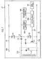
- FIG. 7shows a functional block diagram of another example of a passive data storage device
- FIG. 8shows a functional block diagram of another example of a mobile telephone embodying the present invention.
- FIG. 9shows a functional block diagram of an example of a passive data storage device for use as a detectable control device shown in FIG. 8 ;
- FIGS. 10 to 12are very diagrammatic views of examples of user input devices
- FIGS. 13 to 15show block diagrams illustrating further examples of portable communication devices embodying the invention.
- FIG. 16shows a functional block diagram of computing apparatus such as a personal digital assistant
- FIG. 17shows a very diagrammatic representation of an electronic device in the form of a power tool having a number of replaceable heads, two of which are shown, one attached to the power tool;
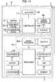
- FIG. 18shows a functional block diagram of functional components of an electrical appliance embodying the invention, including a reader unit for enabling detection of a replacement fascia; and
- FIG. 19shows an example of a vending system.
- FIG. 1illustrates a typical mobile telephone or cellphone 1 comprising a main body 5 and an attachable, and in this case also removable, fascia 3 .
- the fascia 3is formed with a user input array 9 which comprises a plurality of holes 11 for engagement with key pads (not shown) provided on the main body 5 of the mobile telephone 1 .
- the fascia 3is also provided with, in this example, a transparent plastics window 13 through which a liquid crystal display (LCD) (not shown in FIG. 1 ) provided on the main body 5 of the mobile telephone 1 can be viewed.
- the mobile telephone 1also comprises an aerial 7 which allows telecommunication signals to be transmitted and received.
- LCDliquid crystal display
- a passive data storage device 17Mounted upon, or embedded within, an inside surface of the removable fascia 3 is a passive data storage device 17 .
- the fascia 3will be moulded from a plastics material and the passive data storage device 17 encapsulated in a housing fitted to (for example embedded in or mounted to the surface of) the fascia 3 during the moulding process.
- the main body 5 of the mobile telephone 1carries a reader unit 15 .
- the reader unit 15is positioned such that, when the fascia 3 is fitted to the main body 5 , the passive data storage device 17 will be in range of, as shown will lie adjacent to, the reader unit 15 so that, as will be described in detail below, couplers of the passive data storage device 17 and reader unit 15 couple to enable the passive data storage device 17 to derive a power supply from a signal supplied by the reader unit 15 and, when so activated, to transmit control data contained in its memory.
- FIG. 2shows a functional block diagram of the mobile telephone 1 .
- the main body 5 of the mobile telephone 1comprises: a microphone 33 and a loudspeaker 31 enabling a user to input speech and hear audio output respectively; a user input device 25 (in this case a keyboard) enabling the user to input numbers to be called, other information and instructions for controlling various features of the mobile telephone 1 ; a display 37 on which incoming or outgoing telephone numbers, SMS text messages and other information can be displayed; and a transceiver 7 a which with the aerial 7 shown in FIG. 1 enables transmission and reception of communications over a mobile telecommunications network using, for example, the GSM (Global System for Mobile Communications), GPRS (General Packet Radio Service) or 3G (Third Generation, GSM) system, or future such networks.
- GSMGlobal System for Mobile Communications
- GPRSGeneral Packet Radio Service
- 3GThird Generation
- the above functional componentsare coupled, via appropriate interfaces (not shown) to a mobile telephone processor 23 which controls the overall operation of the mobile telephone 1 .
- the mobile telephone processor 23is associated with a non-volatile memory 29 which has a read-only portion which contains control operation software data and information data and a writable portion that, for example, enables storage of telephone numbers and messages input to the mobile telephone by the user or received by the mobile telephone over the mobile telecommunications network.
- the mobile telephone 1further comprises a subscriber identification module (SIM) 27 .
- SIM 27is a detachable module which provides user specific data and also algorithms and data specific to the operator of the mobile telecommunications service provider.
- the mobile telephone processor 23is coupled to the reader unit 15 via line 23 a.
- the reader unit 15comprises a reader 21 which is coupled to the mobile telephone processor 23 via line 23 a and which is also coupled to a first coupling element or coupler LC 1 arranged to couple to a similar second coupling element LC 2 (see FIG. 4 ) carried by the passive data storage device 17 when the replacement fascia or cover portion 3 is fitted to the main body of the mobile telephone.
- the components of the mobile telephone 1 and the reader unit 15will be powered by the battery of the mobile telephone 1 , although a separate power supply may be provided.
- FIG. 3shows an embodiment of the reader unit 15 which consists of the coupling element or coupler LC 1 and the reader 21 .
- the reader 21has a reader microprocessor or microcontroller 51 having a memory 53 which will generally be non-volatile but could be volatile if backed-up, for example battery backed-up.
- An oscillator 43 controlled by an oscillator controller 41 under the control of the reader microprocessor 51supplies an oscillator output signal to the coupling element LC 1 .
- the reader microprocessor 51controls the oscillator control 41 to control activation of the oscillator 43 and, in this embodiment, also controls the oscillator control 41 to interrupt the output of the oscillator 43 to provide a signal from which the data storage device 17 within the fascia 3 can derive a clock signal as will be described below.
- the first coupling element LC 1is also coupled to a demodulator 45 which enables the modulation to be recovered from an amplitude modulated signal.
- the recovered modulationis supplied to signal processor 400 which supplies a digital signal representing a string of binary ones and zeros to the reader microprocessor 51 .
- the reader microprocessor 51communicates with the mobile telephone processor 23 on data line 23 a (see FIG. 2 ) so as to affect the functionality or operating characteristics of the mobile telephone.
- FIG. 4shows a simplified block diagram of one example of a passive data storage device forming the detectable component 17 .
- the passive data storage device 17comprises a passive data storage unit 54 and the coupler or coupling element LC 2 .
- the passive data storage unit 54consists of a power deriver PD that derives a power supply for the passive data storage unit from the oscillator signal coupled from the reader unit 15 (shown in FIG.
- the passive data storage devicemay include a sensor S for reasons that will be set out below.
- FIGS. 5 and 6show, respectively, block diagrams illustrating one example of the reader unit 15 and one example of the passive data storage device 17 .
- the passive data storage device 17 and reader unit 15are adapted to communicate via inductive coupling and each of the couplers LC 1 and LC 2 consists of a parallel connection of a capacitor and an inductor C 1 and L 1 and C 2 and L 2 , respectively.
- the inductive couplersmay form a tuned circuit, although this is not necessary at short range.
- the optional sensor Sis not shown in FIG. 6 .
- the demodulator 45is a simple diode rectifier while the signal processor 400 consists of modulation level and threshold detectors 47 and 49 .
- the modulation level detector 47comprises a comparator 470 and an averaging circuit 471 controlled by the reader microprocessor 51 .
- the output from the demodulator 45is supplied to the positive input of the comparator 470 .
- the average of the output of the demodulator 45is supplied by the averaging circuit 471 to the negative or inverting input of the comparator 470 .
- the output of the comparator 470is supplied to the threshold detector 49 which supplies to the reader microprocessor 51 either a one or a zero, depending upon the relationship between the signal and the threshold.
- the oscillator controller 41is a logic circuit or a transistor switch which controls the oscillator 43 to switch on or off the carrier signal to the first coupling element LC 1 in accordance with a signal received from the reader microprocessor 51 and the averaging circuit 471 generally consists of an averaging capacitor connected between the inverted input of the comparator 470 and ground by a transistor switch or transmission gate which is controlled by the reader microprocessor 51 so as to be conducting while the carrier signal is present and after transients have settled but is off while the carrier is off and during carrier turn-on transients so that averaging is only carried out while there is a steady carrier signal.
- the power deriver PD of the passive data storage unit 54comprises series-connected diodes D 1 and D 2 and a capacitor C 4 coupled between the coupling element LC 2 and a junction J 1 between the anode of the diode D 1 and a cathode of the diode D 2 .
- the cathode of the first diode D 1is connected to a first power supply rail P 1 (Vdd) while the anode of the second diode D 2 is connected to a second power supply rail P 2 (Vss).
- the capacitor C 4 and the diodes D 1 and D 2act effectively as a voltage doubler enabling the peak to peak voltage of a received AC or oscillating signal inductively coupled to the passive data storage device 17 by the coupling elements LC 1 and LC 2 to be used by the diodes D 1 and D 2 to derive a power supply for the passive data storage device 54 from the oscillating signal.
- the controller 600comprises a clock signal deriver 600 c in the form of a missing pulse detector which is coupled to the junction J 1 to derive a clock signal for the data storage unit 54 from the interrupted oscillator signal supplied by the oscillator 43 and an address counter 600 a clocked by the clock signal.
- the controller 600may also include a reset switch 600 b to reset the counter 600 a if the passive data storage device 54 is not powered for a predetermined time.
- the controller 600causes data to be read out from the data store 59 directly to the modulator M which comprises a series-connection of a FET T 1 and a capacitor C 3 coupled across the capacitor C 2 of the coupler LC 2 .
- an output 59 a of the data store 59is coupled to the gate of the FET T 1 .
- the data store 59is a serial read-only memory (ROM). It may, however, be any form of non-volatile memory that does not require battery backup such as a ROM, an EE-PROM (electrically erasable programmable ROM), a flash memory, F-RAM and so on.
- the coupling element LC 1 of the passive data storage device 17lies adjacent and in close proximity to the coupling element LC 2 of the reader unit 15 , inductively coupling the passive data storage device 17 to the reader unit 15 .
- the oscillator 43 of the reader 21generates a high or RF (radio frequency), typically 13.56 MHz (MegaHertz), signal which is supplied to the first coupling element LC 1 and inductively coupled to the passive data storage device 17 via the second coupling element LC 2 .
- the voltage doubler formed by capacitor C 4 and diodes D 1 and D 2thus derives a power supply for the passive data storage device and, when powered, the clock deriver 600 c derives a clock signal from the interrupted oscillator signal and control data is output from the data store 59 on output 59 a under the control of the counter 600 a.
- control dataWhen control data is output by the data store 59 on the output line 59 a , the data switches the FET T 1 .
- the loading across the inductor L 2varies in dependence upon whether the FET T 1 is conducting or non-conducting, causing the oscillating signal to be modulated in accordance with the control data output from the data store 59 .
- the control data output from the data store 59is extracted from the modulated oscillating signal by the demodulator 45 , modulation level detector 47 , threshold detector 49 and reader microprocessor 51 to provide a data input signal to the mobile telephone processor 23 ( FIGS. 2 and 3 ) representing the data output from the data store 59 .
- control data output from the data store 59 and downloaded by the reader microprocessor 51 ( FIG. 5 ) to the mobile telephone processor 23 ( FIG. 2 )may then be stored in the writable portion of the memory 29 .
- This control datamay comprise at least one of software data, that is computer code executable or implementable by the mobile telephone processor 23 , and information data that is stored in the memory 29 so as to be usable by the mobile telephone processor 23 .
- the data downloaded from the passive data storage devicemay include upgrades or modifications of the mobile telephone processor software where the fascia is supplied by or under licence from the manufacturer or supplier of the mobile telephone. Additionally or alternatively, software data may include updates or modifications to existing games software provided with the mobile telephone or new games software.
- Information datamay be provided as an alternative to or in addition to software data.
- Examples of information data that may be stored by the data store 59include dialling or ringing tones and telephone numbers, Internet addresses and/or WAP addresses enabling, for example, the supplier of the fascia to attract buyers by supplying new ringing tones and/or to advertise itself or other companies by supplying their telephone numbers, Internet addresses or WAP addresses.
- Other examples of control datamay include graphics data, audio data, image data, video data, biometric data, mobile telephone services, subscription services, network services, promotions, advertisements and so on.
- control data stored by the passive data storage deviceconsists of the actual software and/or information data or the identity or address of the user's mobile network provider or another third party, service provider.
- control data stored by the passive data storage devicemay be access data that enables the user to access such software and/or information data.
- this access datamay consist of a mobile telephone number or a WAP address that the user of the mobile telephone can contact to download new software data and/or information data or the identity or address of the user's mobile network provider or another, third party, service provider.
- downloading of access datamay cause the mobile telephone processor 23 to make additional facilities for which the mobile telephone processor is already programmed but that are currently barred from the user available to the user, for example facilities such as international calling access, voicemail and message-taking facilities.
- access datamay cause the mobile processor 23 to enable the user to access data previously stored in the memory 29 but not accessible to the user.
- datamay include information data such as ringing tones, telephone numbers and/or WAP addresses and software data such as modifications to the processing software of the mobile telephone and/or upgrades or modifications to games software already available to the user or new games software.
- the access datamay be, for example, an identity code that enables the mobile telephone processor 23 to identify the particular type of fascia 3 by comparison with data stored in its memory.
- the mobile telephone processor 23may then control the mobile telephone functionality and capability available to the user in accordance with the identified fascia 3 .
- the mobile telephone processormay be programmed so that, if it receives no control data or receives incorrect or non-understandable control data (for example if it receives the wrong access or identity code data), then the mobile telephone processor 23 may determine that the fascia is a counterfeit or unrecognised fascia and may modify or restrict the functionality of the mobile telephone.
- the mobile telephone processor 23may inhibit access to all or certain optional features or functions and may continue to inhibit use of those optional features or functions until a genuine fascia is fitted to the mobile telephone.
- the mobile telephone processor 23may simply limit the number of functions available via the mobile telephone, for example the mobile telephone processor 23 may limit the available number of ringing or dialling tones or message taking options, for example, or may “lock” the mobile telephone so that only emergency outgoing calls may be made.
- the mobile telephone processor 23may also display a message to the user to alert them to the fact that the replacement fascia is not genuine. Where the use of a non-genuine replacement fascia is not detrimental to the functioning of the mobile telephone and does not potentially detrimentally affect the safety of the user, then the mobile telephone processor 23 may simply display a message to the user on the display 37 to alert the user to the fact that the fascia is not genuine.
- the mobile telephone processormay also be programmed to enable it to identify genuine replacement fascias for other models of mobile telephone and to cause the display 37 to display to the user a message alerting them to the fact that the incorrect replacement fascia has been fitted if the mobile telephone processor determines that incorrect identity data has been received.
- the passive data storage deviceis powered and so supplies its stored data to the reader unit 15 whenever the first and second coupling elements LC 1 and LC 2 are inductively coupled.
- the reader microprocessormay send the received data continually or periodically to the mobile telephone processor 23 .
- Continually powering the passive data storage device 17may, however, present a drain on the battery of the mobile telephone.
- the reader microprocessor 51may be programmed to cause the oscillator control 41 to switch on the oscillator 43 only at predetermined intervals so that the passive data storage device 17 is periodically activated to send its data.
- part of the encapsulating housing of the passive data storage device 17may carry a conductive strip ( 17 a in FIG. 1 ) that, when the fascia 3 is coupled to the main body 5 , couples a pin ( 51 a in FIG. 5 ) of the reader microprocessor 51 to ground or earth and the reader microprocessor 51 may periodically check the status of that pin.
- the reader microprocessor 51detects that the voltage at the pin 51 a has gone high then it determines that the fascia 3 has been removed and when it detects that the voltage at that pin has again gone low it determines that either the fascia 3 has been refitted to the main body 5 or a different fascia 3 has been fitted and so activates the oscillator control 41 to switch on the power oscillator 43 to power up the passive data storage device 17 .
- the passive data storage device 17will be powered up to transmit its data only when a replacement fascia 3 or cover portion is fitted to the main body 5 .
- the passive data storage device 17is a synchronous passive data storage device, that is the clock signal of the passive data storage device 17 is controlled by and so synchronised with the reader microprocessor 51 .
- the passive data storage device 17may be an asynchronous device, that is the clock deriver 600 c coupled to the junction J 1 shown in FIG. 6 may be replaced by a clock signal generator which is powered up when a power supply is derived by the passive data storage device to generate an independent clock signal for the passive data storage device.
- the passive data storage device 17may incorporate a microcontroller that controls read out of data from the data store 59 which may enable different areas of the data store 59 (and so different data) to be accessed and read out in accordance with instructions supplied by the reader microprocessor 51 . Such instructions may be transmitted by representing 0 and 1 as long and short duration interruptions of the oscillator signal.
- the passive data storage devicemodulates the signal received from the reader by, under control of the counter 600 a and clock divider 600 c , reading data out of the data store 59 .
- FIG. 7shows an example of another passive data storage device 17 ′ that may be used in place of the passive data storage device 17 shown in FIG. 6 .
- This data storage deviceuses a different controller from that shown in FIG. 6 .
- the controllercomprises a control engine 330 arranged to recognise a number of different codes (in the form of predetermined sequences of ones and zeros) transmitted to it by the reader microprocessor 51 .
- the reader microprocessor 51is arranged to transmit ones and zeros by causing the oscillator control 41 to interrupt the output of the oscillator 43 for short and long durations, respectively.
- a clock signal for the control engine 330is derived from the signal supplied by the oscillator 43 by a first signal deriver 350 in the form of a fast missing pulse detector coupled to junction J 1 while the control engine 330 is arranged to extract the data transmitted by the reader 17 ′ using the output of the first signal deriver 350 and the output of a second signal deriver 360 in the form of a slow missing pulse detector also coupled to the junction J 1 .
- the timeout periods of the fast and slow missing pulse detectorsare set so that the output of the fast missing pulse detector will have one of two widths dependent upon whether the particular data bit is a binary “zero” or a binary “one” while the slow missing pulse detector will provide a pulse only when a particular data bit is a binary “one”.
- the control engine 330can thus determine from the outputs of the first and second signal derivers 350 and 360 whether a received bit is a binary “zero” or a binary “one”. As set out above, the control engine 330 is programmed to enter a number of different states dependent upon the instruction code received from the reader unit 15 . These different states may cause the control engine to read out data from different areas of the data store 59 .
- the data store 59may, however, be an electrically erasable memory in which case at least one of the states of the control engine 330 may enable the control engine to erase the data in a portion of the data store 59 and to write new data supplied by the reader unit 15 into the data store 59 .
- the mobile telephone processormay be programmed to place a time limit on the availability of the additional functions provided by the data stored in the data store 59 .
- control engine 330is a state machine with its own non-volatile memory it will, of course, be appreciated that the state machine may be replaced by an appropriately programmed microprocessor or microcontroller also having its own memory. Also, different methods for communicating instructions from the reader unit 15 to the control engine 330 may be used.
- the data store 59may also be used to extend the memory capacity of the mobile telephone to store further telephone numbers and/or other data.
- the passive storage device 17may also be used to provide a record of historical degree and frequency of use of the mobile telephone. Further details of the writing and reading operations that may be carried out by the control engine 330 are to be found in UK Patent Application number: 0031518.4 or the corresponding PCT application number GB01/05690, the whole contents of each of which are hereby incorporated by reference. Data may also be written to the mobile telephone SIM card by the reader unit and mobile telephone processor.
- the actual components of the user interface keypads or keyboardare carried by the main body of the mobile telephone and the fascia 3 simply provides apertures through which the keypads extend.
- FIG. 8shows a functional block diagram, similar to FIG. 2 , of another example of a mobile telephone in accordance with the present invention.
- This mobile telephonediffers from that shown in FIG. 2 in that the user input device 25 , in this example the keyboard, is provided within the fascia 3 and is arranged to communicate with a passive data storage device 170 that, when the fascia 3 is fitted to the main body 5 of the mobile telephone, derives a power supply from the signal supplied by the reader oscillator 43 as described above and, in response to input by the user to the user input device 25 , communicates this input to the reader unit 15 by modulating the oscillator signal in a manner similar to that described above.
- the fasciamay include an optional sensor S coupled to the passive data storage device.
- FIG. 9shows a functional block diagram of the passive device 170 .
- This passive data storage deviceis similar to that shown in FIG. 7 with the controller 600 ′ having the configuration described above with reference to FIG. 7 (that is it will include a control engine in the form of a state machine, microprocessor or microcontroller with its own memory).
- the passive data storage device 170differs from that shown in FIG. 7 in that the controller 600 ′ incorporates a keypad or keyboard scanner (either by programming the controller or possibly by providing a dedicated user input interface) to enable it to communicate with the user input device 25 shown in FIG. 8 and, in response to keystrokes made by the user of the user input device 25 , to communicate to the reader unit 15 shown in FIG.
- the passive data storage device 170communicates this data in the same manner as described above, that is by the controller 600 ′ causing the modulator M to modulate the oscillator signal supplied by the reader unit 15 unit in accordance with the data to be transmitted.
- the data store 59stores control data of the type described above, that is software data and/or information data that affects the functionality of the mobile telephone.
- the controller 600 ′ of the passive data storage device 170is programmed so as to download or communicate to the reader unit 15 control data from the data storage device 170 when the fascia is first fitted or first refitted to the main body 5 of the mobile telephone 1 and then subsequently to monitor keypad activation by the user and to communicate keystrokes input by the user to the reader unit 15 as described above.
- Placing the entirety of the keyboard in the fascia 3means that it is not necessary for the interior shell of the main body 5 of the mobile telephone to be riddled with holes corresponding to the keypad (which reduces the efficacy of any electromagnetic interference (EMI) shielding). Rather, the manufacturer of the mobile telephone should be able to use a continuous shielding layer, apart from coupling connections required to connect to the display.
- EMIelectromagnetic interference
- Providing the entirety of the user input device 25 within the fascia 3means that the mobile telephone may be fitted with different fascias for different applications, for example, a mobile telephone fascia that facilitates use as a mobile telephone and a games fascia that facilitates playing of a game.
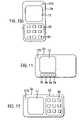
- FIGS. 10 and 11illustrate schematically examples of the front surfaces of two such fascias 3 a and 3 b .
- the display window 13has the same size and dimension but in FIG. 11 the display window 13 and user input device 25 are arranged so that the display is viewed in a landscape orientation while in FIG. 10 the display is viewed in a portrait orientation.
- the fascia 3 a shown in FIG. 10has a keyboard 25 with a keypad 90 arrangement similar to that indicated by FIG. 1 .
- the keyboard 25is replaced by games key inputs 9 a each of which corresponds to a gaming control function, analogous to those present on a computer games console.
- Separating the user input device 25 from the main body 5 of the mobile telephoneenables the position, type, number and size of the keys 9 a , 90 to be varied without affecting the functionality of the main body of the mobile telephone. All that is required is that the mobile telephone processor can identify from control data downloaded from the passive data storage device 170 when the fascia is first fitted, the type of user input device 25 and can then respond to the key stroke data code communicated to it from the passive data storage device 170 . The control data also enables the mobile telephone processor to determine the use orientation of the display and to control the LCD accordingly.
- a dedicated games fasciamay be provided.
- the keypadsthemselves may be differently constructed so that, for example, soft more reactive keypads may be provided in the games fascia to allow better, faster game play.
- fasciasmay be provided for these options so that, for example, instead of a mobile telephone type keypad, a fascia adapted for word processing may carry, providing sufficient space is available, a full QWERTY type keyboard.
- PDApersonal digital assistant
- a small minimalistic user input device 25 with a limited number of keypadsmay be provided.
- fascias having a “restricted use” user input devicemay be fitted that restricts the functions of the mobile telephone that the younger family member can access.
- the passive data storage devicemay store “macros” relating to certain keys allowing, for example, high speed input of words that relate to that particular fascia.
- a fascia designed for use by football supportersmay have words such as “goal”, “net”, “idiot!” and so on associated with keys of the fascia
- a business fasciamay have a passive data storage device that stores macros for phrases such as “call you later”, “meet me at”, “time”, in each case facilitating, for example, the sending of text messages.
- the user input deviceis independent of the main body or mother unit of the mobile telephone, the actual keypads may carry visual identifiers identifying the macros with which they are associated.
- the passive data storage devicemay contain as part of the control data, spell checkers, crosswords, word translators, dictionaries etc facilitating use of the mobile telephone as an educational tool.
- the user input interface deviceis independent of the main body 5 of the telephone, specialist keypads that enable greater levels of touch or pressure sensitivity may be provided and the controller 600 ′ of the passive data storage device programmed to respond to different degrees of touch or pressure in a predetermined manner enabling, for example, different types of characters for example, upper, lower, bold, italics and so on, to be generated dependent on how hard the key is pressed.
- Such a fasciamay also be specifically adapted to facilitate drawings of graphics with different keys controlling drawings of lines in different directions with the extent or thickness of the line being determined by the user pressure on the keypad or even some of the keypads being associated with simple graphical shapes such as circles, squares etc.
- the passive data storage device and mobile telephone processormay also be programmed to communicate data relating to musical notes and, for example, a dedicated fascia may be provided that enables the user to create tunes using different levels of pressure of touch to change the note or key, for example.
- a fasciamay also be specifically adapted to enable its use by a person with a disability.
- the fasciamay be specifically adapted for use by a person having, for example a physical, visual, hearing or mental disability.
- a fasciamay be specifically adapted for use by a visually impaired or blind person by providing the user input with specific tactile features; a fascia may be specifically adapted for use by a hearing impaired or deaf person by providing the user input with a speech-to-text facility that enables a telephone text mode; a simplified fascia may be provided with symbols and icons for people with learning difficulties; and a fascia may be provided that enables single switch operation by scanning for people with physical disabilities.
- a fasciamay provide a link to a telephone relay service such as “Typetalk” for use by hearing impaired or deaf people.
- the passive data storage devicemay contain an orientation sensor (shown as sensor S in FIGS. 4 and 8 ) that enables the controller of the passive storage device to determine the orientation of the mobile telephone and thus of the fascia so that, when the mobile telephone is in the orientation shown in FIG. 10 , the passive data storage device instructs the mobile telephone processor to control the display in the portrait orientation while when the mobile telephone is in the orientation shown in FIG. 12 , the passive data storage device instructs the mobile telephone processor to control the LCD display in landscape orientation, facilitating its use for graphics and games play.
- the user input device 25itself would be physically identical in both orientations but the control signals supplied by the controller of the passive data storage device to the main body 5 of the mobile telephone in accordance with keystrokes made by the user will depend upon the orientation of the fascia.
- the fasciamay carry a user input, for example one of the keypads that, when depressed, instructs the controller of the passive data storage device to communicate with the mobile telephone processor so that the orientation of the display is switched from portrait to landscape or vice versa.
- the optional sensor S shown in FIGS. 4 and 8need not necessarily be an orientation sensor but could be, for example, an environmental sensor sensitive to any one or more of temperature, humidity, sound, odour, a fluid, a gas, water, magnetic field, radio frequency, infra red, vibration, a chemical, pressure, for example, e.g. a barometrics sensor, orientation, position, height, or light that provides, via the first and second couplers, a signal regarding the environmental conditions to the reader unit that affects the overall operation of the mobile communications device.
- an environmental sensorsensitive to any one or more of temperature, humidity, sound, odour, a fluid, a gas, water, magnetic field, radio frequency, infra red, vibration, a chemical, pressure, for example, e.g. a barometrics sensor, orientation, position, height, or light that provides, via the first and second couplers, a signal regarding the environmental conditions to the reader unit that affects the overall operation of the mobile communications device.
- the reader unitmay be supplied with a low light signal that automatically causes the processor of the mobile communications device to activate a back light or where the sensor senses noise level the reader unit may cause the mobile telephone audio volume to be raised or lowered depending upon the ambient noise sensed by the sensor.
- the reader unit 15is, as shown in FIG. 2 , separate from the main components of the mobile telephone.
- the reader unit 15may, however, be provided within the main components of the mobile telephone.
- the reader unitmay be provided in the SIM card so that it is not necessary to adapt the reader unit for different hardware.
- the user input device 25 carried by the fasciais the keyboard or key input. It may, however, also be possible to incorporate into the fascia 3 a or 3 b within the window 13 a substantially transparent touch sensitive array such as a capacitive array that enables a user to input commands using their fingers or a stylus.
- the keyboardmay be omitted and the display may display soft keys that are activatable by the user using the stylus or a finger.
- the mobile telephone processormay then be programmed to display different types of soft keys when the fascia is used in the landscape rather than the portrait orientation and, of course, different types of soft keys may be provided on different types of fascias.
- the user input device and passive data storage device 17are provided in a fascia for the mobile telephone. This need not necessarily be the case.
- the mobile telephonemay have a conventional fascia or a fascia such as that shown in FIG. 1 but without the passive data storage device and a separate user interface device having a passive data storage device and the functional components shown in FIG.
- the controller of the passive data storage devicecauses control data to be read from the data storage device so as to modulate the oscillating signal to communicate to the mobile telephone instructions to the mobile telephone processor that it is to ignore the in-built user interface and to receive user input instructions from the user input device.
- a separate lightweight, non-self-powered user interface devicehaving as the user interface device at least one of a keypad, keyboard, touch screen, joystick, finger print device, and digitizing tablet that enables the user, by bringing the separate user interface device into contact with or in proximity to the mobile telephone, to override the normal user interface of the telephone and to use the user interface device to facilitate, for example, playing of games software or, where the user interface device enables a QWERTY type keyboard layout, to facilitate entering of text messages or notes. It may also be possible to provide the display in the fascia.
- data carried by the passive data storage deviceaffects the functionality or capabilities of the mobile telephone.
- the reader processormay be programmed so as to automatically cause the mobile telephone processor to switch the mobile telephone from a standby mode to an active mode only when the fascia is correctly fitted to the main body, thereby preventing any accidental operation of the mobile telephone with its fascia removed.
- Some examples of mobile telephonesinclude a movable, for example hinged, cover or lid.
- the passive data storage devicein order for the passive data storage device to communicate with the reader unit when the cover is in the open, working condition, the passive data storage device should be appropriately located in the cover portion so as to be close to the reader unit when the cover or lid is in the open condition.
- a passive data storage devicemay be located in a part of the cover portion, for example, remote from a hinge, such that the couplers LC 1 and LC 2 are only coupled when the cover or lid is closed and the mobile telephone processor may be programmed to move from a standby to a full active mode when the reader unit provides a signal indicating that the first and second couplers LC 1 and LC 2 are no longer coupled.
- the passive data storage devicecontains at least a non-volatile memory and may also include processor capabilities.
- the reader processor 51may, however, be programmed simply to determine whether or not a detectable component or a particular type of detectable component is coupled to the coupler LC 1 and to advise the mobile telephone processor device accordingly.
- the detectable componentmay simply consist of a coupler that couples to the reader coupler so as to change its characteristics.
- the detectable componentmay simple consist of the inductive coupler LC 2 which, when inductively coupled to the reader coupler LC 1 , affects its resonant frequency or Q factor.
- the couplermay consist simply of an inductor that has the same effect when coupled to the coupler LC 1 .
- fasciamay have, for example, different inductance and, as the case may be, capacitance values enabling the reader unit 15 to distinguish different fascias and to communicate this information to the mobile telephone processor so as to affect the functionality of or operating characteristics of the mobile telephone as described above.
- the inductancemay be provided by Litz wire, increasing the sensitivity of the coupling.
- the inductive couplermay include, in series with the inductance, a resistance formed of material exhibiting the GMI (Giant Magneto Impedance) effect, that is a material that has a skin resistance that, when a relatively high frequency oscillating signal is supplied through the material, varies with magnetic field.
- the resistive componentmay be formed of, for example, a cobalt, amorphous alloy.
- the coupling element LC 2may consist simply of a loop of GMI wire or ribbon.
- a loop of GMI wire or ribbonmay be associated with the inductance of the inductive coupler LC 2 .
- a separate capacitormay or may not be provided.
- the oscillator 43will provide the high frequency oscillating signal and the reader unit will also include a relatively low frequency pulsed oscillator.
- coupling of the first and second inductive couplerscauses a decrease in the amplitude in the carrier signal flowing through the inductive L 1 with its amplitude being modulated in accordance with the change in resistance of the resistive GMI component due to the magnetic field generated by the pulsed low frequency oscillator.
- the passive data storage device 17uses amplitude modulation to transmit data to the reader unit 15 . It will, however, be appreciated that frequency modulation may be used as may phase modulation as described in WO 97/23060 (PCT/GB96/02975), the whole contents of which are hereby incorporated by reference.
- the first and second coupling elementsare arranged to couple inductively.
- the first and second coupling elementsmay be arranged to couple in any other manner that requires the first and second coupling elements to be in close proximity but not in physical contact with one another.
- the first and second coupling elementsmay be arranged to couple capacitively.
- FIG. 13shows a functional block diagram of another example of a mobile telephone 1 ′ embodying the invention which differs from the mobile telephone described above with reference to FIGS. 2 , 3 and 4 in a number of ways.
- the connections of the various functional components of the passive data storage device 17 (other than the controller 600 ) to the power deriver PDare not shown in FIG. 13 .
- the processor 23 and memory 29 of the mobile telephonealso carry out the functions of the reader processor 51 and reader memory 53 shown in FIG. 3 so that these components need not be present in the reader unit 15 .
- derivation of power by the passive data storage device 17 and data communication between the passive data storage device 17 and the reader unit 15is achieved by an electrical wire connection between a reader transceiver RT of the reader unit 15 and a storage device transceiver ST of the passive data storage device.
- the reader transceiver RTthus replaces the oscillator controller 41 , oscillator 43 and coupler LC 1 shown in FIG. 3 while the storage device transceiver ST replaces the modulator M and coupler LC 2 shown in FIG. 4 .
- the reader transceiver RT and storage device transceiver STmay communicate data by any conventional modulation technique, for example amplitude, frequency, pulse code modulation and so on.
- the fascia 3also includes an illumination device to provide a backlight for the user input device 25 .
- the illumination device 250may be, for example, one or more, light emitting diodes (LEDs) and the controller 600 may include an LED matrix driver.
- LEDslight emitting diodes
- the fascia 3may also include a sensor S as described above.
- the sensor Smay be, for example, a sound sensor that causes the controller 600 to switch on or flash the LEDs in response to sound so enabling, for example, a visual indication of a ringing tone.
- the sensor Smay be an optical input that enables direct communication with an external keypad or personal digital assistant.
- the reader unit 15includes an oscillator 43 and oscillator controller 41 for generating a high frequency or RF signal from which components carried by the fascia 3 derive a power supply and via which data communication between the passive data storage device 17 and the reader unit 15 occurs.
- FIG. 14shows a functional block diagram, similar to FIG.
- FIG. 13of another example of a mobile telephone 1 A embodying the present invention wherein the oscillator and oscillator control are omitted from the reader unit and the couplers LC 1 and LC 2 are tuned to the RF signal emitted by the antenna 7 of the mobile telephone so that the components carried by the fascia 3 derive a power supply from the RF signal transmitted by the mobile telephone and data communication between the passive data storage device 17 and the reader unit is achieved in the manner described above with reference to FIGS. 6 and 7 by varying the loading of the inductive coupler LC 2 to provide an amplitude modulated signal. Frequency or phase modulation may also be used, however amplitude modulation is more desirable as it should not interfere with the mobile telephone GSM signal.
- the mobile telephone 1 ′′ shown in FIG. 14is similar to that shown in FIG. 13 .
- the tuning of the inductive coupler LC 2 to the frequency of the RF signal transmitted by the antenna 7enables the power deriver PD to derive a power supply for the passive data storage 17 from the RF signal transmitted by the mobile telephone.
- the passive data storage device 17When powered-up, the passive data storage device 17 transmits data stored in the data store 59 by modulating the RF signal.
- the positioning of the reader unit 15 on the main body of the mobile telephone and the positioning of the passive data storage device 17 on the facia 3are such that the coupler LC 1 is positioned very close to (within 8 mm of) the coupler LC 2 and accordingly will pick up the modulation from the passive data storage device 17 .
- Thisenables the passive data storage device to communicate its identity code to the processor 23 of the mobile telephone 1 ′′ upon powering-up of the mobile telephony RF carrier signal.
- the coupler LC 2is, in this example, also positioned between the antenna 7 and the coupler LC 1 to shadow or hide the coupler LC 1 from the RF signal supplied by the antenna so that the signal supplied by the data storage device is not swamped by the antenna signal.
- the processor 23 of the mobile telephonemay be programmed to expect an identity code from the signal processor 400 of the reader unit 15 upon power-up so that there is no need for any handshaking operation.
- the controller 600 of the passive data storage devicemay be programmed to transmit its identify code a number of times, for example three times, and then to cease modulation of the RF signal transmitted by the mobile telephone 1 ′′ until, after the mobile telephone has ceased transmitting, the mobile telephone next commences transmission of its RF signal.
- the processor 23 of the mobile telephonemay be programmed to send a clean, unmodulated, RF signal for a few milliseconds before commencing frequency modulation in accordance with the GSM standard so that the RF signal that the passive data storage device modulates is clean, that is unmodulated. This should, however, not be necessary where the passive data storage device uses amplitude modulation to convey its data to the reader unit 15 .
- FIG. 15shows a functional block diagram similar to FIG. 14 of another example of a mobile telephone 1 a embodying the present invention where, as in FIG. 14 , the passive data storage device 17 derives its power supply from the RF signal transmitted by the antenna 7 a of the mobile telephone. However, in this case, communication of data between the passive data storage device 17 and the reader unit 15 is effected by data communicators DC 1 and DC 2 .
- the data communicators DC 1 and DC 2may simply establish an electrically conductive path between the controller 600 when the fascia 3 is coupled to the main body of the mobile telephone so that data is supplied directly from the controller 600 to the signal processor 400 .
- the data communicators DC 1 and DC 2may communicate optically with the data communication DC 2 having a light emitting device which is caused to flash on and off by the controller 600 to transmit data stored in the data store 59 and the communicator DC 1 having a light receiving device such as a photodiode or phototransistor for receiving light emitted by the light emitting device of the data communicator DC 2 .
- the data communicators DC 1 and DC 2may each have optical transceivers so that data can also be communicated optically from a light-emitting device of the data communicator DC 1 to a light receiving device of the data communicator DC 2 .
- the data communicators DC 1 and DC 2may be configured to communicate acoustically.
- the data communicator DC 1may be a microphone and the data communicator DC 2 a loudspeaker with, in this case, data being communicated from the passive data storage device to the data communicator DC 1 as acoustic signals, preferably short pulses.
- the microphone 33 of the mobile telephoneit may be possible to use the microphone 33 of the mobile telephone as the data communicator DC 1 .
- acoustic coupling between the data couplers DC 1 and DC 2may be achieved by the use of piezoelectric transducers.
- Other forms of data communication between the data communicators DC 1 and DC 2may be used such as, for example, mechanical vibration, electrostatic and electromagnetic signals.
- the passive data storage device 17when the mobile telephone 1 a starts to transmit its RF signal, the passive data storage device 17 is powered and the controller 600 then causes data from the data store 59 to be communicated by the data communicator DC 2 to the data communicator DC 1 of the reader unit.
- the passive data storage deviceremains powered while the mobile telephone is powered and a keyboard scanner included within the controller 600 receives data from the user input keypad or keyboard and communicates this to the reader unit 15 .
- the embodiments shown in FIGS. 13 to 15may, however, be modified so that the user input device (and any associated illumination device) form part of the main body of the mobile telephone as in the embodiment described with reference to FIGS. 2 to 4 . Incorporating the keypad or keyboard into the facia 3 has, however, significant advantages as discussed above with reference to FIGS. 8 to 12 .
- the passive data storage devicemay comprise an application specific integrated circuit (ASIC) with the data store 59 comprising, for example, an electrically erasable memory, enabling the keyboard scanner software to be configured at factory level to co-operate with the particular type of keypad or keyboard carried by the particular cover into which the passive data storage device is to be incorporated.
- ASICapplication specific integrated circuit
- FIGS. 2 to 12may be modified so that the mobile phone processor 23 carries out the functions of the reader processor 51 so that, the reader unit 15 need not include the reader processor 51 and reader memory.
- the embodiments of FIGS. 13 to 15may have reader units incorporating the reader processor and memory.
- the embodiments described above with reference to FIGS. 2 to 12may be modified to use the power derivation and data communication schemes described above with reference to FIGS. 13 , 14 or 15 .
- the data communicators DC 1 and DC 2may be used where the passive data storage device is powered via the reader unit rather than the mobile telephone antenna
- coupling between the passive data storage device 17 and the reader unit 15may be via a coupling arrangement such as described in the applicants co-pending published International Application No. WO00/31676 may be used and the whole contents of that document are hereby incorporated by reference.
- FIG. 16shows a functional block diagram of a computing device such as a PDA (personal digital assistant) or games console 100 which differs from the mobile telephone shown in FIG. 2 in that the SIM card is replaced by a removable disk drive 30 for receiving a removable disk RD, and the transceiver is replaced by a communications interface 38 which may be a MODEM.
- the control datamay comprise software data in the form of new software and/or upgrades for existing software provided on the PDA including, for example, games software, wordprocessing, spread sheet and other applications software.
- the control datamay alternatively or additionally include information data such as, for example, tunes and images that may be played via the loudspeaker 31 or shown on the display 37 under control of the processor 23 .
- the control datamay alternatively be in the form of access data that enables the reader unit 15 to instruct the processor 23 where to obtain data represented by the access data by, for example, accessing a particular site on the Internet or another network using the communications interface.
- Such datamay be pre-stored in the memory 29 , or available via the communications interface 38 .
- the reader unit and data storage device of this computing apparatusmay have any of the configurations described above where the mobile telecommunications transceiver can be replaced by the communications interface, that is any of the configurations that do not require the data storage device to derive a power supply from the mobile telecommunications transceiver signal.
- Embodimentswill now be described of electronic devices or electrical appliances having an attachable functional component such as, for example, a replaceable tool will be described.
- FIG. 17shows a diagrammatic perspective view of a domestic power tool 60 while FIG. 18 shows a functional block diagram of the electrical appliance 60 .
- the electrical appliancemay be mains or battery powered, having a number of different attachable components comprising or arranged to carry tools for performing different tasks.
- the power tool main body 61is carrying a replaceable component in the form of a chuck assembly 63 having a chuck 64 for receiving, for example, drill bits or screwdriver heads.
- FIG. 17also shows a further attachable component that may be fitted to the main body 61 of the power tool in place of the chuck assembly.
- the further attachable component 65is a sander assembly having a sander foot 66 for receiving a sanding sheet 67 .
- the main body 61has an outer plastics, generally moulded, casing. Coupling between the main body 61 and an attachable component 63 or 65 is effected via the drive shaft of a motor (not shown in FIG. 17 ) of the power tool.
- a plastics coupling collar 63 a or 65 a of the replaceable componentis fitted onto a portion of the casing of the main body 61 .
- a passive data storage device 17is fitted to, generally embedded within, the coupling collar 63 a or 65 a while a reader unit 15 is housed within the casing of the main body together with the other control circuitry of the power tool.
- the reader unit 15is positioned such that, when the attachable component 63 or 65 is fitted to the main body 61 , the passive data storage device 17 will be in range of, as shown will lie adjacent to, the reader unit 15 so that, as will be described in detail below, couplers of the passive data storage device 17 and reader unit 15 couple to enable the passive data storage device 17 to derive a power supply from a signal supplied by the reader unit 15 and, when so activated, to transmit control data contained in its memory.
- the main body 61comprises, in addition to the reader unit 15 , a controller such as a microprocessor or microcontroller 23 which controls the overall operation of the power tool 60 .
- the controller 23may be associated with a non-volatile memory 29 which has a read-only portion which contains control operation software data and information data and a writable portion.
- the controller 23is coupled to a motor 270 for driving the attachable tool in known manner and also to a user interface 25 consisting of a user input device 72 which will generally, as is known in the art and as shown in FIG. 17 , consist of an on/off switch 68 and possibly also a speed control 69 .
- the user interfacemay also include one or more indicator lights 80 and a rudimentary loudspeaker 81 that, under control of the controller 23 , may issue audible warnings to the user under certain circumstances.
- the power tool 60is battery operated and the control circuitry 50 in the main body also includes a battery 73 .
- the couplings between the battery 73 and the various components of the control circuitry, apart from the controller 23are not shown in FIG. 18 .
- the reader unit 15comprises a reader 21 which is coupled to the controller 23 via line 23 a and to a first coupler or coupling element LC 1 .
- the first coupling element LC 1is arranged to couple to a similar second coupling element LC 2 (see FIG. 4 ) carried by the passive data storage device 17 when the attachable tool 63 or 65 is fitted to the main body of the appliance.
- the reader unit 15 and the passive data storage device 17are as described above with reference to FIGS. 3 to 6 .
- the coupling element LC 1 of the passive data storage device 17lies adjacent and in close proximity to the coupling element LC 2 of the reader unit 15 , inductively coupling the passive data storage device 17 to the reader unit 15 and data is output by the passive data storage device 17 and read by the reader unit as described above with reference to FIGS. 3 to 6 .
- the control data output from the data store 59is extracted from the modulated oscillating signal by the demodulator 45 , modulation level detector 47 , threshold detector 49 and reader microprocessor 51 to provide a data input signal to the controller 23 representing the data output from the data store 59 .
- control data output from the data store 59 and downloaded by the reader microprocessor 51 to the controller 23may then be stored in the writable portion of the memory 29 .
- This control datamay comprise at least one of software data, that is computer code executable or implementable by the controller 23 , and information data that is stored in the memory 29 so as to be usable by the controller 23 .
- the data downloaded from the passive data storage devicemay include upgrades or modifications of any electrical appliance software where the attachable component is supplied by or under licence from the manufacturer or supplier of the electrical appliance.
- the control datamay be, for example, an identity code that enables the controller 23 to identify the particular type of attachable tool by comparison with data stored in its memory. The controller 23 may then control the functionality and capability available to the user in accordance with the attachable tool.
- the controller 23may control at least one of the speed, drive direction and duration of the operation of the motor 270 in accordance with the control data received by the reader microprocessor.
- the controller 23may inhibit operation of the electrical appliance if the reader microprocessor receives no control data or receives incorrect or non-understandable control data, for example if the reader microprocessor receives the wrong access or identity code data. This would ensure that, for safety reasons, the electrical appliance is not accidentally operated with an inappropriate tool fitted and for both safety and power saving purposes would ensure that the electrical appliance is not accidentally operated when no tool is attached. Where an incorrect tool is fitted, then the reader microprocessor may cause the controller 23 to cause the warning light 80 to flash or the loudspeaker 81 to emit an audio signal such as an audible warning beep.
- the passive storage devicemay also be used to provide a record of historical degree and frequency of use of the attachable tool. Further details of the writing and reading operations that may be carried out by the control engine 330 are to be found in UK Patent Application number: 0031518.4 and the corresponding POT application Number GB01/05690, the whole contents of which are hereby incorporated by reference.
- the passive data storage devices carried by the attachable component or accessorymay, again, simply carry data that enables the reader microprocessor 51 ( FIG. 3 ) of the reader unit 15 to determine whether an attachable component or a correct attachable component is fitted and to inhibit operation of the attachable component and/or alert the user by activating the warning light 80 or loudspeaker if an incorrect attachable component is detected (that is if incorrect control data is received) or to inhibit operation completely if no control data is received so inhibiting operation of the electrical appliance without an attachable component attached and thus reducing the likelihood of the electrical appliance being activated accidentally when being carried or transported.
- control data carried by the passive data storage devicemay identify different types of attachable components (for example, different attachable components for use by adults and children respectively) and may control the motor drive speed and/or the duration for which the motor operates following actuation of the electrical appliance by the user using the on/off switch 72 . It is also possible to provide, in a manner analogous to that for relatively cheap childrens toys, such electrical appliances with sound generation systems that play a tune (via the loudspeaker 81 ) for example to encourage a child to use the electrical appliance. In this case, the passive data storage device 7 may carry different sound files that may be used by this sound generation system.
- the controller 23may cause data regarding the frequency and duration of use of an attachable component to be stored in the passive data storage device for subsequent access, for example, using a reader unit similar to that described above but having a reader microprocessor programmed to supply extracted data to a personal computer, for example, via an appropriate conventional communication arrangement (RS232 interface, infrared link and so on).
- a reader unitsimilar to that described above but having a reader microprocessor programmed to supply extracted data to a personal computer, for example, via an appropriate conventional communication arrangement (RS232 interface, infrared link and so on).
- the attachable componenthas been an attachable tool.
- the attachable componentmay, as another possibility, comprise a housing or cover portion of the electrical appliance or electronic device that may be changed for aesthetic reasons.
- the main bodymay have a clip-on housing portion that can be swapped for another housing portion that may be functionally and/or visually different.
- decoratively different clip-on housing portionsmay be provided for children so as to make an electrical appliance attractive to use.
- the passive data storage device 17may be located within the housing or cover portion.
- the fascia of that control panelmay be changeable for functional, aesthetic or decorative reasons. Again, in this case, the passive data storage device 17 may be accommodated in the changeable fascia.
- the present inventionmay also be applied to other forms of electronic devices such as, for example, televisions, video recorders, DVD players, stereos, personal computers, laptops, games consoles, telephones and the like.
- part of the housing of the electronic devicemay be replaceable, for example the fascia of a television may be replaceable or a user input control panel fascia may be replaceable.
- the passive data storage devicewill be carried by the replaceable fascia or control panel and different fascias or control panel fronts may carry different control data.
- an electronic devicehas a main body and an attachable component.
- the electronic devicehas a user interface for enabling a user to operate the electronic device and a controller for controlling operation of the electronic device in response to operation by a user of the user interface.
- the attachable componenthas a passive data storage device having a memory storing control data for controlling an operation or affecting a function of the electronic device.
- the attachable componentis operable to derive a power supply from a signal supplied by main body when the attachable component is coupled to the main body and to supply control data from the memory to the controller when the attachable component is attached to the main body.
- the controllerbeing operable to control an operation of or affect a function of the electronic device in accordance with control data received from the data storage device.
- the attachable componentmay be a tool that is operated by the electronic device.
- the present inventionmay be applied to mobile communications devices and other electrical appliances and electronic devices having a microprocessor or microcontroller where a portion or the whole of the housing or a cover of the device is replaceable or where an attachable component such as a tool or a plug-in key or component can be attached to or fitted into or onto the device.
- the present inventionmay be applied to watches (where, for example, the bezel may be replaceable), electronic games, puzzles, toys, vehicle body panels or parts such automotive, aircraft, shipping and other vehicle component parts, and so on provided that the communication between the passive data storage device and the reader unit can be shielded from interference by the vehicle engine, domestic equipment such as electric kitchen knives having attachable knives components, food processors having replaceable blades and mixing implements, smart packaging where the passive data storage device includes data regarding the product, for example cooking times in the case of a food product, for example microwave cooking times, smart cups or coffee maker receptacles that include data indicating how you like your coffee, water filters with attachable filters and/or jugs, beverage makers with attachable jugs or receptacles, vacuum cleaners having attachable tools and/or dust bags, filters and so on, polishers having different attachable components; personal care items such as electrical shavers or razors where the attachable component is a razor or shaver head, dental hygiene devices, for example electrical toothbrushes
- a passive data storage devicemay be incorporated into a component or accessory of an electrical device such as those described above as a safety feature.
- a reader unitmay be incorporated into one of a body of an electrical kettle or food processor and the data storage device incorporated into the other of the body and the lid (generally the data storage device will be in the lid) and the control device configured so as to prevent activation of the electrical device unless the presence of the data storage device is detected thus providing a safety interlock to prevent operation of the electrical device without its lid being present or being fully shut.
- a safety device or “deadman's handle”may also be provided for other types of electrical devices or appliances including machinery.
- power toolsespecially power tools such as chainsaws, may incorporate a reader unit that prevents operation of the appliance unless the appliance is correctly grasped by the user wearing a glove incorporating a data storage device readable by the reader unit. This will prevent accidental operation of a hand holdable electrical appliance such as a power tool unless the user is wearing the correct gloves and is gripping the appliance correctly.
- the present inventionmay be applied where the component is not necessarily attachable to the device but is an accessory that can be brought into close proximity, typically a few inches, say about or less than 10 cm, to the device.
- the accessorymay be a toy, a promotional item, promotional literature, an advertising hoarding or similar advertising material, a ticket, identity card, phone card, debit card or other mobile commerce product, packaging such as a product box or wrapping, vending machine or access device carrying a data storage device that contains data that affects an electrical device (be it a mobile communications device or other electrical or electronic device such as a toy, computer, games console, telephone and so on) carrying a reader unit.
- a washing powder (or dishwasher powder) boxmay carry a data storage device that can be read by a reader incorporated in the washing machine (or dishwasher) to enable the washing cycle to be controlled in accordance with the type of powder being used
- an identification devicemay carry a voice print ID to be detected by a reader unit
- tyre valvesmay contain data that instructs a pump how much to inflate a tyre
- a patient needs devicemay carry a data storage device that provides data to a drug dispenser, for example.
- a unit in the form of a product or ticket vending machine 1000may carry one or more passive data storage devices 17 each protected by an outer skin or coating of the vending machine housing that enables transmission of a radio frequency signal and so shown in dashed lines in FIG. 19 .
- Each passive data storage device 17is associated with a corresponding box 1002 containing a brief description of the corresponding ticket or product. As shown the passive data storage devices are to the side of the boxes. They may however be within the boxes.
- a user 1001wishes to purchase a product or ticket from the vending machine he brings his portable communications device 1 into close proximity with the data storage device 17 associated with the desired product or ticket to enable the data storage device to derive a power supply and transmit data to the reader unit in the portable communications device.
- the reader unit in the portable communications devicesupplies the read data to the mobile telephone processor which accesses a location on the communications network identified by the data, for example a service provider which may then debit the user's account and return an authorisation code that when entered by the user using a key pad 1003 causes the vending machine to supply the corresponding required product or ticket to an outlet 1004 .
- the unit 1000may be an advertising hoarding or the like with the passive data storage devices embedded in a cardboard or paper poster.
- the keypad and outletwill of course not be present and the user will be coupled by the mobile telephone transceiver to source of information for example a WAP or website corresponding to a selected passive data storage device.
- the passive data storage devicemay be associated with images of different products or services, for example.
- Mobile communication devices having reader units as described abovemay also communicate with one another. Communication by RF or similar electromagnetic frequency has advantages over more sophisticated technology such as BlueToothTM technology in that the RF communication system is cheaper and is shorter range so that there is less possibility of interference or crosstalk with other devices.
- a reader unitwill be able to communicate with a data storage device or other reader unit over a range of up to about six inches.
- BlueToothTMwhich uses a frequency of about 2.4 GigaHertz, uses frequency hopping and a large number, typically 82, channels
- RF communicationuses a fixed single frequency, typically 13.56 MegaHertz, which provides a continuous signal which is modulated, for example amplitude modulated, by the data to be transmitted.
- such communicationsdo not require the use of an external protocol. All that is required is that the reader unit can demodulate the modulated carrier signal supplied by the data storage device.
- Such a mobile communications device incorporating a reader unitmay be used in many forms of commerce, as a payment method, to obtain account details and so on.
- the electrical deviceis a portable communications device
- the electrical deviceis a portable communications device
- any of the other above-described electrical devices or appliancesexcept those that explicitly require a mobile telecommunications transceiver.
Landscapes
- Engineering & Computer Science (AREA)
- Signal Processing (AREA)
- Human Computer Interaction (AREA)
- Computer Networks & Wireless Communication (AREA)
- Mechanical Engineering (AREA)
- Telephone Set Structure (AREA)
- Telephonic Communication Services (AREA)
- Near-Field Transmission Systems (AREA)
- Mobile Radio Communication Systems (AREA)
- Telephone Function (AREA)
- Control Of Vending Devices And Auxiliary Devices For Vending Devices (AREA)
- Beverage Vending Machines With Cups, And Gas Or Electricity Vending Machines (AREA)
- Lock And Its Accessories (AREA)
- Transceivers (AREA)
Abstract
Description
Claims (16)
Priority Applications (4)
| Application Number | Priority Date | Filing Date | Title |
|---|---|---|---|
| US11/183,069US7313422B2 (en) | 2001-05-14 | 2005-07-18 | Electrical devices |
| US11/200,174US7392059B2 (en) | 2001-05-14 | 2005-08-10 | Electrical devices |
| US11/200,166US7373170B2 (en) | 2001-05-14 | 2005-08-10 | Electrical devices |
| US11/200,165US7376439B2 (en) | 2001-05-14 | 2005-08-10 | Electrical devices |
Applications Claiming Priority (9)
| Application Number | Priority Date | Filing Date | Title |
|---|---|---|---|
| GB0111722.5 | 2001-05-14 | ||
| GBGB0111722.5AGB0111722D0 (en) | 2001-05-14 | 2001-05-14 | Component identification |
| GB0129491AGB2376758A (en) | 2001-05-14 | 2001-12-10 | Electronic or electrical device and attachable components therefor |
| GB0129491.7 | 2001-12-10 | ||
| GB0129490.9 | 2001-12-10 | ||
| GB0129490AGB2375693A (en) | 2001-05-14 | 2001-12-10 | Replaceable fascia for a portable communications device |
| GB0208275AGB0208275D0 (en) | 2001-05-14 | 2002-04-10 | Fascias |
| GB0208275.8 | 2002-04-10 | ||
| PCT/GB2002/002257WO2002093881A2 (en) | 2001-05-14 | 2002-05-14 | Portable communication devices |
Related Child Applications (4)
| Application Number | Title | Priority Date | Filing Date |
|---|---|---|---|
| US11/183,069DivisionUS7313422B2 (en) | 2001-05-14 | 2005-07-18 | Electrical devices |
| US11/200,165DivisionUS7376439B2 (en) | 2001-05-14 | 2005-08-10 | Electrical devices |
| US11/200,174DivisionUS7392059B2 (en) | 2001-05-14 | 2005-08-10 | Electrical devices |
| US11/200,166DivisionUS7373170B2 (en) | 2001-05-14 | 2005-08-10 | Electrical devices |
Publications (2)
| Publication Number | Publication Date |
|---|---|
| US20050026643A1 US20050026643A1 (en) | 2005-02-03 |
| US7248892B2true US7248892B2 (en) | 2007-07-24 |
Family
ID=27447948
Family Applications (5)
| Application Number | Title | Priority Date | Filing Date |
|---|---|---|---|
| US10/477,733Expired - LifetimeUS7248892B2 (en) | 2001-05-14 | 2002-05-14 | Electrical devices |
| US11/183,069Expired - LifetimeUS7313422B2 (en) | 2001-05-14 | 2005-07-18 | Electrical devices |
| US11/200,174Expired - LifetimeUS7392059B2 (en) | 2001-05-14 | 2005-08-10 | Electrical devices |
| US11/200,165Expired - LifetimeUS7376439B2 (en) | 2001-05-14 | 2005-08-10 | Electrical devices |
| US11/200,166Expired - LifetimeUS7373170B2 (en) | 2001-05-14 | 2005-08-10 | Electrical devices |
Family Applications After (4)
| Application Number | Title | Priority Date | Filing Date |
|---|---|---|---|
| US11/183,069Expired - LifetimeUS7313422B2 (en) | 2001-05-14 | 2005-07-18 | Electrical devices |
| US11/200,174Expired - LifetimeUS7392059B2 (en) | 2001-05-14 | 2005-08-10 | Electrical devices |
| US11/200,165Expired - LifetimeUS7376439B2 (en) | 2001-05-14 | 2005-08-10 | Electrical devices |
| US11/200,166Expired - LifetimeUS7373170B2 (en) | 2001-05-14 | 2005-08-10 | Electrical devices |
Country Status (6)
| Country | Link |
|---|---|
| US (5) | US7248892B2 (en) |
| EP (1) | EP1393533B1 (en) |
| JP (1) | JP2004530380A (en) |
| AT (2) | ATE355696T1 (en) |
| DE (2) | DE60126999T2 (en) |
| WO (1) | WO2002093881A2 (en) |
Cited By (38)
| Publication number | Priority date | Publication date | Assignee | Title |
|---|---|---|---|---|
| US20050269403A1 (en)* | 2001-05-14 | 2005-12-08 | Innovision Research & Technology Plc | Electrical devices |
| US20050286928A1 (en)* | 2004-06-23 | 2005-12-29 | Matsushita Electric Industrial Co., Ltd. | Apparatus for electronic component mounting |
| US20060096046A1 (en)* | 2001-03-14 | 2006-05-11 | Alexander Hilscher | Method and device for cleaning teeth |
| US20060198364A1 (en)* | 2005-03-07 | 2006-09-07 | Kunihide Fujii | Communication system, communication device, wired communication device, and communication method |
| US20060248626A1 (en)* | 2005-04-20 | 2006-11-09 | Dow Debra A | Accessories for apparel |
| US20070096933A1 (en)* | 2005-10-31 | 2007-05-03 | Olusola Enitan | Proximity alarm system for articles |
| US20080278899A1 (en)* | 2005-08-09 | 2008-11-13 | Apple Inc. | Methods and apparatuses for docking a portable electronic device that has a planar like configuration and that operates in multiple orientations |
| US20090040013A1 (en)* | 2005-06-09 | 2009-02-12 | Whirlpool Corporation | Consumable holder with converter |
| US20090044137A1 (en)* | 2005-06-09 | 2009-02-12 | Whirlpool Corporation | Consumable holder with user interface data |
| US20090040066A1 (en)* | 2005-06-09 | 2009-02-12 | Whirlpool Corporation | Consumable holder with routable data packet for an appliance |
| US20090040012A1 (en)* | 2005-06-09 | 2009-02-12 | Whirlpool Corporation | Consumable holder with a cycle structure for an appliance |
| US20090044129A1 (en)* | 2005-06-09 | 2009-02-12 | Whirlpool Corporation | Graphical user interface to control interactions between an appliance and a consumable holder |
| US20090040067A1 (en)* | 2005-06-09 | 2009-02-12 | Whirlpool Corporation | appliance and a consumable holder in a network |
| US20090046715A1 (en)* | 2005-06-09 | 2009-02-19 | Whirlpool Corporation | Appliance and a consumable holder with an embedded virtual router |
| US20090045926A1 (en)* | 2005-06-09 | 2009-02-19 | Whirlpool Corporation | Consumable holder with taxonomy |
| US20090064395A1 (en)* | 2005-04-20 | 2009-03-12 | Dow Debra A | Accessories for apparel |
| US7624467B2 (en) | 2000-03-17 | 2009-12-01 | Braun Gmbh | Dental cleaning device |
| US20090303669A1 (en)* | 2008-06-04 | 2009-12-10 | Shenzhen Futaihong Precision Industry Co., Ltd. | Housing of electronic device |
| US20090322472A1 (en)* | 2008-06-30 | 2009-12-31 | Macdonald Mark | Temperature measurement in electronic devices |
| US7661172B2 (en) | 2001-03-14 | 2010-02-16 | Braun Gmbh | Dental cleaning device |
| US20100102082A1 (en)* | 2008-10-23 | 2010-04-29 | Whirlpool Corporation | Consumable holder with process control apparatus |
| US20100102076A1 (en)* | 2008-10-23 | 2010-04-29 | Whirlpool Corporation | Appliance with a service interface for communicating with a consumable holder |
| US20100102051A1 (en)* | 2008-10-23 | 2010-04-29 | Whirlpool Corporation | Consumable holder with electronics to communicate with an appliance |
| US20100106265A1 (en)* | 2008-10-23 | 2010-04-29 | Whirlpool Corporation | Smart filter for an appliance |
| US20100125364A1 (en)* | 2008-11-20 | 2010-05-20 | Whirlpool Corporation | Configurable consumable holder for an appliance |
| US8050715B1 (en)* | 2008-05-02 | 2011-11-01 | Sprint Communications Company L.P. | Modular mobile device |
| US8218711B2 (en) | 2004-12-23 | 2012-07-10 | Braun Gmbh | Replaceable accessory for a small electrical appliance and method of monitoring the usage of the accessory |
| US20130119134A1 (en)* | 2011-11-10 | 2013-05-16 | Stmicroelectronics (Rousset) Sas | Protection of a radio frequency transmit-receive terminal against electromagnetic disturbances |
| US8443476B2 (en) | 2001-12-04 | 2013-05-21 | Braun Gmbh | Dental cleaning device |
| US20130206844A1 (en)* | 2012-02-15 | 2013-08-15 | Shih-Hui Chen | Protective cover of mobile electronic product |
| US8558430B2 (en) | 2010-08-19 | 2013-10-15 | Braun Gmbh | Resonant motor unit and electric device with resonant motor unit |
| US8631532B2 (en) | 2011-07-25 | 2014-01-21 | Braun Gmbh | Oral hygiene device |
| US8938884B2 (en) | 2011-03-18 | 2015-01-27 | Spectrum Brands, Inc. | Electric hair grooming appliance including touchscreen |
| US9099939B2 (en) | 2011-07-25 | 2015-08-04 | Braun Gmbh | Linear electro-polymer motors and devices having the same |
| US20150220337A1 (en)* | 2012-08-24 | 2015-08-06 | LAPINS HOLDINGS PTY LTD as trustee for THE LAPINS FAMILY TRUST | Device, system and method for controlling an operation |
| US9226808B2 (en) | 2011-07-25 | 2016-01-05 | Braun Gmbh | Attachment section for an oral hygiene device |
| US10576889B2 (en) | 2015-10-18 | 2020-03-03 | Danielle Constantine | Wireless sensor or device, portable or detachable from either a motorized or unmotorized vehicle, connected via a phone or electronic tablet application system |
| US11596801B2 (en)* | 2019-03-28 | 2023-03-07 | Zoll Medical Corporation | Medical device integrated with portable display and functionality |
Families Citing this family (101)
| Publication number | Priority date | Publication date | Assignee | Title |
|---|---|---|---|---|
| US7065658B1 (en) | 2001-05-18 | 2006-06-20 | Palm, Incorporated | Method and apparatus for synchronizing and recharging a connector-less portable computer system |
| US7421269B2 (en)* | 2002-03-01 | 2008-09-02 | Nokia Corporation | Functional cover for use with a wireless terminal |
| US7081693B2 (en)* | 2002-03-07 | 2006-07-25 | Microstrain, Inc. | Energy harvesting for wireless sensor operation and data transmission |
| US7256505B2 (en)* | 2003-03-05 | 2007-08-14 | Microstrain, Inc. | Shaft mounted energy harvesting for wireless sensor operation and data transmission |
| WO2004015702A1 (en)* | 2002-08-09 | 2004-02-19 | Matsushita Electric Industrial Co., Ltd. | Optical disc and remote control device |
| WO2004032463A2 (en)* | 2002-09-30 | 2004-04-15 | Simple Products Inc. | Multiple piece wireless phone |
| JP4066789B2 (en)* | 2002-11-15 | 2008-03-26 | 日本電気株式会社 | Mobile phone, mounting method of back panel of mobile phone |
| DE10305090A1 (en)* | 2003-02-07 | 2004-08-19 | Siemens Ag | Interchangeable housing part with a sensor element |
| CN1833279B (en) | 2003-05-30 | 2010-11-03 | 松下电器产业株式会社 | Optical disc |
| US7146196B2 (en)* | 2003-07-08 | 2006-12-05 | Benq Corporation | Method for identifying detachable cover of a cellular phone |
| US20050014526A1 (en)* | 2003-07-15 | 2005-01-20 | Long-Jyh Pan | Method for identifying a detachable cover of a portable communications device |
| US20050026644A1 (en)* | 2003-07-28 | 2005-02-03 | Inventec Appliances Corp. | Cellular phone for specific person |
| US20090088216A1 (en)* | 2003-09-16 | 2009-04-02 | Bruno Pichler | User attachable keypad |
| JP4685032B2 (en) | 2004-01-14 | 2011-05-18 | ジェイ.エム.スタネック リミテッド ライアビリティ カンパニー | Variable shape device |
| US7236849B2 (en)* | 2004-02-23 | 2007-06-26 | Walsh Matthew J | Safety system for power equipment |
| CN1918585B (en) | 2004-03-19 | 2010-05-05 | 诺基亚公司 | Detector logic and radio identification device and method for enhanced terminal operation |
| US20050221853A1 (en)* | 2004-03-31 | 2005-10-06 | Silvester Kelan C | User authentication using a mobile phone SIM card |
| US8095073B2 (en)* | 2004-06-22 | 2012-01-10 | Sony Ericsson Mobile Communications Ab | Method and apparatus for improved mobile station and hearing aid compatibility |
| JP2006166047A (en)* | 2004-12-08 | 2006-06-22 | Fujitsu Ltd | Information processing apparatus, information processing apparatus control method, control program, and information processing apparatus manufacturing method |
| US7403743B2 (en) | 2004-12-31 | 2008-07-22 | Sony Ericsson Mobile Communications Ab | System and method to unlock hidden multimedia content |
| US7333604B2 (en)* | 2005-01-10 | 2008-02-19 | Infone Tech, Ltd. | Adaptive notification of an incoming call in a mobile phone |
| US7545272B2 (en) | 2005-02-08 | 2009-06-09 | Therasense, Inc. | RF tag on test strips, test strip vials and boxes |
| US20060183516A1 (en)* | 2005-02-16 | 2006-08-17 | Ham Byung I | Light therapy element incorporated mobile communication device |
| DE102005008587A1 (en)* | 2005-02-24 | 2006-09-07 | Siemens Ag | Replaceable front panel for one device to operate different modes with different functions |
| JP2006244213A (en)* | 2005-03-04 | 2006-09-14 | Nec Corp | Content distribution system, content distribution server device, and portable communication terminal device |
| DE102005039588B4 (en)* | 2005-04-26 | 2015-12-31 | Bury Sp.Z.O.O | Control unit for a hands-free unit for mobile phones |
| US20060248597A1 (en)* | 2005-04-29 | 2006-11-02 | Matsushita Electric Industrial Co., Ltd. | Ubiquitous personal station with an external case and a control method thereof |
| WO2006131985A1 (en)* | 2005-06-10 | 2006-12-14 | Mitsubishi Denki Kabushiki Kaisha | Electronic device and cover |
| US20070042708A1 (en)* | 2005-08-16 | 2007-02-22 | Arinc Inc. | Systems and methods for voice and data communication |
| EP1943821A1 (en)* | 2005-11-02 | 2008-07-16 | Kyocera Wireless Corp. | Portable communication device and system with interchangeable accessory modules |
| US20070143010A1 (en)* | 2005-12-20 | 2007-06-21 | Henrik Jensfelt | Physical navigation button surrounded by a display |
| KR20070074086A (en)* | 2006-01-06 | 2007-07-12 | 엘지전자 주식회사 | How to adjust call volume and mobile terminal |
| GB2434564B (en)* | 2006-01-24 | 2008-05-14 | Motorola Inc | Modular Keypad Mechanism |
| US20070171027A1 (en)* | 2006-01-25 | 2007-07-26 | Odi Security; Llc | Biometric anti-theft system and method |
| FR2899755B1 (en)* | 2006-04-10 | 2008-10-10 | Streamezzo Sa | METHOD FOR ADAPTIVELY RESTITUTING AT LEAST ONE MULTIMEDIA CONTENT ON A TERMINAL ORIENTABLE VISUALIZATION DEVICE |
| JP2007310652A (en)* | 2006-05-18 | 2007-11-29 | Asuka Corporation:Kk | Beauty face management system |
| US7812770B2 (en)* | 2006-08-29 | 2010-10-12 | Research In Motion Limited | Mobile wireless communications device including an electrically conductive, electrically floating element and related methods |
| US8295899B2 (en)* | 2006-09-21 | 2012-10-23 | Kyocera Corporation | Mobile wireless device with an inductive coupler |
| US7933561B2 (en)* | 2006-12-11 | 2011-04-26 | Apple Inc. | Wireless communications circuitry with simultaneous receive capabilities for handheld electronic devices |
| GB2445363B (en)* | 2007-01-04 | 2009-07-22 | Motorola Inc | Equipment and method for controlling a wireless communication terminal |
| US20080227466A1 (en)* | 2007-03-09 | 2008-09-18 | Rabanne Michael C | Modular GPS system for breathalyzer interlock |
| DE102007022827A1 (en)* | 2007-05-15 | 2008-11-20 | Braun Gmbh | Toothbrush attachment and method for its production |
| US7749170B2 (en)* | 2007-05-22 | 2010-07-06 | Tyco Healthcare Group Lp | Multiple configurable electronic thermometer |
| EP2609839B2 (en)† | 2007-05-25 | 2018-08-01 | Breville Pty Limited | Data communication with cordless base |
| CN101321332B (en)* | 2007-06-08 | 2012-01-25 | 鹏智科技(深圳)有限公司 | Hand-hold communication appliance and its short message privacy method |
| US7966047B2 (en)* | 2007-06-12 | 2011-06-21 | Sony Ericsson Mobile Ab | Wireless terminals with integrated high speed serial communication hinges |
| DE102007050858A1 (en)* | 2007-10-24 | 2009-04-30 | Weber Maschinenbau Gmbh Breidenbach | Device for slicing a food product |
| US7962186B2 (en)* | 2007-10-24 | 2011-06-14 | Nokia Corporation | Method and apparatus for transferring electrical power in an electronic device |
| US7737839B1 (en)* | 2008-01-24 | 2010-06-15 | Sprint Communications Company L.P. | System and method for protecting pocket-portable electronic devices |
| JP2010009521A (en)* | 2008-06-30 | 2010-01-14 | Canon Inc | Image providing apparatus, image output apparatus, and image output system |
| USD640976S1 (en) | 2008-08-28 | 2011-07-05 | Hewlett-Packard Development Company, L.P. | Support structure and/or cradle for a mobile computing device |
| US8220718B2 (en)* | 2008-09-15 | 2012-07-17 | Vasco Data Security, Inc. | Method for post-manufacturing data transfer to and from a sealed device |
| US8850045B2 (en) | 2008-09-26 | 2014-09-30 | Qualcomm Incorporated | System and method for linking and sharing resources amongst devices |
| US8401469B2 (en)* | 2008-09-26 | 2013-03-19 | Hewlett-Packard Development Company, L.P. | Shield for use with a computing device that receives an inductive signal transmission |
| US8868939B2 (en) | 2008-09-26 | 2014-10-21 | Qualcomm Incorporated | Portable power supply device with outlet connector |
| US8385822B2 (en)* | 2008-09-26 | 2013-02-26 | Hewlett-Packard Development Company, L.P. | Orientation and presence detection for use in configuring operations of computing devices in docked environments |
| US8234509B2 (en)* | 2008-09-26 | 2012-07-31 | Hewlett-Packard Development Company, L.P. | Portable power supply device for mobile computing devices |
| US8712324B2 (en) | 2008-09-26 | 2014-04-29 | Qualcomm Incorporated | Inductive signal transfer system for computing devices |
| US8527688B2 (en)* | 2008-09-26 | 2013-09-03 | Palm, Inc. | Extending device functionality amongst inductively linked devices |
| US20110106954A1 (en)* | 2008-09-26 | 2011-05-05 | Manjirnath Chatterjee | System and method for inductively pairing devices to share data or resources |
| US8688037B2 (en)* | 2008-09-26 | 2014-04-01 | Hewlett-Packard Development Company, L.P. | Magnetic latching mechanism for use in mating a mobile computing device to an accessory device |
| US9083686B2 (en)* | 2008-11-12 | 2015-07-14 | Qualcomm Incorporated | Protocol for program during startup sequence |
| WO2010078557A2 (en)* | 2009-01-05 | 2010-07-08 | Palm, Inc. | Interior connector scheme for accessorizing a mobile computing device with a removeable housing segment |
| JP5272908B2 (en)* | 2009-06-11 | 2013-08-28 | 富士通株式会社 | Mobile terminal device |
| US8115538B2 (en) | 2009-07-10 | 2012-02-14 | Vasco Data Security, Inc. | Modulation and demodulation circuit |
| US9395827B2 (en)* | 2009-07-21 | 2016-07-19 | Qualcomm Incorporated | System for detecting orientation of magnetically coupled devices |
| US8437695B2 (en)* | 2009-07-21 | 2013-05-07 | Hewlett-Packard Development Company, L.P. | Power bridge circuit for bi-directional inductive signaling |
| US8954001B2 (en)* | 2009-07-21 | 2015-02-10 | Qualcomm Incorporated | Power bridge circuit for bi-directional wireless power transmission |
| US8199493B2 (en)* | 2009-08-20 | 2012-06-12 | Nokia Corporation | Rotational apparatus for communication |
| US8395547B2 (en) | 2009-08-27 | 2013-03-12 | Hewlett-Packard Development Company, L.P. | Location tracking for mobile computing device |
| US8755815B2 (en) | 2010-08-31 | 2014-06-17 | Qualcomm Incorporated | Use of wireless access point ID for position determination |
| US9188976B1 (en)* | 2009-09-02 | 2015-11-17 | Amazon Technologies, Inc. | Content enabling cover for electronic book reader devices |
| USD674391S1 (en) | 2009-11-17 | 2013-01-15 | Hewlett-Packard Development Company, L.P. | Docking station for a computing device |
| US8866581B1 (en) | 2010-03-09 | 2014-10-21 | Amazon Technologies, Inc. | Securing content using a wireless authentication factor |
| CN103222319B (en) | 2010-09-29 | 2016-08-10 | 高通股份有限公司 | A kind of method for mobile computing device and mobile computing device |
| JP2011097607A (en)* | 2010-12-06 | 2011-05-12 | Nec Corp | Advertisement provision service system |
| US9558615B2 (en) | 2010-12-10 | 2017-01-31 | Ami Entertainment Network, Llc | Interchangeable overlay for amusement devices |
| US20120160716A1 (en)* | 2010-12-22 | 2012-06-28 | Chun-Kong Joseph Chan | Portable medication management system |
| US20130133218A1 (en)* | 2011-11-30 | 2013-05-30 | David M. Hadden | Hair dryer |
| GB2513039A (en) | 2012-01-17 | 2014-10-15 | Honeywell Int Inc | Industrial design for consumer device based on scanning and mobility |
| JP5314773B2 (en)* | 2012-02-10 | 2013-10-16 | ホシデン株式会社 | Component module |
| FR2989243B1 (en)* | 2012-04-04 | 2016-07-22 | Smart Packaging Solutions | REMOVABLE ACCESSORY NFC FOR MOBILE TELEPHONE |
| TWI507917B (en)* | 2012-05-23 | 2015-11-11 | Htc Corp | System and methods for interacting with handheld electronic device |
| FI124914B (en) | 2012-09-21 | 2015-03-31 | Stora Enso Oyj | Versatile and secure smart packaging |
| US10265090B2 (en)* | 2013-01-16 | 2019-04-23 | Covidien Lp | Hand held electromechanical surgical system including battery compartment diagnostic display |
| US9304376B2 (en) | 2013-02-20 | 2016-04-05 | Hand Held Products, Inc. | Optical redirection adapter |
| DE102013101751B4 (en) | 2013-02-21 | 2016-05-04 | Biowink GmbH | Device and method for determining and outputting state information and / or the value of a physical variable |
| JP5399583B1 (en)* | 2013-06-11 | 2014-01-29 | 株式会社バンダイ | Image display device |
| US9720467B2 (en)* | 2013-08-09 | 2017-08-01 | Qualcomm Incorporated | Thermal mitigation adaptation for a mobile electronic device |
| KR102161059B1 (en)* | 2014-03-04 | 2020-10-20 | 삼성전자주식회사 | Mobile electronic device, accessory device therefor, and electronic apparatus having the accessory device |
| GB2530056A (en)* | 2014-09-10 | 2016-03-16 | Super Entpr Associates Ltd | Interactive sensing surface |
| CN104360795B (en)* | 2014-12-04 | 2017-09-15 | 重庆蓝岸通讯技术有限公司 | Method for selecting UI (user interface) according to color of back shell of handheld electronic equipment |
| US11157161B2 (en) | 2018-02-07 | 2021-10-26 | Citrix Systems, Inc. | Using pressure sensor data in a remote access environment |
| US20190324447A1 (en)* | 2018-04-24 | 2019-10-24 | Kevin Michael Ryan | Intuitive Controller Device for UAV |
| TWI677065B (en)* | 2018-06-13 | 2019-11-11 | 瑞昱半導體股份有限公司 | Electronic apparatus and circuit board |
| CN109015035B (en)* | 2018-09-18 | 2021-04-09 | 东明兴业科技股份有限公司 | High-speed processing method for sound outlet hole of mobile phone shell |
| CN110995323B (en)* | 2019-11-28 | 2021-05-25 | 北京优炫智能科技有限公司 | Passive device |
| CN111010216B (en)* | 2019-11-28 | 2021-06-11 | 北京优炫智能科技有限公司 | Signal management method for passive equipment |
| US20230010000A1 (en)* | 2021-07-07 | 2023-01-12 | Stanton Tangeman | Manually-powered mobile telephone |
| US12380292B2 (en)* | 2021-12-31 | 2025-08-05 | Viking Discoveries Llc | Method of unlocking an operation of a device with a tiny RFID tag embedded on an integrated circuit |
| CN117133070A (en)* | 2023-08-17 | 2023-11-28 | 芯电智联(北京)科技有限公司 | NFC lock control system |
Citations (122)
| Publication number | Priority date | Publication date | Assignee | Title |
|---|---|---|---|---|
| GB2060228A (en) | 1979-10-09 | 1981-04-29 | Mastiff Security Syst Ltd | Computer System |
| US4333072A (en) | 1979-08-06 | 1982-06-01 | International Identification Incorporated | Identification device |
| EP0155662A2 (en) | 1984-03-21 | 1985-09-25 | MAHO WERKZEUGMASCHINENBAU BABEL & CO. | Tool holder with a data carrier for tool identification |
| US4588339A (en) | 1983-07-23 | 1986-05-13 | Otto Bilz, Werkzeugfabrik | Tool holder for a cutting machine provided with numerical control |
| GB2208025A (en) | 1985-04-10 | 1989-02-15 | Gen Electric Co Plc | Transaction system |
| EP0304574A1 (en) | 1987-08-07 | 1989-03-01 | Festo KG | Power supply device for a variety of connectable tools |
| US4809426A (en) | 1985-11-20 | 1989-03-07 | Tokyo Keiki Company, Ltd. | Information processing apparatus of tool holder |
| EP0400764A2 (en) | 1985-04-10 | 1990-12-05 | THE GENERAL ELECTRIC COMPANY, p.l.c. | Transaction system |
| US5077832A (en) | 1989-08-07 | 1991-12-31 | Ericsson Ge Mobile Communications Inc. | Radio transceiver with optional display |
| EP0492569A2 (en) | 1990-12-28 | 1992-07-01 | On Track Innovations Ltd. | A system and method for the non-contact transmission of data |
| US5131038A (en) | 1990-11-07 | 1992-07-14 | Motorola, Inc. | Portable authentification system |
| EP0552873A1 (en) | 1992-01-20 | 1993-07-28 | International Business Machines Corporation | Modifying system configuration in a computer system |
| WO1993017530A1 (en) | 1992-02-28 | 1993-09-02 | Nokia Telecommunications Oy | Radio telephone |
| EP0565976A1 (en) | 1992-04-16 | 1993-10-20 | ZELTRON S.p.A. | Household appliance with electronic control driven by peripheral units |
| US5257199A (en) | 1985-09-11 | 1993-10-26 | Omron Tateisi Electronics | Apparatus for identifying tools and for managing tool data |
| EP0601999A1 (en) | 1987-12-15 | 1994-06-15 | Hitachi, Ltd. | Vacuum cleaner |
| US5455466A (en) | 1993-07-29 | 1995-10-03 | Dell Usa, L.P. | Inductive coupling system for power and data transfer |
| US5465401A (en) | 1992-12-15 | 1995-11-07 | Texas Instruments Incorporated | Communication system and methods for enhanced information transfer |
| EP0689151A2 (en) | 1994-05-31 | 1995-12-27 | Kipp, Ludwig | System for storage and communication of information |
| US5493805A (en) | 1993-01-25 | 1996-02-27 | Precision Dynamics Corporation | Memory chip holder and method of using same |
| US5551430A (en) | 1994-08-05 | 1996-09-03 | Picker International, Inc. | RF coil identification and testing interface for NMR systems |
| US5553314A (en) | 1994-04-12 | 1996-09-03 | Motorola, Inc. | Method of configuring a communication unit using a wireless portable configuration device |
| WO1997039553A1 (en) | 1996-04-17 | 1997-10-23 | Intel Corporation | An authentication system based on periodic challenge/response protocol |
| WO1997044912A1 (en) | 1996-05-23 | 1997-11-27 | Ericsson, Inc. | Method and apparatus for automatically configuring a control program for a mobile radio communication device |
| EP0820178A2 (en) | 1996-07-15 | 1998-01-21 | Motorola Inc. | Contactless smartcard for use in cellular telephone |
| US5714741A (en)* | 1995-04-28 | 1998-02-03 | Koninklijke Ptt Nederland N.V. | Device for transparent interaction between an IC card and a remote terminal |
| EP0833455A2 (en) | 1996-09-30 | 1998-04-01 | Nokia Mobile Phones Ltd. | Exchangeable hardware module for radiotelephone |
| WO1998024527A2 (en) | 1996-12-02 | 1998-06-11 | Innovision Research & Technology Limited | Data communication apparatus |
| US5787361A (en)* | 1996-04-19 | 1998-07-28 | Chen; Sung-Chin | Coupling plate for mounting a battery pack onto a cellular phone |
| US5796351A (en) | 1995-04-04 | 1998-08-18 | Fujitsu Limited | System for providing information about exhibition objects |
| US5802467A (en)* | 1995-09-28 | 1998-09-01 | Innovative Intelcom Industries | Wireless and wired communications, command, control and sensing system for sound and/or data transmission and reception |
| WO1998040867A1 (en) | 1997-03-12 | 1998-09-17 | Precision Dynamics Corporation | Identification device having reusable transponder |
| US5818701A (en)* | 1995-06-05 | 1998-10-06 | Sony Corporation | Portable telephone having a reversible and sliding card casing |
| US5848152A (en) | 1995-09-26 | 1998-12-08 | Motorola, Inc. | Communication device having interchangeable faceplates and active keypad cover |
| CA2294721A1 (en) | 1997-06-16 | 1998-12-23 | Swisscom Ag | Chip card and method for communication between an external device and a chip card |
| WO1998058510A1 (en) | 1997-06-16 | 1998-12-23 | Swisscom Ag | Mobile device, chip card and method of communication |
| GB2327565A (en) | 1997-07-16 | 1999-01-27 | Ibm | Accessing a Data File in a Data Communication Network |
| WO1999005658A1 (en) | 1997-07-25 | 1999-02-04 | Checkpoint Systems, Inc. | Electrically, physically or virtually reactivating rfid tags |
| US5883576A (en) | 1998-01-14 | 1999-03-16 | De La Huerga; Carlos | Identification bracelet with electronics information |
| US5882338A (en) | 1993-05-04 | 1999-03-16 | Zeneca Limited | Syringes and syringe pumps |
| WO1999013441A2 (en) | 1997-09-11 | 1999-03-18 | Precision Dynamics Corporation | Radio frequency identification tag on flexible substrate |
| WO1999013444A1 (en) | 1997-09-11 | 1999-03-18 | Precision Dynamics Corporation | Laminated radio frequency identification device |
| EP0929024A1 (en) | 1998-01-07 | 1999-07-14 | Ian David Evans | Method and apparatus for preventing unintentional perusal of computer display information |
| WO1999046669A1 (en) | 1998-03-09 | 1999-09-16 | Scm Microsystems Gmbh | Device for peripheral data communication |
| US5956399A (en)* | 1994-11-23 | 1999-09-21 | Nokia Mobile Phones (Uk) Ltd. | Cradle for mobile telephone or other electrical device |
| GB2336510A (en) | 1995-02-06 | 1999-10-20 | Motorola Inc | Radio communication device with a display capable of displaying information in a portrait mode or in a landscape mode |
| US5980501A (en) | 1994-11-02 | 1999-11-09 | Zeneca Limited | Reservoirs and delivery devices |
| US5979758A (en)* | 1988-08-25 | 1999-11-09 | Symbol Technologies, Inc. | Self-checkout point-of-transaction system including deactivatable electro-optically coded surveillance tags |
| WO1999060713A1 (en) | 1998-05-20 | 1999-11-25 | Swisscom Ag | Method and corresponding devices for processing data from external devices |
| WO2000006904A1 (en) | 1998-07-25 | 2000-02-10 | Huntleigh Technology Plc | Identification and communication system for inflatable devices |
| EP0986035A2 (en) | 1998-09-09 | 2000-03-15 | International Business Machines Corporation | Method and apparatus for a merchandise checkout system |
| US6040786A (en)* | 1998-01-16 | 2000-03-21 | Mitsubishi Denki Kabushiki Kaisha | Recognition system and recognition method for non-contact IC cards |
| DE19944998A1 (en) | 1998-09-21 | 2000-04-20 | Symbol Technologies Inc | Electronic shelf label and shopping system |
| US6061617A (en) | 1997-10-21 | 2000-05-09 | Case Corporation | Adaptable controller for work vehicle attachments |
| GB2344257A (en) | 1998-11-26 | 2000-05-31 | Innovision Research And Techno | Data communication apparatus and board game |
| US6074386A (en) | 1995-12-29 | 2000-06-13 | Gyrus Medical Limited | Electrosurgical instrument and an electrosurgical electrode assembly |
| WO2000052655A1 (en) | 1999-03-03 | 2000-09-08 | The Coca-Cola Company | Vending machine with transponder interrogator |
| FR2792439A1 (en) | 1999-04-13 | 2000-10-20 | Scm Schneider Microsysteme Mic | Mouse mat with integral means of transmission for control of access to a computer |
| WO2000075048A1 (en) | 1999-06-04 | 2000-12-14 | Embacycle A/S | A product carrier unit, a method of recycling product carrier units, a system and a method for management of the recycling of product carrier units |
| US6163616A (en) | 1995-12-29 | 2000-12-19 | Feldman; Stephen E. | System and method for verifying the identity of a person |
| WO2000077697A1 (en) | 1999-06-16 | 2000-12-21 | Israwash Ltd. | Method and system for remote purchase payments |
| WO2000079771A1 (en) | 1999-06-18 | 2000-12-28 | Swisscom Mobile Ag | Interchangeable battery pack for a mobile telephone |
| GB2351821A (en) | 1999-03-31 | 2001-01-10 | Ibm | Method and system for secure computer system transfer |
| US6173899B1 (en)* | 1998-04-03 | 2001-01-16 | Alexander Rozin | Method and system for contactless energy transmission and data exchange between a terminal and IC card |
| US6181885B1 (en) | 1997-03-26 | 2001-01-30 | Oc{acute over (e)} Printing Systems GmbH | Printing or copying appliance with exchangeable part units which have an identification device, method for operating an appliance of this type and toner containers for use in the same |
| DE19940374A1 (en) | 1999-08-25 | 2001-03-08 | Michael Buhla | Data transmission method between transponder and mobile data detection device has HF field provided by mobile data detection device used for providing operating energy for transponder |
| US6202927B1 (en)* | 1998-04-03 | 2001-03-20 | On Track Innovations Ltd. | Dual mode proximity and in-range smart card data transaction system |
| WO2001020844A1 (en) | 1999-09-16 | 2001-03-22 | Nokia Corporation | Supply of electronic data |
| EP1091540A2 (en) | 1999-10-08 | 2001-04-11 | Nokia Mobile Phones Ltd. | Communication terminal having exchangeable parts |
| US6222880B1 (en)* | 1997-09-30 | 2001-04-24 | Motorola, Inc. | Data transmission terminal and contactless data/power delivery method for use therewith |
| WO2001028887A1 (en) | 1999-10-16 | 2001-04-26 | Glaxo Group Limited | Device housing for an aerosol container |
| WO2001031558A2 (en) | 1999-10-27 | 2001-05-03 | Lionel Nicholas Mantzivis | Data carrier and system for transmitting product related information |
| US6283367B1 (en)* | 1995-09-29 | 2001-09-04 | Info Telecom | IC card reader with synthesized voice output |
| US20010020148A1 (en) | 2000-02-07 | 2001-09-06 | Joachim Sasse | Medical device |
| US6304248B1 (en) | 1997-12-12 | 2001-10-16 | Fujitsu Limited | Coordinate input device |
| US20010034565A1 (en) | 1998-04-22 | 2001-10-25 | Leatherman Russel Dean | Rfid tag location using tag or host interaction record |
| GB2362071A (en) | 2000-05-05 | 2001-11-07 | Nokia Mobile Phones Ltd | A detachable cover for a portable radio communication device with identity means which when sensed, changes the operation of the device |
| WO2001086922A1 (en) | 2000-05-05 | 2001-11-15 | Nokia Corporation | Removable housing cover for a portable radio communication device |
| EP1155654A1 (en) | 2000-05-19 | 2001-11-21 | Olympus Optical Co., Ltd | Endoscope having a transponder for discriminating the endoscope and associated endoscope system |
| US20020005774A1 (en) | 2000-03-24 | 2002-01-17 | Rudolph Richard F. | RFID Tag For Authentication And Identification |
| US20020010629A1 (en) | 2000-07-24 | 2002-01-24 | Diamond Andrew Jay | Method and system for electronic anonymous proximity based tracking |
| US20020018733A1 (en) | 2000-03-03 | 2002-02-14 | Leica Microsystems Nussloch Gmbh | Apparatus for preferably automatic handling and/or processing of objects |
| US20020032435A1 (en) | 2000-06-20 | 2002-03-14 | Levin Bruce H. | Tracking surgical implements with integrated circuits |
| WO2001043095A3 (en) | 1999-12-01 | 2002-03-28 | Intermec Ip Corp | Automatic payment system for a plurality of remote merchants |
| US6374123B1 (en)* | 1999-10-22 | 2002-04-16 | Ericsson Inc. | User terminals including conductors that conduct signals from input devices therein and methods of providing input via conductors in user terminals |
| EP1197905A2 (en) | 2000-09-20 | 2002-04-17 | International Business Machines Corporation | Method and system for dynamic tracking of a user |
| US6375082B1 (en)* | 1998-03-24 | 2002-04-23 | Kabushiki Kaisha Toshiba | Portable electronic device with contacting and noncontacting interfaces |
| EP1199684A2 (en) | 2000-10-10 | 2002-04-24 | Marconi Commerce Systems Inc. | A method of, and retail transaction station for, associating a customer transaction account with a customer identifier |
| US20020065680A1 (en) | 2000-11-29 | 2002-05-30 | Akitoshi Kojima | Method and system for merchandise retail management and portable terminal |
| US6400965B1 (en)* | 1999-07-13 | 2002-06-04 | Ericsson Inc. | Cellular phone handset SIM card reader and method for testing and updating a cellular phone handset memory |
| US20020072980A1 (en) | 2000-12-07 | 2002-06-13 | Rabindranath Dutta | System, method, and program for managing electronic shopping carts |
| US20020082042A1 (en)* | 2000-12-22 | 2002-06-27 | Nokia Mobil Phones Limited | Method and apparatus for providing a remote keypad for a mobile station |
| WO2001039816A9 (en) | 1999-12-01 | 2002-08-15 | Braun Medical Inc | Improved security infusion pump with bar code reader |
| WO2001018732A8 (en) | 1999-09-03 | 2002-08-29 | Catalina Marketing Int | Providing directed marketing incentives using identification of customers and purchase selections through rf id technology |
| US20020147029A1 (en)* | 2001-04-09 | 2002-10-10 | Chung-Wei Wu | Mobile phone |
| US20020161460A1 (en) | 2000-10-13 | 2002-10-31 | Olympus Optical Co., Ltd. | Automatic washer disinfector apparatus |
| US20020165758A1 (en) | 2001-05-03 | 2002-11-07 | Hind John R. | Identification and tracking of persons using RFID-tagged items |
| US6484022B1 (en)* | 1999-09-07 | 2002-11-19 | Ericsson Inc. | Wireless communications device having externally controlled transmission of identity |
| US20020170961A1 (en) | 2001-05-17 | 2002-11-21 | Bruce Dickson | Method and system for providing shopping assistance using RFID-tagged items |
| US6486780B1 (en) | 1998-08-14 | 2002-11-26 | 3M Innovative Properties Company | Applications for radio frequency identification systems |
| US20020178369A1 (en) | 2001-05-25 | 2002-11-28 | Black Gerald R. | Pen-based transponder identity verification system |
| WO2003007623A2 (en) | 2001-07-10 | 2003-01-23 | American Express Travel Related Services Compagny, Inc | System and method for payment using radio frequency identification in contact and contactless transactions |
| WO2003009224A1 (en) | 2001-07-19 | 2003-01-30 | Moore North America, Inc. | Patient wristband form with built in rfid |
| US6526158B1 (en) | 1996-09-04 | 2003-02-25 | David A. Goldberg | Method and system for obtaining person-specific images in a public venue |
| US20030060682A1 (en) | 2001-08-23 | 2003-03-27 | Olympus Optical Co., Ltd. | Light source device |
| US6547040B2 (en) | 2001-04-02 | 2003-04-15 | Ncr Corporation | Self-service checkout system with RFID capability |
| WO2003036861A1 (en) | 2001-05-25 | 2003-05-01 | Black Gerald R | Security access system |
| US6570487B1 (en) | 1997-01-24 | 2003-05-27 | Axcess Inc. | Distributed tag reader system and method |
| US6577861B2 (en)* | 1998-12-14 | 2003-06-10 | Fujitsu Limited | Electronic shopping system utilizing a program downloadable wireless telephone |
| GB2385463A (en) | 2001-10-22 | 2003-08-20 | Asb Inc | Bipolar transistor |
| US6615057B1 (en)* | 1998-05-08 | 2003-09-02 | Telefonaktiebolaget Lm Ericsson(Publ) | Method and arrangement for communicating subscriber related data in a wireless communications system |
| US6690402B1 (en) | 1999-09-20 | 2004-02-10 | Ncr Corporation | Method of interfacing with virtual objects on a map including items with machine-readable tags |
| US20040029569A1 (en) | 2001-12-26 | 2004-02-12 | Vivotech, Inc. | Micropayment financial transaction process utilizing wireless network processing |
| US6697415B1 (en)* | 1996-06-03 | 2004-02-24 | Broadcom Corporation | Spread spectrum transceiver module utilizing multiple mode transmission |
| US20040051368A1 (en) | 2002-09-17 | 2004-03-18 | Jimmy Caputo | Systems and methods for programming pumps |
| WO2003081832A3 (en) | 2002-03-19 | 2004-04-01 | Mastercard International Inc | Method and system for conducting a transaction using a proximity device |
| US6771981B1 (en)* | 2000-08-02 | 2004-08-03 | Nokia Mobile Phones Ltd. | Electronic device cover with embedded radio frequency (RF) transponder and methods of using same |
| US20040159700A1 (en) | 2001-12-26 | 2004-08-19 | Vivotech, Inc. | Method and apparatus for secure import of information into data aggregation program hosted by personal trusted device |
| US6786407B1 (en)* | 1998-12-04 | 2004-09-07 | Hitachi Maxell, Ltd. | Reader and system for noncontact type information storage medium |
| US20040202061A1 (en) | 2001-01-04 | 2004-10-14 | Reasoner Kelly J. | Apparatus and method for retrieving data related to a data cartridge in a media storage system |
| US6882863B2 (en)* | 1999-12-29 | 2005-04-19 | Telefonaktiebolaget Lm Ericsson (Publ) | Portable communication apparatus having an optical or magnetic reading device |
| US6909906B1 (en)* | 1999-07-23 | 2005-06-21 | Nec Corporation | Portable information input apparatus |
Family Cites Families (46)
| Publication number | Priority date | Publication date | Assignee | Title |
|---|---|---|---|---|
| US118732A (en)* | 1871-09-05 | Improvement in milling-machines | ||
| US601999A (en)* | 1898-04-05 | Saw-tooth-ribbing machine | ||
| US6904A (en)* | 1849-11-27 | Cyrus knapp | ||
| US139816A (en)* | 1873-06-10 | Improvement in scrapers | ||
| US79771A (en)* | 1868-07-07 | William s | ||
| US155662A (en)* | 1874-10-06 | Improvement in corn and feed mills | ||
| US75048A (en)* | 1868-03-03 | Charles peelet | ||
| US128887A (en)* | 1872-07-09 | Improvement in steam-traps | ||
| US186922A (en)* | 1877-02-06 | Improvement in metallic barbed fences | ||
| US552873A (en)* | 1896-01-07 | sellers | ||
| US143095A (en)* | 1873-09-23 | Improvement in snow-plows | ||
| US304574A (en)* | 1884-09-02 | Kitchen-cabinet | ||
| US689151A (en)* | 1901-06-27 | 1901-12-17 | Franklin E Abbott | Bridge-plate for rail-joints. |
| US739465A (en)* | 1902-10-09 | 1903-09-22 | Weber Railway Joint Mfg Company | Rail-fastening. |
| US736350A (en)* | 1902-11-19 | 1903-08-18 | Thomas M Bell | Brake-shoe. |
| US820178A (en)* | 1904-11-05 | 1906-05-08 | August Buerkle | Valve. |
| US833455A (en)* | 1905-03-20 | 1906-10-16 | Amos F Gerald | Brick. |
| US900483A (en)* | 1908-06-02 | 1908-10-06 | John R Claxton | Horse-detacher. |
| US929024A (en)* | 1909-04-21 | 1909-07-27 | Charles E Sanford | Clock. |
| US986035A (en)* | 1909-06-24 | 1911-03-07 | William Willis Wilder | Pump. |
| US1091540A (en)* | 1912-07-16 | 1914-03-31 | Frank J Schroeder | S-iron-bending machine. |
| US1155654A (en)* | 1914-08-10 | 1915-10-05 | Bruno Greif | Ship-propeller. |
| US1199684A (en)* | 1915-07-09 | 1916-09-26 | John S Forbes | Retaining device. |
| US1197905A (en)* | 1916-01-03 | 1916-09-12 | Roy S Burt | Scrubbing-machine. |
| FR742181A (en)* | 1931-06-18 | 1933-02-28 | ||
| US2336510A (en)* | 1939-09-25 | 1943-12-14 | Arthur E Spinasse | Method of producing plate and thick glass |
| US2344025A (en)* | 1941-03-12 | 1944-03-14 | Nat Agrol Company Inc | Fermentative production of 2,3-butylene glycol |
| US2344257A (en)* | 1941-04-07 | 1944-03-14 | Nat Marking Mach Co | Method and apparatus for stenciling |
| US2327565A (en)* | 1941-11-21 | 1943-08-24 | Heuschober Engineering Corp | Internal combustion engine |
| US2351821A (en)* | 1942-04-06 | 1944-06-20 | John V Larson | Hand tool |
| US2355126A (en)* | 1942-08-18 | 1944-08-08 | Lewis G Webster | Grommet |
| US2362071A (en)* | 1943-03-19 | 1944-11-07 | W J Schoenberger Company | Indexing chuck |
| US2792439A (en)* | 1955-09-13 | 1957-05-14 | Merlin J Miller | Magneto arrangement for internal combustion engine |
| US3009224A (en)* | 1959-04-22 | 1961-11-21 | Alexander Oren | Cable clamp |
| US3007623A (en)* | 1959-07-28 | 1961-11-07 | Paul F Clemens | Dual cigarette pack |
| US3036861A (en)* | 1960-03-30 | 1962-05-29 | Ralph M Galloway | Reclining chair |
| US4571589A (en) | 1982-11-22 | 1986-02-18 | Cordis Corporation | Biomedical implant with high speed, low power two-way telemetry |
| JPH0368142U (en) | 1989-11-06 | 1991-07-04 | ||
| US5861018A (en) | 1996-05-28 | 1999-01-19 | Telecom Medical Inc. | Ultrasound transdermal communication system and method |
| US5876066A (en) | 1996-12-03 | 1999-03-02 | Petkov; Ivan | Carving ski pole |
| GB9805896D0 (en) | 1998-03-20 | 1998-05-13 | Eglise David | Remote analysis system |
| JP2946038B1 (en) | 1998-04-21 | 1999-09-06 | 新生化学工業株式会社 | Structure |
| JP3951158B2 (en) | 1998-07-27 | 2007-08-01 | ソニー株式会社 | Remote control device |
| JP2000322528A (en) | 1999-05-14 | 2000-11-24 | Hitachi Ltd | Non-contact data supply system and transceiver used therefor |
| FR2815490B1 (en) | 2000-10-16 | 2006-07-07 | Inside Technologies | CONTACTLESS INTEGRATED CIRCUIT READER |
| DE60126999T2 (en)* | 2001-05-14 | 2007-11-08 | Innovision Research & Technology Plc, Cirencester | A portable communication device |
- 2002
- 2002-05-14DEDE60126999Tpatent/DE60126999T2/ennot_activeExpired - Lifetime
- 2002-05-14ATAT04076968Tpatent/ATE355696T1/ennot_activeIP Right Cessation
- 2002-05-14WOPCT/GB2002/002257patent/WO2002093881A2/enactiveApplication Filing
- 2002-05-14EPEP02769514Apatent/EP1393533B1/ennot_activeExpired - Lifetime
- 2002-05-14ATAT05076636Tpatent/ATE368351T1/ennot_activeIP Right Cessation
- 2002-05-14JPJP2002590628Apatent/JP2004530380A/enactivePending
- 2002-05-14USUS10/477,733patent/US7248892B2/ennot_activeExpired - Lifetime
- 2002-05-14DEDE60221446Tpatent/DE60221446T2/ennot_activeExpired - Lifetime
- 2005
- 2005-07-18USUS11/183,069patent/US7313422B2/ennot_activeExpired - Lifetime
- 2005-08-10USUS11/200,174patent/US7392059B2/ennot_activeExpired - Lifetime
- 2005-08-10USUS11/200,165patent/US7376439B2/ennot_activeExpired - Lifetime
- 2005-08-10USUS11/200,166patent/US7373170B2/ennot_activeExpired - Lifetime
Patent Citations (138)
| Publication number | Priority date | Publication date | Assignee | Title |
|---|---|---|---|---|
| US4333072A (en) | 1979-08-06 | 1982-06-01 | International Identification Incorporated | Identification device |
| GB2060228A (en) | 1979-10-09 | 1981-04-29 | Mastiff Security Syst Ltd | Computer System |
| US4588339A (en) | 1983-07-23 | 1986-05-13 | Otto Bilz, Werkzeugfabrik | Tool holder for a cutting machine provided with numerical control |
| EP0155662A2 (en) | 1984-03-21 | 1985-09-25 | MAHO WERKZEUGMASCHINENBAU BABEL & CO. | Tool holder with a data carrier for tool identification |
| EP0400764A2 (en) | 1985-04-10 | 1990-12-05 | THE GENERAL ELECTRIC COMPANY, p.l.c. | Transaction system |
| GB2208025A (en) | 1985-04-10 | 1989-02-15 | Gen Electric Co Plc | Transaction system |
| US5257199A (en) | 1985-09-11 | 1993-10-26 | Omron Tateisi Electronics | Apparatus for identifying tools and for managing tool data |
| US4809426A (en) | 1985-11-20 | 1989-03-07 | Tokyo Keiki Company, Ltd. | Information processing apparatus of tool holder |
| EP0304574A1 (en) | 1987-08-07 | 1989-03-01 | Festo KG | Power supply device for a variety of connectable tools |
| EP0601999A1 (en) | 1987-12-15 | 1994-06-15 | Hitachi, Ltd. | Vacuum cleaner |
| US5979758A (en)* | 1988-08-25 | 1999-11-09 | Symbol Technologies, Inc. | Self-checkout point-of-transaction system including deactivatable electro-optically coded surveillance tags |
| US5077832A (en) | 1989-08-07 | 1991-12-31 | Ericsson Ge Mobile Communications Inc. | Radio transceiver with optional display |
| US5131038A (en) | 1990-11-07 | 1992-07-14 | Motorola, Inc. | Portable authentification system |
| EP0492569A2 (en) | 1990-12-28 | 1992-07-01 | On Track Innovations Ltd. | A system and method for the non-contact transmission of data |
| EP0552873A1 (en) | 1992-01-20 | 1993-07-28 | International Business Machines Corporation | Modifying system configuration in a computer system |
| WO1993017530A1 (en) | 1992-02-28 | 1993-09-02 | Nokia Telecommunications Oy | Radio telephone |
| EP0565976A1 (en) | 1992-04-16 | 1993-10-20 | ZELTRON S.p.A. | Household appliance with electronic control driven by peripheral units |
| US5465401A (en) | 1992-12-15 | 1995-11-07 | Texas Instruments Incorporated | Communication system and methods for enhanced information transfer |
| US5493805A (en) | 1993-01-25 | 1996-02-27 | Precision Dynamics Corporation | Memory chip holder and method of using same |
| US5882338A (en) | 1993-05-04 | 1999-03-16 | Zeneca Limited | Syringes and syringe pumps |
| US5455466A (en) | 1993-07-29 | 1995-10-03 | Dell Usa, L.P. | Inductive coupling system for power and data transfer |
| US5553314A (en) | 1994-04-12 | 1996-09-03 | Motorola, Inc. | Method of configuring a communication unit using a wireless portable configuration device |
| EP0689151A2 (en) | 1994-05-31 | 1995-12-27 | Kipp, Ludwig | System for storage and communication of information |
| US5551430A (en) | 1994-08-05 | 1996-09-03 | Picker International, Inc. | RF coil identification and testing interface for NMR systems |
| US5980501A (en) | 1994-11-02 | 1999-11-09 | Zeneca Limited | Reservoirs and delivery devices |
| US5956399A (en)* | 1994-11-23 | 1999-09-21 | Nokia Mobile Phones (Uk) Ltd. | Cradle for mobile telephone or other electrical device |
| GB2336510A (en) | 1995-02-06 | 1999-10-20 | Motorola Inc | Radio communication device with a display capable of displaying information in a portrait mode or in a landscape mode |
| US5796351A (en) | 1995-04-04 | 1998-08-18 | Fujitsu Limited | System for providing information about exhibition objects |
| US5714741A (en)* | 1995-04-28 | 1998-02-03 | Koninklijke Ptt Nederland N.V. | Device for transparent interaction between an IC card and a remote terminal |
| US5818701A (en)* | 1995-06-05 | 1998-10-06 | Sony Corporation | Portable telephone having a reversible and sliding card casing |
| US5848152A (en) | 1995-09-26 | 1998-12-08 | Motorola, Inc. | Communication device having interchangeable faceplates and active keypad cover |
| US5802467A (en)* | 1995-09-28 | 1998-09-01 | Innovative Intelcom Industries | Wireless and wired communications, command, control and sensing system for sound and/or data transmission and reception |
| US6283367B1 (en)* | 1995-09-29 | 2001-09-04 | Info Telecom | IC card reader with synthesized voice output |
| US6074386A (en) | 1995-12-29 | 2000-06-13 | Gyrus Medical Limited | Electrosurgical instrument and an electrosurgical electrode assembly |
| US6163616A (en) | 1995-12-29 | 2000-12-19 | Feldman; Stephen E. | System and method for verifying the identity of a person |
| WO1997039553A1 (en) | 1996-04-17 | 1997-10-23 | Intel Corporation | An authentication system based on periodic challenge/response protocol |
| US5787361A (en)* | 1996-04-19 | 1998-07-28 | Chen; Sung-Chin | Coupling plate for mounting a battery pack onto a cellular phone |
| WO1997044912A1 (en) | 1996-05-23 | 1997-11-27 | Ericsson, Inc. | Method and apparatus for automatically configuring a control program for a mobile radio communication device |
| US5911121A (en) | 1996-05-23 | 1999-06-08 | Ericsson Inc. | Method and apparatus for automatically configuring a control program for a mobile radio communication device |
| EP0900483A1 (en) | 1996-05-23 | 1999-03-10 | Ericsson, Inc. | Method and apparatus for automatically configuring a control program for a mobile radio communication device |
| US6697415B1 (en)* | 1996-06-03 | 2004-02-24 | Broadcom Corporation | Spread spectrum transceiver module utilizing multiple mode transmission |
| EP0820178A2 (en) | 1996-07-15 | 1998-01-21 | Motorola Inc. | Contactless smartcard for use in cellular telephone |
| US6526158B1 (en) | 1996-09-04 | 2003-02-25 | David A. Goldberg | Method and system for obtaining person-specific images in a public venue |
| EP0833455A2 (en) | 1996-09-30 | 1998-04-01 | Nokia Mobile Phones Ltd. | Exchangeable hardware module for radiotelephone |
| US5918189A (en) | 1996-09-30 | 1999-06-29 | Nokia Mobile Phones, Ltd. | Exchangeable hardware module for radiotelephone |
| WO1998024527A2 (en) | 1996-12-02 | 1998-06-11 | Innovision Research & Technology Limited | Data communication apparatus |
| US6570487B1 (en) | 1997-01-24 | 2003-05-27 | Axcess Inc. | Distributed tag reader system and method |
| WO1998040867A1 (en) | 1997-03-12 | 1998-09-17 | Precision Dynamics Corporation | Identification device having reusable transponder |
| US6181885B1 (en) | 1997-03-26 | 2001-01-30 | Oc{acute over (e)} Printing Systems GmbH | Printing or copying appliance with exchangeable part units which have an identification device, method for operating an appliance of this type and toner containers for use in the same |
| WO1998058509A1 (en) | 1997-06-16 | 1998-12-23 | Swisscom Ag | Chip card and method for communication between an external device and a chip card |
| US6859650B1 (en)* | 1997-06-16 | 2005-02-22 | Swisscom Mobile Ag | Mobile device, chip card and method of communication |
| AU736350B2 (en) | 1997-06-16 | 2001-07-26 | Swisscom Mobile Ag | Chipcard and method for communication between an external device and a chipcard |
| WO1998058510A1 (en) | 1997-06-16 | 1998-12-23 | Swisscom Ag | Mobile device, chip card and method of communication |
| CA2294721A1 (en) | 1997-06-16 | 1998-12-23 | Swisscom Ag | Chip card and method for communication between an external device and a chip card |
| AU739465B2 (en) | 1997-06-16 | 2001-10-11 | Swisscom Mobile Ag | Chip card |
| GB2327565A (en) | 1997-07-16 | 1999-01-27 | Ibm | Accessing a Data File in a Data Communication Network |
| WO1999005658A1 (en) | 1997-07-25 | 1999-02-04 | Checkpoint Systems, Inc. | Electrically, physically or virtually reactivating rfid tags |
| WO1999013444A1 (en) | 1997-09-11 | 1999-03-18 | Precision Dynamics Corporation | Laminated radio frequency identification device |
| WO1999013441A2 (en) | 1997-09-11 | 1999-03-18 | Precision Dynamics Corporation | Radio frequency identification tag on flexible substrate |
| US6222880B1 (en)* | 1997-09-30 | 2001-04-24 | Motorola, Inc. | Data transmission terminal and contactless data/power delivery method for use therewith |
| US6061617A (en) | 1997-10-21 | 2000-05-09 | Case Corporation | Adaptable controller for work vehicle attachments |
| US6304248B1 (en) | 1997-12-12 | 2001-10-16 | Fujitsu Limited | Coordinate input device |
| EP0929024A1 (en) | 1998-01-07 | 1999-07-14 | Ian David Evans | Method and apparatus for preventing unintentional perusal of computer display information |
| US5883576A (en) | 1998-01-14 | 1999-03-16 | De La Huerga; Carlos | Identification bracelet with electronics information |
| US6040786A (en)* | 1998-01-16 | 2000-03-21 | Mitsubishi Denki Kabushiki Kaisha | Recognition system and recognition method for non-contact IC cards |
| WO1999046669A1 (en) | 1998-03-09 | 1999-09-16 | Scm Microsystems Gmbh | Device for peripheral data communication |
| US6375082B1 (en)* | 1998-03-24 | 2002-04-23 | Kabushiki Kaisha Toshiba | Portable electronic device with contacting and noncontacting interfaces |
| US6173899B1 (en)* | 1998-04-03 | 2001-01-16 | Alexander Rozin | Method and system for contactless energy transmission and data exchange between a terminal and IC card |
| US6202927B1 (en)* | 1998-04-03 | 2001-03-20 | On Track Innovations Ltd. | Dual mode proximity and in-range smart card data transaction system |
| US20010034565A1 (en) | 1998-04-22 | 2001-10-25 | Leatherman Russel Dean | Rfid tag location using tag or host interaction record |
| US6615057B1 (en)* | 1998-05-08 | 2003-09-02 | Telefonaktiebolaget Lm Ericsson(Publ) | Method and arrangement for communicating subscriber related data in a wireless communications system |
| WO1999060713A1 (en) | 1998-05-20 | 1999-11-25 | Swisscom Ag | Method and corresponding devices for processing data from external devices |
| EP1080539A1 (en) | 1998-05-20 | 2001-03-07 | Swisscom AG | Method and corresponding devices for processing data from external devices |
| WO2000006904A1 (en) | 1998-07-25 | 2000-02-10 | Huntleigh Technology Plc | Identification and communication system for inflatable devices |
| US6486780B1 (en) | 1998-08-14 | 2002-11-26 | 3M Innovative Properties Company | Applications for radio frequency identification systems |
| EP0986035A2 (en) | 1998-09-09 | 2000-03-15 | International Business Machines Corporation | Method and apparatus for a merchandise checkout system |
| GB2344025A (en) | 1998-09-21 | 2000-05-24 | Symbol Technologies Inc | Electronic shelf label and shopping system |
| DE19944998A1 (en) | 1998-09-21 | 2000-04-20 | Symbol Technologies Inc | Electronic shelf label and shopping system |
| GB2344257A (en) | 1998-11-26 | 2000-05-31 | Innovision Research And Techno | Data communication apparatus and board game |
| US6786407B1 (en)* | 1998-12-04 | 2004-09-07 | Hitachi Maxell, Ltd. | Reader and system for noncontact type information storage medium |
| US6577861B2 (en)* | 1998-12-14 | 2003-06-10 | Fujitsu Limited | Electronic shopping system utilizing a program downloadable wireless telephone |
| WO2000052655A1 (en) | 1999-03-03 | 2000-09-08 | The Coca-Cola Company | Vending machine with transponder interrogator |
| GB2351821A (en) | 1999-03-31 | 2001-01-10 | Ibm | Method and system for secure computer system transfer |
| FR2792439A1 (en) | 1999-04-13 | 2000-10-20 | Scm Schneider Microsysteme Mic | Mouse mat with integral means of transmission for control of access to a computer |
| WO2000075048A1 (en) | 1999-06-04 | 2000-12-14 | Embacycle A/S | A product carrier unit, a method of recycling product carrier units, a system and a method for management of the recycling of product carrier units |
| WO2000077697A1 (en) | 1999-06-16 | 2000-12-21 | Israwash Ltd. | Method and system for remote purchase payments |
| US6456039B1 (en)* | 1999-06-18 | 2002-09-24 | Swisscom Mobile Ag | Interchangeable battery with additional communications capabilities for mobile telephones |
| WO2000079771A1 (en) | 1999-06-18 | 2000-12-28 | Swisscom Mobile Ag | Interchangeable battery pack for a mobile telephone |
| US20020041175A1 (en) | 1999-06-18 | 2002-04-11 | Eric Lauper | Interchangeable battery for mobile radio telephone |
| US6400965B1 (en)* | 1999-07-13 | 2002-06-04 | Ericsson Inc. | Cellular phone handset SIM card reader and method for testing and updating a cellular phone handset memory |
| US6909906B1 (en)* | 1999-07-23 | 2005-06-21 | Nec Corporation | Portable information input apparatus |
| DE19940374A1 (en) | 1999-08-25 | 2001-03-08 | Michael Buhla | Data transmission method between transponder and mobile data detection device has HF field provided by mobile data detection device used for providing operating energy for transponder |
| WO2001018732A8 (en) | 1999-09-03 | 2002-08-29 | Catalina Marketing Int | Providing directed marketing incentives using identification of customers and purchase selections through rf id technology |
| US6484022B1 (en)* | 1999-09-07 | 2002-11-19 | Ericsson Inc. | Wireless communications device having externally controlled transmission of identity |
| WO2001020844A1 (en) | 1999-09-16 | 2001-03-22 | Nokia Corporation | Supply of electronic data |
| US6690402B1 (en) | 1999-09-20 | 2004-02-10 | Ncr Corporation | Method of interfacing with virtual objects on a map including items with machine-readable tags |
| GB2355126A (en) | 1999-10-08 | 2001-04-11 | Nokia Mobile Phones Ltd | Mobile telephone user interface working in dependence of the nature of a releasable housing |
| EP1091540A2 (en) | 1999-10-08 | 2001-04-11 | Nokia Mobile Phones Ltd. | Communication terminal having exchangeable parts |
| WO2001028887A1 (en) | 1999-10-16 | 2001-04-26 | Glaxo Group Limited | Device housing for an aerosol container |
| US6374123B1 (en)* | 1999-10-22 | 2002-04-16 | Ericsson Inc. | User terminals including conductors that conduct signals from input devices therein and methods of providing input via conductors in user terminals |
| WO2001031558A2 (en) | 1999-10-27 | 2001-05-03 | Lionel Nicholas Mantzivis | Data carrier and system for transmitting product related information |
| WO2001043095A3 (en) | 1999-12-01 | 2002-03-28 | Intermec Ip Corp | Automatic payment system for a plurality of remote merchants |
| WO2001039816A9 (en) | 1999-12-01 | 2002-08-15 | Braun Medical Inc | Improved security infusion pump with bar code reader |
| US6529880B1 (en) | 1999-12-01 | 2003-03-04 | Intermec Ip Corp. | Automatic payment system for a plurality of remote merchants |
| US6882863B2 (en)* | 1999-12-29 | 2005-04-19 | Telefonaktiebolaget Lm Ericsson (Publ) | Portable communication apparatus having an optical or magnetic reading device |
| US20010020148A1 (en) | 2000-02-07 | 2001-09-06 | Joachim Sasse | Medical device |
| US20020018733A1 (en) | 2000-03-03 | 2002-02-14 | Leica Microsystems Nussloch Gmbh | Apparatus for preferably automatic handling and/or processing of objects |
| US20020005774A1 (en) | 2000-03-24 | 2002-01-17 | Rudolph Richard F. | RFID Tag For Authentication And Identification |
| US20020037738A1 (en) | 2000-05-05 | 2002-03-28 | Mark Wycherley | Removable housing cover for a portable radio communication device |
| US20020030103A1 (en) | 2000-05-05 | 2002-03-14 | Mark Wycherley | Removable housing cover for a portable radio communication device |
| WO2001086922A1 (en) | 2000-05-05 | 2001-11-15 | Nokia Corporation | Removable housing cover for a portable radio communication device |
| GB2362071A (en) | 2000-05-05 | 2001-11-07 | Nokia Mobile Phones Ltd | A detachable cover for a portable radio communication device with identity means which when sensed, changes the operation of the device |
| EP1155654A1 (en) | 2000-05-19 | 2001-11-21 | Olympus Optical Co., Ltd | Endoscope having a transponder for discriminating the endoscope and associated endoscope system |
| US20020032435A1 (en) | 2000-06-20 | 2002-03-14 | Levin Bruce H. | Tracking surgical implements with integrated circuits |
| US20020010629A1 (en) | 2000-07-24 | 2002-01-24 | Diamond Andrew Jay | Method and system for electronic anonymous proximity based tracking |
| US6771981B1 (en)* | 2000-08-02 | 2004-08-03 | Nokia Mobile Phones Ltd. | Electronic device cover with embedded radio frequency (RF) transponder and methods of using same |
| EP1197905A2 (en) | 2000-09-20 | 2002-04-17 | International Business Machines Corporation | Method and system for dynamic tracking of a user |
| EP1199684A2 (en) | 2000-10-10 | 2002-04-24 | Marconi Commerce Systems Inc. | A method of, and retail transaction station for, associating a customer transaction account with a customer identifier |
| US20020161460A1 (en) | 2000-10-13 | 2002-10-31 | Olympus Optical Co., Ltd. | Automatic washer disinfector apparatus |
| US20020065680A1 (en) | 2000-11-29 | 2002-05-30 | Akitoshi Kojima | Method and system for merchandise retail management and portable terminal |
| US20020072980A1 (en) | 2000-12-07 | 2002-06-13 | Rabindranath Dutta | System, method, and program for managing electronic shopping carts |
| US20020082042A1 (en)* | 2000-12-22 | 2002-06-27 | Nokia Mobil Phones Limited | Method and apparatus for providing a remote keypad for a mobile station |
| US20040202061A1 (en) | 2001-01-04 | 2004-10-14 | Reasoner Kelly J. | Apparatus and method for retrieving data related to a data cartridge in a media storage system |
| US6547040B2 (en) | 2001-04-02 | 2003-04-15 | Ncr Corporation | Self-service checkout system with RFID capability |
| US20020147029A1 (en)* | 2001-04-09 | 2002-10-10 | Chung-Wei Wu | Mobile phone |
| US20020165758A1 (en) | 2001-05-03 | 2002-11-07 | Hind John R. | Identification and tracking of persons using RFID-tagged items |
| US20020170961A1 (en) | 2001-05-17 | 2002-11-21 | Bruce Dickson | Method and system for providing shopping assistance using RFID-tagged items |
| US20020178369A1 (en) | 2001-05-25 | 2002-11-28 | Black Gerald R. | Pen-based transponder identity verification system |
| WO2003036861A1 (en) | 2001-05-25 | 2003-05-01 | Black Gerald R | Security access system |
| WO2003007623A2 (en) | 2001-07-10 | 2003-01-23 | American Express Travel Related Services Compagny, Inc | System and method for payment using radio frequency identification in contact and contactless transactions |
| WO2003009224A1 (en) | 2001-07-19 | 2003-01-30 | Moore North America, Inc. | Patient wristband form with built in rfid |
| US20030060682A1 (en) | 2001-08-23 | 2003-03-27 | Olympus Optical Co., Ltd. | Light source device |
| GB2385463A (en) | 2001-10-22 | 2003-08-20 | Asb Inc | Bipolar transistor |
| US20040159700A1 (en) | 2001-12-26 | 2004-08-19 | Vivotech, Inc. | Method and apparatus for secure import of information into data aggregation program hosted by personal trusted device |
| US20040029569A1 (en) | 2001-12-26 | 2004-02-12 | Vivotech, Inc. | Micropayment financial transaction process utilizing wireless network processing |
| WO2003081832A3 (en) | 2002-03-19 | 2004-04-01 | Mastercard International Inc | Method and system for conducting a transaction using a proximity device |
| US20040051368A1 (en) | 2002-09-17 | 2004-03-18 | Jimmy Caputo | Systems and methods for programming pumps |
| WO2004099921A3 (en) | 2003-05-02 | 2004-12-16 | Vivotech Inc | Method and apparatus for secure import of information into data aggregation program hosted by personal trusted device |
Non-Patent Citations (9)
| Title |
|---|
| Communication pursuant to Article 96(2) EPC dated Dec. 21, 2006 in counterpart EPO Application No. 02 769 514.7-1246, 6 pages. |
| Communication pursuant to Article 96(2) EPC dated Feb. 6, 2007 in counterpart EPO Application No. 05 076 635.1-1246, 7 pages. |
| English translation of European Patent No. 1 080 539, which corresponds to WO 99/60713, submitted to the UK Patent Office and attached hereto. |
| EPO Search Report, Application No. 05 07 6635, dated Jan. 31, 2006. |
| EPO Search Report, Application No. 05 07 6636.9, dated Feb. 7, 2006. |
| European Search Report, Application No. EP 04 076968, Nov. 3, 2004. |
| International Search Report dated Jan. 30, 2003. |
| UK Search Report dated Apr. 23, 2002. |
| UK Search Report dated May 15, 2002. |
Cited By (76)
| Publication number | Priority date | Publication date | Assignee | Title |
|---|---|---|---|---|
| US7624467B2 (en) | 2000-03-17 | 2009-12-01 | Braun Gmbh | Dental cleaning device |
| US7979939B2 (en) | 2000-03-17 | 2011-07-19 | Braun Gmbh | Dental cleaning device |
| US8671493B2 (en) | 2001-03-14 | 2014-03-18 | Braun Gmbh | Dental cleaning device |
| US7661172B2 (en) | 2001-03-14 | 2010-02-16 | Braun Gmbh | Dental cleaning device |
| US7770251B2 (en) | 2001-03-14 | 2010-08-10 | Braun Gmbh | Method and device for cleaning teeth |
| US20060096046A1 (en)* | 2001-03-14 | 2006-05-11 | Alexander Hilscher | Method and device for cleaning teeth |
| US7774886B2 (en) | 2001-03-14 | 2010-08-17 | Braun Gmbh | Method and device for cleaning teeth |
| US7621015B2 (en) | 2001-03-14 | 2009-11-24 | Braun Gmbh | Method and device for cleaning teeth |
| US7861349B2 (en) | 2001-03-14 | 2011-01-04 | Braun Gmbh | Method and device for cleaning teeth |
| US7673360B2 (en) | 2001-03-14 | 2010-03-09 | Braun Gmbh | Dental cleaning device |
| US20050269403A1 (en)* | 2001-05-14 | 2005-12-08 | Innovision Research & Technology Plc | Electrical devices |
| US7376439B2 (en)* | 2001-05-14 | 2008-05-20 | Innovision Research & Technology Plc | Electrical devices |
| US20060030377A1 (en)* | 2001-05-14 | 2006-02-09 | Innovision Research & Technology Plc | Electrical devices |
| US20070001005A1 (en)* | 2001-05-14 | 2007-01-04 | Innovision Research & Technology Plc | Electrical devices |
| US7392059B2 (en)* | 2001-05-14 | 2008-06-24 | Innovision Research & Technology Plc | Electrical devices |
| US7373170B2 (en)* | 2001-05-14 | 2008-05-13 | Innovision Research & Technology Plc | Electrical devices |
| US8683637B2 (en) | 2001-12-04 | 2014-04-01 | Braun Gmbh | Dental cleaning device |
| US8181301B2 (en) | 2001-12-04 | 2012-05-22 | Braun Gmbh | Dental cleaning device |
| US8443476B2 (en) | 2001-12-04 | 2013-05-21 | Braun Gmbh | Dental cleaning device |
| US20050286928A1 (en)* | 2004-06-23 | 2005-12-29 | Matsushita Electric Industrial Co., Ltd. | Apparatus for electronic component mounting |
| US8218711B2 (en) | 2004-12-23 | 2012-07-10 | Braun Gmbh | Replaceable accessory for a small electrical appliance and method of monitoring the usage of the accessory |
| US20110044396A1 (en)* | 2005-03-07 | 2011-02-24 | Sony Corporation | Communication system, communication device, wired communication device, and communication method |
| US7835338B2 (en)* | 2005-03-07 | 2010-11-16 | Sony Corporation | Communication system, communication device, wired communication device, and communication method |
| US8379617B2 (en) | 2005-03-07 | 2013-02-19 | Sony Corporation | Communication system, communication device, wired communication device, and communication method |
| US20060198364A1 (en)* | 2005-03-07 | 2006-09-07 | Kunihide Fujii | Communication system, communication device, wired communication device, and communication method |
| US20090064395A1 (en)* | 2005-04-20 | 2009-03-12 | Dow Debra A | Accessories for apparel |
| US20060248626A1 (en)* | 2005-04-20 | 2006-11-09 | Dow Debra A | Accessories for apparel |
| US20090046715A1 (en)* | 2005-06-09 | 2009-02-19 | Whirlpool Corporation | Appliance and a consumable holder with an embedded virtual router |
| US20090045926A1 (en)* | 2005-06-09 | 2009-02-19 | Whirlpool Corporation | Consumable holder with taxonomy |
| US8395476B2 (en) | 2005-06-09 | 2013-03-12 | Whirlpool Corporation | Consumable holder with taxonomy |
| US20090044137A1 (en)* | 2005-06-09 | 2009-02-12 | Whirlpool Corporation | Consumable holder with user interface data |
| US8314678B2 (en) | 2005-06-09 | 2012-11-20 | Whirlpool Corporation | Consumable holder with a cycle structure for an appliance |
| US8264318B2 (en) | 2005-06-09 | 2012-09-11 | Whirlpool Corporation | Consumable holder with converter |
| US8477007B2 (en) | 2005-06-09 | 2013-07-02 | Whirlpool Corporation | Appliance and a consumable holder in a network |
| US20090040066A1 (en)* | 2005-06-09 | 2009-02-12 | Whirlpool Corporation | Consumable holder with routable data packet for an appliance |
| US20090040012A1 (en)* | 2005-06-09 | 2009-02-12 | Whirlpool Corporation | Consumable holder with a cycle structure for an appliance |
| US20090040013A1 (en)* | 2005-06-09 | 2009-02-12 | Whirlpool Corporation | Consumable holder with converter |
| US20090044129A1 (en)* | 2005-06-09 | 2009-02-12 | Whirlpool Corporation | Graphical user interface to control interactions between an appliance and a consumable holder |
| US8442042B2 (en) | 2005-06-09 | 2013-05-14 | Whirlpool Corporation | Appliance and a consumable holder with an embedded virtual router |
| US20090040067A1 (en)* | 2005-06-09 | 2009-02-12 | Whirlpool Corporation | appliance and a consumable holder in a network |
| US7916467B2 (en) | 2005-08-09 | 2011-03-29 | Apple Inc. | Methods and apparatuses for docking a portable electronic device that has a planar like configuration and that operates in multiple orientations |
| US20100177476A1 (en)* | 2005-08-09 | 2010-07-15 | Apple Inc. | Methods and apparatuses for docking a portable electronic device that has a planar like configuration and that operates in multiple orientations |
| US7715187B2 (en)* | 2005-08-09 | 2010-05-11 | Apple Inc. | Methods and apparatuses for docking a portable electronic device that has a planar like configuration and that operates in multiple orientations |
| US20080278899A1 (en)* | 2005-08-09 | 2008-11-13 | Apple Inc. | Methods and apparatuses for docking a portable electronic device that has a planar like configuration and that operates in multiple orientations |
| US7535357B2 (en)* | 2005-10-31 | 2009-05-19 | Olusola Enitan | Proximity alarm system for articles |
| US20070096933A1 (en)* | 2005-10-31 | 2007-05-03 | Olusola Enitan | Proximity alarm system for articles |
| US8050715B1 (en)* | 2008-05-02 | 2011-11-01 | Sprint Communications Company L.P. | Modular mobile device |
| US8509848B1 (en)* | 2008-05-02 | 2013-08-13 | Sprint Communications Company L.P. | Modular mobile device |
| US20090303669A1 (en)* | 2008-06-04 | 2009-12-10 | Shenzhen Futaihong Precision Industry Co., Ltd. | Housing of electronic device |
| US20090322472A1 (en)* | 2008-06-30 | 2009-12-31 | Macdonald Mark | Temperature measurement in electronic devices |
| US9151679B2 (en)* | 2008-06-30 | 2015-10-06 | Intel Corporation | Temperature measurement in electronic devices |
| US8118997B2 (en) | 2008-10-23 | 2012-02-21 | Whirlpool Corporation | Smart filter for an appliance |
| US8010211B2 (en) | 2008-10-23 | 2011-08-30 | Whirlpool Corporation | Appliance with a service interface for communicating with a consumable holder |
| US8461959B2 (en) | 2008-10-23 | 2013-06-11 | Whirlpool Corporation | Consumable holder with process control apparatus |
| US20100106265A1 (en)* | 2008-10-23 | 2010-04-29 | Whirlpool Corporation | Smart filter for an appliance |
| US20100102051A1 (en)* | 2008-10-23 | 2010-04-29 | Whirlpool Corporation | Consumable holder with electronics to communicate with an appliance |
| US20100102082A1 (en)* | 2008-10-23 | 2010-04-29 | Whirlpool Corporation | Consumable holder with process control apparatus |
| US20100102076A1 (en)* | 2008-10-23 | 2010-04-29 | Whirlpool Corporation | Appliance with a service interface for communicating with a consumable holder |
| US20100125364A1 (en)* | 2008-11-20 | 2010-05-20 | Whirlpool Corporation | Configurable consumable holder for an appliance |
| US8558430B2 (en) | 2010-08-19 | 2013-10-15 | Braun Gmbh | Resonant motor unit and electric device with resonant motor unit |
| USRE47784E1 (en) | 2011-03-18 | 2019-12-31 | Spectrum Brands, Inc. | Electric hair grooming appliance including touchscreen |
| US8938884B2 (en) | 2011-03-18 | 2015-01-27 | Spectrum Brands, Inc. | Electric hair grooming appliance including touchscreen |
| US9099939B2 (en) | 2011-07-25 | 2015-08-04 | Braun Gmbh | Linear electro-polymer motors and devices having the same |
| US9226808B2 (en) | 2011-07-25 | 2016-01-05 | Braun Gmbh | Attachment section for an oral hygiene device |
| US8631532B2 (en) | 2011-07-25 | 2014-01-21 | Braun Gmbh | Oral hygiene device |
| US10327876B2 (en) | 2011-07-25 | 2019-06-25 | Braun Gmbh | Oral cleaning tool for an oral hygiene device |
| US9387059B2 (en) | 2011-07-25 | 2016-07-12 | Braun Gmbh | Oral cleaning tool for an oral hygiene device |
| US20130119134A1 (en)* | 2011-11-10 | 2013-05-16 | Stmicroelectronics (Rousset) Sas | Protection of a radio frequency transmit-receive terminal against electromagnetic disturbances |
| US9626614B2 (en)* | 2011-11-10 | 2017-04-18 | Stmicroelectronics (Rousset) Sas | Protection of a radio frequency transmit-receive terminal against electromagnetic disturbances |
| US20130206844A1 (en)* | 2012-02-15 | 2013-08-15 | Shih-Hui Chen | Protective cover of mobile electronic product |
| US8646698B2 (en)* | 2012-02-15 | 2014-02-11 | Tennrich International Corp. | Protective cover of mobile electronic product |
| US20150220337A1 (en)* | 2012-08-24 | 2015-08-06 | LAPINS HOLDINGS PTY LTD as trustee for THE LAPINS FAMILY TRUST | Device, system and method for controlling an operation |
| US10409591B2 (en)* | 2012-08-24 | 2019-09-10 | Lapins Holdings Pty Ltd | Device, system and method for controlling an operation |
| US10576889B2 (en) | 2015-10-18 | 2020-03-03 | Danielle Constantine | Wireless sensor or device, portable or detachable from either a motorized or unmotorized vehicle, connected via a phone or electronic tablet application system |
| US11596801B2 (en)* | 2019-03-28 | 2023-03-07 | Zoll Medical Corporation | Medical device integrated with portable display and functionality |
| US12239841B2 (en) | 2019-03-28 | 2025-03-04 | Zoll Medical Corporation | Medical device integrated with portable display and functionality |
Also Published As
| Publication number | Publication date |
|---|---|
| ATE355696T1 (en) | 2006-03-15 |
| DE60126999D1 (en) | 2007-04-12 |
| US7313422B2 (en) | 2007-12-25 |
| DE60221446T2 (en) | 2008-04-17 |
| WO2002093881A3 (en) | 2003-05-01 |
| US7376439B2 (en) | 2008-05-20 |
| EP1393533B1 (en) | 2008-11-05 |
| US20070001005A1 (en) | 2007-01-04 |
| US7373170B2 (en) | 2008-05-13 |
| JP2004530380A (en) | 2004-09-30 |
| US20060030377A1 (en) | 2006-02-09 |
| DE60221446D1 (en) | 2007-09-06 |
| US7392059B2 (en) | 2008-06-24 |
| WO2002093881A2 (en) | 2002-11-21 |
| US20050266899A1 (en) | 2005-12-01 |
| US20050026643A1 (en) | 2005-02-03 |
| ATE368351T1 (en) | 2007-08-15 |
| US20050269403A1 (en) | 2005-12-08 |
| DE60126999T2 (en) | 2007-11-08 |
| EP1393533A2 (en) | 2004-03-03 |
Similar Documents
| Publication | Publication Date | Title |
|---|---|---|
| US7248892B2 (en) | Electrical devices | |
| EP1471717A2 (en) | A portable communication device | |
| US6811088B2 (en) | Portable data collection system | |
| US8150485B2 (en) | Casing and portable terminal having the same | |
| US7035665B2 (en) | Portable terminal device and wireless communication terminal device | |
| US7200420B2 (en) | Device control apparatus and method | |
| US6089456A (en) | Low power telecommunication controller for a host computer server | |
| EP2445114B1 (en) | Mobile terminal having information recognition module | |
| US20030017839A1 (en) | Interchangeable covering with keys for personalizing mobile electronic communication devices | |
| JP2004530380A5 (en) | ||
| GB2346500A (en) | Sensor controlled user interface for portable communication device | |
| WO1996041447A9 (en) | Low power telecommunication controller for a host computer server | |
| EP1250824B1 (en) | Device control apparatus and method | |
| EP1417773A4 (en) | Interchangeable covering with keys for personalizing mobile electronic communication devices |
Legal Events
| Date | Code | Title | Description |
|---|---|---|---|
| AS | Assignment | Owner name:INNOVISION RESEARCH & TECHNOLOGY PLC, UNITED KINGD Free format text:ASSIGNMENT OF ASSIGNORS INTEREST;ASSIGNORS:WHITE, ANDREW DAVID;BORRETT, MARC ADRIAN;MAPLESTON, DAVID BERNARD;REEL/FRAME:015385/0252;SIGNING DATES FROM 20040430 TO 20040510 | |
| STCF | Information on status: patent grant | Free format text:PATENTED CASE | |
| REMI | Maintenance fee reminder mailed | ||
| FPAY | Fee payment | Year of fee payment:4 | |
| SULP | Surcharge for late payment | ||
| AS | Assignment | Owner name:BROADCOM INNOVISION LIMITED, UNITED KINGDOM Free format text:CHANGE OF NAME;ASSIGNOR:INNOVISION RESEARCH & TECHNOLOGY PLC;REEL/FRAME:030059/0162 Effective date:20101102 | |
| AS | Assignment | Owner name:BROADCOM EUROPE LIMITED, UNITED KINGDOM Free format text:ASSIGNMENT OF ASSIGNORS INTEREST;ASSIGNOR:BROADCOM INNOVISION LIMITED;REEL/FRAME:032400/0673 Effective date:20111219 | |
| FPAY | Fee payment | Year of fee payment:8 | |
| SULP | Surcharge for late payment | Year of fee payment:7 | |
| AS | Assignment | Owner name:NXP B.V., NETHERLANDS Free format text:ASSIGNMENT OF ASSIGNORS INTEREST;ASSIGNOR:BROADCOM EUROPE LIMITED;REEL/FRAME:039618/0527 Effective date:20160808 | |
| MAFP | Maintenance fee payment | Free format text:PAYMENT OF MAINTENANCE FEE, 12TH YEAR, LARGE ENTITY (ORIGINAL EVENT CODE: M1553); ENTITY STATUS OF PATENT OWNER: LARGE ENTITY Year of fee payment:12 |