US7248638B1 - Transmit antenna multi-mode tracking - Google Patents
Transmit antenna multi-mode trackingDownload PDFInfo
- Publication number
- US7248638B1 US7248638B1US10/198,303US19830302AUS7248638B1US 7248638 B1US7248638 B1US 7248638B1US 19830302 AUS19830302 AUS 19830302AUS 7248638 B1US7248638 B1US 7248638B1
- Authority
- US
- United States
- Prior art keywords
- transmit antenna
- antenna weight
- plural
- weight vector
- receiver
- Prior art date
- Legal status (The legal status is an assumption and is not a legal conclusion. Google has not performed a legal analysis and makes no representation as to the accuracy of the status listed.)
- Expired - Fee Related, expires
Links
- 239000013598vectorSubstances0.000claimsabstractdescription130
- 238000000034methodMethods0.000claimsabstractdescription50
- 238000004891communicationMethods0.000claimsabstractdescription16
- 239000011159matrix materialSubstances0.000claimsdescription68
- 230000005540biological transmissionEffects0.000description22
- 238000012545processingMethods0.000description16
- 230000006870functionEffects0.000description13
- 238000005259measurementMethods0.000description11
- 230000000875corresponding effectEffects0.000description10
- 230000006978adaptationEffects0.000description8
- 238000013459approachMethods0.000description7
- 238000010586diagramMethods0.000description7
- 230000006872improvementEffects0.000description6
- 230000008901benefitEffects0.000description5
- 238000010606normalizationMethods0.000description5
- 238000012546transferMethods0.000description5
- 230000001413cellular effectEffects0.000description3
- 239000002131composite materialSubstances0.000description3
- 238000012986modificationMethods0.000description3
- 230000004048modificationEffects0.000description3
- 238000012360testing methodMethods0.000description3
- XLYOFNOQVPJJNP-UHFFFAOYSA-NwaterSubstancesOXLYOFNOQVPJJNP-UHFFFAOYSA-N0.000description3
- 230000003044adaptive effectEffects0.000description2
- 238000007792additionMethods0.000description2
- 238000000354decomposition reactionMethods0.000description2
- 238000013507mappingMethods0.000description2
- 230000004044responseEffects0.000description2
- 238000000926separation methodMethods0.000description2
- 230000011664signalingEffects0.000description2
- 101100350187Caenorhabditis elegans odd-2 geneProteins0.000description1
- 239000000654additiveSubstances0.000description1
- 230000000996additive effectEffects0.000description1
- 230000003466anti-cipated effectEffects0.000description1
- 238000005284basis setMethods0.000description1
- 230000002596correlated effectEffects0.000description1
- 230000007613environmental effectEffects0.000description1
- 238000005562fadingMethods0.000description1
- 230000008713feedback mechanismEffects0.000description1
- 238000009472formulationMethods0.000description1
- 239000004973liquid crystal related substanceSubstances0.000description1
- 230000007774longtermEffects0.000description1
- 239000000203mixtureSubstances0.000description1
- 230000003287optical effectEffects0.000description1
- 229920001690polydopaminePolymers0.000description1
- 230000008569processEffects0.000description1
- 230000000135prohibitive effectEffects0.000description1
- 238000011084recoveryMethods0.000description1
- 239000004065semiconductorSubstances0.000description1
- 238000004088simulationMethods0.000description1
- 230000003595spectral effectEffects0.000description1
- 238000012549trainingMethods0.000description1
Images


Classifications
- H—ELECTRICITY
- H04—ELECTRIC COMMUNICATION TECHNIQUE
- H04B—TRANSMISSION
- H04B7/00—Radio transmission systems, i.e. using radiation field
- H04B7/02—Diversity systems; Multi-antenna system, i.e. transmission or reception using multiple antennas
- H04B7/04—Diversity systems; Multi-antenna system, i.e. transmission or reception using multiple antennas using two or more spaced independent antennas
- H04B7/06—Diversity systems; Multi-antenna system, i.e. transmission or reception using multiple antennas using two or more spaced independent antennas at the transmitting station
- H04B7/0613—Diversity systems; Multi-antenna system, i.e. transmission or reception using multiple antennas using two or more spaced independent antennas at the transmitting station using simultaneous transmission
- H04B7/0615—Diversity systems; Multi-antenna system, i.e. transmission or reception using multiple antennas using two or more spaced independent antennas at the transmitting station using simultaneous transmission of weighted versions of same signal
- H04B7/0619—Diversity systems; Multi-antenna system, i.e. transmission or reception using multiple antennas using two or more spaced independent antennas at the transmitting station using simultaneous transmission of weighted versions of same signal using feedback from receiving side
- H04B7/0636—Feedback format
- H04B7/0639—Using selective indices, e.g. of a codebook, e.g. pre-distortion matrix index [PMI] or for beam selection
- H—ELECTRICITY
- H04—ELECTRIC COMMUNICATION TECHNIQUE
- H04L—TRANSMISSION OF DIGITAL INFORMATION, e.g. TELEGRAPHIC COMMUNICATION
- H04L1/00—Arrangements for detecting or preventing errors in the information received
- H04L1/02—Arrangements for detecting or preventing errors in the information received by diversity reception
- H04L1/06—Arrangements for detecting or preventing errors in the information received by diversity reception using space diversity
- H04L1/0618—Space-time coding
- H04L1/0675—Space-time coding characterised by the signaling
- H04L1/0687—Full feedback
- H—ELECTRICITY
- H04—ELECTRIC COMMUNICATION TECHNIQUE
- H04L—TRANSMISSION OF DIGITAL INFORMATION, e.g. TELEGRAPHIC COMMUNICATION
- H04L25/00—Baseband systems
- H04L25/02—Details ; arrangements for supplying electrical power along data transmission lines
- H04L25/0202—Channel estimation
- H04L25/0204—Channel estimation of multiple channels
- H—ELECTRICITY
- H04—ELECTRIC COMMUNICATION TECHNIQUE
- H04L—TRANSMISSION OF DIGITAL INFORMATION, e.g. TELEGRAPHIC COMMUNICATION
- H04L25/00—Baseband systems
- H04L25/02—Details ; arrangements for supplying electrical power along data transmission lines
- H04L25/0202—Channel estimation
- H04L25/0224—Channel estimation using sounding signals
Definitions
- the present inventionconcerns wireless communications, such as cellular-based wireless communications, and is particularly directed to systems that use multiple transmit antennas and multiple receive antennas.
- the present inventionaddresses this need by providing techniques that can be used to facilitate multi-mode tracking between a transmitter and a receiver, thereby allowing plural data streams to be broadcast simultaneously between a transmitter and a receiver, each such data stream being transmitted using a different transmit antenna weight vector.
- the inventionis directed to wireless communication between a transmitter having plural transmit antennas and a receiver having plural receive antennas.
- a first data stream using a first transmit antenna weight vector and a second data stream using a second transmit antenna weight vector simultaneouslyare transmitted to the receiver.
- a first perturbation signal corresponding to the first transmit antenna weight vector and a second perturbation signal corresponding to the second transmit antenna weight vectorare transmitted to the receiver.
- Feedback regarding the first transmit antenna weight vector and the second transmit antenna weight vectoris received from the receiver and is utilized to modify the first transmit antenna weight vector and the second transmit antenna weight vector.
- the inventionis directed to wireless communication between a transmitter having plural transmit antennas and a receiver having plural receive antennas.
- Plural input signalsare received, one input signal from each receive antenna.
- plural pilot signalsare decoded, one pilot signal corresponding to each of plural data stream signals.
- a modified channel gain matrixis estimated based on the decoded pilot signals, the modified channel gain matrix reflecting actual channel gains between the transmitter and the receiver and any antenna weightings applied by the transmitter. The modified channel gain matrix is then used to obtain the plural data stream signals.
- the inventionis directed to wireless communication between a transmitter having plural transmit antennas and a receiver having plural receive antennas.
- Plural input signalsare received, one input signal from each receive antenna.
- plural pilot signalsare decoded, one pilot signal corresponding to each of the plural transmit antennas at the transmitter.
- a channel gain matrixis estimated based on the decoded pilot signals, the channel gain matrix reflecting channel gains between the transmitter and the receiver.
- a set of transmit antenna weight vectors for simultaneously transmitting plural data stream signalsis selected based on the channel gain matrix, and information to identify the set of transmit antenna weight vector is transmitted to the transmitter.
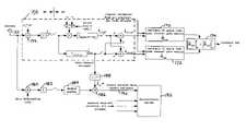
- FIG. 1is a high-level block diagram illustrating a wireless communication system according to a preferred embodiment of the present invention.
- FIG. 2is a flow diagram illustrating a general overview of transmitter-side processing according to a preferred embodiment of the present invention.
- FIG. 3illustrates a timeline for performing the signal processing according to a representative embodiment of the present invention.
- FIG. 4is a more detailed flow diagram illustrating transmitter-side processing according to a preferred embodiment of the present invention.
- FIG. 5is a block diagram showing receiver processing according to a representative embodiment of the present invention.
- CDMA code division multiple access DS-CDMAdirect sequence CDMA forward link radio link from the transmitting base station to the receiving mobile station HW hardware, referring to the fixed digital logic portion of a modem as opposed to SW MIMO multiple input multiple output MS mobile station; typically, a user of a cellular wireless network, e.g., a cell phone or a wireless data terminal pilot a known signal or “training sequence” transmitted so that the receiver may use it to estimate the channel response.
- receive unitthe unit that is receiving the signals that are sent according to the transmit weight adaptation algorithm, generally referred to as the mobile station.
- This unitis also actively transmitting, as, at a minimum, the feedback information must be transmitted to the “transmit” unit, and usually there is other reverse traffic and signaling.
- reverse link radio link from the transmitting mobile station to the receiving base station Rxreceive SISO single-input single-output STC space time coding SW software, typically to distinguish the (modifiable) SW portion of a modem from the HW transmit unit the unit that is transmitting the signals that are sent according to the transmit weight adaptation algorithm, generally referred to as the base station.
- This unitis also actively receiving, as at a minimum the feedback infor- mation must be received from the “receive” unit, and usually there is other reverse traffic and signaling.
- Txtransmit ⁇ . ⁇ matrix or vector norm, typically 2-norm if not otherwise specified.
- the 2-normis ⁇ x ⁇ 2 ⁇ ⁇ square root over (x H x) ⁇ .
- Fr matrix or vector Frobenius normtypically 2-norm if not otherwise specified.
- the Frobenius normis ⁇ A ⁇ Fr ⁇ ⁇ i , j ⁇ ⁇ ⁇ a i , j ⁇ 2
- the present inventionallows for an increase of the transmission capacity of a digital wireless network, increasing the data rates which can be transmitted across the channel.
- the inventionprovides a specific technique of “multi-mode tracking” (frequently called “subspace tracking”), tracking the independent modes of the MIMO transfer function.
- the specific algorithm presentedis a multi-mode variation of the algorithm originally disclosed in the '081 Application. All of the additions and variations on that disclosure described in the '925, '751 and '728 Applications can in principle be applied to this invention.
- the STC algorithmsuse the independent modes of the MIMO transfer function to effectively attain multiple parallel data pipes. For example, with N T transmit and N R receive antennas, there can in general be min(N T , N R ) independent modes (separable channels) from the transmitting system to the receiving system, which allows for a factor of min(N T , N R ) increase in the effective available transmission bandwidth. This allows for greater transmission bit rates.
- the optimal transmission algorithmuses a “water filling” power/rate allocation strategy into these non-zero modes, but the complexity of this is prohibitive. Only the receiving unit can measure the channel, and therefore feedback is required to give this information to the transmitting unit.
- the present inventiondefines an algorithm for tracking the non-zero modes of the transfer function utilizing feedback, but without the additional complexity of doing the optimal power/rate allocation into those modes. This can provide benefit when the number of transmit antennas exceeds the number of receive antennas.
- the specific algorithm proposedis a multi-mode variation on the algorithm originally disclosed in the '081 Application. It should be pointed out that the algorithm of the '081 Application is in some sense a subset of the algorithm described in the present invention, where the number of receive antennas is one, and hence the number of tracked modes is one.
- FIG. 1illustrates a high-level block diagram of a system 10 according to the present invention.
- a stream of digital traffic signal data 12is processed 14 to perform space-time coding, channel interleaving and demultiplexing, resulting in N STC separate data channels.
- Antenna weightsare then applied 16 to convert these N STC channels (channel multiplexed together with N STC pilot signals, described in more detail below) into N T signals.
- These N T signalsare provided to the corresponding N T transmit antennas in antenna array 18 .
- N R antennas 20receive N R corresponding signals. From these N R signals, each including N STC pilot signals, the N STC data signals are decoded and a feedback signal is generated 22 , the feedback signal indicating how the transmitter should modify the transmit antenna weights in order to appropriately track the N STC transmit modes. This feedback signal is then transmitted to receive antenna 24 (on the transmitter side) and is in fact used to modify 26 the antenna wights for use in the next transmit interval. As a result of this arrangement, multiple independent modes between a single transmitter and a single receiver can be tracked and used to simultaneously transmit multiple data signals. The foregoing processing is described in more detail below.
- the focus of this inventionis the signal processing approach to tracking the transfer function modes, and not the coding techniques applied once those modes are determined. Any of a number of standard coding techniques can be applied in this situation, as the MIMO transfer function modes can be utilized the same as any time/frequency modes are used for coding. There is a substantial body of existing prior art on the subject of signal processing approaches for adaptation in non-MIMO environments, both academic and industrial.
- Clog 2 ⁇ ( 1 + ⁇ h ⁇ ⁇ 2 ⁇ P ( T ) 2 ⁇ ⁇ ⁇ 2 ) Eq . ⁇ 2 where the units of C are bits per channel use.
- the channel inputis a N T ⁇ 1 vector x
- the outputis the N R ⁇ 1 vector y
- the channel gainis a N R ⁇ N T matrix H
- the noiseis a zero mean N R ⁇ 1 complex Gaussian vector n with correlation 2 ⁇ 2 I.
- the choice of the nature of xnow becomes important.
- the transmit power constraint P (T)is maintained. If the transmitter has knowledge of the value of H, then this can be used to advantage. If this is not known (“blind” space-time coding), then the optimum strategy is to transmit x as a zero mean uncorrelated Gaussian vector, and it is straightforward to show that:
- C blindlog 2 ⁇ ( ⁇ I + P ( T ) 2 ⁇ N T ⁇ ⁇ ⁇ 2 ⁇ H H ⁇ H ⁇ ) Eq . ⁇ 4
- the problemhas a matrix rank given by N min .
- An “informed” transmitterwhich knows the realization of H, can attain better performance than that described above.
- the optimal systemwould use “water filling” in each of the eigenmodes. This technique allocates the transmit power to each of the modes according to the gain of that mode (given by ⁇ k ), with larger transmitted power and higher data rates for the modes with higher gains. Those modes with zero gain receive zero power, since no power transmitted into those modes will reach the receiver.
- the term ( ⁇ k >0)represents the numerical value of the Boolean, 0 if not true, and 1 if true.
- C mode ⁇ ⁇ trackinglog 2 ⁇ ( ⁇ 1 + P ( T ) 2 ⁇ N R ⁇ ⁇ ⁇ 2 ⁇ H H ⁇ H ⁇ ) Eq . ⁇ 13
- N R modesare non-zero, and transmit into that many modes according to some multi-mode tracking algorithm which would attempt to track those N R modes. Note that this technique only provides improvement if the number of transmit antennas exceeds the number of receive antennas. This situation is deemed to be reasonable since it can be desirable, both from size and cost constraints, to place more antennas on the network infrastructure than on the mobile terminals.
- F pre (.) pre-measurement functionperforming some degree of orthonormalization, returning a matrix of same dimension as the input.
- This functioncan be different for different implementations.
- F post (.) post-feedback functionperforming some degree of orthonormalization, returning a matrix of same dimension as the input. This should “complete” any orthonormalization left incomplete by F pre N col (.) column normalization function, returning column-normalized modification of input matrix; see equation Eq. 14.
- Q(.) functionreturning orthonormal basis column vectors of the input matrix column vectors, i.e., the matrix Q of a QR decomposition.
- An exampleis the orthonormal basis set arising from Gramm-Schmidt orthogonalization.
- N Tnumber of transmit antennas
- N Rnumber of receive antennas
- N STC number of space-time coding transmission modesi.e., the number of coded parallel transmissions M slot duration of the pilot even/odd banking slot, units are in increments of i M meas number of slots between measurement and weight updates t(i) N T ⁇ 1 transmitted vector r(i) N R ⁇ 1 received vector s traffic (i) N STC ⁇ 1 vector of the channel-coded symbols, transmitted at time i s pilot (i) N STC ⁇ 1 vector of the dedicated pilot signal, transmitted at time i P (T) traffic total mean transmitted power of the traffic channel (summed over all antennas) P (T) pilot total mean transmitted power of pilot channel (summed over all antennas) H(i) N R ⁇ N T matrix, specifying the forward channel complex gain from each Tx antenna to each Rx antenna W base (i) N T T
- W traffic(i) N T ⁇ N STC vector, antenna complex weights for data channel W pilot (i) N T ⁇ N STC vector, antenna complex weights for pilot channel.
- thisis instantaneously equal to either W even (i) or W odd (i).
- the column normalization function on a matrix Ais introduced as F( ).
- N col ( A n ⁇ m )[ a 0 ⁇ a 0 ⁇ ⁇ a 1 ⁇ a 1 ⁇ ⁇ ⁇ ... ⁇ ⁇ a m - 1 ⁇ a m - 1 ⁇ ] Eq . ⁇ 14
- the channel gainis a matrix H rather than a vector c, and is portrayed as transposed from the previous use of c. Many of the matrices and vectors have their element dimension explicitly included in the presentation for additional clarity. This is displayed below the matrix, number of rows followed by number of columns.
- “Orthogonal matrix”describes a matrix with mutually orthogonal and unit 2-norm columns, although the term “unitary matrix” is often used when such a matrix is complex (as is the case here).
- the system describedwill show signals and operation for transmission to one receive unit (with multiple antennas). Several such processes, to several receivers, generally will be occurring simultaneously.
- the algorithmwill attempt to track the weights so that the column span of W is the same as the row span of H, which means that W occupies the sub-space defined by the nonzero eigenmodes described in section 3.
- the weights applied to the various antennasto be orthonormal (e.g., Eq. 15) we are assured that the transmitter is transmitting equal power into all of the modes of the column span of W; this condition must be met by at least W base , and approximately met by the other weight matrices.
- the eigenvalues of Rare nearly equal to each other, then orthogonal transmission will approximately provide orthogonal reception, which simplifies the receiver.
- the transmissioncan then be described as:
- the desired property of the antenna weights for multi-mode trackingis:
- Eq. 20The condition of Eq. 20 is attained by maximizing the total received power, subject to the orthogonal transmission constraint of Eq. 15. That is, any algorithm should use the pilot channel (although algorithms could be developed to also, or instead, use the traffic channel) to attempt to find:
- This individual mode trackingprovides orthogonality at the receiver; that is, each code stream of s traffic is received across the antennas orthogonal to all other code streams, making receiver processing easier.
- the orthogonality of the received code streamsis seen in Eq. 24, where the tilde represents the same permutation pattern as in Eq. 22.
- the gradient algorithm describedhas the property that the resultant weight vectors tend towards the individual eigenvectors automatically, because the earlier weight vectors are given more full freedom than the later weight vectors and the dominant eigenmodes track faster; as a result, the weight vectors tend towards the dominance-ordered eigenvectors.
- the receivercan ignore this in the processing or do equalization, analogous to time-series equalization in modems with intersymbol interference.
- the non-orthogonality discussed hereis essentially intersymbol interference, so those algorithms apply directly with the exception of those that take advantage of time series specific properties (i.e., successful vector inputs are not independent, but rather are “shifted” in a time series).
- the transmitting unittransmits the multiple pilots (one for each space-time code stream) with even and odd time multiplexed weight vectors, modified from the “base” tracked weight vectors by a scaled perturbation vector; the receiving unit selects which of these perturbed pilot weight sets maximizes Eq. 21 and generates feedback indicating this; the transmitter updates the weights based on this feedback, using a technique (such as a QR style orthogonalization) to maintain the condition of Eq. 15.
- a techniquesuch as a QR style orthogonalization
- the even and odd weight vector setscan be selected in many ways. The anticipated and preferred generation of these weights is by perturbation. Each individual weight vector is applied to one space-time coding stream of s traffic , and each is individually normalized so that each space-time coding stream is transmitted with equal power.
- This “expectation”can be a statistical expectation if the perturbations are generated randomly (or pseudo-randomly), or it can be the long-term average if they are generated in some clearly deterministic manner. This power constraint allows the adaptation rate to be captured in the algorithm parameters ⁇ 1 and ⁇ 2 .
- the use of the normalized mean of the even and odd pilot weight vectors as the traffic weight vector (Eq. 26)allows the receiver to recover the composite channel of each of the N STC code streams in a simple manner as the received mean of the pilot composite channel over both the even and odd time slots.
- the pre-measurement function F pre ( )be the weight vector normalization function N col ( ) so that the total transmission power is unchanged and feedback selection by the receiver is based on occupied subspace rather than transmission power, but it not an invention requirement (for reasons of computational complexity, one may decide to remove this normalization).
- F pre ( )is set to be the orthonormalization of the input, Q( ), so that each tested weight set is in fact an orthonormal set; this is not necessarily desirable because by removing this constraint on the test perturbation, we generally can attain better modal separation, like what is described in section 4.2.1 above.
- the receivercalculates which time slot, even or odd, gave the larger total received power.
- a feedback bitis transmitted from this receive unit to the transmit unit indicating which time slot gave the larger received power.
- the transmit unitupdates the base weight vector matrix W base to be the selected even or odd matrix, or the matrix that arises by rescaling the perturbation P by ⁇ 2 , as this allows an extra degree of freedom in determining the measurement perturbation size by ⁇ 1 and the step update perturbation by ⁇ 2 .
- This matrixundergoes the orthonormalization Q( ) if it was not fully performed in the even/odd probing itself.
- the preferred orthonormalization routineis Gramm-Schmidt, although other techniques may be used.
- the set of perturbation vectors Pcan be generated in different ways. The most straightforward is simply that each element of P is generated as an independent complex Gaussian random variable of two-dimensional variance two (i.e., unit variance in each dimension). Some other techniques were discussed in the '081 Application, including selecting each element from the set ⁇ 1, ⁇ j ⁇ .
- transmissionis begun in step 102 .
- a base set of transmission weight vectorsare generated. These weight vectors are orthonormal and may be generated arbitrarily or, alternatively, may be generated in a manner so as to approximate the best N STC transmission modes, e.g., by using the codebook multi-mode technique described in section 4.4 below.
- a new perturbation matrixis generated 108 .
- the generation of the perturbation matrixpreferably is based on the current base weight vectors, i.e., such that the perturbation matrix occupies only the null space of the weighting matrix. Otherwise, the perturbation matrix may be pseudo-random.
- step 110new even pilot, odd pilot and traffic signal weights are generated based on the perturbation matrix, as set forth in Eqs. 26-28.
- F preis set to N col .
- step 112the calculated weight vectors are applied to their corresponding signals.
- step 122a determination is made as to whether the feedback bit indicates if the even or odd pilot signal channel resulted in the larger received power. If the even channel resulted in the larger power, processing proceeds to step 124 . Otherwise, processing proceeds to step 126 .
- step 124a scaled version of the perturbation matrix is added to the base weighting matrix and orthonormalization is performed.
- step 126a scaled version of the perturbation matrix is subtracted from the base weighting matrix and orthonormalization is performed.
- step 128the weight vectors are recomputed in the same manner described above in connection with step 110 .
- FIG. 5illustrates a block diagram showing receiver processing according to a preferred embodiment of the invention.
- a path 150is provided for each combination of receive antenna 152 (denoted with subscript k) and each data stream (denoted with subscript j).
- the data stream jis demultiplexed 154 and then an estimate ( ⁇ circumflex over ( ⁇ ) ⁇ j,k ) of the STC-to-receive-antenna channel gain ( ⁇ j,k ) is generated, as well as the separate even and odd estimates. In the present embodiment, this is accomplished using the particular combination of accumulators, adders and multiplier shown in FIG. 5 .
- the separate even and odd estimatesare combined across all antennas k and all data streams j to provide an estimate of the even and odd space-time code channel gain matrices, in elements 170 and 172 , respectively.
- the squared norms of the even and odd matricesare taken and compared, and the feedback bit is generated to indicate the larger to the two.
- the signal received at antenna 152is depsread using multiplier 180 and accumulator 182 , deskewed 184 , and multiplied 186 by the complex conjugate 188 of the estimate of the STC-to-receive-antenna channel gain ⁇ circumflex over ( ⁇ ) ⁇ j,k , so as to obtain a singe-antenna estimate 190 of the data symbols for a single data stream.
- symbol estimatesare combined across all receive antennas, and deinterleaving and decoding are performed.
- the weight vectors for the dedicated pilot signalare constant during a measurement interval (in contrast to the even/odd multiplexing of the gradient algorithm).
- the perturbation gradient approach to this problemis deemed preferable to the codebook selection feedback.
- the implementation at the receiveris simpler, because the algorithm computes 2 ⁇ N R ⁇ N STC measurements and two decision metrics are made to compare even/odd time slots.
- the codebook selectionrequires N R ⁇ N T raw measurements, plus generation of many metrics (6 metrics for w 4,2,6 ).
- the gradient algorithmrequires the receiver to have knowledge of the number of space-time coded streams and each of the corresponding pilot signals, while the code book selection requires the receiver to have knowledge of the number of coded streams, each corresponding pilot signal, plus the number of transmit antennas and a pilot for each antenna.
- the complexity of the interoperabilityis much greater and the flexibility of the network is reduced for codebook selection relative to perturbation gradient.
- a general-purpose computer for implementing techniques of the present inventiontypically will include, for example, at least some of the following components: one or more central processing units (CPUs), read-only memory (ROM), random access memory (RAM), input/output circuitry for interfacing with other devices and for connecting to one or more networks (which in turn may connect to the Internet or to any other networks), a display (such as a cathode ray tube or liquid crystal display), other output devices (such as a speaker or printer), one or more input devices (such as a mouse or other pointing device, keyboard, microphone or scanner), a mass storage unit (such as a hard disk drive), a real-time clock, a removable storage read/write device (such as for reading from and/or writing to a magnetic disk, a magnetic tape, an optomagnetic disk, an optical disk, or the like), and a modem (which also may connect to the Internet or to any other computer network via a dial-up connection).
- CPUscentral processing units
- ROMread-only memory
- RAMrandom
- Suitable hardware for use in implementing the present inventionmay be obtained from various vendors. Various types of hardware may be used depending upon the size and complexity of the tasks. Suitable general-purpose computers include mainframe computers, multiprocessor computers, workstations, personal computers, and even smaller computers such as PDAs, wireless telephones or any other networked appliance or device.
- the present inventionalso relates to machine-readable media on which are stored program instructions for performing the methods of this invention.
- Such mediainclude, by way of example, magnetic disks, magnetic tape, optically readable media such as CD ROMs and DVD ROMs, semiconductor memory such as PCMCIA cards, etc.
- the mediummay take the form of a portable item such as a small disk, diskette, cassette, etc., or it may take the form of a relatively larger or immobile item such as a hard disk drive, ROM or RAM provided in a computer.
- the descriptions of the above embodimentsrefer to a transmitter and receiver, reflecting the flow of data for the traffic channel of interest in the implementation of present invention.
- the “transmitter”will also receive data and the “receiver” will also transmit data, both in connection with the transmission of feedback data and, typically, in connection with one or more reverse traffic channels.
- functionalitymay be ascribed to a particular module or component. However, unless any particular functionality is described above as being critical to the referenced module or component, functionality may be redistributed as desired among any different modules or components, in some cases completely obviating the need for a particular component or module and/or requiring the addition of new components or modules.
- the precise distribution of functionalitypreferably is made according to known engineering tradeoffs, with reference to the specific embodiment of the invention, as will be understood by those skilled in the art.
Landscapes
- Engineering & Computer Science (AREA)
- Computer Networks & Wireless Communication (AREA)
- Signal Processing (AREA)
- Power Engineering (AREA)
- Physics & Mathematics (AREA)
- Mathematical Physics (AREA)
- Mobile Radio Communication Systems (AREA)
Abstract
Description
| AA | adaptive antenna, more generally adaptive antenna |
| algorithm | |
| BS | base station, fixed station that communicates with multiple |
| mobile stations and providing their gateway to the fixed | |
| network. | |
| CDMA | code division multiple access |
| DS-CDMA | direct sequence CDMA |
| forward link | radio link from the transmitting base station to the receiving |
| mobile station | |
| HW | hardware, referring to the fixed digital logic portion of a |
| modem as opposed to SW | |
| MIMO | multiple input multiple output |
| MS | mobile station; typically, a user of a cellular wireless |
| network, e.g., a cell phone or a wireless data terminal | |
| pilot | a known signal or “training sequence” transmitted so that |
| the receiver may use it to estimate the channel response. | |
| receive unit | the unit that is receiving the signals that are sent according |
| to the transmit weight adaptation algorithm, generally | |
| referred to as the mobile station. This unit is also actively | |
| transmitting, as, at a minimum, the feedback information | |
| must be transmitted to the “transmit” unit, and usually there | |
| is other reverse traffic and signaling. | |
| reverse link | radio link from the transmitting mobile station to the |
| receiving base station | |
| Rx | receive |
| SISO | single-input single-output |
| STC | space time coding |
| SW | software, typically to distinguish the (modifiable) SW |
| portion of a modem from the HW | |
| transmit unit | the unit that is transmitting the signals that are sent |
| according to the transmit weight adaptation algorithm, | |
| generally referred to as the base station. This unit is also | |
| actively receiving, as at a minimum the feedback infor- | |
| mation must be received from the “receive” unit, and | |
| usually there is other reverse traffic and signaling. | |
| Tx | transmit |
| ∥.∥ | matrix or vector norm, typically 2-norm if not otherwise |
| specified. For a vector x, the 2-norm is ∥x∥2≡ {square root over (xHx)}. For a | |
| matrix A, the two norm is | |
| ∥.∥Fr | matrix or vector Frobenius norm, typically 2-norm if not |
| otherwise specified. For a matrix A, the Frobenius norm is | |
| |.| | scalar absolute value or matrix determinant |
| (.)H | matrix or vector hermitian (complex conjugate transpose) |
2. Introduction
y=hx+n Eq. 1
where x is the input modulation sequence, h is the complex gain of the channel, n is a zero mean complex Gaussian random variable with variance 2σ2, and y is the sequence received by the receiver. Time indices are omitted, and capacity is considered in terms of bits per ues of the channel, that is the average number of information bits received and correctly decoded at the receiver for each realization of Eq. 1. This capacity is found with the mean power of x constrained to some transmit power P(T). Then the capacity, C, is given by:
where the units of C are bits per channel use.
y=Hx+n Eq. 3
The choice of the nature of x now becomes important. The transmit power constraint P(T)is maintained. If the transmitter has knowledge of the value of H, then this can be used to advantage. If this is not known (“blind” space-time coding), then the optimum strategy is to transmit x as a zero mean uncorrelated Gaussian vector, and it is straightforward to show that:
where |·| denotes the matrix determinant and ( )Hdenotes the hermitian transpose (or conjugate transpose).
UHU=I Eq. 6
VHV=I Eq. 7
Then the channel formulation of Eq. 3 can be recast into an equivalent format with {tilde over (y)}, {tilde over (x)} and ñ.
Because V is an orthogonal matrix and x is uncorrelated, {tilde over (x)} has the same statistics as x,
The same applies to the Gaussian noise term n.
Let the NT×NTsquared gain matrix be R
R≡HHH Eq. 10
and the eigendecomposition of R be given by:
R≡VΛVH Eq. 11
where the orthogonal matrix V is comprised of the eigenvectors of R and the NT×NTdiagonal matrix Λ is ΛH/2Λ1/2, comprising of the eigenvalues λkof R. Then, the independent components of Eq. 8 are seen to correspond to the eigenmodes of R, or the independent modes of the channel. These are the parallel “channels” which are made available through the space-time coding techniques in the MIMO environment and which allow for capacity increases over non-MIMO systems.
Here, the term (λk>0) represents the numerical value of the Boolean, 0 if not true, and 1 if true. Using this correlation matrix on x, the transmitter transmits power only into those modes which have a non-zero gain to the receiver, and hence which deliver usable power to the receiver.
Hence, we find that when the number of receive antennas is less than the number of transmit antennas, we can obtain a capacity improvement of NT/NRfrom this multi-mode tracking implementation. One object of the present invention is a specific algorithm to accomplish this multi-mode tracking. In practice, one implementation would be to assume that NRmodes are non-zero, and transmit into that many modes according to some multi-mode tracking algorithm which would attempt to track those NRmodes. Note that this technique only provides improvement if the number of transmit antennas exceeds the number of receive antennas. This situation is deemed to be reasonable since it can be desirable, both from size and cost constraints, to place more antennas on the network infrastructure than on the mobile terminals.
| Fpre(.) | pre-measurement function, performing some degree of |
| orthonormalization, returning a matrix of same dimension as | |
| the input. This function can be different for different | |
| implementations. | |
| Fpost(.) | post-feedback function, performing some degree of |
| orthonormalization, returning a matrix of same dimension | |
| as the input. This should “complete” any | |
| orthonormalization left incomplete by Fpre | |
| Ncol(.) | column normalization function, returning column-normalized |
| modification of input matrix; see equation Eq. 14. | |
| Q(.) | function returning orthonormal basis column vectors of the |
| input matrix column vectors, i.e., the matrix Q of a QR | |
| decomposition. An example is the orthonormal basis set | |
| arising from Gramm-Schmidt orthogonalization. | |
| i | time index, at the Nyquist rate |
| NT | number of transmit antennas (NT> NR) |
| NR | number of receive antennas (NT> NR) |
| NSTC | number of space-time coding transmission modes, i.e., the |
| number of coded parallel transmissions | |
| Mslot | duration of the pilot even/odd banking slot, units are in |
| increments of i | |
| Mmeas | number of slots between measurement and weight updates |
| t(i) | NT× 1 transmitted vector |
| r(i) | NR× 1 received vector |
| straffic(i) | NSTC× 1 vector of the channel-coded symbols, transmitted |
| at time i | |
| spilot(i) | NSTC× 1 vector of the dedicated pilot signal, transmitted at |
| time i | |
| P(T)traffic | total mean transmitted power of the traffic channel |
| (summed over all antennas) | |
| P(T)pilot | total mean transmitted power of pilot channel (summed over |
| all antennas) | |
| H(i) | NR× NTmatrix, specifying the forward channel complex |
| gain from each Tx antenna to each Rx antenna | |
| Wbase(i) | NT× NSTCvector, “base” tracked antenna complex weights |
| from which all other weights are calculated in the | |
| perturbation gradient tracking approach. | |
| Wtraffic(i) | NT× NSTCvector, antenna complex weights for data channel |
| Wpilot(i) | NT× NSTCvector, antenna complex weights for pilot channel. |
| In the gradient operation, this is instantaneously equal to | |
| either Weven(i) or Wodd(i). | |
| Weven(i) | NT× NSTCvector, antenna complex weights, even pilot |
| channel | |
| Wodd(i) | NT× NSTCvector, antenna complex weights, odd pilot channel |
| P(i) | NT× NSTC, test perturbation to the complex weights, |
| preferably generated as a complex Gaussian | |
| β | algorithm parameter, adaptation rate |
Note that the nomenclature varies somewhat from the nomenclature of the previous related disclosures incorporated by reference herein. The channel gain is a matrix H rather than a vector c, and is portrayed as transposed from the previous use of c. Many of the matrices and vectors have their element dimension explicitly included in the presentation for additional clarity. This is displayed below the matrix, number of rows followed by number of columns. “Orthogonal matrix” describes a matrix with mutually orthogonal and unit 2-norm columns, although the term “unitary matrix” is often used when such a matrix is complex (as is the case here).
- orthonormal transmission weights.
- channel-coded symbols are uncorrelated (this arises from coding theory, and is essentially true of all codes with random information input) with total mean power of unity
- pilot symbols are uncorrelated (in order for them to be separable at the receiver) with unit total mean power, as generally will be attained by application of orthogonal or quasi-orthogonal pilot channelization, with distinct pilot channels on each transmit antenna.
The received vector is then:
where {tilde over (H)} represents the composite channel as seen by the receiver. This is the channel that the receiver can measure, as it has no direct means of separating the contributions of the physical channel and the applied weights.
Recalling that the eigenvectors and eigenvalues of Eq. 5 and Eq. 11 were sorted according to magnitude, Eq. 20 says that only those modes with the maximum gains are transmitted into by this set of weight vectors, because the (NT−NSTC)×NTzero matrix indicates no response in the eigenspaces with minimum gain. This guarantees that all of the transmitted power will reach the receiver.
So, the algorithm operates the maximize tr({tilde over (H)}pilotH{tilde over (H)}pilot)=∥{tilde over (H)}pilot∥Fr, where {tilde over (H)}pilotis the channel gain matrix measured by the receiver, specifying the gain of each space time code stream to each receive unit antenna.
- Step70: define the number of space time channels to be exercised, NSTC, with NSTC≦NR(where NT>NSTC), through negotiation between the transmit and receive units. Measurements at the receive unit may be used if there is a reasonable probability of having the number of useful modes be less than the number of receive antennas. Otherwise, NSTCcan be simply set to NR.
- Step72: generate orthonormal multi-antenna weight vectors W, which translate the NSTCcode streams to NTantenna transmissions.
- Step74: track the weight vectors W through a mode-tracking algorithm, incorporating feedback from the mobile unit, in an attempt to track towards the condition described in Eq. 20, which maximizes Eq. 21 subject to Eq. 15.
where vkand wkare the columns of V and W respectively, and the tilde ‘{tilde over ( )}’ simply denotes some arbitrary reordering of the columns of W; that is, it is desirable that the inner product of any of the weight vectors is zero with all but one of the eigenvectors. Given that V and W are both orthonormal, this means that W is V with appropriately reordered columns. That is, from Eq. 22:
Weven=Fpre(Wbase+β1P) Eq. 27
Wodd=Fpre(Wbase−β1P) Eq. 28
E(pkHpk)=NTk=0:NSTC−1 Eq. 29
This “expectation” can be a statistical expectation if the perturbations are generated randomly (or pseudo-randomly), or it can be the long-term average if they are generated in some clearly deterministic manner. This power constraint allows the adaptation rate to be captured in the algorithm parameters β1and β2.
- 1. Negotiating (between transmit unit and receive unit) the number of active STC modes which will be used, NSTC. This should conform to NSTC≦min(NT, NR), and must conform to NSTC≦NT.
- 2. Determining through channel measurements at the receiver the number of active modes, which may be less than min(NT, NR), to use for NSTC.
- 3. Mode tracking in a space-time coding algorithm where the number of transmit antennas is greater than the number of receive antennas. That is, the concept of mode tracking itself is believed to be new.
- 4. STC mode tracking using receive-unit to transmit-unit feedback.
- 5. A mode tracking algorithm using the stochastic gradient techniques previously developed for multiple-input single-output (MISO) systems in the '081, '925, '751 and '728 Applications. Specifically, the perturbation probing (especially where the data transmit weight is the mean of the perturbed weights to allow easy channel recovery) and feedback mechanism which requires interoperability between the receive unit and the transmit unit.
7. Possible Modifications to the Invention- The channel coding scheme is not specified above. While the coding scheme is important, the present invention is directed to a signal-processing algorithm that generally can be executed independently of the coding scheme used. Possible coding schemes include convolutional or Turbo coding. For data applications, high-performance, large-block-length codes like Turbo codes generally will be more preferable.
- Channel interleaving is part of the channel coding, and again is not specified above and generally is not directly relevant to the techniques of the present invention.
- The decoding scheme is not specified. This can be performed in many ways, and generally is somewhat independent from the tracking signal-processing algorithm described.
- Other specific mode-tracking algorithms could be implemented. Variations on existing MISO feedback approaches could be done for the MIMO case.
- Different “startup” algorithms could be run for fast convergence, where the initial even/odd weight matrix of the perturbation stochastic gradient algorithm is generated in some manner other than perturbation to allow fast convergence. In the steady state, the perturbation approach is believed to give better performance, based on simulation results for the single-mode algorithm of the '081 Application. This variation applies equally to the previously described algorithms of the '081, '925, '751 and '728 Applications.
8. System Environment
Claims (24)
Priority Applications (1)
| Application Number | Priority Date | Filing Date | Title |
|---|---|---|---|
| US10/198,303US7248638B1 (en) | 2001-03-23 | 2002-07-17 | Transmit antenna multi-mode tracking |
Applications Claiming Priority (8)
| Application Number | Priority Date | Filing Date | Title |
|---|---|---|---|
| US27850101P | 2001-03-23 | 2001-03-23 | |
| US30847401P | 2001-07-27 | 2001-07-27 | |
| US34613001P | 2001-10-29 | 2001-10-29 | |
| US10/076,925US7180956B1 (en) | 2000-08-02 | 2002-02-14 | Method and apparatus for applying overlaid perturbation vectors for gradient feedback transmit antenna array adaptation |
| US10/080,751US7433416B1 (en) | 2000-08-02 | 2002-02-22 | Method and apparatus for generating transmit adaptive antenna weights with nulling using binary gradient feedback |
| US10/080,728US7236538B1 (en) | 2000-08-02 | 2002-02-22 | Method and apparatus for improving transmit antenna weight tracking using channel correlations in a wireless communication system |
| US10/197,965US7224758B1 (en) | 2001-03-23 | 2002-07-16 | Multiple transmit antenna weighting techniques |
| US10/198,303US7248638B1 (en) | 2001-03-23 | 2002-07-17 | Transmit antenna multi-mode tracking |
Related Parent Applications (1)
| Application Number | Title | Priority Date | Filing Date |
|---|---|---|---|
| US10/197,965Continuation-In-PartUS7224758B1 (en) | 2001-03-23 | 2002-07-16 | Multiple transmit antenna weighting techniques |
Publications (1)
| Publication Number | Publication Date |
|---|---|
| US7248638B1true US7248638B1 (en) | 2007-07-24 |
Family
ID=38266904
Family Applications (1)
| Application Number | Title | Priority Date | Filing Date |
|---|---|---|---|
| US10/198,303Expired - Fee RelatedUS7248638B1 (en) | 2001-03-23 | 2002-07-17 | Transmit antenna multi-mode tracking |
Country Status (1)
| Country | Link |
|---|---|
| US (1) | US7248638B1 (en) |
Cited By (43)
| Publication number | Priority date | Publication date | Assignee | Title |
|---|---|---|---|---|
| US20040224725A1 (en)* | 2003-02-17 | 2004-11-11 | Samsung Electronics Co., Ltd. | Wireless communication system and method using multiple antennas |
| US20050169396A1 (en)* | 2002-05-27 | 2005-08-04 | Paul-Walter Baier | Method for transmitting information in a mimo radio communication system and radio communication system |
| US20060018403A1 (en)* | 2004-07-26 | 2006-01-26 | Nec Laboratories America, Inc. | Optimized high rate space-time codes for wireless communication |
| US20060039328A1 (en)* | 2004-08-17 | 2006-02-23 | Lg Electronics Inc. | Data communication in a wireless communication system using space-time coding |
| US20060039493A1 (en)* | 2004-08-19 | 2006-02-23 | Nokia Corporation | Generalized m-rank beamformers for mimo systems using successive quantization |
| US20060050811A1 (en)* | 2004-09-06 | 2006-03-09 | Ntt Docomo, Inc | Shared frequency transmitter |
| US20060067277A1 (en)* | 2004-09-30 | 2006-03-30 | Thomas Timothy A | Method and apparatus for MIMO transmission optimized for successive cancellation receivers |
| US20060140294A1 (en)* | 2004-11-05 | 2006-06-29 | Nokia Corporation | Block modulation |
| US20060252386A1 (en)* | 2003-06-30 | 2006-11-09 | Jan Boer | Methods and apparatus for backwards compatible communication in a multiple input multiple output communication system with lower order receivers |
| US20070086536A1 (en)* | 2002-10-25 | 2007-04-19 | Qualcomm, Incorporated | Channel estimation and spatial processing for tdd mimo systems |
| US20070149180A1 (en)* | 2005-12-05 | 2007-06-28 | Lin Xintian E | Multiple input, multiple output wireless communication system, associated methods and data structures |
| US20080008276A1 (en)* | 2005-03-15 | 2008-01-10 | Hitoshi Yokoyama | Communication device and communication method |
| US20080123602A1 (en)* | 2005-06-15 | 2008-05-29 | Huawei Technologies Co., Ltd. | Method and system for channel quality estimation |
| US20080212700A1 (en)* | 2006-12-29 | 2008-09-04 | Samsung Electronics Co., Ltd. | Method and apparatus for transmitting and receiving control channel message in a mimo mobile communication system |
| US20080285666A1 (en)* | 2006-12-14 | 2008-11-20 | Xiaodong Wang | Methods and Systems for Digital Wireless Communication |
| US20080285665A1 (en)* | 2006-12-14 | 2008-11-20 | Xiaodong Wang | Methods and Systems for Providing Feedback for Beamforming |
| US20090016463A1 (en)* | 2006-04-06 | 2009-01-15 | Dong Wook Roh | Method for transmitting channel state information in multiple antenna system |
| US20100020891A1 (en)* | 2008-07-23 | 2010-01-28 | Sony Corporation | Wireless communication system, wireless communication apparatus and wireless communication method, encoding apparatus and encoding method, and computer program |
| US20100111211A1 (en)* | 2005-05-30 | 2010-05-06 | Jin-Kyu Han | Apparatus and method for transmitting/receiving data in a mobile communication system using multiple antennas |
| US20100118784A1 (en)* | 2007-04-30 | 2010-05-13 | Göransson Bo | Recommending a Transmission Mode for a MIMO-Supporting UE |
| US20100330928A1 (en)* | 2009-06-29 | 2010-12-30 | Nec Laboratories America, Inc. | Fast convergence to optimal beam patterns |
| US20110069774A1 (en)* | 2007-06-19 | 2011-03-24 | Xiaodong Wang | Methods and Systems for Providing Feedback for Beamforming and Power Control |
| US20110105032A1 (en)* | 2008-07-16 | 2011-05-05 | Nec Corporation | Control method of wireless communication system, wireless communication system, transmitting apparatus, and receiving apparatus |
| US7986742B2 (en) | 2002-10-25 | 2011-07-26 | Qualcomm Incorporated | Pilots for MIMO communication system |
| US20110194649A1 (en)* | 2006-02-14 | 2011-08-11 | Nec Laboratories America, Inc. | Method of Precoding with a Codebook for a Wireless System With Multiple Transmission Ranks and a Quantized Beamforming Matrix |
| US8116260B1 (en)* | 2001-08-22 | 2012-02-14 | At&T Intellectual Property Ii, L.P. | Simulcasting MIMO communication system |
| US8134976B2 (en) | 2002-10-25 | 2012-03-13 | Qualcomm Incorporated | Channel calibration for a time division duplexed communication system |
| US8145179B2 (en) | 2002-10-25 | 2012-03-27 | Qualcomm Incorporated | Data detection and demodulation for wireless communication systems |
| US8169944B2 (en) | 2002-10-25 | 2012-05-01 | Qualcomm Incorporated | Random access for wireless multiple-access communication systems |
| US8194770B2 (en) | 2002-08-27 | 2012-06-05 | Qualcomm Incorporated | Coded MIMO systems with selective channel inversion applied per eigenmode |
| US8203978B2 (en) | 2002-10-25 | 2012-06-19 | Qualcomm Incorporated | Multi-mode terminal in a wireless MIMO system |
| US8208364B2 (en) | 2002-10-25 | 2012-06-26 | Qualcomm Incorporated | MIMO system with multiple spatial multiplexing modes |
| US8218609B2 (en) | 2002-10-25 | 2012-07-10 | Qualcomm Incorporated | Closed-loop rate control for a multi-channel communication system |
| US8320301B2 (en) | 2002-10-25 | 2012-11-27 | Qualcomm Incorporated | MIMO WLAN system |
| US8358714B2 (en) | 2005-06-16 | 2013-01-22 | Qualcomm Incorporated | Coding and modulation for multiple data streams in a communication system |
| US20130143505A1 (en)* | 2007-03-01 | 2013-06-06 | Google Inc. | System, method and apparatus for transmit diversity control based on variations in propagation path |
| US8570988B2 (en) | 2002-10-25 | 2013-10-29 | Qualcomm Incorporated | Channel calibration for a time division duplexed communication system |
| US8855226B2 (en) | 2005-05-12 | 2014-10-07 | Qualcomm Incorporated | Rate selection with margin sharing |
| US8873365B2 (en) | 2002-10-25 | 2014-10-28 | Qualcomm Incorporated | Transmit diversity processing for a multi-antenna communication system |
| US9154274B2 (en) | 2002-10-25 | 2015-10-06 | Qualcomm Incorporated | OFDM communication system with multiple OFDM symbol sizes |
| US9473269B2 (en) | 2003-12-01 | 2016-10-18 | Qualcomm Incorporated | Method and apparatus for providing an efficient control channel structure in a wireless communication system |
| US9551785B1 (en) | 1999-04-07 | 2017-01-24 | James L. Geer | Method and apparatus for the detection of objects using electromagnetic wave attenuation patterns |
| WO2019128585A1 (en)* | 2017-12-29 | 2019-07-04 | 清华大学 | Method for selecting active antenna group of transmitting end in generalized spatial modulation communication system |
Citations (6)
| Publication number | Priority date | Publication date | Assignee | Title |
|---|---|---|---|---|
| US5517686A (en)* | 1994-09-29 | 1996-05-14 | Delco Electronics Corporation | Diversity receiver for FM stereo utilizing a pilot tone multiple for phase alignment of received signals |
| US20010053678A1 (en)* | 1999-06-14 | 2001-12-20 | Mario Bonaccorso | Receiving station with interference signal suppression |
| US6748024B2 (en)* | 2001-03-28 | 2004-06-08 | Nokia Corporation | Non-zero complex weighted space-time code for multiple antenna transmission |
| US6831943B1 (en)* | 1999-08-13 | 2004-12-14 | Texas Instruments Incorporated | Code division multiple access wireless system with closed loop mode using ninety degree phase rotation and beamformer verification |
| US6907270B1 (en)* | 2000-10-23 | 2005-06-14 | Qualcomm Inc. | Method and apparatus for reduced rank channel estimation in a communications system |
| US6952455B1 (en)* | 2000-08-02 | 2005-10-04 | Via Telecom, Co., Ltd. | Adaptive antenna method and apparatus |
- 2002
- 2002-07-17USUS10/198,303patent/US7248638B1/ennot_activeExpired - Fee Related
Patent Citations (6)
| Publication number | Priority date | Publication date | Assignee | Title |
|---|---|---|---|---|
| US5517686A (en)* | 1994-09-29 | 1996-05-14 | Delco Electronics Corporation | Diversity receiver for FM stereo utilizing a pilot tone multiple for phase alignment of received signals |
| US20010053678A1 (en)* | 1999-06-14 | 2001-12-20 | Mario Bonaccorso | Receiving station with interference signal suppression |
| US6831943B1 (en)* | 1999-08-13 | 2004-12-14 | Texas Instruments Incorporated | Code division multiple access wireless system with closed loop mode using ninety degree phase rotation and beamformer verification |
| US6952455B1 (en)* | 2000-08-02 | 2005-10-04 | Via Telecom, Co., Ltd. | Adaptive antenna method and apparatus |
| US6907270B1 (en)* | 2000-10-23 | 2005-06-14 | Qualcomm Inc. | Method and apparatus for reduced rank channel estimation in a communications system |
| US6748024B2 (en)* | 2001-03-28 | 2004-06-08 | Nokia Corporation | Non-zero complex weighted space-time code for multiple antenna transmission |
Non-Patent Citations (17)
| Title |
|---|
| 3GPP specification,"Closed Loop mode Transmit Diversity," 3GPP TS 25-214 V5.2 Draft (Sep. 2002),pp. 43-51* |
| 3GPP specification: "Advanced Closed loop TX Diversity Concept (eignbeamforming)," 3GPP TSG RAN WG 1, Jul. 4-7, 2000, 1-12.* |
| Alamouti, "A Simple Transmit Diversity Technique for Wireless Communications", IEEE Journal on Select Areas in Communications, vol. 16, No. 8, Oct. 1998. |
| Banister, et al., "A Stochastic Gradient Algorithm for Transmit Antenna Weight Adaptation with Feedback", Workshop on Signal Processing Advances in Wireless Communications, Mar. 2001. |
| Banister, et al., "Tracking Performance of a Stochastic Gradient Algorithm for Transmit Antenna Weight Adaptation with Feedback", International Conference on Acoustics, Speech and Signal Processing, May 2001. |
| Bliss, et al., "MIMO Environmental Capacity Sensitivity", Proceedings of the 34th Asilomar Conference on Signals, Systems and Computers, Oct. 2000. |
| Derek Gerlach and Arogywami Paulraj, "Adaptive Transmitting Antenna Arrays with Feedback," Oct. 199, IEEE Signal Processing Letters, vol. 1, No. 10.* |
| Derryberry, et al. (Nokia), "Transmit Adaptive Arrays without User Specific Pilot", Aug. 1999. |
| E. Telatar, "Capacity of Multi-Antenna Gaussian Channels", European Transactions on Telecommunications, vol. 10, No. 6, Nov. 1999, pp. 585-595. |
| Foschini, et al., "On Limits of Wireless Communications in a Fading Environment when Using Multiple Antennas", Wireless Personal Communications, vol. 6, 1998, pp. 311-335. |
| G. Foschini, "Layered Space-Time Architecture for Wireless Communication in a Fading Environment When Using Multi-Element Antennas", Bell Labs Technical Journal, Autumn 1996. |
| Harrison (Motorola), "TX AA Parameter Recommendations", Sep. 1999. |
| Harrison, et al. (Motorola), "Open and Closed Loop Transmit Diversity at High Data Rates on 2 and 4 Elements", Aug. 1999. |
| Liang, et al., "Forward Link Antenna Diversity Using Feedback for Indoor Communication Systems", Proceedings of International Conference on Acoustics, Speech and Signal Processing, May 1995, pp. 1753-1755. |
| Liang, et al., "Transmit Antenna Array Techniques for Cellular CDMA Systems", Proceedings of the Ninth International Symposium on Personal, Indoor, and Mobile Radio Communications, Sep. 1998, pp. 1396-1400. |
| Rashid-Farrokhi, et al., "Transmit Beamforming and Power Control for Cellular Wireless Systems", IEEE Journal on Selected Areas in Communications, vol. 16, No. 8, Oct. 1998. |
| Tarokh, et al., "Space-Time Block Coding for Wireless Communications: Performance Results", IEEE Journal on Selected Areas in Communications, vol. 17, No. 3, Mar. 1999, pp. 451-460. |
Cited By (91)
| Publication number | Priority date | Publication date | Assignee | Title |
|---|---|---|---|---|
| US9551785B1 (en) | 1999-04-07 | 2017-01-24 | James L. Geer | Method and apparatus for the detection of objects using electromagnetic wave attenuation patterns |
| US9543992B2 (en) | 2001-08-22 | 2017-01-10 | At&T Intellectual Property Ii, L.P. | Simulcasting MIMO communication system |
| US8705452B2 (en)* | 2001-08-22 | 2014-04-22 | At&T Intellectual Property Ii, L.P. | Simulcasting MIMO communication system |
| US20120140759A1 (en)* | 2001-08-22 | 2012-06-07 | Ye Li | Simulcasting mimo communication system |
| US8116260B1 (en)* | 2001-08-22 | 2012-02-14 | At&T Intellectual Property Ii, L.P. | Simulcasting MIMO communication system |
| US7496147B2 (en)* | 2002-05-27 | 2009-02-24 | Nokia Siemens Networks Gmbh & Co Kg | Method for transmitting information in a mimo radio communication system and radio communication system |
| US20050169396A1 (en)* | 2002-05-27 | 2005-08-04 | Paul-Walter Baier | Method for transmitting information in a mimo radio communication system and radio communication system |
| US8194770B2 (en) | 2002-08-27 | 2012-06-05 | Qualcomm Incorporated | Coded MIMO systems with selective channel inversion applied per eigenmode |
| US8750151B2 (en) | 2002-10-25 | 2014-06-10 | Qualcomm Incorporated | Channel calibration for a time division duplexed communication system |
| US8711763B2 (en) | 2002-10-25 | 2014-04-29 | Qualcomm Incorporated | Random access for wireless multiple-access communication systems |
| US8483188B2 (en) | 2002-10-25 | 2013-07-09 | Qualcomm Incorporated | MIMO system with multiple spatial multiplexing modes |
| US8570988B2 (en) | 2002-10-25 | 2013-10-29 | Qualcomm Incorporated | Channel calibration for a time division duplexed communication system |
| US8355313B2 (en) | 2002-10-25 | 2013-01-15 | Qualcomm Incorporated | MIMO system with multiple spatial multiplexing modes |
| US8320301B2 (en) | 2002-10-25 | 2012-11-27 | Qualcomm Incorporated | MIMO WLAN system |
| US10382106B2 (en) | 2002-10-25 | 2019-08-13 | Qualcomm Incorporated | Pilots for MIMO communication systems |
| US8218609B2 (en) | 2002-10-25 | 2012-07-10 | Qualcomm Incorporated | Closed-loop rate control for a multi-channel communication system |
| US9967005B2 (en) | 2002-10-25 | 2018-05-08 | Qualcomm Incorporated | Pilots for MIMO communication systems |
| US9031097B2 (en) | 2002-10-25 | 2015-05-12 | Qualcomm Incorporated | MIMO system with multiple spatial multiplexing modes |
| US8208364B2 (en) | 2002-10-25 | 2012-06-26 | Qualcomm Incorporated | MIMO system with multiple spatial multiplexing modes |
| US20070086536A1 (en)* | 2002-10-25 | 2007-04-19 | Qualcomm, Incorporated | Channel estimation and spatial processing for tdd mimo systems |
| US8169944B2 (en) | 2002-10-25 | 2012-05-01 | Qualcomm Incorporated | Random access for wireless multiple-access communication systems |
| US8170513B2 (en) | 2002-10-25 | 2012-05-01 | Qualcomm Incorporated | Data detection and demodulation for wireless communication systems |
| US8145179B2 (en) | 2002-10-25 | 2012-03-27 | Qualcomm Incorporated | Data detection and demodulation for wireless communication systems |
| US7653142B2 (en)* | 2002-10-25 | 2010-01-26 | Qualcomm Incorporated | Channel estimation and spatial processing for TDD MIMO systems |
| US9312935B2 (en) | 2002-10-25 | 2016-04-12 | Qualcomm Incorporated | Pilots for MIMO communication systems |
| US8462643B2 (en) | 2002-10-25 | 2013-06-11 | Qualcomm Incorporated | MIMO WLAN system |
| US8134976B2 (en) | 2002-10-25 | 2012-03-13 | Qualcomm Incorporated | Channel calibration for a time division duplexed communication system |
| US9240871B2 (en) | 2002-10-25 | 2016-01-19 | Qualcomm Incorporated | MIMO WLAN system |
| US9154274B2 (en) | 2002-10-25 | 2015-10-06 | Qualcomm Incorporated | OFDM communication system with multiple OFDM symbol sizes |
| US9048892B2 (en) | 2002-10-25 | 2015-06-02 | Qualcomm Incorporated | MIMO system with multiple spatial multiplexing modes |
| US8203978B2 (en) | 2002-10-25 | 2012-06-19 | Qualcomm Incorporated | Multi-mode terminal in a wireless MIMO system |
| US9013974B2 (en) | 2002-10-25 | 2015-04-21 | Qualcomm Incorporated | MIMO WLAN system |
| US8934329B2 (en) | 2002-10-25 | 2015-01-13 | Qualcomm Incorporated | Transmit diversity processing for a multi-antenna communication system |
| US7986742B2 (en) | 2002-10-25 | 2011-07-26 | Qualcomm Incorporated | Pilots for MIMO communication system |
| US8913529B2 (en) | 2002-10-25 | 2014-12-16 | Qualcomm Incorporated | MIMO WLAN system |
| US8873365B2 (en) | 2002-10-25 | 2014-10-28 | Qualcomm Incorporated | Transmit diversity processing for a multi-antenna communication system |
| US20040224725A1 (en)* | 2003-02-17 | 2004-11-11 | Samsung Electronics Co., Ltd. | Wireless communication system and method using multiple antennas |
| US7406337B2 (en)* | 2003-02-17 | 2008-07-29 | Samsung Electronics Co., Ltd. | Wireless communication system and method using multiple antennas |
| US8014267B2 (en)* | 2003-06-30 | 2011-09-06 | Agere Systems Inc. | Methods and apparatus for backwards compatible communication in a multiple input multiple output communication system with lower order receivers |
| US20060252386A1 (en)* | 2003-06-30 | 2006-11-09 | Jan Boer | Methods and apparatus for backwards compatible communication in a multiple input multiple output communication system with lower order receivers |
| US10742358B2 (en) | 2003-12-01 | 2020-08-11 | Qualcomm Incorporated | Method and apparatus for providing an efficient control channel structure in a wireless communication system |
| US9876609B2 (en) | 2003-12-01 | 2018-01-23 | Qualcomm Incorporated | Method and apparatus for providing an efficient control channel structure in a wireless communication system |
| US9473269B2 (en) | 2003-12-01 | 2016-10-18 | Qualcomm Incorporated | Method and apparatus for providing an efficient control channel structure in a wireless communication system |
| US7366248B2 (en)* | 2004-07-26 | 2008-04-29 | Nec Laboratories America, Inc. | Optimized high rate space-time codes for wireless communication |
| US20060018403A1 (en)* | 2004-07-26 | 2006-01-26 | Nec Laboratories America, Inc. | Optimized high rate space-time codes for wireless communication |
| US20060039328A1 (en)* | 2004-08-17 | 2006-02-23 | Lg Electronics Inc. | Data communication in a wireless communication system using space-time coding |
| US20090175376A1 (en)* | 2004-08-17 | 2009-07-09 | Bin Chul Ihm | Data communication in a wireless communication system using space-time coding |
| US20060039493A1 (en)* | 2004-08-19 | 2006-02-23 | Nokia Corporation | Generalized m-rank beamformers for mimo systems using successive quantization |
| US7336727B2 (en)* | 2004-08-19 | 2008-02-26 | Nokia Corporation | Generalized m-rank beamformers for MIMO systems using successive quantization |
| US20060050811A1 (en)* | 2004-09-06 | 2006-03-09 | Ntt Docomo, Inc | Shared frequency transmitter |
| US7937041B2 (en)* | 2004-09-06 | 2011-05-03 | Ntt Docomo, Inc. | Shared frequency transmitter |
| US20060067277A1 (en)* | 2004-09-30 | 2006-03-30 | Thomas Timothy A | Method and apparatus for MIMO transmission optimized for successive cancellation receivers |
| US7656842B2 (en)* | 2004-09-30 | 2010-02-02 | Motorola, Inc. | Method and apparatus for MIMO transmission optimized for successive cancellation receivers |
| US20060140294A1 (en)* | 2004-11-05 | 2006-06-29 | Nokia Corporation | Block modulation |
| US7684527B2 (en)* | 2005-03-15 | 2010-03-23 | Fujitsu Limited | Communication device and communication method |
| US20080008276A1 (en)* | 2005-03-15 | 2008-01-10 | Hitoshi Yokoyama | Communication device and communication method |
| US8855226B2 (en) | 2005-05-12 | 2014-10-07 | Qualcomm Incorporated | Rate selection with margin sharing |
| US7899405B2 (en)* | 2005-05-30 | 2011-03-01 | Samsung Electronics Co., Ltd. | Apparatus and method for transmitting/receiving data in a mobile communication system using multiple antennas |
| US20100111211A1 (en)* | 2005-05-30 | 2010-05-06 | Jin-Kyu Han | Apparatus and method for transmitting/receiving data in a mobile communication system using multiple antennas |
| US20080123602A1 (en)* | 2005-06-15 | 2008-05-29 | Huawei Technologies Co., Ltd. | Method and system for channel quality estimation |
| US8358714B2 (en) | 2005-06-16 | 2013-01-22 | Qualcomm Incorporated | Coding and modulation for multiple data streams in a communication system |
| US7602745B2 (en)* | 2005-12-05 | 2009-10-13 | Intel Corporation | Multiple input, multiple output wireless communication system, associated methods and data structures |
| US20070149180A1 (en)* | 2005-12-05 | 2007-06-28 | Lin Xintian E | Multiple input, multiple output wireless communication system, associated methods and data structures |
| US9843376B2 (en) | 2006-02-14 | 2017-12-12 | Nec Corporation | Precoding with a codebook for a wireless system |
| US9444536B2 (en) | 2006-02-14 | 2016-09-13 | Nec Corporation | Precoding with a codebook for a wireless system |
| US20110194649A1 (en)* | 2006-02-14 | 2011-08-11 | Nec Laboratories America, Inc. | Method of Precoding with a Codebook for a Wireless System With Multiple Transmission Ranks and a Quantized Beamforming Matrix |
| US8391925B2 (en)* | 2006-02-14 | 2013-03-05 | Nec Laboratories America, Inc. | Method of precoding with a codebook for a wireless system with multiple transmission ranks and a quantized beamforming matrix |
| US20090016463A1 (en)* | 2006-04-06 | 2009-01-15 | Dong Wook Roh | Method for transmitting channel state information in multiple antenna system |
| US7953176B2 (en)* | 2006-04-06 | 2011-05-31 | Lg Electronics Inc. | Method for transmitting channel state information in multiple antenna system |
| USRE44093E1 (en) | 2006-04-06 | 2013-03-19 | Lg Electronics Inc. | Method for transmitting channel state information in multiple antenna system |
| US7924951B2 (en) | 2006-12-14 | 2011-04-12 | The Trustees Of Columbia University In The City Of New York | Methods and systems for digital wireless communication |
| US7965803B2 (en)* | 2006-12-14 | 2011-06-21 | The Trustees Of Columbia University In The City Of New York | Methods and systems for providing feedback for beamforming |
| US20080285666A1 (en)* | 2006-12-14 | 2008-11-20 | Xiaodong Wang | Methods and Systems for Digital Wireless Communication |
| US20080285665A1 (en)* | 2006-12-14 | 2008-11-20 | Xiaodong Wang | Methods and Systems for Providing Feedback for Beamforming |
| US8194781B2 (en)* | 2006-12-29 | 2012-06-05 | Samsung Electronics Co., Ltd | Method and apparatus for transmitting and receiving control channel message in a MIMO mobile communication system |
| US20080212700A1 (en)* | 2006-12-29 | 2008-09-04 | Samsung Electronics Co., Ltd. | Method and apparatus for transmitting and receiving control channel message in a mimo mobile communication system |
| US20130143505A1 (en)* | 2007-03-01 | 2013-06-06 | Google Inc. | System, method and apparatus for transmit diversity control based on variations in propagation path |
| US8630595B2 (en)* | 2007-03-01 | 2014-01-14 | Google Inc. | System, method and apparatus for transmit diversity control based on variations in propagation path |
| US20140134965A1 (en)* | 2007-03-01 | 2014-05-15 | Google Inc. | System, method and apparatus for transmit diversity control based on variations in propogation path |
| US9537544B2 (en)* | 2007-03-01 | 2017-01-03 | Google Inc. | System, method and apparatus for transmit diversity control based on variations in propogation path |
| US20100118784A1 (en)* | 2007-04-30 | 2010-05-13 | Göransson Bo | Recommending a Transmission Mode for a MIMO-Supporting UE |
| US8917656B2 (en)* | 2007-04-30 | 2014-12-23 | Telefonaktiebolaget Lm Ericsson (Publ) | Recommending a transmission mode for a MIMO-supporting UE |
| US20110069774A1 (en)* | 2007-06-19 | 2011-03-24 | Xiaodong Wang | Methods and Systems for Providing Feedback for Beamforming and Power Control |
| US8537922B2 (en) | 2007-06-19 | 2013-09-17 | The Trustees Of Columbia University In The City Of New York | Methods and systems for providing feedback for beamforming and power control |
| US8526878B2 (en)* | 2008-07-16 | 2013-09-03 | Nec Corporation | Control method of wireless communication system, wireless communication system, transmitting apparatus, and receiving apparatus |
| US20110105032A1 (en)* | 2008-07-16 | 2011-05-05 | Nec Corporation | Control method of wireless communication system, wireless communication system, transmitting apparatus, and receiving apparatus |
| US20100020891A1 (en)* | 2008-07-23 | 2010-01-28 | Sony Corporation | Wireless communication system, wireless communication apparatus and wireless communication method, encoding apparatus and encoding method, and computer program |
| US8831118B2 (en)* | 2008-07-23 | 2014-09-09 | Sony Corporation | Wireless communication system, wireless communication apparatus and wireless communication method, encoding apparatus and encoding method, and computer program |
| US20100330928A1 (en)* | 2009-06-29 | 2010-12-30 | Nec Laboratories America, Inc. | Fast convergence to optimal beam patterns |
| US8140024B2 (en)* | 2009-06-29 | 2012-03-20 | Nec Laboratories America, Inc. | Fast convergence to optimal beam patterns |
| WO2019128585A1 (en)* | 2017-12-29 | 2019-07-04 | 清华大学 | Method for selecting active antenna group of transmitting end in generalized spatial modulation communication system |
Similar Documents
| Publication | Publication Date | Title |
|---|---|---|
| US7248638B1 (en) | Transmit antenna multi-mode tracking | |
| US6987819B2 (en) | Method and device for multiple input/multiple output transmit and receive weights for equal-rate data streams | |
| US10560177B2 (en) | Beamforming for non-collaborative, space division multiple access systems | |
| US9509380B2 (en) | Methods for opportunistic multi-user beamforming in collaborative MIMO-SDMA | |
| US8265697B2 (en) | Restricted multi-rank precoding in multiple antenna systems | |
| US7961802B2 (en) | Interpolation in channel state feedback | |
| US8626104B2 (en) | Generalized codebook design method for limited feedback systems | |
| US8743857B2 (en) | Recursive reduction of channel state feedback | |
| US20100151871A1 (en) | Wireless Communication System And Wireless Communication Method | |
| US20060094373A1 (en) | Closed-loop signalling method for controlling multiple transmit beams and correspondingly adapted transceiver devices | |
| US20070280360A1 (en) | Method of Processing Received Signals in a Multi-Input Multi-Output (Mimo) System | |
| WO2003023995A1 (en) | A closed-loop signaling method for controlling multiple transmit beams and correspondingy adapted transceiver device | |
| EP1568155A2 (en) | Low complexity beamformers for multiple transmit and receive antennas | |
| US8532042B2 (en) | Codebook for multiple input multiple output communication and communication device using the codebook | |
| EP2237451A1 (en) | Downlink beam forming method, device and system of time division duplex multiple-input multiple-output | |
| US8611441B2 (en) | Method for transmission interference cancellation for MU-MIMO | |
| US8355351B2 (en) | Method, apparatus and system for forming time division duplex multi-input multi-output downlink beams | |
| US20100279699A1 (en) | Method and device for controlling channel state information transferred by a first telecommunication device to a second telecommunication device | |
| Blumrosen et al. | Sensitivity study and a practical algorithm for ml ostbc and beam forming combination | |
| Mehrpouyan et al. | Random antenna selection & antenna swapping combined with OSTBCs | |
| Achoura et al. | User scheduling for beam forming MU–MISO-OFDM Systems |
Legal Events
| Date | Code | Title | Description |
|---|---|---|---|
| AS | Assignment | Owner name:LSI LOGIC CORPORATION, A DELAWARE CORPORATION, CAL Free format text:ASSIGNMENT OF ASSIGNORS INTEREST;ASSIGNOR:BANISTER, BRIAN C.;REEL/FRAME:013120/0848 Effective date:20020711 | |
| AS | Assignment | Owner name:VIA TELECOM CO., LTD, CALIFORNIA Free format text:ASSIGNMENT OF ASSIGNORS INTEREST;ASSIGNOR:LSI LOGIC CORPORATION;REEL/FRAME:014691/0104 Effective date:20031023 | |
| STCF | Information on status: patent grant | Free format text:PATENTED CASE | |
| FEPP | Fee payment procedure | Free format text:PAYOR NUMBER ASSIGNED (ORIGINAL EVENT CODE: ASPN); ENTITY STATUS OF PATENT OWNER: LARGE ENTITY | |
| FPAY | Fee payment | Year of fee payment:4 | |
| FPAY | Fee payment | Year of fee payment:8 | |
| AS | Assignment | Owner name:INTEL CORPORATION, CALIFORNIA Free format text:ASSIGNMENT OF ASSIGNORS INTEREST;ASSIGNOR:VIA TELECOM CO., LTD.;REEL/FRAME:037096/0075 Effective date:20151020 | |
| FEPP | Fee payment procedure | Free format text:PAYER NUMBER DE-ASSIGNED (ORIGINAL EVENT CODE: RMPN); ENTITY STATUS OF PATENT OWNER: LARGE ENTITY Free format text:PAYOR NUMBER ASSIGNED (ORIGINAL EVENT CODE: ASPN); ENTITY STATUS OF PATENT OWNER: LARGE ENTITY | |
| FEPP | Fee payment procedure | Free format text:MAINTENANCE FEE REMINDER MAILED (ORIGINAL EVENT CODE: REM.); ENTITY STATUS OF PATENT OWNER: LARGE ENTITY | |
| LAPS | Lapse for failure to pay maintenance fees | Free format text:PATENT EXPIRED FOR FAILURE TO PAY MAINTENANCE FEES (ORIGINAL EVENT CODE: EXP.); ENTITY STATUS OF PATENT OWNER: LARGE ENTITY | |
| STCH | Information on status: patent discontinuation | Free format text:PATENT EXPIRED DUE TO NONPAYMENT OF MAINTENANCE FEES UNDER 37 CFR 1.362 | |
| FP | Lapsed due to failure to pay maintenance fee | Effective date:20190724 |