US7248172B2 - System and method for human body fall detection - Google Patents
System and method for human body fall detectionDownload PDFInfo
- Publication number
- US7248172B2 US7248172B2US11/087,339US8733905AUS7248172B2US 7248172 B2US7248172 B2US 7248172B2US 8733905 AUS8733905 AUS 8733905AUS 7248172 B2US7248172 B2US 7248172B2
- Authority
- US
- United States
- Prior art keywords
- acceleration
- fall
- determining
- measurements
- acceleration measurements
- Prior art date
- Legal status (The legal status is an assumption and is not a legal conclusion. Google has not performed a legal analysis and makes no representation as to the accuracy of the status listed.)
- Expired - Lifetime, expires
Links
Images


Classifications
- A—HUMAN NECESSITIES
- A61—MEDICAL OR VETERINARY SCIENCE; HYGIENE
- A61B—DIAGNOSIS; SURGERY; IDENTIFICATION
- A61B5/00—Measuring for diagnostic purposes; Identification of persons
- A61B5/0002—Remote monitoring of patients using telemetry, e.g. transmission of vital signals via a communication network
- A61B5/0015—Remote monitoring of patients using telemetry, e.g. transmission of vital signals via a communication network characterised by features of the telemetry system
- A61B5/002—Monitoring the patient using a local or closed circuit, e.g. in a room or building
- A—HUMAN NECESSITIES
- A61—MEDICAL OR VETERINARY SCIENCE; HYGIENE
- A61B—DIAGNOSIS; SURGERY; IDENTIFICATION
- A61B5/00—Measuring for diagnostic purposes; Identification of persons
- A61B5/0002—Remote monitoring of patients using telemetry, e.g. transmission of vital signals via a communication network
- A61B5/0015—Remote monitoring of patients using telemetry, e.g. transmission of vital signals via a communication network characterised by features of the telemetry system
- A61B5/0022—Monitoring a patient using a global network, e.g. telephone networks, internet
- A—HUMAN NECESSITIES
- A61—MEDICAL OR VETERINARY SCIENCE; HYGIENE
- A61B—DIAGNOSIS; SURGERY; IDENTIFICATION
- A61B5/00—Measuring for diagnostic purposes; Identification of persons
- A61B5/103—Measuring devices for testing the shape, pattern, colour, size or movement of the body or parts thereof, for diagnostic purposes
- A61B5/11—Measuring movement of the entire body or parts thereof, e.g. head or hand tremor or mobility of a limb
- A61B5/1116—Determining posture transitions
- A61B5/1117—Fall detection
- G—PHYSICS
- G08—SIGNALLING
- G08B—SIGNALLING OR CALLING SYSTEMS; ORDER TELEGRAPHS; ALARM SYSTEMS
- G08B21/00—Alarms responsive to a single specified undesired or abnormal condition and not otherwise provided for
- G08B21/02—Alarms for ensuring the safety of persons
- G08B21/04—Alarms for ensuring the safety of persons responsive to non-activity, e.g. of elderly persons
- G08B21/0438—Sensor means for detecting
- G08B21/0446—Sensor means for detecting worn on the body to detect changes of posture, e.g. a fall, inclination, acceleration, gait
- G—PHYSICS
- G16—INFORMATION AND COMMUNICATION TECHNOLOGY [ICT] SPECIALLY ADAPTED FOR SPECIFIC APPLICATION FIELDS
- G16H—HEALTHCARE INFORMATICS, i.e. INFORMATION AND COMMUNICATION TECHNOLOGY [ICT] SPECIALLY ADAPTED FOR THE HANDLING OR PROCESSING OF MEDICAL OR HEALTHCARE DATA
- G16H40/00—ICT specially adapted for the management or administration of healthcare resources or facilities; ICT specially adapted for the management or operation of medical equipment or devices
- G16H40/60—ICT specially adapted for the management or administration of healthcare resources or facilities; ICT specially adapted for the management or operation of medical equipment or devices for the operation of medical equipment or devices
- G16H40/67—ICT specially adapted for the management or administration of healthcare resources or facilities; ICT specially adapted for the management or operation of medical equipment or devices for the operation of medical equipment or devices for remote operation
- G—PHYSICS
- G16—INFORMATION AND COMMUNICATION TECHNOLOGY [ICT] SPECIALLY ADAPTED FOR SPECIFIC APPLICATION FIELDS
- G16Z—INFORMATION AND COMMUNICATION TECHNOLOGY [ICT] SPECIALLY ADAPTED FOR SPECIFIC APPLICATION FIELDS, NOT OTHERWISE PROVIDED FOR
- G16Z99/00—Subject matter not provided for in other main groups of this subclass
- A—HUMAN NECESSITIES
- A61—MEDICAL OR VETERINARY SCIENCE; HYGIENE
- A61B—DIAGNOSIS; SURGERY; IDENTIFICATION
- A61B2562/00—Details of sensors; Constructional details of sensor housings or probes; Accessories for sensors
- A61B2562/02—Details of sensors specially adapted for in-vivo measurements
- A61B2562/0219—Inertial sensors, e.g. accelerometers, gyroscopes, tilt switches
Definitions
- This present inventiongenerally relates to the field of human monitoring devices, and more particularly to an improved monitoring device that detects falls of a human body and movement of the human body subsequent to the fall.
- Falls in individualsare recognized as a major health and welfare issue in the elderly, infirmed, or disabled population and with regard to community helpers, such as firefighters, police, or the like.
- Monitoring falls in the elderlyhas been recognized as a growing problem due in part to our aging population. In many instances, continuous monitoring of these individuals is necessary to render aid when needed, and prevent further major health issues that result from a fall.
- Researchhas shown there is a direct correlation between major health issues and the amount of time an individual remains in a fall position.
- Current monitoring devices for the elderly, infirmed, or disabledare typically in the form of a device that requires user input, such as push button activation, to alert the monitor that a fall event or other emergency has occurred. The problem with this type of monitoring device is that many times the individual being monitored is not in a condition to activate the control, such as when a fall has occurred and the individual is rendered unconscious.
- monitoring of police and firefighters when entering dangerous situationsis needed. Similar to falls in the elderly, infirmed or disabled, falls by firefighters and police when in danger require monitoring without user input to activate an alarm. For example, many instances of falls of firefighters occur when entering a building and the firefighter is overwhelmed by smoke due to smoke inhalation that results in unconsciousness. A firefighter might fall when struck by falling debris. In addition, falls from ladders, etc. and subsequent injury may occur where no one else is present at the time of the fall. As stated above, the activation of a monitoring device, such as pushing a button, requires the fallen individual to be conscious. As was the case previously, this requirement presents a problem when the fallen individual is unconscious or otherwise unable to activate the device.
- Detecting the occurrence of falls and the status of the individual post-fallis needed in a device that is accurate and convenient.
- prior methods for detecting a fallhave required the individual seeking help to activate a control that submits an alert to the monitoring person or entity.
- an improved system and method for detecting when a person falls downthat is reliable and efficient and does not require user activation.
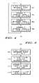
- FIG. 1is a schematic view of a fall detection system in accordance with a first embodiment of the invention
- FIG. 2is a schematic view of a fall detection system in accordance with a second embodiment of the invention.
- FIG. 3is a flow diagram of a fall detection method in accordance with an embodiment of the invention.
- FIG. 4is a flow diagram of a linear fall detection method in accordance with an embodiment of the invention.
- FIG. 5is a flow diagram of a non-linear fall detection method in accordance with an embodiment of the invention.
- FIG. 6is a graph of exemplary acceleration measurements during fall conditions in accordance with an embodiment of the invention.
- the present inventionprovides a system and method for fall detection of a human body through recognition of a fall signature.
- the system and methodprovides the ability to reliably detect falls and subsequent movement of the person to determine post-fall condition.
- Human body fall signaturescan be categorized as linear, or non-linear in nature.
- a linear fall signatureoccurs when a fall results without significant movement or outside force being applied.
- a linear fall signaturewould occur when an individual falls through a void or hole, as for example when a floor gives way beneath, or if they collapse straight down such as in a situation with police or a firefighter during a fire.
- a non-linear fall signaturewould occur when an individual falls with significant rotation of the body or when the fall is accompanied by additional external force, such as where one falls as a result of being struck by an object.
- FIG. 1illustrates in schematic view a fall detection system 100 according to a first embodiment of the present invention.
- Fall detection system 100includes a local monitoring unit 102 and a remote signal receiver 104 .
- Local monitoring unit 102comprises a plurality of accelerometers 106 , a processor 108 having inputs coupled to accelerometer 106 , and a transmitter for wirelessly transmitting a signal to remote signal receiver 104 , such as a wireless transmitter 110 coupled to processor 108 .
- the plurality of accelerometers 106provide acceleration measurements to processor 108 , representative of the current acceleration in all directions of the person wearing local monitoring unit 102 .
- accelerometers 106are worn where they can sense the acceleration of the wearer during a fall event.
- the term “fall event” as used hereinis defined as an event that results in a person coming to rest inadvertently on the ground or other lower level.
- processor 108receives the acceleration measurements and compares the acceleration measurements to a value range.
- processor 108compares combinations of acceleration measurements to a value range and further determines the smoothness of the acceleration measurement combinations. If the acceleration measurement combinations are within the value range and do not fall within a smoothness value range, then a non-linear fall event is occurring.
- Remote signal receiver 104is either a remotely located central monitoring site 112 or a portable receiving device 114 .
- Central monitoring site 112comprises a remote site that is configured to receive wirelessly transmitted fall detection signals from local monitoring unit 102 .
- Portable receiving device 114and more specifically a phone or paging device, is configured to receive wirelessly transmitted fall detection signals from local monitoring unit 102 and is designed to be worn by a person who is to be alerted if a fall event occurs.
- system 100can reliably detect a linear fall, or the more common non-linear fall, such as when the wearer's fall is accompanied with rotation or is initiated by additional external force.
- processor 108receives the acceleration measurements from accelerometer 106 and compares the acceleration measurements to a value range to determine if the person is experiencing a fall event. Subsequent to the detection of a fall event, processor 108 additionally compares further acceleration measurements to a value range stored in processor 108 and determines whether the acceleration measurements are within the value range to identify no additional movement or minimal movement of the wearer subsequent to the fall event. If the acceleration measurement combinations are within the value range and no movement or minimal movement is detected, then the wearer may not be conscious and emergency measures can be initiated.
- the monitoring service or individualis notified a fall event has occurred and emergency aid can be dispatched.
- the wearercan contact remote signal receiver 104 , and specifically the monitoring service in the case of an emergency, or lack thereof, and take appropriate measures.
- processor 108When a fall event is detected, processor 108 provides a fall detection signal to wireless transmitter 110 .
- wireless transmitter 110then transmits a signal directly to remote signal receiver 104 , and more specifically to central monitoring site 112 , to portable receiving device 114 , or both.
- FIG. 2illustrates in schematic view a fall detection system 200 according to a second embodiment of the present invention.
- Fall detection system 200includes a local monitoring unit 202 , a local signal receiving and transmitting unit 203 , and a remote signal receiver 204 .
- Fall detection system 200and more specifically local monitoring unit 202 , includes a plurality of accelerometers 206 , a processor 208 having inputs coupled to accelerometer 206 , and a wireless transmitter 210 coupled to processor 208 , for transmitting a fall detection signal to local signal receiving and transmitting unit 203 .
- Local signal receiving and transmitting unit 203receives the fall detection signal, and further generates an alert signal for transmission to remote signal receiver 204 .
- Local signal receiving and transmitting unit 203is intended to be positioned in the same general area as local monitoring unit 202 , such as in the home of an elderly wearer of local monitoring unit 202 .
- Local signal receiving and transmitting unit 203comprises a receiver 211 for receiving wireless transmissions from local monitoring unit 202 , a processor 213 for generating an alert signal, and a transmitter 215 .
- this embodimentprovides for wired or wireless transmission of an alert signal to remote signal receiver 204 via transmitter 215 .
- Remote signal receiver 204comprises a remotely located central monitoring site 212 and/or a portable receiving device 214 , such as a phone or paging device.
- Central monitoring site 212is configured to receive transmitted signals from local signal receiving and transmitting unit 203 .
- Portable receiving device 214is likewise configured to receive transmitted signals from local signal receiving and transmitting unit 203 and can be worn by a person monitoring potential fall events.
- a fall detection signalis generated by processor 208 and wirelessly transmitted by transmitter 215 to local signal receiving and transmitting unit 203 that in turn, receives and processes the fall detector signal and subsequently transmits an alert signal to remote signal receiver 204 via wired or wireless transmission.
- the plurality of accelerometers 206provide acceleration measurements to processor 208 . These measurements describe the current acceleration in all directions of the person wearing monitoring unit 202 .
- accelerometers 206are configured on the wearer where they can sense the acceleration of the wearer during a fall event.
- Processor 208receives the acceleration measurements and compares the acceleration measurements to a value range to determine if the person is experiencing a fall event.
- System 200can reliably detect a linear fall signature or a non-linear fall signature.
- processor 208receives the acceleration measurements and compares the acceleration measurements to a value range to determine if the person is experiencing a fall event. Subsequent to the detection of a fall event, processor 208 additionally compares further acceleration measurements to a value range stored in processor 208 and determines whether the acceleration measurements are within the value range to identify lack of movement, or minimal movement subsequent to the fall event. If the acceleration measurement combinations are within the value range and no movement or limited movement is detected, then the wearer may not be conscious and emergency measures can be taken.
- processor 208When a fall is detected, processor 208 provides a fall detection signal to transmitting device 210 , such as a wireless transmitting component.
- transmitting device 210wirelessly transmits a signal to a local signal receiving and transmitting unit 203 , and ultimately unit 203 transmits an alert signal to either central monitoring site 212 or to portable phone or paging device 214 .
- the present inventioncan be used to detect falls in a wide variety of instances. For example, it can be used to detect falls of the elderly, infirmed, or disabled. Upon the detection of a fall event, the central monitoring system would be alerted to send help. In addition, the detection of non-movement can be detected where the wearer is unconscious and not able to respond to the central monitor system. It can also be used to detect falls of community helpers, such as firefighters, police officers, or other individuals who are placed in harm's way. More particularly, the device can be used by those entering burning buildings and monitored by individuals remaining outside, to determine when a fall event occurs. In all these events, the present invention can be adapted to detect a fall, determine current state of consciousness via movement of the wearer, and provide a signal to a central monitoring system or portable device regarding the detected event.
- accelerometerscan be used in the system and method.
- One specific type of accelerometer that can be usedis a micromachined accelerometer.
- micromachined accelerometerscan be used to accurately measure acceleration using changes in capacitance.
- Capacitive micromachined accelerometersoffer high sensitivity with low noise and low power consumption and thus are ideal for many applications.
- These accelerometerstypically use surface micromachined capacitive sensing cells formed from semiconductor materials. Each cell includes two back-to-back capacitors with a center plate between the two outer plates. The center plate moves slightly in response to acceleration that is perpendicular to the plates. The movement of the center plate cause the distance between the plates to change.
- micromachined accelerometersare packaged together with an application specific integrated circuit (ASIC) that measures the capacitance, extracts the acceleration data from the difference between the two capacitors in the cell, and provides a signal that is proportional to the acceleration.
- ASICapplication specific integrated circuit
- more than one accelerometerwill be combined together in one package.
- some implementationsinclude three accelerometers, with each accelerometer is configure to measure acceleration in a different orthogonal axis. The three accelerometers are designed or packaged together with the ASIC used to measure and provide the acceleration signals for all three directions.
- Other implementationsare packaged with one accelerometer per device or two accelerometers per device. All of these implementations can be adapted for use in the fall detection system and method.
- One suitable accelerometer that can be adapted for use in the system and methodis a triple-axis accelerometer MMA7260Q available from Freescale Semiconductor, Inc. This accelerometer provides the advantage of measuring acceleration in all three directions with a single package.
- Other suitable accelerometersinclude dual axis accelerometer MMA6260Q and single axis accelerometer MMA1260D.
- Other types of accelerometers that can be usedinclude a combination of MMA6161Q, MMA6262Q, MMA6263Q, and MMA2260D with the MMA1260D or by mounting a device on its side to achieve 3-axis sensing. Of course, these are just some examples of the type of accelerometers that can be used in the fall detection system and method.
- FIG. 3illustrates a method 300 of fall detection according to the present invention.
- Method 300provides for the ability to detect a fall event by a wearer of a monitoring device, such as that described in FIGS. 1 and 2 .
- Method 300tests for both linear fall signatures and non-linear fall signatures. Detecting non-linear fall signatures is generally more complex due to the other actions operating on the device during the fall. Thus, method 300 first searches for linear fall signatures before searching for non-linear fall signatures.
- accelerometer measurement signalsare received ( 302 ).
- the accelerometer measurement signalsare provided by at least three accelerometers, where the at least three accelerometers are configured to measure acceleration in three orthogonal axes.
- there is at least one accelerometer measuring acceleration in an X-axisat least one accelerometer measuring acceleration in a Y-axis, and at least one accelerometer measuring acceleration in a Z-axis, where X, Y and Z are orthogonal axes.
- different arrangements of accelerometerscould be used in some embodiments.
- the next step ( 304 )is to determine if a linear fall signature is occurring.
- a linear fall signatureis occurring.
- one method of determining if a linear fall is occurringis to compare the measurement signals to a value range. If the measurement signals for each axis are each within a specified value range for a specified number of measurements, then a linear fall is determined to be occurring.
- One method of making this determinationis by comparing additional measurement signals to a value range. If the measurement signals for each axis are each within a specified value range for a specified number of measurements, then movement subsequent to the fall is detected and the next step 308 is to submit a signal to the remote signal receiver that the wearer of the monitoring unit has experienced a fall event, but appears to be conscious. If there is no subsequent movement detected, a fall detection signal is transmitted to the remote signal receiver (step 310 ). Appropriate action can then be taken to assist the person wearing the monitoring unit (step 312 ).
- the next step 314is to determine if the fall signature corresponds to a non-linear fall.
- one method of determining if the fall is a non-linear fallis by comparing combinations of acceleration measurements to a value range. Smoothness of the fall is also determined. If the acceleration measurement combinations are within the value range and not smooth, then a non-linear fall condition is occurring.
- one exemplary combination of measurements that can be usedis a sum of the squares of the measurements.
- the system and methodcan be adapted to determine if the fall was the result of being struck by falling debris.
- the previously sampled data points that were read before the fall occurredare analyzed to determine if the device experienced high accelerations in one or more directions. If such acceleration was present during the predetermined period before the fall, it can be assumed that the fall was initiated by external force, e.g., struck by falling debris.
- step 306it must next be determined if there is any movement subsequent to the fall, as previously described (step 306 ) If no movement is detected, a fall detection signal is sent to the remote signal receiver (step 310 ).
- step 302data is continuously received and evaluated to determine if a fall event is occurring.
- steps in method 300are merely exemplary, and that other combinations of steps or orders of steps can be used to provide fall detection.
- a fall detection signalcan be transmitted to the remote signal receiver irrespective of whether movement subsequent to the fall event is detected.
- FIG. 4illustrates a method 400 for detecting a linear fall signature.
- the method 400can be used to implement step 304 in method 300 ( FIG. 3 ).
- the method 400is based on the observation that a body having a linear fall signature will have acceleration measurements in all directions go toward a value that corresponds to zero g acceleration.
- the method 400compares measurements from each accelerometer to a selected value range, with the value range defining a set of acceleration values around zero g.
- the value range usedwould depend on a variety of factors. Typically, the larger the value range, the more likely a fall will be detected when it occurs. However, a larger value range will also increase the likelihood that non-fall conditions are erroneously determined to be falls. It should be noted that because this method compares the acceleration to a value range around zero g that some relatively low-end accelerometers with low effective measurement ranges can be used to provide the acceleration measurements and that expensive calibration can also be avoided.
- accelerometer measurement signals x, y and zare received, with the signals corresponding to measurements in X, Y and Z orthogonal directions.
- the format of the measurement signalswould typically depend on the accelerometer used and how the output of the accelerometer is processed.
- Typical accelerometersprovide a voltage that is proportional to the acceleration as an output. This output voltage can then be converted to a digital representation using an appropriate analog-to-digital converter. The conversion can be done by the processor, by the ASIC associated with accelerometers, or with separate converters.
- the number of bits used to represent the outputwould typically depend on a variety of factors, such as the desired resolution and the cost of components.
- an 8-bit solutioncan be used that would provide a range of 256 possible acceleration values, with a value of 128 corresponding to zero g.
- This nominal offset voltageprovides for the accelerometer to detect both positive and negative acceleration.
- the rate at which the analog-to-digital conversion is performedwould depend upon the speed of the various components. For example, a typical suitable converter would provide digital values from the analog signals at a rate of 200 Hz.
- the value rangedefines a margin of acceleration values around zero g.
- One exemplary value rangecovers within plus/minus four percent of zero g. In an 8-bit solution, this would correspond to acceleration values of within plus/minus 5 bits of one hundred twenty eight. Of course, this is just one example of a value range that can be used.
- step 406it is next determined if measurement signals y fall within the value range (step 406 ), and next it is determined if the measurements signals z fall within the value range (step 408 ).
- steps 404 , 406 and 408would be implemented such that a linear fall signature is detected only when measurement signals x, y and z are determined to be within the value range for a selected period of time. Requiring that each signal x, y and z be in the value range for a predetermined time period reduces the probability that random movements that result in near zero g measurement signals will be misinterpreted as indicative of a fall event. As one example, steps 404 , 406 and 408 can be implemented such that the signals are determined to fall within the value range when the signals are within the value range for at least 1/20 of a second.
- Steps 402 – 408 of method 400would be performed in real time, with the processor continually receiving measurement signals and determining if the past sets of measurement signals have been within the value range for a predetermined time period. This can be accomplished by continually loading the measurements into an appropriate FIFO buffer and evaluating the contents of the buffer to determine if the criteria are met for each set of measurement signals, then loading the next set of measurements, and removing the oldest set of measurements.
- the method 500can be used to implement step 306 in method 300 ( FIG. 3 ).
- the method 500is based on the observation that a non-linear falling body signature will have certain combinations of acceleration measurements go toward a value that corresponds to zero g acceleration.
- the method 500compares combinations of measurements from each accelerometer to a selected value range, with the value range defining a combination of acceleration values around zero g.
- the method 500determines the smoothness of the combination of acceleration values, generally referred to herein as S factor values, and determines if they are within the value range.
- accelerometer measurement signals x, y and zare received with the signals corresponding to measurements in X, Y and Z orthogonal directions (step 502 ).
- the format of the measurement signalswould typically depend on the accelerometer used and how the output of the accelerometer is processed. For example, an 8-bit solution can again be used that provides digital measurement values at a rate of 200 Hz.
- the next step ( 504 )is to calculate the S factor values from the measurement signals.
- the S factoris defined and calculated to provide a combination of measurement values that is a good indication of non-linear falling body, such as to what degree external influence is acting upon it, such as falling debris.
- a variety of types of combinationscan be used.
- a combination of measurement values called S factor valuesare calculated that can be used to determine if a non-linear fall signature exists or to what degree external influence is acting upon the body falling.
- the value rangedefines a margin of S factor values around zero g.
- One exemplary value rangeis to select a range that covers within +/3 to 12 percent of zero g. In an exemplary 8-bit solution, this would correspond to S factor values of within +/ ⁇ 2 to 7 bits of 128. Of course, this is just one example of a value range that can be used.
- the smoothness of the S factor valuescan be calculated by determining the amount of change between consecutive S factor values and comparing the amount of change to a threshold delta value.
- the threshold delta value usedwould again depend on a variety of factors. In an 8-bit solution, the threshold delta value can be +/ ⁇ 2 to 7 bits. Thus, if consecutive S factor values are within +/ ⁇ 2 to 7 bits then the S factor is smooth at that time.
- steps 506 and 508would be implemented such that a non-linear fall signature is detected only when the S factor values are determined to be within the value range and smooth for a selected period of time. Requiring the S factor values to be in the value range and smooth for a predetermined time period reduces the probability that random movements will be misinterpreted as indicative of a non-linear fall condition.
- steps 506 and 508can be implemented such that the S factor values are determined to be indicative of a non-linear fall when they are within the value range and be smooth for at least 50 to 150 milliseconds.
- Steps 502 – 508 of method 500would be performed in real time, with the processor continually receiving measurement signals and determining if the past sets of measurement signals have S factor values that are within the value range and smooth. This can be accomplished by continually loading the measurements into an appropriate FIFO buffer and evaluating the contents of the buffer to determine if the criteria are met for resulting S factor values, then loading the next set of measurements and removing the oldest set of measurements.
- FIG. 6is a graph 600 of exemplary accelerometer measurement signals x, y and z taken over a time period during which a fall event occurs.
- Graph 600illustrates a fall condition occurring at time T 1 .
- the measurement signals x, y and zall are within a value range of zero g.
- a fall eventis detected when the signals x, y and z are simultaneously within the value range for a predetermined time period.
- the signalsleave the value range, thus indicating the resulting impact shock.
- the amount of time between T 1 and T 2is the approximate fall time. If necessary, this fall time can be used to calculate the fall distance.
- the fall detection systemcan be implemented with a variety of different types and configurations of devices. As discussed above, the system is implemented with a processor that performs the computation and control functions of the fall detector.
- the processormay comprise any suitable type of processing device, including single integrated circuits such as a microprocessor, or combinations of devices working in cooperation to accomplish the functions of a processing unit. In addition, the processor may part of the electronic device's core system or a device separate to the core system.
- a suitable state machine or other control circuitry integrated with the accelerometerscan implement the plurality of accelerometers and the processor in a single device solution. In such a system circuitry can be used to directly determine if the accelerometer plates are close to a zero position, and provide the warning to the device.
- the processorcan comprise special purpose hardware configured for fault detection.
- the processorcan comprise a programmable processor that executes programs stored in a suitable memory, with the programs configured to provide fault detection.
- signal bearing mediainclude: recordable media such as floppy disks, hard drives, memory cards and optical disks, and transmission media such as digital and analog communication links, including wireless communication links.
- the present inventionthus provides a system for determining if a human body has fallen, the system comprising: a local monitoring unit and a remote signal receiver comprising one of a central monitoring site or a portable electronic device.
- the local monitoring unitincludes a plurality of accelerometers, a processor and a wireless transmitter.
- the plurality of accelerometerscan be micro machined accelerometers.
- the plurality of accelerometersmeasure acceleration of a human body in a plurality of directions and produce a plurality of acceleration measurements.
- the processorreceives the plurality of acceleration measurements from the plurality of accelerometers, compares them to a value range and generates a signal if the plurality of acceleration measurements are within the value range indicating a fall event has occurred.
- the wireless transmittertransmits the signal to a remote signal receiver.
- the processorcan determine if the plurality of acceleration measurements are within the value range for a predetermined number of consecutive acceleration measurements.
- the processorcan further determine if a non-linear fall is occurring by determining if the plurality of acceleration measurements has smoothness with a specified range by determining if a selected number of consecutive acceleration measurements each has a change less than a threshold delta value.
- the plurality of accelerometersincludes a first accelerometer providing a first acceleration measurement x, a second accelerometer providing a second acceleration measurement y, and a third accelerometer providing a third acceleration measurement z.
- the processordetermines if the plurality of acceleration measurements has smoothness within a specified range by determining if x 2 +y 2 +z 2 has a change less than a threshold delta value for a selected number of consecutive acceleration measurements.
- the processorfurther determines if a detected fall event was accompanied by external force by determining if a combination of the acceleration measurements exceeded a threshold value in a time period prior to the detected fall event.
- the present inventionfurther provides for a system for determining if a human body is falling, wherein the system comprises a local monitoring unit including a first accelerometer providing a first acceleration measurements x, a second accelerometer providing a second acceleration measurements y, and a third accelerometer providing a third acceleration measurements z.
- a local monitoring unitfurther includes a processor for receiving the first acceleration measurements x, the second acceleration measurements y, and the third acceleration measurements z. The processor compares the measurements to a value range, and determines whether a fall event is occurring and generates a signal in response to the detected fall event that is wirelessly transmitted to the remote signal receiver.
- the systemcan further include a local signal receiving and transmitting unit for receiving the wireless signal generated by the local monitoring unit, and transmitting the signal to the remote signal receiver.
- the systemcan determine if movement subsequent to the fall event is present by receiving a plurality of acceleration measurements from the plurality of accelerometers subsequent to the fall event.
- the systemcompares the plurality of acceleration measurements to a value range and generates a signal if the plurality of acceleration measurements are within the value range indicating movement subsequent to the fall event.
- the present inventionfurther provides for a method for determining if human body is falling, wherein the method comprises the steps of measuring acceleration of a human body wearing a monitoring unit in a plurality of directions and producing a plurality of acceleration measurements.
- the plurality acceleration measurementsare compared to a value range to determine if they are within the value range indicating a fall event has occurred.
- a signalis in response to the fall event and transmitted to a remote signal receiver.
- the plurality of acceleration measurementsinclude a first acceleration measurement x, a second acceleration measurement y, and a third acceleration measurement z.
- the accelerometersare micromachined accelerometers.
- the plurality of acceleration measurementsare received from a first accelerometer measuring acceleration in a X direction, a second accelerometer measuring acceleration in a Y direction, and a third accelerometer measuring acceleration in a Z direction, where X, Y and Z are perpendicular to each other.
- the processorcompares the first acceleration measurements x, the second acceleration measurements y, and the third acceleration measurements z to a value range. If the first acceleration measurements x, the second acceleration measurements y, and the third acceleration measurements z are each within the value range for a first selected number of measurements, it determines a fall event is occurring.
- the processorcan further combine the first acceleration measurements x, the second acceleration measurements y, and the third acceleration measurements z into a combination of x 2 +y 2 +z 2 values and compare the combination of x 2 +y 2 +z 2 values to a second value range, to determine if the combination of x 2 +y 2 +z 2 values has an amount of change less than a threshold delta value for a second selected number of measurements. This measurement will aid in determining if a detected fall was accompanied by external force by determining if a combination of the acceleration measurements exceeded a threshold value in a time period prior to the detected fall.
Landscapes
- Health & Medical Sciences (AREA)
- Life Sciences & Earth Sciences (AREA)
- Engineering & Computer Science (AREA)
- Biomedical Technology (AREA)
- General Health & Medical Sciences (AREA)
- Public Health (AREA)
- Medical Informatics (AREA)
- Physics & Mathematics (AREA)
- Biophysics (AREA)
- Heart & Thoracic Surgery (AREA)
- Molecular Biology (AREA)
- Surgery (AREA)
- Animal Behavior & Ethology (AREA)
- Veterinary Medicine (AREA)
- Pathology (AREA)
- Business, Economics & Management (AREA)
- Computer Networks & Wireless Communication (AREA)
- Physiology (AREA)
- Oral & Maxillofacial Surgery (AREA)
- Gerontology & Geriatric Medicine (AREA)
- Dentistry (AREA)
- Emergency Management (AREA)
- General Physics & Mathematics (AREA)
- General Business, Economics & Management (AREA)
- Epidemiology (AREA)
- Primary Health Care (AREA)
- Emergency Alarm Devices (AREA)
- Alarm Systems (AREA)
- Accommodation For Nursing Or Treatment Tables (AREA)
Abstract
Description
SFactor=x2+y2+z2
where x, y and z are the acceleration measurement signals. In this equation, the Sfactorcombination is defined as the sum of the squares of the measurement signals, where the measurement signals are in g's (e.g., x=(x1−xoffset)÷sensitivity). Of course, other equations and calculations can be used to define and calculate the Sfactor. Thus in
Claims (16)
Priority Applications (3)
| Application Number | Priority Date | Filing Date | Title |
|---|---|---|---|
| US11/087,339US7248172B2 (en) | 2005-03-22 | 2005-03-22 | System and method for human body fall detection |
| PCT/US2006/002647WO2006101587A2 (en) | 2005-03-22 | 2006-01-25 | System and method for human body fall detection |
| JP2008502981AJP4949377B2 (en) | 2005-03-22 | 2006-01-25 | System and method for human body fall detection |
Applications Claiming Priority (1)
| Application Number | Priority Date | Filing Date | Title |
|---|---|---|---|
| US11/087,339US7248172B2 (en) | 2005-03-22 | 2005-03-22 | System and method for human body fall detection |
Publications (2)
| Publication Number | Publication Date |
|---|---|
| US20060214806A1 US20060214806A1 (en) | 2006-09-28 |
| US7248172B2true US7248172B2 (en) | 2007-07-24 |
Family
ID=37024272
Family Applications (1)
| Application Number | Title | Priority Date | Filing Date |
|---|---|---|---|
| US11/087,339Expired - LifetimeUS7248172B2 (en) | 2005-03-22 | 2005-03-22 | System and method for human body fall detection |
Country Status (3)
| Country | Link |
|---|---|
| US (1) | US7248172B2 (en) |
| JP (1) | JP4949377B2 (en) |
| WO (1) | WO2006101587A2 (en) |
Cited By (31)
| Publication number | Priority date | Publication date | Assignee | Title |
|---|---|---|---|---|
| US20090031803A1 (en)* | 2005-01-31 | 2009-02-05 | Hitachi Metals, Ltd. | Fall detecting method and fall detecting device |
| US20090045966A1 (en)* | 2007-07-20 | 2009-02-19 | Marko Rocznik | Clothing means having a sensor element for detecting a left position |
| US20090076419A1 (en)* | 2007-05-23 | 2009-03-19 | Cybernet Systems Corporation | Loss-of-balance and fall detection system |
| US20100217533A1 (en)* | 2009-02-23 | 2010-08-26 | Laburnum Networks, Inc. | Identifying a Type of Motion of an Object |
| US20100302041A1 (en)* | 2009-05-27 | 2010-12-02 | International Business Machines Corporation | Monitoring Patterns of Motion |
| US20110025493A1 (en)* | 2005-03-11 | 2011-02-03 | Aframe Digital, Inc. | Mobile wireless customizable health and condition monitor |
| US20110066383A1 (en)* | 2009-09-15 | 2011-03-17 | Wellcore Corporation | Indentifying One or More Activities of an Animate or Inanimate Object |
| US20110066064A1 (en)* | 2009-09-15 | 2011-03-17 | Wellcore Corporation | Method and System for Analyzing Breathing of a User |
| WO2011152911A1 (en)* | 2010-06-03 | 2011-12-08 | Cogility Software Corporation | System and method for temporal correlation of observables |
| WO2012119903A1 (en) | 2011-03-04 | 2012-09-13 | Deutsche Telekom Ag | Method and system for detecting a fall and issuing an alarm |
| US20140338445A1 (en)* | 2013-05-14 | 2014-11-20 | Wistron Corporation | Method of utilizing mobile device to detect emergency and related emergency detecting system |
| US9013297B1 (en) | 2014-10-17 | 2015-04-21 | Ockham Razor Ventures, LLC | Condition responsive indication assembly and method |
| US9470704B2 (en) | 2009-02-23 | 2016-10-18 | Nortek Security & Control Llc | Wearable motion sensing device |
| US9872637B2 (en) | 2010-04-21 | 2018-01-23 | The Rehabilitation Institute Of Chicago | Medical evaluation system and method using sensors in mobile devices |
| US9892612B2 (en) | 2013-12-20 | 2018-02-13 | Koninklijke Philips N.V. | Method for responding to a detected fall and an apparatus for implementing the same |
| CN107710293A (en)* | 2015-04-30 | 2018-02-16 | 霍尼韦尔国际公司 | System for Integrating Multi-Sensor Data to Predict Fall Risk |
| US20180168265A1 (en)* | 2014-10-17 | 2018-06-21 | Guardhat, Inc. | Condition Responsive Indication Assembly and Method |
| US10169972B1 (en) | 2011-06-09 | 2019-01-01 | Blackline Safety Corp. | Method and system for monitoring the safety of field workers |
| US10325229B2 (en) | 2016-03-16 | 2019-06-18 | Triax Technologies, Inc. | Wearable sensor for tracking worksite events including sensor removal |
| US10769562B2 (en) | 2016-03-16 | 2020-09-08 | Triax Technologies, Inc. | Sensor based system and method for authorizing operation of worksite equipment using a locally stored access control list |
| US11076777B2 (en) | 2016-10-13 | 2021-08-03 | Masimo Corporation | Systems and methods for monitoring orientation to reduce pressure ulcer formation |
| US11089963B2 (en)* | 2015-08-31 | 2021-08-17 | Masimo Corporation | Systems and methods for patient fall detection |
| US11170616B2 (en) | 2016-03-16 | 2021-11-09 | Triax Technologies, Inc. | System and interfaces for managing workplace events |
| US11436907B2 (en) | 2011-06-22 | 2022-09-06 | Thinkware Corporation | Safety service system and method thereof |
| USD974193S1 (en) | 2020-07-27 | 2023-01-03 | Masimo Corporation | Wearable temperature measurement device |
| USD980091S1 (en) | 2020-07-27 | 2023-03-07 | Masimo Corporation | Wearable temperature measurement device |
| USD1000975S1 (en) | 2021-09-22 | 2023-10-10 | Masimo Corporation | Wearable temperature measurement device |
| US11810032B2 (en) | 2016-03-16 | 2023-11-07 | Triax Technologies, Inc. | Systems and methods for low-energy wireless applications using networked wearable sensors |
| US11974833B2 (en) | 2020-03-20 | 2024-05-07 | Masimo Corporation | Wearable device for noninvasive body temperature measurement |
| USD1048908S1 (en) | 2022-10-04 | 2024-10-29 | Masimo Corporation | Wearable sensor |
| USD1072837S1 (en) | 2020-10-27 | 2025-04-29 | Masimo Corporation | Display screen or portion thereof with graphical user interface |
Families Citing this family (37)
| Publication number | Priority date | Publication date | Assignee | Title |
|---|---|---|---|---|
| US7299034B2 (en)* | 2005-06-21 | 2007-11-20 | Lawrence Kates | System and method for wearable electronics |
| JP4465403B2 (en)* | 2006-10-02 | 2010-05-19 | 三井松島産業株式会社 | Moving body position monitoring system |
| US8260570B2 (en)* | 2007-01-22 | 2012-09-04 | National University Of Singapore | Method and system for fall-onset detection |
| TW200842767A (en)* | 2007-04-19 | 2008-11-01 | Koninkl Philips Electronics Nv | Multi-sensory fall detection system |
| JP5539857B2 (en)* | 2007-04-19 | 2014-07-02 | コーニンクレッカ フィリップス エヌ ヴェ | Fall detection system |
| US8152745B2 (en)* | 2008-02-25 | 2012-04-10 | Shriners Hospitals For Children | Activity monitoring |
| KR100988459B1 (en)* | 2008-06-24 | 2010-10-18 | 한국전자통신연구원 | Fall detection device and method |
| FR2935189B1 (en)* | 2008-08-20 | 2011-11-04 | Eads Secure Networks | MOBILE COMMUNICATION EQUIPMENT, METHOD AND DEVICE FOR DETECTING EVENTS RELATING TO THE MONITORING OF VALUE OBJECTS |
| US8749391B2 (en)* | 2008-10-16 | 2014-06-10 | Koninklijke Philips N.V. | Fall detection system |
| JP2012508943A (en)* | 2008-11-14 | 2012-04-12 | コーニンクレッカ フィリップス エレクトロニクス エヌ ヴィ | Method and apparatus for fall detection and alarm |
| JP5512695B2 (en)* | 2008-11-28 | 2014-06-04 | コーニンクレッカ フィリップス エヌ ヴェ | Method, apparatus and program for detecting falls |
| EP2263533A1 (en)* | 2009-06-18 | 2010-12-22 | Deutsche Telekom AG | Enhancing security and emergency functionalities in mobile phones based on detection of physical shocks |
| DE102009036828B4 (en)* | 2009-08-11 | 2014-02-13 | Schuberth Gmbh | System for detecting an accident situation and emergency call activation and method thereto |
| CN101950464B (en)* | 2010-09-17 | 2012-10-17 | 中国科学院深圳先进技术研究院 | Method and system for fall detection and alarm |
| CN102393992A (en)* | 2011-03-15 | 2012-03-28 | 苏州摩多物联科技有限公司 | Alarm terminal capable of automatically detecting tumble of human body |
| KR101178936B1 (en)* | 2011-04-06 | 2012-09-03 | 계명대학교 산학협력단 | Automatic falling alert method, terminal, and system using smartphone |
| GB2491376B (en)* | 2011-06-01 | 2014-01-08 | Fall Safe Assist Ltd | Hip impact protector |
| US20140358041A1 (en)* | 2012-04-18 | 2014-12-04 | Matthew Alan Hopcroft | Assessing physical stability of a patient using an accelerometer |
| CN102972905B (en)* | 2012-11-23 | 2015-01-14 | 南京工业大学 | Tumble alarm shoes |
| CN103040547B (en)* | 2012-12-24 | 2015-01-07 | 中国科学院深圳先进技术研究院 | Portable fall protector |
| US20150269825A1 (en)* | 2014-03-20 | 2015-09-24 | Bao Tran | Patient monitoring appliance |
| US9159213B1 (en)* | 2014-07-17 | 2015-10-13 | National Chung Shan Institute Of Science And Technology | Motion detection method and device |
| US10347108B2 (en)* | 2015-01-16 | 2019-07-09 | City University Of Hong Kong | Monitoring user activity using wearable motion sensing device |
| BR112018013439A2 (en)* | 2015-12-30 | 2018-12-04 | 3M Innovative Properties Co | electronic fall event communication system |
| TWI592832B (en)* | 2016-01-21 | 2017-07-21 | 拓連科技股份有限公司 | Methods and systems of signal generation for an electronic device, and related computer program products |
| TWM537280U (en)* | 2016-07-06 | 2017-02-21 | Idesyn Semiconductor Corp | Fall detection system analyzing fall severity, and wearable device thereof |
| CN106097650A (en)* | 2016-08-11 | 2016-11-09 | 北京小米移动软件有限公司 | The alarm method of terminal, device and terminal |
| US10506990B2 (en) | 2016-09-09 | 2019-12-17 | Qualcomm Incorporated | Devices and methods for fall detection based on phase segmentation |
| KR20230070536A (en)* | 2016-10-05 | 2023-05-23 | 마이 메딕 왓치 피티와이 엘티디 | Alert system |
| US12367751B2 (en) | 2016-10-05 | 2025-07-22 | My Medic Watch Pty Ltd | Alert system |
| JP6439016B1 (en)* | 2017-07-19 | 2018-12-19 | エア・ウォーター防災株式会社 | Alarm system |
| EP3828855A1 (en) | 2019-11-29 | 2021-06-02 | Koninklijke Philips N.V. | Personalized fall detector |
| CN110989330A (en)* | 2019-12-25 | 2020-04-10 | 张敏 | Special intelligent wrist-watch of old person |
| EP3906843B1 (en)* | 2020-05-08 | 2022-12-14 | Pacesetter, Inc. | System for verifying a pathologic episode using an accelerometer |
| JP7571398B2 (en)* | 2020-06-18 | 2024-10-23 | コニカミノルタ株式会社 | Information processing device, monitoring system, and control program |
| US11055981B1 (en)* | 2020-11-13 | 2021-07-06 | Aetna Inc. | Systems and methods for using primary and redundant devices for detecting falls |
| ES2919332B2 (en)* | 2021-01-22 | 2023-08-10 | Univ Salamanca | FALL WARNING DEVICE AT DIFFERENT LEVEL OF CLIPAGE TYPE |
Citations (2)
| Publication number | Priority date | Publication date | Assignee | Title |
|---|---|---|---|---|
| US6160478A (en)* | 1998-10-27 | 2000-12-12 | Sarcos Lc | Wireless health monitoring system |
| US7095331B2 (en)* | 1999-09-15 | 2006-08-22 | Ilife Solutions, Inc. | System and method for detecting motion of a body |
Family Cites Families (2)
| Publication number | Priority date | Publication date | Assignee | Title |
|---|---|---|---|---|
| JP2878135B2 (en)* | 1994-11-30 | 1999-04-05 | 日本電気移動通信株式会社 | Emergency call system |
| JP3925649B2 (en)* | 2003-02-19 | 2007-06-06 | 独立行政法人科学技術振興機構 | Fall detection method and fall rescue method |
- 2005
- 2005-03-22USUS11/087,339patent/US7248172B2/ennot_activeExpired - Lifetime
- 2006
- 2006-01-25WOPCT/US2006/002647patent/WO2006101587A2/enactiveApplication Filing
- 2006-01-25JPJP2008502981Apatent/JP4949377B2/enactiveActive
Patent Citations (3)
| Publication number | Priority date | Publication date | Assignee | Title |
|---|---|---|---|---|
| US6160478A (en)* | 1998-10-27 | 2000-12-12 | Sarcos Lc | Wireless health monitoring system |
| US6433690B2 (en)* | 1998-10-27 | 2002-08-13 | Sarcos, L.C. | Elderly fall monitoring method and device |
| US7095331B2 (en)* | 1999-09-15 | 2006-08-22 | Ilife Solutions, Inc. | System and method for detecting motion of a body |
Cited By (65)
| Publication number | Priority date | Publication date | Assignee | Title |
|---|---|---|---|---|
| US7690253B2 (en)* | 2005-01-31 | 2010-04-06 | Hitachi Metals, Ltd. | Fall detecting method and fall detecting device |
| US20090031803A1 (en)* | 2005-01-31 | 2009-02-05 | Hitachi Metals, Ltd. | Fall detecting method and fall detecting device |
| US8618930B2 (en)* | 2005-03-11 | 2013-12-31 | Aframe Digital, Inc. | Mobile wireless customizable health and condition monitor |
| US20110025493A1 (en)* | 2005-03-11 | 2011-02-03 | Aframe Digital, Inc. | Mobile wireless customizable health and condition monitor |
| US20090076419A1 (en)* | 2007-05-23 | 2009-03-19 | Cybernet Systems Corporation | Loss-of-balance and fall detection system |
| US20090045966A1 (en)* | 2007-07-20 | 2009-02-19 | Marko Rocznik | Clothing means having a sensor element for detecting a left position |
| US20100217533A1 (en)* | 2009-02-23 | 2010-08-26 | Laburnum Networks, Inc. | Identifying a Type of Motion of an Object |
| US9470704B2 (en) | 2009-02-23 | 2016-10-18 | Nortek Security & Control Llc | Wearable motion sensing device |
| US8812258B2 (en) | 2009-02-23 | 2014-08-19 | Numera, Inc. | Identifying a type of motion of an object |
| US20100302041A1 (en)* | 2009-05-27 | 2010-12-02 | International Business Machines Corporation | Monitoring Patterns of Motion |
| US8081082B2 (en)* | 2009-05-27 | 2011-12-20 | International Business Machines Corporation | Monitoring patterns of motion |
| US8560267B2 (en) | 2009-09-15 | 2013-10-15 | Imetrikus, Inc. | Identifying one or more activities of an animate or inanimate object |
| US20110066383A1 (en)* | 2009-09-15 | 2011-03-17 | Wellcore Corporation | Indentifying One or More Activities of an Animate or Inanimate Object |
| US8972197B2 (en) | 2009-09-15 | 2015-03-03 | Numera, Inc. | Method and system for analyzing breathing of a user |
| US20110066064A1 (en)* | 2009-09-15 | 2011-03-17 | Wellcore Corporation | Method and System for Analyzing Breathing of a User |
| US10750977B2 (en) | 2010-04-21 | 2020-08-25 | Rehabilitation Institute Of Chicago | Medical evaluation system and method using sensors in mobile devices |
| US9872637B2 (en) | 2010-04-21 | 2018-01-23 | The Rehabilitation Institute Of Chicago | Medical evaluation system and method using sensors in mobile devices |
| US8412663B2 (en) | 2010-06-03 | 2013-04-02 | Drumright Group, Llc. | System and method for temporal correlation of observables based on timing ranges associated with observations |
| WO2011152911A1 (en)* | 2010-06-03 | 2011-12-08 | Cogility Software Corporation | System and method for temporal correlation of observables |
| US8825590B2 (en) | 2010-06-03 | 2014-09-02 | Drumright Group, Llc. | System and method for temporal correlation of observables based on timing associated with observations |
| WO2012036958A3 (en)* | 2010-09-16 | 2012-07-12 | Wellcore Corporation | Identifying one or more activities of an animate or inanimate object |
| WO2012119903A1 (en) | 2011-03-04 | 2012-09-13 | Deutsche Telekom Ag | Method and system for detecting a fall and issuing an alarm |
| US10546477B2 (en) | 2011-06-09 | 2020-01-28 | Blackline Safety Corp. | Method and system for monitoring the safety of field workers |
| US10169972B1 (en) | 2011-06-09 | 2019-01-01 | Blackline Safety Corp. | Method and system for monitoring the safety of field workers |
| US11436907B2 (en) | 2011-06-22 | 2022-09-06 | Thinkware Corporation | Safety service system and method thereof |
| US12020549B2 (en) | 2011-06-22 | 2024-06-25 | Thinkware Corporation | Safety service system and method thereof |
| US9261527B2 (en)* | 2013-05-14 | 2016-02-16 | Wistron Corporation | Method of utilizing mobile device to detect emergency and related emergency detecting system |
| US20140338445A1 (en)* | 2013-05-14 | 2014-11-20 | Wistron Corporation | Method of utilizing mobile device to detect emergency and related emergency detecting system |
| US9892612B2 (en) | 2013-12-20 | 2018-02-13 | Koninklijke Philips N.V. | Method for responding to a detected fall and an apparatus for implementing the same |
| US20180168265A1 (en)* | 2014-10-17 | 2018-06-21 | Guardhat, Inc. | Condition Responsive Indication Assembly and Method |
| US20160110992A1 (en)* | 2014-10-17 | 2016-04-21 | Ockham Razor Ventures, LLC | Condition responsive indication assembly and method |
| US9538801B2 (en)* | 2014-10-17 | 2017-01-10 | Guardhat, Inc. | Condition responsive indication assembly and method |
| US9177458B1 (en)* | 2014-10-17 | 2015-11-03 | Ockham Razor Ventures, LLC | Condition responsive indication assembly and method |
| US9538800B2 (en)* | 2014-10-17 | 2017-01-10 | Guardhat, Inc. | Condition responsive indication assembly and method |
| US9013297B1 (en) | 2014-10-17 | 2015-04-21 | Ockham Razor Ventures, LLC | Condition responsive indication assembly and method |
| US20160106173A1 (en)* | 2014-10-17 | 2016-04-21 | Ockham Razor Ventures, LLC | Condition responsive indication assembly and method |
| US11000088B2 (en) | 2014-10-17 | 2021-05-11 | Guardhat, Inc. | Condition responsive indication assembly |
| US10667571B2 (en)* | 2014-10-17 | 2020-06-02 | Guardhat, Inc. | Condition responsive indication assembly and method |
| CN107710293A (en)* | 2015-04-30 | 2018-02-16 | 霍尼韦尔国际公司 | System for Integrating Multi-Sensor Data to Predict Fall Risk |
| US11120679B2 (en)* | 2015-04-30 | 2021-09-14 | Honeywell International Inc. | System for integrating multiple sensor data to predict a fall risk |
| US20210366258A1 (en)* | 2015-04-30 | 2021-11-25 | Honeywell International Inc. | System For Integrating Multiple Sensor Data To Predict A Fall Risk |
| US11763655B2 (en)* | 2015-04-30 | 2023-09-19 | Honeywell International Inc. | System for integrating multiple sensor data to predict a fall risk |
| US20180357879A1 (en)* | 2015-04-30 | 2018-12-13 | Honeywell International Inc. | System for integrating multiple sensor data to predict a fall risk |
| US12150739B2 (en) | 2015-08-31 | 2024-11-26 | Masimo Corporation | Systems and methods for patient fall detection |
| US11576582B2 (en) | 2015-08-31 | 2023-02-14 | Masimo Corporation | Patient-worn wireless physiological sensor |
| US11089963B2 (en)* | 2015-08-31 | 2021-08-17 | Masimo Corporation | Systems and methods for patient fall detection |
| US12133717B2 (en) | 2015-08-31 | 2024-11-05 | Masimo Corporation | Systems and methods for patient fall detection |
| US10692024B2 (en) | 2016-03-16 | 2020-06-23 | Triax Technologies, Inc. | Wireless mesh network system for monitoring worksite events including detecting false events |
| US10769562B2 (en) | 2016-03-16 | 2020-09-08 | Triax Technologies, Inc. | Sensor based system and method for authorizing operation of worksite equipment using a locally stored access control list |
| US10891567B2 (en) | 2016-03-16 | 2021-01-12 | Triax Technologies, Inc. | System and interfaces for managing workplace events |
| US11170616B2 (en) | 2016-03-16 | 2021-11-09 | Triax Technologies, Inc. | System and interfaces for managing workplace events |
| US10878352B2 (en)* | 2016-03-16 | 2020-12-29 | Triax Technologies, Inc. | Mesh based system and method for tracking worksite events experienced by workers via a wearable sensor |
| US10325229B2 (en) | 2016-03-16 | 2019-06-18 | Triax Technologies, Inc. | Wearable sensor for tracking worksite events including sensor removal |
| US11810032B2 (en) | 2016-03-16 | 2023-11-07 | Triax Technologies, Inc. | Systems and methods for low-energy wireless applications using networked wearable sensors |
| US10528902B2 (en) | 2016-03-16 | 2020-01-07 | Triax Technologies, Inc. | System and interfaces for managing workplace events |
| US11076777B2 (en) | 2016-10-13 | 2021-08-03 | Masimo Corporation | Systems and methods for monitoring orientation to reduce pressure ulcer formation |
| US12364403B2 (en) | 2020-03-20 | 2025-07-22 | Masimo Corporation | Wearable device for noninvasive body temperature measurement |
| US11974833B2 (en) | 2020-03-20 | 2024-05-07 | Masimo Corporation | Wearable device for noninvasive body temperature measurement |
| USD980091S1 (en) | 2020-07-27 | 2023-03-07 | Masimo Corporation | Wearable temperature measurement device |
| USD1022729S1 (en) | 2020-07-27 | 2024-04-16 | Masimo Corporation | Wearable temperature measurement device |
| USD974193S1 (en) | 2020-07-27 | 2023-01-03 | Masimo Corporation | Wearable temperature measurement device |
| USD1072837S1 (en) | 2020-10-27 | 2025-04-29 | Masimo Corporation | Display screen or portion thereof with graphical user interface |
| USD1050910S1 (en) | 2021-09-22 | 2024-11-12 | Masimo Corporation | Portion of a wearable temperature measurement device |
| USD1000975S1 (en) | 2021-09-22 | 2023-10-10 | Masimo Corporation | Wearable temperature measurement device |
| USD1048908S1 (en) | 2022-10-04 | 2024-10-29 | Masimo Corporation | Wearable sensor |
Also Published As
| Publication number | Publication date |
|---|---|
| JP2008535055A (en) | 2008-08-28 |
| US20060214806A1 (en) | 2006-09-28 |
| JP4949377B2 (en) | 2012-06-06 |
| WO2006101587A3 (en) | 2007-06-14 |
| WO2006101587A2 (en) | 2006-09-28 |
Similar Documents
| Publication | Publication Date | Title |
|---|---|---|
| US7248172B2 (en) | System and method for human body fall detection | |
| US7423537B2 (en) | Procedure and system for detecting a person's fall | |
| EP2147421B1 (en) | Fall detection system | |
| US9176932B2 (en) | Method for detecting falls and a fall detector | |
| CN102187371B (en) | Fall detection system and method of operating fall detection system | |
| US9638711B2 (en) | Method and system for discerning a false positive in a fall detection signal | |
| US9402568B2 (en) | Method and system for detecting a fall based on comparing data to criteria derived from multiple fall data sets | |
| EP2348997B1 (en) | Fall detection system | |
| Er et al. | Non-intrusive fall detection monitoring for the elderly based on fuzzy logic | |
| US20170372582A1 (en) | Device for monitoring and preventing slump and processing method thereof | |
| US20150164434A1 (en) | Method and apparatus for detecting a critical situation of a subject | |
| US20050038327A1 (en) | Pulse abnormality monitor and pulse abnormality warning system | |
| EP1779772B1 (en) | System for analysing a person's activity and for automatic fall detection | |
| EP2084688A1 (en) | System for fall prevention and a method for fall prevention using such a system | |
| KR20120108335A (en) | Emergency monitoring system based on newly developed fall detection algorithm | |
| EP1974662A1 (en) | Fall detector | |
| US20230252884A1 (en) | Devices, systems and methods for fall detection and preventing false alarms | |
| Bianchi et al. | Falls event detection using triaxial accelerometry and barometric pressure measurement | |
| Er et al. | Wearable solution for robust fall detection | |
| JP6491504B2 (en) | Fall detection terminal and program | |
| CN112233373B (en) | A method for eliminating false alarms of a call device by assisting motion measurement of a call device | |
| Sheng et al. | Development of wearable sensor-based fall detection system for elderly using iot | |
| Moon et al. | Implementation of fall direction detector using a single gyroscope | |
| Van Thanh et al. | Development of a real-time supported system for firefighters in emergency cases | |
| WO2022077107A1 (en) | System and method to detect a man-down situation using intra-aural inertial measurement units |
Legal Events
| Date | Code | Title | Description |
|---|---|---|---|
| AS | Assignment | Owner name:FREESCALE SEMICONDUCTOR, INC., TEXAS Free format text:ASSIGNMENT OF ASSIGNORS INTEREST;ASSIGNORS:CLIFFORD, MICHELLE A.;BORRAS, RODRIGO L.;GOMEZ, LETICIA;REEL/FRAME:016413/0715;SIGNING DATES FROM 20050321 TO 20050322 | |
| AS | Assignment | Owner name:CITIBANK, N.A. AS COLLATERAL AGENT, NEW YORK Free format text:SECURITY AGREEMENT;ASSIGNORS:FREESCALE SEMICONDUCTOR, INC.;FREESCALE ACQUISITION CORPORATION;FREESCALE ACQUISITION HOLDINGS CORP.;AND OTHERS;REEL/FRAME:018855/0129 Effective date:20061201 Owner name:CITIBANK, N.A. AS COLLATERAL AGENT,NEW YORK Free format text:SECURITY AGREEMENT;ASSIGNORS:FREESCALE SEMICONDUCTOR, INC.;FREESCALE ACQUISITION CORPORATION;FREESCALE ACQUISITION HOLDINGS CORP.;AND OTHERS;REEL/FRAME:018855/0129 Effective date:20061201 | |
| STCF | Information on status: patent grant | Free format text:PATENTED CASE | |
| AS | Assignment | Owner name:CITIBANK, N.A., NEW YORK Free format text:SECURITY AGREEMENT;ASSIGNOR:FREESCALE SEMICONDUCTOR, INC.;REEL/FRAME:020518/0215 Effective date:20071025 Owner name:CITIBANK, N.A.,NEW YORK Free format text:SECURITY AGREEMENT;ASSIGNOR:FREESCALE SEMICONDUCTOR, INC.;REEL/FRAME:020518/0215 Effective date:20071025 | |
| AS | Assignment | Owner name:CITIBANK, N.A., AS COLLATERAL AGENT,NEW YORK Free format text:SECURITY AGREEMENT;ASSIGNOR:FREESCALE SEMICONDUCTOR, INC.;REEL/FRAME:024397/0001 Effective date:20100413 Owner name:CITIBANK, N.A., AS COLLATERAL AGENT, NEW YORK Free format text:SECURITY AGREEMENT;ASSIGNOR:FREESCALE SEMICONDUCTOR, INC.;REEL/FRAME:024397/0001 Effective date:20100413 | |
| FPAY | Fee payment | Year of fee payment:4 | |
| AS | Assignment | Owner name:CITIBANK, N.A., AS NOTES COLLATERAL AGENT, NEW YORK Free format text:SECURITY AGREEMENT;ASSIGNOR:FREESCALE SEMICONDUCTOR, INC.;REEL/FRAME:030633/0424 Effective date:20130521 Owner name:CITIBANK, N.A., AS NOTES COLLATERAL AGENT, NEW YOR Free format text:SECURITY AGREEMENT;ASSIGNOR:FREESCALE SEMICONDUCTOR, INC.;REEL/FRAME:030633/0424 Effective date:20130521 | |
| AS | Assignment | Owner name:CITIBANK, N.A., AS NOTES COLLATERAL AGENT, NEW YORK Free format text:SECURITY AGREEMENT;ASSIGNOR:FREESCALE SEMICONDUCTOR, INC.;REEL/FRAME:031591/0266 Effective date:20131101 Owner name:CITIBANK, N.A., AS NOTES COLLATERAL AGENT, NEW YOR Free format text:SECURITY AGREEMENT;ASSIGNOR:FREESCALE SEMICONDUCTOR, INC.;REEL/FRAME:031591/0266 Effective date:20131101 | |
| FPAY | Fee payment | Year of fee payment:8 | |
| AS | Assignment | Owner name:FREESCALE SEMICONDUCTOR, INC., TEXAS Free format text:PATENT RELEASE;ASSIGNOR:CITIBANK, N.A., AS COLLATERAL AGENT;REEL/FRAME:037356/0553 Effective date:20151207 Owner name:FREESCALE SEMICONDUCTOR, INC., TEXAS Free format text:PATENT RELEASE;ASSIGNOR:CITIBANK, N.A., AS COLLATERAL AGENT;REEL/FRAME:037354/0704 Effective date:20151207 Owner name:FREESCALE SEMICONDUCTOR, INC., TEXAS Free format text:PATENT RELEASE;ASSIGNOR:CITIBANK, N.A., AS COLLATERAL AGENT;REEL/FRAME:037356/0143 Effective date:20151207 Owner name:FREESCALE SEMICONDUCTOR, INC., TEXAS Free format text:PATENT RELEASE;ASSIGNOR:CITIBANK, N.A., AS COLLATERAL AGENT;REEL/FRAME:037354/0225 Effective date:20151207 | |
| AS | Assignment | Owner name:MORGAN STANLEY SENIOR FUNDING, INC., MARYLAND Free format text:ASSIGNMENT AND ASSUMPTION OF SECURITY INTEREST IN PATENTS;ASSIGNOR:CITIBANK, N.A.;REEL/FRAME:037486/0517 Effective date:20151207 | |
| AS | Assignment | Owner name:MORGAN STANLEY SENIOR FUNDING, INC., MARYLAND Free format text:ASSIGNMENT AND ASSUMPTION OF SECURITY INTEREST IN PATENTS;ASSIGNOR:CITIBANK, N.A.;REEL/FRAME:037518/0292 Effective date:20151207 | |
| AS | Assignment | Owner name:MORGAN STANLEY SENIOR FUNDING, INC., MARYLAND Free format text:SUPPLEMENT TO THE SECURITY AGREEMENT;ASSIGNOR:FREESCALE SEMICONDUCTOR, INC.;REEL/FRAME:039138/0001 Effective date:20160525 | |
| AS | Assignment | Owner name:NXP, B.V., F/K/A FREESCALE SEMICONDUCTOR, INC., NETHERLANDS Free format text:RELEASE BY SECURED PARTY;ASSIGNOR:MORGAN STANLEY SENIOR FUNDING, INC.;REEL/FRAME:040925/0001 Effective date:20160912 Owner name:NXP, B.V., F/K/A FREESCALE SEMICONDUCTOR, INC., NE Free format text:RELEASE BY SECURED PARTY;ASSIGNOR:MORGAN STANLEY SENIOR FUNDING, INC.;REEL/FRAME:040925/0001 Effective date:20160912 | |
| AS | Assignment | Owner name:NXP B.V., NETHERLANDS Free format text:RELEASE BY SECURED PARTY;ASSIGNOR:MORGAN STANLEY SENIOR FUNDING, INC.;REEL/FRAME:040928/0001 Effective date:20160622 | |
| AS | Assignment | Owner name:NXP USA, INC., TEXAS Free format text:CHANGE OF NAME;ASSIGNOR:FREESCALE SEMICONDUCTOR INC.;REEL/FRAME:040652/0180 Effective date:20161107 | |
| AS | Assignment | Owner name:NXP USA, INC., TEXAS Free format text:CORRECTIVE ASSIGNMENT TO CORRECT THE NATURE OF CONVEYANCE LISTED CHANGE OF NAME SHOULD BE MERGER AND CHANGE PREVIOUSLY RECORDED AT REEL: 040652 FRAME: 0180. ASSIGNOR(S) HEREBY CONFIRMS THE MERGER AND CHANGE OF NAME;ASSIGNOR:FREESCALE SEMICONDUCTOR INC.;REEL/FRAME:041354/0148 Effective date:20161107 | |
| AS | Assignment | Owner name:MORGAN STANLEY SENIOR FUNDING, INC., MARYLAND Free format text:CORRECTIVE ASSIGNMENT TO CORRECT THE REMOVE PATENTS 8108266 AND 8062324 AND REPLACE THEM WITH 6108266 AND 8060324 PREVIOUSLY RECORDED ON REEL 037518 FRAME 0292. ASSIGNOR(S) HEREBY CONFIRMS THE ASSIGNMENT AND ASSUMPTION OF SECURITY INTEREST IN PATENTS;ASSIGNOR:CITIBANK, N.A.;REEL/FRAME:041703/0536 Effective date:20151207 | |
| MAFP | Maintenance fee payment | Free format text:PAYMENT OF MAINTENANCE FEE, 12TH YEAR, LARGE ENTITY (ORIGINAL EVENT CODE: M1553); ENTITY STATUS OF PATENT OWNER: LARGE ENTITY Year of fee payment:12 | |
| AS | Assignment | Owner name:SHENZHEN XINGUODU TECHNOLOGY CO., LTD., CHINA Free format text:CORRECTIVE ASSIGNMENT TO CORRECT THE TO CORRECT THE APPLICATION NO. FROM 13,883,290 TO 13,833,290 PREVIOUSLY RECORDED ON REEL 041703 FRAME 0536. ASSIGNOR(S) HEREBY CONFIRMS THE THE ASSIGNMENT AND ASSUMPTION OF SECURITYINTEREST IN PATENTS.;ASSIGNOR:MORGAN STANLEY SENIOR FUNDING, INC.;REEL/FRAME:048734/0001 Effective date:20190217 | |
| AS | Assignment | Owner name:NXP B.V., NETHERLANDS Free format text:RELEASE BY SECURED PARTY;ASSIGNOR:MORGAN STANLEY SENIOR FUNDING, INC.;REEL/FRAME:050744/0097 Effective date:20190903 | |
| AS | Assignment | Owner name:MORGAN STANLEY SENIOR FUNDING, INC., MARYLAND Free format text:CORRECTIVE ASSIGNMENT TO CORRECT THE REMOVE APPLICATION11759915 AND REPLACE IT WITH APPLICATION 11759935 PREVIOUSLY RECORDED ON REEL 037486 FRAME 0517. ASSIGNOR(S) HEREBY CONFIRMS THE ASSIGNMENT AND ASSUMPTION OF SECURITYINTEREST IN PATENTS;ASSIGNOR:CITIBANK, N.A.;REEL/FRAME:053547/0421 Effective date:20151207 | |
| AS | Assignment | Owner name:NXP B.V., NETHERLANDS Free format text:CORRECTIVE ASSIGNMENT TO CORRECT THE REMOVEAPPLICATION 11759915 AND REPLACE IT WITH APPLICATION11759935 PREVIOUSLY RECORDED ON REEL 040928 FRAME 0001. ASSIGNOR(S) HEREBY CONFIRMS THE RELEASE OF SECURITYINTEREST;ASSIGNOR:MORGAN STANLEY SENIOR FUNDING, INC.;REEL/FRAME:052915/0001 Effective date:20160622 | |
| AS | Assignment | Owner name:NXP, B.V. F/K/A FREESCALE SEMICONDUCTOR, INC., NETHERLANDS Free format text:CORRECTIVE ASSIGNMENT TO CORRECT THE REMOVEAPPLICATION 11759915 AND REPLACE IT WITH APPLICATION11759935 PREVIOUSLY RECORDED ON REEL 040925 FRAME 0001. ASSIGNOR(S) HEREBY CONFIRMS THE RELEASE OF SECURITYINTEREST;ASSIGNOR:MORGAN STANLEY SENIOR FUNDING, INC.;REEL/FRAME:052917/0001 Effective date:20160912 |