US7246366B1 - System and method for automatically determining service groups in a subscriber network - Google Patents
System and method for automatically determining service groups in a subscriber networkDownload PDFInfo
- Publication number
- US7246366B1 US7246366B1US09/592,405US59240500AUS7246366B1US 7246366 B1US7246366 B1US 7246366B1US 59240500 AUS59240500 AUS 59240500AUS 7246366 B1US7246366 B1US 7246366B1
- Authority
- US
- United States
- Prior art keywords
- service group
- decoders
- transport stream
- decoder
- audit
- Prior art date
- Legal status (The legal status is an assumption and is not a legal conclusion. Google has not performed a legal analysis and makes no representation as to the accuracy of the status listed.)
- Expired - Lifetime, expires
Links
- 238000000034methodMethods0.000titleclaimsdescription37
- 238000012550auditMethods0.000claimsdescription39
- 230000005540biological transmissionEffects0.000claimsdescription38
- 238000004891communicationMethods0.000claimsdescription15
- 230000004044responseEffects0.000claimsdescription4
- 238000010586diagramMethods0.000description7
- 230000002452interceptive effectEffects0.000description7
- 238000011144upstream manufacturingMethods0.000description4
- 238000013461designMethods0.000description3
- 230000001174ascending effectEffects0.000description2
- 239000013307optical fiberSubstances0.000description2
- 230000008520organizationEffects0.000description2
- 230000010363phase shiftEffects0.000description2
- 238000012545processingMethods0.000description2
- 230000004913activationEffects0.000description1
- 230000008859changeEffects0.000description1
- 238000005516engineering processMethods0.000description1
- 239000000835fiberSubstances0.000description1
- 230000007246mechanismEffects0.000description1
- 230000004048modificationEffects0.000description1
- 238000012986modificationMethods0.000description1
- 230000003287optical effectEffects0.000description1
- 230000000737periodic effectEffects0.000description1
- 230000011218segmentationEffects0.000description1
- 238000001228spectrumMethods0.000description1
- 230000003068static effectEffects0.000description1
- 230000000007visual effectEffects0.000description1
Images


Classifications
- H—ELECTRICITY
- H04—ELECTRIC COMMUNICATION TECHNIQUE
- H04N—PICTORIAL COMMUNICATION, e.g. TELEVISION
- H04N21/00—Selective content distribution, e.g. interactive television or video on demand [VOD]
- H04N21/40—Client devices specifically adapted for the reception of or interaction with content, e.g. set-top-box [STB]; Operations thereof
- H04N21/43—Processing of content or additional data, e.g. demultiplexing additional data from a digital video stream; Elementary client operations, e.g. monitoring of home network or synchronising decoder's clock; Client middleware
- H04N21/434—Disassembling of a multiplex stream, e.g. demultiplexing audio and video streams, extraction of additional data from a video stream; Remultiplexing of multiplex streams; Extraction or processing of SI; Disassembling of packetised elementary stream
- H—ELECTRICITY
- H04—ELECTRIC COMMUNICATION TECHNIQUE
- H04N—PICTORIAL COMMUNICATION, e.g. TELEVISION
- H04N21/00—Selective content distribution, e.g. interactive television or video on demand [VOD]
- H04N21/20—Servers specifically adapted for the distribution of content, e.g. VOD servers; Operations thereof
- H04N21/23—Processing of content or additional data; Elementary server operations; Server middleware
- H04N21/235—Processing of additional data, e.g. scrambling of additional data or processing content descriptors
- H—ELECTRICITY
- H04—ELECTRIC COMMUNICATION TECHNIQUE
- H04N—PICTORIAL COMMUNICATION, e.g. TELEVISION
- H04N21/00—Selective content distribution, e.g. interactive television or video on demand [VOD]
- H04N21/20—Servers specifically adapted for the distribution of content, e.g. VOD servers; Operations thereof
- H04N21/23—Processing of content or additional data; Elementary server operations; Server middleware
- H04N21/236—Assembling of a multiplex stream, e.g. transport stream, by combining a video stream with other content or additional data, e.g. inserting a URL [Uniform Resource Locator] into a video stream, multiplexing software data into a video stream; Remultiplexing of multiplex streams; Insertion of stuffing bits into the multiplex stream, e.g. to obtain a constant bit-rate; Assembling of a packetised elementary stream
- H04N21/2365—Multiplexing of several video streams
- H—ELECTRICITY
- H04—ELECTRIC COMMUNICATION TECHNIQUE
- H04N—PICTORIAL COMMUNICATION, e.g. TELEVISION
- H04N21/00—Selective content distribution, e.g. interactive television or video on demand [VOD]
- H04N21/20—Servers specifically adapted for the distribution of content, e.g. VOD servers; Operations thereof
- H04N21/25—Management operations performed by the server for facilitating the content distribution or administrating data related to end-users or client devices, e.g. end-user or client device authentication, learning user preferences for recommending movies
- H04N21/258—Client or end-user data management, e.g. managing client capabilities, user preferences or demographics, processing of multiple end-users preferences to derive collaborative data
- H—ELECTRICITY
- H04—ELECTRIC COMMUNICATION TECHNIQUE
- H04N—PICTORIAL COMMUNICATION, e.g. TELEVISION
- H04N21/00—Selective content distribution, e.g. interactive television or video on demand [VOD]
- H04N21/20—Servers specifically adapted for the distribution of content, e.g. VOD servers; Operations thereof
- H04N21/25—Management operations performed by the server for facilitating the content distribution or administrating data related to end-users or client devices, e.g. end-user or client device authentication, learning user preferences for recommending movies
- H04N21/266—Channel or content management, e.g. generation and management of keys and entitlement messages in a conditional access system, merging a VOD unicast channel into a multicast channel
- H04N21/2665—Gathering content from different sources, e.g. Internet and satellite
- H—ELECTRICITY
- H04—ELECTRIC COMMUNICATION TECHNIQUE
- H04N—PICTORIAL COMMUNICATION, e.g. TELEVISION
- H04N21/00—Selective content distribution, e.g. interactive television or video on demand [VOD]
- H04N21/40—Client devices specifically adapted for the reception of or interaction with content, e.g. set-top-box [STB]; Operations thereof
- H04N21/43—Processing of content or additional data, e.g. demultiplexing additional data from a digital video stream; Elementary client operations, e.g. monitoring of home network or synchronising decoder's clock; Client middleware
- H04N21/434—Disassembling of a multiplex stream, e.g. demultiplexing audio and video streams, extraction of additional data from a video stream; Remultiplexing of multiplex streams; Extraction or processing of SI; Disassembling of packetised elementary stream
- H04N21/4345—Extraction or processing of SI, e.g. extracting service information from an MPEG stream
- H—ELECTRICITY
- H04—ELECTRIC COMMUNICATION TECHNIQUE
- H04N—PICTORIAL COMMUNICATION, e.g. TELEVISION
- H04N21/00—Selective content distribution, e.g. interactive television or video on demand [VOD]
- H04N21/40—Client devices specifically adapted for the reception of or interaction with content, e.g. set-top-box [STB]; Operations thereof
- H04N21/43—Processing of content or additional data, e.g. demultiplexing additional data from a digital video stream; Elementary client operations, e.g. monitoring of home network or synchronising decoder's clock; Client middleware
- H04N21/434—Disassembling of a multiplex stream, e.g. demultiplexing audio and video streams, extraction of additional data from a video stream; Remultiplexing of multiplex streams; Extraction or processing of SI; Disassembling of packetised elementary stream
- H04N21/4347—Demultiplexing of several video streams
- H—ELECTRICITY
- H04—ELECTRIC COMMUNICATION TECHNIQUE
- H04N—PICTORIAL COMMUNICATION, e.g. TELEVISION
- H04N21/00—Selective content distribution, e.g. interactive television or video on demand [VOD]
- H04N21/40—Client devices specifically adapted for the reception of or interaction with content, e.g. set-top-box [STB]; Operations thereof
- H04N21/43—Processing of content or additional data, e.g. demultiplexing additional data from a digital video stream; Elementary client operations, e.g. monitoring of home network or synchronising decoder's clock; Client middleware
- H04N21/435—Processing of additional data, e.g. decrypting of additional data, reconstructing software from modules extracted from the transport stream
- H—ELECTRICITY
- H04—ELECTRIC COMMUNICATION TECHNIQUE
- H04N—PICTORIAL COMMUNICATION, e.g. TELEVISION
- H04N21/00—Selective content distribution, e.g. interactive television or video on demand [VOD]
- H04N21/40—Client devices specifically adapted for the reception of or interaction with content, e.g. set-top-box [STB]; Operations thereof
- H04N21/43—Processing of content or additional data, e.g. demultiplexing additional data from a digital video stream; Elementary client operations, e.g. monitoring of home network or synchronising decoder's clock; Client middleware
- H04N21/443—OS processes, e.g. booting an STB, implementing a Java virtual machine in an STB or power management in an STB
- H04N21/4432—Powering on the client, e.g. bootstrap loading using setup parameters being stored locally or received from the server
- H—ELECTRICITY
- H04—ELECTRIC COMMUNICATION TECHNIQUE
- H04N—PICTORIAL COMMUNICATION, e.g. TELEVISION
- H04N21/00—Selective content distribution, e.g. interactive television or video on demand [VOD]
- H04N21/60—Network structure or processes for video distribution between server and client or between remote clients; Control signalling between clients, server and network components; Transmission of management data between server and client, e.g. sending from server to client commands for recording incoming content stream; Communication details between server and client
- H04N21/61—Network physical structure; Signal processing
- H04N21/6106—Network physical structure; Signal processing specially adapted to the downstream path of the transmission network
- H04N21/6118—Network physical structure; Signal processing specially adapted to the downstream path of the transmission network involving cable transmission, e.g. using a cable modem
- H—ELECTRICITY
- H04—ELECTRIC COMMUNICATION TECHNIQUE
- H04N—PICTORIAL COMMUNICATION, e.g. TELEVISION
- H04N21/00—Selective content distribution, e.g. interactive television or video on demand [VOD]
- H04N21/60—Network structure or processes for video distribution between server and client or between remote clients; Control signalling between clients, server and network components; Transmission of management data between server and client, e.g. sending from server to client commands for recording incoming content stream; Communication details between server and client
- H04N21/61—Network physical structure; Signal processing
- H04N21/6106—Network physical structure; Signal processing specially adapted to the downstream path of the transmission network
- H04N21/6143—Network physical structure; Signal processing specially adapted to the downstream path of the transmission network involving transmission via a satellite
- H—ELECTRICITY
- H04—ELECTRIC COMMUNICATION TECHNIQUE
- H04N—PICTORIAL COMMUNICATION, e.g. TELEVISION
- H04N21/00—Selective content distribution, e.g. interactive television or video on demand [VOD]
- H04N21/80—Generation or processing of content or additional data by content creator independently of the distribution process; Content per se
- H04N21/83—Generation or processing of protective or descriptive data associated with content; Content structuring
- H04N21/84—Generation or processing of descriptive data, e.g. content descriptors
- H—ELECTRICITY
- H04—ELECTRIC COMMUNICATION TECHNIQUE
- H04N—PICTORIAL COMMUNICATION, e.g. TELEVISION
- H04N7/00—Television systems
- H04N7/16—Analogue secrecy systems; Analogue subscription systems
- H04N7/162—Authorising the user terminal, e.g. by paying; Registering the use of a subscription channel, e.g. billing
- H04N7/165—Centralised control of user terminal ; Registering at central
- H—ELECTRICITY
- H04—ELECTRIC COMMUNICATION TECHNIQUE
- H04N—PICTORIAL COMMUNICATION, e.g. TELEVISION
- H04N7/00—Television systems
- H04N7/16—Analogue secrecy systems; Analogue subscription systems
- H04N7/173—Analogue secrecy systems; Analogue subscription systems with two-way working, e.g. subscriber sending a programme selection signal
- H04N7/17309—Transmission or handling of upstream communications
- H04N7/17318—Direct or substantially direct transmission and handling of requests
Definitions
- This present inventionrelates to determining the service group associated with the various components in a subscriber television system and, more specifically, to automatically determining the services and programming available on a particular home communication terminal.
- HCTdigital home communication terminal
- HCTsnow also support an increasing number of services that are digital. These services include two-way interactive services such as video-on-demand, e-mail, and web browsers. These are all in addition to the host of other television services that are increasingly available to subscribers, examples of which include audio and audio/visual programming, advanced navigation controls, impulse pay-per-view technology, and online commerce to name but a few.
- audio and audio/visual programminginclude audio and audio/visual programming, advanced navigation controls, impulse pay-per-view technology, and online commerce to name but a few.
- HCTWith the increase in two-way interactive services, identifying an individual HCT becomes an important function for the subscriber television system. Messages, data, programming, and other information need to be identified as coming from and as being correctly sent to a desired HCT. With the concerns over privacy, improper identification or sending a message to the wrong HCT could lead to a lawsuit or the loss of business opportunities.
- One class of services envisioned for the subscriber television systememploys a high-speed connection from the headend to the HCT.
- This connectionallocates an exclusive portion of the bandwidth to the subscriber of that service.
- This type of serviceis used to support applications such as Video on Demand (VOD) where the connection is used to transport an MPEG-2 (Motion Picture Experts Group second standard) stream to the HCT under control of the subscriber.
- VODVideo on Demand
- MPEG-2Motion Picture Experts Group second standard
- the bandwidth used by this serviceis dedicated exclusively to that HCT for the time that the service is being used.
- the systemcan not support a sufficient number of these exclusive services if the entire bandwidth is available to every HCT.
- the more advanced system designsallow different services and programming to be available to different locations within the system. This allows different exclusive services to use the same portion of the spectrum in different parts of the system.
- services that are common to all HCTsmay be delivered throughout the network.
- This system designprovides the system operator a large degree of flexibility in designing a system that will deliver a mix of services that satisfy their marketing requirements. With this flexibility however, comes complexity. Because the system may be changed over time to support a different mix of services, it becomes very difficult to keep up with which services are available to a given HCT at any given time.
- the subscriber television systemtypically had one headend with a main transmission trunk and smaller transmission branches distributing the programming to the service coverage areas and the individual settops.
- the programming on the analog systemwas typically one-way and uniform (i.e., the same programming) to each subscriber. Newer subscriber television systems can include combinations of multiple headends, mini-headends, hubs, and nodes.
- the new system structuresallow two-way communications and the introduction of different services and programming to different areas within a subscriber television system. Subscribers living in adjacent subdivisions may have different programs on channel 7 of their respective HCTs. One subscriber may have access to video-on-demand (VOD) services while his neighbor may not.
- VODvideo-on-demand
- the control mechanism for the entire subscriber television systemneeds to know which programming and which services are available to which HCT.
- the subscriber television systemhas to determine how to route a service to a particular HCT. In order to make this decision, the system controller needs to know the services available on every HCT.
- FIG. 1is a diagram of a two-way, interactive digital subscriber television system network.
- FIG. 2is a block diagram of a subscriber television system headend, which forms a part of the television system of FIG. 1 .
- FIG. 3is a block diagram of a subscriber television system node, which forms a part of the television system of FIG. 1 .
- FIG. 4is a diagram illustrating different service group levels within a subscriber television system.
- FIG. 5is a diagram illustrating the association of transport stream identification with service groups.
- FIG. 6illustrates a service group table
- FIG. 7is a flow diagram illustrating a method for dynamically determining the service group of an HCT.
- FIG. 8illustrates a modulator tuning table
- FIG. 9is a flow diagram illustrating a method for the discovery and establishment of service groups within a subscriber television system.
- a service groupdefines the services and programming available from the subscriber television equipment associated with the service group to the HCTs in the service group.
- a subscriber television system headendcan communicate with a particular HCT based on the modulators and other equipment defined by a service group associated with that HCT. The headend can identify the services and programming available on that particular HCT based on the service group.
- One aspect of the present inventionis the use of a service group audit to define and update the service groups of the digital subscriber television system.
- an HCTdetermines and informs the subscriber television system of the service group that it belongs to.
- the present inventionis directed to a method and apparatus to define service groups using a service group audit.
- the service group auditdetermines the equipment and thus the services and programming that will comprise a service group.
- a service group auditidentifies the group of modulators that provide the programming and services to a particular portion of the subscriber television system.
- Service groupsassociate modulator groups with the multiple distribution levels for the variety of services and programming within the subscriber television system.
- the present inventionis directed to a method, apparatus, and system that allows the easy and dynamic identification of a service group associated with an HCT in a subscriber television system.
- a service groupallows the easy identification of the services and programming available on a particular HCT.
- the present inventionis best understood within the context of a two-way, interactive digital subscriber television system.
- An overview of a subscriber television systemillustrates the various service distribution levels within the subscriber television system and includes an overview of the subscriber television system network and more detailed illustrations of a headend and a node.
- DBDSDigital Broadband Delivery System
- An overview of an exemplary DBDSis provided in U.S. patent application Ser. No. 09/126,921, entitled “Conditional Access System”, filed 31 Jul. 1998, which is incorporated herein by reference.
- the function of the DBDSis to provide interfaces to content providers and services, control access to and the use of the content and services, and to distribute the content and services to subscribers.
- the DBDSuses Motion Picture Experts Group (MPEG) transport streams for delivery of video, audio, and data entertainment services. These can include programming and services such as local television channels, premium movie channels, video-on-demand (VOD), telephone services, and Internet access.
- MPEGMotion Picture Experts Group
- FIG. 1is an overview of a two-way, interactive digital subscriber television system network 100 .
- the subscriber television system network 100includes a headend 102 , a hub 104 , multiple nodes 106 , a plurality of subscriber locations 108 , and a plurality of HCTs 110 .
- the headend 102provides the interface between the subscriber television system network 100 and the service and content providers 103 , such as broadcasters, internet service providers, and the like.
- the transmission medium between the headend 102 and the service and content providers 103can be two-way. This allows for two-way interactive services such as Internet access via subscriber television system network 100 .
- the DBDScan run multiple trunks to multiple hubs 104 or nodes 106 .
- thisallows the use of a fiber optical cable to distribute high quality signals to a sub-region of the network 100 associated with a hub 104 or a node 106 .
- the subscriber television system network 100can use broadband coaxial cable to distribute the signal within the sub-region.
- the headend 102can provide service to its immediate sub-region, such as subscriber location 108 ( c ). For example, services and programming for the subscriber location 108 ( c ) is sent directly to the subscriber location 108 ( c ) from the headend 102 .
- the hub 104 or node 106can function as a mini-headend for the introduction of programming and services to each sub-region. This allows the introduction of different services and programming to different sub-regions within the subscriber television system.
- the subscriber location 108 ( b )can have different services and programming available than the services and programming available to subscriber location 108 ( c ), even though they may be in close physical proximity to each other. Services and programming for subscriber location 108 ( b ) are routed through hub 104 and node 106 ( e ). Subscriber location 108 ( b ) could have different services and programming introduced in hub 104 or node 106 ( e ).
- the programming and servicesare delivered via the subscriber television system network 100 to subscriber locations 108 .
- a decoder 110such as a home communications terminal (HCT)
- HCThome communications terminal
- the HCTdecodes the signals for display on a display device, such as a television set (TV) 112 or a computer monitor.
- TVtelevision set
- the equipment for decoding the signalcan be located in a variety of equipment, including an HCT, a computer, a TV, or a monitor.
- FIG. 2is an overview of a subscriber television system headend 102 .
- the headend 102provides the interface between the subscriber television system network 100 and the service and content providers 103 (shown in FIG. 1 ).
- the headend 102receives content from a variety of service and content providers 103 , which can provide input in a variety of ways.
- the headend 102combines the content from the various sources and distributes the content to subscribers via transmission medium 48 .
- the headend 102receives content from a variety of sources 2 a , 2 b , 2 c .
- the input signalsmay be transmitted from the source to the headend via a variety of transmission paths, including satellite 10 , 12 , and terrestrial broadcast 15 , 16 .
- the headendcan also receive content from a direct feed source 8 via a direct line 17 .
- Other input sourcesinclude a video camera 18 or an application server 20 .
- the signals provided by the content or programming input sourcescan include a single program or a multiplex that includes several programs.
- the headend 102includes a plurality of receivers 22 a , 22 b , 22 c , 22 d that are each associated with a content source.
- MPEG encoderssuch as encoder 30 , are included for encoding such things as local programming or a video camera 18 feed. Some of the signals may require additional processing, such as signal multiplexing prior to being modulated. Such multiplexing is done by multiplexer 34 .
- a switchsuch as ATM switch 32 , provides an interface to an application server 20 .
- Service and content providers 103may download content to an application server 20 located within the subscriber television system.
- the application server 20may be located within headend 102 or elsewhere within subscriber television system network 100 , such as in a node 106 or a hub 104 .
- the various inputs into the headend 102are then combined with the other information specific to the subscriber television system, such as local programming and control information.
- the headend 102contains a plurality of modulators, 36 a , 36 b , 36 c , and 36 d , to convert the received programming information into a modulated output signal suitable for transmission over the transmission medium 48 .
- the modulators 36such as Quadrature Amplitude Modulation (QAM) modulators, prepare the MPEG formatted information for delivery as the in-band data 47 via the transmission medium 48 to the subscriber locations 108 (shown in FIG. 1 ).
- the output signals from the modulators 36are combined, using equipment such as a combiner 46 , for input into the transmission medium 48 via the in-band delivery path 47 .
- QAMQuadrature Amplitude Modulation
- video, audio, and control informationare encoded as MPEG program streams, which are then multiplexed to form MPEG transport streams.
- MPEG transport streamsare assigned to a QAM modulator 36 and modulated to a set frequency.
- the HCT 110shown in FIG. 1
- the HCT 110must tune to the frequency associated with the MPEG transport stream that contains the desired information, de-multiplex the MPEG transport stream, and decode the appropriate MPEG program streams.
- a system controllersuch as control system 44 , allows the television system operator to control and monitor the functions and performance of the subscriber television system.
- the control system 44interfaces with various components in order to monitor and/or control a variety of functions, including the channel lineup for the subscriber television system, billing for each subscriber, and conditional access for the content distributed to subscribers.
- Control system 44provides input to the modulators 36 for setting their operating parameters, such as system specific MPEG table packet organization or conditional access information.
- Control information and other datacan be communicated via an in-band delivery path 47 or via an out-of-band delivery path 53 .
- the out-of-band datais transmitted via the out-of-band downstream path 50 of transmission medium 48 by a Quadrature Phase-Shift Keying (QPSK) modem array 49 .
- QPSKQuadrature Phase-Shift Keying
- Two-way communicationutilizes the upstream portion of the out-of-band delivery system.
- Out-of-band data from the transmission medium 48is received in headend 102 via out-of-band upstream paths 51 .
- the out-of-band datais routed through router 33 to an application server 20 or to control system 44 .
- the out-of-band control informationincludes such information as a pay-per-view purchase instruction and a pause viewing command from the subscriber location 108 (shown in FIG. 1 ) to a video-on-demand type application server 20 .
- a control system 44such as Scientific-Atlanta's Digital Network Control System (DNCS), also monitors, controls, and coordinates all communications in the subscriber television system, including video, audio, and data.
- the control system 44can be located at headend 102 or remotely.
- the transmission medium 48distributes signals from the headend 21 to the other elements in the subscriber television system, such as a hub 104 , a node 106 , and subscriber locations 108 (shown in FIG. 1 ).
- the transmission medium 48can incorporate one or more of a variety of media, such as optical fiber, coaxial cable, hybrid fiber-coax (HFC), satellite, direct broadcast, or other transmission media.
- FIG. 3is an overview of subscriber television system node 106 .
- the node 106provides services and programming to the HCTs in a sub-region of the subscriber television system.
- Node 106receives programming, services, and data from the headend 102 via the in-band delivery path 47 and the out-of-band delivery path 53 of transmission medium 48 .
- the node 106can receive or provide services and programming from an additional input source 308 , a video camera 318 , or a sub-region application server 320 .
- the node 106functions as a mini-headend and includes many of the same elements as the headend 102 .
- the node 106includes a receiver 322 that is associated with input source 308 .
- MPEG encoderssuch as encoder 330 , are included for encoding such things as local programming or a video camera 318 feed. Some of the signals may require additional processing, such as signal multiplexing prior to being modulated. Such multiplexing is done by multiplexer 334 .
- a switchsuch as ATM switch 332 , provides access to the sub-region application server 320 .
- Service and content providers 103may download content to a sub-region application server 320 via transmission medium 48 .
- the services and programming of the sub-region associated with a node 106may be orientated to the demographics of the sub-region. This sub-region segmentation of the subscriber television system allows for very localized services and programming such as a neighborhood channel or direct advertising to a specific market segment.
- the services and programming for the sub-regionare then combined with the other information specific to the subscriber television system, such as services and programming from headend 102 .
- the node 106contains a plurality of modulators, 336 a and 336 b , to convert the programming information into a modulated output signal suitable for transmission over the transmission medium 348 .
- the modulators 336convert the received programming information into a modulated output signal suitable for transmission over the transmission medium 348 .
- the modulators 336such as Quadrature Amplitude Modulation (QAM) modulators, prepare the MPEG formatted information for delivery via the in-band delivery path 347 of the transmission medium 348 to the subscriber locations 108 (shown in FIG. 1 ).
- the output signals from the modulators 336are combined, using equipment such as a combiner 346 , for input into the transmission medium 348 via the in-band delivery path 347 .
- QAMQuadrature Amplitude Modulation
- Out-of-band datais transmitted to the transmission medium 348 by the Quadrature Phase-Shift Keying (QPSK) modem array 349 via out-of-band downstream path 350 .
- Two-way communicationutilizes the upstream portion of the out-of-band delivery path 353 .
- Out-of-band data from the transmission medium 348is received in the QPSK modem array 349 of node 106 via out-of-band upstream paths 351 of transmission medium 348 .
- the out-of-band informationis routed through router 333 to headend 102 and application servers 320 .
- Router 333provides the interface between node 106 and headend 102 for out-of-band control information.
- the out-of-band datais routed to the router 333 .
- Router 333provides the link between headend 102 and the HCTs in the sub-region for out-of-band data.
- the transmission medium 348distributes signals from the node 106 to subscriber locations 108 (shown in FIG. 1 ) in the sub-region associated with node 106 .
- the transmission medium 348can incorporate one or more of a variety of media, such as optical fiber, coaxial cable, hybrid fiber-coax, satellite, direct broadcast, or other transmission media.
- An example of a subscriber television system incorporating multiple varieties of mediawould be the transmission media referred to as hybrid fiber-coax that includes a transmission medium 48 incorporating fiber-optical cabling and a transmission medium 348 incorporating coaxial cabling.
- the control system 44(shown in FIG. 1 ) for the subscriber television system must coordinate and control the services and programming available to each HCT.
- a service groupdefines a group of HCTs that receive services and programming from the same modulators. Therefor all the HCTs in a service group have available to them the same services and programming, even if some subscribers do not subscribe to the same services and programming.
- the present inventionallows for the easy identification of the service groups and the services and programming available to an HCT within a subscriber television system.
- FIG. 4is an overview of different service group levels within a subscriber television system.
- Service group levelsare associated with places within a subscriber television system that additional services or programming can be introduced.
- Level 0the lowest service group level (i.e., Level 0) is assigned to the place in the distribution system where additional services and programming can be introduced furthest from the headend 102 .
- the nodes 106shown in FIG. 1
- the QAM modulators 336 and the combiner 346 in the various nodeswould be assigned to service group level 0.
- the QAM modulators and combiner in the hub 104shown in FIG. 1
- the QAM modulators and combiner 46 in the headend 102(shown in FIG. 1 ) would be assigned to service group level 2. If needed, additional levels can be defined to support more complicated networks or additional sub-regions within the subscriber television system.
- FIG. 5illustrates the way transport streams are associated with service groups.
- the services and programmingare transmitted in transport streams.
- Each transport streamhas a transport stream ID (TSID) that is unique within the subscriber television system.
- TSIDtransport stream ID
- each of the transport streams generated by that deviceis assigned a unique TSID.
- the system controllerassigns a TSID to a transport stream of a modulator.
- the modulatorinserts the TSID into the MPEG Program Association Table (PAT) of its output transport stream.
- PATMPEG Program Association Table
- An applicationexecuting on an HCT downstream in the subscriber television system from the modulator, would access the PAT and retrieve the TSID to identify the received transport stream.
- a modulatormodulates the output signal containing the transport stream to a set frequency.
- FIG. 5There are five possible service groups shown in FIG. 5 . There is one service group associated with the modulator group 540 . There is a second service group associated with the modulator group 550 . There is a third service group associated with the combination of modulator group 540 and modulator group 550 . There is a fourth service group associated with the modulator group 560 . There is a fifth service group associated with the combination of modulator group 550 and modulator group 560 .
- a system controllersuch as control system 44 , is concerned with groups of HCTs and will therefor identify only three service groups.
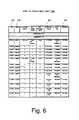
- FIG. 6illustrates a service group map table.
- a service group map table 600is sent from the system controller 44 (shown in FIG. 2 ) to the HCTs.
- the service group map table 600includes a listing of TSIDs 602 , SGIDs 604 , modulation formats 606 , and frequencies 608 an HCT uses to determine an associated service group.
- a frequencysuch as 506 MHz, may be listed multiple times in the table since the subscriber television system may reuse frequencies for different purposes in different services groups.
- An HCTcan retrieve the table and determine its service group based on the retrieved TSIDs (e.g., 0x0031 or 0x0531).
- the modulation format 606 fieldallows for multiple types of modulators within the subscriber television system, such as 64 QAM and 256 QAM modulators.
- FIG. 7illustrates a method for dynamically determining the service group associated with an HCT.
- the HCT service group association method 700can be programmed to occur at various times, such as during initialization of the HCT when first installed in a system, upon receiving a system command to check its service group, and periodically upon HCT activation (e.g., power on).
- HCTbegins by retrieving a service group map table 600 from the appropriate MPEG transport stream (step 705 ).
- Each frequency listed in the service group map table 600is associated with a service group.
- the HCTtunes to a first frequency from the table 600 (step 706 ).
- the frequencies 608are tuned in ascending order based on the assignment of the lowest frequencies to modulators in the lowest service group level (i.e., Level 0). This prevents the HCT from incorrectly determining its service group by tuning to a modulator associated frequency at a higher service group level before it checks for a lower level association.
- the HCTchecks at the tuned frequency for a valid signal or MPEG bit stream (step 707 ).
- the HCTin step 708 , will read the TSID 602 of the MPEG bit stream and find the associated service group 604 from the table 600 retrieved in step 705 . If, in step 709 , the associated service group 604 is determined to be the same service group association previously stored on the HCT, method 700 stops (step 710 ). If, in step 709 , the associated service group 604 is determined to be different from the service group association previously stored on the HCT, the HCT will transmit the associated service group 604 to the system controller (step 711 ). If the HCT does not find a valid signal at the tuned frequency in step 707 , the HCT tunes to the next frequency from the table 600 (step 706 ).
- HCTs 501 , 502 , and 510would retrieve service group map table 600 from the appropriate transport stream (step 705 ) and tune to the lowest frequency of 506 MHz (step 706 ).
- HCTs 501 and 502would find a valid signal (step 707 ).
- HCT 510would repeat steps 706 and 707 for frequencies 506 MHz, 512 MHz, 518 MHz, 524 MHz, and 752 MHz.
- the frequencies 608 from table 600include a mix of modulation formats 606 .
- a subscriber television system network 100may use different modulation formats depending on the placement of the modulators within the network. Typically, the 64 QAM modulation format would be associated with a location further from the headend in the network and therefor associated with a lower service group level.
- the two 752 MHz frequency listings in table 600include one modulation format of 64 QAM and one of 256 QAM.
- the HCTwould first try to tune to this frequency using the 64 QAM modulation format parameters. If it was unable to lock onto a QAM carrier, the HCT would then try to tune to 752 MHz using the 256 QAM modulation format parameters.
- HCT 510finds a valid signal at 764 MHz with a 256 QAM modulation format.
- the HCTs 501 , 502 , and 510In response to a request for service group association or if the associated service group was different then a previously stored service group association, the HCTs 501 , 502 , and 510 would transmit their respective service group associations to the control system 44 (shown in FIG. 2 ) of the subscriber television network (step 711 ).
- the control system 44(shown in FIG. 2 ) of the subscriber television network maintains a database of the service group associated with each HCT. From this database the control system 44 can determine what services and programming are available on a particular HCT.
- the service group association method 700allows the dynamic updating of a database to keep it current as to the services and programming available to the HCTs.
- the subscriber television system layoutremains fairly static and is only occasionally reconfigured or changed with the addition, replacement, or removal of components.
- the system controllermaintains a service group database of the relationships of the service groups to the various components within the system, such as modulators, combiners, servers, and nodes. To keep the database current the system controller will perform a service group audit. This occurs periodically and upon layout or configuration changes.
- a modulator tuning table 800 associated with the service group auditis maintained by the system controller.
- FIG. 8illustrates a modulator tuning table.
- the modulator tuning table 800would be sent in the transport streams to HCTs that will be involved in the audit.
- the modulator tuning table 800includes a complete listing of frequencies 802 and modulation formats 804 available in the subscriber television system.
- the modulation format 804 fieldallows for multiple types of modulation formats at the same frequency, such as 64 QAM and 256 QAM modulation at 752 MHz.
- a modulatorWhen a modulator is physically installed in the subscriber television system, it is connected to a combiner, such as combiner 46 (shown in FIG. 2 ).
- the location of the combiners in the networkare associated with the service group assignments and levels.
- the system controllerqueries various network components to discover their location in the network and their relationships to other components. Because the combiner 46 is typically a passive device, the system controller cannot directly query it to determine which modulators the combiner 46 combines to provide services to a particular service group. Consequently, a designated HCT associated with a service group is required to periodically execute a service group audit to provide the information. In a service group audit, the designated HCT tunes to every frequency available in the subscriber television system.
- a subscriber HCT or other equipmentcan be a designated audit device.
- the system operatordefines the service groups and designates a device to audit that service group.
- a device that is designated to audit a service groupmust be connected to a point beyond a service group combiner but before any other combiners. That is, all system input to the audit device must come directly from the output of the combiner that it is designated to audit.
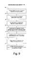
- FIG. 9illustrates a method for the discovery and establishment of service groups within a subscriber television system through the use of service group audits.
- the method 900begins at step 902 when the system controller detects that the modulator configuration has been modified. The method then proceeds to step 902 where the system controller rebuilds the modulator tuning table 800 that contains the tuning information for all modulators in the system.
- the system controllerthen sends an audit request to each of the designated service group audit HCTs (step 906 ). This request causes these HCTs to perform a service group audit.
- Each of the designated HCTsretrieves the modulator tuning table from the bit stream and attempts to tune every listed modulator frequency (step 908 ). When a valid modulator signal is found, the HCT records its TSID (step 910 ).
- the HCTsends a list of the TSIDs that it found to the system controller (step 912 ).
- the system controlleruses this report to document the topology of TSIDs and service groups and to maintain the database of those associations (step 914 ).
- the information on the relationships between the components of a subscriber television system and the service groups and service group levelsmay be contained within a single database or within multiple databases.
- the service group audit method 900in conjunction with system operator input, is used during the initialization of a system to establish the service groups and service group levels.
- the periodic updating of the modulator tuning table 800 and the various databasesensure that the table and databases accurately reflect the current configuration of the subscriber television system.
- System controller auditingprovides an updating to service group association and levels whenever any component changes or any portion of or all of the system is reconfigured.
- the present inventionis directed to a method, apparatus, and system that allows the easy and dynamic identification of the services and programming available to an HCT within a subscriber television system.
- the HCTdetermines and informs the subscriber television system of the service group that it belongs to.
- the present inventionis also directed to a method and apparatus for establishing service groups and service group associations within a subscriber television system using service group audits.
- the service group auditis used to define and update the service groups of the digital subscriber television system.
- the present inventionhas been described in relation to particular embodiments, which are intended in all respects to be illustrative rather than restrictive. For example, there are methods known to those skilled in the art of designing subscriber television systems of using other modulation and routing schemes for both in-band and out-of-band communications and data transmission other than a QAM and QPSK combination. There are system designs that use only QAM modulation and that utilize other communication routing methods.
- the service group associations of the present inventionare not limited to a particular modulation scheme.
- the foregoing descriptionincludes a decoder 110 , typically an HCT.
- a decoder 110typically an HCT.
- the functionality of the HCT associated with the present inventioncan be consolidated to single card that can be located in any of a number of devices, such as a TV, computer, or even a portable device. The portable device could be used in conjunction with any of the other devices.
- the functionality associated with creating tables, retrieving tables from a transport stream, tuning to a frequency, transmitting and receiving messages within a subscriber television system, and establishing, updating, and maintaining databasescan be achieved by a variety of methods well known in the related arts.
- the present inventionis not so limited and can be employed to determine a service group association of any equipment capable of two-way communication and receiving services and programming within a subscriber television system.
Landscapes
- Engineering & Computer Science (AREA)
- Multimedia (AREA)
- Signal Processing (AREA)
- Databases & Information Systems (AREA)
- Physics & Mathematics (AREA)
- Astronomy & Astrophysics (AREA)
- General Physics & Mathematics (AREA)
- Computer Security & Cryptography (AREA)
- Computer Graphics (AREA)
- General Engineering & Computer Science (AREA)
- Software Systems (AREA)
- Two-Way Televisions, Distribution Of Moving Picture Or The Like (AREA)
Abstract
Description
Claims (17)
Priority Applications (2)
| Application Number | Priority Date | Filing Date | Title |
|---|---|---|---|
| US09/592,405US7246366B1 (en) | 2000-06-13 | 2000-06-13 | System and method for automatically determining service groups in a subscriber network |
| PCT/US2001/018827WO2001097507A2 (en) | 2000-06-13 | 2001-06-12 | System and method for automatically determining service groups in a subscriber network |
Applications Claiming Priority (1)
| Application Number | Priority Date | Filing Date | Title |
|---|---|---|---|
| US09/592,405US7246366B1 (en) | 2000-06-13 | 2000-06-13 | System and method for automatically determining service groups in a subscriber network |
Publications (1)
| Publication Number | Publication Date |
|---|---|
| US7246366B1true US7246366B1 (en) | 2007-07-17 |
Family
ID=24370515
Family Applications (1)
| Application Number | Title | Priority Date | Filing Date |
|---|---|---|---|
| US09/592,405Expired - LifetimeUS7246366B1 (en) | 2000-06-13 | 2000-06-13 | System and method for automatically determining service groups in a subscriber network |
Country Status (2)
| Country | Link |
|---|---|
| US (1) | US7246366B1 (en) |
| WO (1) | WO2001097507A2 (en) |
Cited By (33)
| Publication number | Priority date | Publication date | Assignee | Title |
|---|---|---|---|---|
| US20020007491A1 (en)* | 2000-01-13 | 2002-01-17 | Schiller Jay B. | Method and apparatus for identifying a signal route for delivery of video-on-demand to a subscriber terminal |
| US20050251845A1 (en)* | 2004-05-04 | 2005-11-10 | Mcdowell Ronald W | Method for quickly identifying network session resources |
| US20050249130A1 (en)* | 2004-05-04 | 2005-11-10 | Schutte Mark E | Method for searching ordered entries in a service group map to facilitate auto channel discovery |
| US20050251837A1 (en)* | 2004-05-04 | 2005-11-10 | Mcdowell Ronald W | Method of prioritizing entries within a service group map to facilitate auto channel discovery |
| US20060248464A1 (en)* | 2005-04-27 | 2006-11-02 | Comcast Cable Holdings, Llc | Method and system of transporting media signals and allocating assets |
| US20070067817A1 (en)* | 2005-09-20 | 2007-03-22 | International Business Machines Corporation | Topology based proximity validation for broadcast content |
| US20070083900A1 (en)* | 2005-10-10 | 2007-04-12 | Lg Electronics Inc. Ltd | Apparatus and method for providing VOD service |
| US20070261089A1 (en)* | 2003-11-13 | 2007-11-08 | Cliff Aaby | System to Provide Set Top Box Configuration for Content on Demand |
| US20080219277A1 (en)* | 2007-03-06 | 2008-09-11 | Cisco Technology, Inc | Modelling service flows in dynamic access domains |
| US7471639B1 (en)* | 2003-01-23 | 2008-12-30 | Michael Bauer | Method and system for modulating media packets |
| US20090133084A1 (en)* | 2007-11-16 | 2009-05-21 | Time Warner Cable Inc. | Apparatus and method for providing video content and supplemental information to a client over a switched digital video content-based network |
| US20090158380A1 (en)* | 2007-12-12 | 2009-06-18 | General Instrument Corporation | Set top terminal performing service group number autodiscovery during initialization or boot-up process |
| US20090291277A1 (en)* | 2008-05-15 | 2009-11-26 | Thomas Chirayil | Method of Making Thin Film Structures and Compositions thereof |
| US20110053623A1 (en)* | 2009-09-03 | 2011-03-03 | Cisco Technology, Inc. | Hfc banding for a virtual service group |
| US20110131625A1 (en)* | 2009-12-01 | 2011-06-02 | John Schlack | Dynamic service group discovery |
| US20150046960A1 (en)* | 2004-06-29 | 2015-02-12 | Time Warner Cable Enterprises Llc | Method and apparatus for network bandwidth allocation |
| US9584839B2 (en) | 2007-10-15 | 2017-02-28 | Time Warner Cable Enterprises Llc | Methods and apparatus for revenue-optimized delivery of content in a network |
| US9883223B2 (en) | 2012-12-14 | 2018-01-30 | Time Warner Cable Enterprises Llc | Apparatus and methods for multimedia coordination |
| US9930387B2 (en) | 2005-02-01 | 2018-03-27 | Time Warner Cable Enterprises Llc | Method and apparatus for network bandwidth conservation |
| US9961383B2 (en) | 2008-02-26 | 2018-05-01 | Time Warner Cable Enterprises Llc | Methods and apparatus for business-based network resource allocation |
| US10009652B2 (en) | 2006-02-27 | 2018-06-26 | Time Warner Cable Enterprises Llc | Methods and apparatus for selecting digital access technology for programming and data delivery |
| US10051302B2 (en) | 2006-02-27 | 2018-08-14 | Time Warner Cable Enterprises Llc | Methods and apparatus for device capabilities discovery and utilization within a content distribution network |
| US10085047B2 (en) | 2007-09-26 | 2018-09-25 | Time Warner Cable Enterprises Llc | Methods and apparatus for content caching in a video network |
| US10225592B2 (en) | 2007-03-20 | 2019-03-05 | Time Warner Cable Enterprises Llc | Methods and apparatus for content delivery and replacement in a network |
| US10223713B2 (en) | 2007-09-26 | 2019-03-05 | Time Warner Cable Enterprises Llc | Methods and apparatus for user-based targeted content delivery |
| US10637740B2 (en)* | 2017-07-07 | 2020-04-28 | Howard Pfeffer | Apparatus and methods for management, configuration and provisioning of communication devices in a distributed access architecture |
| US10687115B2 (en) | 2016-06-01 | 2020-06-16 | Time Warner Cable Enterprises Llc | Cloud-based digital content recorder apparatus and methods |
| US10764651B1 (en)* | 2016-12-16 | 2020-09-01 | CSC Holdings, LLC | Service group discovery |
| US10911794B2 (en) | 2016-11-09 | 2021-02-02 | Charter Communications Operating, Llc | Apparatus and methods for selective secondary content insertion in a digital network |
| US10939142B2 (en) | 2018-02-27 | 2021-03-02 | Charter Communications Operating, Llc | Apparatus and methods for content storage, distribution and security within a content distribution network |
| US10965727B2 (en) | 2009-06-08 | 2021-03-30 | Time Warner Cable Enterprises Llc | Methods and apparatus for premises content distribution |
| US11496782B2 (en) | 2012-07-10 | 2022-11-08 | Time Warner Cable Enterprises Llc | Apparatus and methods for selective enforcement of secondary content viewing |
| US11722938B2 (en) | 2017-08-04 | 2023-08-08 | Charter Communications Operating, Llc | Switching connections over frequency bands of a wireless network |
Families Citing this family (1)
| Publication number | Priority date | Publication date | Assignee | Title |
|---|---|---|---|---|
| US20040158867A1 (en)* | 2003-02-10 | 2004-08-12 | General Instrument Corporation | Methods, systems, and apparatus for determining transport stream channels for video-on-demand applications |
Citations (29)
| Publication number | Priority date | Publication date | Assignee | Title |
|---|---|---|---|---|
| US4860379A (en) | 1979-05-18 | 1989-08-22 | General Instrument Corporation | Data communications system |
| US5255086A (en) | 1990-03-20 | 1993-10-19 | Scientific-Atlanta, Inc. | Method and apparatus for RF data transfer in a CATV system |
| EP0725549A2 (en) | 1995-02-02 | 1996-08-07 | Hitachi Denshi Kabushiki Kaisha | Group-calls in a multi-channel access communication system |
| US5805230A (en)* | 1994-03-01 | 1998-09-08 | Thomson Multimedia | Method for automatic programming of a tuner and device for implementation of the method |
| US5838383A (en)* | 1994-08-31 | 1998-11-17 | Kabushiki Kaisha Toshiba | Multimedia television receiver and method of booting the same |
| US5940509A (en)* | 1995-06-30 | 1999-08-17 | Intermec Ip Corp. | Method and apparatus for controlling country specific frequency allocation |
| US5953051A (en) | 1997-08-01 | 1999-09-14 | International Business Machines Corporation | Method and apparatus for controlling access in a video distribution network |
| US5953506A (en)* | 1996-12-17 | 1999-09-14 | Adaptive Media Technologies | Method and apparatus that provides a scalable media delivery system |
| US6035339A (en)* | 1997-03-13 | 2000-03-07 | At&T Corporation | Network information delivery system for delivering information based on end user terminal requirements |
| US6167441A (en)* | 1997-11-21 | 2000-12-26 | International Business Machines Corporation | Customization of web pages based on requester type |
| US6172674B1 (en)* | 1997-08-25 | 2001-01-09 | Liberate Technologies | Smart filtering |
| US6177931B1 (en)* | 1996-12-19 | 2001-01-23 | Index Systems, Inc. | Systems and methods for displaying and recording control interface with television programs, video, advertising information and program scheduling information |
| US6289358B1 (en)* | 1998-04-15 | 2001-09-11 | Inktomi Corporation | Delivering alternate versions of objects from an object cache |
| US6340997B1 (en)* | 1998-04-08 | 2002-01-22 | Microsoft Corporation | Worldwide television tuning system with object-based tuning control modules |
| US20020027562A1 (en)* | 2000-02-03 | 2002-03-07 | Kimble David Michael | Web browser plug-in for TV |
| US6366326B1 (en)* | 1996-08-01 | 2002-04-02 | Thomson Consumer Electronics Inc. | System for acquiring, processing, and storing video data and program guides transmitted in different coding formats |
| US6401242B1 (en)* | 1997-10-24 | 2002-06-04 | General Instrument Corporation | Method and apparatus for designating a preferred source to avoid duplicative programming services |
| US6415437B1 (en)* | 1998-07-23 | 2002-07-02 | Diva Systems Corporation | Method and apparatus for combining video sequences with an interactive program guide |
| US6421726B1 (en)* | 1997-03-14 | 2002-07-16 | Akamai Technologies, Inc. | System and method for selection and retrieval of diverse types of video data on a computer network |
| US6484029B2 (en)* | 1998-10-13 | 2002-11-19 | Symbol Technologies, Inc. | Apparatus and methods for adapting mobile unit to wireless LAN |
| US6513112B1 (en)* | 1999-07-26 | 2003-01-28 | Microsoft Corporation | System and apparatus for administration of configuration information using a catalog server object to describe and manage requested configuration information to be stored in a table object |
| US6594699B1 (en)* | 1997-10-10 | 2003-07-15 | Kasenna, Inc. | System for capability based multimedia streaming over a network |
| US6622303B1 (en)* | 1999-02-19 | 2003-09-16 | Sony Corporation | Digital broadcast transmitting method and digital broadcast transmitting apparatus |
| US6647389B1 (en)* | 1999-08-30 | 2003-11-11 | 3Com Corporation | Search engine to verify streaming audio sources |
| US6704930B1 (en)* | 1999-04-20 | 2004-03-09 | Expanse Networks, Inc. | Advertisement insertion techniques for digital video streams |
| US6718374B1 (en)* | 1999-04-21 | 2004-04-06 | General Instrument Corporation | Method and system for identifying and downloading appropriate software or formware specific to a particular model of set-top box in a cable television system |
| US6734804B1 (en)* | 1996-07-08 | 2004-05-11 | Lg Electronics Inc. | Automatic channel memory and selection method for a television set |
| US6757912B1 (en)* | 1997-03-31 | 2004-06-29 | Hewlett-Packard Development Company, L.P. | Channel server functionality |
| US7042526B1 (en)* | 1998-04-08 | 2006-05-09 | Microsoft Corporation | Worldwide television tuning system with country code based tuning |
- 2000
- 2000-06-13USUS09/592,405patent/US7246366B1/ennot_activeExpired - Lifetime
- 2001
- 2001-06-12WOPCT/US2001/018827patent/WO2001097507A2/enactiveApplication Filing
Patent Citations (29)
| Publication number | Priority date | Publication date | Assignee | Title |
|---|---|---|---|---|
| US4860379A (en) | 1979-05-18 | 1989-08-22 | General Instrument Corporation | Data communications system |
| US5255086A (en) | 1990-03-20 | 1993-10-19 | Scientific-Atlanta, Inc. | Method and apparatus for RF data transfer in a CATV system |
| US5805230A (en)* | 1994-03-01 | 1998-09-08 | Thomson Multimedia | Method for automatic programming of a tuner and device for implementation of the method |
| US5838383A (en)* | 1994-08-31 | 1998-11-17 | Kabushiki Kaisha Toshiba | Multimedia television receiver and method of booting the same |
| EP0725549A2 (en) | 1995-02-02 | 1996-08-07 | Hitachi Denshi Kabushiki Kaisha | Group-calls in a multi-channel access communication system |
| US5940509A (en)* | 1995-06-30 | 1999-08-17 | Intermec Ip Corp. | Method and apparatus for controlling country specific frequency allocation |
| US6734804B1 (en)* | 1996-07-08 | 2004-05-11 | Lg Electronics Inc. | Automatic channel memory and selection method for a television set |
| US6366326B1 (en)* | 1996-08-01 | 2002-04-02 | Thomson Consumer Electronics Inc. | System for acquiring, processing, and storing video data and program guides transmitted in different coding formats |
| US5953506A (en)* | 1996-12-17 | 1999-09-14 | Adaptive Media Technologies | Method and apparatus that provides a scalable media delivery system |
| US6177931B1 (en)* | 1996-12-19 | 2001-01-23 | Index Systems, Inc. | Systems and methods for displaying and recording control interface with television programs, video, advertising information and program scheduling information |
| US6035339A (en)* | 1997-03-13 | 2000-03-07 | At&T Corporation | Network information delivery system for delivering information based on end user terminal requirements |
| US6421726B1 (en)* | 1997-03-14 | 2002-07-16 | Akamai Technologies, Inc. | System and method for selection and retrieval of diverse types of video data on a computer network |
| US6757912B1 (en)* | 1997-03-31 | 2004-06-29 | Hewlett-Packard Development Company, L.P. | Channel server functionality |
| US5953051A (en) | 1997-08-01 | 1999-09-14 | International Business Machines Corporation | Method and apparatus for controlling access in a video distribution network |
| US6172674B1 (en)* | 1997-08-25 | 2001-01-09 | Liberate Technologies | Smart filtering |
| US6594699B1 (en)* | 1997-10-10 | 2003-07-15 | Kasenna, Inc. | System for capability based multimedia streaming over a network |
| US6401242B1 (en)* | 1997-10-24 | 2002-06-04 | General Instrument Corporation | Method and apparatus for designating a preferred source to avoid duplicative programming services |
| US6167441A (en)* | 1997-11-21 | 2000-12-26 | International Business Machines Corporation | Customization of web pages based on requester type |
| US7042526B1 (en)* | 1998-04-08 | 2006-05-09 | Microsoft Corporation | Worldwide television tuning system with country code based tuning |
| US6340997B1 (en)* | 1998-04-08 | 2002-01-22 | Microsoft Corporation | Worldwide television tuning system with object-based tuning control modules |
| US6289358B1 (en)* | 1998-04-15 | 2001-09-11 | Inktomi Corporation | Delivering alternate versions of objects from an object cache |
| US6415437B1 (en)* | 1998-07-23 | 2002-07-02 | Diva Systems Corporation | Method and apparatus for combining video sequences with an interactive program guide |
| US6484029B2 (en)* | 1998-10-13 | 2002-11-19 | Symbol Technologies, Inc. | Apparatus and methods for adapting mobile unit to wireless LAN |
| US6622303B1 (en)* | 1999-02-19 | 2003-09-16 | Sony Corporation | Digital broadcast transmitting method and digital broadcast transmitting apparatus |
| US6704930B1 (en)* | 1999-04-20 | 2004-03-09 | Expanse Networks, Inc. | Advertisement insertion techniques for digital video streams |
| US6718374B1 (en)* | 1999-04-21 | 2004-04-06 | General Instrument Corporation | Method and system for identifying and downloading appropriate software or formware specific to a particular model of set-top box in a cable television system |
| US6513112B1 (en)* | 1999-07-26 | 2003-01-28 | Microsoft Corporation | System and apparatus for administration of configuration information using a catalog server object to describe and manage requested configuration information to be stored in a table object |
| US6647389B1 (en)* | 1999-08-30 | 2003-11-11 | 3Com Corporation | Search engine to verify streaming audio sources |
| US20020027562A1 (en)* | 2000-02-03 | 2002-03-07 | Kimble David Michael | Web browser plug-in for TV |
Cited By (57)
| Publication number | Priority date | Publication date | Assignee | Title |
|---|---|---|---|---|
| US9100703B2 (en)* | 2000-01-13 | 2015-08-04 | Arris Solutions, Inc. | Identifying a signal route for delivery of video-on-demand to a subscriber terminal |
| US8418214B2 (en)* | 2000-01-13 | 2013-04-09 | Arris Group, Inc. | Method and apparatus for identifying a signal route for delivery of video-on-demand to a subscriber terminal |
| US20020007491A1 (en)* | 2000-01-13 | 2002-01-17 | Schiller Jay B. | Method and apparatus for identifying a signal route for delivery of video-on-demand to a subscriber terminal |
| US20130227623A1 (en)* | 2000-01-13 | 2013-08-29 | Broadband Royalty Corporation | identifying a signal route for delivery of video-on-demand to a subscriber terminal |
| US9781480B2 (en)* | 2000-01-13 | 2017-10-03 | Arris Enterprises Llc | Method and apparatus for identifying a signal route for delivery of video-on-demand to a subscriber terminal |
| US20150334427A1 (en)* | 2000-01-13 | 2015-11-19 | Arris Solutions, Inc. | Method and apparatus for identifying a signal route for delivery of video-on-demand to a subscriber terminal |
| US7471639B1 (en)* | 2003-01-23 | 2008-12-30 | Michael Bauer | Method and system for modulating media packets |
| US20070261089A1 (en)* | 2003-11-13 | 2007-11-08 | Cliff Aaby | System to Provide Set Top Box Configuration for Content on Demand |
| US8146123B2 (en)* | 2003-11-13 | 2012-03-27 | Arris Group, Inc. | System to provide set top box configuration for content on demand |
| US20050251837A1 (en)* | 2004-05-04 | 2005-11-10 | Mcdowell Ronald W | Method of prioritizing entries within a service group map to facilitate auto channel discovery |
| US20050249130A1 (en)* | 2004-05-04 | 2005-11-10 | Schutte Mark E | Method for searching ordered entries in a service group map to facilitate auto channel discovery |
| US7530092B2 (en) | 2004-05-04 | 2009-05-05 | Scientific-Atlanta, Inc. | Method of prioritizing entries within a service group map to facilitate auto channel discovery |
| US20050251845A1 (en)* | 2004-05-04 | 2005-11-10 | Mcdowell Ronald W | Method for quickly identifying network session resources |
| US20150046960A1 (en)* | 2004-06-29 | 2015-02-12 | Time Warner Cable Enterprises Llc | Method and apparatus for network bandwidth allocation |
| US9578355B2 (en)* | 2004-06-29 | 2017-02-21 | Time Warner Cable Enterprises Llc | Method and apparatus for network bandwidth allocation |
| US9930387B2 (en) | 2005-02-01 | 2018-03-27 | Time Warner Cable Enterprises Llc | Method and apparatus for network bandwidth conservation |
| US8214465B2 (en)* | 2005-04-27 | 2012-07-03 | Comcast Cable Holdings, Llc | Method and system of transporting media signals and allocating assets |
| US20060248464A1 (en)* | 2005-04-27 | 2006-11-02 | Comcast Cable Holdings, Llc | Method and system of transporting media signals and allocating assets |
| US20070067817A1 (en)* | 2005-09-20 | 2007-03-22 | International Business Machines Corporation | Topology based proximity validation for broadcast content |
| US7530088B2 (en)* | 2005-09-20 | 2009-05-05 | International Business Machines Corporation | Topology based proximity validation for broadcast content |
| US20070083900A1 (en)* | 2005-10-10 | 2007-04-12 | Lg Electronics Inc. Ltd | Apparatus and method for providing VOD service |
| US10009652B2 (en) | 2006-02-27 | 2018-06-26 | Time Warner Cable Enterprises Llc | Methods and apparatus for selecting digital access technology for programming and data delivery |
| US10743066B2 (en) | 2006-02-27 | 2020-08-11 | Time Warner Cable Enterprises Llc | Methods and apparatus for selecting digital access technology for programming and data delivery |
| US10051302B2 (en) | 2006-02-27 | 2018-08-14 | Time Warner Cable Enterprises Llc | Methods and apparatus for device capabilities discovery and utilization within a content distribution network |
| US8040820B2 (en)* | 2007-03-06 | 2011-10-18 | Cisco Technology, Inc. | Modelling service flows in dynamic access domains |
| US20080219277A1 (en)* | 2007-03-06 | 2008-09-11 | Cisco Technology, Inc | Modelling service flows in dynamic access domains |
| US10225592B2 (en) | 2007-03-20 | 2019-03-05 | Time Warner Cable Enterprises Llc | Methods and apparatus for content delivery and replacement in a network |
| US10863220B2 (en) | 2007-03-20 | 2020-12-08 | Time Warner Cable Enterprises Llc | Methods and apparatus for content delivery and replacement in a network |
| US10223713B2 (en) | 2007-09-26 | 2019-03-05 | Time Warner Cable Enterprises Llc | Methods and apparatus for user-based targeted content delivery |
| US10085047B2 (en) | 2007-09-26 | 2018-09-25 | Time Warner Cable Enterprises Llc | Methods and apparatus for content caching in a video network |
| US10810628B2 (en) | 2007-09-26 | 2020-10-20 | Time Warner Cable Enterprises Llc | Methods and apparatus for user-based targeted content delivery |
| US9584839B2 (en) | 2007-10-15 | 2017-02-28 | Time Warner Cable Enterprises Llc | Methods and apparatus for revenue-optimized delivery of content in a network |
| US11223860B2 (en) | 2007-10-15 | 2022-01-11 | Time Warner Cable Enterprises Llc | Methods and apparatus for revenue-optimized delivery of content in a network |
| US20090133084A1 (en)* | 2007-11-16 | 2009-05-21 | Time Warner Cable Inc. | Apparatus and method for providing video content and supplemental information to a client over a switched digital video content-based network |
| US8146129B2 (en)* | 2007-11-16 | 2012-03-27 | Time Warner Cable Inc. | Apparatus and method for providing video content and supplemental information to a client over a switched digital video content-based network |
| US20090158380A1 (en)* | 2007-12-12 | 2009-06-18 | General Instrument Corporation | Set top terminal performing service group number autodiscovery during initialization or boot-up process |
| US8499327B2 (en)* | 2007-12-12 | 2013-07-30 | General Instrument Corporation | Set top terminal performing service group number autodiscovery during initialization or boot-up process |
| US9961383B2 (en) | 2008-02-26 | 2018-05-01 | Time Warner Cable Enterprises Llc | Methods and apparatus for business-based network resource allocation |
| US20090291277A1 (en)* | 2008-05-15 | 2009-11-26 | Thomas Chirayil | Method of Making Thin Film Structures and Compositions thereof |
| US8916234B2 (en) | 2008-05-15 | 2014-12-23 | Basf Corporation | Method of making thin film structures and compositions thereof |
| US20100136235A1 (en)* | 2008-05-15 | 2010-06-03 | Thomas Chirayil | Method of Making Thin Film Structures and Compositions Thereof |
| US10965727B2 (en) | 2009-06-08 | 2021-03-30 | Time Warner Cable Enterprises Llc | Methods and apparatus for premises content distribution |
| US20110053623A1 (en)* | 2009-09-03 | 2011-03-03 | Cisco Technology, Inc. | Hfc banding for a virtual service group |
| US20110131625A1 (en)* | 2009-12-01 | 2011-06-02 | John Schlack | Dynamic service group discovery |
| US8671436B2 (en)* | 2009-12-01 | 2014-03-11 | Beaumaris Networks Inc. | Dynamic service group discovery |
| US11496782B2 (en) | 2012-07-10 | 2022-11-08 | Time Warner Cable Enterprises Llc | Apparatus and methods for selective enforcement of secondary content viewing |
| US9883223B2 (en) | 2012-12-14 | 2018-01-30 | Time Warner Cable Enterprises Llc | Apparatus and methods for multimedia coordination |
| US10687115B2 (en) | 2016-06-01 | 2020-06-16 | Time Warner Cable Enterprises Llc | Cloud-based digital content recorder apparatus and methods |
| US11695994B2 (en) | 2016-06-01 | 2023-07-04 | Time Warner Cable Enterprises Llc | Cloud-based digital content recorder apparatus and methods |
| US10911794B2 (en) | 2016-11-09 | 2021-02-02 | Charter Communications Operating, Llc | Apparatus and methods for selective secondary content insertion in a digital network |
| US11973992B2 (en) | 2016-11-09 | 2024-04-30 | Charter Communications Operating, Llc | Apparatus and methods for selective secondary content insertion in a digital network |
| US10764651B1 (en)* | 2016-12-16 | 2020-09-01 | CSC Holdings, LLC | Service group discovery |
| US10637740B2 (en)* | 2017-07-07 | 2020-04-28 | Howard Pfeffer | Apparatus and methods for management, configuration and provisioning of communication devices in a distributed access architecture |
| US11722938B2 (en) | 2017-08-04 | 2023-08-08 | Charter Communications Operating, Llc | Switching connections over frequency bands of a wireless network |
| US10939142B2 (en) | 2018-02-27 | 2021-03-02 | Charter Communications Operating, Llc | Apparatus and methods for content storage, distribution and security within a content distribution network |
| US11553217B2 (en) | 2018-02-27 | 2023-01-10 | Charter Communications Operating, Llc | Apparatus and methods for content storage, distribution and security within a content distribution network |
| US12081808B2 (en) | 2018-02-27 | 2024-09-03 | Charter Communications Operating, Llc | Apparatus and methods for content storage, distribution and security within a content distribution network |
Also Published As
| Publication number | Publication date |
|---|---|
| WO2001097507A2 (en) | 2001-12-20 |
| WO2001097507A3 (en) | 2002-05-23 |
Similar Documents
| Publication | Publication Date | Title |
|---|---|---|
| US7246366B1 (en) | System and method for automatically determining service groups in a subscriber network | |
| US9781480B2 (en) | Method and apparatus for identifying a signal route for delivery of video-on-demand to a subscriber terminal | |
| US6378130B1 (en) | Media server interconnect architecture | |
| US6697376B1 (en) | Logical node identification in an information transmission network | |
| US9479806B2 (en) | Methods and apparatus for implementing guides and using recording information in determining program to communications channel mappings | |
| US6738983B1 (en) | Video pedestal network | |
| US6240553B1 (en) | Method for providing scalable in-band and out-of-band access within a video-on-demand environment | |
| CA2313846C (en) | Television advertisement delivery system and method | |
| US20020154892A1 (en) | System for distributing video and content on demand | |
| US20080244667A1 (en) | Bandwidth sensitive switched digital video content delivery | |
| US20080216136A1 (en) | Methods and apparatus supporting the recording of multiple simultaneously broadcast programs communicated using the same communications channel | |
| US20030051251A1 (en) | System and apparatus for supplying audiovisual information to a subscriber terminal | |
| US20040226044A1 (en) | Network bandwidth optimization by dynamic channel allocation | |
| US20080216135A1 (en) | Methods and apparatus for improved content delivery including content delivery streams dynamically populated in response to user requests | |
| US20030051250A1 (en) | Arrangement for supplying audiovisual information to a subscriber terminal | |
| US20040158867A1 (en) | Methods, systems, and apparatus for determining transport stream channels for video-on-demand applications | |
| US20060271985A1 (en) | Peripheral unit for upstream cable television system communication | |
| US20110053623A1 (en) | Hfc banding for a virtual service group | |
| US20070061854A1 (en) | Apparatus, system and method for the transmission of a dynamic bandwidth signal across a catv network | |
| US7787439B1 (en) | Method and systems for providing enhanced television services | |
| KR101419818B1 (en) | Driving system and method for iptv cable modem capable of realtime viewing for several channel | |
| JP2024080776A (en) | Video content distribution system | |
| HK1055871A (en) | Method and apparatus for identifying a signal route for delivery of video-on-demand to a subscriber terminal |
Legal Events
| Date | Code | Title | Description |
|---|---|---|---|
| AS | Assignment | Owner name:SCIENTIFIC-ATLANTA, INC., GEORGIA Free format text:ASSIGNMENT OF ASSIGNORS INTEREST;ASSIGNORS:ADDINGTON, TIMOTHY H.;O'CARROLL, GERALD H., JR.;BEEBE, RANDOLPH R.;REEL/FRAME:010897/0434;SIGNING DATES FROM 20000608 TO 20000612 | |
| STCF | Information on status: patent grant | Free format text:PATENTED CASE | |
| FPAY | Fee payment | Year of fee payment:4 | |
| AS | Assignment | Owner name:SCIENTIFIC-ATLANTA, LLC, GEORGIA Free format text:CHANGE OF NAME;ASSIGNOR:SCIENTIFIC-ATLANTA, INC.;REEL/FRAME:034299/0440 Effective date:20081205 Owner name:CISCO TECHNOLOGY, INC., CALIFORNIA Free format text:ASSIGNMENT OF ASSIGNORS INTEREST;ASSIGNOR:SCIENTIFIC-ATLANTA, LLC;REEL/FRAME:034300/0001 Effective date:20141118 | |
| FPAY | Fee payment | Year of fee payment:8 | |
| AS | Assignment | Owner name:NDS LIMITED, UNITED KINGDOM Free format text:ASSIGNMENT OF ASSIGNORS INTEREST;ASSIGNORS:BEAUMARIS NETWORKS LLC;CISCO SYSTEMS INTERNATIONAL S.A.R.L.;CISCO TECHNOLOGY, INC.;AND OTHERS;REEL/FRAME:047420/0600 Effective date:20181028 | |
| AS | Assignment | Owner name:SYNAMEDIA LIMITED, UNITED KINGDOM Free format text:CHANGE OF NAME;ASSIGNOR:NDS LIMITED;REEL/FRAME:048172/0917 Effective date:20181108 | |
| FEPP | Fee payment procedure | Free format text:11.5 YR SURCHARGE- LATE PMT W/IN 6 MO, LARGE ENTITY (ORIGINAL EVENT CODE: M1556); ENTITY STATUS OF PATENT OWNER: LARGE ENTITY | |
| MAFP | Maintenance fee payment | Free format text:PAYMENT OF MAINTENANCE FEE, 12TH YEAR, LARGE ENTITY (ORIGINAL EVENT CODE: M1553); ENTITY STATUS OF PATENT OWNER: LARGE ENTITY Year of fee payment:12 |