US7246037B2 - Methods and apparatus for an improved signal monitor - Google Patents
Methods and apparatus for an improved signal monitorDownload PDFInfo
- Publication number
- US7246037B2 US7246037B2US11/184,418US18441805AUS7246037B2US 7246037 B2US7246037 B2US 7246037B2US 18441805 AUS18441805 AUS 18441805AUS 7246037 B2US7246037 B2US 7246037B2
- Authority
- US
- United States
- Prior art keywords
- signals
- fault
- diagnostic information
- indication
- information includes
- Prior art date
- Legal status (The legal status is an assumption and is not a legal conclusion. Google has not performed a legal analysis and makes no representation as to the accuracy of the status listed.)
- Expired - Lifetime
Links
Images


Classifications
- G—PHYSICS
- G08—SIGNALLING
- G08G—TRAFFIC CONTROL SYSTEMS
- G08G1/00—Traffic control systems for road vehicles
- G08G1/07—Controlling traffic signals
- G—PHYSICS
- G05—CONTROLLING; REGULATING
- G05B—CONTROL OR REGULATING SYSTEMS IN GENERAL; FUNCTIONAL ELEMENTS OF SUCH SYSTEMS; MONITORING OR TESTING ARRANGEMENTS FOR SUCH SYSTEMS OR ELEMENTS
- G05B23/00—Testing or monitoring of control systems or parts thereof
- G05B23/02—Electric testing or monitoring
- G05B23/0205—Electric testing or monitoring by means of a monitoring system capable of detecting and responding to faults
- G05B23/0259—Electric testing or monitoring by means of a monitoring system capable of detecting and responding to faults characterized by the response to fault detection
- G05B23/0267—Fault communication, e.g. human machine interface [HMI]
- G05B23/0272—Presentation of monitored results, e.g. selection of status reports to be displayed; Filtering information to the user
- G—PHYSICS
- G08—SIGNALLING
- G08G—TRAFFIC CONTROL SYSTEMS
- G08G1/00—Traffic control systems for road vehicles
- G08G1/09—Arrangements for giving variable traffic instructions
- G08G1/095—Traffic lights
Definitions
- the present inventiongenerally relates to traffic control devices and, more particularly, to a signal monitor—sometimes referred to as a “malfunction management unit” (MMU) or “conflict monitor unit” (CMU)—incorporating advanced diagnostic and set-up capabilities accessed through an interactive, display-based user interface.
- MMUmalfunction management unit
- CMUconflict monitor unit
- a signal monitoris a device used in traffic control assemblies to detect and respond to conflicting or otherwise improper signals. Such improper signals may arise, for example, due to field signal conflicts, a malfunctioning controller, faulty load switches, cabinet mis-wiring, improper supply voltages, and the like.
- the present inventionrelates to a signal monitor (often referred to herein as a “malfunction management unit,” or simply “MMU”) with advanced diagnostic capabilities which incorporates diagnostic and set-up capabilities accessed through a display-based user interface.
- the MMUis capable of displaying (1) monitor status information, wherein the monitor status information includes information relating to the status of at least a portion of the input signals; and (2) diagnostic information, wherein the diagnostic information includes an indication of fault type, an indication of faulty signals, and troubleshooting information associated with said fault type and relevant faulty signals.
- the diagnostic informationitself includes a textual interpretation of the results of a field check analysis. In this way, even inexperienced technicians are capable of accurately and quickly diagnosing cabinet malfunctions.
- FIG. 1is a schematic overview depicting the components of a typical traffic control cabinet in which the present invention may be deployed;
- FIG. 2is a schematic overview of a MMU in accordance with the present invention.
- FIG. 3is an illustration of a front-panel display configuration in accordance with one embodiment of the present invention.
- FIG. 4is an illustration of exemplary intersection status displays
- FIGS. 5A–5Cshow the progression of an example intersection status display under normal operating conditions
- FIG. 6is a flowchart showing an exemplary diagnostic procedure
- FIGS. 7A–7Dshow an example of the progression of diagnostic displays in fault mode
- FIG. 8is a flowchart showing an exemplary high-level diagnostic procedure.
- the present inventionrelates to a signal monitor of the type used in connection with traffic control systems, and which incorporates diagnostic and set-up capabilities accessed through a display-based user interface.
- the signal monitoris capable of displaying (1) monitor status information, wherein the monitor status information includes information relating to the status of at least a portion of the input signals; and (2) diagnostic information, wherein the diagnostic information includes an indication of fault type, an indication of faulty signals, and troubleshooting information associated with said fault type and relevant faulty signals.
- the diagnostic informationincludes a textual interpretation/analysis of the results of a field check analysis. That is, one or more segments or pages of diagnostic information are presented to the operator in textual form, and a portion of that information relates to an analysis of whether the field signals (e.g., signal outputs from the load switches) match the corresponding instructions from the controller.
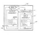
- a typical intersection cabinet (or simply “cabinet”) 102generally contains an input assembly 108 , and output assembly 112 , a controller 110 , and a malfunction management unit (MMU) 120 .
- MMUmalfunction management unit
- a malfunction management unitis a device used in traffic controller assemblies and other applications to detect and respond to conflicting or otherwise improper signals caused by a malfunctioning controller, faulty load switches, cabinet mis-wiring, improper supply voltages, or other such failure mechanisms.
- MMU unitsare typically configured as a 16-channel monitor, but may also have 32 channels, 12 channels, 6 channels, or any other number of channels.
- NEMANational Electrical Manufacturers Association
- ITSTraffic Controller Assemblies with NTCIP Requirements
- v02.06Traffic Controller Assemblies with NTCIP Requirements
- ITSAASHTO/ITE/NEMA Intelligent Transportation Systems
- TEESCaltrans Transportation Electrical Equipment Specifications
- input assembly 108typically includes an array 116 of input devices (such as vehicle detectors 117 ) which receive input signals ( 104 ) from the intersection environment through imbedded inductive loops and other such sensors.
- output assembly 112typically includes a set 114 of output devices (such as load switches 118 ) which communicate with the environment (via output 106 ) to effect traffic control via activation of the appropriate traffic signals.
- controller 110communicates with and controls the various assemblies within cabinet 102 .
- the present inventionis not limited, however, to specific controller units or communication protocols.
- MMU 120can be configured such that it receives and processes signals not only from output assembly 112 , but also controller 110 .
- MMU 120provides “field checking.” That is, MMU 120 is capable of determining the output of load switches 118 while at the same time monitoring what controller 110 has instructed those outputs to be.
- field checkis enabled for a particular channel or input, MMU 120 can check whether the actual device signals for that channel or input match the desired signal specified by controller 110 .
- an MMU 120in accordance with the present invention generally includes a display 214 , a memory 210 (e.g., RAM, ROM, EEPROM, or combination thereof), a microprocessor or microcontroller 212 , and input output (I/O) circuitry (or simply “I/O”) 208 .
- I/O 208receives signals 202 from the controller as well as signals 204 from the various load switches in the output assembly (i.e., the “field”).
- I/O 208also produces output 206 , which may be used, for example, to place the traffic intersection into emergency mode (e.g., via flashing red intersection signals) in the event of a fault.
- Display 214 of MMU 120comprises one or more display components capable of displaying information pertinent to the operation of MMU 120 as discussed below.
- display 214may include one or more displays of any type now known or developed in the future, including without limitation liquid crystal displays (LCDs), light emitting diode (LED) displays, electroluminescent displays, and the like.
- LCDsliquid crystal displays
- LEDlight emitting diode
- electroluminescent displayselectroluminescent displays
- Such displaysmight be general-purpose, pixel-based displays or custom displays with dedicated display components (“icon-based”), or a combination thereof.
- Display 214is preferably interactive (or “navigable”) in that its displayed content is responsive to some form of user input—e.g., the use of buttons, touch screen signals, or any form of direct or indirect input.
- an MMU 120in accordance with the illustrated embodiment comprises a front panel 301 having an integral display region 214 comprising an alphanumeric display 306 and two intersection status displays 308 and 309 .
- Front panel 301also includes, among other things, a button or other such actuation device 302 , and suitable I/O connectors 304 .
- the present inventionis not limited to any particular size, shape, geometry, or configuration of inputs and outputs.
- FIG. 4shows an example of suitable intersection status displays 308 and 309 .
- displays 308 and 309include a total of 16 columns, each corresponding to a different channel or approach lane associated with the intersection.
- Each columnincludes five indicators: a channel indicator 402 , a red indicator 404 , a yellow indicator 406 , a green indicator 408 , and a walk indicator 410 . It will be appreciated that only a subset of these indicators may be used, depending on how the intersection is mapped to the channels, how the MMU is configured, and whether certain standards (TS2, TS1, etc., previously referenced) are applicable.
- TS2, TS1, etc., previously referencedcertain standards
- displays 308 and 309show the status of the various intersection channels (i.e., “monitor status information”).
- channel 1might initially display a red indicator 502 while channel 2 displays a green indicator 504 ( FIG. 5A ).
- channel 2would switch to a yellow indicator 504 ( b ) ( FIG. 5B ), and eventually a red indicator 504 ( c ), at which time channel 1 would change to a green indicator 502 ( a ).
- the term “indicator” as used hereinis not limited to a dedicated display element, but encompasses pixel-based displays and the like.
- the MMUenters into a fault mode to assist the operator in diagnosing and troubleshooting the problem.
- Fault modemay be entered automatically when a fault condition has been detected.
- the diagnostic processinvolves a number of successive displays. Initially, when the system enters fault mode ( 602 ), a description of the initial fault is displayed ( 604 ). In step 606 , the help system is then activated (e.g., by the user pressing button 302 shown in FIG. 3 ). Alphanumeric display 306 then presents the appropriate help text while displays 308 and 309 present a concise set of channel status indicators (steps 608 and 610 ); that is, only a relevant subset of channel status indicators remain displayed.
- the operatormay further continue the help process (again, by pressing button 302 ) (step 612 ).
- the systemdisplays a description of the known faulty signals (step 614 ).
- the help process(step 616 ), results in a display of troubleshooting guidance (step 618 ). It will be appreciated that this process may be carried out in fewer or more steps.
- FIGS. 7A–7Ddepict one example of the successive displays occurring during a fault—specifically, a conflict-type fault. This example corresponds to a TS2 type fault with field check enabled where the channel 1 green signal is “on”, but should be “off”.
- the initial fault displayincludes a basic description of the fault (display 306 ), and a display of which signals were active at the time of fault (display 308 ).
- display 306presents a first level of help text
- display 308is modified to present a concise set of channel status indicators. That is, display 308 focuses on channels 1 and 2, and the remaining indicators are extinguished so as not to confuse the operator.
- the help processescontinues with a description of the known faulty signals (display 306 ) referencing a further simplified display 308 , which indicates that the channel 1 green signal is “on” when it should not be.
- the systemtherefore displays diagnostic information that includes a textual interpretation of the results of the field check analysis.
- display 306presents troubleshooting guidance designed to assist the operator or field technician in determining the root cause of the fault.
- FIG. 8shows a high-level fault mode decision tree applicable to the present invention.
- the decision treeprogresses from initiation of fault mode ( 802 ), to a determination of the general fault categories (boxes 816 , 818 , 820 , 830 , and 832 ).
- a computer program listingis included herewith that sets forth a particular embodiment for providing the relevant troubleshooting information.
- the systemcontinues with the context-specific help/diagnostic system.
- the initial fault displayis generated in step 804
- the fault definition text and concise signal displayare generated in step 806 after the operator presses the “help” key (or provides any suitable input) 805 .
- the help screens shown in FIG. 7correspond to a category 4 fault (steps 804 , 806 , 808 , 812 , 818 , 836 ).
- step 812If all inputs of the faulty channels have field check enabled (as determined from data 810 ), the system continues at step 812 . Otherwise, the system continues with step 814 . Under step 812 , if all inputs of the faulty channels match the control unit, processing continues with successive steps 816 and 834 , which present the operator with an “all signals match” message and troubleshooting advice. Alternatively, if any inputs of the faulty channels do not match the control unit, the known faulty signals are pinpointed ( 818 ), and further troubleshooting advice is presented to the operator ( 836 ).
- step 814corresponding to the case where not all inputs of the faulty channels have field check enabled, the system then determines whether any inputs are so enabled, then branches to steps 820 and 822 accordingly.
- step 820the system displays the potential (suspected) faulty signals as well as a setup warning regarding field check disable limitations.
- step 838the system generates further troubleshooting advice.
- step 822the system further checks whether all inputs of the faulty channels with field check enabled match. If so, processing continues with steps 830 , wherein matching signals are pinpointed.
- step 844the system then displays the remaining potential (suspected) faulty signals as well as a setup warning regarding field check disable limitations.
- step 852the system generates further troubleshooting advice.
- step 822If the result of step 822 is “No,” then the known faulty signals are pinpointed ( 832 ), the system then displays the remaining potential (suspected) faulty signals as well as a setup warning regarding field check disable limitations ( 846 ). In step 854 the system generates further troubleshooting advice.
- the MMUincorporates an advanced setup algorithm that assists the technician in accomplishing initial setup of the system at an intersection. More particularly, the setup algorithm asks a series of questions regarding the intersection geometry and operation. It then uses these responses to formulate the detailed monitor configuration parameters automatically. This eliminates the need for the technician to understand the individual monitor settings and the criteria used to determine these settings.
- the setup algorithmconverts the highly-technical signal monitor language to a system that can be easily understood by non-experts.
- these questionsinclude: “Select unused channels”; “Are pedestrian ‘Don't Walk’ signals monitored?”; “Select pedestrian channels”; and “Select protected-permissive turn channels.
- the answers received in response to these promptsare then used to configure, for example, the parameters for dual-indication monitoring, red fail monitoring, minimum yellow+red clearance monitoring, and field check monitoring. These parameters, in conjunction with other parameters and the jumpers placed on the standard program card, are used to configure the monitor.
Landscapes
- Engineering & Computer Science (AREA)
- Physics & Mathematics (AREA)
- General Physics & Mathematics (AREA)
- Human Computer Interaction (AREA)
- Automation & Control Theory (AREA)
- Tests Of Electronic Circuits (AREA)
- Testing And Monitoring For Control Systems (AREA)
- Maintenance And Management Of Digital Transmission (AREA)
Abstract
Description
Claims (14)
Priority Applications (1)
| Application Number | Priority Date | Filing Date | Title |
|---|---|---|---|
| US11/184,418US7246037B2 (en) | 2004-07-19 | 2005-07-19 | Methods and apparatus for an improved signal monitor |
Applications Claiming Priority (2)
| Application Number | Priority Date | Filing Date | Title |
|---|---|---|---|
| US58930104P | 2004-07-19 | 2004-07-19 | |
| US11/184,418US7246037B2 (en) | 2004-07-19 | 2005-07-19 | Methods and apparatus for an improved signal monitor |
Publications (2)
| Publication Number | Publication Date |
|---|---|
| US20060015295A1 US20060015295A1 (en) | 2006-01-19 |
| US7246037B2true US7246037B2 (en) | 2007-07-17 |
Family
ID=35907989
Family Applications (1)
| Application Number | Title | Priority Date | Filing Date |
|---|---|---|---|
| US11/184,418Expired - LifetimeUS7246037B2 (en) | 2004-07-19 | 2005-07-19 | Methods and apparatus for an improved signal monitor |
Country Status (3)
| Country | Link |
|---|---|
| US (1) | US7246037B2 (en) |
| CA (1) | CA2574101C (en) |
| WO (1) | WO2006020268A2 (en) |
Cited By (10)
| Publication number | Priority date | Publication date | Assignee | Title |
|---|---|---|---|---|
| US20060271359A1 (en)* | 2005-05-31 | 2006-11-30 | Microsoft Corporation | Robust decoder |
| US20060271354A1 (en)* | 2005-05-31 | 2006-11-30 | Microsoft Corporation | Audio codec post-filter |
| US20080040121A1 (en)* | 2005-05-31 | 2008-02-14 | Microsoft Corporation | Sub-band voice codec with multi-stage codebooks and redundant coding |
| US7668712B2 (en) | 2004-03-31 | 2010-02-23 | Microsoft Corporation | Audio encoding and decoding with intra frames and adaptive forward error correction |
| US9977719B1 (en) | 2013-02-01 | 2018-05-22 | Symbolic Io Corporation | Fast system state cloning |
| US10061514B2 (en) | 2015-04-15 | 2018-08-28 | Formulus Black Corporation | Method and apparatus for dense hyper IO digital retention |
| US10120607B2 (en) | 2015-04-15 | 2018-11-06 | Formulus Black Corporation | Method and apparatus for dense hyper IO digital retention |
| US10133636B2 (en) | 2013-03-12 | 2018-11-20 | Formulus Black Corporation | Data storage and retrieval mediation system and methods for using same |
| US10572186B2 (en) | 2017-12-18 | 2020-02-25 | Formulus Black Corporation | Random access memory (RAM)-based computer systems, devices, and methods |
| US10725853B2 (en) | 2019-01-02 | 2020-07-28 | Formulus Black Corporation | Systems and methods for memory failure prevention, management, and mitigation |
Families Citing this family (1)
| Publication number | Priority date | Publication date | Assignee | Title |
|---|---|---|---|---|
| US9875654B2 (en)* | 2015-01-30 | 2018-01-23 | Siemens Aktiengesellschaft | Real-time monitoring and diagnostic processing of traffic control data |
Citations (21)
| Publication number | Priority date | Publication date | Assignee | Title |
|---|---|---|---|---|
| US3729706A (en)* | 1970-10-15 | 1973-04-24 | G Hein | Portable traffic control system with television monitoring |
| US3902156A (en)* | 1974-10-07 | 1975-08-26 | Gulf & Western Industries | Multi-channel ac conflict monitor |
| US4135145A (en)* | 1976-09-07 | 1979-01-16 | Solid State Devices, Inc. | Error detecting circuit for a traffic control system |
| US4250483A (en)* | 1978-01-30 | 1981-02-10 | Rubner Anthony C | System for signalized intersection control |
| US4257029A (en)* | 1974-12-26 | 1981-03-17 | Stevens Carlile R | Traffic control system |
| US4383240A (en)* | 1981-02-24 | 1983-05-10 | Solid State Devices | Recorder of the status of a traffic control system |
| US4586041A (en)* | 1983-12-29 | 1986-04-29 | Carlson Donald A | Portable conflict monitor testing apparatus |
| US4757417A (en)* | 1984-04-19 | 1988-07-12 | The Nippon Signal Co., Ltd. | Monitoring system for load-driving switch circuits |
| US5327123A (en)* | 1992-04-23 | 1994-07-05 | Traffic Sensor Corporation | Traffic control system failure monitoring |
| US5387909A (en)* | 1993-03-25 | 1995-02-07 | Naztec, Inc. | Lamp sensing system for traffic lights |
| US5612596A (en)* | 1995-10-16 | 1997-03-18 | Conservation Load Switch, Inc. | Conservation traffic control load switch |
| US5734116A (en) | 1996-07-29 | 1998-03-31 | General Traffic Controls | Nema cabinet monitor tester |
| US20050046597A1 (en)* | 2003-08-18 | 2005-03-03 | Hutchison Michael C. | Traffic light signal system using radar-based target detection and tracking |
| US20050110660A1 (en) | 2003-11-20 | 2005-05-26 | Reno Agriculture And Electronics | Traffic control malfunction management unit with flashing don't walk monitoring |
| US20050116837A1 (en) | 2003-11-20 | 2005-06-02 | Reno Agriculture And Electronics | Traffic control malfunction management unit with selectable dual D.C. voltage monitoring |
| US20050138488A1 (en) | 2003-11-21 | 2005-06-23 | Reno Agriculture And Electronics | Traffic control malfunction management unit with per channel red enable |
| US20050138477A1 (en)* | 2003-11-25 | 2005-06-23 | Ford Motor Company | Method to facilitate failure modes and effects analysis |
| US6965322B2 (en)* | 2003-07-18 | 2005-11-15 | Eric A. Metz | Traffic signal operation during power outages |
| US20060092043A1 (en)* | 2004-11-03 | 2006-05-04 | Lagassey Paul J | Advanced automobile accident detection, data recordation and reporting system |
| US20060095199A1 (en)* | 2004-11-03 | 2006-05-04 | Lagassey Paul J | Modular intelligent transportation system |
| US20060155427A1 (en)* | 2003-02-27 | 2006-07-13 | Shaopeng Yang | Road traffic control method and traffic facilities |
- 2005
- 2005-07-19WOPCT/US2005/025490patent/WO2006020268A2/enactiveApplication Filing
- 2005-07-19USUS11/184,418patent/US7246037B2/ennot_activeExpired - Lifetime
- 2005-07-19CACA2574101Apatent/CA2574101C/ennot_activeExpired - Lifetime
Patent Citations (21)
| Publication number | Priority date | Publication date | Assignee | Title |
|---|---|---|---|---|
| US3729706A (en)* | 1970-10-15 | 1973-04-24 | G Hein | Portable traffic control system with television monitoring |
| US3902156A (en)* | 1974-10-07 | 1975-08-26 | Gulf & Western Industries | Multi-channel ac conflict monitor |
| US4257029A (en)* | 1974-12-26 | 1981-03-17 | Stevens Carlile R | Traffic control system |
| US4135145A (en)* | 1976-09-07 | 1979-01-16 | Solid State Devices, Inc. | Error detecting circuit for a traffic control system |
| US4250483A (en)* | 1978-01-30 | 1981-02-10 | Rubner Anthony C | System for signalized intersection control |
| US4383240A (en)* | 1981-02-24 | 1983-05-10 | Solid State Devices | Recorder of the status of a traffic control system |
| US4586041A (en)* | 1983-12-29 | 1986-04-29 | Carlson Donald A | Portable conflict monitor testing apparatus |
| US4757417A (en)* | 1984-04-19 | 1988-07-12 | The Nippon Signal Co., Ltd. | Monitoring system for load-driving switch circuits |
| US5327123A (en)* | 1992-04-23 | 1994-07-05 | Traffic Sensor Corporation | Traffic control system failure monitoring |
| US5387909A (en)* | 1993-03-25 | 1995-02-07 | Naztec, Inc. | Lamp sensing system for traffic lights |
| US5612596A (en)* | 1995-10-16 | 1997-03-18 | Conservation Load Switch, Inc. | Conservation traffic control load switch |
| US5734116A (en) | 1996-07-29 | 1998-03-31 | General Traffic Controls | Nema cabinet monitor tester |
| US20060155427A1 (en)* | 2003-02-27 | 2006-07-13 | Shaopeng Yang | Road traffic control method and traffic facilities |
| US6965322B2 (en)* | 2003-07-18 | 2005-11-15 | Eric A. Metz | Traffic signal operation during power outages |
| US20050046597A1 (en)* | 2003-08-18 | 2005-03-03 | Hutchison Michael C. | Traffic light signal system using radar-based target detection and tracking |
| US20050110660A1 (en) | 2003-11-20 | 2005-05-26 | Reno Agriculture And Electronics | Traffic control malfunction management unit with flashing don't walk monitoring |
| US20050116837A1 (en) | 2003-11-20 | 2005-06-02 | Reno Agriculture And Electronics | Traffic control malfunction management unit with selectable dual D.C. voltage monitoring |
| US20050138488A1 (en) | 2003-11-21 | 2005-06-23 | Reno Agriculture And Electronics | Traffic control malfunction management unit with per channel red enable |
| US20050138477A1 (en)* | 2003-11-25 | 2005-06-23 | Ford Motor Company | Method to facilitate failure modes and effects analysis |
| US20060092043A1 (en)* | 2004-11-03 | 2006-05-04 | Lagassey Paul J | Advanced automobile accident detection, data recordation and reporting system |
| US20060095199A1 (en)* | 2004-11-03 | 2006-05-04 | Lagassey Paul J | Modular intelligent transportation system |
Non-Patent Citations (7)
| Title |
|---|
| Information Sheet by Eberle Design Inc., entitled "MMU-16E Malfunction Management Unit, Introducing A New Standard of Safety and Diagnostic Capabilities", dated Oct. 19, 2001 (p. 1). |
| Information Sheet by Eberle Design Inc., entitled "SSM-LE Series, Enhanced NEMA Signal Monitor Unit", dated Sep. 2001 (p. 1). |
| International Search Report for PCT/US2005/25490, mailed Aug. 11, 2006. |
| Operating Manual by Peek Traffic Systems, Inc., entitled Double Diamond MMU Operating Manual, Production Release Version 1, dated Aug. 7, 2000 (pp. 1-74). |
| Operations Manual by Eberle Design Inc., entitled "MMU-16E Series, RMS Signal Monitor", Revision dated Jan. 2001 (pp. 1-24). |
| Operations Manual by Eberle Design Inc., entitled "SSM-LE Series, RMS Signal Monitor", Revision dated Dec. 2000 (pp. 1-20). |
| Webpage Information Sheet at www.peek-trafic.com/products/cabinets/doublediamond.html, by Quixote Traffic Corporation, entitled "Double Diamond NEMA MMU and Conflict Monitor", webpage printed Sep. 7, 2005 (pp. 1-2). |
Cited By (23)
| Publication number | Priority date | Publication date | Assignee | Title |
|---|---|---|---|---|
| US7668712B2 (en) | 2004-03-31 | 2010-02-23 | Microsoft Corporation | Audio encoding and decoding with intra frames and adaptive forward error correction |
| US20100125455A1 (en)* | 2004-03-31 | 2010-05-20 | Microsoft Corporation | Audio encoding and decoding with intra frames and adaptive forward error correction |
| US7734465B2 (en) | 2005-05-31 | 2010-06-08 | Microsoft Corporation | Sub-band voice codec with multi-stage codebooks and redundant coding |
| US7962335B2 (en) | 2005-05-31 | 2011-06-14 | Microsoft Corporation | Robust decoder |
| US20080040105A1 (en)* | 2005-05-31 | 2008-02-14 | Microsoft Corporation | Sub-band voice codec with multi-stage codebooks and redundant coding |
| US7590531B2 (en) | 2005-05-31 | 2009-09-15 | Microsoft Corporation | Robust decoder |
| US20090276212A1 (en)* | 2005-05-31 | 2009-11-05 | Microsoft Corporation | Robust decoder |
| US20060271354A1 (en)* | 2005-05-31 | 2006-11-30 | Microsoft Corporation | Audio codec post-filter |
| US7707034B2 (en) | 2005-05-31 | 2010-04-27 | Microsoft Corporation | Audio codec post-filter |
| US20060271373A1 (en)* | 2005-05-31 | 2006-11-30 | Microsoft Corporation | Robust decoder |
| US20060271359A1 (en)* | 2005-05-31 | 2006-11-30 | Microsoft Corporation | Robust decoder |
| US7831421B2 (en)* | 2005-05-31 | 2010-11-09 | Microsoft Corporation | Robust decoder |
| US7904293B2 (en) | 2005-05-31 | 2011-03-08 | Microsoft Corporation | Sub-band voice codec with multi-stage codebooks and redundant coding |
| US20080040121A1 (en)* | 2005-05-31 | 2008-02-14 | Microsoft Corporation | Sub-band voice codec with multi-stage codebooks and redundant coding |
| US9977719B1 (en) | 2013-02-01 | 2018-05-22 | Symbolic Io Corporation | Fast system state cloning |
| US10789137B2 (en) | 2013-02-01 | 2020-09-29 | Formulus Black Corporation | Fast system state cloning |
| US10133636B2 (en) | 2013-03-12 | 2018-11-20 | Formulus Black Corporation | Data storage and retrieval mediation system and methods for using same |
| US10061514B2 (en) | 2015-04-15 | 2018-08-28 | Formulus Black Corporation | Method and apparatus for dense hyper IO digital retention |
| US10120607B2 (en) | 2015-04-15 | 2018-11-06 | Formulus Black Corporation | Method and apparatus for dense hyper IO digital retention |
| US10346047B2 (en) | 2015-04-15 | 2019-07-09 | Formulus Black Corporation | Method and apparatus for dense hyper IO digital retention |
| US10606482B2 (en) | 2015-04-15 | 2020-03-31 | Formulus Black Corporation | Method and apparatus for dense hyper IO digital retention |
| US10572186B2 (en) | 2017-12-18 | 2020-02-25 | Formulus Black Corporation | Random access memory (RAM)-based computer systems, devices, and methods |
| US10725853B2 (en) | 2019-01-02 | 2020-07-28 | Formulus Black Corporation | Systems and methods for memory failure prevention, management, and mitigation |
Also Published As
| Publication number | Publication date |
|---|---|
| WO2006020268A3 (en) | 2006-10-05 |
| WO2006020268A2 (en) | 2006-02-23 |
| CA2574101A1 (en) | 2006-02-23 |
| US20060015295A1 (en) | 2006-01-19 |
| CA2574101C (en) | 2013-06-25 |
Similar Documents
| Publication | Publication Date | Title |
|---|---|---|
| US7246037B2 (en) | Methods and apparatus for an improved signal monitor | |
| CN103425119B (en) | Test system, equipment management device and vehicle performance test system | |
| US9123218B2 (en) | Fire control panel with a display unit for displaying system information | |
| KR101418479B1 (en) | Fly-by-wire flight control system having an integrated ofp function using a flight type identity signal and method for controlling the same | |
| KR101621434B1 (en) | Operating error detecting system of human operator process in virtual training system and human operator training process for nuclear power plant | |
| US6028441A (en) | Self-test routine and circuit for LED display | |
| EP4300456A1 (en) | Fire detection system testing | |
| EP2154591A1 (en) | Device and method for testing systems with visual output | |
| JPH10319180A (en) | Plant failure recovery support system | |
| CN106149281A (en) | Washing machine and trouble shooting method thereof | |
| KR101102603B1 (en) | Inspection device of relay element driving circuit | |
| US7378987B2 (en) | Traffic control malfunction management unit with per channel red enable | |
| CN117504215A (en) | Portable online fire-extinguishing explosion-suppression detection system, device and detection method thereof | |
| US6087964A (en) | Vehicle detector with operational display | |
| US20050110660A1 (en) | Traffic control malfunction management unit with flashing don't walk monitoring | |
| AU2012259494A1 (en) | Method and device for fault search of a vehicle | |
| CN114815771A (en) | Vehicle fault diagnosis method and device and vehicle | |
| CN115032328A (en) | False alarm prevention control system and control method for gas leakage detection in vehicle | |
| US7109886B2 (en) | Traffic control malfunction management unit with co-channel monitoring | |
| KR102283187B1 (en) | Method for monitoring equipment in combat system | |
| KR20010076717A (en) | Advanced Alarm System of Main Control Room in Nuclear Power Plant | |
| JPH10160894A (en) | Man-machine interface device | |
| KR102572263B1 (en) | Residual indicator control system with error detection and handling functions | |
| JP4600081B2 (en) | Operation support system and operation support method | |
| CN115240836A (en) | Method, device, system, equipment and program product for controlling running state |
Legal Events
| Date | Code | Title | Description |
|---|---|---|---|
| AS | Assignment | Owner name:EBERLE DESIGN, INC., ARIZONA Free format text:ASSIGNMENT OF ASSIGNORS INTEREST;ASSIGNOR:EVANS, SCOTT R.;REEL/FRAME:016798/0053 Effective date:20050719 | |
| STCF | Information on status: patent grant | Free format text:PATENTED CASE | |
| AS | Assignment | Owner name:U.S. BANK NATIONAL ASSOCIATION, MINNESOTA Free format text:SECURITY AGREEMENT;ASSIGNOR:EBERLE DESIGN, INC.;REEL/FRAME:025498/0332 Effective date:20101215 | |
| FPAY | Fee payment | Year of fee payment:4 | |
| AS | Assignment | Owner name:ARES CAPITAL CORPORATION, DISTRICT OF COLUMBIA Free format text:SECURITY AGREEMENT;ASSIGNOR:EBERLE DESIGN, INC.;REEL/FRAME:031086/0709 Effective date:20130826 | |
| AS | Assignment | Owner name:EBERLE DESIGN, INC., ARIZONA Free format text:TERMINATION AND RELEASE OF PATENT SECURITY AGREEMENT RECORDED AT REEL 025498/FRAME 0332;ASSIGNOR:U.S. BANK NATIONAL ASSOCIATION;REEL/FRAME:031096/0229 Effective date:20130826 | |
| AS | Assignment | Owner name:EBERLE DESIGN, INC., ARIZONA Free format text:RELEASE BY SECURED PARTY;ASSIGNOR:ARES CAPITAL CORPORATION, AS ADMINISTRATIVE AGENT;REEL/FRAME:032574/0480 Effective date:20140331 Owner name:RENO A&E, LLC, NEVADA Free format text:RELEASE BY SECURED PARTY;ASSIGNOR:ARES CAPITAL CORPORATION, AS ADMINISTRATIVE AGENT;REEL/FRAME:032574/0480 Effective date:20140331 | |
| AS | Assignment | Owner name:CREDIT SUISSE AG, CAYMAN ISLANDS BRANCH, AS COLLAT Free format text:PATENT SECURITY AGREEMENT (SECOND LIEN);ASSIGNORS:FLINT TRADING, INC.;ENNIS PAINT, INC.;EBERLE DESIGN, INC.;AND OTHERS;REEL/FRAME:032591/0239 Effective date:20140331 Owner name:CREDIT SUISSE AG, CAYMAN ISLANDS BRANCH, AS COLLAT Free format text:PATENT SECURITY AGREEMENT (FIRST LIEN);ASSIGNORS:FLINT TRADING, INC.;ENNIS PAINT, INC.;EBERLE DESIGN, INC.;AND OTHERS;REEL/FRAME:032591/0275 Effective date:20140331 | |
| FPAY | Fee payment | Year of fee payment:8 | |
| AS | Assignment | Owner name:ANTARES CAPITAL LP, ILLINOIS Free format text:SECURITY INTEREST;ASSIGNORS:ENNIS PAINT, INC.;FLINT TRADING, INC.;EBERLE DESIGN, INC.;AND OTHERS;REEL/FRAME:038978/0976 Effective date:20160613 | |
| AS | Assignment | Owner name:FLINT TRADING, INC., NORTH CAROLINA Free format text:TERMINATION OF SECURITY INTEREST IN PATENTS;ASSIGNOR:CREDIT SUISSE AG, CAYMAN ISLANDS BRANCH;REEL/FRAME:039025/0196 Effective date:20160613 Owner name:RENO A&E, LLC, NEVADA Free format text:TERMINATION OF SECURITY INTEREST IN PATENTS;ASSIGNOR:CREDIT SUISSE AG, CAYMAN ISLANDS BRANCH;REEL/FRAME:039025/0196 Effective date:20160613 Owner name:ENNIS PAINT, INC., NORTH CAROLINA Free format text:TERMINATION OF SECURITY INTEREST IN PATENTS;ASSIGNOR:CREDIT SUISSE AG, CAYMAN ISLANDS BRANCH;REEL/FRAME:039025/0196 Effective date:20160613 Owner name:EBERLE DESIGN, INC., ARIZONA Free format text:TERMINATION OF SECURITY INTEREST IN PATENTS;ASSIGNOR:CREDIT SUISSE AG, CAYMAN ISLANDS BRANCH;REEL/FRAME:039025/0196 Effective date:20160613 Owner name:RENO A&E, LLC, NEVADA Free format text:TERMINATION OF SECURITY INTEREST IN PATENTS;ASSIGNOR:CREDIT SUISSE AG, CAYMAN ISLANDS BRANCH;REEL/FRAME:039025/0246 Effective date:20160613 Owner name:FLINT TRADING, INC., NORTH CAROLINA Free format text:TERMINATION OF SECURITY INTEREST IN PATENTS;ASSIGNOR:CREDIT SUISSE AG, CAYMAN ISLANDS BRANCH;REEL/FRAME:039025/0246 Effective date:20160613 Owner name:EBERLE DESIGN, INC., ARIZONA Free format text:TERMINATION OF SECURITY INTEREST IN PATENTS;ASSIGNOR:CREDIT SUISSE AG, CAYMAN ISLANDS BRANCH;REEL/FRAME:039025/0246 Effective date:20160613 Owner name:ENNIS PAINT, INC., NORTH CAROLINA Free format text:TERMINATION OF SECURITY INTEREST IN PATENTS;ASSIGNOR:CREDIT SUISSE AG, CAYMAN ISLANDS BRANCH;REEL/FRAME:039025/0246 Effective date:20160613 | |
| AS | Assignment | Owner name:WILMINGTON TRUST, NATIONAL ASSOCIATION, AS ADMINISTRATIVE AGENT, DELAWARE Free format text:SECURITY INTEREST;ASSIGNORS:ENNIS PAINT, INC.;FLINT TRADING, INC.;EBERLE DESIGN, INC.;AND OTHERS;REEL/FRAME:039128/0732 Effective date:20160613 Owner name:WILMINGTON TRUST, NATIONAL ASSOCIATION, AS ADMINIS Free format text:SECURITY INTEREST;ASSIGNORS:ENNIS PAINT, INC.;FLINT TRADING, INC.;EBERLE DESIGN, INC.;AND OTHERS;REEL/FRAME:039128/0732 Effective date:20160613 | |
| MAFP | Maintenance fee payment | Free format text:PAYMENT OF MAINTENANCE FEE, 12TH YR, SMALL ENTITY (ORIGINAL EVENT CODE: M2553); ENTITY STATUS OF PATENT OWNER: SMALL ENTITY Year of fee payment:12 | |
| AS | Assignment | Owner name:EBERLE DESIGN, INC., ARIZONA Free format text:RELEASE BY SECURED PARTY;ASSIGNOR:ANTARES CAPITAL LP, AS ADMINISTRATIVE AGENT;REEL/FRAME:054864/0024 Effective date:20201223 Owner name:ENNIS PAINT, INC., NORTH CAROLINA Free format text:RELEASE BY SECURED PARTY;ASSIGNOR:ANTARES CAPITAL LP, AS ADMINISTRATIVE AGENT;REEL/FRAME:054864/0024 Effective date:20201223 Owner name:FLINT TRADING, INC., NORTH CAROLINA Free format text:RELEASE BY SECURED PARTY;ASSIGNOR:ANTARES CAPITAL LP, AS ADMINISTRATIVE AGENT;REEL/FRAME:054864/0024 Effective date:20201223 Owner name:RENO A&E, LLC, NEVADA Free format text:RELEASE BY SECURED PARTY;ASSIGNOR:ANTARES CAPITAL LP, AS ADMINISTRATIVE AGENT;REEL/FRAME:054864/0024 Effective date:20201223 | |
| AS | Assignment | Owner name:FLINT TRADING INC., NORTH CAROLINA Free format text:RELEASE BY SECURED PARTY;ASSIGNOR:WILMINGTON TRUST, NATIONAL ASSOCIATION;REEL/FRAME:054896/0344 Effective date:20201223 Owner name:RENO A&E LLC, NORTH CAROLINA Free format text:RELEASE BY SECURED PARTY;ASSIGNOR:WILMINGTON TRUST, NATIONAL ASSOCIATION;REEL/FRAME:054896/0344 Effective date:20201223 Owner name:EBERLE DESIGN INC., NORTH CAROLINA Free format text:RELEASE BY SECURED PARTY;ASSIGNOR:WILMINGTON TRUST, NATIONAL ASSOCIATION;REEL/FRAME:054896/0344 Effective date:20201223 Owner name:ENNIS PAINT INC., NORTH CAROLINA Free format text:RELEASE BY SECURED PARTY;ASSIGNOR:WILMINGTON TRUST, NATIONAL ASSOCIATION;REEL/FRAME:054896/0344 Effective date:20201223 | |
| AS | Assignment | Owner name:BARINGS FINANCE LLC, AS ADMINISTRATIVE AGENT, NORTH CAROLINA Free format text:SECURITY INTEREST;ASSIGNOR:EBERLE DESIGN LLC;REEL/FRAME:060207/0307 Effective date:20220614 |