US7245279B2 - Linear led array - Google Patents
Linear led arrayDownload PDFInfo
- Publication number
- US7245279B2 US7245279B2US10/728,152US72815203AUS7245279B2US 7245279 B2US7245279 B2US 7245279B2US 72815203 AUS72815203 AUS 72815203AUS 7245279 B2US7245279 B2US 7245279B2
- Authority
- US
- United States
- Prior art keywords
- led
- pcb
- waterproof
- tray housing
- housing
- Prior art date
- Legal status (The legal status is an assumption and is not a legal conclusion. Google has not performed a legal analysis and makes no representation as to the accuracy of the status listed.)
- Expired - Fee Related, expires
Links
- 239000011347resinSubstances0.000claimsabstractdescription9
- 229920005989resinPolymers0.000claimsabstractdescription9
- 239000000463materialSubstances0.000claimsdescription4
- 238000007789sealingMethods0.000claimsdescription4
- 239000003822epoxy resinSubstances0.000claimsdescription2
- 229920000647polyepoxidePolymers0.000claimsdescription2
- 150000003071polychlorinated biphenylsChemical class0.000claims4
- 238000005476solderingMethods0.000claims2
- 239000004850liquid epoxy resins (LERs)Substances0.000claims1
- 239000000499gelSubstances0.000description6
- ZKGSEEWIVLAUNH-UHFFFAOYSA-N1,2,3-trichloro-4-(3-chlorophenyl)benzeneChemical compoundClC1=CC=CC(C=2C(=C(Cl)C(Cl)=CC=2)Cl)=C1ZKGSEEWIVLAUNH-UHFFFAOYSA-N0.000description5
- 239000004033plasticSubstances0.000description4
- 238000010438heat treatmentMethods0.000description3
- 239000007788liquidSubstances0.000description3
- 239000004593EpoxySubstances0.000description2
- 238000010586diagramMethods0.000description2
- XLYOFNOQVPJJNP-UHFFFAOYSA-NwaterSubstancesOXLYOFNOQVPJJNP-UHFFFAOYSA-N0.000description2
- 241000191291Abies albaSpecies0.000description1
- VYPSYNLAJGMNEJ-UHFFFAOYSA-NSilicium dioxideChemical compoundO=[Si]=OVYPSYNLAJGMNEJ-UHFFFAOYSA-N0.000description1
- 239000003086colorantSubstances0.000description1
- 238000005034decorationMethods0.000description1
- 238000000034methodMethods0.000description1
- 229910052754neonInorganic materials0.000description1
- GKAOGPIIYCISHV-UHFFFAOYSA-Nneon atomChemical compound[Ne]GKAOGPIIYCISHV-UHFFFAOYSA-N0.000description1
- 230000007935neutral effectEffects0.000description1
- 239000004417polycarbonateSubstances0.000description1
- 229920000515polycarbonatePolymers0.000description1
- 239000000741silica gelSubstances0.000description1
- 229910002027silica gelInorganic materials0.000description1
- 239000007787solidSubstances0.000description1
Images


Classifications
- G—PHYSICS
- G09—EDUCATION; CRYPTOGRAPHY; DISPLAY; ADVERTISING; SEALS
- G09F—DISPLAYING; ADVERTISING; SIGNS; LABELS OR NAME-PLATES; SEALS
- G09F9/00—Indicating arrangements for variable information in which the information is built-up on a support by selection or combination of individual elements
- G09F9/30—Indicating arrangements for variable information in which the information is built-up on a support by selection or combination of individual elements in which the desired character or characters are formed by combining individual elements
- G09F9/33—Indicating arrangements for variable information in which the information is built-up on a support by selection or combination of individual elements in which the desired character or characters are formed by combining individual elements being semiconductor devices, e.g. diodes
- H—ELECTRICITY
- H05—ELECTRIC TECHNIQUES NOT OTHERWISE PROVIDED FOR
- H05K—PRINTED CIRCUITS; CASINGS OR CONSTRUCTIONAL DETAILS OF ELECTRIC APPARATUS; MANUFACTURE OF ASSEMBLAGES OF ELECTRICAL COMPONENTS
- H05K3/00—Apparatus or processes for manufacturing printed circuits
- H05K3/22—Secondary treatment of printed circuits
- H05K3/28—Applying non-metallic protective coatings
- H05K3/284—Applying non-metallic protective coatings for encapsulating mounted components
Definitions
- the present inventionrelates to a light emitting diode (LED) display array, and more particularly to a waterproof LED display array that has a watertight housing.
- LEDlight emitting diode
- LED displaysare often used in signboard advertising.
- LED displaysnormally comprise a rectangular or hex array of LEDs mounted on one or more printed circuit boards (PCB) controlled by special hardware and/or software to perform certain images on a screen to provide images to attract the attention of potential customers.
- PCBprinted circuit boards
- Such LED displaysare also widely used by families or individuals for other purposes, such as Christmas tree decorations.
- LED displaysmust be placed outdoors.
- an LED display with waterproof functionbecomes desirable.
- Traditional covered LED displayssuch as U.S. Pat. No. 6,501,084 by Sakai et al, show a housing with a cover and several LEDs mounted on a PCB inside the housing.
- the waterproof coverwas not sealed properly, water or water vapor can easily penetrate the LED display so that the LED display will fail quickly.
- the main objective of the present inventionis to provide an LED display array that is entirely waterproof.
- the second objective of the present inventionis to provide an LED array which is easily extendable, from at least one set of the LED display unit to as many as the users prefer for any particular needs in comparatively low cost.
- the third objective of the present inventionis to provide an LED array that is easy to be set up.
- the present inventionprovides an easily extendable design of waterproof LED display array.
- the LED display unitis made to function separately, and each LED display unit has its own waterproof arrangement, as it lowers the cost extending the length of the array.
- Such designcan be used as substitute of neon lights, while simply allowing the user to wire such LED display array around already existed structure, such as non-glimmering advertisement. It provides flexibility and great economic savings for the users.
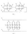
- FIG. 1is a theoretical circuit diagram showing of the present invention.
- FIG. 2is a physical linkage circuit diagram showing external power supply.
- FIG. 3is a perspective view.
- FIG. 4is a side cross section view.
- FIG. 1illustrates a theoretical circuit equivalent of the first embodiment of the LED extensible array.
- the external power source portionsare abstract, emphasizing the linkage of the units.
- FIG. 2illustrates the second embodiment of the present invention, showing the parallel link of the external power supplies.
- the LED display unit 10consists four light emitting diode (LED) elements 31 separately connected as two pairs. Two pairs of LED elements 31 are connected in parallel to the external power source. The power source supplies power to the LED elements 31 via the resistors 30 . The resistors 30 are connected to an anode of each pair of LED elements 31 .
- LEDlight emitting diode
- the character of the resistor 30 scan be applied according to a user's demand.
- the resistor 30 value of 27 ⁇ /0.25 wis favored.
- the LED elements 31can also be selected from variety of different volumes. In present invention, red, blue, green, amber, and white LED elements 31 are described, but other colors can also be used.
- the DC power supplyis preferably to be set at 12V.
- a standard power supply with the capability producing an output of 12V from commonly used AC 100-120V/0.8 Ais preferred.
- the powercan also be up to 36V DC, but preferably above 2V DC.
- the external power supplyconnects to each LED display unit 10 individually and separately.
- the external power supplyconsists a positive power source 20 and a negative power source 21 .
- the positive voltage power source 20connects to the anode ends of each LED elements 31 through resistor 30 s
- the negative voltage power source 21connects to the cathode ends of each LED elements 31 .
- Two LED elements 31are connected serially with one resistor 30 connected to the anode end, constituting an LED group.
- Two LED groupsconnect in parallel to the external power source, constituting one LED display unit 10 .
- the number of LED display unit 10is extendable by simply adding extra LED display units 10 in chain.
- the procedurecan be done by connecting the positive voltage supply to the anode ends of each LED group and connecting the negative voltage supply to the cathode ends of each LED groups.
- Each individual LED or a pair of LEDsis preferably constructed in a parallel configuration within the unit 10 .
- the parallel configurationassures that the failure of a single LED or a failure of a pair of LEDs does not lead to failure of all LEDs within the unit 10 .
- Other analogous circuitscan be used for LED lamps having different voltages and current limitations.
- the physical embodiment of the inventionappears as a chain of tray links.
- the intermediate wire connectionsare flexible allowing flexibility of the entire chain of tray links.
- Each traycorresponds with a unit 10 .
- Each link formed as a rectangular trayis preferably white in color and made of plastic.
- the white plastic traysare linked together by strands of wire that are preferably color neutral such as gray and white, or gray and black.
- the chain of trayscan receive hook and loop tape on the underside of each tray so that the chain can be attached to a display sign.
- Common display signsinclude lettering such that the chain can be inserted inside and mounted inside the display sign.
- the chainhas positive and negative electrical leads that power the chain.
- the electrical leadsprotrude from both ends of the chain.
- the pair of positive and negative leads as a first endcan be powered, or the pair of positive and negative leads at the second end can be powered.
- a usercan interchange the end from which the device is powered.
- the parallel circuitallows a user to cut off links of the chain to a desired length.
- a usercan use a pair of scissors to cut the wire strands holding the links together.
- the external power supplyis connected to the positive and negative electrical leads at either end.
- a wide variety of external power suppliescan be used. These external power supplies are well-known in the art and not a discussion subject of this application.
- Each link 10is a plastic tray, which can be made of PVC or polycarbonate material.
- the trayseach hold a plurality of LED's in linear configuration pointing upward.
- the plastic traysare linked together by one or more strands of wire pairs with positive and negative leads.
- Each individual LED display unithas a housing 62 on which a top opening is formed.
- the housinghas an elongate and rectangular box shape. The opening is formed on the upper end of the housing so that the housing resembles a tray 62 .
- the PCB 55has an elongate rectangular plate shape corresponding to and fitting inside the housing 62 .
- required number of LED elements 31is soldered on a PCB 55 , along with required number of resistors 30 .
- Preferably four LED elements and two resistorsare accommodated on one PCB 55 .
- Plural or four LED elements 31are mounted on an upper side of the PCB 55 so that its light emitting side is faced to the opening of the housing.
- the LED elements 31are disposed at predetermined intervals in the longitudinal direction.
- An external power sourcesupplies power to the LED elements and other electrical elements via the leads.
- the leadsare secured to the front and rear ends of the housing.
- the PCBcan be coated with reflective material to direct light outwards.
- the PCBcan also be covered with a reflector mirror surface either integrally formed or laying on top of the PCB so that LED light is directed upward.
- the resincovers the reflective surface in both cases.
- An outer cover 45is attached to the opening of the housing.
- the gelspreads over the PCB and preferably through the PCB via holes in the PCB board allowing flow.
- the liquid gelflows around the edges of the PCB providing a watertight seal for all elements on the PCB.
- the level of the liquidis defined as the surface 45 of the outer cover.
- the coverhas an elongate rectangular shape corresponding to the inner edge of the opening.
- the outer coveris a waterproof resin that has certain predetermined openings allowing the light-emitting portion of the LED elements to protrude into the ambient atmosphere.
- the housing under the outer coveris closely attached to the housing, sealing the PCB and other electrical elements inside the housing.
- the unit 10is made by preparing a layer of waterproof epoxy gel spread on and over the covered housing with the PCB and the LED elements inside the housing.
- the gelis also spread on and over the light emitting portion of the LED elements and the necessary power supply wires.
- an electrical heat shrink covercan envelop the lower portion of the LED before the lower portion of the LED is encased within the epoxy gel.
- the electrical heat shrink cover formed as a tube fitted over the LED,provides a watertight seal with the LED becoming integrally formed with the LED such that it becomes the bottom portion of the LED.
- the waterproof gelis preferably formed from epoxy resin but can be made of a variety of other materials.
- the PCB and related elementsis encased inside the housing.
- the liquidis cured to a solid state upon heating.
- a certain heating time upon the LED unitmay be required to cure to waterproof standards. In the preferred embodiment, eight hours heating time in oven is favored.
Landscapes
- Physics & Mathematics (AREA)
- General Physics & Mathematics (AREA)
- Engineering & Computer Science (AREA)
- Theoretical Computer Science (AREA)
- Illuminated Signs And Luminous Advertising (AREA)
Abstract
Description
Claims (14)
Priority Applications (1)
| Application Number | Priority Date | Filing Date | Title |
|---|---|---|---|
| US10/728,152US7245279B2 (en) | 2003-12-04 | 2003-12-04 | Linear led array |
Applications Claiming Priority (1)
| Application Number | Priority Date | Filing Date | Title |
|---|---|---|---|
| US10/728,152US7245279B2 (en) | 2003-12-04 | 2003-12-04 | Linear led array |
Publications (2)
| Publication Number | Publication Date |
|---|---|
| US20050122293A1 US20050122293A1 (en) | 2005-06-09 |
| US7245279B2true US7245279B2 (en) | 2007-07-17 |
Family
ID=34633634
Family Applications (1)
| Application Number | Title | Priority Date | Filing Date |
|---|---|---|---|
| US10/728,152Expired - Fee RelatedUS7245279B2 (en) | 2003-12-04 | 2003-12-04 | Linear led array |
Country Status (1)
| Country | Link |
|---|---|
| US (1) | US7245279B2 (en) |
Cited By (18)
| Publication number | Priority date | Publication date | Assignee | Title |
|---|---|---|---|---|
| US20080086922A1 (en)* | 2006-09-07 | 2008-04-17 | Shanghai Sansi Electronic Engineering Co., Ltd. | Luminous sign with encapsulated led chips |
| US20080310156A1 (en)* | 2006-10-17 | 2008-12-18 | Baoliang Wang | Led illuminating device |
| US20100117560A1 (en)* | 2006-10-03 | 2010-05-13 | Cao Group, Inc. | Pixilated LED Light Source for Channel Letter Illumination |
| US20100254116A1 (en)* | 2007-10-30 | 2010-10-07 | Lg Electronics Inc. | Lighting apparatus and refrigerator having the same |
| US20100302789A1 (en)* | 2009-05-28 | 2010-12-02 | Qing Li | LED Light Source Module and Method for Producing the Same |
| US20110148746A1 (en)* | 2009-12-18 | 2011-06-23 | Philip Eric Devorris | Sealed flexible light emitting diode display system with remote waterproof control |
| US20110194284A1 (en)* | 2008-12-12 | 2011-08-11 | The Sloan Company, Inc. Dba Sloanled | Channel letter lighting system using high output white light emitting diodes |
| US20110209368A1 (en)* | 2008-12-12 | 2011-09-01 | The Sloan Company, Inc. Dba Sloanled | Angled emitter channel letter lighting |
| US20120236547A1 (en)* | 2011-02-25 | 2012-09-20 | Hartman Michael S | Lighting assembly and illuminated decking |
| US20120275153A1 (en)* | 2011-04-29 | 2012-11-01 | Zimmerman Joseph J | Flat panel light |
| US9170000B2 (en) | 2008-12-12 | 2015-10-27 | The Sloan Company, Inc. | Angled emitter channel letter lighting |
| US9303861B2 (en) | 2009-09-14 | 2016-04-05 | Us Vaopto, Inc. | Light emitting diode light source modules |
| US9916782B2 (en) | 2013-12-31 | 2018-03-13 | Ultravision Technologies, Llc | Modular display panel |
| US10061553B2 (en) | 2013-12-31 | 2018-08-28 | Ultravision Technologies, Llc | Power and data communication arrangement between panels |
| US10248372B2 (en) | 2013-12-31 | 2019-04-02 | Ultravision Technologies, Llc | Modular display panels |
| US10706770B2 (en) | 2014-07-16 | 2020-07-07 | Ultravision Technologies, Llc | Display system having module display panel with circuitry for bidirectional communication |
| US10891881B2 (en) | 2012-07-30 | 2021-01-12 | Ultravision Technologies, Llc | Lighting assembly with LEDs and optical elements |
| US20210126445A1 (en)* | 2019-10-23 | 2021-04-29 | Cable Management Solutions Inc. | Cable conveyance systems incorporating electronic visual displays |
Families Citing this family (16)
| Publication number | Priority date | Publication date | Assignee | Title |
|---|---|---|---|---|
| US20040052076A1 (en)* | 1997-08-26 | 2004-03-18 | Mueller George G. | Controlled lighting methods and apparatus |
| US7352339B2 (en)* | 1997-08-26 | 2008-04-01 | Philips Solid-State Lighting Solutions | Diffuse illumination systems and methods |
| US6720745B2 (en)* | 1997-08-26 | 2004-04-13 | Color Kinetics, Incorporated | Data delivery track |
| US7161313B2 (en)* | 1997-08-26 | 2007-01-09 | Color Kinetics Incorporated | Light emitting diode based products |
| US20020176259A1 (en) | 1999-11-18 | 2002-11-28 | Ducharme Alfred D. | Systems and methods for converting illumination |
| US7202613B2 (en) | 2001-05-30 | 2007-04-10 | Color Kinetics Incorporated | Controlled lighting methods and apparatus |
| US7300192B2 (en) | 2002-10-03 | 2007-11-27 | Color Kinetics Incorporated | Methods and apparatus for illuminating environments |
| DE202006005045U1 (en)* | 2006-03-24 | 2007-08-09 | Würth Elektronik Rot am See GmbH & Co. KG | Printed circuit board module, has connecting device provided at printed circuit board for direct mechanical or electrical connection with another printed circuit board module comprising similar connecting device |
| US9564070B2 (en)* | 2006-10-05 | 2017-02-07 | GE Lighting Solutions, LLC | LED backlighting system for cabinet sign |
| EP2070071B1 (en)* | 2006-10-05 | 2016-11-16 | GE Lighting Solutions, LLC | Led backlighting system for cabinet sign |
| US20080089064A1 (en)* | 2006-10-17 | 2008-04-17 | Baoliang Wang | LED Illuminating device |
| US7697925B1 (en)* | 2007-01-23 | 2010-04-13 | Sprint Communications Company L.P. | Synchronized light shows on cellular handsets of users at a gathering |
| KR101641860B1 (en)* | 2010-05-12 | 2016-07-29 | 엘지이노텍 주식회사 | Light-emitting element array, Backlight apparatus, and Illumination apparatus |
| SG10201408159TA (en)* | 2014-12-06 | 2016-07-28 | Vertical Software Asia Pte Ltd | Authentication method |
| CN206347374U (en)* | 2016-11-11 | 2017-07-21 | 江苏飞天照明有限公司 | LED meteor shower rainbow tubes |
| CN108954026B (en)* | 2018-08-29 | 2024-04-16 | 深圳市信合光电照明有限公司 | Split type 2-wire external control full-color LED lamp |
Citations (5)
| Publication number | Priority date | Publication date | Assignee | Title |
|---|---|---|---|---|
| US6329593B1 (en)* | 2000-05-01 | 2001-12-11 | Formosa Industrial Computing Inc. | Waterproof led display |
| US6364507B1 (en)* | 2000-05-01 | 2002-04-02 | Formosa Industrial Computing Inc. | Waterproof LED display |
| US6448900B1 (en)* | 1999-10-14 | 2002-09-10 | Jong Chen | Easy-to-assembly LED display for any graphics and text |
| US6501084B1 (en)* | 1999-03-31 | 2002-12-31 | Toyoda Gosei Co., Ltd. | Lamp unit using short-wave light emitting device |
| US20030189829A1 (en)* | 2001-08-09 | 2003-10-09 | Matsushita Electric Industrial Co., Ltd. | LED illumination apparatus and card-type LED illumination source |
- 2003
- 2003-12-04USUS10/728,152patent/US7245279B2/ennot_activeExpired - Fee Related
Patent Citations (5)
| Publication number | Priority date | Publication date | Assignee | Title |
|---|---|---|---|---|
| US6501084B1 (en)* | 1999-03-31 | 2002-12-31 | Toyoda Gosei Co., Ltd. | Lamp unit using short-wave light emitting device |
| US6448900B1 (en)* | 1999-10-14 | 2002-09-10 | Jong Chen | Easy-to-assembly LED display for any graphics and text |
| US6329593B1 (en)* | 2000-05-01 | 2001-12-11 | Formosa Industrial Computing Inc. | Waterproof led display |
| US6364507B1 (en)* | 2000-05-01 | 2002-04-02 | Formosa Industrial Computing Inc. | Waterproof LED display |
| US20030189829A1 (en)* | 2001-08-09 | 2003-10-09 | Matsushita Electric Industrial Co., Ltd. | LED illumination apparatus and card-type LED illumination source |
Cited By (33)
| Publication number | Priority date | Publication date | Assignee | Title |
|---|---|---|---|---|
| US20080086922A1 (en)* | 2006-09-07 | 2008-04-17 | Shanghai Sansi Electronic Engineering Co., Ltd. | Luminous sign with encapsulated led chips |
| US20100117560A1 (en)* | 2006-10-03 | 2010-05-13 | Cao Group, Inc. | Pixilated LED Light Source for Channel Letter Illumination |
| US9297525B2 (en)* | 2006-10-03 | 2016-03-29 | Epistar Corporation | Pixilated LED light source for channel letter illumination |
| US20080310156A1 (en)* | 2006-10-17 | 2008-12-18 | Baoliang Wang | Led illuminating device |
| US7887218B2 (en)* | 2006-10-17 | 2011-02-15 | Baoliang Wang | LED illuminating device |
| US20100254116A1 (en)* | 2007-10-30 | 2010-10-07 | Lg Electronics Inc. | Lighting apparatus and refrigerator having the same |
| US9080745B2 (en)* | 2008-12-12 | 2015-07-14 | The Sloan Company, Inc. | Angled emitter channel letter lighting |
| US20110194284A1 (en)* | 2008-12-12 | 2011-08-11 | The Sloan Company, Inc. Dba Sloanled | Channel letter lighting system using high output white light emitting diodes |
| US20110209368A1 (en)* | 2008-12-12 | 2011-09-01 | The Sloan Company, Inc. Dba Sloanled | Angled emitter channel letter lighting |
| US9170000B2 (en) | 2008-12-12 | 2015-10-27 | The Sloan Company, Inc. | Angled emitter channel letter lighting |
| US20100302789A1 (en)* | 2009-05-28 | 2010-12-02 | Qing Li | LED Light Source Module and Method for Producing the Same |
| US9303861B2 (en) | 2009-09-14 | 2016-04-05 | Us Vaopto, Inc. | Light emitting diode light source modules |
| US20110148746A1 (en)* | 2009-12-18 | 2011-06-23 | Philip Eric Devorris | Sealed flexible light emitting diode display system with remote waterproof control |
| US8905570B2 (en)* | 2011-02-25 | 2014-12-09 | Michael S. Hartman | Lighting assembly and illuminated decking |
| US20120236547A1 (en)* | 2011-02-25 | 2012-09-20 | Hartman Michael S | Lighting assembly and illuminated decking |
| US8919999B2 (en)* | 2011-04-29 | 2014-12-30 | Joy Mm Delaware, Inc. | Flat panel light with clear potting material |
| US20120275153A1 (en)* | 2011-04-29 | 2012-11-01 | Zimmerman Joseph J | Flat panel light |
| US10891881B2 (en) | 2012-07-30 | 2021-01-12 | Ultravision Technologies, Llc | Lighting assembly with LEDs and optical elements |
| US10248372B2 (en) | 2013-12-31 | 2019-04-02 | Ultravision Technologies, Llc | Modular display panels |
| US10410552B2 (en) | 2013-12-31 | 2019-09-10 | Ultravision Technologies, Llc | Modular display panel |
| US9990869B1 (en) | 2013-12-31 | 2018-06-05 | Ultravision Technologies, Llc | Modular display panel |
| US10061553B2 (en) | 2013-12-31 | 2018-08-28 | Ultravision Technologies, Llc | Power and data communication arrangement between panels |
| US9978294B1 (en) | 2013-12-31 | 2018-05-22 | Ultravision Technologies, Llc | Modular display panel |
| US10373535B2 (en) | 2013-12-31 | 2019-08-06 | Ultravision Technologies, Llc | Modular display panel |
| US10380925B2 (en) | 2013-12-31 | 2019-08-13 | Ultravision Technologies, Llc | Modular display panel |
| US9984603B1 (en) | 2013-12-31 | 2018-05-29 | Ultravision Technologies, Llc | Modular display panel |
| US10540917B2 (en) | 2013-12-31 | 2020-01-21 | Ultravision Technologies, Llc | Modular display panel |
| US9916782B2 (en) | 2013-12-31 | 2018-03-13 | Ultravision Technologies, Llc | Modular display panel |
| US10741107B2 (en) | 2013-12-31 | 2020-08-11 | Ultravision Technologies, Llc | Modular display panel |
| US10871932B2 (en) | 2013-12-31 | 2020-12-22 | Ultravision Technologies, Llc | Modular display panels |
| US10706770B2 (en) | 2014-07-16 | 2020-07-07 | Ultravision Technologies, Llc | Display system having module display panel with circuitry for bidirectional communication |
| US20210126445A1 (en)* | 2019-10-23 | 2021-04-29 | Cable Management Solutions Inc. | Cable conveyance systems incorporating electronic visual displays |
| US11929602B2 (en)* | 2019-10-23 | 2024-03-12 | Cable Management Solutions Inc. | Cable conveyance systems incorporating electronic visual displays |
Also Published As
| Publication number | Publication date |
|---|---|
| US20050122293A1 (en) | 2005-06-09 |
Similar Documents
| Publication | Publication Date | Title |
|---|---|---|
| US7245279B2 (en) | Linear led array | |
| US11647572B2 (en) | Lighting systems incorporating connections for signal and power transmission | |
| US7377669B2 (en) | LED module and system of LED modules with integral branch connectors | |
| US6394626B1 (en) | Flexible light track for signage | |
| US8979307B2 (en) | LED mounting circuit board, belt-like flexible LED light and LED illuminating device using the same | |
| US10253934B2 (en) | Modular LED lighting systems | |
| EP1756471B1 (en) | Flexible perimeter lighting apparatus | |
| US4761720A (en) | Illuminated tape | |
| US20080089064A1 (en) | LED Illuminating device | |
| US20050213321A1 (en) | Full-color flexible light source device | |
| CN104269112B (en) | For the LED backlight system of cabinet sign | |
| CN101360947A (en) | Integrally formed single piece led light wire | |
| TW201031851A (en) | Integrally formed single piece light emitting diode light wire and uses thereof | |
| US11655946B1 (en) | Flexible LED illumination device | |
| US20110194284A1 (en) | Channel letter lighting system using high output white light emitting diodes | |
| US11193635B2 (en) | Flexible and cuttable LED sheet | |
| KR20100116214A (en) | Light source unit, illuminating device and display device | |
| JP2010015781A (en) | Light source device and lighting device | |
| US20060038485A1 (en) | Laminated light-emitting diode display device and manufacturing method thereof | |
| US20140016298A1 (en) | Flexible ribbon led module | |
| JP2004095853A (en) | Led lamp and lighting device | |
| US11713870B1 (en) | Illuminated landscaping assembly and method of use | |
| KR20050100083A (en) | A displaying board using a led | |
| US20190186725A1 (en) | Universal Light Emitting Device | |
| KR200355506Y1 (en) | A sign luminous-module |
Legal Events
| Date | Code | Title | Description |
|---|---|---|---|
| AS | Assignment | Owner name:SUN LED SIGN SUPPLY, INC., CALIFORNIA Free format text:ASSIGNMENT OF ASSIGNORS INTEREST;ASSIGNOR:WANG, XIAO PING;REEL/FRAME:017087/0205 Effective date:20050912 | |
| AS | Assignment | Owner name:XIAO PING, WANG, CHINA Free format text:ASSIGNMENT OF ASSIGNORS INTEREST;ASSIGNOR:SUN LED SIGN SUPPLY, INC.;REEL/FRAME:019218/0970 Effective date:20070416 | |
| STCF | Information on status: patent grant | Free format text:PATENTED CASE | |
| REMI | Maintenance fee reminder mailed | ||
| FPAY | Fee payment | Year of fee payment:4 | |
| SULP | Surcharge for late payment | ||
| REMI | Maintenance fee reminder mailed | ||
| FPAY | Fee payment | Year of fee payment:8 | |
| SULP | Surcharge for late payment | Year of fee payment:7 | |
| FEPP | Fee payment procedure | Free format text:MAINTENANCE FEE REMINDER MAILED (ORIGINAL EVENT CODE: REM.); ENTITY STATUS OF PATENT OWNER: SMALL ENTITY | |
| LAPS | Lapse for failure to pay maintenance fees | Free format text:PATENT EXPIRED FOR FAILURE TO PAY MAINTENANCE FEES (ORIGINAL EVENT CODE: EXP.); ENTITY STATUS OF PATENT OWNER: SMALL ENTITY | |
| STCH | Information on status: patent discontinuation | Free format text:PATENT EXPIRED DUE TO NONPAYMENT OF MAINTENANCE FEES UNDER 37 CFR 1.362 | |
| FP | Lapsed due to failure to pay maintenance fee | Effective date:20190717 |