US7245201B1 - Power line coupling device and method of using the same - Google Patents
Power line coupling device and method of using the sameDownload PDFInfo
- Publication number
- US7245201B1 US7245201B1US10/947,929US94792904AUS7245201B1US 7245201 B1US7245201 B1US 7245201B1US 94792904 AUS94792904 AUS 94792904AUS 7245201 B1US7245201 B1US 7245201B1
- Authority
- US
- United States
- Prior art keywords
- conductor
- cable
- coupling
- concentric
- data signals
- Prior art date
- Legal status (The legal status is an assumption and is not a legal conclusion. Google has not performed a legal analysis and makes no representation as to the accuracy of the status listed.)
- Expired - Lifetime, expires
Links
- 238000000034methodMethods0.000titleclaimsabstractdescription46
- 238000010168coupling processMethods0.000titleclaimsdescription147
- 230000008878couplingEffects0.000titleclaimsdescription142
- 238000005859coupling reactionMethods0.000titleclaimsdescription142
- 239000004020conductorSubstances0.000claimsabstractdescription190
- 239000012212insulatorSubstances0.000claimsabstractdescription32
- 230000006854communicationEffects0.000claimsdescription30
- 238000004891communicationMethods0.000claimsdescription30
- 230000005540biological transmissionEffects0.000claimsdescription25
- 238000009826distributionMethods0.000claimsdescription25
- 230000001939inductive effectEffects0.000claimsdescription7
- 238000001914filtrationMethods0.000claimsdescription3
- 238000010586diagramMethods0.000description17
- 239000000835fiberSubstances0.000description14
- 238000009434installationMethods0.000description12
- 229910000859α-FeInorganic materials0.000description10
- 230000001965increasing effectEffects0.000description7
- 238000002955isolationMethods0.000description6
- 230000007935neutral effectEffects0.000description5
- 239000000654additiveSubstances0.000description3
- 230000000996additive effectEffects0.000description3
- 230000008901benefitEffects0.000description3
- 230000009286beneficial effectEffects0.000description2
- 238000010276constructionMethods0.000description2
- 238000013461designMethods0.000description2
- 238000011161developmentMethods0.000description2
- 238000004519manufacturing processMethods0.000description2
- 229910052751metalInorganic materials0.000description2
- 239000002184metalSubstances0.000description2
- 238000012545processingMethods0.000description2
- 238000004088simulationMethods0.000description2
- 125000006850spacer groupChemical group0.000description2
- 238000012546transferMethods0.000description2
- RYGMFSIKBFXOCR-UHFFFAOYSA-NCopperChemical compound[Cu]RYGMFSIKBFXOCR-UHFFFAOYSA-N0.000description1
- 230000006978adaptationEffects0.000description1
- 230000002411adverseEffects0.000description1
- 230000002776aggregationEffects0.000description1
- 238000004220aggregationMethods0.000description1
- 229910052782aluminiumInorganic materials0.000description1
- XAGFODPZIPBFFR-UHFFFAOYSA-NaluminiumChemical compound[Al]XAGFODPZIPBFFR-UHFFFAOYSA-N0.000description1
- 238000010420art techniqueMethods0.000description1
- 230000004888barrier functionEffects0.000description1
- 230000007175bidirectional communicationEffects0.000description1
- 239000003990capacitorSubstances0.000description1
- 230000015556catabolic processEffects0.000description1
- 230000000052comparative effectEffects0.000description1
- 229910052802copperInorganic materials0.000description1
- 239000010949copperSubstances0.000description1
- 238000006731degradation reactionMethods0.000description1
- 230000001419dependent effectEffects0.000description1
- 230000000694effectsEffects0.000description1
- 238000005516engineering processMethods0.000description1
- 238000009413insulationMethods0.000description1
- 239000000463materialSubstances0.000description1
- 230000007246mechanismEffects0.000description1
- 230000010363phase shiftEffects0.000description1
- 230000004044responseEffects0.000description1
- 239000004065semiconductorSubstances0.000description1
- 230000008054signal transmissionEffects0.000description1
- 230000003595spectral effectEffects0.000description1
- 230000001131transforming effectEffects0.000description1
- 230000007704transitionEffects0.000description1
- 238000011144upstream manufacturingMethods0.000description1
Images


Classifications
- H—ELECTRICITY
- H04—ELECTRIC COMMUNICATION TECHNIQUE
- H04B—TRANSMISSION
- H04B3/00—Line transmission systems
- H04B3/54—Systems for transmission via power distribution lines
- H04B3/56—Circuits for coupling, blocking, or by-passing of signals
- H—ELECTRICITY
- H02—GENERATION; CONVERSION OR DISTRIBUTION OF ELECTRIC POWER
- H02J—CIRCUIT ARRANGEMENTS OR SYSTEMS FOR SUPPLYING OR DISTRIBUTING ELECTRIC POWER; SYSTEMS FOR STORING ELECTRIC ENERGY
- H02J13/00—Circuit arrangements for providing remote indication of network conditions, e.g. an instantaneous record of the open or closed condition of each circuitbreaker in the network; Circuit arrangements for providing remote control of switching means in a power distribution network, e.g. switching in and out of current consumers by using a pulse code signal carried by the network
- H02J13/00006—Circuit arrangements for providing remote indication of network conditions, e.g. an instantaneous record of the open or closed condition of each circuitbreaker in the network; Circuit arrangements for providing remote control of switching means in a power distribution network, e.g. switching in and out of current consumers by using a pulse code signal carried by the network characterised by information or instructions transport means between the monitoring, controlling or managing units and monitored, controlled or operated power network element or electrical equipment
- H02J13/00016—Circuit arrangements for providing remote indication of network conditions, e.g. an instantaneous record of the open or closed condition of each circuitbreaker in the network; Circuit arrangements for providing remote control of switching means in a power distribution network, e.g. switching in and out of current consumers by using a pulse code signal carried by the network characterised by information or instructions transport means between the monitoring, controlling or managing units and monitored, controlled or operated power network element or electrical equipment using a wired telecommunication network or a data transmission bus
- H02J13/00017—Circuit arrangements for providing remote indication of network conditions, e.g. an instantaneous record of the open or closed condition of each circuitbreaker in the network; Circuit arrangements for providing remote control of switching means in a power distribution network, e.g. switching in and out of current consumers by using a pulse code signal carried by the network characterised by information or instructions transport means between the monitoring, controlling or managing units and monitored, controlled or operated power network element or electrical equipment using a wired telecommunication network or a data transmission bus using optical fiber
- H—ELECTRICITY
- H04—ELECTRIC COMMUNICATION TECHNIQUE
- H04B—TRANSMISSION
- H04B3/00—Line transmission systems
- H04B3/54—Systems for transmission via power distribution lines
- H04B3/542—Systems for transmission via power distribution lines the information being in digital form
- H—ELECTRICITY
- H02—GENERATION; CONVERSION OR DISTRIBUTION OF ELECTRIC POWER
- H02J—CIRCUIT ARRANGEMENTS OR SYSTEMS FOR SUPPLYING OR DISTRIBUTING ELECTRIC POWER; SYSTEMS FOR STORING ELECTRIC ENERGY
- H02J13/00—Circuit arrangements for providing remote indication of network conditions, e.g. an instantaneous record of the open or closed condition of each circuitbreaker in the network; Circuit arrangements for providing remote control of switching means in a power distribution network, e.g. switching in and out of current consumers by using a pulse code signal carried by the network
- H02J13/00006—Circuit arrangements for providing remote indication of network conditions, e.g. an instantaneous record of the open or closed condition of each circuitbreaker in the network; Circuit arrangements for providing remote control of switching means in a power distribution network, e.g. switching in and out of current consumers by using a pulse code signal carried by the network characterised by information or instructions transport means between the monitoring, controlling or managing units and monitored, controlled or operated power network element or electrical equipment
- H02J13/00007—Circuit arrangements for providing remote indication of network conditions, e.g. an instantaneous record of the open or closed condition of each circuitbreaker in the network; Circuit arrangements for providing remote control of switching means in a power distribution network, e.g. switching in and out of current consumers by using a pulse code signal carried by the network characterised by information or instructions transport means between the monitoring, controlling or managing units and monitored, controlled or operated power network element or electrical equipment using the power network as support for the transmission
- H02J13/00009—Circuit arrangements for providing remote indication of network conditions, e.g. an instantaneous record of the open or closed condition of each circuitbreaker in the network; Circuit arrangements for providing remote control of switching means in a power distribution network, e.g. switching in and out of current consumers by using a pulse code signal carried by the network characterised by information or instructions transport means between the monitoring, controlling or managing units and monitored, controlled or operated power network element or electrical equipment using the power network as support for the transmission using pulsed signals
- H—ELECTRICITY
- H04—ELECTRIC COMMUNICATION TECHNIQUE
- H04B—TRANSMISSION
- H04B2203/00—Indexing scheme relating to line transmission systems
- H04B2203/54—Aspects of powerline communications not already covered by H04B3/54 and its subgroups
- H04B2203/5429—Applications for powerline communications
- H04B2203/5441—Wireless systems or telephone
- H—ELECTRICITY
- H04—ELECTRIC COMMUNICATION TECHNIQUE
- H04B—TRANSMISSION
- H04B2203/00—Indexing scheme relating to line transmission systems
- H04B2203/54—Aspects of powerline communications not already covered by H04B3/54 and its subgroups
- H04B2203/5429—Applications for powerline communications
- H04B2203/5445—Local network
- H—ELECTRICITY
- H04—ELECTRIC COMMUNICATION TECHNIQUE
- H04B—TRANSMISSION
- H04B2203/00—Indexing scheme relating to line transmission systems
- H04B2203/54—Aspects of powerline communications not already covered by H04B3/54 and its subgroups
- H04B2203/5462—Systems for power line communications
- H04B2203/5483—Systems for power line communications using coupling circuits
- H04B2203/5487—Systems for power line communications using coupling circuits cables
- H—ELECTRICITY
- H04—ELECTRIC COMMUNICATION TECHNIQUE
- H04B—TRANSMISSION
- H04B2203/00—Indexing scheme relating to line transmission systems
- H04B2203/54—Aspects of powerline communications not already covered by H04B3/54 and its subgroups
- H04B2203/5462—Systems for power line communications
- H04B2203/5491—Systems for power line communications using filtering and bypassing
- Y—GENERAL TAGGING OF NEW TECHNOLOGICAL DEVELOPMENTS; GENERAL TAGGING OF CROSS-SECTIONAL TECHNOLOGIES SPANNING OVER SEVERAL SECTIONS OF THE IPC; TECHNICAL SUBJECTS COVERED BY FORMER USPC CROSS-REFERENCE ART COLLECTIONS [XRACs] AND DIGESTS
- Y02—TECHNOLOGIES OR APPLICATIONS FOR MITIGATION OR ADAPTATION AGAINST CLIMATE CHANGE
- Y02E—REDUCTION OF GREENHOUSE GAS [GHG] EMISSIONS, RELATED TO ENERGY GENERATION, TRANSMISSION OR DISTRIBUTION
- Y02E60/00—Enabling technologies; Technologies with a potential or indirect contribution to GHG emissions mitigation
- Y—GENERAL TAGGING OF NEW TECHNOLOGICAL DEVELOPMENTS; GENERAL TAGGING OF CROSS-SECTIONAL TECHNOLOGIES SPANNING OVER SEVERAL SECTIONS OF THE IPC; TECHNICAL SUBJECTS COVERED BY FORMER USPC CROSS-REFERENCE ART COLLECTIONS [XRACs] AND DIGESTS
- Y04—INFORMATION OR COMMUNICATION TECHNOLOGIES HAVING AN IMPACT ON OTHER TECHNOLOGY AREAS
- Y04S—SYSTEMS INTEGRATING TECHNOLOGIES RELATED TO POWER NETWORK OPERATION, COMMUNICATION OR INFORMATION TECHNOLOGIES FOR IMPROVING THE ELECTRICAL POWER GENERATION, TRANSMISSION, DISTRIBUTION, MANAGEMENT OR USAGE, i.e. SMART GRIDS
- Y04S40/00—Systems for electrical power generation, transmission, distribution or end-user application management characterised by the use of communication or information technologies, or communication or information technology specific aspects supporting them
- Y04S40/12—Systems for electrical power generation, transmission, distribution or end-user application management characterised by the use of communication or information technologies, or communication or information technology specific aspects supporting them characterised by data transport means between the monitoring, controlling or managing units and monitored, controlled or operated electrical equipment
- Y04S40/121—Systems for electrical power generation, transmission, distribution or end-user application management characterised by the use of communication or information technologies, or communication or information technology specific aspects supporting them characterised by data transport means between the monitoring, controlling or managing units and monitored, controlled or operated electrical equipment using the power network as support for the transmission
- Y—GENERAL TAGGING OF NEW TECHNOLOGICAL DEVELOPMENTS; GENERAL TAGGING OF CROSS-SECTIONAL TECHNOLOGIES SPANNING OVER SEVERAL SECTIONS OF THE IPC; TECHNICAL SUBJECTS COVERED BY FORMER USPC CROSS-REFERENCE ART COLLECTIONS [XRACs] AND DIGESTS
- Y04—INFORMATION OR COMMUNICATION TECHNOLOGIES HAVING AN IMPACT ON OTHER TECHNOLOGY AREAS
- Y04S—SYSTEMS INTEGRATING TECHNOLOGIES RELATED TO POWER NETWORK OPERATION, COMMUNICATION OR INFORMATION TECHNOLOGIES FOR IMPROVING THE ELECTRICAL POWER GENERATION, TRANSMISSION, DISTRIBUTION, MANAGEMENT OR USAGE, i.e. SMART GRIDS
- Y04S40/00—Systems for electrical power generation, transmission, distribution or end-user application management characterised by the use of communication or information technologies, or communication or information technology specific aspects supporting them
- Y04S40/12—Systems for electrical power generation, transmission, distribution or end-user application management characterised by the use of communication or information technologies, or communication or information technology specific aspects supporting them characterised by data transport means between the monitoring, controlling or managing units and monitored, controlled or operated electrical equipment
- Y04S40/124—Systems for electrical power generation, transmission, distribution or end-user application management characterised by the use of communication or information technologies, or communication or information technology specific aspects supporting them characterised by data transport means between the monitoring, controlling or managing units and monitored, controlled or operated electrical equipment using wired telecommunication networks or data transmission busses
Definitions
- the present inventionrelates, generally, to power line coupling devices and in particular, to a coupler for coupling data signals to and from power lines carrying high voltage.
- Data networksprovide the backbone necessary to communicate the data from one point to another.
- existing networkslike electrical power distribution networks, provides the benefit of not having to run new cables, which can create a great expense.
- using existing networksrequires that the components that help carry the data conform to the requirements of the existing networks.
- the electrical power systemhas the advantage of providing an existing connection to every customer premise.
- the electrical power distribution networkincludes many various divisions and subdivisions.
- the electric power systemhas three major components: the generation facilities that produce the electric power, the high-voltage transmission network that carries the electric power from each generation facility to distribution points, and the distribution network that delivers the electric power to the consumer.
- substationsact as the intermediary between the high-voltage transmission network and the medium and low voltage distribution network.
- the substationstypically provide the medium voltage to one or more distribution transformers that feed the customer premises.
- Distribution transformersmay be pole-top transformers located on a telephone or electric pole for overhead distribution systems, or pad-mounted transformers located on or in the ground for underground distribution systems.
- the sections of the electric power distribution system that are connected to the customerstypically are low voltage (LV) sections having a voltage between 100 volts AC and 480 volts AC, depending on the system. In the United States, the low voltage section typically is about 120 volts AC (120 Vrms, 60 Hz).
- the sections of the power distribution system that provide the power to the low voltage sectionsare referred to as the medium voltage (MV) sections.
- the voltage of the MV sectiontypically is in the range of 1,000 Volts to 100,000 volts and typically several thousand volts (e.g., 8.66 kilo volts (kV) to neutral or 15 kV between phase conductors).
- the transition from the MV section to the LV section of the power distribution systemtypically is accomplished with a distribution transformer, which converts the higher voltage of the MV section to the lower voltage of the LV section.
- the medium and low voltage networks of the electrical power systemhave been used to establish a data network among the end users.
- the medium voltage networkacts as an interface between centralized data servers and the low voltage network that connect to the end users.
- certain constraints inherent with every power distribution systemmust be overcome. For example, any connections made between the medium and low voltage networks, outside of the usual and protected transformer interfaces, create concern for the safety of individuals and equipment brought about by the possibility of placing medium voltage levels on the low voltage network.
- the difficulty of providing power to the equipment necessary to network the end user with the medium voltage networkmust be considered.
- a coupling deviceshould be designed to provide safe and reliable communication of data signals with a medium voltage power line, facilitate bi-directional broadband communications, ensure the safety of installation personnel, and prevent dangerous MV voltage levels from being conducted to the customer premises.
- coupler of the present inventionmay provide many of the above features and overcome the disadvantages of the prior art.
- the inventiondescribes a method and a device for communicating a signal over a power line.
- One embodimentmay comprise a length of MV power cable that comprises a center conductor substantially surrounded by an insulator.
- a first concentric conductoris disposed external to the insulator over a first portion of the cable.
- a second concentric conductorthat may have a length related to the wavelength of one or more carry frequencies of the data signals is disposed external to the insulator over a second portion of the cable and external to the insulator.
- a first gapis formed where the cable is exposed between the first concentric conductor and a first end of the second concentric conductor.
- a transceiver for communicating data signals over the MV power cablemay be coupled to the first end of the second concentric conductor.
- the second end of the second concentric conductoris abruptly ended thereby creating a substantial transmission line discontinuity for the communications of the data signals.
- the second end of the second concentric conductormay also be grounded to create a “safety” current path to neutral for the power signals.
- a data attenuatormay be provided to the cable extending past the second end of the second concentric conductor.
- FIG. 1is a block diagram of a typical electrical power system-based communication system
- FIG. 2is a block diagram of a communication system using an electric power system to transfer data
- FIG. 3provides a basic block diagram of the components necessary to connect the medium voltage portion of the system with the low voltage portion.
- FIG. 4illustrates a prior art coupling technique
- FIG. 5illustrates a graphical comparative simulation between the coupling technique of FIG. 1 and the coupling technique according to an embodiment of the invention
- FIG. 6illustrates pulse transmission with low capacitance of a prior art lightning arrestor, according to the invention
- FIG. 7is a diagram of a coupler technique, according to the invention.
- FIG. 8is an equivalent circuit coupler technique of FIG. 4 , according to the invention.
- FIG. 9illustrates a coupler, according to the invention.
- FIG. 10illustrates reception of bipolar pulses, according to the invention.
- FIG. 11is a flow diagram of a method for transporting a signal over a power line, according to the invention.
- FIGS. 12 a - billustrate an example underground residential distribution (URD) cable with which some embodiments of the present invention may be employed;
- UTDunderground residential distribution
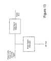
- FIG. 13is a block diagram of an example embodiment, according to the invention.
- FIG. 14is a functional block diagram of an example embodiment, according to the invention.
- FIG. 15illustrates an example implementation of the embodiment of FIG. 14 ;
- FIG. 16illustrates an example implementation of the embodiment of FIG. 14 ;
- FIGS. 17 a - bare functional block diagrams of another example embodiment, according to the invention.
- FIG. 18is a functional block diagram of another example embodiment, according to the invention.
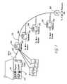
- FIG. 1is a block diagram of a typical electrical power system-based communication system 100 . It should be appreciated that system 100 may include numerous other components, well known to those skilled in the art. However, the components depicted in system 100 and shown for the purposes of clarity and brevity, while providing a proper context for the invention.
- a power company 120distributes power over its network to a power transformer 102 .
- Power transformer 102can serve several end users.
- Power transformer 102provides stepped-down voltage to an electric power meter 104 , which may be located with the end user.
- Power meter 102is coupled to various appliances 106 , 108 , and 110 , which may represent any type of residential, commercial or industrial electrical equipment.
- a telephone company 112provides telecommunication wiring over its network directly to the end user. The telecommunication wiring may be in communication with various devices, including a telephone 114 , a facsimile machine 116 , and/or a computing device 118 . Therefore, FIG. 1 provides an overview of the two separate systems or networks (i.e., telecommunications system and power system) that serve a residential, commercial or industrial end user.
- FIG. 2is a block diagram of a communication system using an electric power system to transfer data.
- the communication systemmay include numerous other components, well known to those skilled in the art, the system depicted in FIG. 2 is shown for the purposes of clarity and brevity, while providing a proper context for the invention.
- power company 120delivers electrical power (typically in the several kilovolt range) to a power transformer 102 .
- Power transformer 102steps the voltage level down (e.g., to approximately 110 volts AC or 120 volts AC) as required and provides power over power line 202 to a power meter 104 .
- power transformer 102provides electrical isolation characteristics.
- Poweris provided from power meter 104 to the residential, commercial or industrial end user via internal power wiring 208 .
- a power line interface device (PLID) 210is in communication with internal power wiring 208 .
- PIDpower line interface device
- internal power wiring 208 for a home or businesstypically supports data rates of up to 100 kilobits per second with 10 ⁇ 9 bit error rate (BER).
- PLID 210provides an interface for plain old telephone service (POTS), and data through for example a RS-232 port or Ethernet connection. Therefore, an end user may use PLID 210 to communicate data over power line 202 , via internal power wiring 208 , using telephone 114 , facsimile machine 116 and/or computer 118 , for example. Although not shown in FIG. 2 , it should be appreciated that a user can have multiple PLIDs within any particular installation.
- POTSplain old telephone service
- FIG. 3provides a basic block diagram of the components necessary to connect the medium voltage portion of the system with the low voltage portion in an example system.
- a series of power transformers 303 - 306connect various end users to a point of presence 301 via an aggregation point (AP) 302 .
- AP 302communications to centralized servers (e.g., the Internet) via a Point of Presence 301 (POP).
- POP 301may be a computing device capable of communicating with a centralized server on the Internet, for example.
- the connection between POP 301 and AP 302can be any type of communication media including fiber, copper or a wireless link.
- Each power transformer 303 - 306has an associated Power Line Bridge 307 - 310 (PLB).
- PLBs 307 - 310provide an interface between the medium voltage on the primary side of the transformer with the low voltage on the secondary side of the transformer.
- PLBs 307 - 310communicate with their respective PLIDs (e.g., PLID 210 and PLB 310 ) located on the low voltage system.
- PLBs 307 - 310employ MV couplers that prevent the medium voltage from passing to the low voltage side of the system via PLBs 307 - 310 , while still allowing communication signals to be transported between the low voltage and medium voltage systems.
- the medium voltage couplerstherefore provide the necessary isolation traditionally provided by power transformers 303 - 306 .
- the inventionis directed at a novel technique for transporting signals between the medium voltage system and the end users.
- PLCSspower line communications systems
- datamay be amplified or repeated at each transformer in both the upstream and downstream directions.
- datamay be communicated via the medium voltage power line and then communicated wirelessly to and from the customer location (e.g., using an IEEE 802 protocol) via a wireless transceiver.
- the datamay be transmitted through the distribution transformer to the customer location (e.g., with or without a repeater on the low voltage power line).
- the inventionis not limited to a particular PLCS, PLCS architecture, or topology.
- FIG. 4is a circuit diagram of a prior art coupling system 400 .
- a high-voltage cable 315is connected to a lightning arrester 402 .
- the term “high-voltage”will be used throughout to describe voltage levels on an electric power system that are higher than typically provided to the end user.
- the term “low-voltage”will be used throughout to describe voltage levels on an electric power system that are provided to the end user.
- Lightning arrester 402is connected to a ground potential 407 by means of a grounding rod 403 .
- the connection between high-voltage cable 315 and ground potential 407has a certain inductance value that may be increased by placing a ferrite core 404 around grounding rod 403 .
- lightning arrester 402typically has a capacitance value in a range of 1 to 170 picofarads (pf) (as will be discussed with reference to FIG. 5 ).
- a transformer device 406is connected in parallel with grounding rod 403 and across ferrite core 404 . Transformer device 406 acts to communicate a data signal from high-voltage cable 315 to and from transceiver 405 , while providing the necessary isolation from the high voltage carried by high-voltage cable 315 .
- Transceiver unit 405takes the data signal provided via transformer 406 and transmits and receives data signals from an end user (not shown) or a data server (not shown).
- FIG. 4suffers from many inherent problems.
- a lightning arrester devicemust be installed on both ends of high-voltage cable 315 , and thus could potentially adversely affecting the real and reactive power components provided by high-voltage cable 315 .
- the capacitive value of the lightning arrestermust be close to the high end of the available range (e.g., 170 pf) rather than to the low end of the range (e.g., 1 pf so as to ensure that a sufficient signal over a wide frequency band is provided to transceiver 405 (as discussed further with reference to FIG. 5 ).
- system 400represents a dual-pole RLC circuit, and thus exhibits significant signal degradation over each frequency interval, a large loss or a resonance, as compared to a single pole circuit.
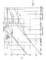
- FIG. 5provides the graphical results of SPICE (Simulation Program With Integrated Circuit Emphasis) simulation of system 100 .
- FIG. 5illustrates the limitations of the signal in the frequency domain in the prior art, as compared to the invention.
- FIG. 5illustrates the attenuation (dB) of a signal over a range of frequencies (Hz) received by transceiver 106 for various capacitive and resistive values that may be provided in system 100 , and therefore further illustrates the above-mentioned limitations in the prior art.
- a signal source with a 50 ohm internal resistanceis provided on the high-voltage cable 315 .
- the inductive value for system 100is set at 10 microhenries.
- Graphical line 501illustrates a capacitive value of 1 pf and a resistive value of 100 ohms.
- Graphical line 502illustrates a capacitive value of 1 pf and a resistive value of 1 kiloohm.
- Graphical line 503illustrates a capacitive value of 170 pf and a resistive value of 100 ohms.
- Graphical line 504illustrates a capacitive value of 100 pf and a resistive value of 1 kiloohm.
- graphical line 505illustrates the attenuation for frequencies passed by the techniques of the invention. Graphical line 505 is depicted in FIG. 5 for the purpose of comparison with lines 501 - 504 .
- graphical line 505permits a wider range of frequencies to pass with less attenuation than graphical lines 501 - 504 , over most of the frequencies.
- each of lines 501 - 502indicate that system 100 causes a large attenuation for frequencies that are less than 600 kHz.
- lines 501 - 502causes a greater attenuation than line 505 over the entire range of frequencies depicted in FIG. 5 .
- system 100uses capacitive values at the lower end of the available range (e.g., 1 pf)
- attenuation of the signalsis great and therefore undesirable.
- line 503 - 504where the capacitive values are on the higher end of the range (e.g., 100 pf)
- attenuationis great.
- line 504(170 pf and 1 kiloohm) provides less attenuation over a narrow range of frequencies
- line 505may be more beneficial for providing a better or equal attenuation over a wider range of frequencies. Accordingly, neither high nor low values for system 100 will ensure a uniform coupling in a wide frequency band. Also, as depicted with line 504 at a frequency of 4 MHz, system 100 may exhibit resonant behavior at high coupling coefficients. These variations in the frequency domain can distort the data signal, or at least require additional design considerations for system 100 including transceiver 405 , for example.
- lines 501 - 504with line 505 indicates that the dual-pole nature of the prior art circuit leads to a faster rate of coupling decay at lower frequencies. For example, as shown in FIG. 5 , from 100 kHz to approximately 2 MHz, lines 501 - 504 exhibit a 12 dB/octave. This is to be distinguished from the 6 dB/octave decay in line 505 representing the invention's single-pole characteristics.
- FIG. 6further illustrates the inadequacy of prior art system 100 by providing a graphical representation of one of prior art lines 501 - 504 in the time domain (as compared to FIG. 5 's depiction in the frequency domain).
- FIG. 6provides a depiction of the distortion that system 100 causes to a rectangular pulse with a 1 volt and a 100 nanosecond (ns) duration.
- nsnanosecond
- FIG. 6even with a generous grounding-rod inductance of 1 microhenry ( ⁇ H), the inputted rectangular pulse is significantly distorted.
- the inventionprovides much less attenuation of the inputted signal.
- any surge appearing on high-voltage line 315could damage transceiver 105 .
- the coupler of the present inventionmay be used in a transformer bypass device, a backhaul point, a repeater, or at any location at which it is desirable to couple data signals to and/or from a power line and especially a power line carrying voltages (e.g., power lines carrying a voltage above one thousand volts such as medium voltage and high voltage power lines).
- a power line carrying voltagese.g., power lines carrying a voltage above one thousand volts such as medium voltage and high voltage power lines.
- FIG. 7is a diagram of a coupler technique, according to the invention.
- FIG. 7provides a conceptual diagram of a method for coupling a data transceiver to an electrical power line.
- High-voltage cable 315is shown in FIG. 7 .
- High-voltage cablemay be a commercially available distribution cable, for example a 15 kV underground feeder available from Okonite, model Okoguard URO.
- High-voltage cable 315has a center conductor 703 .
- Center conductor 703typically is a stranded aluminum conductor with a rating capable of carrying current at medium voltage levels.
- Center conductor 703has one or more insulative covers (not shown). The insulation on center conductor 703 is surrounded by a concentric conductor 704 .
- Concentric conductor 704typically is found on underground distribution feeders, but also may be found on certain overhead distribution feeders.
- Concentric conductor 704typically does not carry high voltage, but acts as a shield to reduce the inductance caused by center conductor 703 . Concentric conductor 704 also may act to carry the neutral current back to the power source. Concentric conductor 704 is surrounded by an outer insulating sleeve (not shown). The outer insulating sleeve provides protection and insulative properties to high-voltage cable 315 . High-voltage cable 315 is assumed to be AC-terminated at its ends.
- high-voltage cable 315may be modified to facilitate the use of high-voltage cable 315 in carrying desired data signals.
- a shield gap 706has been cut in concentric conductor 704 around the entire periphery of high-voltage cable 315 .
- Shield gap 706effectively divides concentric conductor 704 into two parts.
- a transceiver 707is in communication with high-voltage cable 315 by a connection to concentric conductor 704 .
- transceiver 707may be a fiber-optic transceiver (as will be discussed further with reference to FIG. 6 ), capable of receiving and transmitting any type of data signal (e.g., radio frequency signals).
- Subscriber sideand “transformer side” will be used throughout to describe the two sides of high-voltage cable 315 relative to shield gap 706 .
- Subscriber sidewill be used to describe the portion of high-voltage cable 315 to which transceiver 707 is coupled. This is consistent with the fact that the subscriber (i.e., end user) is in communication with transceiver 707 .
- Transformer sidewill be used to describe the portion of high-voltage cable 315 to which transceiver 707 is not coupled. This is consistent with the fact that the pole-top or pad-mount transformer is coupled to the transformer side of high-voltage cable 315 .
- the ground connection 107(along with other ground connections along the length of high-voltage cable 315 ) is provided at a distance l from the subscriber side of shield gap 706 .
- High-voltage cable 315has an inductance that depends on the distance l from ground, as well as other characteristics of high-voltage cable 315 (e.g., diameter and distance from ground plane).
- Inductance Lperforms a function similar to the inductance of grounding rod 103 described with reference to FIG. 4 .
- inductance Lmay be increased.
- Increasing inductance Lmay be accomplished by placing additional ferrite cores 708 along the length of high-voltage cable 10 .
- a more complete discussion of the placement of the grounding and inductive meansis beyond the scope of the invention.
- the length distance lshould not be significantly longer than a quarter-wave-length at the highest frequency in the transmission band, so as to prevent any resonant behavior that may increase transmission attenuation. Because the input reactance of the high-voltage cable 315 is proportional to its characteristic impedance, increasing the impedance as much as practically possible ensures low attenuation at the low end of the frequency band. This is further ensured by using a relatively high ratio of the outer and inner diameters of high-voltage cable 315 , as well as by using ferrite cores 708 with high relative permeance (e.g., 8 maxwell/gilbert).
- FIG. 8is a circuit diagram 800 representing the salient properties of the components depicted in FIG. 7 .
- the subscriber side and transformer side of high-voltage cable 315may be represented by two separate impedances, R S and R T , respectively, connected in series to each other.
- inductance Lwhich represents the inductance of high-voltage cable 315 from shield gap 706 to ground 407 as discussed with reference to FIG. 7 , is placed in parallel to impedances R S and R T .
- inductance L depicted in FIG. 8may be represented in practice by an input impedance of a short piece of a shortened coaxial line.
- the signal sourcemay be represented by a voltage V S and by an internal resistance R.
- signal sourcemay be replaced by a signal load that receives a signal.
- each sidecarries half of the signal power.
- this techniqueprovides an approximately 6 dB loss per octave, as compared to the 12 db per loss octave typically found in the prior art.
- circuit 800has a single-pole characteristic at lower frequencies, because the frequency response of circuit 800 is defined by the “RL” circuit defined by R and L.
- Optimizing the internal resistance of the source (or the load)also may be considered.
- the sources internal resistancewith the resistance of the line to which it is connected (i.e., 2 W).
- the two of the couplersare intended to be included between the terminations at the two ends of the line, and if the RF attenuation of the cable in the transmission band is low, it may be desirable to adopt a reasonable trade off.
- the reflectionscan be brought to a more desirable level.
- RW
- FIG. 9provides an example of a coupler, according to the invention.
- FIG. 9illustrates the physical configuration of the inventive method, it will be appreciated that the invention may be implemented in any number of configurations (e.g., using various types of enclosures and/or various types of grounding techniques). Accordingly, it should be appreciated that FIG. 9 provides just one example of a coupler contemplated by the invention.
- high-voltage cable 315is depicted having center conductor 703 , concentric conductor 704 , outer insulating sleeve 915 , and shield gap 706 .
- a metal enclosure 901provides the needed uninterrupted way for the power current flow to back over the interrupted concentric conductor 704 .
- metal enclosure 901also provides the necessary ground connection (described as ground 407 in FIGS. 4 and 7 ), and it forms an outer shield for a piece of shortened coaxial line that may be used to provide inductive shunt impedance (described as L with reference to FIGS. 7 and 8 ).
- High-voltage cable 315also has a series of ferrite cores 708 on the outer side of high-voltage cable 315 .
- Using multiple ferrite coresincreases the impedance of subscriber side of high-voltage cable 315 with the length l (as discussed with reference to FIG. 7 ).
- ferrite coresmay increase the equivalent inductance L of the high-voltage cable 315 , which has the same effect as increasing the impedance.
- Ferrite cores 708also may provide a current transforming function. As shown in FIG. 9 , two of ferrite cores 708 have conductors wound around their perimeter to form a transformer device 902 .
- Transformer 902is coupled to a fiber optic transceiver 903 .
- Fiber optic transceiver 903may be a transmitter/receiver pair commercially available from Microwave Photonic Systems, part number MP-2320/TX (for the transmitter) and part number MP-2320/RX (for the receiver).
- Fiber optic transceiver 903is connected to transformer 902 over lines 908 and 909 .
- transformer 902acts to induce an AC current from the high voltage carried by center conductor 703 .
- the induced alternating currentis provided to fiber optic transceiver 903 via lines 908 and 909 .
- fiber optic transceiver 903may have circuitry capable of rectifying the AC voltage provided by transformer 902 to a DC voltage.
- the DC voltagemay be in a range (e.g., 12 volts) capable of powering the transmitter/receiver pair in fiber optic transceiver 903 , so as to transmit and receive data to the end user over fiber links 906 .
- fiber optic transceiver 903may have a filtering device (not shown) coupled to lines 908 and 909 so as to pass the AC current in a desired frequency range (e.g., 60 Hz using a low-pass filter).
- the data provided to and received from the end usersis carried back to a central server (not shown) from fiber optic transceiver 903 via data links 904 and 905 .
- Data links 904 and 905are in communication with concentric conductor 704 . Because concentric conductor 704 typically is not used to carry high voltage, but acts as an inductive shield for high-voltage cable 315 , data may be carried to and from the end user via concentric conductor 704 .
- fiber optic transceiver 903may have a filtering device (not shown) coupled to lines 904 and 905 , so as to pass data signals in a desired frequency range (e.g., signals well above 60 Hz using a high-pass filter), while preventing other signals from passing onto fiber optic transceiver 903 (e.g., 60 Hz power).
- a filtering devicenot shown coupled to lines 904 and 905 , so as to pass data signals in a desired frequency range (e.g., signals well above 60 Hz using a high-pass filter), while preventing other signals from passing onto fiber optic transceiver 903 (e.g., 60 Hz power).
- the inventionwas described using a fiber optic-based transceiver. Using a fiber optic transceiver provides the necessary isolation to the end user from the medium or high voltage on center conductor 703 , and therefore ensures the safety of people and equipment. However, it should be appreciated that the invention contemplates the user of other types of transceivers, for example, where such isolation is not required.
- FIG. 10illustrates several received pulse shapes for two successive pulses of opposite polarity.
- FIG. 10provides a graphical representation of the signal strength available with the invention. Pulses correspond to the range of characteristic impedances of the stub line from 600 Ohms to 2000 Ohms so as to provide minimum intersymbol interference.
- the transmitted pulseshave amplitudes of ⁇ 1V and a pulse duration of 7 ns each, with the delay between them equal to 25 ns.
- the inventionprovides less attenuation of the inputted signal, and over a smaller time interval.
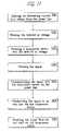
- FIG. 11is a flow diagram of a method for transporting a signal over a power line.
- an AC current voltageis induced from the power line.
- the induced AC voltageis filtered, for example, by a low-pass filter.
- a transceiver deviceis powered by the induced AC voltage.
- the signalis filtered, for example, by a high-pass filter.
- the signalis communicated between the transceiver device and the power line.
- the signalis transmitted to an end user via the transceiver device.
- the signalis received from an end user via the transceiver device.
- an example URD MV cable 10includes a center conductor 15 that carries the power signal. Surrounding the center conductor 15 is a semi-conductive layer 20 . In this example cable, the semi-conductive layer 20 is surrounded by a dielectric 25 (i.e., an insulator). A semi-conductive jacket 30 surrounds the dielectric 25 . The semi-conductive jacket 30 typically ensures, among other things, that ground potential and deadfront safety (the grounding of surfaces to which a utility company's lineman may be exposed) are maintained on the surface of the cable.
- ground potential and deadfront safetythe grounding of surfaces to which a utility company's lineman may be exposed
- a concentric conductor 40which may act as the neutral conductor for power signal transmissions, surrounds the semi-conductive jacket 30 .
- the center conductor 15is separated from the concentric conductor 40 by dielectric 25 and semiconductor 20 (which acts as a dielectric at frequencies substantially above 50/60 Hz), thereby forming a coaxial structure.
- this structuremay act as a transmission line with properties of, or similar to, a wave guide. In some embodiments, this structure has the characteristics of a conventional coaxial transmission cable.
- the cablemay terminate with an elbow on one or both ends.
- the cabletypically will terminate with an elbow.
- the underground cablewill extend up a utility pole and terminate with a “pothead” connector (not shown) for connection to an overhead MV power line (known as a Riser-Pole).
- the couplermay be designed for coupling data signals to and from a URD power cable comprising a center conductor, insulator, concentric conductor, and may also have other elements such as an external insulator.
- the URD cable described for the use with the present example embodimentcomprises those elements shown in FIG. 12 a .
- the present inventionis not limited to cables having all of those elements and may work equally as well with cables having fewer or more elements.
- This example embodiment of the present inventionmay be constructed from an existing URD cable that already is installed in the electrical power distribution network and does not require severing the center conductor of the URD cable. Although installation does not require contact with high voltages, it may be desirable to disconnect both ends of the URD cable from power to ensure safety of installation personnel.
- the couplermay be constructed during manufacturing of the cable (e.g., before the elbow or pothead are installed on the end of the cable or before installation of the cable into the electric power distribution system).
- the couplermay be installed at or near a transformer (e.g., inside the transformer enclosure).
- the URD cableis modified near both ends of the cable and adjacent the respective elbow. Consequently, the coupler may be installed on both ends of the URD cable for transmission along the cable and between underground or pad mounted transformers in an URD PLCS.
- the constructionmay be similar at both ends and therefore construction of one coupler is described herein.
- one particular embodimentmay comprise a power signal attenuator comprising a high pass filter disposed between the cable and the RF port (data port).
- the power signal attenuatormay prevent the high voltage power signal from being conducted to the RF port and thereby ensures the safety of the PLCS equipment, installation personnel, and PLCS subscribers.
- a data signal attenuatore.g., a low pass filter
- Federal regulationslimit the amount of emissions from PLCSs, which thereby reduces the amount of power that may used to communicate the data signals.
- the data signal attenuatorattenuates data signals traversing toward the end of the cable and thereby reduces emissions that would otherwise occur at the elbow (and transformer) or “pothead” termination, thereby permitting transmitting data signals with increased power.
- the data attenuatorenhances the ability to reuse frequencies (e.g., using the same frequencies to communicate data on both sides of the distribution transformer).
- the concentric conductor 40(and outer insulator if present) are removed between the elbow and a point of installation K.
- the concentric conductor 40may be detached or cut from the elbow and pulled back to point K.
- removing the concentric conductor 40 (and insulator if present)exposes the semi-conductive jacket 30 of the cable.
- the cable 1301is schematically represented by a cylinder, which represents the cable with the center conductor 15 , insulator 25 , and concentric conductor 40 .
- the cable 1301is represented by a line (e.g., such as at gap 1320 or at arrow C), which represents the cable with the concentric conductor 40 removed, but with the dielectric (insulator) 25 and center conductor 15 present.
- the cable(whether represented by a cylinder or line) may also comprise the semi-conductive jacket 30 , semi-conductive layer 20 , and outer insulator provided the cable employed has all those elements.
- a coupling line 1310 of length Dmay be installed around the cable adjacent to the point of installation K to where the concentric conductor 40 has been removed. However, there is a gap 1320 between the position to which the concentric conductor 40 has been removed (point K) and the end 1312 of the coupling line 1310 so that they may not be electrically connected across the gap. As will be discussed below, the gap 1320 may act as an insulating barrier between the outer concentric conductor 40 of cable 1301 and the coupling line 1310 . In this example embodiment, the coupling line 1310 may be in contact with the semi-conductive jacket, which extends to the concentric conductor 40 of the cable 1301 .
- the coupling line 1310is a conductive material and may have the same or similar conductive properties to those of the concentric conductor 40 and may be flexible.
- the coupling line 1310may be formed of a conductive tape, which is wound around the exposed semi-conductive jacket.
- the coupling line 1310may be formed of a mesh (or braid) that is wrapped around and attached to the cable.
- the coupling line 1310may be formed of a conductive sheath that is clamped onto or slid around the cable.
- the coupling line 1310may be formed of a plurality of cylinder shaped conductive sheaths that are all electrically and mechanically connected to remain flexible.
- the coupling line 1310may remain a portion of the concentric conductor and is formed by removing the concentric conductor at the gap 1320 , and the portion of the concentric conductor between the coupling line 1310 and the elbow.
- the coupling line 1310may be attached to earth ground at its first end 1311 .
- the coupling linemay be attached to a data cable 1350 , which may comprise one or two conductors, that is communicatively coupled to a transceiver (not shown).
- the transceivermay be HomeplugTM compatible (e.g., 1.0 or AV), or may be a cable modem (e.g., and be DOCSIS (Data Over Cable Service Interface Specification) compliant).
- the coupling line 1310may be attached to the center conductor of a coaxial cable 1350 , which forms the data cable (or data port).
- the concentric conductor of the coaxial cable 1350may be connected to the concentric conductor 40 of the cable 1301 as shown or may be connected to ground separately.
- a data attenuator 1370may be provided on the cable 1301 between the coupling line 1310 and the elbow or otherwise adjacent the coupling line 1310 and opposite the gap 1320 .
- the data attenuator 1370may be comprised of one or more magnetically permeable toroids disposed in a housing having a first and second portion coupled together via a hinge. The housing is clamped over the exposed semi-conductive jacket of the URD cable (where the concentric conductor has been removed).
- the toroidsprovide an inductance and, therefore, an impedance, to high frequencies such as data signals, and substantially no impedance to the low frequency power signal.
- the toroidshave a gap, which may be an air gap, to prevent saturation of the toroids by the power signal.
- a data attenuator 1370may not be necessary.
- the elbow, coupling line 1310 , and concentric conductor 40are all connected to ground. This may be accomplished by attaching a ground conductor 1313 to the concentric conductor 40 at the point of installation K and attaching the ground conductor 1313 to the first end 1311 of the coupling line 1310 .
- the ground conductor 1313may traverse over the coupling gap 1320 in spaced apart relation from the coupling gap as shown in FIG. 15 .
- the ground conductor 1313may be spaced apart from the coupling line 1310 as well.
- the ground conductor 1313may be an insulated wire. In other embodiments the ground conductor 1313 may be physically separated from the coupling line 1310 and gap 1320 via a spacer.
- both a spacer and insulated wiremay be used.
- the conductive path between the coupling line 1310 and ground provided, at least in part, by the ground conductor 1313may have a small amount of self-inductance.
- inductancemay be added via an inductor placed in series with the ground conductor 1313 or via toroids disposed around the ground conductor 1313 .
- the inductanceprovides an impedance to the data signals thereby reducing the amount of energy from the data signals that is conducted to ground from the end 1311 of the coupling line 1310 and ensuring more energy is reflected back down the cable 1301 along the coupling line 1310 .
- the ground conductor 1313also may traverse through the aperture of the toroids 1370 or, as shown in FIG. 15 , traverse outside the toroids 1370 to attach to the elbow to ground.
- the coupling line 1310may be installed, or the elbow (or “pothead”) attached, so that the elbow (or “pothead”) is within a certain distance (e.g., two feet) of the end 1311 of the coupling line 1310 , or more preferably within five feet thereof.
- the coupling linemay be installed inside the transformer enclosure.
- the URD cablewill act as a coaxial transmission line at the frequencies used to communicate the carrier frequencies, which may be greater than one megahertz, or more preferably greater than thirty megahertz.
- the signalswill traverse the URD cable 1301 and be contained between the center conductor and the concentric conductor 40 , which is in contrast from simply being transmitted on the concentric neutral conductor 40 .
- the data signalseventually will reach the coupling gap 1320 where the concentric conductor 40 has been removed and a first portion of the energy of the data signal will couple to the coupling line 1310 , as it propagates in the direction of arrow A, and be coupled to the coaxial cable 1350 (data port) via the coupling line 1310 .
- a second portion of the energy of the data signalsalso may not be coupled to the coupling line 1310 at the gap 1320 while traversing in the direction of arrow A.
- This second portion of the energy of the data signalswill reach the discontinuity created by the end 1311 of the coupling line 1310 where a portion of that energy of the data signals will continue towards to the elbow and another, substantial portion of the energy of the data signals may be reflected back toward the coupling gap 1320 along the coupling line 1310 .
- the physical discontinuity of a concentric conductore.g., the end 1311 of the coupling line 1310
- causes a discontinuity in the coaxial transmission linei.e., the cable
- the energy of the reflected data signalswill travel in the direction of arrow B and be coupled to the coupling line 1310 as they propagate.
- the energywill add to the first portion of the energy of the data signals traveling in the direction A that is coupled to the coaxial cable 1350 and also be coupled to the coaxial cable 1350 .
- the reflectioncauses a phase shift of the data signal by zero degrees, well known in the art as an “open stub.”
- the length D of the coupling line 1310 in this example embodimentmay be approximately one half of a wavelength of the carrier frequency. Consequently, the data signals may “shift” one half of a wave length as it propagates from the coupling gap 1320 to the end 1311 of the coupling line 1310 , where it is reflected, and then travels back toward coupling gap 1320 traversing another one half of a wavelength.
- data signals that traverse across the coupling gap 1320 to the end 1311 of the coupling line 1310 that are reflected back to the coupling gap 1320are three hundred sixty (360) degrees out of phase—or in phase—with the portion of the energy of the data signals that couples to the coaxial cable upon a first arrival at the coupling line 1310 .
- a portion of the reflected data signalis then coupled to the data cable 1350 upon arrival at the coupling gap 1320 .
- the portion of the energy of the data signals that is reflected and then coupled to the data cable 1350is additive to the portion of the energy of the data signals that couples to the data cable upon first arrival at the coupling line 1310 and thereby increases the total energy or total power of the data signals that is coupled to the coaxial cable 1350 .
- the discontinuity at the end 1311 of the coupling line 1320 that causes the reflection in combination with proper selection of the length of the coupling line 1310increases the efficiency of the coupler, or in other words, reduces the loss of the coupler.
- the discontinuity and reflection of a portion of the energy caused by the discontinuityprovide some isolation of the data signals from the power port (e.g., FIG. 13 ).
- the length D of the coupling line 1310need not be exactly one half of a wavelength of the carrier frequency. While the greatest increase in the power of the reflected data signals may occur with the coupling line 1310 having a length equal to a half of a wavelength, the reflection may still be additive and therefore increase the coupling efficiency (improve performance) even if the coupling line 1310 has a length that is less than or greater than one half of a wavelength of a carrier frequency.
- the length D of the coupling line 1310preferably may be within fifty percent of one half of a wavelength of a carrier frequency, more preferably within twenty-five percent of one half of a wavelength of a carrier frequency, or still more preferably within ten percent of one half of a wavelength of a carrier frequency (in each instance greater than or less than one half of a wavelength).
- the length D of the coupling line 1310may be less than one half of a wavelength of the highest, lowest, or center frequency of the carrier frequencies used to communicate data signals.
- the length D of the coupling line 1310preferably may be less than one hundred percent, more preferably less than ninety percent, even more preferably may be less than seventy-five percent, or still more preferably may be less than fifty percent of one half of a wavelength of a carrier frequency used to communicate the data signals.
- the data signalsmay be communicated using a range of frequencies (hereinafter the “communications frequency band”). Consequently, the length of D may be proportional to the wavelength of the highest, the lowest, the center, or another middle frequency of the communications frequency band.
- the length D of the coupling line 1310preferably may be less than one hundred percent, more preferably less than ninety percent, even more preferably may be less than seventy-five percent, or still more preferably may be less than fifty percent of one half of a wavelength of the highest, the lowest, and/or the center frequency of the carrier frequencies used to communicate the data signals
- the coupleris designed as a directional coupler (i.e., bi-directional communications in one section of the cable).
- the data signalsmay be coupled from the center conductor of the coaxial cable 1350 to the cable 1301 via connection to the coupling line 1310 .
- a first portion of the energywill propagate in the direction of arrow A (towards the elbow) and a second portion of the energy may propagate in the direction of arrow B (away from the elbow).
- this first portion of the energywill propagate from the coaxial cable 1350 to the coupling line 1310 , down the cable 1301 along the coupling line 1310 in the direction of arrow A towards the elbow.
- a portion of the energyis coupled to the center conductor of cable 1301 .
- the data signalswill reach the discontinuity created by the end 1311 of the coupling line 1310 where a portion of the energy of the data signals may continue towards to the elbow and another, substantial portion of the energy of the data signals may be reflected back toward the coupling gap 1320 along the coupling line 1310 in the direction of arrow B.
- the reflected data signalsmay travel in the direction of arrow B and be coupled to the center conductor as they propagate.
- the data signals on the center conductorreach the end 1312 of the coupling line 1310 , their energy will add with the second portion of the energy of the data signals on the center conductor of cable 1301 traveling in the direction B, which is coupled from cable 1350 .
- the first reflected portion of the energymay be additive to the second portion of the energy and thereby increase the overall power of transmitted data signals (as compared to if there was no reflected portion).
- Thisis known in the art as a reciprocal device.
- this embodimentmay have different equivalent circuit than that shown in FIG. 8 .
- the housing 1314may comprise a first and second portion that couple together (e.g., clamp together via a hinge) around the entire line.
- One end of the housingmay attach to the cable 1301 adjacent the installation point K and the other end may extend to, or nearly to, the elbow.
- the ground conductor 1313 discussed abovemay extend from the housing 1314 to be connected to ground or may attach to the housing 1314 (e.g., on the inside) and the housing 1314 may be connected to ground via a separate cable.
- the housing 1314may be formed of a conductive material having an internal and external layer of insulative material. If formed substantially of a conductive material and grounded, the conductive housing 1314 may provide reduced emissions from the data signals.
- the data attenuatorcomprises an inductor formed via one or more toroids disposed around the cable at a location where the concentric conductor is not present.
- the data attenuatormay comprise a series connection of coaxial transmission lines of different impedances. The lengths and impedances of each coaxial transmission line in the series may be designed to match a lumped element filter.
- FIG. 17schematically depicts one example of such an embodiment.
- the data attenuator 1370is comprised of a series of three transmission lines of differing impedances and, therefore, comprises four impedance discontinuities.
- a series of transmission lines of differing lengths and impedanceswill provide the equivalent of lumped elements whose impedances and types (inductive or capacitive) may be approximated using Richard's transform and Kuroda's identities.
- a length of transmission line of relatively high impedanceapproximates a series inductance and lengths of transmission line of relatively low impedance approximate a shunt capacitance.
- FIG. 17 amay be approximated with the circuit shown in FIG. 17 b , which is a fifth order Butterworth low pass filter, with the values of the capacitors and inductors being dependent on the impedances and lengths of the differing impedances in the series of data attenuator 1370 in FIG. 17 a .
- the data attenuator 1370need not be inductive or be toroids and may be any suitable attenuating mechanism.
- the coupling line 1310is connected to ground via an inductor at its second end 1312 .
- the first end 1311 of the coupling line 1310is connected to the center conductor of the coaxial cable 1350 .
- the concentric conductor of the cable 1350is connected to ground as shown.
- the inductor between ground and the end 1312 of the coupling line 1310may create a data attenuator and, therefore, may elevate the coupling line 1310 to a voltage proportional to the voltage of the data signals.
- the gap 1320 , inductor in the ground path, and other features of this embodimentmay act to create a voltage on the coupling line (relative to the center conductor) that is proportional to the data signals. This voltage may be conducted to the cable 1350 at the end 1311 of coupling line 1310 . Because this embodiment is a reciprocal device, the transmission of data signals will operate in substantially the reciprocal manner and need not be described herein.
- the inventionis directed to a method and a device for transporting a signal over a power line.
- the inventionoccasionally was described in the context underground distribution systems, but is not so limited to, regardless of any specific description in the drawing or examples set forth herein. Also, the invention was described in the context of medium voltage cables, but also includes high voltage or low voltage cables. It will be understood that the invention is not limited to use of any of the particular components or devices herein. Indeed, this invention can be used in any application that requires such a coupler. Further, the system disclosed in the invention can be used with the method of the invention or a variety of other applications.
- the couplermay be located at any desired location to couple data signals to and/or from a power line, including at a backhaul point or riser-pole or forming part of a transformer bypass device at a transformer.
- a bypass devicemay include one or more of a low voltage signal processing circuit (which may include a filter, amplifier, and other components) a low voltage modem, a processor and associated software, a router, a medium voltage modem (e.g., a HomeplugTM compatible modem or a DOCSIS compatible cable modem), and medium voltage processing circuitry.
- a backhaul device and repeatermay include some subset of these components and/or other components.
- a first cablemay connect power to the transformer, and a second cable may supply power to the next transformer. Both cables may terminate in an elbow and plug into a bushing on the transformer housing and the two cables typically are connected together inside the transformer housing.
- a separate couplermay be installed on each URD cable at the transformer (and on the opposite end of each cable).
- the datamay be received via a first coupler by a PLCS network element (such as a bypass device or simply a filter and amplifier without demodulation) and then transmitted down the second cable via the second coupler.
- the couplermay isolate the data signal from the transformer, the PLCS network element at the transformer may receive data signals in the same frequency band via both URD cables simultaneously as the data signals on the two cables will not interfere with each other. Likewise, the PLCS network element at the transformer may transmit data signals on one cable and receive data signals in the same frequency band on the other cable simultaneously as transmission on one cable will not interfere with reception on the other cable.
Landscapes
- Engineering & Computer Science (AREA)
- Computer Networks & Wireless Communication (AREA)
- Power Engineering (AREA)
- Signal Processing (AREA)
- Cable Transmission Systems, Equalization Of Radio And Reduction Of Echo (AREA)
Abstract
Description
K=(3W−W)/(W+3W)=½ (1)
K=(2W−W)/(W+2W)=⅓ (2)
It should be appreciated that the examples provided by equations (1) and (2) are just one possible configuration, and are not meant to be exclusive. In practice, for example, a value of K may be chosen with consideration of the attenuation provided by the particular characteristics of high-
Claims (69)
Priority Applications (2)
| Application Number | Priority Date | Filing Date | Title |
|---|---|---|---|
| US10/947,929US7245201B1 (en) | 2000-08-09 | 2004-09-23 | Power line coupling device and method of using the same |
| US11/265,230US7248148B2 (en) | 2000-08-09 | 2005-11-03 | Power line coupling device and method of using the same |
Applications Claiming Priority (3)
| Application Number | Priority Date | Filing Date | Title |
|---|---|---|---|
| US22403100P | 2000-08-09 | 2000-08-09 | |
| US09/924,730US6980089B1 (en) | 2000-08-09 | 2001-08-08 | Non-intrusive coupling to shielded power cable |
| US10/947,929US7245201B1 (en) | 2000-08-09 | 2004-09-23 | Power line coupling device and method of using the same |
Related Parent Applications (1)
| Application Number | Title | Priority Date | Filing Date |
|---|---|---|---|
| US09/924,730Continuation-In-PartUS6980089B1 (en) | 2000-08-09 | 2001-08-08 | Non-intrusive coupling to shielded power cable |
Related Child Applications (1)
| Application Number | Title | Priority Date | Filing Date |
|---|---|---|---|
| US11/265,230Continuation-In-PartUS7248148B2 (en) | 2000-08-09 | 2005-11-03 | Power line coupling device and method of using the same |
Publications (1)
| Publication Number | Publication Date |
|---|---|
| US7245201B1true US7245201B1 (en) | 2007-07-17 |
Family
ID=38235587
Family Applications (1)
| Application Number | Title | Priority Date | Filing Date |
|---|---|---|---|
| US10/947,929Expired - LifetimeUS7245201B1 (en) | 2000-08-09 | 2004-09-23 | Power line coupling device and method of using the same |
Country Status (1)
| Country | Link |
|---|---|
| US (1) | US7245201B1 (en) |
Cited By (15)
| Publication number | Priority date | Publication date | Assignee | Title |
|---|---|---|---|---|
| US20060291575A1 (en)* | 2003-07-03 | 2006-12-28 | Berkman William H | Power Line Communication System and Method |
| US20070242615A1 (en)* | 2006-04-12 | 2007-10-18 | Mitsubishi Electric Corporation | Transmission characteristics analyzing device and program |
| US20090128250A1 (en)* | 2007-10-16 | 2009-05-21 | France Telecom | Power line transmission |
| US20100226380A1 (en)* | 2009-03-03 | 2010-09-09 | Aboundi, Inc. | Transmission line adapter and system |
| US20100289629A1 (en)* | 2008-10-28 | 2010-11-18 | Cooper Technologies Company | Load Control Device with Two-Way Communication Capabilities |
| US8035507B2 (en) | 2008-10-28 | 2011-10-11 | Cooper Technologies Company | Method and apparatus for stimulating power line carrier injection with reactive oscillation |
| WO2012028342A1 (en)* | 2010-08-31 | 2012-03-08 | Abb Research Ltd | Power line communication filter arrangement |
| EP2665196A1 (en)* | 2012-05-14 | 2013-11-20 | LSIS Co., Ltd. | Signal coupling apparatus for power line communication |
| US20150244975A1 (en)* | 2011-07-27 | 2015-08-27 | Texas Instruments Incorporated | Power supply architectures for powered devices |
| US9746512B2 (en)* | 2008-09-22 | 2017-08-29 | Ge Aviation Systems Limited | Arc fault location detection for aircraft wiring |
| US20180013468A1 (en)* | 2016-07-11 | 2018-01-11 | Esker Technologies, LLC | Power line signal coupler |
| US10348418B1 (en) | 2014-07-22 | 2019-07-09 | Esker Technologies, LLC | Transient and spurious signal filter |
| US10417143B2 (en) | 2015-10-08 | 2019-09-17 | Esker Technologies, LLC | Apparatus and method for sending power over synchronous serial communication wiring |
| US10560154B2 (en) | 2016-07-11 | 2020-02-11 | Esker Technologies, LLC | Power line signal coupler |
| EP3221080B1 (en)* | 2014-11-19 | 2020-05-27 | Illinois Tool Works Inc. | Systems and methods for current mode communication via a weld cable |
Citations (139)
| Publication number | Priority date | Publication date | Assignee | Title |
|---|---|---|---|---|
| US1547242A (en) | 1924-04-29 | 1925-07-28 | American Telephone & Telegraph | Carrier transmission over power circuits |
| US2577731A (en) | 1942-02-20 | 1951-12-11 | Int Standard Electric Corp | High-frequency traffic system over power supply lines |
| US3369078A (en) | 1965-06-28 | 1968-02-13 | Charles R. Stradley | System for transmitting stereophonic signals over electric power lines |
| US3696383A (en) | 1970-01-17 | 1972-10-03 | Tokyo Electric Power Co | Information transmission system for metered magnitudes |
| US3701057A (en) | 1971-05-20 | 1972-10-24 | Us Navy | Broad-band lumped-element directional coupler |
| US3702460A (en) | 1971-11-30 | 1972-11-07 | John B Blose | Communications system for electric power utility |
| US3810096A (en) | 1972-09-14 | 1974-05-07 | Integrated Syst Co | Method and system for transmitting data and indicating room status |
| US3846638A (en) | 1972-10-02 | 1974-11-05 | Gen Electric | Improved coupling arrangement for power line carrier systems |
| US3895370A (en) | 1972-07-04 | 1975-07-15 | Sits Soc It Telecom Siemens | High-frequency communication system using A-C utility lines |
| US3942170A (en) | 1975-01-31 | 1976-03-02 | Westinghouse Electric Corporation | Distribution network powerline carrier communication system |
| US3962547A (en) | 1975-05-27 | 1976-06-08 | Westinghouse Electric Corporation | Repeater coupler for power line communication systems |
| US4004110A (en) | 1975-10-07 | 1977-01-18 | Westinghouse Electric Corporation | Power supply for power line carrier communication systems |
| US4016429A (en) | 1976-01-16 | 1977-04-05 | Westinghouse Electric Corporation | Power line carrier communication system for signaling customer locations through ground wire conductors |
| US4057793A (en) | 1975-10-28 | 1977-11-08 | Johnson Raymond E | Current carrier communication system |
| US4142178A (en)* | 1977-04-25 | 1979-02-27 | Westinghouse Electric Corp. | High voltage signal coupler for a distribution network power line carrier communication system |
| US4188619A (en) | 1978-08-17 | 1980-02-12 | Rockwell International Corporation | Transformer arrangement for coupling a communication signal to a three-phase power line |
| US4254402A (en) | 1979-08-17 | 1981-03-03 | Rockwell International Corporation | Transformer arrangement for coupling a communication signal to a three-phase power line |
| US4263549A (en) | 1979-10-12 | 1981-04-21 | Corcom, Inc. | Apparatus for determining differential mode and common mode noise |
| US4323882A (en) | 1980-06-02 | 1982-04-06 | General Electric Company | Method of, and apparatus for, inserting carrier frequency signal information onto distribution transformer primary winding |
| US4383243A (en) | 1978-06-08 | 1983-05-10 | Siemens Aktiengesellschaft | Powerline carrier control installation |
| US4433284A (en) | 1982-04-07 | 1984-02-21 | Rockwell International Corporation | Power line communications bypass around delta-wye transformer |
| US4481501A (en) | 1978-08-17 | 1984-11-06 | Rockwell International Corporation | Transformer arrangement for coupling a communication signal to a three-phase power line |
| US4569045A (en) | 1983-06-06 | 1986-02-04 | Eaton Corp. | 3-Wire multiplexer |
| US4636771A (en) | 1984-12-10 | 1987-01-13 | Westinghouse Electric Corp. | Power line communications terminal and interface circuit associated therewith |
| US4652855A (en) | 1984-12-05 | 1987-03-24 | Westinghouse Electric Corp. | Portable remote meter reading apparatus |
| US4668934A (en) | 1984-10-22 | 1987-05-26 | Westinghouse Electric Corp. | Receiver apparatus for three-phase power line carrier communications |
| US4675648A (en) | 1984-04-17 | 1987-06-23 | Honeywell Inc. | Passive signal coupler between power distribution systems for the transmission of data signals over the power lines |
| US4686382A (en) | 1985-08-14 | 1987-08-11 | Westinghouse Electric Corp. | Switch bypass circuit for power line communication systems |
| US4697166A (en) | 1986-08-11 | 1987-09-29 | Nippon Colin Co., Ltd. | Method and apparatus for coupling transceiver to power line carrier system |
| US4724381A (en) | 1986-02-03 | 1988-02-09 | Niagara Mohawk Power Corporation | RF antenna for transmission line sensor |
| US4745391A (en) | 1987-02-26 | 1988-05-17 | General Electric Company | Method of, and apparatus for, information communication via a power line conductor |
| US4746897A (en) | 1984-01-30 | 1988-05-24 | Westinghouse Electric Corp. | Apparatus for transmitting and receiving a power line |
| US4890089A (en) | 1988-11-25 | 1989-12-26 | Westinghouse Electric Corp. | Distribution of line carrier communications |
| US4973940A (en) | 1987-07-08 | 1990-11-27 | Colin Electronics Co., Ltd. | Optimum impedance system for coupling transceiver to power line carrier network |
| WO1992016920A1 (en) | 1991-03-16 | 1992-10-01 | Gjd Manufacturing Limited | Signalling system and method |
| US5210519A (en) | 1990-06-22 | 1993-05-11 | British Aerospace Public Limited Company | Digital data transmission |
| US5257006A (en) | 1990-09-21 | 1993-10-26 | Echelon Corporation | Method and apparatus for power line communications |
| US5351272A (en) | 1992-05-18 | 1994-09-27 | Abraham Karoly C | Communications apparatus and method for transmitting and receiving multiple modulated signals over electrical lines |
| US5412254A (en)* | 1991-12-24 | 1995-05-02 | Gec-Marconi Limited | High voltage pulse generator |
| EP0470185B1 (en) | 1989-04-28 | 1995-11-29 | ABRAHAM, Charles | Power-line communication apparatus |
| US5485040A (en) | 1991-05-10 | 1996-01-16 | Echelon Corporation | Powerline coupling network |
| US5497142A (en) | 1991-10-17 | 1996-03-05 | Electricite De France | Directional separator-coupler circuit for medium-frequency carrier currents on a low-voltage electrical line |
| US5537087A (en) | 1991-08-07 | 1996-07-16 | Mitsubishi Denki Kabushiki Kaisha | Signal discriminator |
| US5559377A (en) | 1989-04-28 | 1996-09-24 | Abraham; Charles | Transformer coupler for communication over various lines |
| US5592354A (en) | 1991-03-19 | 1997-01-07 | Nocentino, Jr.; Albert | Audio bandwidth interface apparatus for pilot wire relays |
| US5625863A (en) | 1989-04-28 | 1997-04-29 | Videocom, Inc. | Video distribution system using in-wall wiring |
| US5684450A (en) | 1992-10-22 | 1997-11-04 | Norweb Plc | Electricity distribution and/or power transmission network and filter for telecommunication over power lines |
| US5694108A (en) | 1996-05-01 | 1997-12-02 | Abb Power T&D Company Inc. | Apparatus and methods for power network coupling |
| US5705974A (en) | 1995-05-09 | 1998-01-06 | Elcom Technologies Corporation | Power line communications system and coupling circuit for power line communications system |
| US5717685A (en) | 1989-04-28 | 1998-02-10 | Abraham; Charles | Transformer coupler for communication over various lines |
| US5770996A (en) | 1996-08-30 | 1998-06-23 | Interactive Technologies, Inc. | Transformer system for power line communications |
| WO1998033258A2 (en) | 1997-01-28 | 1998-07-30 | Northern Telecom Limited | Power line transmission |
| US5818127A (en) | 1989-04-28 | 1998-10-06 | Videocom, Inc. | Transmission of FM video signals over various lines |
| US5850114A (en) | 1996-12-23 | 1998-12-15 | Froidevaux; Jean-Claude | Device for improving the quality of audio and/or video signals |
| US5856776A (en) | 1993-11-24 | 1999-01-05 | Remote Metering Systems, Ltd. | Method and apparatus for signal coupling at medium voltage in a power line carrier communications system |
| US5864284A (en) | 1997-03-06 | 1999-01-26 | Sanderson; Lelon Wayne | Apparatus for coupling radio-frequency signals to and from a cable of a power distribution network |
| US5892430A (en) | 1994-04-25 | 1999-04-06 | Foster-Miller, Inc. | Self-powered powerline sensor |
| EP0913955A2 (en) | 1994-04-21 | 1999-05-06 | Norweb Plc | Transmission network and filter therefor |
| GB2331683A (en) | 1997-11-24 | 1999-05-26 | Norweb Plc | Coupling telecommunications signal to power cables |
| US5933073A (en) | 1997-07-07 | 1999-08-03 | Abb Power T&D Company Inc. | Apparatus and methods for power network coupling |
| US5937342A (en)* | 1997-01-28 | 1999-08-10 | Dynamic Telecommunications, Inc. | Wireless local distribution system using standard power lines |
| US5949327A (en) | 1994-08-26 | 1999-09-07 | Norweb Plc | Coupling of telecommunications signals to a balanced power distribution network |
| EP0948143A2 (en) | 1998-04-03 | 1999-10-06 | Abb Research Ltd. | Method and device for signal communication over power lines |
| EP0959569A1 (en) | 1998-05-11 | 1999-11-24 | Abb Research Ltd. | Method and apparatus for signal coupling in high or middle voltage cable |
| US5994998A (en) | 1997-05-29 | 1999-11-30 | 3Com Corporation | Power transfer apparatus for concurrently transmitting data and power over data wires |
| US6014386A (en) | 1989-10-30 | 2000-01-11 | Videocom, Inc. | System and method for high speed communication of video, voice and error-free data over in-wall wiring |
| US6023106A (en) | 1994-12-02 | 2000-02-08 | Abraham; Charles | Power line circuits and adaptors for coupling carrier frequency current signals between power lines |
| US6040759A (en) | 1998-02-17 | 2000-03-21 | Sanderson; Lelon Wayne | Communication system for providing broadband data services using a high-voltage cable of a power system |
| GB2341776A (en) | 1998-03-17 | 2000-03-22 | Northern Telecom Ltd | Mains signalling transient suppression |
| US6104707A (en) | 1989-04-28 | 2000-08-15 | Videocom, Inc. | Transformer coupler for communication over various lines |
| WO2000059076A1 (en) | 1999-03-25 | 2000-10-05 | Nor.Web Dpl Limited | Signal coupler |
| WO2000060701A1 (en) | 1999-04-01 | 2000-10-12 | Nor.Web Dpl Limited | Coupling apparatus and method |
| US6144292A (en) | 1992-10-22 | 2000-11-07 | Norweb Plc | Powerline communications network employing TDMA, FDMA and/or CDMA |
| US6154488A (en)* | 1997-09-23 | 2000-11-28 | Hunt Technologies, Inc. | Low frequency bilateral communication over distributed power lines |
| US6177849B1 (en)* | 1998-11-18 | 2001-01-23 | Oneline Ag | Non-saturating, flux cancelling diplex filter for power line communications |
| WO2001008321A1 (en) | 1999-07-22 | 2001-02-01 | Siemens Aktiengesellschaft | Interface circuit for surge impedance |
| WO2001043305A1 (en) | 1999-12-08 | 2001-06-14 | Ascom Powerline Communications Ag | Coupling device |
| US6255935B1 (en) | 1998-09-14 | 2001-07-03 | Abb Research Ltd. | Coupling capacitor having an integrated connecting cable |
| US6282405B1 (en) | 1992-10-22 | 2001-08-28 | Norweb Plc | Hybrid electricity and telecommunications distribution network |
| EP0916194B1 (en) | 1996-08-01 | 2001-09-26 | Nortel Networks Limited | Power line communications |
| US6297730B1 (en) | 1998-08-14 | 2001-10-02 | Nor.Web Dpl Limited | Signal connection device for a power line telecommunication system |
| US20010038329A1 (en) | 2000-05-04 | 2001-11-08 | Paolo Diamanti | Coupling device for providing a communciations link for RF broadband data signals to a power line and method of installing same |
| US20010052843A1 (en) | 1996-11-01 | 2001-12-20 | Richard M. Wiesman | Non-invasive powerline communications system |
| DE10012235C2 (en) | 2000-03-14 | 2001-12-20 | Siemens Ag | Circuit arrangement for data transmission on the energy supply lines of an electrical energy supply network |
| US20010054953A1 (en) | 2000-04-14 | 2001-12-27 | Kline Paul A. | Digital communications utilizing medium voltage power distribution lines |
| US20020002040A1 (en) | 2000-04-19 | 2002-01-03 | Kline Paul A. | Method and apparatus for interfacing RF signals to medium voltage power lines |
| US6396392B1 (en) | 2000-05-23 | 2002-05-28 | Wire21, Inc. | High frequency network communications over various lines |
| EP1213849A1 (en) | 2000-12-11 | 2002-06-12 | Siemens Aktiengesellschaft | Method and apparatus for data communication over power line network |
| US20020097953A1 (en) | 2000-12-15 | 2002-07-25 | Kline Paul A. | Interfacing fiber optic data with electrical power systems |
| US20020105413A1 (en) | 1999-12-30 | 2002-08-08 | Ambient Corporation | Inductive coupling of a data signal to a power transmission cable |
| US20020110311A1 (en) | 2001-02-14 | 2002-08-15 | Kline Paul A. | Apparatus and method for providing a power line communication device for safe transmission of high-frequency, high-bandwidth signals over existing power distribution lines |
| US20020110310A1 (en) | 2001-02-14 | 2002-08-15 | Kline Paul A. | Method and apparatus for providing inductive coupling and decoupling of high-frequency, high-bandwidth data signals directly on and off of a high voltage power line |
| US20020109585A1 (en) | 2001-02-15 | 2002-08-15 | Sanderson Lelon Wayne | Apparatus, method and system for range extension of a data communication signal on a high voltage cable |
| US20020118101A1 (en) | 2001-02-14 | 2002-08-29 | Kline Paul A. | Data communication over a power line |
| DE10103530A1 (en) | 2001-01-26 | 2002-08-29 | Siemens Ag | Connection device for connecting a transmission device to a power supply line |
| US20020171535A1 (en) | 2001-03-29 | 2002-11-21 | Yehuda Cern | Coupling broadband modems to power lines |
| DE10119040A1 (en) | 2001-04-18 | 2002-12-05 | Siemens Ag | Data transmission system over current supply network with data signal input |
| DE10119039A1 (en) | 2001-04-18 | 2002-12-05 | Siemens Ag | Apparatus for transmitting data via electrical mains network, amplifies data signal using switched amplifier and couples into power network |
| US6515485B1 (en) | 2000-04-19 | 2003-02-04 | Phonex Broadband Corporation | Method and system for power line impedance detection and automatic impedance matching |
| US20030054793A1 (en) | 2001-08-17 | 2003-03-20 | Manis Constantine N. | Coupling between power line and customer in power line communication system |
| WO2003034608A2 (en) | 2001-10-12 | 2003-04-24 | Power Plus Communications Ag | Arrangement for connecting a powerline data transmission device or a repeater in a live low-voltage mains network |
| WO2003040732A2 (en) | 2001-11-09 | 2003-05-15 | Power Plus Communications Ag | Impedance stabilization network for determining the electromagnetic interfering radiation of a modem |
| US20030169155A1 (en) | 2000-04-14 | 2003-09-11 | Mollenkopf James Douglas | Power line communication system and method of using the same |
| US6624745B1 (en) | 2000-05-18 | 2003-09-23 | Advanced Micro Devices, Inc. | Low pass filter for a universal home network on a customer premises european installation bus |
| US20030201759A1 (en) | 2002-04-29 | 2003-10-30 | Ambient Corporation | Full duplexing for power line data communications |
| US20030201873A1 (en) | 2002-04-29 | 2003-10-30 | Ambient Corporation | High current inductive coupler and current transformer for power lines |
| US20030210135A1 (en) | 2002-03-14 | 2003-11-13 | Ambient Corporation | Protecting medium voltage inductive coupled device from electrical transients |
| US20030222748A1 (en) | 2002-05-03 | 2003-12-04 | Ambient Corporation | Construction of medium voltage power line data couplers |
| US20030222747A1 (en) | 2002-05-28 | 2003-12-04 | Amperion, Inc. | Method and device for installing and removing a current transformer on and from a current-carrying power line |
| US20030232599A1 (en) | 2000-08-24 | 2003-12-18 | Klaus Dostert | Method for transmitting high-frequency signals to low-frequency networks and corresponding system |
| US20030234713A1 (en) | 2002-06-21 | 2003-12-25 | Pridmore Charles Franklin | Power line coupling device and method of using the same |
| US20040003934A1 (en) | 2002-06-24 | 2004-01-08 | Cope Leonard David | Power line coupling device and method of using the same |
| US6686832B2 (en) | 2000-05-23 | 2004-02-03 | Satius, Inc. | High frequency network multiplexed communications over various lines |
| US20040032320A1 (en) | 2001-06-12 | 2004-02-19 | Main.Net Communications Ltd. | Information transmission over power lines |
| WO2004021600A1 (en) | 2002-08-20 | 2004-03-11 | Power Plus Communications Ag | Assembly and method for connecting a power line data transmission device to several power supply lines |
| US20040056734A1 (en) | 2001-05-18 | 2004-03-25 | Davidow Clifford A. | Medium voltage signal coupling structure for last leg power grid high-speed data network |
| US20040090284A1 (en) | 2002-10-17 | 2004-05-13 | Ambient Corporation | Arrangement of a data coupler for power line communications |
| US20040104798A1 (en) | 2002-11-26 | 2004-06-03 | Ambient Corporation | Arrangement of an inductive coupler for power line communications |
| US20040110483A1 (en) | 2002-12-10 | 2004-06-10 | Mollenkopf James Douglas | Power line communication sytem and method |
| US20040113756A1 (en) | 2002-12-10 | 2004-06-17 | Mollenkopf James Douglas | Device and method for coupling with electrical distribution network infrastructure to provide communications |
| US20040113757A1 (en) | 2002-12-10 | 2004-06-17 | White Melvin Joseph | Power line communication system and method of operating the same |
| US6753742B2 (en) | 2002-08-13 | 2004-06-22 | Korea Electro Technology Research Institute | Signal coupling apparatus for communication by medium voltage power line |
| US20040135676A1 (en) | 2002-12-10 | 2004-07-15 | Berkman William H. | Power line communication system and method of operating the same |
| US20040142599A1 (en) | 2003-01-21 | 2004-07-22 | Cope Leonard D. | Power line coupling device and method of using the same |
| US20040183619A1 (en) | 2003-03-14 | 2004-09-23 | Ameren Corporation | Capacitive couplers and methods for communicating data over an electrical power delivery system |
| US20040196144A1 (en) | 2001-10-02 | 2004-10-07 | Telkonet, Inc. | Method and apparatus for attaching power line communications to customer premises |
| US20040223617A1 (en) | 2003-05-08 | 2004-11-11 | Corcoran Kevin F. | Power line communication device and method of using the same |
| US20040227621A1 (en) | 2000-04-14 | 2004-11-18 | Cope Leonard D. | Power line communication apparatus and method of using the same |
| US20040227622A1 (en) | 2003-05-13 | 2004-11-18 | Giannini Paul M. | Device and method for communicating data signals through multiple power line conductors |
| US20050046550A1 (en) | 2001-10-02 | 2005-03-03 | Crenshaw Ralph E. | Method and apparatus for attaching power line communications to customer premises |
| US20050122092A1 (en) | 2002-06-12 | 2005-06-09 | Blasco Claret Jorge V. | Process and device for compensating the low frequency magnetic field in an inductive signal coupling unit |
| US6922135B2 (en) | 2000-05-23 | 2005-07-26 | Satius, Inc. | High frequency network multiplexed communications over various lines using multiple modulated carrier frequencies |
| US20050164666A1 (en) | 2002-10-02 | 2005-07-28 | Lang Jack A. | Communication methods and apparatus |
| US20050168326A1 (en) | 2002-12-10 | 2005-08-04 | Current Technologies, Llc | Power line repeater system and method |
| US20050194944A1 (en) | 2004-03-04 | 2005-09-08 | Folts Douglas C. | Dynamic reactive compensation system and method |
| US6980089B1 (en) | 2000-08-09 | 2005-12-27 | Current Technologies, Llc | Non-intrusive coupling to shielded power cable |
| US20060036388A1 (en) | 2004-08-04 | 2006-02-16 | Swarztrauber Sayre A | Method and system for radio-frequency signal coupling to medium tension power lines with auto-tuning device |
| US20060044076A1 (en) | 2004-09-02 | 2006-03-02 | Law Robinson P S | Serial signal injection using capacitive and transformer couplings for power line communications |
| US20060087382A1 (en) | 2004-10-25 | 2006-04-27 | Ambient Corporation | Inductive coupler for power line communications |
- 2004
- 2004-09-23USUS10/947,929patent/US7245201B1/ennot_activeExpired - Lifetime
Patent Citations (169)
| Publication number | Priority date | Publication date | Assignee | Title |
|---|---|---|---|---|
| US1547242A (en) | 1924-04-29 | 1925-07-28 | American Telephone & Telegraph | Carrier transmission over power circuits |
| US2577731A (en) | 1942-02-20 | 1951-12-11 | Int Standard Electric Corp | High-frequency traffic system over power supply lines |
| US3369078A (en) | 1965-06-28 | 1968-02-13 | Charles R. Stradley | System for transmitting stereophonic signals over electric power lines |
| US3696383A (en) | 1970-01-17 | 1972-10-03 | Tokyo Electric Power Co | Information transmission system for metered magnitudes |
| US3701057A (en) | 1971-05-20 | 1972-10-24 | Us Navy | Broad-band lumped-element directional coupler |
| US3702460A (en) | 1971-11-30 | 1972-11-07 | John B Blose | Communications system for electric power utility |
| US3895370A (en) | 1972-07-04 | 1975-07-15 | Sits Soc It Telecom Siemens | High-frequency communication system using A-C utility lines |
| US3810096A (en) | 1972-09-14 | 1974-05-07 | Integrated Syst Co | Method and system for transmitting data and indicating room status |
| US3846638A (en) | 1972-10-02 | 1974-11-05 | Gen Electric | Improved coupling arrangement for power line carrier systems |
| US3942170A (en) | 1975-01-31 | 1976-03-02 | Westinghouse Electric Corporation | Distribution network powerline carrier communication system |
| US3962547A (en) | 1975-05-27 | 1976-06-08 | Westinghouse Electric Corporation | Repeater coupler for power line communication systems |
| US4004110A (en) | 1975-10-07 | 1977-01-18 | Westinghouse Electric Corporation | Power supply for power line carrier communication systems |
| US4057793A (en) | 1975-10-28 | 1977-11-08 | Johnson Raymond E | Current carrier communication system |
| US4016429A (en) | 1976-01-16 | 1977-04-05 | Westinghouse Electric Corporation | Power line carrier communication system for signaling customer locations through ground wire conductors |
| US4142178A (en)* | 1977-04-25 | 1979-02-27 | Westinghouse Electric Corp. | High voltage signal coupler for a distribution network power line carrier communication system |
| US4383243A (en) | 1978-06-08 | 1983-05-10 | Siemens Aktiengesellschaft | Powerline carrier control installation |
| US4188619A (en) | 1978-08-17 | 1980-02-12 | Rockwell International Corporation | Transformer arrangement for coupling a communication signal to a three-phase power line |
| US4481501A (en) | 1978-08-17 | 1984-11-06 | Rockwell International Corporation | Transformer arrangement for coupling a communication signal to a three-phase power line |
| US4254402A (en) | 1979-08-17 | 1981-03-03 | Rockwell International Corporation | Transformer arrangement for coupling a communication signal to a three-phase power line |
| US4263549A (en) | 1979-10-12 | 1981-04-21 | Corcom, Inc. | Apparatus for determining differential mode and common mode noise |
| US4323882A (en) | 1980-06-02 | 1982-04-06 | General Electric Company | Method of, and apparatus for, inserting carrier frequency signal information onto distribution transformer primary winding |
| US4433284A (en) | 1982-04-07 | 1984-02-21 | Rockwell International Corporation | Power line communications bypass around delta-wye transformer |
| US4569045A (en) | 1983-06-06 | 1986-02-04 | Eaton Corp. | 3-Wire multiplexer |
| US4746897A (en) | 1984-01-30 | 1988-05-24 | Westinghouse Electric Corp. | Apparatus for transmitting and receiving a power line |
| US4675648A (en) | 1984-04-17 | 1987-06-23 | Honeywell Inc. | Passive signal coupler between power distribution systems for the transmission of data signals over the power lines |
| US4668934A (en) | 1984-10-22 | 1987-05-26 | Westinghouse Electric Corp. | Receiver apparatus for three-phase power line carrier communications |
| US4652855A (en) | 1984-12-05 | 1987-03-24 | Westinghouse Electric Corp. | Portable remote meter reading apparatus |
| US4636771A (en) | 1984-12-10 | 1987-01-13 | Westinghouse Electric Corp. | Power line communications terminal and interface circuit associated therewith |
| US4686382A (en) | 1985-08-14 | 1987-08-11 | Westinghouse Electric Corp. | Switch bypass circuit for power line communication systems |
| US4724381A (en) | 1986-02-03 | 1988-02-09 | Niagara Mohawk Power Corporation | RF antenna for transmission line sensor |
| US4697166A (en) | 1986-08-11 | 1987-09-29 | Nippon Colin Co., Ltd. | Method and apparatus for coupling transceiver to power line carrier system |
| US4745391A (en) | 1987-02-26 | 1988-05-17 | General Electric Company | Method of, and apparatus for, information communication via a power line conductor |
| US4973940A (en) | 1987-07-08 | 1990-11-27 | Colin Electronics Co., Ltd. | Optimum impedance system for coupling transceiver to power line carrier network |
| US4890089A (en) | 1988-11-25 | 1989-12-26 | Westinghouse Electric Corp. | Distribution of line carrier communications |
| US5818127A (en) | 1989-04-28 | 1998-10-06 | Videocom, Inc. | Transmission of FM video signals over various lines |
| US5717685A (en) | 1989-04-28 | 1998-02-10 | Abraham; Charles | Transformer coupler for communication over various lines |
| US6407987B1 (en) | 1989-04-28 | 2002-06-18 | Wire21, Inc. | Transformer coupler for communication over various lines |
| EP0470185B1 (en) | 1989-04-28 | 1995-11-29 | ABRAHAM, Charles | Power-line communication apparatus |
| US6104707A (en) | 1989-04-28 | 2000-08-15 | Videocom, Inc. | Transformer coupler for communication over various lines |
| US5559377A (en) | 1989-04-28 | 1996-09-24 | Abraham; Charles | Transformer coupler for communication over various lines |
| US5625863A (en) | 1989-04-28 | 1997-04-29 | Videocom, Inc. | Video distribution system using in-wall wiring |
| US6014386A (en) | 1989-10-30 | 2000-01-11 | Videocom, Inc. | System and method for high speed communication of video, voice and error-free data over in-wall wiring |
| US5210519A (en) | 1990-06-22 | 1993-05-11 | British Aerospace Public Limited Company | Digital data transmission |
| US5257006A (en) | 1990-09-21 | 1993-10-26 | Echelon Corporation | Method and apparatus for power line communications |
| WO1992016920A1 (en) | 1991-03-16 | 1992-10-01 | Gjd Manufacturing Limited | Signalling system and method |
| US5592354A (en) | 1991-03-19 | 1997-01-07 | Nocentino, Jr.; Albert | Audio bandwidth interface apparatus for pilot wire relays |
| US5485040A (en) | 1991-05-10 | 1996-01-16 | Echelon Corporation | Powerline coupling network |
| US5537087A (en) | 1991-08-07 | 1996-07-16 | Mitsubishi Denki Kabushiki Kaisha | Signal discriminator |
| US5497142A (en) | 1991-10-17 | 1996-03-05 | Electricite De France | Directional separator-coupler circuit for medium-frequency carrier currents on a low-voltage electrical line |
| US5412254A (en)* | 1991-12-24 | 1995-05-02 | Gec-Marconi Limited | High voltage pulse generator |
| US5351272A (en) | 1992-05-18 | 1994-09-27 | Abraham Karoly C | Communications apparatus and method for transmitting and receiving multiple modulated signals over electrical lines |
| US6172597B1 (en) | 1992-10-22 | 2001-01-09 | Norweb Plc | Electricity distribution and/or power transmission network and filter for telecommunication over power lines |
| US6144292A (en) | 1992-10-22 | 2000-11-07 | Norweb Plc | Powerline communications network employing TDMA, FDMA and/or CDMA |
| US5933071A (en) | 1992-10-22 | 1999-08-03 | Norweb Plc | Electricity distribution and/or power transmission network and filter for telecommunication over power lines |
| US6282405B1 (en) | 1992-10-22 | 2001-08-28 | Norweb Plc | Hybrid electricity and telecommunications distribution network |
| US5684450A (en) | 1992-10-22 | 1997-11-04 | Norweb Plc | Electricity distribution and/or power transmission network and filter for telecommunication over power lines |
| US5929750A (en) | 1992-10-22 | 1999-07-27 | Norweb Plc | Transmission network and filter therefor |
| US5856776A (en) | 1993-11-24 | 1999-01-05 | Remote Metering Systems, Ltd. | Method and apparatus for signal coupling at medium voltage in a power line carrier communications system |
| EP0913955A2 (en) | 1994-04-21 | 1999-05-06 | Norweb Plc | Transmission network and filter therefor |
| US5892430A (en) | 1994-04-25 | 1999-04-06 | Foster-Miller, Inc. | Self-powered powerline sensor |
| US5949327A (en) | 1994-08-26 | 1999-09-07 | Norweb Plc | Coupling of telecommunications signals to a balanced power distribution network |
| US6023106A (en) | 1994-12-02 | 2000-02-08 | Abraham; Charles | Power line circuits and adaptors for coupling carrier frequency current signals between power lines |
| US5705974A (en) | 1995-05-09 | 1998-01-06 | Elcom Technologies Corporation | Power line communications system and coupling circuit for power line communications system |
| US5694108A (en) | 1996-05-01 | 1997-12-02 | Abb Power T&D Company Inc. | Apparatus and methods for power network coupling |
| US6785532B1 (en) | 1996-08-01 | 2004-08-31 | Nortel Networks Limited | Power line communications |
| EP0916194B1 (en) | 1996-08-01 | 2001-09-26 | Nortel Networks Limited | Power line communications |
| US5770996A (en) | 1996-08-30 | 1998-06-23 | Interactive Technologies, Inc. | Transformer system for power line communications |
| US20010052843A1 (en) | 1996-11-01 | 2001-12-20 | Richard M. Wiesman | Non-invasive powerline communications system |
| US5850114A (en) | 1996-12-23 | 1998-12-15 | Froidevaux; Jean-Claude | Device for improving the quality of audio and/or video signals |
| US5937342A (en)* | 1997-01-28 | 1999-08-10 | Dynamic Telecommunications, Inc. | Wireless local distribution system using standard power lines |
| WO1998033258A2 (en) | 1997-01-28 | 1998-07-30 | Northern Telecom Limited | Power line transmission |
| US5864284A (en) | 1997-03-06 | 1999-01-26 | Sanderson; Lelon Wayne | Apparatus for coupling radio-frequency signals to and from a cable of a power distribution network |
| US5994998A (en) | 1997-05-29 | 1999-11-30 | 3Com Corporation | Power transfer apparatus for concurrently transmitting data and power over data wires |
| US6140911A (en) | 1997-05-29 | 2000-10-31 | 3Com Corporation | Power transfer apparatus for concurrently transmitting data and power over data wires |
| US5933073A (en) | 1997-07-07 | 1999-08-03 | Abb Power T&D Company Inc. | Apparatus and methods for power network coupling |
| US6154488A (en)* | 1997-09-23 | 2000-11-28 | Hunt Technologies, Inc. | Low frequency bilateral communication over distributed power lines |
| GB2331683A (en) | 1997-11-24 | 1999-05-26 | Norweb Plc | Coupling telecommunications signal to power cables |
| US6040759A (en) | 1998-02-17 | 2000-03-21 | Sanderson; Lelon Wayne | Communication system for providing broadband data services using a high-voltage cable of a power system |
| GB2341776A (en) | 1998-03-17 | 2000-03-22 | Northern Telecom Ltd | Mains signalling transient suppression |
| EP0948143A2 (en) | 1998-04-03 | 1999-10-06 | Abb Research Ltd. | Method and device for signal communication over power lines |
| EP0959569A1 (en) | 1998-05-11 | 1999-11-24 | Abb Research Ltd. | Method and apparatus for signal coupling in high or middle voltage cable |
| US6297730B1 (en) | 1998-08-14 | 2001-10-02 | Nor.Web Dpl Limited | Signal connection device for a power line telecommunication system |
| US6255935B1 (en) | 1998-09-14 | 2001-07-03 | Abb Research Ltd. | Coupling capacitor having an integrated connecting cable |
| US6177849B1 (en)* | 1998-11-18 | 2001-01-23 | Oneline Ag | Non-saturating, flux cancelling diplex filter for power line communications |
| WO2000059076A1 (en) | 1999-03-25 | 2000-10-05 | Nor.Web Dpl Limited | Signal coupler |
| WO2000060701A1 (en) | 1999-04-01 | 2000-10-12 | Nor.Web Dpl Limited | Coupling apparatus and method |
| WO2001008321A1 (en) | 1999-07-22 | 2001-02-01 | Siemens Aktiengesellschaft | Interface circuit for surge impedance |
| WO2001043305A1 (en) | 1999-12-08 | 2001-06-14 | Ascom Powerline Communications Ag | Coupling device |
| US6897764B2 (en)* | 1999-12-30 | 2005-05-24 | Ambient Corporation | Inductive coupling of a data signal for a power transmission cable |
| US6452482B1 (en) | 1999-12-30 | 2002-09-17 | Ambient Corporation | Inductive coupling of a data signal to a power transmission cable |
| US20030160684A1 (en) | 1999-12-30 | 2003-08-28 | Ambient Corporation | Inductive coupling of a data signal for a power transmission cable |
| US6646447B2 (en) | 1999-12-30 | 2003-11-11 | Ambient Corporation | Identifying one of a plurality of wires of a power transmission cable |
| US20020105413A1 (en) | 1999-12-30 | 2002-08-08 | Ambient Corporation | Inductive coupling of a data signal to a power transmission cable |
| DE10012235C2 (en) | 2000-03-14 | 2001-12-20 | Siemens Ag | Circuit arrangement for data transmission on the energy supply lines of an electrical energy supply network |
| US20040227621A1 (en) | 2000-04-14 | 2004-11-18 | Cope Leonard D. | Power line communication apparatus and method of using the same |
| US6958680B2 (en) | 2000-04-14 | 2005-10-25 | Current Technologies, Llc | Power line communication system and method of using the same |
| US6965302B2 (en) | 2000-04-14 | 2005-11-15 | Current Technologies, Llc | Power line communication system and method of using the same |
| US20030169155A1 (en) | 2000-04-14 | 2003-09-11 | Mollenkopf James Douglas | Power line communication system and method of using the same |
| US20010054953A1 (en) | 2000-04-14 | 2001-12-27 | Kline Paul A. | Digital communications utilizing medium voltage power distribution lines |
| US6998962B2 (en) | 2000-04-14 | 2006-02-14 | Current Technologies, Llc | Power line communication apparatus and method of using the same |
| US20020002040A1 (en) | 2000-04-19 | 2002-01-03 | Kline Paul A. | Method and apparatus for interfacing RF signals to medium voltage power lines |
| US6515485B1 (en) | 2000-04-19 | 2003-02-04 | Phonex Broadband Corporation | Method and system for power line impedance detection and automatic impedance matching |
| US6683531B2 (en) | 2000-05-04 | 2004-01-27 | Trench Limited | Coupling device for providing a communications link for RF broadband data signals to a power line and method for installing same |
| US20010038329A1 (en) | 2000-05-04 | 2001-11-08 | Paolo Diamanti | Coupling device for providing a communciations link for RF broadband data signals to a power line and method of installing same |
| US6624745B1 (en) | 2000-05-18 | 2003-09-23 | Advanced Micro Devices, Inc. | Low pass filter for a universal home network on a customer premises european installation bus |
| US6922135B2 (en) | 2000-05-23 | 2005-07-26 | Satius, Inc. | High frequency network multiplexed communications over various lines using multiple modulated carrier frequencies |
| US6686832B2 (en) | 2000-05-23 | 2004-02-03 | Satius, Inc. | High frequency network multiplexed communications over various lines |
| US6396392B1 (en) | 2000-05-23 | 2002-05-28 | Wire21, Inc. | High frequency network communications over various lines |
| US6980089B1 (en) | 2000-08-09 | 2005-12-27 | Current Technologies, Llc | Non-intrusive coupling to shielded power cable |
| US20030232599A1 (en) | 2000-08-24 | 2003-12-18 | Klaus Dostert | Method for transmitting high-frequency signals to low-frequency networks and corresponding system |
| EP1213849A1 (en) | 2000-12-11 | 2002-06-12 | Siemens Aktiengesellschaft | Method and apparatus for data communication over power line network |
| US20020097953A1 (en) | 2000-12-15 | 2002-07-25 | Kline Paul A. | Interfacing fiber optic data with electrical power systems |
| DE10103530A1 (en) | 2001-01-26 | 2002-08-29 | Siemens Ag | Connection device for connecting a transmission device to a power supply line |
| US6933835B2 (en) | 2001-02-14 | 2005-08-23 | Current Technologies, Llc | Data communication over a power line |
| US20020110310A1 (en) | 2001-02-14 | 2002-08-15 | Kline Paul A. | Method and apparatus for providing inductive coupling and decoupling of high-frequency, high-bandwidth data signals directly on and off of a high voltage power line |
| US20020110311A1 (en) | 2001-02-14 | 2002-08-15 | Kline Paul A. | Apparatus and method for providing a power line communication device for safe transmission of high-frequency, high-bandwidth signals over existing power distribution lines |
| US6950567B2 (en) | 2001-02-14 | 2005-09-27 | Current Technologies, Llc | Method and apparatus for providing inductive coupling and decoupling of high-frequency, high-bandwidth data signals directly on and off of a high voltage power line |
| US7042351B2 (en) | 2001-02-14 | 2006-05-09 | Current Technologies, Llc | Data communication over a power line |
| US20020118101A1 (en) | 2001-02-14 | 2002-08-29 | Kline Paul A. | Data communication over a power line |
| US20020121963A1 (en) | 2001-02-14 | 2002-09-05 | Kline Paul A. | Data communication over a power line |
| US20020154000A1 (en) | 2001-02-14 | 2002-10-24 | Kline Paul A. | Data communication over a power line |
| US7046882B2 (en) | 2001-02-14 | 2006-05-16 | Current Technologies, Llc | Power line communication system and method |
| US20020109585A1 (en) | 2001-02-15 | 2002-08-15 | Sanderson Lelon Wayne | Apparatus, method and system for range extension of a data communication signal on a high voltage cable |
| US20060079198A1 (en) | 2001-02-15 | 2006-04-13 | Sanderson Lelon W | Apparatus, method and system for range extension of a data communication signal on a high voltage cable |
| US20020171535A1 (en) | 2001-03-29 | 2002-11-21 | Yehuda Cern | Coupling broadband modems to power lines |
| US6809633B2 (en) | 2001-03-29 | 2004-10-26 | Ambient Corporation | Coupling broadband modems to power lines |
| DE10119040A1 (en) | 2001-04-18 | 2002-12-05 | Siemens Ag | Data transmission system over current supply network with data signal input |
| DE10119039A1 (en) | 2001-04-18 | 2002-12-05 | Siemens Ag | Apparatus for transmitting data via electrical mains network, amplifies data signal using switched amplifier and couples into power network |
| US20040056734A1 (en) | 2001-05-18 | 2004-03-25 | Davidow Clifford A. | Medium voltage signal coupling structure for last leg power grid high-speed data network |
| US20040032320A1 (en) | 2001-06-12 | 2004-02-19 | Main.Net Communications Ltd. | Information transmission over power lines |
| US20030054793A1 (en) | 2001-08-17 | 2003-03-20 | Manis Constantine N. | Coupling between power line and customer in power line communication system |
| US20040196144A1 (en) | 2001-10-02 | 2004-10-07 | Telkonet, Inc. | Method and apparatus for attaching power line communications to customer premises |
| US20050046550A1 (en) | 2001-10-02 | 2005-03-03 | Crenshaw Ralph E. | Method and apparatus for attaching power line communications to customer premises |
| WO2003034608A2 (en) | 2001-10-12 | 2003-04-24 | Power Plus Communications Ag | Arrangement for connecting a powerline data transmission device or a repeater in a live low-voltage mains network |
| WO2003040732A2 (en) | 2001-11-09 | 2003-05-15 | Power Plus Communications Ag | Impedance stabilization network for determining the electromagnetic interfering radiation of a modem |
| US20030210135A1 (en) | 2002-03-14 | 2003-11-13 | Ambient Corporation | Protecting medium voltage inductive coupled device from electrical transients |
| US7061370B2 (en) | 2002-04-29 | 2006-06-13 | Ambient Corporation | High current inductive coupler and current transformer for power lines |
| US20030201759A1 (en) | 2002-04-29 | 2003-10-30 | Ambient Corporation | Full duplexing for power line data communications |
| US20030201873A1 (en) | 2002-04-29 | 2003-10-30 | Ambient Corporation | High current inductive coupler and current transformer for power lines |
| US20030222748A1 (en) | 2002-05-03 | 2003-12-04 | Ambient Corporation | Construction of medium voltage power line data couplers |
| US20030222747A1 (en) | 2002-05-28 | 2003-12-04 | Amperion, Inc. | Method and device for installing and removing a current transformer on and from a current-carrying power line |
| US20050122092A1 (en) | 2002-06-12 | 2005-06-09 | Blasco Claret Jorge V. | Process and device for compensating the low frequency magnetic field in an inductive signal coupling unit |
| US7102478B2 (en) | 2002-06-21 | 2006-09-05 | Current Technologies, Llc | Power line coupling device and method of using the same |
| US20030234713A1 (en) | 2002-06-21 | 2003-12-25 | Pridmore Charles Franklin | Power line coupling device and method of using the same |
| US20040003934A1 (en) | 2002-06-24 | 2004-01-08 | Cope Leonard David | Power line coupling device and method of using the same |
| US6982611B2 (en) | 2002-06-24 | 2006-01-03 | Current Technologies, Llc | Power line coupling device and method of using the same |
| US6753742B2 (en) | 2002-08-13 | 2004-06-22 | Korea Electro Technology Research Institute | Signal coupling apparatus for communication by medium voltage power line |
| WO2004021600A1 (en) | 2002-08-20 | 2004-03-11 | Power Plus Communications Ag | Assembly and method for connecting a power line data transmission device to several power supply lines |
| US20050164666A1 (en) | 2002-10-02 | 2005-07-28 | Lang Jack A. | Communication methods and apparatus |
| US20040090284A1 (en) | 2002-10-17 | 2004-05-13 | Ambient Corporation | Arrangement of a data coupler for power line communications |
| US6844810B2 (en) | 2002-10-17 | 2005-01-18 | Ambient Corporation | Arrangement of a data coupler for power line communications |
| US6975210B2 (en) | 2002-11-26 | 2005-12-13 | Ambient Corporation | Arrangement of an inductive coupler for power line communications |
| US20040104798A1 (en) | 2002-11-26 | 2004-06-03 | Ambient Corporation | Arrangement of an inductive coupler for power line communications |
| US20040135676A1 (en) | 2002-12-10 | 2004-07-15 | Berkman William H. | Power line communication system and method of operating the same |
| US20040110483A1 (en) | 2002-12-10 | 2004-06-10 | Mollenkopf James Douglas | Power line communication sytem and method |
| US6980090B2 (en) | 2002-12-10 | 2005-12-27 | Current Technologies, Llc | Device and method for coupling with electrical distribution network infrastructure to provide communications |
| US20050168326A1 (en) | 2002-12-10 | 2005-08-04 | Current Technologies, Llc | Power line repeater system and method |
| US6965303B2 (en) | 2002-12-10 | 2005-11-15 | Current Technologies, Llc | Power line communication system and method |
| US20040113757A1 (en) | 2002-12-10 | 2004-06-17 | White Melvin Joseph | Power line communication system and method of operating the same |
| US20040113756A1 (en) | 2002-12-10 | 2004-06-17 | Mollenkopf James Douglas | Device and method for coupling with electrical distribution network infrastructure to provide communications |
| US20040142599A1 (en) | 2003-01-21 | 2004-07-22 | Cope Leonard D. | Power line coupling device and method of using the same |
| US7046124B2 (en) | 2003-01-21 | 2006-05-16 | Current Technologies, Llc | Power line coupling device and method of using the same |
| US20040183619A1 (en) | 2003-03-14 | 2004-09-23 | Ameren Corporation | Capacitive couplers and methods for communicating data over an electrical power delivery system |
| US20040223617A1 (en) | 2003-05-08 | 2004-11-11 | Corcoran Kevin F. | Power line communication device and method of using the same |
| US20040227622A1 (en) | 2003-05-13 | 2004-11-18 | Giannini Paul M. | Device and method for communicating data signals through multiple power line conductors |
| US20050194944A1 (en) | 2004-03-04 | 2005-09-08 | Folts Douglas C. | Dynamic reactive compensation system and method |
| US20060036388A1 (en) | 2004-08-04 | 2006-02-16 | Swarztrauber Sayre A | Method and system for radio-frequency signal coupling to medium tension power lines with auto-tuning device |
| US20060044076A1 (en) | 2004-09-02 | 2006-03-02 | Law Robinson P S | Serial signal injection using capacitive and transformer couplings for power line communications |
| US20060087382A1 (en) | 2004-10-25 | 2006-04-27 | Ambient Corporation | Inductive coupler for power line communications |
Non-Patent Citations (17)
| Title |
|---|
| "Centralized Commercial Building Applications with the Lonworks(R) PLT-21 Power Line Transceiver", Lonworks Engineering Bulletin, Echelon, (Apr. 1997), 1-22. |
| "Demand Side Management with LONWORKS(R) Power Line Transceivers", LONWORKS Engineering Bulletin, (Dec. 1996), 1-36. |
| "EMETCON Automated Distribution System", ABB Power T & D Company, Inc, (Jan. 1990), 1-14. |
| "IEEE Guide for Power-Line Carrier Applications, ANS/IEEE Std 643-1980", The Institute of Electrical and Electronics Engineers, Inc., (1980), 1-80. |
| "Intellon Corporation Test Summary for Transformerless Coupler Study", Intellon No News Wires, DOT/NHTSA Order No. DTNH22-98-P-07632, (Dec. 24, 1998), 1-18. |
| "Signalling on Low-Voltage Electrical Installations in the Frequency Band 3kHz to 148.5kHz-Part 4: Filters at the Interface of the Indoor and Outdoor Electricity Network", CLC SC 105A (Secretariat), (May 1992), 1-11. |
| "Summary of an IEEE Guide for Power-Line Carrier Applications", IEEE Transactions on Power Apparatus and Systems, (Nov./DEc. 1980),2334-2337. |
| "Centralized Commercial Building Applications with the Lonworks® PLT-21 Power Line Transceiver", Lonworks Engineering Bulletin, Echelon, (Apr. 1997), 1-22. |
| "Demand Side Management with LONWORKS® Power Line Transceivers", LONWORKS Engineering Bulletin, (Dec. 1996), 1-36. |
| Abraham, K C., et al., "A Novel High-Speed PLC Communication Modem", IEEE TRansactions on Power Delivery, (Oct. 1992), 1760-1768. |
| Barstow, J M., "A Carrier Telephone System for Rural Service", AIEE Transactions, (1947),301-307. |
| Chang, SS L., "Power-Line Carrier", Fundamentals Handbook of Electrical and Computer Engineering, Volume II-Communication, Control, DEvices and Systems, (1983),617-627. |
| Coakley, N G., et al., "Real-Time Control of a Servosytem Using the Inverter-Fed Power Lines to Communicate Sensor Feedback", IEEE Transactions on Industrial Electronics, (1999),360-369. |
| Hasler, E F., et al., "Communication Systems Using Bundle Conductor Overhead Power Lines", IEEE Transactions on Power Apparatus and Systems, (Mar./Apr. 1975), 344-349. |
| Lim, C K., et al., "Development of a Test Bed for High-Speed Power Line Communications", School of Electrical and Electronic Engineering, Nanyang Technological University, Singapore, IEEE, (2000),451-456. |
| Liu, E , et al., "Broadband Characterization of Indoor Powerline Channel", Communications Laboratory, Helsinki University of Technology, Finland [presented at the 2004 International Symposium on PowerLine Communications and its Applications, Zaragoza, Spain, (Mar. 31-Apr. 2, 2004). |
| Naredo, J L., et al., "Design of Power Line Carrier Systems on Multitransposed Delta Transmission Lines", IEEE Transactions on Power Delivery, (1991),952-958. |
Cited By (21)
| Publication number | Priority date | Publication date | Assignee | Title |
|---|---|---|---|---|
| US20060291575A1 (en)* | 2003-07-03 | 2006-12-28 | Berkman William H | Power Line Communication System and Method |
| US20070242615A1 (en)* | 2006-04-12 | 2007-10-18 | Mitsubishi Electric Corporation | Transmission characteristics analyzing device and program |
| US7830819B2 (en)* | 2006-04-12 | 2010-11-09 | Mitsubishi Electric Corporation | Transmission characteristics analyzing device and program |
| US20090128250A1 (en)* | 2007-10-16 | 2009-05-21 | France Telecom | Power line transmission |
| US7839012B2 (en)* | 2007-10-16 | 2010-11-23 | France Telecom | Power line transmission |
| US9746512B2 (en)* | 2008-09-22 | 2017-08-29 | Ge Aviation Systems Limited | Arc fault location detection for aircraft wiring |
| US20100289629A1 (en)* | 2008-10-28 | 2010-11-18 | Cooper Technologies Company | Load Control Device with Two-Way Communication Capabilities |
| US8035507B2 (en) | 2008-10-28 | 2011-10-11 | Cooper Technologies Company | Method and apparatus for stimulating power line carrier injection with reactive oscillation |
| US20100226380A1 (en)* | 2009-03-03 | 2010-09-09 | Aboundi, Inc. | Transmission line adapter and system |
| US8155143B2 (en)* | 2009-03-03 | 2012-04-10 | Aboundi, Inc. | Transmission line adapter and system |
| WO2012028342A1 (en)* | 2010-08-31 | 2012-03-08 | Abb Research Ltd | Power line communication filter arrangement |
| US20150244975A1 (en)* | 2011-07-27 | 2015-08-27 | Texas Instruments Incorporated | Power supply architectures for powered devices |
| US9549148B2 (en)* | 2011-07-27 | 2017-01-17 | Texas Instruments Incorporated | Power supply architectures for powered devices |
| EP2665196A1 (en)* | 2012-05-14 | 2013-11-20 | LSIS Co., Ltd. | Signal coupling apparatus for power line communication |
| US9396868B2 (en) | 2012-05-14 | 2016-07-19 | Lsis Co., Ltd. | Signal coupling apparatus for power line communication |
| US10348418B1 (en) | 2014-07-22 | 2019-07-09 | Esker Technologies, LLC | Transient and spurious signal filter |
| EP3221080B1 (en)* | 2014-11-19 | 2020-05-27 | Illinois Tool Works Inc. | Systems and methods for current mode communication via a weld cable |
| US10417143B2 (en) | 2015-10-08 | 2019-09-17 | Esker Technologies, LLC | Apparatus and method for sending power over synchronous serial communication wiring |
| US20180013468A1 (en)* | 2016-07-11 | 2018-01-11 | Esker Technologies, LLC | Power line signal coupler |
| US10128906B2 (en)* | 2016-07-11 | 2018-11-13 | Esker Technologies, LLC | Power line signal coupler |
| US10560154B2 (en) | 2016-07-11 | 2020-02-11 | Esker Technologies, LLC | Power line signal coupler |
Similar Documents
| Publication | Publication Date | Title |
|---|---|---|
| US7248148B2 (en) | Power line coupling device and method of using the same | |
| US6980089B1 (en) | Non-intrusive coupling to shielded power cable | |
| US7224243B2 (en) | Power line coupling device and method of using the same | |
| US7046124B2 (en) | Power line coupling device and method of using the same | |
| EP1350329B1 (en) | Apparatus and method of enabling communication of data signal via a power transmission cable. | |
| KR100806683B1 (en) | High frequency network communication device through multiple lines | |
| US7245201B1 (en) | Power line coupling device and method of using the same | |
| US7307512B2 (en) | Power line coupling device and method of use | |
| AU2001259563A1 (en) | Inductive coupling of a data signal to a power transmission cable | |
| EA011663B1 (en) | Inductive coupler for power line communications | |
| AU2006202255B2 (en) | Inductive coupling of a data signal to a power transmission cable | |
| AU2006202254B2 (en) | Inductive coupling of a data signal to a power transmission cable |
Legal Events
| Date | Code | Title | Description |
|---|---|---|---|
| AS | Assignment | Owner name:CURRENT TECHNOLOGIES, LLC, MARYLAND Free format text:ASSIGNMENT OF ASSIGNORS INTEREST;ASSIGNORS:GIDGE, BRETT D.;RADTKE, WILLIAM O.;REEL/FRAME:017765/0575;SIGNING DATES FROM 20060226 TO 20060407 | |
| AS | Assignment | Owner name:CURRENT TECHNOLOGIES, LLC, MARYLAND Free format text:ASSIGNMENT OF ASSIGNORS INTEREST;ASSIGNOR:DICKEY, SERGEY L.;REEL/FRAME:017801/0115 Effective date:20060119 | |
| AS | Assignment | Owner name:CURRENT TECHNOLOGIES, LLC, MARYLAND Free format text:ASSIGNMENT OF ASSIGNORS INTEREST;ASSIGNOR:KLINE, PAUL A.;REEL/FRAME:018009/0937 Effective date:20060615 | |
| AS | Assignment | Owner name:AP CURRENT HOLDINGS, LLC, PENNSYLVANIA Free format text:SECURITY AGREEMENT;ASSIGNOR:CURRENT TECHNOLOGIES, LLC;REEL/FRAME:020518/0001 Effective date:20080129 Owner name:AP CURRENT HOLDINGS, LLC,PENNSYLVANIA Free format text:SECURITY AGREEMENT;ASSIGNOR:CURRENT TECHNOLOGIES, LLC;REEL/FRAME:020518/0001 Effective date:20080129 | |
| AS | Assignment | Owner name:CURRENT TECHNOLOGIES, LLC, MARYLAND Free format text:RELEASE BY SECURED PARTY;ASSIGNOR:AP CURRENT HOLDINGS, LLC;REEL/FRAME:021096/0131 Effective date:20080516 Owner name:CURRENT TECHNOLOGIES, LLC,MARYLAND Free format text:RELEASE BY SECURED PARTY;ASSIGNOR:AP CURRENT HOLDINGS, LLC;REEL/FRAME:021096/0131 Effective date:20080516 | |
| FEPP | Fee payment procedure | Free format text:PAYOR NUMBER ASSIGNED (ORIGINAL EVENT CODE: ASPN); ENTITY STATUS OF PATENT OWNER: LARGE ENTITY | |
| REMI | Maintenance fee reminder mailed | ||
| LAPS | Lapse for failure to pay maintenance fees | ||
| REIN | Reinstatement after maintenance fee payment confirmed | ||
| FP | Lapsed due to failure to pay maintenance fee | Effective date:20110717 | |
| FEPP | Fee payment procedure | Free format text:PETITION RELATED TO MAINTENANCE FEES FILED (ORIGINAL EVENT CODE: PMFP); ENTITY STATUS OF PATENT OWNER: LARGE ENTITY Free format text:PETITION RELATED TO MAINTENANCE FEES GRANTED (ORIGINAL EVENT CODE: PMFG); ENTITY STATUS OF PATENT OWNER: LARGE ENTITY Free format text:PAT HOLDER CLAIMS SMALL ENTITY STATUS, ENTITY STATUS SET TO SMALL (ORIGINAL EVENT CODE: LTOS); ENTITY STATUS OF PATENT OWNER: LARGE ENTITY | |
| FEPP | Fee payment procedure | Free format text:PAYER NUMBER DE-ASSIGNED (ORIGINAL EVENT CODE: RMPN); ENTITY STATUS OF PATENT OWNER: LARGE ENTITY Free format text:PAYOR NUMBER ASSIGNED (ORIGINAL EVENT CODE: ASPN); ENTITY STATUS OF PATENT OWNER: LARGE ENTITY | |
| FPAY | Fee payment | Year of fee payment:4 | |
| PRDP | Patent reinstated due to the acceptance of a late maintenance fee | Effective date:20120206 | |
| STCF | Information on status: patent grant | Free format text:PATENTED CASE | |
| SULP | Surcharge for late payment | ||
| AS | Assignment | Owner name:SUBAUDITION WIRELESS LLC, DELAWARE Free format text:ASSIGNMENT OF ASSIGNORS INTEREST;ASSIGNOR:CURRENT TECHNOLOGIES, LLC;REEL/FRAME:027923/0572 Effective date:20120228 | |
| FEPP | Fee payment procedure | Free format text:PAT HOLDER NO LONGER CLAIMS SMALL ENTITY STATUS, ENTITY STATUS SET TO UNDISCOUNTED (ORIGINAL EVENT CODE: STOL); ENTITY STATUS OF PATENT OWNER: LARGE ENTITY | |
| REFU | Refund | Free format text:REFUND - PAYMENT OF MAINTENANCE FEE, 8TH YR, SMALL ENTITY (ORIGINAL EVENT CODE: R2552); ENTITY STATUS OF PATENT OWNER: LARGE ENTITY | |
| FPAY | Fee payment | Year of fee payment:8 | |
| AS | Assignment | Owner name:CHEMTRON RESEARCH LLC, DELAWARE Free format text:MERGER;ASSIGNOR:SUBAUDITION WIRELESS LLC;REEL/FRAME:037404/0508 Effective date:20150826 | |
| MAFP | Maintenance fee payment | Free format text:PAYMENT OF MAINTENANCE FEE, 12TH YEAR, LARGE ENTITY (ORIGINAL EVENT CODE: M1553); ENTITY STATUS OF PATENT OWNER: LARGE ENTITY Year of fee payment:12 | |
| AS | Assignment | Owner name:INTELLECTUAL VENTURES ASSETS 130 LLC, DELAWARE Free format text:ASSIGNMENT OF ASSIGNORS INTEREST;ASSIGNOR:CHEMTRON RESEARCH LLC;REEL/FRAME:050885/0827 Effective date:20191030 | |
| AS | Assignment | Owner name:COMMWORKS SOLUTIONS, LLC, GEORGIA Free format text:ASSIGNMENT OF ASSIGNORS INTEREST;ASSIGNOR:INTELLECTUAL VENTURES ASSETS 130 LLC;REEL/FRAME:051463/0026 Effective date:20191115 | |
| AS | Assignment | Owner name:UNWIRED SOLUTIONS, INC., CALIFORNIA Free format text:LICENSE;ASSIGNOR:COMMWORKS SOLUTIONS, LLC;REEL/FRAME:054443/0958 Effective date:20200918 | |
| AS | Assignment | Owner name:UNWIRED BROADBAND, INC., CALIFORNIA Free format text:CORRECTIVE ASSIGNMENT TO CORRECT THE ASSIGNEE NAME PREVIOUSLY RECORDED AT REEL: 054443 FRAME: 0958. ASSIGNOR(S) HEREBY CONFIRMS THE LICENSE;ASSIGNOR:COMMWORKS SOLUTIONS, LLC;REEL/FRAME:056981/0631 Effective date:20200918 Owner name:UNWIRED BROADBAND, INC., CALIFORNIA Free format text:CORRECTIVE ASSIGNMENT TO CORRECT THE ASSIGNEE NAME PREVIOUSLY RECORDED AT REEL: 054443 FRAME: 0958. ASSIGNOR(S) HEREBY CONFIRMS THE ASSIGNMENT;ASSIGNOR:COMMWORKS SOLUTIONS, LLC;REEL/FRAME:056981/0631 Effective date:20200918 | |
| AS | Assignment | Owner name:UNWIRED BROADBAND, INC., CALIFORNIA Free format text:CORRECTIVE ASSIGNMENT TO CORRECT THE THE NATURE OF CONVEYANCE PREVIOUSLY RECORDED AT REEL: 056981 FRAME: 0631. ASSIGNOR(S) HEREBY CONFIRMS THE ASSIGNMENT;ASSIGNOR:COMMWORKS SOLUTIONS, LLC;REEL/FRAME:059907/0563 Effective date:20200918 |