US7244466B2 - Kinetic spray nozzle design for small spot coatings and narrow width structures - Google Patents
Kinetic spray nozzle design for small spot coatings and narrow width structuresDownload PDFInfo
- Publication number
- US7244466B2 US7244466B2US10/808,246US80824604AUS7244466B2US 7244466 B2US7244466 B2US 7244466B2US 80824604 AUS80824604 AUS 80824604AUS 7244466 B2US7244466 B2US 7244466B2
- Authority
- US
- United States
- Prior art keywords
- particles
- recited
- flow regulator
- providing
- main gas
- Prior art date
- Legal status (The legal status is an assumption and is not a legal conclusion. Google has not performed a legal analysis and makes no representation as to the accuracy of the status listed.)
- Expired - Fee Related, expires
Links
- 238000000576coating methodMethods0.000titleclaimsabstractdescription41
- 239000007921spraySubstances0.000titleclaimsabstractdescription21
- 239000000758substrateSubstances0.000claimsabstractdescription54
- 239000002245particleSubstances0.000claimsdescription116
- 238000000034methodMethods0.000claimsdescription49
- 239000011248coating agentSubstances0.000claimsdescription23
- 239000000843powderSubstances0.000claimsdescription18
- 229910052751metalInorganic materials0.000claimsdescription14
- 239000002184metalSubstances0.000claimsdescription14
- 239000000203mixtureSubstances0.000claimsdescription12
- 239000000956alloySubstances0.000claimsdescription6
- 229910045601alloyInorganic materials0.000claimsdescription6
- 239000000919ceramicSubstances0.000claimsdescription6
- 239000004065semiconductorSubstances0.000claimsdescription6
- 239000010432diamondSubstances0.000claimsdescription3
- 229920000642polymerPolymers0.000claimsdescription3
- 229910003460diamondInorganic materials0.000claims2
- 239000007789gasSubstances0.000description43
- 239000000463materialSubstances0.000description11
- 238000002844meltingMethods0.000description7
- 230000008018meltingEffects0.000description7
- 230000008569processEffects0.000description6
- 238000005507sprayingMethods0.000description5
- IJGRMHOSHXDMSA-UHFFFAOYSA-NAtomic nitrogenChemical compoundN#NIJGRMHOSHXDMSA-UHFFFAOYSA-N0.000description4
- 239000010410layerSubstances0.000description4
- 239000000428dustSubstances0.000description3
- 230000000153supplemental effectEffects0.000description3
- XKRFYHLGVUSROY-UHFFFAOYSA-NArgonChemical compound[Ar]XKRFYHLGVUSROY-UHFFFAOYSA-N0.000description2
- 239000003570airSubstances0.000description2
- 230000008859changeEffects0.000description2
- 239000012141concentrateSubstances0.000description2
- 230000001419dependent effectEffects0.000description2
- 238000005516engineering processMethods0.000description2
- 239000001307heliumSubstances0.000description2
- 229910052734heliumInorganic materials0.000description2
- SWQJXJOGLNCZEY-UHFFFAOYSA-Nhelium atomChemical compound[He]SWQJXJOGLNCZEY-UHFFFAOYSA-N0.000description2
- 238000004519manufacturing processMethods0.000description2
- 150000002739metalsChemical class0.000description2
- 230000004048modificationEffects0.000description2
- 238000012986modificationMethods0.000description2
- 229910052757nitrogenInorganic materials0.000description2
- 230000035882stressEffects0.000description2
- 238000012546transferMethods0.000description2
- 229910052782aluminiumInorganic materials0.000description1
- XAGFODPZIPBFFR-UHFFFAOYSA-NaluminiumChemical compound[Al]XAGFODPZIPBFFR-UHFFFAOYSA-N0.000description1
- 229910052786argonInorganic materials0.000description1
- 238000006664bond formation reactionMethods0.000description1
- 238000004891communicationMethods0.000description1
- 239000004020conductorSubstances0.000description1
- 230000007423decreaseEffects0.000description1
- 230000008021depositionEffects0.000description1
- 230000000694effectsEffects0.000description1
- 238000010438heat treatmentMethods0.000description1
- 230000006872improvementEffects0.000description1
- 238000010348incorporationMethods0.000description1
- 238000002347injectionMethods0.000description1
- 239000007924injectionSubstances0.000description1
- 230000007246mechanismEffects0.000description1
- 239000002923metal particleSubstances0.000description1
- 229910052754neonInorganic materials0.000description1
- GKAOGPIIYCISHV-UHFFFAOYSA-Nneon atomChemical compound[Ne]GKAOGPIIYCISHV-UHFFFAOYSA-N0.000description1
- 230000003647oxidationEffects0.000description1
- 238000007254oxidation reactionMethods0.000description1
- 239000012071phaseSubstances0.000description1
- 230000000704physical effectEffects0.000description1
- 239000007790solid phaseSubstances0.000description1
- 239000002344surface layerSubstances0.000description1
- 230000008646thermal stressEffects0.000description1
- 230000007704transitionEffects0.000description1
Images


Classifications
- C—CHEMISTRY; METALLURGY
- C23—COATING METALLIC MATERIAL; COATING MATERIAL WITH METALLIC MATERIAL; CHEMICAL SURFACE TREATMENT; DIFFUSION TREATMENT OF METALLIC MATERIAL; COATING BY VACUUM EVAPORATION, BY SPUTTERING, BY ION IMPLANTATION OR BY CHEMICAL VAPOUR DEPOSITION, IN GENERAL; INHIBITING CORROSION OF METALLIC MATERIAL OR INCRUSTATION IN GENERAL
- C23C—COATING METALLIC MATERIAL; COATING MATERIAL WITH METALLIC MATERIAL; SURFACE TREATMENT OF METALLIC MATERIAL BY DIFFUSION INTO THE SURFACE, BY CHEMICAL CONVERSION OR SUBSTITUTION; COATING BY VACUUM EVAPORATION, BY SPUTTERING, BY ION IMPLANTATION OR BY CHEMICAL VAPOUR DEPOSITION, IN GENERAL
- C23C24/00—Coating starting from inorganic powder
- C23C24/02—Coating starting from inorganic powder by application of pressure only
- C23C24/04—Impact or kinetic deposition of particles
- B—PERFORMING OPERATIONS; TRANSPORTING
- B05—SPRAYING OR ATOMISING IN GENERAL; APPLYING FLUENT MATERIALS TO SURFACES, IN GENERAL
- B05B—SPRAYING APPARATUS; ATOMISING APPARATUS; NOZZLES
- B05B7/00—Spraying apparatus for discharge of liquids or other fluent materials from two or more sources, e.g. of liquid and air, of powder and gas
- B05B7/14—Spraying apparatus for discharge of liquids or other fluent materials from two or more sources, e.g. of liquid and air, of powder and gas designed for spraying particulate materials
- B05B7/1481—Spray pistols or apparatus for discharging particulate material
- B05B7/1486—Spray pistols or apparatus for discharging particulate material for spraying particulate material in dry state
- B—PERFORMING OPERATIONS; TRANSPORTING
- B05—SPRAYING OR ATOMISING IN GENERAL; APPLYING FLUENT MATERIALS TO SURFACES, IN GENERAL
- B05B—SPRAYING APPARATUS; ATOMISING APPARATUS; NOZZLES
- B05B7/00—Spraying apparatus for discharge of liquids or other fluent materials from two or more sources, e.g. of liquid and air, of powder and gas
- B05B7/16—Spraying apparatus for discharge of liquids or other fluent materials from two or more sources, e.g. of liquid and air, of powder and gas incorporating means for heating or cooling the material to be sprayed
- B05B7/1606—Spraying apparatus for discharge of liquids or other fluent materials from two or more sources, e.g. of liquid and air, of powder and gas incorporating means for heating or cooling the material to be sprayed the spraying of the material involving the use of an atomising fluid, e.g. air
- B05B7/1613—Spraying apparatus for discharge of liquids or other fluent materials from two or more sources, e.g. of liquid and air, of powder and gas incorporating means for heating or cooling the material to be sprayed the spraying of the material involving the use of an atomising fluid, e.g. air comprising means for heating the atomising fluid before mixing with the material to be sprayed
- B05B7/162—Spraying apparatus for discharge of liquids or other fluent materials from two or more sources, e.g. of liquid and air, of powder and gas incorporating means for heating or cooling the material to be sprayed the spraying of the material involving the use of an atomising fluid, e.g. air comprising means for heating the atomising fluid before mixing with the material to be sprayed and heat being transferred from the atomising fluid to the material to be sprayed
- B—PERFORMING OPERATIONS; TRANSPORTING
- B05—SPRAYING OR ATOMISING IN GENERAL; APPLYING FLUENT MATERIALS TO SURFACES, IN GENERAL
- B05D—PROCESSES FOR APPLYING FLUENT MATERIALS TO SURFACES, IN GENERAL
- B05D1/00—Processes for applying liquids or other fluent materials
- B05D1/02—Processes for applying liquids or other fluent materials performed by spraying
- B05D1/12—Applying particulate materials
Definitions
- the present inventionis directed to a method for producing a coating using a kinetic spray system and an improved nozzle for use in the same.
- the improved nozzlepermits one to spray a much smaller coating than previously possible. This improvement enables small spot coatings on narrow width line coatings.
- the articlesdescribes coatings being produced by entraining metal powders in an accelerated air stream, through a converging-diverging de Laval type nozzle and projecting them against a target substrate.
- the particlesare accelerated in the high velocity air stream by the drag effect.
- the air usedcan be any of a variety of gases including air, nitrogen, or helium. It was found that the particles that formed the coating did not melt or thermally soften prior to impingement onto the substrate. It is theorized that the particles adhere to the substrate when their kinetic energy is converted to a sufficient level of thermal and mechanical deformation. Thus, it is believed that the particle velocity must be high enough to exceed the yield stress of the particle to permit it to adhere when it strikes the substrate.
- subsequent particlesbind not only to the voids between previous particles bound to the substrate but also engage in particle to particle bonds.
- the bonding processis not due to melting of the particles in the air stream because the temperature of the particles is always below their melting temperature, even when the temperature of the air stream is well above their melting temperature.
- Alkimov et al.disclosed producing dense continuous layer coatings with powder particles having a particle size of from 1 to 50 microns using a supersonic de Laval type nozzle.
- Van Steenkiste articlereported on work conducted by the National Center for Manufacturing Sciences (NCMS) to improve on the earlier Alkimov process and apparatus. Van Steenkiste et al. demonstrated that Alkimov's apparatus and process could be modified to produce kinetic spray coatings using particle sizes of greater than 50 microns and up to about 106 microns.
- This modified process and apparatus for producing such larger particle size kinetic spray continuous layer coatingsare disclosed in U.S. Pat. Nos. 6,139,913, and 6,283,386.
- the process and apparatusprovide for heating a high pressure air flow up to about 650° C. and combining this with a flow of particles.
- the heated air and particlesare directed through a de Laval-type nozzle to produce a particle exit velocity of between about 300 m/s (meters per second) to about 1000 m/s.
- the thus accelerated particlesare directed toward and impact upon a target substrate with sufficient kinetic energy to bond the particles to the surface of the substrate.
- the temperatures and pressures usedare sufficiently lower than that necessary to cause particle melting or thermal softening of the selected particle.
- the present inventionis a method for applying a coating by a kinetic spray method comprising the steps of: providing a powder of particles to be sprayed; providing a supersonic nozzle comprising an outer tubular section with an inner wall and a flow regulator with the flow regulator received inside the inner wall and a flow gap defined between the inner wall and the flow regulator; providing a heated main gas and entraining the particles in the main gas; directing the entrained particles through the gap thereby accelerating the particles and directing the accelerated particles toward a substrate positioned opposite the nozzle; and adhering the accelerated particles to the substrate to form a coating on the substrate.
- the present inventionis a method of applying a coating by a kinetic spray method comprising the steps of: providing a powder of particles to be sprayed; providing a supersonic nozzle comprising an outer tubular section with an inner wall and a flow regulator with the flow regulator received inside the inner wall and a flow gap defined between the inner wall and the flow regulator; providing a heated main gas and passing the main gas through the gap; entraining the particles in the main gas after it passes through the gap thereby accelerating the particles and directing the accelerated particles toward a substrate positioned opposite the nozzle; and adhering the accelerated particles to the substrate to form a coating on the substrate.
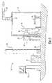
- FIG. 1is a generally schematic layout illustrating a kinetic spray system for performing the method of the present invention
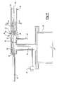
- FIG. 2is an enlarged cross-sectional view of one embodiment of a kinetic spray nozzle designed in accordance with the present invention and used in the system;
- FIG. 3is an exploded cross-sectional view of the supersonic portion of the nozzle
- FIG. 4is a cross-sectional view along line A-A of FIG. 2 ;
- FIG. 5is a cross-sectional view along line B-B of FIG. 3 ;
- FIG. 6is an enlarged cross-sectional view of another kinetic spray nozzle designed in accordance with the present invention and used in the system;
- FIG. 7is a cross-sectional view of another embodiment of a flow regulator designed in accordance with the present invention.
- FIG. 8is a cross-sectional view along line E-E of FIG. 6 ;
- FIG. 9is a cross-sectional view along line F-F of Figure.
- FIG. 10is a cross-sectional view of another embodiment of a tubular section designed in accordance with the present invention.
- System 10includes an enclosure 12 in which a support table 14 or other support means is located.
- a mounting panel 16 fixed to the table 14supports a work holder 18 capable of movement in three dimensions and able to support a suitable workpiece formed of a substrate material to be coated.
- the enclosure 12includes surrounding walls having at least one air inlet, not shown, and an air outlet 20 connected by a suitable exhaust conduit 22 to a dust collector, not shown.
- the dust collectorcontinually draws air from the enclosure 12 and collects any dust or particles contained in the exhaust air for subsequent disposal.
- the spray system 10further includes a gas compressor 24 capable of supplying gas pressure up to 3.4 MPa (500 psi) to a high pressure gas ballast tank 26 .
- the gas ballast tank 26is connected through a line 28 to both a high pressure powder feeder 30 and a separate gas heater 32 .
- the gas heater 32supplies high pressure heated gas, the main gas described below, to a kinetic spray nozzle 34 .
- the powder feeder 30mixes particles of a spray powder with unheated high pressure gas and supplies the mixture to a supplemental inlet line 48 of the nozzle 34 .
- a computer control 35operates to control both the pressure of gas supplied to the gas heater 32 and the temperature of the heated main gas exiting the gas heater 32 .
- the gascan comprise air, helium, nitrogen, neon, argon, or mixtures thereof.
- FIG. 2is a cross-sectional view of one embodiment of a nozzle 34 and its connections to the gas heater 32 and the supplemental inlet line 48 .
- a main gas passage 36connects the gas heater 32 to the nozzle 34 .
- Passage 36connects with a premix chamber 38 which directs the gas through a flow straightener 40 and into a mixing chamber 42 .
- Temperature and pressure of the heated main gasare monitored by a gas inlet temperature thermocouple 44 in the passage 36 and a pressure sensor 46 connected to the mixing chamber 42 .
- the mixture of unheated high pressure gas and coating powderis fed through the supplemental inlet line 48 to a powder injector tube 50 comprising a straight pipe having a predetermined inner diameter.
- the tube 50has a central axis 52 which is preferentially the same as the axis of the premix chamber 38 .
- the tube 50extends through the premix chamber 38 and the flow straightener 40 into the mixing chamber 42 . Particles 100 exit the tube 50 and are entrained in the main gas flow in the mixing chamber 42 .
- the nozzle 54has a tubular section 56 and a flow regulator 58 .
- the tubular section 56was an inner wall 60 with a diameter sufficiently large enough to receive a portion of the flow regulator 58 as is explained below.
- the tubular section 56is shown in FIG. 3 as having a cylindrical inner and outer shape, however, the inner and outer shapes could be any shape as will be recognized by one of ordinary skill in the art. It is important that the shape of the inner wall 60 allow for an annular flow gap 78 , as disclosed below.
- the flow regulator 58has a base portion 62 with a first half 64 opposite a second half 66 .
- a first cone 68projects from the first half 64 .
- a plurality of holes 70are spaced around the cone 68 and pass through the base portion 62 .
- a flow concentrator 72projects from the second half 66 .
- the flow concentrator 72is biconical with a second cone 74 and a third cone 76 , the second and third cones 74 , 76 sharing a common base diameter D.
- the diameter Dis less than a diameter of the inner wall 60 at the point where they are adjacent to each other, as shown in the Figures.
- the second half 66has a diameter that is less than a diameter of the first half 64 .
- the second half 66 and flow concentrator 72are received in the tubular section 56 with the diameter of the second half 66 matching that of a diameter of the inner wall 60 .
- the difference in the diameter D and the diameter of the inner wall 60 adjacent Ddefines an annular flow gap 78 .
- the flow gapis from 1 to 5 millimeters with from 2 to 3 especially preferred.
- the diameter of the inner wall 60is from 2 to 10 millimeters greater than D and more preferably from 4 to 6 millimeters greater than D at the point where they are adjacent to each other.
- the particles 100are entrained in the main gas flow in the mixing chamber 42 the first cone 68 directs the entrained particles 100 and main gas through the holes 70 into the tubular portion 56 .
- the second cone 74forces the flow of gas and particles 100 outward toward the inner wall 60 and the gap 78 . Once the flow and particles 100 reach the gap 78 the flow beyond the gap goes from sonic to supersonic.
- the shape of the third cone 76 and 60permit the main gas flow to force the particles 100 to follow the contour of cone 76 and concentrates the particles 100 into a well defined small spot.
- the main gaslargely flows outside the particle 100 stream and forces them into a compact flow. This enables one to create narrow width lines or spots in the absence of a mask. In fact, using the nozzle 54 of the present invention one can create spots having dimensions of 0.9 by 0.9 millimeters.
- the powder injector tube 50supplies a particle powder mixture to the system 10 under a pressure in excess of the pressure of the heated main gas from the passage 36 .
- the nozzle 54produces an exit velocity of the entrained particles 100 of from 200 meters per second to as high as 1200 meters per second.
- the entrained particles 100gain kinetic and thermal energy during their flow through this nozzle 54 .
- the temperature of the particles 100 in the gas streamwill vary depending on the size of the particles 100 and the main gas temperature.
- the main gas temperatureis defined as the temperature of heated high-pressure gas at the inlet to the nozzle 54 .
- the main gas temperaturesare set so that the particles 100 are only heated to a temperature that is less than the melting point of the particles 100 .
- This temperaturecan be substantially above the melting temperature of the particles 100 . Temperatures can range from 200 to 1000 degrees Celsius. Because the particles 100 are exposed to these elevated temperatures for such a short period of time the particles 100 never reach their melting temperature. Thus, even upon impact, there is no change in the solid phase of the original particles 100 due to transfer of kinetic and thermal energy, and therefore no change in their original physical properties.
- the particles 100are always at a temperature below the main gas temperature. The particles 100 exiting the nozzle 54 are directed toward a surface of a substrate to coat it.
- the particles 100Upon striking a substrate opposite the nozzle 54 the particles 100 flatten into a variety of nub-like structures with an aspect ratio of generally about 5 to 1.
- the substrateis a metal and the particles 100 are a metal the particles 100 striking the substrate surface fracture the oxidation on the surface layer and subsequently form a direct metal-to-metal bond between the metal particle 100 and the metal substrate.
- the kinetic sprayed particles 100transfer substantially all of their kinetic and thermal energy to the substrate surface and stick if their yield stress has been exceeded.
- critical velocityis defined as the velocity where at it will adhere to a substrate when it strikes the substrate after exiting the nozzle 54 .
- This critical velocityis dependent on the material composition of the particle 100 and the substrate. In general, harder materials must achieve a higher critical velocity before they adhere to a given substrate. It is not known at this time exactly what is the nature of the particle to substrate bond; however, it is believed that a portion of the bond is due to the particles 100 plastically deforming upon striking the substrate.
- the substrate materialmay be comprised of any of a wide variety of materials including a metal, an alloy, a semi-conductor, a ceramic, a plastic, and mixtures of these materials. All of these substrates can be coated by the process of the present invention.
- the particles used in the present inventionmay comprise any of the materials disclosed in U.S. Pat. Nos. 6,139,913 and 6,283,386 in addition to other know particles. These particles generally comprise metals, alloys, semiconductors, ceramics, polymers, diamonds and mixtures of these. In the present invention one can utilize particles 100 having a average nominal median diameter of from 1 to 200 microns, with 50 to 150 microns preferred and 50 to 125 microns especially preferred.
- a second embodiment of a supersonic nozzleis shown generally at 54 ′ in FIGS. 6-9 .
- the tubular section 56 ′is elongated compared to nozzle 54 .
- a powder injection tube 50 ′is elongated and extends through a flow regulator 58 ′ to the tip of third cone 76 .
- the elongated powder injector tube 50 ′is received inside a hole 120 in flow regulator 58 ′.
- the powderis injected at a pressure of from 100 to 150 psi using this nozzle 54 ′.
- the other parameters described above for the first embodiment, nozzle 54 , substrates, particles and main gasare equally useful for this embodiment.
- the other desirable modificationis to elongate the tubular section 56 ′ so it extends from 2.5 to 10 centimeters beyond the tip of third cone 76 .
- the particles 100are concentrated and focused by the main gas, which is supersonic after it passes through the gap 78 to produce a spot concentration of particles 100 .
- FIG. 10another embodiment of a tubular section 56 ′′ is shown.
- the tubular section 56 ′′includes a first portion 130 having a diameter sufficient to accommodate the flow regulator 58 , 58 ′ and to define the annular gap 78 between the first portion 130 and the flow regulator 58 , 58 ′ as described above.
- the tubular section 58 ′′further includes a second portion 132 that has a tapered shape.
- the tapered shapereceives the third cone 76 of the flow regulator 58 , 58 ′.
- This second portion 132ends in an exit end 134 .
- the exit end 134can have a variety of shapes including a rectangular shape, a circular shape, or a semi-circular shape.
- This tubular section 56 ′′can function to further concentrate the flow of particles 100 as they exit from the nozzle 54 , 54 ′.
- the present inventionpermits one to create discrete spots on substrates and very narrow width lines.
- the spotshave found use as electrical conductor points, wear points, and attachment points.
- the narrow width linescan be used to create electrical circuits and to coat very narrow width substrates.
Landscapes
- Chemical & Material Sciences (AREA)
- Chemical Kinetics & Catalysis (AREA)
- Engineering & Computer Science (AREA)
- Materials Engineering (AREA)
- Mechanical Engineering (AREA)
- Metallurgy (AREA)
- Organic Chemistry (AREA)
- Other Surface Treatments For Metallic Materials (AREA)
Abstract
Description
Claims (35)
Priority Applications (1)
| Application Number | Priority Date | Filing Date | Title |
|---|---|---|---|
| US10/808,246US7244466B2 (en) | 2004-03-24 | 2004-03-24 | Kinetic spray nozzle design for small spot coatings and narrow width structures |
Applications Claiming Priority (1)
| Application Number | Priority Date | Filing Date | Title |
|---|---|---|---|
| US10/808,246US7244466B2 (en) | 2004-03-24 | 2004-03-24 | Kinetic spray nozzle design for small spot coatings and narrow width structures |
Publications (2)
| Publication Number | Publication Date |
|---|---|
| US20050211799A1 US20050211799A1 (en) | 2005-09-29 |
| US7244466B2true US7244466B2 (en) | 2007-07-17 |
Family
ID=34988616
Family Applications (1)
| Application Number | Title | Priority Date | Filing Date |
|---|---|---|---|
| US10/808,246Expired - Fee RelatedUS7244466B2 (en) | 2004-03-24 | 2004-03-24 | Kinetic spray nozzle design for small spot coatings and narrow width structures |
Country Status (1)
| Country | Link |
|---|---|
| US (1) | US7244466B2 (en) |
Cited By (9)
| Publication number | Priority date | Publication date | Assignee | Title |
|---|---|---|---|---|
| US20070074656A1 (en)* | 2005-10-04 | 2007-04-05 | Zhibo Zhao | Non-clogging powder injector for a kinetic spray nozzle system |
| US20080271779A1 (en)* | 2007-05-04 | 2008-11-06 | H.C. Starck Inc. | Fine Grained, Non Banded, Refractory Metal Sputtering Targets with a Uniformly Random Crystallographic Orientation, Method for Making Such Film, and Thin Film Based Devices and Products Made Therefrom |
| US20100015467A1 (en)* | 2006-11-07 | 2010-01-21 | H.C. Starck Gmbh & Co., Kg | Method for coating a substrate and coated product |
| US20100055487A1 (en)* | 2005-05-05 | 2010-03-04 | H.C. Starck Gmbh | Method for coating a substrate surface and coated product |
| US20100061876A1 (en)* | 2008-09-09 | 2010-03-11 | H.C. Starck Inc. | Dynamic dehydriding of refractory metal powders |
| US20100272889A1 (en)* | 2006-10-03 | 2010-10-28 | H.C. Starch Inc. | Process for preparing metal powders having low oxygen content, powders so-produced and uses thereof |
| US20110197953A1 (en)* | 2008-10-13 | 2011-08-18 | Malibu Gmbh & Co. Kg | Method for connecting thin-film solar cells and thin-film solar module |
| US8113413B2 (en) | 2006-12-13 | 2012-02-14 | H.C. Starck, Inc. | Protective metal-clad structures |
| US8703233B2 (en) | 2011-09-29 | 2014-04-22 | H.C. Starck Inc. | Methods of manufacturing large-area sputtering targets by cold spray |
Families Citing this family (5)
| Publication number | Priority date | Publication date | Assignee | Title |
|---|---|---|---|---|
| US8758849B2 (en)* | 2007-08-06 | 2014-06-24 | Francis C. Dlubak | Method of depositing electrically conductive material onto a substrate |
| US10100412B2 (en)* | 2014-11-06 | 2018-10-16 | United Technologies Corporation | Cold spray nozzles |
| DE102015114202A1 (en)* | 2015-07-17 | 2017-01-19 | Sms Group Gmbh | Spray head for the cooling lubrication of at least one die of a forming machine and method for producing such a spray head |
| US20180156758A1 (en)* | 2016-12-05 | 2018-06-07 | Battelle Memorial Institute | Magnetostrictive cold spray coating for enhanced ultrasonic inspection |
| DE102017100438B4 (en) | 2017-01-11 | 2024-12-12 | Sms Group Gmbh | Two-component nozzle, spray head and method for atomizing a mixture of spray medium and spray air by means of a two-component nozzle |
Citations (2)
| Publication number | Priority date | Publication date | Assignee | Title |
|---|---|---|---|---|
| WO2003041868A2 (en)* | 2001-05-29 | 2003-05-22 | Linde Aktiengesellschaft | Cold gas spraying method and device |
| US20030190414A1 (en)* | 2002-04-05 | 2003-10-09 | Van Steenkiste Thomas Hubert | Low pressure powder injection method and system for a kinetic spray process |
- 2004
- 2004-03-24USUS10/808,246patent/US7244466B2/ennot_activeExpired - Fee Related
Patent Citations (3)
| Publication number | Priority date | Publication date | Assignee | Title |
|---|---|---|---|---|
| WO2003041868A2 (en)* | 2001-05-29 | 2003-05-22 | Linde Aktiengesellschaft | Cold gas spraying method and device |
| US20040166247A1 (en)* | 2001-05-29 | 2004-08-26 | Peter Heinrich | Method and system for cold gas spraying |
| US20030190414A1 (en)* | 2002-04-05 | 2003-10-09 | Van Steenkiste Thomas Hubert | Low pressure powder injection method and system for a kinetic spray process |
Cited By (27)
| Publication number | Priority date | Publication date | Assignee | Title |
|---|---|---|---|---|
| US20100055487A1 (en)* | 2005-05-05 | 2010-03-04 | H.C. Starck Gmbh | Method for coating a substrate surface and coated product |
| US8802191B2 (en) | 2005-05-05 | 2014-08-12 | H. C. Starck Gmbh | Method for coating a substrate surface and coated product |
| US20070074656A1 (en)* | 2005-10-04 | 2007-04-05 | Zhibo Zhao | Non-clogging powder injector for a kinetic spray nozzle system |
| US8715386B2 (en) | 2006-10-03 | 2014-05-06 | H.C. Starck Inc. | Process for preparing metal powders having low oxygen content, powders so-produced and uses thereof |
| US20100272889A1 (en)* | 2006-10-03 | 2010-10-28 | H.C. Starch Inc. | Process for preparing metal powders having low oxygen content, powders so-produced and uses thereof |
| US8226741B2 (en) | 2006-10-03 | 2012-07-24 | H.C. Starck, Inc. | Process for preparing metal powders having low oxygen content, powders so-produced and uses thereof |
| US20100015467A1 (en)* | 2006-11-07 | 2010-01-21 | H.C. Starck Gmbh & Co., Kg | Method for coating a substrate and coated product |
| US8448840B2 (en) | 2006-12-13 | 2013-05-28 | H.C. Starck Inc. | Methods of joining metallic protective layers |
| US8777090B2 (en) | 2006-12-13 | 2014-07-15 | H.C. Starck Inc. | Methods of joining metallic protective layers |
| US9095932B2 (en) | 2006-12-13 | 2015-08-04 | H.C. Starck Inc. | Methods of joining metallic protective layers |
| US8113413B2 (en) | 2006-12-13 | 2012-02-14 | H.C. Starck, Inc. | Protective metal-clad structures |
| US9783882B2 (en) | 2007-05-04 | 2017-10-10 | H.C. Starck Inc. | Fine grained, non banded, refractory metal sputtering targets with a uniformly random crystallographic orientation, method for making such film, and thin film based devices and products made therefrom |
| US8883250B2 (en) | 2007-05-04 | 2014-11-11 | H.C. Starck Inc. | Methods of rejuvenating sputtering targets |
| US8491959B2 (en) | 2007-05-04 | 2013-07-23 | H.C. Starck Inc. | Methods of rejuvenating sputtering targets |
| US8197894B2 (en) | 2007-05-04 | 2012-06-12 | H.C. Starck Gmbh | Methods of forming sputtering targets |
| US20080271779A1 (en)* | 2007-05-04 | 2008-11-06 | H.C. Starck Inc. | Fine Grained, Non Banded, Refractory Metal Sputtering Targets with a Uniformly Random Crystallographic Orientation, Method for Making Such Film, and Thin Film Based Devices and Products Made Therefrom |
| US8470396B2 (en) | 2008-09-09 | 2013-06-25 | H.C. Starck Inc. | Dynamic dehydriding of refractory metal powders |
| US8246903B2 (en) | 2008-09-09 | 2012-08-21 | H.C. Starck Inc. | Dynamic dehydriding of refractory metal powders |
| US8961867B2 (en) | 2008-09-09 | 2015-02-24 | H.C. Starck Inc. | Dynamic dehydriding of refractory metal powders |
| US20100061876A1 (en)* | 2008-09-09 | 2010-03-11 | H.C. Starck Inc. | Dynamic dehydriding of refractory metal powders |
| US20110197953A1 (en)* | 2008-10-13 | 2011-08-18 | Malibu Gmbh & Co. Kg | Method for connecting thin-film solar cells and thin-film solar module |
| US8734896B2 (en) | 2011-09-29 | 2014-05-27 | H.C. Starck Inc. | Methods of manufacturing high-strength large-area sputtering targets |
| US8703233B2 (en) | 2011-09-29 | 2014-04-22 | H.C. Starck Inc. | Methods of manufacturing large-area sputtering targets by cold spray |
| US9108273B2 (en) | 2011-09-29 | 2015-08-18 | H.C. Starck Inc. | Methods of manufacturing large-area sputtering targets using interlocking joints |
| US9120183B2 (en) | 2011-09-29 | 2015-09-01 | H.C. Starck Inc. | Methods of manufacturing large-area sputtering targets |
| US9293306B2 (en) | 2011-09-29 | 2016-03-22 | H.C. Starck, Inc. | Methods of manufacturing large-area sputtering targets using interlocking joints |
| US9412568B2 (en) | 2011-09-29 | 2016-08-09 | H.C. Starck, Inc. | Large-area sputtering targets |
Also Published As
| Publication number | Publication date |
|---|---|
| US20050211799A1 (en) | 2005-09-29 |
Similar Documents
| Publication | Publication Date | Title |
|---|---|---|
| US6623796B1 (en) | Method of producing a coating using a kinetic spray process with large particles and nozzles for the same | |
| US6811812B2 (en) | Low pressure powder injection method and system for a kinetic spray process | |
| US7108893B2 (en) | Spray system with combined kinetic spray and thermal spray ability | |
| US6743468B2 (en) | Method of coating with combined kinetic spray and thermal spray | |
| US6808817B2 (en) | Kinetically sprayed aluminum metal matrix composites for thermal management | |
| US7475831B2 (en) | Modified high efficiency kinetic spray nozzle | |
| US6569245B2 (en) | Method and apparatus for applying a powder coating | |
| EP1200200B2 (en) | Kinetic spray coating method and apparatus | |
| US7244466B2 (en) | Kinetic spray nozzle design for small spot coatings and narrow width structures | |
| US20060038044A1 (en) | Replaceable throat insert for a kinetic spray nozzle | |
| US20060251823A1 (en) | Kinetic spray application of coatings onto covered materials | |
| US20050214474A1 (en) | Kinetic spray nozzle system design | |
| EP1775026B1 (en) | Improved non-clogging powder injector for a kinetic spray nozzle system | |
| KR20090006119A (en) | Cold gas sprayer | |
| EP3105363B1 (en) | Plasma-kinetic spray apparatus&method | |
| US6872427B2 (en) | Method for producing electrical contacts using selective melting and a low pressure kinetic spray process | |
| EP1508379B1 (en) | Gas collimator for a kinetic powder spray nozzle | |
| US20040065432A1 (en) | High performance thermal stack for electrical components | |
| US7335341B2 (en) | Method for securing ceramic structures and forming electrical connections on the same | |
| US7351450B2 (en) | Correcting defective kinetically sprayed surfaces |
Legal Events
| Date | Code | Title | Description |
|---|---|---|---|
| AS | Assignment | Owner name:DELPHI TECHNOLOGIES, INC., MICHIGAN Free format text:ASSIGNMENT OF ASSIGNORS INTEREST;ASSIGNOR:VAN STEENKISTE, THOMAS HUBERT;REEL/FRAME:015537/0874 Effective date:20040415 | |
| AS | Assignment | Owner name:F.W. GARTNER THERMAL SPRAYING, LTD., TEXAS Free format text:ASSIGNMENT OF ASSIGNORS INTEREST;ASSIGNOR:DELPHI TECHNOLOGIES, INC.;REEL/FRAME:022793/0494 Effective date:20090422 Owner name:F.W. GARTNER THERMAL SPRAYING, LTD.,TEXAS Free format text:ASSIGNMENT OF ASSIGNORS INTEREST;ASSIGNOR:DELPHI TECHNOLOGIES, INC.;REEL/FRAME:022793/0494 Effective date:20090422 | |
| FEPP | Fee payment procedure | Free format text:PAT HOLDER CLAIMS SMALL ENTITY STATUS, ENTITY STATUS SET TO SMALL (ORIGINAL EVENT CODE: LTOS); ENTITY STATUS OF PATENT OWNER: SMALL ENTITY | |
| REMI | Maintenance fee reminder mailed | ||
| LAPS | Lapse for failure to pay maintenance fees | ||
| STCH | Information on status: patent discontinuation | Free format text:PATENT EXPIRED DUE TO NONPAYMENT OF MAINTENANCE FEES UNDER 37 CFR 1.362 | |
| FP | Lapsed due to failure to pay maintenance fee | Effective date:20110717 | |
| AS | Assignment | Owner name:FLAME-SPRAY INDUSTRIES, INC., NEW YORK Free format text:ASSIGNMENT OF ASSIGNORS INTEREST;ASSIGNOR:F.W. GARTNER THERMAL SPRAYING, LTD.;REEL/FRAME:027902/0906 Effective date:20120312 |