US7244266B2 - System for pain-reduced withdrawal of blood - Google Patents
System for pain-reduced withdrawal of bloodDownload PDFInfo
- Publication number
- US7244266B2 US7244266B2US10/360,015US36001503AUS7244266B2US 7244266 B2US7244266 B2US 7244266B2US 36001503 AUS36001503 AUS 36001503AUS 7244266 B2US7244266 B2US 7244266B2
- Authority
- US
- United States
- Prior art keywords
- lancet
- impulse
- tip
- contact surface
- exit opening
- Prior art date
- Legal status (The legal status is an assumption and is not a legal conclusion. Google has not performed a legal analysis and makes no representation as to the accuracy of the status listed.)
- Expired - Fee Related, expires
Links
- 239000008280bloodSubstances0.000titleclaimsabstractdescription54
- 210000004369bloodAnatomy0.000titleclaimsabstractdescription54
- 238000000034methodMethods0.000claimsabstractdescription11
- 230000001360synchronised effectEffects0.000claimsabstractdescription8
- 241001071861Lethrinus genivittatusSpecies0.000claims1
- 239000013521masticSubstances0.000claims1
- 230000001133accelerationEffects0.000description11
- 230000008058pain sensationEffects0.000description10
- 210000005036nerveAnatomy0.000description7
- 210000000929nociceptorAnatomy0.000description6
- 238000012360testing methodMethods0.000description6
- 230000001960triggered effectEffects0.000description6
- 238000010168coupling processMethods0.000description5
- 230000000694effectsEffects0.000description5
- 230000007246mechanismEffects0.000description5
- 108091008700nociceptorsProteins0.000description5
- 230000008878couplingEffects0.000description4
- 238000005859coupling reactionMethods0.000description4
- 210000000412mechanoreceptorAnatomy0.000description4
- 108091008704mechanoreceptorsProteins0.000description4
- 238000004458analytical methodMethods0.000description3
- 210000000746body regionAnatomy0.000description3
- 230000002349favourable effectEffects0.000description3
- 238000005259measurementMethods0.000description3
- 230000008569processEffects0.000description3
- 229910000831SteelInorganic materials0.000description2
- 210000001124body fluidAnatomy0.000description2
- 239000010839body fluidSubstances0.000description2
- 238000006243chemical reactionMethods0.000description2
- 238000011835investigationMethods0.000description2
- 238000004519manufacturing processMethods0.000description2
- 230000000873masking effectEffects0.000description2
- 108020003175receptorsProteins0.000description2
- 230000001105regulatory effectEffects0.000description2
- 230000000284resting effectEffects0.000description2
- 239000007787solidSubstances0.000description2
- 239000010959steelSubstances0.000description2
- 210000001519tissueAnatomy0.000description2
- 238000012546transferMethods0.000description2
- 230000003213activating effectEffects0.000description1
- 230000004913activationEffects0.000description1
- 210000001185bone marrowAnatomy0.000description1
- 210000004556brainAnatomy0.000description1
- 239000000919ceramicSubstances0.000description1
- 230000008859changeEffects0.000description1
- 238000010276constructionMethods0.000description1
- 238000011109contaminationMethods0.000description1
- 238000013016dampingMethods0.000description1
- 201000010099diseaseDiseases0.000description1
- 208000037265diseases, disorders, signs and symptomsDiseases0.000description1
- 238000002474experimental methodMethods0.000description1
- 238000001746injection mouldingMethods0.000description1
- 230000001788irregularEffects0.000description1
- 239000000463materialSubstances0.000description1
- 230000010534mechanism of actionEffects0.000description1
- 229910052751metalInorganic materials0.000description1
- 239000002184metalSubstances0.000description1
- 150000002739metalsChemical class0.000description1
- 238000012544monitoring processMethods0.000description1
- 230000035515penetrationEffects0.000description1
- 230000009467reductionEffects0.000description1
- 238000007789sealingMethods0.000description1
- 229910052710siliconInorganic materials0.000description1
- 239000010703siliconSubstances0.000description1
Images


Classifications
- A—HUMAN NECESSITIES
- A61—MEDICAL OR VETERINARY SCIENCE; HYGIENE
- A61B—DIAGNOSIS; SURGERY; IDENTIFICATION
- A61B5/00—Measuring for diagnostic purposes; Identification of persons
- A61B5/41—Detecting, measuring or recording for evaluating the immune or lymphatic systems
- A61B5/414—Evaluating particular organs or parts of the immune or lymphatic systems
- A61B5/417—Evaluating particular organs or parts of the immune or lymphatic systems the bone marrow
- A—HUMAN NECESSITIES
- A61—MEDICAL OR VETERINARY SCIENCE; HYGIENE
- A61B—DIAGNOSIS; SURGERY; IDENTIFICATION
- A61B5/00—Measuring for diagnostic purposes; Identification of persons
- A61B5/15—Devices for taking samples of blood
- A61B5/150007—Details
- A61B5/150015—Source of blood
- A61B5/150022—Source of blood for capillary blood or interstitial fluid
- A—HUMAN NECESSITIES
- A61—MEDICAL OR VETERINARY SCIENCE; HYGIENE
- A61B—DIAGNOSIS; SURGERY; IDENTIFICATION
- A61B5/00—Measuring for diagnostic purposes; Identification of persons
- A61B5/15—Devices for taking samples of blood
- A61B5/150007—Details
- A61B5/150053—Details for enhanced collection of blood or interstitial fluid at the sample site, e.g. by applying compression, heat, vibration, ultrasound, suction or vacuum to tissue; for reduction of pain or discomfort; Skin piercing elements, e.g. blades, needles, lancets or canulas, with adjustable piercing speed
- A61B5/150106—Means for reducing pain or discomfort applied before puncturing; desensitising the skin at the location where body is to be pierced
- A61B5/150137—Means for reducing pain or discomfort applied before puncturing; desensitising the skin at the location where body is to be pierced by vibration
- A—HUMAN NECESSITIES
- A61—MEDICAL OR VETERINARY SCIENCE; HYGIENE
- A61B—DIAGNOSIS; SURGERY; IDENTIFICATION
- A61B5/00—Measuring for diagnostic purposes; Identification of persons
- A61B5/15—Devices for taking samples of blood
- A61B5/150007—Details
- A61B5/150374—Details of piercing elements or protective means for preventing accidental injuries by such piercing elements
- A61B5/150381—Design of piercing elements
- A61B5/150412—Pointed piercing elements, e.g. needles, lancets for piercing the skin
- A—HUMAN NECESSITIES
- A61—MEDICAL OR VETERINARY SCIENCE; HYGIENE
- A61B—DIAGNOSIS; SURGERY; IDENTIFICATION
- A61B5/00—Measuring for diagnostic purposes; Identification of persons
- A61B5/15—Devices for taking samples of blood
- A61B5/150007—Details
- A61B5/150374—Details of piercing elements or protective means for preventing accidental injuries by such piercing elements
- A61B5/150381—Design of piercing elements
- A61B5/150503—Single-ended needles
- A—HUMAN NECESSITIES
- A61—MEDICAL OR VETERINARY SCIENCE; HYGIENE
- A61B—DIAGNOSIS; SURGERY; IDENTIFICATION
- A61B5/00—Measuring for diagnostic purposes; Identification of persons
- A61B5/15—Devices for taking samples of blood
- A61B5/151—Devices specially adapted for taking samples of capillary blood, e.g. by lancets, needles or blades
- A61B5/15101—Details
- A61B5/15103—Piercing procedure
- A61B5/15107—Piercing being assisted by a triggering mechanism
- A61B5/15113—Manually triggered, i.e. the triggering requires a deliberate action by the user such as pressing a drive button
- A—HUMAN NECESSITIES
- A61—MEDICAL OR VETERINARY SCIENCE; HYGIENE
- A61B—DIAGNOSIS; SURGERY; IDENTIFICATION
- A61B5/00—Measuring for diagnostic purposes; Identification of persons
- A61B5/15—Devices for taking samples of blood
- A61B5/151—Devices specially adapted for taking samples of capillary blood, e.g. by lancets, needles or blades
- A61B5/15101—Details
- A61B5/15115—Driving means for propelling the piercing element to pierce the skin, e.g. comprising mechanisms based on shape memory alloys, magnetism, solenoids, piezoelectric effect, biased elements, resilient elements, vacuum or compressed fluids
- A61B5/15117—Driving means for propelling the piercing element to pierce the skin, e.g. comprising mechanisms based on shape memory alloys, magnetism, solenoids, piezoelectric effect, biased elements, resilient elements, vacuum or compressed fluids comprising biased elements, resilient elements or a spring, e.g. a helical spring, leaf spring, or elastic strap
- A—HUMAN NECESSITIES
- A61—MEDICAL OR VETERINARY SCIENCE; HYGIENE
- A61B—DIAGNOSIS; SURGERY; IDENTIFICATION
- A61B5/00—Measuring for diagnostic purposes; Identification of persons
- A61B5/15—Devices for taking samples of blood
- A61B5/151—Devices specially adapted for taking samples of capillary blood, e.g. by lancets, needles or blades
- A61B5/15101—Details
- A61B5/15126—Means for controlling the lancing movement, e.g. 2D- or 3D-shaped elements, tooth-shaped elements or sliding guides
- A61B5/15128—Means for controlling the lancing movement, e.g. 2D- or 3D-shaped elements, tooth-shaped elements or sliding guides comprising 2D- or 3D-shaped elements, e.g. cams, curved guide rails or threads
- A—HUMAN NECESSITIES
- A61—MEDICAL OR VETERINARY SCIENCE; HYGIENE
- A61B—DIAGNOSIS; SURGERY; IDENTIFICATION
- A61B5/00—Measuring for diagnostic purposes; Identification of persons
- A61B5/15—Devices for taking samples of blood
- A61B5/151—Devices specially adapted for taking samples of capillary blood, e.g. by lancets, needles or blades
- A61B5/15186—Devices loaded with a single lancet, i.e. a single lancet with or without a casing is loaded into a reusable drive device and then discarded after use; drive devices reloadable for multiple use
- A61B5/15188—Constructional features of reusable driving devices
- A61B5/1519—Constructional features of reusable driving devices comprising driving means, e.g. a spring, for propelling the piercing unit
- A—HUMAN NECESSITIES
- A61—MEDICAL OR VETERINARY SCIENCE; HYGIENE
- A61B—DIAGNOSIS; SURGERY; IDENTIFICATION
- A61B5/00—Measuring for diagnostic purposes; Identification of persons
- A61B5/15—Devices for taking samples of blood
- A61B5/151—Devices specially adapted for taking samples of capillary blood, e.g. by lancets, needles or blades
- A61B5/15186—Devices loaded with a single lancet, i.e. a single lancet with or without a casing is loaded into a reusable drive device and then discarded after use; drive devices reloadable for multiple use
- A61B5/15188—Constructional features of reusable driving devices
- A61B5/15192—Constructional features of reusable driving devices comprising driving means, e.g. a spring, for retracting the lancet unit into the driving device housing
- A61B5/15194—Constructional features of reusable driving devices comprising driving means, e.g. a spring, for retracting the lancet unit into the driving device housing fully automatically retracted, i.e. the retraction does not require a deliberate action by the user, e.g. by terminating the contact with the patient's skin
- A—HUMAN NECESSITIES
- A61—MEDICAL OR VETERINARY SCIENCE; HYGIENE
- A61B—DIAGNOSIS; SURGERY; IDENTIFICATION
- A61B5/00—Measuring for diagnostic purposes; Identification of persons
- A61B5/15—Devices for taking samples of blood
- A61B5/150007—Details
- A61B5/150175—Adjustment of penetration depth
- A61B5/150198—Depth adjustment mechanism at the proximal end of the carrier of the piercing element
Definitions
- the present inventionconcerns a system for pain-reduced withdrawal of blood which comprises a lancet system which produces a small opening in the skin from which blood can emerge and an impulse generator which serves to reduce the pain sensation during blood withdrawal.
- Systems for blood withdrawalare mainly used by diabetics to monitor the blood sugar level.
- blood withdrawal devicesare also used in doctor's offices, hospitals etc. if only small amounts of blood in the range of a few ⁇ l or less are required for an examination or analytical test.
- blood withdrawal deviceshave become particularly important for diabetics due to the necessity for frequent testing. In this case blood has to be constantly collected and often several times daily in order to avoid blood sugar values which are either too high or too low and thus reduce secondary damage.
- a blood lancet deviceis described in WO 01/62150 which has hemispherical elevations on a cap that is pressed onto the skin for blood withdrawal which are intended to confuse the nerves which conduct the pain so that the puncture with the lancet is felt to be less painful by the user.
- a lancet deviceis disclosed in U.S. Pat. No. 6,306,152 in which a weight and a lancet arranged in a hole through the weight are both accelerated by a spring.
- the weight and lancetboth strike the body surface for blood withdrawal and the lancet moves further within the barrel due to its mass inertia so that it punctures the underlying tissue.
- the patent documentdescribes that the barrel stretches the skin which stabilizes the skin and thus makes the puncture less painful. This is achieved in that the barrel restricts the freedom of movement of the skin in the area of the lancing site.
- the described devicehas a number of significant disadvantages for its practical application. As shown in FIG. 5 of U.S. Pat. No.
- the maximum puncture depth of the lancetis determined by the length of a hole in the barrel in which the upper part of the needle moves. Since the puncture depth is predetermined by the length of the hole, it is not possible for the user to adjust the puncture depth in order to select a favourable puncture depth for his specific skin characteristics with which an adequate amount of blood can still be obtained for analysis with a minimum of pain.
- the movement of the lancet relative to the barrel by means of pure mass inertiacauses other serious problems.
- the available puncture depthmay not be completely utilized since the acceleration is insufficient for skin penetration. This is exacerbated by the fact that in the manufacturing process it is technically difficult to adequately control the friction between the lancet and the barrel.
- the lancetmay jam due to manufacturing variations or even if the lancet is slightly bent so that mass inertia is not even sufficient for skin puncture.
- Another disadvantageis that in order to replace the lancet, which should occur after every skin puncture for reasons of hygiene, it is necessary to dismantle the barrel and remove the lancet from it or to replace the entire unit of barrel and lancet.
- the object of the present inventionwas to propose a lancet device for blood withdrawal which minimizes the pain associated with withdrawal and enables a hygienic use.
- a lancet system for pain-reduced blood withdrawalwhich has a housing with a contact surface from which the tip of the lancet can emerge wherein the lancet located in a lancet holder is moved by means of a lancet drive and an impulse generator exerts an impulse on a part of the body which is synchronized with the lancing in order to reduce the pain sensation caused by the puncture.
- the inventionalso proposes a method for pain-reduced blood withdrawal in which an impulse is exerted on a part of the body that is synchronized with the puncturing of a body surface.
- the system and method according to the inventionresults in substantial improvements towards the goal of reducing the pain sensation associated with lancing.
- the puncture depthcan be controlled and, if necessary, also regulated by the movement of the lancet holder and thus also of the lancet along a predetermined lancing path. Furthermore synchronization of the impulse exerted on the skin relative to the time of the puncturing of the body optimizes the effect of masking the pain.
- the lancet systemcomprises a housing with a contact surface which a user of the system can position on a site on the body from which blood is to be withdrawn.
- the housingenables the user to handle the system and also protects the mechanism and the lancet from the environment.
- the contact surface which is pressed against the bodyhas an opening through which the tip of a lancet can emerge from the interior of the housing in order to penetrate into the skin.
- the opening in the contact surfacepreferably has a cross-section of less than 5 mm and preferably between 1 and 3 mm.
- the contact surface which is pressed against the body for blood withdrawalcan for example have the shape of a flat circular ring.
- the contact surfacemay also be deformable in order to facilitate the withdrawal of body fluid in such a manner that a lateral movement occurs when the contact surface is pressed against the body surface which has a milking effect.
- a contact surfaceis described in the International Application WO 01/89383 to which reference is herewith made.
- a lancetis understood within the scope of this invention as a device which comprises a needle with a tip which is suitable for producing an opening in the body.
- a needlecan for example be a solid needle as well as a hollow needle.
- Suitable materials for the needleare in particular metals and in particular high-quality steels and also blades made of flat steel, silicon, ceramics etc.
- Such a needlecan be easily held in a holder of the blood withdrawal system.
- the lancetadvantageously has a holding body in which the needle is located, in addition to the needle.
- Such holding bodiescan be manufactured from plastic which is injected around the needle in an injection moulding process. This holding body enables the lancet to be held in a holder of the system.
- the holding bodycan be designed such that it also encloses the tip region of the needle and thus protects it from contamination before use. Such a seal can be removed by unscrewing at a predetermined breaking point to expose the needle tip for blood collection. Since designs for holding a needle in a body and also for hygienically sealing the needle tip are well-known in the prior art, they are not described in more detail here.
- the blood withdrawal systemhas a movable lancet holder to hold the lancet which can be moved along a predetermined path in order to carry out a puncture for blood collection.
- the lancetcan for example be held in the lancet holder by pressure fitting or by wedging or locking.
- a particularly suitable lancet holder for the present inventionis described in EP 0 565 970.
- the lancet holderdoes not necessarily have to be a body which encloses the lancet in a holding area, but it can for example also be a type of spike which is mounted on the lancet.
- Suitable combinations of lancets and lancet holders which enable a form-fitting couplingare described in PCT/EP01/12527. Such coupling methods are particularly favourable within the scope of the present application since the form-fitting connection enables a guided forwards movement of the lancet for puncturing as well as when it is retracted into the housing which has proven to be less painful.
- the lancet holderis moved along a predetermined path by a lancet drive such that a lancet which is arranged in the lancet holder temporarily emerges from the exit opening and can pierce a body region which is located there.
- a lancet driveis known from the prior art.
- the springcan be designed such that it retracts the lancet from the lancing position and adopts a resting position in which the needle is located within the housing.
- a second springmay also be provided to retract the needle into the housing which drives the lancet back from the lancing position into the housing.
- Positively guided systemsmay also be used as a drive such as crankshaft drives, lever drives or cam controls in which the movement of the lancet is not left to the free play of spring and mass forces but can be exactly predetermined by the drive mechanism.
- a drive according to EP 0 565 970has proven to be particularly advantageous within the scope of the present invention in which the lancet holder is moved by a rotary slide gear.
- the lancet drivehas a sleeve with a groove in which a control pin moves which is connected to the lancet holder.
- the pinmoves within the groove and the movement of the lancet in the axial direction can be exactly predetermined within the tolerances by means of the shape of the groove.
- the guidance of the pin in the grooveenables an exact mechanical guidance of the lancet in a positive as well as in a negative lancing direction during the movement.
- This guidingwhich is referred to as positive drive coupling enables the generation of defined paths and times for the lancing movement which have proven to be particularly painless.
- a special feature of the blood withdrawal system according to the inventionis an impulse generator which exerts an impulse on a body part which is synchronized with the piercing of the lancet.
- Such an impulsestimulates mechanoreceptors in the tissue.
- These receptorsare connected to thick nerve fibres which have a high rate of conduction.
- pain receptorsnociceptors
- the bone marrowrepresents a gate where the fibres arrive from the periphery and are connected.
- the thin nerve fibres from the nociceptorsopen the gate so that pain sensation can reach the brain.
- the thick nerve fibres of the mechanoreceptorsclose the gate. The balance between the signals arriving from the thin and thick fibres determines the pain sensation.
- a mechanical impulse which is exerted in synchronization with the piercing of the lancetcan reduce or even completely suppress the pain sensation due to the needle puncture by exciting the mechanoreceptors. Since the signals of the mechanoreceptors are conducted more rapidly via the thick nerve fibres than the signals of the nociceptors, they are able to overtake the signals of the nociceptors even when the nociceptors are stimulated later and thus close the gate before the pain signal reaches it. Hence according to the invention the impulse can be exerted on the body region before the lancing as well as even shortly thereafter. Our investigations have shown that the impulse leads to a reduction of the perceived pain when it is triggered between 1000 and 0 milliseconds before the prick or between 0 and 100 milliseconds or preferably between 20 and 50 milliseconds after the prick.
- the impulse on the body regioncan be exerted by the impulse generator via the contact surface of the housing or by a separate ram.
- the impulse generator and lancet drivecan for example be constructed separately from one another and be controlled electrically by a control device.
- Blood withdrawal systemsare usually relatively small devices for example in the form of a pen which is held manually.
- the impulseis generated by a relative movement of masses of a limited size.
- the ratio of the masses and their relative speeddetermines the force exerted on the body part which stimulates the receptors. It has proven to be advantageous to provide a mass for generating the impulse in the interior of the housing which is moved relative to the housing. If this mass is accelerated away from the contact surface by a drive, the housing and the contact surface exerts an impulse on the body part.
- an impulse transferred to the body by means of a ramthere is also a relative movement of masses in which the housing moves away from the body part.
- the impulseshould preferably have a duration in the range of 0 to 10 or even better in the range of 1 to 7 milliseconds in order to achieve an efficient masking of the pain. This means that the impulse is not continuous but is cancelled again after a short time preferably by the blood withdrawal system itself by pulling the masses that have moved apart together again.
- the force which is exerted by the impulse generator on the body partis preferably in the range of 10 to 30 N.
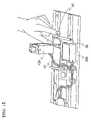
- FIG. 1Blood withdrawal system with a ram as an impulse generator.
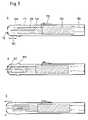
- FIG. 2Distance-time courses of the lancing and impulse using the system shown in FIG. 1 .
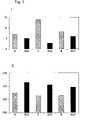
- FIG. 3Assessment of the pain sensation by test persons with the distance-time courses shown in FIG. 2 .
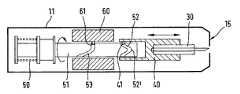
- FIG. 4Blood withdrawal system with a rotary slide gear.
- FIG. 5Blood withdrawal system with a spring-driven mass.
- FIG. 1shows a test construction for a blood withdrawal system with an impulse generator.
- the systemcomprises a conventional blood withdrawal system ( 10 ) as described in EP 0 565 970 which is commercially available under the name Softclix®.
- the blood withdrawal systemhas an activating button that can be triggered by an electromechanical actuator ( 100 ).
- a ram ( 20 )is located in the area of the contact surface that can be moved by a second electromechanical actuator ( 200 ) towards the body part.
- the first and second actuatorare connected by an electrical control unit (not shown) which activates the actuators in a synchronized sequence.
- Various sequences of lancing using the blood withdrawal system and a slap with the fork ( 20 )were examined with the arrangement shown in FIG. 1 .
- FIG. 2The time sequences are shown in FIG. 2 .
- the curves indicated by the dashed lineshow the distance travelled by the fork ( 20 ) versus time.
- the thin continuous lineshows the movement of the lancet over time.
- the thick horizontal linesindicate the time periods in which the actuators ( 100 , 200 ) are triggered.
- the first actuator ( 100 ) which triggers the blood lancethas crosses at its ends whereas the activation phase of the second actuator ( 200 ) for the fork is shown by rhombi.
- FIG. 2Ashows a situation in which an impact is triggered with the fork and the lancing is carried out while the fork is in the impact position.
- FIG. 2Bthe lancing was carried out while the fork begins its impact.
- FIG. 2Cshows a situation in which the lancing occurs first and the impact begins about 0.03 sec later.
- FIG. 3shows an investigation on the pain sensation associated with the various time sequences.
- the experimentswere carried out with 27 test persons and compared with corresponding blood withdrawals from the same test persons using a Softclix®.
- FIG. 3Ishows the number of blood withdrawals which were felt to be painless by the test persons.
- the dashed barscorrespond to the time sequences A, B, C shown in FIG. 2 .
- the black bars directly adjoining the right hand side of eachshow the number of blood withdrawals that were felt to be painless using a conventional Softclix®.
- the figureshows that the number of blood withdrawals that were felt to be painless can be increased by exerting the impulse.
- Cin which the impact occurred ca. 30 msec after the puncture is favourable with regard to pain sensation.
- FIG. 3 IIshows a ranking of the painfulness of the blood withdrawals with and without the slap.
- the hatched barsshow averaged pain rankings that were obtained for the corresponding time sequences A, B, C from FIG. 2 .
- the black bars to the rightshow reference measurements with the conventional Softclix®. This figure also shows that the pain sensation was considerably reduced on average by using the impulse.
- FIG. 4shows a path controlled system with a rotary slide gear which is based on the drive concept of EP 0 565 970.
- the systemhas a housing ( 11 ) for the manual handling and in which the drive mechanism is located.
- the drivecomprises an elastic drive element, in the present case a spring ( 50 ), one end of which is attached to the housing and the other end is connected to a gear member which in this case is a guide sleeve ( 51 ).
- the spring ( 50 )can be tensioned by turning the guide sleeve ( 51 ) such that it rotates in the direction shown in FIG. 4A when the spring relaxes.
- the sleeve ( 51 )has two grooves ( 52 , 53 ) of which the first ( 42 ) is used to drive the lancet holder ( 40 ).
- the sequence A, B, Cshows how the lancet holder and thus the lancet ( 30 ) which is attached therein is moved when the sleeve ( 51 ) rotates.
- the lancet holder ( 40 )has a pin ( 41 ) attached thereto which moves within the first groove ( 52 ). The lancet holder is secured against rotation such that it is pushed forwards by the pin when the sleeve rotates from position A to position B and reaches the extreme point ( 52 ′).
- the needle ( 30 ′) of the lancet ( 30 )emerges from the housing through an opening in the contact surface ( 15 ) and can puncture a body part that may be pressed against it.
- the pin ( 61 )which is connected to a cylindrical mass ( 60 ) as an impulse weight is moved through an essentially straight region in the second groove ( 53 ).
- the mass ( 60 )is only slightly accelerated.
- the lancet holderis moved back such that the lancet tip moves into the housing.
- the mass of the drive mechanism and of the housingare relatively small but the mass of the impulse weight should be as large as possible such that the inner force which accelerates the two masses relative to one another results in the largest possible acceleration of the instrument housing. If the impulse weight were small in comparison to the mass of the housing and drive, this relative acceleration would be small.
- FIG. 5shows a blood withdrawal system with an impulse generator which comprises a drive with two elastic drive elements.
- a unitcomprising a lancet holder ( 140 ) and a mass ( 160 ) attached thereto, the impulse mass, is located in the housing ( 111 ). This unit is tensioned against a drive spring ( 150 ) and locked with the lever ( 170 ).
- a lancet ( 130 ) with a needle ( 130 ′) for producing an opening in the skinis located within the lancet holder.
- the locking device ( 170 )is released, the unit of lancet holder and mass and thus also the lancet is accelerated by the drive spring ( 150 ) towards the cap ( 105 ) on which the contact surface ( 115 ) is located.
- FIG. 5Balso shows that a second spring, the return spring ( 152 ), is pressed together starting from its resting position in FIG. 5A by the unit of lancet holder and mass. The forwards movement of the lancet holder and its mass are brought to a standstill by this spring and additionally by a solid stop in the cap in a preferred embodiment. This braking process occurs over a relatively short path which results in an acceleration of a large magnitude.
- the housing ( 111 ) and cap ( 105 )are movably arranged axially to one another in that the cap ( 105 ) has a region with an enlarged inner cross-section ( 105 ′) in which the front part of the housing ( 111 ) is inserted.
- This movability of the captransfers the reaction force of the deceleration onto the cap which exerts an impact on a body part located at the contact surface.
- the capcan be rigidly connected to the instrument housing.
- the movability of the capenables the mass of the instrument housing to be used to capture the initial acceleration, but does not interfere with the transfer of the deceleration onto the cap by the moved mass and thus onto the body.
- the deceleration of the lancet holder and its impulse massshould be transferred to the surface to be pierced with as little damping as possible which requires a housing mass which is small relative to the impulse mass.
- the movability of the capthen decouples a (small) part from the remaining housing on which the deceleration of the impulse mass acts and in this manner the two opposing objectives (no lifting from the body surface, strongest possible impulse on the body surface) can be achieved in a single instrument.
- a mechanismis preferably used to tension the arrangement in which the cap is also returned to the initial position according to FIG. 5A when the lancet holder is retracted into the tensioned position according to FIG. 5A such that it again has the potential to move towards the contact surface when it is triggered.
- meanscan also be integrated to regulate the puncture depth.
- Thiscan for example be achieved by a two part cap ( 105 ) which has a first part which consists of a region with an enlarged inner cross-section ( 105 ′) and a thread.
- a second partconsists of the pressure surface ( 115 ) and also has a thread which fits the first thread.
- the two partsare now screwed onto one another and the puncture depth can be regulated by screwing the parts together.
Landscapes
- Health & Medical Sciences (AREA)
- Life Sciences & Earth Sciences (AREA)
- Heart & Thoracic Surgery (AREA)
- Surgery (AREA)
- Physics & Mathematics (AREA)
- Veterinary Medicine (AREA)
- Biophysics (AREA)
- Pathology (AREA)
- Engineering & Computer Science (AREA)
- Biomedical Technology (AREA)
- Public Health (AREA)
- Medical Informatics (AREA)
- Molecular Biology (AREA)
- Hematology (AREA)
- Animal Behavior & Ethology (AREA)
- General Health & Medical Sciences (AREA)
- Dermatology (AREA)
- Pain & Pain Management (AREA)
- Immunology (AREA)
- Vascular Medicine (AREA)
- Measurement Of The Respiration, Hearing Ability, Form, And Blood Characteristics Of Living Organisms (AREA)
- External Artificial Organs (AREA)
- Surgical Instruments (AREA)
Abstract
Description
Claims (19)
Applications Claiming Priority (2)
| Application Number | Priority Date | Filing Date | Title |
|---|---|---|---|
| DE10206254ADE10206254A1 (en) | 2002-02-15 | 2002-02-15 | System for taking pain-free blood |
| DE10206254.4 | 2002-02-15 |
Publications (2)
| Publication Number | Publication Date |
|---|---|
| US20030225429A1 US20030225429A1 (en) | 2003-12-04 |
| US7244266B2true US7244266B2 (en) | 2007-07-17 |
Family
ID=27618704
Family Applications (1)
| Application Number | Title | Priority Date | Filing Date |
|---|---|---|---|
| US10/360,015Expired - Fee RelatedUS7244266B2 (en) | 2002-02-15 | 2003-02-07 | System for pain-reduced withdrawal of blood |
Country Status (6)
| Country | Link |
|---|---|
| US (1) | US7244266B2 (en) |
| EP (1) | EP1336375B1 (en) |
| JP (1) | JP3643363B2 (en) |
| AT (1) | ATE466525T1 (en) |
| CA (1) | CA2418665C (en) |
| DE (2) | DE10206254A1 (en) |
Cited By (65)
| Publication number | Priority date | Publication date | Assignee | Title |
|---|---|---|---|---|
| US20060206135A1 (en)* | 2003-04-16 | 2006-09-14 | Arkray, Inc. | Puncture device |
| US20070055297A1 (en)* | 2003-05-21 | 2007-03-08 | Arkray, Inc. | Needle insertion device |
| US20070162063A1 (en)* | 2006-01-12 | 2007-07-12 | Owen Mumford, Ltd. | Lancet firing device |
| US20100004560A1 (en)* | 2001-10-22 | 2010-01-07 | Owen Mumford, Ltd. | Confuser crown skin pricker |
| US20100069845A1 (en)* | 2005-12-02 | 2010-03-18 | Owen Mumford, Ltd. | Injection method and apparatus |
| US7875047B2 (en) | 2002-04-19 | 2011-01-25 | Pelikan Technologies, Inc. | Method and apparatus for a multi-use body fluid sampling device with sterility barrier release |
| US7892183B2 (en) | 2002-04-19 | 2011-02-22 | Pelikan Technologies, Inc. | Method and apparatus for body fluid sampling and analyte sensing |
| US7901365B2 (en) | 2002-04-19 | 2011-03-08 | Pelikan Technologies, Inc. | Method and apparatus for penetrating tissue |
| US7909775B2 (en) | 2001-06-12 | 2011-03-22 | Pelikan Technologies, Inc. | Method and apparatus for lancet launching device integrated onto a blood-sampling cartridge |
| US7909777B2 (en) | 2002-04-19 | 2011-03-22 | Pelikan Technologies, Inc | Method and apparatus for penetrating tissue |
| US7909774B2 (en) | 2002-04-19 | 2011-03-22 | Pelikan Technologies, Inc. | Method and apparatus for penetrating tissue |
| US7909778B2 (en) | 2002-04-19 | 2011-03-22 | Pelikan Technologies, Inc. | Method and apparatus for penetrating tissue |
| US7914465B2 (en) | 2002-04-19 | 2011-03-29 | Pelikan Technologies, Inc. | Method and apparatus for penetrating tissue |
| US7976476B2 (en) | 2002-04-19 | 2011-07-12 | Pelikan Technologies, Inc. | Device and method for variable speed lancet |
| US7981055B2 (en) | 2001-06-12 | 2011-07-19 | Pelikan Technologies, Inc. | Tissue penetration device |
| US7981056B2 (en) | 2002-04-19 | 2011-07-19 | Pelikan Technologies, Inc. | Methods and apparatus for lancet actuation |
| US7988645B2 (en) | 2001-06-12 | 2011-08-02 | Pelikan Technologies, Inc. | Self optimizing lancing device with adaptation means to temporal variations in cutaneous properties |
| US8007446B2 (en) | 2002-04-19 | 2011-08-30 | Pelikan Technologies, Inc. | Method and apparatus for penetrating tissue |
| US8062231B2 (en) | 2002-04-19 | 2011-11-22 | Pelikan Technologies, Inc. | Method and apparatus for penetrating tissue |
| US8079960B2 (en) | 2002-04-19 | 2011-12-20 | Pelikan Technologies, Inc. | Methods and apparatus for lancet actuation |
| US8197421B2 (en) | 2002-04-19 | 2012-06-12 | Pelikan Technologies, Inc. | Method and apparatus for penetrating tissue |
| US8221334B2 (en) | 2002-04-19 | 2012-07-17 | Sanofi-Aventis Deutschland Gmbh | Method and apparatus for penetrating tissue |
| US8251921B2 (en) | 2003-06-06 | 2012-08-28 | Sanofi-Aventis Deutschland Gmbh | Method and apparatus for body fluid sampling and analyte sensing |
| US8262614B2 (en) | 2003-05-30 | 2012-09-11 | Pelikan Technologies, Inc. | Method and apparatus for fluid injection |
| US8267870B2 (en) | 2002-04-19 | 2012-09-18 | Sanofi-Aventis Deutschland Gmbh | Method and apparatus for body fluid sampling with hybrid actuation |
| US8282576B2 (en) | 2003-09-29 | 2012-10-09 | Sanofi-Aventis Deutschland Gmbh | Method and apparatus for an improved sample capture device |
| US8296918B2 (en) | 2003-12-31 | 2012-10-30 | Sanofi-Aventis Deutschland Gmbh | Method of manufacturing a fluid sampling device with improved analyte detecting member configuration |
| US8333710B2 (en) | 2002-04-19 | 2012-12-18 | Sanofi-Aventis Deutschland Gmbh | Tissue penetration device |
| US8360992B2 (en) | 2002-04-19 | 2013-01-29 | Sanofi-Aventis Deutschland Gmbh | Method and apparatus for penetrating tissue |
| US8372016B2 (en) | 2002-04-19 | 2013-02-12 | Sanofi-Aventis Deutschland Gmbh | Method and apparatus for body fluid sampling and analyte sensing |
| US8382682B2 (en) | 2002-04-19 | 2013-02-26 | Sanofi-Aventis Deutschland Gmbh | Method and apparatus for penetrating tissue |
| US20130072857A1 (en)* | 2007-06-29 | 2013-03-21 | Actuated Medical, Inc. | Medical tool for reduced penetration force with feedback means |
| US8435190B2 (en) | 2002-04-19 | 2013-05-07 | Sanofi-Aventis Deutschland Gmbh | Method and apparatus for penetrating tissue |
| US8439872B2 (en) | 1998-03-30 | 2013-05-14 | Sanofi-Aventis Deutschland Gmbh | Apparatus and method for penetration with shaft having a sensor for sensing penetration depth |
| US8469918B2 (en) | 2010-05-24 | 2013-06-25 | Steve FALLEK | Method and apparatus for performing injections while vibrating the skin |
| US8556829B2 (en) | 2002-04-19 | 2013-10-15 | Sanofi-Aventis Deutschland Gmbh | Method and apparatus for penetrating tissue |
| US8574895B2 (en) | 2002-12-30 | 2013-11-05 | Sanofi-Aventis Deutschland Gmbh | Method and apparatus using optical techniques to measure analyte levels |
| US8622952B2 (en) | 2009-03-27 | 2014-01-07 | Bing Innovations, Llc | System and method for pain reduction during skin puncture and breakable tip therefor |
| US8641644B2 (en) | 2000-11-21 | 2014-02-04 | Sanofi-Aventis Deutschland Gmbh | Blood testing apparatus having a rotatable cartridge with multiple lancing elements and testing means |
| US8652831B2 (en) | 2004-12-30 | 2014-02-18 | Sanofi-Aventis Deutschland Gmbh | Method and apparatus for analyte measurement test time |
| US8668664B2 (en) | 2004-09-20 | 2014-03-11 | Bing Innovations, Llc | Method for reducing pain during skin puncturing procedures |
| US8668656B2 (en) | 2003-12-31 | 2014-03-11 | Sanofi-Aventis Deutschland Gmbh | Method and apparatus for improving fluidic flow and sample capture |
| US8702624B2 (en) | 2006-09-29 | 2014-04-22 | Sanofi-Aventis Deutschland Gmbh | Analyte measurement device with a single shot actuator |
| US8721671B2 (en) | 2001-06-12 | 2014-05-13 | Sanofi-Aventis Deutschland Gmbh | Electric lancet actuator |
| US8784335B2 (en) | 2002-04-19 | 2014-07-22 | Sanofi-Aventis Deutschland Gmbh | Body fluid sampling device with a capacitive sensor |
| US8828203B2 (en) | 2004-05-20 | 2014-09-09 | Sanofi-Aventis Deutschland Gmbh | Printable hydrogels for biosensors |
| US8965476B2 (en) | 2010-04-16 | 2015-02-24 | Sanofi-Aventis Deutschland Gmbh | Tissue penetration device |
| US9125975B2 (en) | 2010-08-16 | 2015-09-08 | Becton, Dickinson And Company | User-actuated storage assembly for injection device |
| US9144401B2 (en) | 2003-06-11 | 2015-09-29 | Sanofi-Aventis Deutschland Gmbh | Low pain penetrating member |
| US9168340B2 (en) | 2009-03-27 | 2015-10-27 | Bing Innovations, Llc | System and method for pain reduction during skin puncture and breakable tip therefor |
| US9226699B2 (en) | 2002-04-19 | 2016-01-05 | Sanofi-Aventis Deutschland Gmbh | Body fluid sampling module with a continuous compression tissue interface surface |
| US9248267B2 (en) | 2002-04-19 | 2016-02-02 | Sanofi-Aventis Deustchland Gmbh | Tissue penetration device |
| US9314194B2 (en) | 2002-04-19 | 2016-04-19 | Sanofi-Aventis Deutschland Gmbh | Tissue penetration device |
| US9351680B2 (en) | 2003-10-14 | 2016-05-31 | Sanofi-Aventis Deutschland Gmbh | Method and apparatus for a variable user interface |
| US9375169B2 (en) | 2009-01-30 | 2016-06-28 | Sanofi-Aventis Deutschland Gmbh | Cam drive for managing disposable penetrating member actions with a single motor and motor and control system |
| US9386944B2 (en) | 2008-04-11 | 2016-07-12 | Sanofi-Aventis Deutschland Gmbh | Method and apparatus for analyte detecting device |
| US9427532B2 (en) | 2001-06-12 | 2016-08-30 | Sanofi-Aventis Deutschland Gmbh | Tissue penetration device |
| US9463287B1 (en) | 2004-09-20 | 2016-10-11 | Bing Innovations, Llc | Controlling usage of replaceable tool ends |
| US9539171B2 (en) | 2007-03-19 | 2017-01-10 | Bing Innovations, Llc | Apparatus for reducing pain during skin-puncturing procedures |
| US9775553B2 (en) | 2004-06-03 | 2017-10-03 | Sanofi-Aventis Deutschland Gmbh | Method and apparatus for a fluid sampling device |
| US9795747B2 (en) | 2010-06-02 | 2017-10-24 | Sanofi-Aventis Deutschland Gmbh | Methods and apparatus for lancet actuation |
| US9820684B2 (en) | 2004-06-03 | 2017-11-21 | Sanofi-Aventis Deutschland Gmbh | Method and apparatus for a fluid sampling device |
| US10092231B2 (en) | 2012-09-13 | 2018-10-09 | Facet Technologies, Llc | Push-to-charge mechanism for lancing device |
| US10695508B2 (en) | 2015-05-01 | 2020-06-30 | Bing Innovations, Llc | Reducing pain of skin piercing using vibration |
| US12102347B2 (en) | 2018-01-26 | 2024-10-01 | Bing Innovations, L.L.C. | Holder for mounting a handheld tool to a surface |
Families Citing this family (24)
| Publication number | Priority date | Publication date | Assignee | Title |
|---|---|---|---|---|
| US6036924A (en) | 1997-12-04 | 2000-03-14 | Hewlett-Packard Company | Cassette of lancet cartridges for sampling blood |
| JP4272051B2 (en) | 2001-06-12 | 2009-06-03 | ペリカン テクノロジーズ インコーポレイテッド | Blood sampling apparatus and method |
| WO2002101359A2 (en) | 2001-06-12 | 2002-12-19 | Pelikan Technologies, Inc. | Integrated blood sampling analysis system with multi-use sampling module |
| AU2002344825A1 (en) | 2001-06-12 | 2002-12-23 | Pelikan Technologies, Inc. | Method and apparatus for improving success rate of blood yield from a fingerstick |
| US7344894B2 (en) | 2001-10-16 | 2008-03-18 | Agilent Technologies, Inc. | Thermal regulation of fluidic samples within a diagnostic cartridge |
| WO2003088824A2 (en) | 2002-04-19 | 2003-10-30 | Pelikan Technologies, Inc. | Device and method for variable speed lancet |
| US7648468B2 (en) | 2002-04-19 | 2010-01-19 | Pelikon Technologies, Inc. | Method and apparatus for penetrating tissue |
| US7485128B2 (en) | 2002-04-19 | 2009-02-03 | Pelikan Technologies, Inc. | Method and apparatus for penetrating tissue |
| US7524293B2 (en) | 2002-04-19 | 2009-04-28 | Pelikan Technologies, Inc. | Method and apparatus for penetrating tissue |
| US7563232B2 (en) | 2002-04-19 | 2009-07-21 | Pelikan Technologies, Inc. | Method and apparatus for penetrating tissue |
| US7717863B2 (en) | 2002-04-19 | 2010-05-18 | Pelikan Technologies, Inc. | Method and apparatus for penetrating tissue |
| US7141058B2 (en) | 2002-04-19 | 2006-11-28 | Pelikan Technologies, Inc. | Method and apparatus for a body fluid sampling device using illumination |
| US7244265B2 (en) | 2002-04-19 | 2007-07-17 | Pelikan Technologies, Inc. | Method and apparatus for penetrating tissue |
| US7410468B2 (en) | 2002-04-19 | 2008-08-12 | Pelikan Technologies, Inc. | Method and apparatus for penetrating tissue |
| US7371247B2 (en) | 2002-04-19 | 2008-05-13 | Pelikan Technologies, Inc | Method and apparatus for penetrating tissue |
| US7291117B2 (en) | 2002-04-19 | 2007-11-06 | Pelikan Technologies, Inc. | Method and apparatus for penetrating tissue |
| US7374544B2 (en) | 2002-04-19 | 2008-05-20 | Pelikan Technologies, Inc. | Method and apparatus for penetrating tissue |
| EP1614382B1 (en)* | 2003-04-11 | 2012-07-11 | ARKRAY, Inc. | Needle insertion device |
| EP1635700B1 (en) | 2003-06-13 | 2016-03-09 | Sanofi-Aventis Deutschland GmbH | Apparatus for a point of care device |
| US20080119884A1 (en)* | 2004-09-09 | 2008-05-22 | Flora Bruce A | Single Puncture Lancing Fixture with Depth Adjustment and Control of Contact Force |
| US7704265B2 (en)* | 2005-11-03 | 2010-04-27 | Stat Medical Devices, Inc. | Disposable/single-use blade lancet device and method |
| US20070173876A1 (en)* | 2006-01-20 | 2007-07-26 | Lifescan, Inc. | Lancing device with dampened spring |
| WO2011131951A1 (en)* | 2010-04-23 | 2011-10-27 | Oliver Blackwell | Apparatus for effecting a vascular puncture in a patient |
| GB2498772A (en)* | 2012-01-27 | 2013-07-31 | Owen Mumford Ltd | Lancing device moving lancet needle in longitudinal and lateral directions, lancet needle and lancing device with anti-recocking means |
Citations (14)
| Publication number | Priority date | Publication date | Assignee | Title |
|---|---|---|---|---|
| US4014347A (en) | 1975-05-27 | 1977-03-29 | Staodynamics, Inc. | Transcutaneous nerve stimulator device and method |
| US5578014A (en) | 1992-04-29 | 1996-11-26 | Erez; Uri | Skin piercing devices for medical use |
| WO1997004157A1 (en) | 1995-07-21 | 1997-02-06 | Hisaka Works, Ltd. | Draft-type processing device and processing method |
| US5647851A (en) | 1995-06-12 | 1997-07-15 | Pokras; Norman M. | Method and apparatus for vibrating an injection device |
| WO1997042885A1 (en) | 1996-05-17 | 1997-11-20 | Mercury Diagnostics, Inc. | Methods and apparatus for sampling body fluid |
| JPH10508527A (en) | 1996-06-04 | 1998-08-25 | パルコ、ラボラトリーズ | Adjustable lancet tip |
| WO1999026539A1 (en) | 1997-11-21 | 1999-06-03 | Amira Medical | Body fluid sampling device |
| US6045567A (en) | 1999-02-23 | 2000-04-04 | Lifescan Inc. | Lancing device causing reduced pain |
| EP1074219A2 (en) | 1999-08-03 | 2001-02-07 | Becton Dickinson and Company | Lancer |
| US6210420B1 (en)* | 1999-01-19 | 2001-04-03 | Agilent Technologies, Inc. | Apparatus and method for efficient blood sampling with lancet |
| US6231531B1 (en) | 1999-04-09 | 2001-05-15 | Agilent Technologies, Inc. | Apparatus and method for minimizing pain perception |
| WO2001062150A1 (en) | 2000-02-22 | 2001-08-30 | Owen Mumford Limited | Improvements relating to skin prickers |
| US20010027328A1 (en) | 1999-03-08 | 2001-10-04 | Paul Lum | Multiple lancet device |
| US6306152B1 (en) | 1999-03-08 | 2001-10-23 | Agilent Technologies, Inc. | Lancet device with skin movement control and ballistic preload |
Family Cites Families (3)
| Publication number | Priority date | Publication date | Assignee | Title |
|---|---|---|---|---|
| DE4212315A1 (en) | 1992-04-13 | 1993-10-14 | Boehringer Mannheim Gmbh | Blood lancet device for drawing blood for diagnostic purposes |
| WO2001089393A1 (en) | 2000-05-19 | 2001-11-29 | C.R. Bard, Inc. | Tissue capturing and suturing device and method |
| DE10053974A1 (en) | 2000-10-31 | 2002-05-29 | Roche Diagnostics Gmbh | Blood collection system |
- 2002
- 2002-02-15DEDE10206254Apatent/DE10206254A1/ennot_activeWithdrawn
- 2003
- 2003-02-07USUS10/360,015patent/US7244266B2/ennot_activeExpired - Fee Related
- 2003-02-10JPJP2003032419Apatent/JP3643363B2/ennot_activeExpired - Fee Related
- 2003-02-11CACA2418665Apatent/CA2418665C/ennot_activeExpired - Fee Related
- 2003-02-12DEDE50312679Tpatent/DE50312679D1/ennot_activeExpired - Lifetime
- 2003-02-12EPEP03003032Apatent/EP1336375B1/ennot_activeExpired - Lifetime
- 2003-02-12ATAT03003032Tpatent/ATE466525T1/enactive
Patent Citations (18)
| Publication number | Priority date | Publication date | Assignee | Title |
|---|---|---|---|---|
| US4014347A (en) | 1975-05-27 | 1977-03-29 | Staodynamics, Inc. | Transcutaneous nerve stimulator device and method |
| US5921963A (en) | 1992-04-29 | 1999-07-13 | Mali-Tech Ltd. | Skin piercing devices for medical use |
| US5578014A (en) | 1992-04-29 | 1996-11-26 | Erez; Uri | Skin piercing devices for medical use |
| US5647851A (en) | 1995-06-12 | 1997-07-15 | Pokras; Norman M. | Method and apparatus for vibrating an injection device |
| WO1997004157A1 (en) | 1995-07-21 | 1997-02-06 | Hisaka Works, Ltd. | Draft-type processing device and processing method |
| WO1997042885A1 (en) | 1996-05-17 | 1997-11-20 | Mercury Diagnostics, Inc. | Methods and apparatus for sampling body fluid |
| JPH10508527A (en) | 1996-06-04 | 1998-08-25 | パルコ、ラボラトリーズ | Adjustable lancet tip |
| WO1999026539A1 (en) | 1997-11-21 | 1999-06-03 | Amira Medical | Body fluid sampling device |
| JPH11164825A (en) | 1997-11-21 | 1999-06-22 | Mercury Diagnostics Inc | Sampling device of humor |
| US6210420B1 (en)* | 1999-01-19 | 2001-04-03 | Agilent Technologies, Inc. | Apparatus and method for efficient blood sampling with lancet |
| US6045567A (en) | 1999-02-23 | 2000-04-04 | Lifescan Inc. | Lancing device causing reduced pain |
| JP2000237172A (en) | 1999-02-23 | 2000-09-05 | Lifescan Inc | Piercing device reducing pain |
| US20010027328A1 (en) | 1999-03-08 | 2001-10-04 | Paul Lum | Multiple lancet device |
| US6306152B1 (en) | 1999-03-08 | 2001-10-23 | Agilent Technologies, Inc. | Lancet device with skin movement control and ballistic preload |
| US6231531B1 (en) | 1999-04-09 | 2001-05-15 | Agilent Technologies, Inc. | Apparatus and method for minimizing pain perception |
| EP1074219A2 (en) | 1999-08-03 | 2001-02-07 | Becton Dickinson and Company | Lancer |
| JP2001087251A (en) | 1999-08-03 | 2001-04-03 | Becton Dickinson & Co | Lancer |
| WO2001062150A1 (en) | 2000-02-22 | 2001-08-30 | Owen Mumford Limited | Improvements relating to skin prickers |
Non-Patent Citations (4)
| Title |
|---|
| Melzack et al., "Pain Mechanisms: A New Theory," Science, vol. 150, No. 3699 (1965), pp. 971-979. |
| Wall et al., "Masking and Metacontrast Phenomena in the Skin Sensory System," Experimental Neurology 8, 35-46 (1963). |
| Wall, "The Gate Control Theory of Pain Mechanisms," Brain (1978), 101, 1-18. |
| Webster et al, "Use of Transcutaneous Electrical Nerve Stimulation for Fingertip Analgesia: A Pilot Study," Annals of Emergency Medicine, Jun. 29, 1992. |
Cited By (133)
| Publication number | Priority date | Publication date | Assignee | Title |
|---|---|---|---|---|
| US8439872B2 (en) | 1998-03-30 | 2013-05-14 | Sanofi-Aventis Deutschland Gmbh | Apparatus and method for penetration with shaft having a sensor for sensing penetration depth |
| US8641644B2 (en) | 2000-11-21 | 2014-02-04 | Sanofi-Aventis Deutschland Gmbh | Blood testing apparatus having a rotatable cartridge with multiple lancing elements and testing means |
| US8845550B2 (en) | 2001-06-12 | 2014-09-30 | Sanofi-Aventis Deutschland Gmbh | Tissue penetration device |
| US8123700B2 (en) | 2001-06-12 | 2012-02-28 | Pelikan Technologies, Inc. | Method and apparatus for lancet launching device integrated onto a blood-sampling cartridge |
| US9694144B2 (en) | 2001-06-12 | 2017-07-04 | Sanofi-Aventis Deutschland Gmbh | Sampling module device and method |
| US8206319B2 (en) | 2001-06-12 | 2012-06-26 | Sanofi-Aventis Deutschland Gmbh | Tissue penetration device |
| US9427532B2 (en) | 2001-06-12 | 2016-08-30 | Sanofi-Aventis Deutschland Gmbh | Tissue penetration device |
| US8206317B2 (en) | 2001-06-12 | 2012-06-26 | Sanofi-Aventis Deutschland Gmbh | Tissue penetration device |
| US7909775B2 (en) | 2001-06-12 | 2011-03-22 | Pelikan Technologies, Inc. | Method and apparatus for lancet launching device integrated onto a blood-sampling cartridge |
| US8721671B2 (en) | 2001-06-12 | 2014-05-13 | Sanofi-Aventis Deutschland Gmbh | Electric lancet actuator |
| US8679033B2 (en) | 2001-06-12 | 2014-03-25 | Sanofi-Aventis Deutschland Gmbh | Tissue penetration device |
| US8641643B2 (en) | 2001-06-12 | 2014-02-04 | Sanofi-Aventis Deutschland Gmbh | Sampling module device and method |
| US9802007B2 (en) | 2001-06-12 | 2017-10-31 | Sanofi-Aventis Deutschland Gmbh | Methods and apparatus for lancet actuation |
| US8622930B2 (en) | 2001-06-12 | 2014-01-07 | Sanofi-Aventis Deutschland Gmbh | Tissue penetration device |
| US8162853B2 (en) | 2001-06-12 | 2012-04-24 | Pelikan Technologies, Inc. | Tissue penetration device |
| US9937298B2 (en) | 2001-06-12 | 2018-04-10 | Sanofi-Aventis Deutschland Gmbh | Tissue penetration device |
| US8337421B2 (en) | 2001-06-12 | 2012-12-25 | Sanofi-Aventis Deutschland Gmbh | Tissue penetration device |
| US8360991B2 (en) | 2001-06-12 | 2013-01-29 | Sanofi-Aventis Deutschland Gmbh | Tissue penetration device |
| US7988645B2 (en) | 2001-06-12 | 2011-08-02 | Pelikan Technologies, Inc. | Self optimizing lancing device with adaptation means to temporal variations in cutaneous properties |
| US8343075B2 (en) | 2001-06-12 | 2013-01-01 | Sanofi-Aventis Deutschland Gmbh | Tissue penetration device |
| US7981055B2 (en) | 2001-06-12 | 2011-07-19 | Pelikan Technologies, Inc. | Tissue penetration device |
| US8016774B2 (en) | 2001-06-12 | 2011-09-13 | Pelikan Technologies, Inc. | Tissue penetration device |
| US8282577B2 (en) | 2001-06-12 | 2012-10-09 | Sanofi-Aventis Deutschland Gmbh | Method and apparatus for lancet launching device integrated onto a blood-sampling cartridge |
| US8216154B2 (en) | 2001-06-12 | 2012-07-10 | Sanofi-Aventis Deutschland Gmbh | Tissue penetration device |
| US8382683B2 (en) | 2001-06-12 | 2013-02-26 | Sanofi-Aventis Deutschland Gmbh | Tissue penetration device |
| US8211037B2 (en) | 2001-06-12 | 2012-07-03 | Pelikan Technologies, Inc. | Tissue penetration device |
| US20100004560A1 (en)* | 2001-10-22 | 2010-01-07 | Owen Mumford, Ltd. | Confuser crown skin pricker |
| US9560993B2 (en) | 2001-11-21 | 2017-02-07 | Sanofi-Aventis Deutschland Gmbh | Blood testing apparatus having a rotatable cartridge with multiple lancing elements and testing means |
| US8556829B2 (en) | 2002-04-19 | 2013-10-15 | Sanofi-Aventis Deutschland Gmbh | Method and apparatus for penetrating tissue |
| US8690796B2 (en) | 2002-04-19 | 2014-04-08 | Sanofi-Aventis Deutschland Gmbh | Method and apparatus for penetrating tissue |
| US8202231B2 (en) | 2002-04-19 | 2012-06-19 | Sanofi-Aventis Deutschland Gmbh | Method and apparatus for penetrating tissue |
| US8197421B2 (en) | 2002-04-19 | 2012-06-12 | Pelikan Technologies, Inc. | Method and apparatus for penetrating tissue |
| US9907502B2 (en) | 2002-04-19 | 2018-03-06 | Sanofi-Aventis Deutschland Gmbh | Method and apparatus for penetrating tissue |
| US8157748B2 (en) | 2002-04-19 | 2012-04-17 | Pelikan Technologies, Inc. | Methods and apparatus for lancet actuation |
| US8079960B2 (en) | 2002-04-19 | 2011-12-20 | Pelikan Technologies, Inc. | Methods and apparatus for lancet actuation |
| US8221334B2 (en) | 2002-04-19 | 2012-07-17 | Sanofi-Aventis Deutschland Gmbh | Method and apparatus for penetrating tissue |
| US8235915B2 (en) | 2002-04-19 | 2012-08-07 | Sanofi-Aventis Deutschland Gmbh | Method and apparatus for penetrating tissue |
| US9839386B2 (en) | 2002-04-19 | 2017-12-12 | Sanofi-Aventis Deustschland Gmbh | Body fluid sampling device with capacitive sensor |
| US9795334B2 (en) | 2002-04-19 | 2017-10-24 | Sanofi-Aventis Deutschland Gmbh | Method and apparatus for penetrating tissue |
| US8267870B2 (en) | 2002-04-19 | 2012-09-18 | Sanofi-Aventis Deutschland Gmbh | Method and apparatus for body fluid sampling with hybrid actuation |
| US9724021B2 (en) | 2002-04-19 | 2017-08-08 | Sanofi-Aventis Deutschland Gmbh | Method and apparatus for penetrating tissue |
| US8062231B2 (en) | 2002-04-19 | 2011-11-22 | Pelikan Technologies, Inc. | Method and apparatus for penetrating tissue |
| US7875047B2 (en) | 2002-04-19 | 2011-01-25 | Pelikan Technologies, Inc. | Method and apparatus for a multi-use body fluid sampling device with sterility barrier release |
| US8333710B2 (en) | 2002-04-19 | 2012-12-18 | Sanofi-Aventis Deutschland Gmbh | Tissue penetration device |
| US8007446B2 (en) | 2002-04-19 | 2011-08-30 | Pelikan Technologies, Inc. | Method and apparatus for penetrating tissue |
| US8337419B2 (en) | 2002-04-19 | 2012-12-25 | Sanofi-Aventis Deutschland Gmbh | Tissue penetration device |
| US8337420B2 (en) | 2002-04-19 | 2012-12-25 | Sanofi-Aventis Deutschland Gmbh | Tissue penetration device |
| US7988644B2 (en) | 2002-04-19 | 2011-08-02 | Pelikan Technologies, Inc. | Method and apparatus for a multi-use body fluid sampling device with sterility barrier release |
| US8360992B2 (en) | 2002-04-19 | 2013-01-29 | Sanofi-Aventis Deutschland Gmbh | Method and apparatus for penetrating tissue |
| US7981056B2 (en) | 2002-04-19 | 2011-07-19 | Pelikan Technologies, Inc. | Methods and apparatus for lancet actuation |
| US8366637B2 (en) | 2002-04-19 | 2013-02-05 | Sanofi-Aventis Deutschland Gmbh | Method and apparatus for penetrating tissue |
| US8372016B2 (en) | 2002-04-19 | 2013-02-12 | Sanofi-Aventis Deutschland Gmbh | Method and apparatus for body fluid sampling and analyte sensing |
| US9498160B2 (en) | 2002-04-19 | 2016-11-22 | Sanofi-Aventis Deutschland Gmbh | Method for penetrating tissue |
| US8382682B2 (en) | 2002-04-19 | 2013-02-26 | Sanofi-Aventis Deutschland Gmbh | Method and apparatus for penetrating tissue |
| US7976476B2 (en) | 2002-04-19 | 2011-07-12 | Pelikan Technologies, Inc. | Device and method for variable speed lancet |
| US8388551B2 (en) | 2002-04-19 | 2013-03-05 | Sanofi-Aventis Deutschland Gmbh | Method and apparatus for multi-use body fluid sampling device with sterility barrier release |
| US7892183B2 (en) | 2002-04-19 | 2011-02-22 | Pelikan Technologies, Inc. | Method and apparatus for body fluid sampling and analyte sensing |
| US9339612B2 (en) | 2002-04-19 | 2016-05-17 | Sanofi-Aventis Deutschland Gmbh | Tissue penetration device |
| US8403864B2 (en) | 2002-04-19 | 2013-03-26 | Sanofi-Aventis Deutschland Gmbh | Method and apparatus for penetrating tissue |
| US8414503B2 (en) | 2002-04-19 | 2013-04-09 | Sanofi-Aventis Deutschland Gmbh | Methods and apparatus for lancet actuation |
| US8430828B2 (en) | 2002-04-19 | 2013-04-30 | Sanofi-Aventis Deutschland Gmbh | Method and apparatus for a multi-use body fluid sampling device with sterility barrier release |
| US8435190B2 (en) | 2002-04-19 | 2013-05-07 | Sanofi-Aventis Deutschland Gmbh | Method and apparatus for penetrating tissue |
| US7959582B2 (en) | 2002-04-19 | 2011-06-14 | Pelikan Technologies, Inc. | Method and apparatus for penetrating tissue |
| US9314194B2 (en) | 2002-04-19 | 2016-04-19 | Sanofi-Aventis Deutschland Gmbh | Tissue penetration device |
| US8491500B2 (en) | 2002-04-19 | 2013-07-23 | Sanofi-Aventis Deutschland Gmbh | Methods and apparatus for lancet actuation |
| US8496601B2 (en) | 2002-04-19 | 2013-07-30 | Sanofi-Aventis Deutschland Gmbh | Methods and apparatus for lancet actuation |
| US9248267B2 (en) | 2002-04-19 | 2016-02-02 | Sanofi-Aventis Deustchland Gmbh | Tissue penetration device |
| US9226699B2 (en) | 2002-04-19 | 2016-01-05 | Sanofi-Aventis Deutschland Gmbh | Body fluid sampling module with a continuous compression tissue interface surface |
| US8562545B2 (en) | 2002-04-19 | 2013-10-22 | Sanofi-Aventis Deutschland Gmbh | Tissue penetration device |
| US9186468B2 (en) | 2002-04-19 | 2015-11-17 | Sanofi-Aventis Deutschland Gmbh | Method and apparatus for penetrating tissue |
| US8574168B2 (en) | 2002-04-19 | 2013-11-05 | Sanofi-Aventis Deutschland Gmbh | Method and apparatus for a multi-use body fluid sampling device with analyte sensing |
| US8579831B2 (en) | 2002-04-19 | 2013-11-12 | Sanofi-Aventis Deutschland Gmbh | Method and apparatus for penetrating tissue |
| US7938787B2 (en) | 2002-04-19 | 2011-05-10 | Pelikan Technologies, Inc. | Method and apparatus for penetrating tissue |
| US9089678B2 (en) | 2002-04-19 | 2015-07-28 | Sanofi-Aventis Deutschland Gmbh | Method and apparatus for penetrating tissue |
| US8636673B2 (en) | 2002-04-19 | 2014-01-28 | Sanofi-Aventis Deutschland Gmbh | Tissue penetration device |
| US7914465B2 (en) | 2002-04-19 | 2011-03-29 | Pelikan Technologies, Inc. | Method and apparatus for penetrating tissue |
| US7909778B2 (en) | 2002-04-19 | 2011-03-22 | Pelikan Technologies, Inc. | Method and apparatus for penetrating tissue |
| US9089294B2 (en) | 2002-04-19 | 2015-07-28 | Sanofi-Aventis Deutschland Gmbh | Analyte measurement device with a single shot actuator |
| US9072842B2 (en) | 2002-04-19 | 2015-07-07 | Sanofi-Aventis Deutschland Gmbh | Method and apparatus for penetrating tissue |
| US8905945B2 (en) | 2002-04-19 | 2014-12-09 | Dominique M. Freeman | Method and apparatus for penetrating tissue |
| US7909774B2 (en) | 2002-04-19 | 2011-03-22 | Pelikan Technologies, Inc. | Method and apparatus for penetrating tissue |
| US8197423B2 (en) | 2002-04-19 | 2012-06-12 | Pelikan Technologies, Inc. | Method and apparatus for penetrating tissue |
| US7901365B2 (en) | 2002-04-19 | 2011-03-08 | Pelikan Technologies, Inc. | Method and apparatus for penetrating tissue |
| US7909777B2 (en) | 2002-04-19 | 2011-03-22 | Pelikan Technologies, Inc | Method and apparatus for penetrating tissue |
| US8845549B2 (en) | 2002-04-19 | 2014-09-30 | Sanofi-Aventis Deutschland Gmbh | Method for penetrating tissue |
| US8784335B2 (en) | 2002-04-19 | 2014-07-22 | Sanofi-Aventis Deutschland Gmbh | Body fluid sampling device with a capacitive sensor |
| US8808201B2 (en) | 2002-04-19 | 2014-08-19 | Sanofi-Aventis Deutschland Gmbh | Methods and apparatus for penetrating tissue |
| US9034639B2 (en) | 2002-12-30 | 2015-05-19 | Sanofi-Aventis Deutschland Gmbh | Method and apparatus using optical techniques to measure analyte levels |
| US8574895B2 (en) | 2002-12-30 | 2013-11-05 | Sanofi-Aventis Deutschland Gmbh | Method and apparatus using optical techniques to measure analyte levels |
| US20060206135A1 (en)* | 2003-04-16 | 2006-09-14 | Arkray, Inc. | Puncture device |
| US8187295B2 (en)* | 2003-04-16 | 2012-05-29 | Arkray, Inc. | Puncture device |
| US20070055297A1 (en)* | 2003-05-21 | 2007-03-08 | Arkray, Inc. | Needle insertion device |
| US8506586B2 (en)* | 2003-05-21 | 2013-08-13 | Arkray, Inc. | Needle insertion device |
| US8262614B2 (en) | 2003-05-30 | 2012-09-11 | Pelikan Technologies, Inc. | Method and apparatus for fluid injection |
| US8251921B2 (en) | 2003-06-06 | 2012-08-28 | Sanofi-Aventis Deutschland Gmbh | Method and apparatus for body fluid sampling and analyte sensing |
| US10034628B2 (en) | 2003-06-11 | 2018-07-31 | Sanofi-Aventis Deutschland Gmbh | Low pain penetrating member |
| US9144401B2 (en) | 2003-06-11 | 2015-09-29 | Sanofi-Aventis Deutschland Gmbh | Low pain penetrating member |
| US8945910B2 (en) | 2003-09-29 | 2015-02-03 | Sanofi-Aventis Deutschland Gmbh | Method and apparatus for an improved sample capture device |
| US8282576B2 (en) | 2003-09-29 | 2012-10-09 | Sanofi-Aventis Deutschland Gmbh | Method and apparatus for an improved sample capture device |
| US9351680B2 (en) | 2003-10-14 | 2016-05-31 | Sanofi-Aventis Deutschland Gmbh | Method and apparatus for a variable user interface |
| US9561000B2 (en) | 2003-12-31 | 2017-02-07 | Sanofi-Aventis Deutschland Gmbh | Method and apparatus for improving fluidic flow and sample capture |
| US8296918B2 (en) | 2003-12-31 | 2012-10-30 | Sanofi-Aventis Deutschland Gmbh | Method of manufacturing a fluid sampling device with improved analyte detecting member configuration |
| US8668656B2 (en) | 2003-12-31 | 2014-03-11 | Sanofi-Aventis Deutschland Gmbh | Method and apparatus for improving fluidic flow and sample capture |
| US8828203B2 (en) | 2004-05-20 | 2014-09-09 | Sanofi-Aventis Deutschland Gmbh | Printable hydrogels for biosensors |
| US9261476B2 (en) | 2004-05-20 | 2016-02-16 | Sanofi Sa | Printable hydrogel for biosensors |
| US9820684B2 (en) | 2004-06-03 | 2017-11-21 | Sanofi-Aventis Deutschland Gmbh | Method and apparatus for a fluid sampling device |
| US9775553B2 (en) | 2004-06-03 | 2017-10-03 | Sanofi-Aventis Deutschland Gmbh | Method and apparatus for a fluid sampling device |
| US9463287B1 (en) | 2004-09-20 | 2016-10-11 | Bing Innovations, Llc | Controlling usage of replaceable tool ends |
| US9675766B2 (en) | 2004-09-20 | 2017-06-13 | Bing Innovations, Llc | Method for pain-reducing skin puncture |
| US8668664B2 (en) | 2004-09-20 | 2014-03-11 | Bing Innovations, Llc | Method for reducing pain during skin puncturing procedures |
| US8652831B2 (en) | 2004-12-30 | 2014-02-18 | Sanofi-Aventis Deutschland Gmbh | Method and apparatus for analyte measurement test time |
| US8905971B2 (en) | 2005-12-02 | 2014-12-09 | Owen Mumford, Ltd. | Injection method and apparatus |
| US20100069845A1 (en)* | 2005-12-02 | 2010-03-18 | Owen Mumford, Ltd. | Injection method and apparatus |
| US20070162063A1 (en)* | 2006-01-12 | 2007-07-12 | Owen Mumford, Ltd. | Lancet firing device |
| US8372103B2 (en)* | 2006-01-12 | 2013-02-12 | Owen Mumford, Ltd. | Lancet firing device |
| US8702624B2 (en) | 2006-09-29 | 2014-04-22 | Sanofi-Aventis Deutschland Gmbh | Analyte measurement device with a single shot actuator |
| US9539171B2 (en) | 2007-03-19 | 2017-01-10 | Bing Innovations, Llc | Apparatus for reducing pain during skin-puncturing procedures |
| US20130072856A1 (en)* | 2007-06-29 | 2013-03-21 | Actuated Medical, Inc. | Medical tool for reduced penetration force with feedback means |
| US20130072857A1 (en)* | 2007-06-29 | 2013-03-21 | Actuated Medical, Inc. | Medical tool for reduced penetration force with feedback means |
| US8777944B2 (en)* | 2007-06-29 | 2014-07-15 | Actuated Medical, Inc. | Medical tool for reduced penetration force with feedback means |
| US8870865B2 (en)* | 2007-06-29 | 2014-10-28 | Actuated Medical, Inc. | Medical tool for reduced penetration force with feedback means |
| US9386944B2 (en) | 2008-04-11 | 2016-07-12 | Sanofi-Aventis Deutschland Gmbh | Method and apparatus for analyte detecting device |
| US9375169B2 (en) | 2009-01-30 | 2016-06-28 | Sanofi-Aventis Deutschland Gmbh | Cam drive for managing disposable penetrating member actions with a single motor and motor and control system |
| US9168340B2 (en) | 2009-03-27 | 2015-10-27 | Bing Innovations, Llc | System and method for pain reduction during skin puncture and breakable tip therefor |
| US8622952B2 (en) | 2009-03-27 | 2014-01-07 | Bing Innovations, Llc | System and method for pain reduction during skin puncture and breakable tip therefor |
| US8965476B2 (en) | 2010-04-16 | 2015-02-24 | Sanofi-Aventis Deutschland Gmbh | Tissue penetration device |
| US8469918B2 (en) | 2010-05-24 | 2013-06-25 | Steve FALLEK | Method and apparatus for performing injections while vibrating the skin |
| US9795747B2 (en) | 2010-06-02 | 2017-10-24 | Sanofi-Aventis Deutschland Gmbh | Methods and apparatus for lancet actuation |
| US9125975B2 (en) | 2010-08-16 | 2015-09-08 | Becton, Dickinson And Company | User-actuated storage assembly for injection device |
| US10029042B2 (en) | 2010-08-16 | 2018-07-24 | Becton, Dickinson And Company | User-actuated storage assembly for injection device |
| US10092231B2 (en) | 2012-09-13 | 2018-10-09 | Facet Technologies, Llc | Push-to-charge mechanism for lancing device |
| US10695508B2 (en) | 2015-05-01 | 2020-06-30 | Bing Innovations, Llc | Reducing pain of skin piercing using vibration |
| US12102347B2 (en) | 2018-01-26 | 2024-10-01 | Bing Innovations, L.L.C. | Holder for mounting a handheld tool to a surface |
Also Published As
| Publication number | Publication date |
|---|---|
| EP1336375A3 (en) | 2004-01-14 |
| CA2418665A1 (en) | 2003-08-15 |
| EP1336375A2 (en) | 2003-08-20 |
| CA2418665C (en) | 2010-01-26 |
| EP1336375B1 (en) | 2010-05-05 |
| JP3643363B2 (en) | 2005-04-27 |
| US20030225429A1 (en) | 2003-12-04 |
| ATE466525T1 (en) | 2010-05-15 |
| DE10206254A1 (en) | 2003-08-28 |
| JP2003265447A (en) | 2003-09-24 |
| DE50312679D1 (en) | 2010-06-17 |
Similar Documents
| Publication | Publication Date | Title |
|---|---|---|
| US7244266B2 (en) | System for pain-reduced withdrawal of blood | |
| CA2428510C (en) | Blood withdrawal system | |
| US5857983A (en) | Methods and apparatus for sampling body fluid | |
| US7288102B2 (en) | Lancing device with decoupled lancet | |
| EP0904022B1 (en) | Apparatus for sampling body fluid | |
| US6015392A (en) | Apparatus for sampling body fluid | |
| US6485439B1 (en) | Apparatus for suctioning and pumping body fluid from an incision | |
| US7758516B2 (en) | Method and apparatus for sampling bodily fluid | |
| US9724034B2 (en) | Skin stimulus | |
| KR102277465B1 (en) | Blood lancet | |
| US8444574B2 (en) | Lancing system for the extraction of a body fluid | |
| EP4199822B1 (en) | Blood sampling device | |
| EP1764047B1 (en) | Apparatus for sampling body fluid | |
| HK1124503A1 (en) | Handheld apparatus for creating a puncture wound | |
| HK1124503B (en) | Handheld apparatus for creating a puncture wound | |
| HK1118438A1 (en) | Piercing system for removing a bodily fluid |
Legal Events
| Date | Code | Title | Description |
|---|---|---|---|
| AS | Assignment | Owner name:ROCHE DIAGNOSTICS GMBH, GERMANY Free format text:ASSIGNMENT OF ASSIGNORS INTEREST;ASSIGNORS:GARTHE, CLAUS-DIETER;RUSCHKE, PETER;SCHMEIZELSEN-REDEKER, GUENTHER;AND OTHERS;REEL/FRAME:015168/0549 Effective date:20030805 | |
| AS | Assignment | Owner name:ROCHE DIAGNOSTICS CORPORATION, INDIANA Free format text:ASSIGNMENT OF ASSIGNORS INTEREST;ASSIGNOR:ROCHE DIAGNOSTICS GMBH;REEL/FRAME:014460/0861 Effective date:20030730 | |
| AS | Assignment | Owner name:ROCHE DIAGNOSTICS OPERATIONS, INC., INDIANA Free format text:ASSIGNMENT OF ASSIGNORS INTEREST;ASSIGNOR:ROCHE DIAGNOSTICS CORPORATION;REEL/FRAME:015215/0061 Effective date:20040101 Owner name:ROCHE DIAGNOSTICS OPERATIONS, INC.,INDIANA Free format text:ASSIGNMENT OF ASSIGNORS INTEREST;ASSIGNOR:ROCHE DIAGNOSTICS CORPORATION;REEL/FRAME:015215/0061 Effective date:20040101 | |
| STCF | Information on status: patent grant | Free format text:PATENTED CASE | |
| CC | Certificate of correction | ||
| FPAY | Fee payment | Year of fee payment:4 | |
| FPAY | Fee payment | Year of fee payment:8 | |
| AS | Assignment | Owner name:ROCHE DIABETES CARE, INC., INDIANA Free format text:ASSIGNMENT OF ASSIGNORS INTEREST;ASSIGNOR:ROCHE DIAGNOSTICS OPERATIONS, INC.;REEL/FRAME:036008/0670 Effective date:20150302 | |
| FEPP | Fee payment procedure | Free format text:MAINTENANCE FEE REMINDER MAILED (ORIGINAL EVENT CODE: REM.); ENTITY STATUS OF PATENT OWNER: LARGE ENTITY | |
| LAPS | Lapse for failure to pay maintenance fees | Free format text:PATENT EXPIRED FOR FAILURE TO PAY MAINTENANCE FEES (ORIGINAL EVENT CODE: EXP.); ENTITY STATUS OF PATENT OWNER: LARGE ENTITY | |
| STCH | Information on status: patent discontinuation | Free format text:PATENT EXPIRED DUE TO NONPAYMENT OF MAINTENANCE FEES UNDER 37 CFR 1.362 | |
| FP | Lapsed due to failure to pay maintenance fee | Effective date:20190717 |