US7243141B2 - Network configuration evaluation - Google Patents
Network configuration evaluationDownload PDFInfo
- Publication number
- US7243141B2 US7243141B2US10/295,542US29554202AUS7243141B2US 7243141 B2US7243141 B2US 7243141B2US 29554202 AUS29554202 AUS 29554202AUS 7243141 B2US7243141 B2US 7243141B2
- Authority
- US
- United States
- Prior art keywords
- address
- address information
- client system
- network
- nat device
- Prior art date
- Legal status (The legal status is an assumption and is not a legal conclusion. Google has not performed a legal analysis and makes no representation as to the accuracy of the status listed.)
- Expired - Lifetime, expires
Links
Images


Classifications
- H—ELECTRICITY
- H04—ELECTRIC COMMUNICATION TECHNIQUE
- H04L—TRANSMISSION OF DIGITAL INFORMATION, e.g. TELEGRAPHIC COMMUNICATION
- H04L41/00—Arrangements for maintenance, administration or management of data switching networks, e.g. of packet switching networks
- H04L41/08—Configuration management of networks or network elements
- H04L41/085—Retrieval of network configuration; Tracking network configuration history
- H04L41/0853—Retrieval of network configuration; Tracking network configuration history by actively collecting configuration information or by backing up configuration information
- H04L41/0856—Retrieval of network configuration; Tracking network configuration history by actively collecting configuration information or by backing up configuration information by backing up or archiving configuration information
- H—ELECTRICITY
- H04—ELECTRIC COMMUNICATION TECHNIQUE
- H04L—TRANSMISSION OF DIGITAL INFORMATION, e.g. TELEGRAPHIC COMMUNICATION
- H04L41/00—Arrangements for maintenance, administration or management of data switching networks, e.g. of packet switching networks
- H04L41/08—Configuration management of networks or network elements
- H04L41/0866—Checking the configuration
- H—ELECTRICITY
- H04—ELECTRIC COMMUNICATION TECHNIQUE
- H04L—TRANSMISSION OF DIGITAL INFORMATION, e.g. TELEGRAPHIC COMMUNICATION
- H04L41/00—Arrangements for maintenance, administration or management of data switching networks, e.g. of packet switching networks
- H04L41/12—Discovery or management of network topologies
- H—ELECTRICITY
- H04—ELECTRIC COMMUNICATION TECHNIQUE
- H04L—TRANSMISSION OF DIGITAL INFORMATION, e.g. TELEGRAPHIC COMMUNICATION
- H04L43/00—Arrangements for monitoring or testing data switching networks
- H04L43/50—Testing arrangements
- H—ELECTRICITY
- H04—ELECTRIC COMMUNICATION TECHNIQUE
- H04L—TRANSMISSION OF DIGITAL INFORMATION, e.g. TELEGRAPHIC COMMUNICATION
- H04L61/00—Network arrangements, protocols or services for addressing or naming
- H—ELECTRICITY
- H04—ELECTRIC COMMUNICATION TECHNIQUE
- H04L—TRANSMISSION OF DIGITAL INFORMATION, e.g. TELEGRAPHIC COMMUNICATION
- H04L61/00—Network arrangements, protocols or services for addressing or naming
- H04L61/09—Mapping addresses
- H04L61/25—Mapping addresses of the same type
- H—ELECTRICITY
- H04—ELECTRIC COMMUNICATION TECHNIQUE
- H04L—TRANSMISSION OF DIGITAL INFORMATION, e.g. TELEGRAPHIC COMMUNICATION
- H04L61/00—Network arrangements, protocols or services for addressing or naming
- H04L61/09—Mapping addresses
- H04L61/25—Mapping addresses of the same type
- H04L61/2503—Translation of Internet protocol [IP] addresses
- H04L61/2514—Translation of Internet protocol [IP] addresses between local and global IP addresses
- H—ELECTRICITY
- H04—ELECTRIC COMMUNICATION TECHNIQUE
- H04L—TRANSMISSION OF DIGITAL INFORMATION, e.g. TELEGRAPHIC COMMUNICATION
- H04L61/00—Network arrangements, protocols or services for addressing or naming
- H04L61/09—Mapping addresses
- H04L61/25—Mapping addresses of the same type
- H04L61/2503—Translation of Internet protocol [IP] addresses
- H04L61/255—Maintenance or indexing of mapping tables
- H04L61/2553—Binding renewal aspects, e.g. using keep-alive messages
- H—ELECTRICITY
- H04—ELECTRIC COMMUNICATION TECHNIQUE
- H04L—TRANSMISSION OF DIGITAL INFORMATION, e.g. TELEGRAPHIC COMMUNICATION
- H04L61/00—Network arrangements, protocols or services for addressing or naming
- H04L61/09—Mapping addresses
- H04L61/25—Mapping addresses of the same type
- H04L61/2503—Translation of Internet protocol [IP] addresses
- H04L61/2591—Identification of devices behind NAT devices
- H—ELECTRICITY
- H04—ELECTRIC COMMUNICATION TECHNIQUE
- H04L—TRANSMISSION OF DIGITAL INFORMATION, e.g. TELEGRAPHIC COMMUNICATION
- H04L69/00—Network arrangements, protocols or services independent of the application payload and not provided for in the other groups of this subclass
- H04L69/22—Parsing or analysis of headers
- H—ELECTRICITY
- H04—ELECTRIC COMMUNICATION TECHNIQUE
- H04L—TRANSMISSION OF DIGITAL INFORMATION, e.g. TELEGRAPHIC COMMUNICATION
- H04L61/00—Network arrangements, protocols or services for addressing or naming
- H04L61/09—Mapping addresses
- H04L61/25—Mapping addresses of the same type
- H04L61/2503—Translation of Internet protocol [IP] addresses
- H04L61/2521—Translation architectures other than single NAT servers
- H04L61/2532—Clique of NAT servers
- H—ELECTRICITY
- H04—ELECTRIC COMMUNICATION TECHNIQUE
- H04L—TRANSMISSION OF DIGITAL INFORMATION, e.g. TELEGRAPHIC COMMUNICATION
- H04L69/00—Network arrangements, protocols or services independent of the application payload and not provided for in the other groups of this subclass
- H04L69/24—Negotiation of communication capabilities
Definitions
- NAT servernetwork address translation server
- This NAT serveracts as a gateway between a local network and an external network, such as the Internet.
- This NAT serveris a network device that allows one or more machines (e.g., computers) in the local network to share one public or external network address, such as an Internet address.
- the NAT servermaintains a set of unique local or internal network addresses for the machines in the local network. Accordingly, each machine in the local network has a local network address and a public network address.
- the NAT serverFor communication between the local network and the external network, the NAT server translates back and forth between the public network address and the local network addresses for each of the machines.
- this network address translationis transparent to the individual machines within the local network and so the machines are not aware of the public address used by the NAT server.
- a method of evaluating a network configurationincludes: receiving an address message at a configuration server from a client system through a network, where the address message includes first address information and second address information for the client system; extracting the first address information and the second address information from the address message at the configuration server; and evaluating the address information at the configuration server including comparing the first address information and the second address information.
- FIG. 1shows a network system architecture
- FIG. 2is a block diagram of one implementation of a client system.
- FIG. 3is a flowchart of establishing and maintaining peer to peer network communication between two client systems.
- FIG. 4is a flowchart of a client system discovering its local and public network addresses.
- FIG. 5is a flowchart of two client systems sharing their local and public network addresses.
- FIG. 6is a flowchart of a first client system establishing communication with a second client system.
- FIG. 7is a flowchart of the second client system establishing communication with the first client system.
- FIG. 8is a flowchart of a client system maintaining the mapping assigned by a connected NAT device.
- FIGS. 9A-9Cshow alternative network configurations.
- FIG. 10is a flowchart of a configuration server evaluating the network configuration for a client system.
- FIG. 11is a flowchart of evaluating the network configuration for a client system by comparing local and public network addresses.
- FIG. 12shows a network system including a configuration server.
- FIG. 13shows a network system including two configuration servers.
- FIG. 14is a flowchart of using two configuration servers in evaluating whether a NAT device is a destination dependent NAT device.
- the present inventionprovides methods and apparatus for network configuration evaluation.
- the present inventionallows a configuration server to assess the network configuration of a client system connected to a network including determining whether a NAT device (network address translation device) is between the configuration server and the client system.
- the configuration serveranalyzes an address provided by the client system in an address message and an address of the source of the address message as received at the configuration server to assess the network configuration.
- Section 1describes network communication between two client systems.
- Section 2describes evaluating network configuration using the network architecture described in section 1 as one example, among others.
- This sectiondescribes network communication between two client systems.
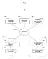
- FIG. 1shows a network system architecture 100 .
- a first client system 105is connected to a first NAT device (network address translation device) 110 , forming a first local or internal network 115 .
- the first client system 105is a network-enabled system, such as a video game console system including a network adapter or a computer system.
- the first client system 105includes hardware and/or software providing video game functionality and hardware and/or software providing network communication as described below.
- the first client system 105is a “Playstation 2”TM game console by Sony Computer Entertainment Inc.TM
- the first NAT device 110is a typical NAT box or NAT server, or alternatively is a type of proxy server or part of a gateway, router, or firewall.
- One or more additional systems or network devicesmay also be connected to the first NAT device 110 and be within the first local network 115 .
- Each system in the first local network 115has a local network address assigned and maintained by the first NAT device 110 .
- a local network address in the first local network 115includes an address number and a port number, such as according to UDP/IP (e.g., where the address number is an IP address).
- the first local network 115uses a different communication protocol and so the local network address includes different information to identify a system.
- the first NAT device 110is connected to an external or public network 120 , such as the Internet.
- Each addressable system or device connected to the external network 120has a public network address.
- a “public” network addressis used on the external network 120 and “local” network addresses are used within local networks, such as the first local network 115 .
- a public network addressincludes an address number and a port number, such as according to UDP/IP.
- the external network 120uses a different communication protocol and so the public network address includes different information to identify a system.
- the local network addresses of the first local network 115are not compatible with the external network 120 (e.g., the local network addresses are not recognizable in the communication protocol of the external network 120 ).
- the first NAT device 110has a public network address.
- the first client system 105is indirectly connected to the external network 120 through the first NAT device 110 and does not have a public network address.
- the first client system 105shares the public network address of the first NAT device 110 with other systems in the first local network 115 (if any are present).
- the first NAT device 110assigns a local network address to each system in the first local network 115 .
- the first NAT device 110translates between the public network address and local network addresses to route data between the external network 120 and the first local network 115 .
- the first NAT device 116has a two or more public network addresses to share among systems in the first local network 115 .
- the first NAT device 110maps port numbers to systems in the first local network 115 , such as by using a PAT technique (Port Address Translation).
- the first NAT device 110assigns a port number to a local system in the first local network 115 when the local system sends data to a destination on the external network 120 .
- the first NAT device 110stores the port number as a port mapping between the port number and the local system.
- the first NAT device 110assigns and stores a single port number for all outgoing data from a single local system.
- the first NAT device 110includes the assigned port number with the outgoing data and so the recipient can use the port number when responding.
- the first NAT device 110determines which system in the first local network 115 is the intended recipient of incoming data by comparing the port number attached to the incoming data with the port mappings stored within the first NAT device 110 .
- the first NAT device 110establishes and adjusts the port mappings dynamically according to data sent and received using the mapping. If the first NAT device 110 does not receive data from a local system or from the external network 120 including a port number for a period of time, the first NAT device 110 releases the port mapping for that port number (a “timeout”). As described below, the first client system 105 can prevent this timeout by periodically sending messages out to the external network 120 .
- the first NAT device 110screens incoming data (e.g., for security reasons) by comparing the network address of the sender of the incoming data with addresses of recipients of data sent by the local system indicated by the port number.
- the first NAT device 110sends data from a local system to a recipient on the external network 120
- the first NAT device 110records the destination address along with the port mapping for the local system.
- the first NAT device 110does not forward incoming data to a local system on the first local network 115 if the local system has not already sent data to a recipient at the same network address as that of the incoming data.
- the first NAT device 110compares the network address of the sender of incoming data with the recorded destination address(es) of outgoing data using the port included with the incoming data. As described above, the first NAT device 110 records destination addresses along with port mappings, so the first NAT device 110 can use a port number as an index to find destination addresses to which data has been sent by a local system. If there is not a match, the first NAT device 110 does not forward the incoming data into the first local network 115 . As described below, the first client system 105 uses this security functionality to “approve” a system on the external network 120 by sending data to that system and so causes the first NAT device 110 to allow data from that approved system into the first local network 115 .
- the first NAT device 110maps a port number to the first client system 105 .
- the first NAT device 110includes the public network address for the first NAT device 110 and the mapped port number for the first client system 105 with the outgoing data.
- the first NAT device 110also records the address of the recipient.
- the first NAT device 110compares the address of the sender with the recorded address of the destination for the previously sent outgoing data. If the addresses match, the first NAT device 110 forwards the data to the first client system 105 using the local network address of the first client system 105 .
- a second client system 125is connected to a second NAT device 130 , forming a second local network 135 .
- the second client system 125is a network-enabled system, such as a video game console system including a network adapter.
- the second NAT device 130is a typical NAT box or NAT server, or alternatively is a type of proxy server or part of a gateway or router.
- the second client system 125 and the second NAT device 130operate similarly to the first client system 105 and the first NAT device 110 , respectively (e.g., in terms of port mapping and screening incoming data).
- One or more additional network devicesmay also be connected to the second NAT device 130 and be within the second local network 135 .
- Each system or device in the second local network 135has a local network address assigned and maintained by the second NAT device 130 , similar to the first local network 115 .
- the first local network 115 and the second local network 135are the same type of network and so use the same communication protocol, however, in alternative implementations, the local networks 115 , 135 can be different types.
- the second NAT device 130is connected to the external network 120 . Accordingly, the second client system 125 is indirectly connected to the external network 120 through the second NAT device 130 .
- the NAT devices 110 , 130can send data to each other through the external network 120 according to the protocols of the external network 120 .
- Each of the server systems 140 , 145 , 150is a network server system, such as a computer system or a mainframe system. Alternatively, some or all of the server systems 140 , 145 , 150 are included within a single system connected to the external network 120 .
- Each of the server systems 140 , 145 , 150has a respective network address on the external network 135 . These server network addresses are known to the client systems 105 , 125 .
- the address server 140assists the client systems 105 , 125 with address discovery.
- the matching server 145assists the client systems 105 , 125 with address sharing.
- the mapping maintenance server 150assists the client systems 105 , 125 with maintaining the address mapping of the NAT devices 110 , 130 , respectively. In an alternative implementation, the maintenance mapping server is omitted.
- FIG. 2is a block diagram of one implementation of a client system 200 , such as first client system 105 in FIG. 1 .
- the client system 200includes four managers: a network address manager 205 , a network registration manager 210 , a network sharing manager 215 , and a network mapping maintenance manager 220 .
- Each of the managers 205 , 210 , 215 , 220is implemented as a software component of the client system 200 .
- some or all of one or more of the mangers 205 , 210 , 215 , 220is implemented in hardware.
- the network address manager 205controls communication between the client system 200 and the address server 140 to discover a public network address associated with the client system 200 by a connected NAT device, such as the first NAT device 10 .
- the network registration manager 210controls communication between the client system 200 and the matching server 145 to register the client system 200 with the matching server 145 .
- the network sharing manager 215controls communication with the matching server 145 to determine the public and local network addresses of another client system that has requested communication with the client system 200 .
- the mapping maintenance manger 220controls communication with the mapping maintenance server 150 to prevent the NAT device connected to the client system 200 from timing out the mapping established for the client system 200 .
- the client system 200does not include a mapping maintenance manager 220 .
- the client system 200includes a network interface 225 for connecting to and communicating with the local network of the client system 200 .
- the network interface 225includes a network communication device, such as a network adapter or modem.
- the client system 200also includes components for general operation, such as a CPU 230 , memory 235 , and an I/O interface 240 .
- the client systemincludes additional video, sound, and application specific software and/or hardware (“game components”).
- game componentssuch as a “Playstation 2”TM by Sony Computer Entertainment Inc.TM including hardware and software for network communication as described herein.
- FIG. 3is a flowchart of establishing and maintaining peer to peer network communication between two client systems, such as the first client system 105 and the second client system 125 in FIG. 1 .
- Each client systemdiscovers its address information, block 305 .
- a client systemsuch as the client systems 105 , 125 in FIG. 1 , has associated address information including a public network address and a local network address.
- a client systemdiscovers its public network address by communicating with the address server (recall the address server 140 in FIG. 1 ).
- a client systemdiscovers its local network address by accessing locally stored information or by querying the corresponding NAT device.
- the client systemsshare their discovered address information with each other, block 310 . As described below referring to FIG.
- one or both of the client systemsregister with the matching server (recall the matching server 145 in FIG. 1 ).
- One of the client systemsrequests communication with the other registered client system and the matching server shares the address information between the client systems.
- the client systemsestablish communication with each other using the received address information, block 315 .
- each client systemsends messages to the other client system using the shared address information so that the NAT devices recognize the incoming messages as “approved.” While the client systems are communicating, the client systems maintain the mapping established by the corresponding NAT devices, block 320 .
- each client systemperiodically sends messages to the mapping maintenance server (recall the mapping maintenance server 150 in FIG. 1 ) so that the corresponding NAT device does not change or timeout the established port mapping for the client system.
- the client systemsdo not maintain this mapping using a mapping maintenance server.
- FIG. 4is a flowchart of a client system discovering its local and public network addresses (recall block 305 of FIG. 3 ).
- the local network addressis the network address of the client system in a local network and is assigned by a NAT device connected to the local network.
- the public network addressis the network address on the external network shared by a NAT device among the systems in the local network connected to the NAT device.
- a local or public network addressincludes an address number and a port number.
- the client systemuses its network address manager component to discover its public and local network addresses (recall network address manager 205 in FIG. 2 ).
- a client systemfirst discovers its local network address, block 405 .
- a client systemdiscovers its local network address by accessing local storage, such as by querying the network stack software used by the client system.
- the client systemestablishes the local port number when the client system initiates communication with the NAT device and so the client system is already aware of the port number.
- the client systemcan request the local network address from the corresponding NAT device.
- the client systemsends an address request to the address server to discover the public network address, block 410 .
- the client systemsends the address request to the address server through the NAT device.
- the NAT deviceadds the public network address to the address request, such as in header information for the address request.
- the NAT deviceassigns a port number and includes the port number in the public network address in the address request (e.g., in the UDP header).
- the address serverextracts the public network address from the address request and stores the public network address, block 415 .
- the public network addressis located within the address request at a known location (e.g., within the header) so the address server can find the public network address in the address request.
- the address serverdoes not store the public network address or only stores the public network address temporarily.
- the address serverreturns the public network address to the client system by generating an address report and sending the address report to the client system, block 420 .
- the address reportincludes the extracted public network address as part of the data or payload of the message as well as in the addressing portion of the message (e.g., in the header).
- the NAT deviceconverts the public network address to the client system's local network address according to the port number and forwards the address report to the client system. For example, the NAT device accesses the port mapping for the client system according to the port number of the public network address and retrieves the local network address. The NAT device then replaces the public network address in the message's header information with the local network address. Accordingly, the NAT device modifies the header by removing the public network address, but does not modify the data portion of the message.
- the client systemreceives the address report and stores the included public network address, block 425 . The client system has now discovered its local and public network addresses.
- FIG. 5is a flowchart of two client systems sharing their local and public network addresses (recall block 310 of FIG. 3 ).
- a first client systemregisters with the matching server, block 505 .
- a client systemuses its network registration manager component to manage registering with the matching server (recall network registration manager 210 in FIG. 2 ).
- the first client systemsends a registration request to the matching server.
- the registration requestincludes the first client system's discovered local and public network addresses.
- the registration requestindicates to the matching server that the sending client system is available for communication using the provided address information.
- the matching serverregisters the first client system in a registry table, block 510 .
- the matching servermaintains a registry table with entries storing address information for registered systems.
- the matching servercreates an entry in the registry table for the first client system and records the provided address information in the entry.
- the second client systemsends a matching request to the matching server, block 515 .
- a client systemuses its network sharing manager component to manage obtaining the address information for another client system from the matching server (recall network sharing manager 215 in FIG. 2 ), both to select a registered client system and to receive address information after registering, as described below.
- the matching requestindicates to the matching server that the second client system is requesting information to establish communication with another client system.
- the matching serversends registry information to the second client system, block 520 . In one implementation, the matching server sends the registry table to the second client system.
- the matching servercommunicates with the second client system so that the second client system can access the registry table to identify a registered client system with which to communicate, such as by accepting search queries from the second client system.
- the second client systemselects the first client system from among the registered client systems, block 525 .
- the second client systemstores the address information for the first client system, block 530 .
- the registry information sent to the second client systemincludes address information for the registered client systems.
- the second client systemseparately requests the address information for the selected client system from the matching server.
- the second client systemsends a matching selection to the matching server, block 535 .
- the matching selectionindicates with which of the registered client systems the second client system is to communicate (in this case, the first client system).
- the matching selectionalso includes the second client system's address information.
- the matching selectionalso serves as a request for the address of the first client system.
- the matching serversends the second client system's address information to the first client system as the selected client system, block 540 .
- the first client systemreceives and records the second client system's address information, block 545 .
- Each of the two client systemshave now shared their address information with the other client system through the matching server.
- FIG. 6is a flowchart of a first client system establishing communication with a second client system (recall block 315 of FIG. 3 ).
- the first client systemsends one or more test messages to the second client system, block 605 .
- the first client systemsends some of the test messages to the second client system using the public network address for the second client system (outgoing public address test messages) and some of the test messages using the local network address for the second client system (outgoing local address test messages).
- the first client systemreceived the public and local network addresses for the second client system when the two client systems shared address information (recall FIG. 5 ).
- the first client systemdoes not send test messages using the local network address.
- the first client systemcontinues to send test messages to the second client system until the first client system receives a confirmation message from the second client system in block 630 , as described below.
- the NAT device connected to the first client systemrecords the destination addresses of the outgoing test messages, block 610 .
- the NAT device connected to the first client system(e.g., the first NAT device 110 in FIG. 1 ) is a gateway between the local network of the first client system and the external network. Accordingly, the outgoing test messages pass through the NAT device. As described above, the NAT device screens incoming data and does not allow data to enter the NAT device's local network unless the local network destination of the incoming data has already attempted to communicate with the sender of the incoming data.
- the NAT devicerecords the destination address of outgoing data from the systems on the local network as “approved” addresses for the sender of the outgoing data.
- the NAT devicecompares the origin address of the incoming data (i.e., the address of the sender) with recorded “approved” addresses for the intended recipient on the local network.
- the NAT deviceonly forwards incoming data to the local recipient when the origin address matches one of the “approved” addresses for the local recipient.
- the NAT devicerecords the destination addresses of the outgoing test messages as “approved” addresses of systems with which the first client system is attempting to communicate.
- the NAT devicereceives data for the first client system that is from the same address as the destination address of one of the first client system's outgoing test messages, the NAT device forwards the incoming data to the first client system.
- the first client systemis sending test messages to addresses for the second client system, so the NAT device will forward data from the second client system to the first client system.
- the second client systemWhile the first client system is sending test messages to the second client system, the second client system is sending test messages to the first client system as well, as described below referring to FIG. 7 .
- the second client systemsends outgoing public address test messages (and outgoing local address test messages if appropriate) using the address information for the first client system.
- the NAT device connected to the second client systeme.g., the second NAT device 130 in FIG. 1 ) records the destination addresses for the outgoing test messages and so will forward incoming data for the second client system received from the first client system.
- the first client systemreceives a test message from the second client system, block 615 .
- the NAT device connected to the first client systemforwards an incoming test message from the second client system to the first client system because the NAT device matches the origin address of the incoming test message with a recorded “approved” address.
- the first client systemrecords the origin address of the received test message, block 620 .
- the first client systemsends a confirmation message to the second client system using the recorded origin address, block 625 .
- the outgoing confirmation messageindicates to the second client system that the first client system has received a test message from the second client system.
- the second client systemreceives a test message from the first client system and sends a confirmation message to the first client system using the origin address of that test message.
- the first client systemreceives a confirmation message from the second client system, block 630 .
- the first client systemstops sending test messages to the second client system.
- the first client systemhas now established communication with the second client system.
- the second clientAfter the second client receives the confirmation message from the first client system, the second client system will have established communication with the first client system.
- the client systemshave confirmed an address to which each system can send data and have that data successfully pass through the NAT device of the recipient system.
- the first client systemBy first sending test messages addressed to the second client system so that the NAT device will forward messages from the second client system to the first client system, the first client system is “punching holes” in the security features of the NAT device. Accordingly, this technique is referred to as “hole punching.” Using “hole punching” the first and second client systems can establish communication without altering the operation of the NAT devices.
- FIG. 7is a flowchart of the second client system establishing communication with the first client system. The actions of FIG. 7 occur in conjunction with those described above referring to FIG. 6 .
- the second client systemsends test messages to the first client system using the address information received when the client systems shared address information, block 705 .
- the second client systemsends outgoing public address test messages using the first client system's public network address and also sends outgoing local address test messages if the local network address is compatible with the external network.
- the second client systemcontinues to send test messages to the first client system until the second client system receives a confirmation message from the first client system in block 730 , as described below.
- the NAT device connected to the second client systemrecords the destination addresses for the outgoing test messages as “approved” addresses, block 710 .
- the first client systemis also sending test messages to the second client system and the second client system receives a test message from the first client system, block 715 .
- the second client systemrecords the origin address of the received test message, block 720 , and sends a confirmation message to the first client system using the origin message, block 725 .
- the first client systemalso sends a confirmation message to the second client system after receiving a test message from the second client system and the second client system receives the confirmation message, block 730 .
- the second client systemstops sending test messages to the first client system.
- the second client systemhas now established communication with the first client system.
- FIG. 8is a flowchart of a client system maintaining the mapping assigned by a connected NAT device (recall block 315 of FIG. 3 ).
- a client systemuses its network mapping maintenance manager component to manage maintaining the address mapping of a connected NAT device with the mapping maintenance server (recall network mapping maintenance manager 220 in FIG. 2 ).
- a NAT deviceassigns local network addresses to the systems on the local network of the NAT device.
- the NAT devicealso assigns port numbers for the public network address used by local systems.
- the NAT deviceassigns a port number to the local system and stores the port number.
- the NAT deviceWhen the NAT device receives incoming data, the NAT device checks the port number in the target address for the incoming data (e.g., in the header information) to determine which local system is the intended recipient. As described above the NAT device also uses the port number to confirm that the sender of the incoming data is “approved” before forwarding the data to the local system. Once the NAT device has assigned a port number to a local system, the NAT device begins counting down a timer. If the local system sends more data to the external network, the NAT device uses the same port number and resets the timer. Similarly, if the NAT device receives incoming data using the port number, the NAT device resets the timer.
- mapping maintenance serveris included within the address server or the matching server and so the client system sends mapping maintenance messages to the appropriate server. In one implementation not including a mapping maintenance server, the client system does not send mapping maintenance messages.
- the client systemsends a mapping maintenance message to the mapping maintenance server through the connected NAT device, block 805 .
- the first client system 105sends a mapping maintenance message through the first NAT device 110 to the mapping maintenance server 150 .
- the NAT devicereceives the mapping maintenance message and resets the timer for the port number assigned to the client system, block 810 .
- the NAT devicesends the mapping maintenance message to the mapping maintenance server, block 815 .
- the client systemevaluates whether to maintain the current address, block 820 . If the client system is communicating with another client system or attempting to communicate with another client system, the client system sends another mapping maintenance to the mapping maintenance server to preserve the current port mapping, returning to block 805 .
- the client systemdoes not send another mapping maintenance message and allows the port mapping to timeout, block 825 .
- the mapping maintenance serverdoes not respond to the client system.
- the mapping maintenance serversends a mapping maintenance confirmation message to the client system.
- FIGS. 9A-9Cshow alternative network configurations.
- a first client system 905is behind a NAT device 910 while a second client system 915 is not connected to a NAT device.
- both client systems 930 , 935are not connected to NAT devices.
- both client systems 970 , 975are behind the same NAT device 980 in the same local network 985 .
- the client systems and server systemscan interact in substantially the same way as described above.
- This sectiondescribes evaluating network configurations.
- a configuration serveranalyzes address information received from a client system to evaluate the network connected to the client system.
- the configuration serverdetermines whether or not there is a NAT device between the client system and the configuration server.
- the configuration serveralso evaluates other information, such as what type of NAT device is present or information about other systems in the client system's local network.
- a local or public network addressincludes an address number and a port number.
- the local network addressis the network address of the client system in a local network formed by the NAT device and the client system (and possibly additional systems).
- the local network addressis assigned to the client system by the NAT device.
- the public network addressis the network address on the external network shared by the NAT device among the systems in the local network connected to the NAT device.
- the NAT devicehas a pool of public network addresses to share among local systems.
- the NAT devicemodifies the message before sending the message out to the external network.
- the client systemincludes the local network address in the message, such as in header information indicating the source address of the message.
- the NAT deviceadds the public network address to the address message, such as by replacing the local network address in the header with the public network address.
- port numbersif the NAT device has not already assigned a port number to the client system, the NAT device assigns a port number and includes the port number in the public network address in the address message (e.g., in the UDP header).
- the client system's local network address and public network addressare the same. Without a NAT device, the network address used by the client system within the local network is the same network address used by the client system in the external network.
- the header information indicating the source address of the messagedoes not change from what the client system set the source address to.
- a configuration serveruses address information received from a client system to evaluate the client system's network.
- the configuration serverreceives the local network address and the public network address of a client system and then evaluates the addresses to determine or estimate whether a NAT device is present or not, including comparing the addresses.
- the configuration serverstores the addresses and the address evaluation for various purposes, such as for marketing information or for technical support.
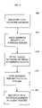
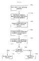
- FIG. 10is a flowchart of a configuration server evaluating the network configuration for a client system.
- the configuration serverreceives an address message from a client system, block 1005 .
- the address messageincludes address information from the client system, such as the client system's local network address and public network address.
- the configuration serversends a request to the client system for an address message (e.g., after establishing communication with the client system) and the client system sends the address message to the configuration server in response to the request.
- the configuration serverextracts the address information from the address message and stores the address information, block 1010 .
- the configuration serverevaluates the extracted address information. block 1015 .
- the configuration serveruses the address information to determine characteristics of the client system's network configuration. For example, as described below, when the local network address and public network address extracted from the address message are different, the configuration server determines that the message from the client system passed through a NAT device. In another example, by collecting information from multiple client systems about how many client systems are connected to NAT devices, the configuration server builds information about NAT device use, such as for marketing. Multiple configuration servers can also share information or provide their information and evaluations to a common location or organization, such as an evaluation server for collecting and evaluating evaluation information for multiple client systems. In another implementation, the configuration server sends evaluation information back to the client system.
- the client systemsends local network information to the configuration server in addition to or instead of the address messages.
- the local network informationincludes information about the local network of the client system.
- the client systemcollects information about other systems connected to the local network, such as how many or what types of systems are connected to the local network (e.g., using broadcast messaging, inspecting network “cookies,” using system administration tools).
- the local network informationincludes one or more network cookies from the client system.
- the local network informationincludes information collected by the client system by querying the other local systems or the NAT device such as by using requests according to a protocol such as UPnP (universal plug and play).
- the configuration servercan also use the local network information in evaluating the client system's network configuration and operation.
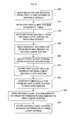
- FIG. 11is a flowchart of one implementation of evaluating the network configuration for a client system by comparing local and public network addresses.
- FIG. 11provides a view of operations throughout the system.
- the client systemdiscovers its local network address, block 1105 .
- a client systemdiscovers its local network address by accessing local storage, such as by querying the network stack software used by the client system.
- the client systemestablishes the local port number when the client system initiates communication with a NAT device or other network gateway and so the client system is already aware of the port number.
- the client systemcan request the local network address.
- the local network addressmay be the same as the public network address, such as when there is no NAT device present.
- the client systemgenerates an address message including the local network address of the client system, block 1110 .
- the client systemstores the local network address in the data or payload portion of the address message.
- the client systemalso includes additional information identifying the client system, such as a serial number or a MAC address.
- the client systemsends the address message to the configuration server through the external network, block 1115 .
- the NAT devicemodifies the address message before sending the address message out to the external network.
- the NAT deviceadds the public network address to the address message, such as in header information indicating the source address of the address message. If the NAT device has not already assigned a port number to the client system, the NAT device assigns a port number and includes the port number in the public network address in the address message (e.g., in the UDP header).
- the configuration serverextracts the public network address from the address message and stores the public network address, block 1120 .
- the public network addressis located within the address message at a known location (e.g., within the header) so the configuration server can find the public network address in the address message.
- the configuration serverextracts the source address of the address message and stores this source address as the public network address for the client system.
- the configuration serverdoes not store the public network address or only stores the public network address temporarily.
- the configuration serverextracts the local network address from the address message and stores the local network address, block 1125 .
- the local network addressis located within the address message at a known location (e.g., within the payload) so the configuration server can find the local network address in the address message.
- the configuration serverdoes not store the local network address or only stores the local network address temporarily.
- the configuration servercompares the extracted addresses, block 1130 .
- a NAT device between the client system and the configuration serversets the source address of an outgoing message from the client system to the public network address of the NAT device.
- the public network addressis different from the local network address. Accordingly, if the public network address and the local network address are the same, the configuration server determines that there is no NAT device present between the client system and the configuration server, block 1135 . If the public network address and the local network address are not the same, the configuration server determines that there is a NAT device present between the client system and the configuration server, block 1140 .
- the evaluationis not necessarily determinative and may only provide a guideline or estimate.
- NAT devicesprovide a public network address to a client system as a local network address and so the local network address and public network address for a client will be the same even though there is an intervening NAT device (e.g., in some implementations of a “demilitarized zone” or “DMZ” in a NAT device).
- intervening NAT devicee.g., in some implementations of a “demilitarized zone” or “DMZ” in a NAT device.
- the configuration servercan gather information from multiple client systems to evaluate the number of NAT devices being used by client systems. This information can provide valuable marketing insights related to NAT device penetration among the client systems. For example, NAT device penetration can be indicative of router use (e.g., because routers often provide NAT functionality in home networks), local network penetration (e.g., NAT device presence often indicates a local network of more than one device or system has been established), broadband penetration (e.g., NAT devices may be more commonly used with broadband connections, such as ISDN, cable modems, DSL modems, etc.). Furthermore, categorizing a particular client system as being connected to a NAT device or not can provide useful marketing information as well. For example, a user of a client system connected to a NAT device may be a desirable target in targeted marketing, such as for home networking products or services. Similarly, a user without a NAT device may be a desirable target for advertising a NAT device.
- NAT device penetrationcan be indicative of router use (e.g., because router
- the configuration serverperforms additional evaluation of the address information.
- the configuration serverevaluates additional information or combinations of information about the client system's network configuration, such as the local network information described above.
- the configuration serverdetermines a NAT device is present, the configuration server estimates what type of NAT device is being used. Because the NAT device assigns the local network address to the client system, the local network address provides information about the NAT device. The address allocation pattern shows device type information. For example, some manufacturers, brands, or models of NAT devices may use unique local network addresses. Accordingly, the configuration server includes a NAT device table of addresses used as local network addresses of one or more NAT device manufacturers (or brands, models, etc.). The configuration server compares the local network address with the table entries to determine if the NAT device matches one of the entries.
- one NAT device tableindicates that a NAT device made by manufacturer A uses an IP address of 192.168.0.x for local network addresses (where 192, 168, and 0 are fixed values and “x” indicates a free value in the addresses used) while manufacturer B uses an IP address of 192.168.128.x.
- the address allocation patternsmay also apply to public network addresses and port mappings. In addition to brand, the address allocation can also show model of NAT device or the version of firmware being run by the NAT device.
- the device type informationmay also provide insight into types of broadband use (e.g., DSL versus cable modems) according to the compatibility of the brand or model.
- a technical support serverincludes a configuration server and has collected device type information for a client system.
- the technical support serveralready has an estimate of what type of NAT device is connected to the client system.
- the configuration serverevaluates the number of local systems connected to the client system's NAT device (though this may not be determinative).
- the configuration serveranalyzes the public network address or the local network address and estimates how many other devices may be using the same NAT device. For example, when a client system's local network address is 192.168.1.5, the configuration server estimates that the client system is the sixth system or device connected to the NAT device, as local network addresses 192.168.1.0 through 192.168.1.4 appear to have been allocated elsewhere.
- the configuration serverestimates that the NAT device has used the fourth public network address of a pool of public network addresses for the client system and so four other systems or devices are connected to the NAT device.
- a configuration servercan evaluate port numbers in addresses in a similar way.
- the address server 140 described above in Section 1 referring to FIG. 1is also or includes a configuration server as described in Section 2.
- This address-configuration server 140includes components, such as additional hardware, software, or a combination of both, to evaluate the network configuration of the first local network 115 or the second local network 135 .
- the address request from the first client system 105also serves as an address message for the address server 140 , and the address server 140 evaluates the network configuration of the first local network 115 , as described above.
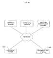
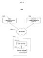
- FIG. 12shows another implementation of a network system 1200 including a configuration server.
- This network architecture 1200is similar to the network architecture 100 described above referring to FIG. 1 , however, the only server is a configuration server 1225 .
- a client system 1205is connected to a NAT device 1210 , forming a local network 1215 .
- the client system 1205 in the local network 1215has a local network address assigned and maintained by the NAT device 1210 .
- the NAT device 1210is connected to an external or public network 1220 , such as the Internet, and has a public network address.
- a configuration server 1225is also connected to the external network 1220 .
- the configuration server 1225operates as described above referring to FIGS. 10 and 11 .
- the client system 1205 and the configuration server 1225communicate through the external network 1220 and the NAT device 1210 and the configuration server 1225 evaluates the configuration of the local network 1215 using address information received from the client system 1205 .
- the configuration server 1225is a network system (e.g., including a computer and performing additional operations beyond network configuration evaluation), while in another implementation, the configuration server 1225 is a special-purpose network device.
- Some NAT devicesare destination dependent NAT devices and map a different public network address to a client system for each different destination of data from a client system.
- a destination dependent NAT devicehas a pool of public network addresses (or a pool of port numbers).
- the destination dependent NAT deviceassigns a first public network address to the client system and uses that first public network address in communicating between the client system and the first destination.
- the client systemsends a message to a second destination (having a different public network address than that of the first destination)
- the destination dependent NAT deviceassigns a second public network address to the client system and uses that second public network address in communicating between the client system and the second destination.
- a NAT deviceis a destination dependent NAT address, such as for marketing or technical support as described above, or for compatibility with functions or software of the client system or another server.
- FIG. 13shows another implementation of a network system 1300 including two configuration servers.
- This network architecture 1300is similar in structure to the network architecture 1200 described above referring to FIG. 12 , however, two configuration servers 1325 and 1330 are connected to the external network 1320 .
- a client system 1305is connected to a NAT device 1310 , forming a local network 1315 .
- the client system 1305 in the local network 1315has a local network address assigned and maintained by the NAT device 1310 .
- the NAT device 1310is connected to an external or public network 1320 , such as the Internet, and has at least one public network address.
- a first configuration server 1325 and a second configuration server 1330are also connected to the external network 1320 .
- the first configuration server 1325 and the second configuration server 1330each have a respective public network address.
- the two configuration servers 1325 , 1330are part of the same server (e.g., as separate components or subsystems), but the one configuration server then has two public network addresses.
- the client system 1305 and the configuration servers 1325 , 1330communicate through the external network 1320 and the NAT device 1310 .
- the configuration servers 1325 , 1330evaluate the configuration of the local network 1315 using address information received from the client system 1305 , including determining whether the NAT device 1310 is a destination dependent NAT device 1310 .
- FIG. 14is a flowchart of using two configuration servers in evaluating whether a NAT device is a destination dependent NAT device, such as using the configuration servers 1325 , 1330 described above referring to FIG. 13 .
- the first configuration serverevaluates the local network of the client system, block 1405 .
- the first configuration serverevaluates the local network of the client system as described above referring to FIGS. 10 and 11 .
- the configuration serverreceives local and public network addresses from a client system and determines whether a NAT device is present.
- the second configuration serverevaluates the local network of the client system, block 1410 .
- the second configuration serverperforms its evaluation before or after the first configuration server, or in parallel. At this point, both of the configuration servers have received a public network address from the client system.
- the configuration serverscompare the public network addresses received, block 1415 .
- One of the configuration serverssends the received public network address to the other configuration server over the external network.
- the configuration serversare directly connected or connected in a local or private network.
- the first configuration server 1325sends the public network address received from the client system 1305 to the second configuration server 1330 through the external network 1320 .
- the second configuration server 1330compares the public network address received from the first configuration server 1325 with the public network address received by the second configuration server 1330 from the client system 1305 .
- the NAT deviceis a destination dependent NAT device
- the destination dependent NAT devicewhen the client system sends an address message to the different configuration servers, the destination dependent NAT device inserts a different public network address in the outgoing address messages. If the NAT device is not a destination dependent NAT device (i.e., it is a “destination independent” NAT device), the NAT device uses the same public network address for the client system's outgoing messages, including the address messages to the different configuration servers.
- the configuration serverscompare the received public network addresses, if the two public network addresses are the same, then the NAT device is not a destination dependent NAT device, block 1420 . If the two public network addresses are different, then the NAT device is a destination dependent NAT device, block 1425 .
- One or both of the configuration serversstores the result of the evaluation of the NAT device. As described above, the result and the pattern of public network address allocation in a destination dependent NAT device can be used for marketing and to predict or estimate aspects of the NAT device, such as brand or model. Again, the evaluation is not always determinative as many types of NAT devices are available.
- a configuration serverreceives regular address messages from a client system to evaluate if a connected NAT device is changing the mapping of the client system.
- some NAT devicesmay “time out” a mapping after a period and assign a different public network address to a client system.
- the configuration servercan evaluate if the public network address assigned to the client system by the NAT device has changed or how often the mapping changes.
- the configuration servercan also use this evaluation to estimate the type of the NAT device (e.g., certain models do not change mappings, while others change mappings at known periods, or have known “time out” periods).
- each computerincludes one or more processors, one or more data-storage components (e.g., volatile or non-volatile memory modules and persistent optical and magnetic storage devices, such as hard and floppy disk drives, CD-ROM drives, and magnetic tape drives), one or more input devices (e.g., mice and keyboards), and one or more output devices (e.g., display consoles and printers).
- the computer programsinclude executable code that is usually stored in a persistent storage medium and then copied into memory at run-time.
- the processorexecutes the code by retrieving program instructions from memory in a prescribed order.
- the computerreceives data from the input and/or storage devices, performs operations on the data, and then delivers the resulting data to the output and/or storage devices.
Landscapes
- Engineering & Computer Science (AREA)
- Computer Networks & Wireless Communication (AREA)
- Signal Processing (AREA)
- Computer Security & Cryptography (AREA)
- Data Exchanges In Wide-Area Networks (AREA)
- Small-Scale Networks (AREA)
Abstract
Description
Claims (35)
Priority Applications (10)
| Application Number | Priority Date | Filing Date | Title |
|---|---|---|---|
| US10/295,542US7243141B2 (en) | 2002-05-13 | 2002-11-15 | Network configuration evaluation |
| DE60336052TDE60336052D1 (en) | 2002-05-13 | 2003-05-12 | NETWORK CONFIGURATION ANALYSIS |
| EP03726789AEP1504586B1 (en) | 2002-05-13 | 2003-05-12 | Network configuration evaluation |
| PCT/US2003/014810WO2003096654A1 (en) | 2002-05-13 | 2003-05-12 | Network configuration evaluation |
| KR1020047006968AKR100708020B1 (en) | 2002-05-13 | 2003-05-12 | Network configuration evaluation |
| AU2003229009AAU2003229009B8 (en) | 2002-05-13 | 2003-05-12 | Network configuration evaluation |
| AT03726789TATE498970T1 (en) | 2002-05-13 | 2003-05-12 | NETWORK CONFIGURATION EVALUATION |
| JP2004504488AJP3868449B2 (en) | 2002-05-13 | 2003-05-12 | Peer-to-peer network communication by network address translation (NAT) |
| CN038017296ACN1602617B (en) | 2002-05-13 | 2003-05-12 | Evaluation of Network Configuration |
| TW092112958ATWI242954B (en) | 2002-05-13 | 2003-05-13 | Method of evaluating a network configuration and tangible storage medium for storing a computer program of evaluating a network configuration |
Applications Claiming Priority (3)
| Application Number | Priority Date | Filing Date | Title |
|---|---|---|---|
| US38039602P | 2002-05-13 | 2002-05-13 | |
| US10/215,899US7676579B2 (en) | 2002-05-13 | 2002-08-08 | Peer to peer network communication |
| US10/295,542US7243141B2 (en) | 2002-05-13 | 2002-11-15 | Network configuration evaluation |
Related Parent Applications (1)
| Application Number | Title | Priority Date | Filing Date |
|---|---|---|---|
| US10/215,899Continuation-In-PartUS7676579B2 (en) | 2002-05-13 | 2002-08-08 | Peer to peer network communication |
Publications (2)
| Publication Number | Publication Date |
|---|---|
| US20030212772A1 US20030212772A1 (en) | 2003-11-13 |
| US7243141B2true US7243141B2 (en) | 2007-07-10 |
Family
ID=29424437
Family Applications (1)
| Application Number | Title | Priority Date | Filing Date |
|---|---|---|---|
| US10/295,542Expired - LifetimeUS7243141B2 (en) | 2002-05-13 | 2002-11-15 | Network configuration evaluation |
Country Status (9)
| Country | Link |
|---|---|
| US (1) | US7243141B2 (en) |
| EP (1) | EP1504586B1 (en) |
| JP (1) | JP3868449B2 (en) |
| KR (1) | KR100708020B1 (en) |
| CN (1) | CN1602617B (en) |
| AT (1) | ATE498970T1 (en) |
| AU (1) | AU2003229009B8 (en) |
| TW (1) | TWI242954B (en) |
| WO (1) | WO2003096654A1 (en) |
Cited By (28)
| Publication number | Priority date | Publication date | Assignee | Title |
|---|---|---|---|---|
| US20040117834A1 (en)* | 2002-12-11 | 2004-06-17 | Jeyhan Karaoguz | Server architecture supporting a personal media exchange network |
| US20050111454A1 (en)* | 2003-11-25 | 2005-05-26 | Narjala Ranjit S. | Method, apparatus and system for intelligently and dynamically routing mobile internet protocol packets |
| US20050113109A1 (en)* | 2003-11-25 | 2005-05-26 | Farid Adrangi | Method, apparatus and system for context-based registrations based on intelligent location detection |
| US20050136924A1 (en)* | 2003-12-04 | 2005-06-23 | Farid Adrangi | Method, apparatus and system for enabling roaming mobile nodes to utilize private home IP addresses |
| US20050177646A1 (en)* | 2003-03-28 | 2005-08-11 | Sony Corporation | Network system and communication method, and information processing apparatus, method and program |
| US20050259600A1 (en)* | 2004-05-18 | 2005-11-24 | Samsung Electronics Co., Ltd. | Translation bridge between ethernet and 1394A local links for consumer electronics devices |
| US20060209794A1 (en)* | 2004-08-13 | 2006-09-21 | Bae Kiwan E | Method and system for providing interdomain traversal in support of packetized voice transmissions |
| US20060280127A1 (en)* | 2004-06-07 | 2006-12-14 | Nippon Telegraph And Telephone Corp | Domestic network setting method, home gateway device, home gateway program, and recording medium |
| US20080126528A1 (en)* | 2003-01-15 | 2008-05-29 | Matsushita Electric Industrial Co., Ltd. | PEER-TO-PEER (P2P) CONNECTION DESPITE NETWORK ADDRESS TRANSLATORS (NATs) AT BOTH ENDS |
| US20080196098A1 (en)* | 2004-12-31 | 2008-08-14 | Cottrell Lance M | System For Protecting Identity in a Network Environment |
| US7433325B1 (en)* | 2006-05-09 | 2008-10-07 | Cisco Technology, Inc. | NAT and proxy device detection |
| US20080298376A1 (en)* | 2007-05-30 | 2008-12-04 | Sony Computer Entertainment Inc. | Network communication with path mtu size discovery |
| US20080320116A1 (en)* | 2007-06-21 | 2008-12-25 | Christopher Briggs | Identification of endpoint devices operably coupled to a network through a network address translation router |
| US7535878B2 (en) | 2003-03-28 | 2009-05-19 | Intel Corporation | Method, apparatus and system for ensuring reliable access to a roaming mobile node |
| US20090138928A1 (en)* | 2002-12-11 | 2009-05-28 | Broadcom Corporation | Media processing system based on satellite set top box platform with telephony downstream and upstream data paths |
| US7542466B2 (en) | 2003-11-14 | 2009-06-02 | Sony Corporation | System and method of information communication, information processing apparatus and information processing method, program and recording medium |
| US20090144806A1 (en)* | 2007-12-03 | 2009-06-04 | Cisco Technology, Inc. | Handling of DDoS attacks from NAT or proxy devices |
| US20090210556A1 (en)* | 2005-05-31 | 2009-08-20 | Access Co., Ltd | Time division address management device and time division routing information management device |
| US7580396B2 (en) | 2003-11-05 | 2009-08-25 | Intel Corporation | Method, apparatus and system for obtaining and retaining a mobile node home address |
| WO2010033620A1 (en)* | 2008-09-22 | 2010-03-25 | Sony Computer Entertainment America Inc. | Method for host selection based on discovered nat type |
| US8028093B2 (en) | 2002-12-11 | 2011-09-27 | Broadcom Corporation | Media processing system supporting adaptive digital media parameters based on end-user viewing capabilities |
| US8171123B2 (en) | 2007-12-04 | 2012-05-01 | Sony Computer Entertainment Inc. | Network bandwidth detection and distribution |
| US8176530B2 (en) | 2002-12-11 | 2012-05-08 | Broadcom Corporation | Preventing a non-head end based service provider from sending media to a media processing system |
| US8224985B2 (en) | 2005-10-04 | 2012-07-17 | Sony Computer Entertainment Inc. | Peer-to-peer communication traversing symmetric network address translators |
| US20130091272A1 (en)* | 2011-10-06 | 2013-04-11 | Av Tech Corporation | Network Connection Status Detection System and Method Thereof |
| US8516257B2 (en) | 2002-12-11 | 2013-08-20 | Broadcom Corporation | Secure media peripheral association in a media exchange network |
| US9357256B2 (en) | 2002-12-11 | 2016-05-31 | Broadcom Corporation | Third party media channel access in a media exchange network |
| US9667636B2 (en)* | 2015-04-27 | 2017-05-30 | Cisco Technology, Inc. | Detecting network address translation devices in a network based on network traffic logs |
Families Citing this family (52)
| Publication number | Priority date | Publication date | Assignee | Title |
|---|---|---|---|---|
| GB2362482A (en)* | 2000-05-15 | 2001-11-21 | Ridgeway Systems & Software Lt | Direct slave addressing to indirect slave addressing |
| GB2365256A (en) | 2000-07-28 | 2002-02-13 | Ridgeway Systems & Software Lt | Audio-video telephony with port address translation |
| GB2369746A (en)* | 2000-11-30 | 2002-06-05 | Ridgeway Systems & Software Lt | Communications system with network address translation |
| US7333500B2 (en)* | 2002-09-24 | 2008-02-19 | Nortel Networks Limited | Methods for discovering network address and port translators |
| US7184934B2 (en)* | 2003-06-26 | 2007-02-27 | Microsoft Corporation | Multifaceted system capabilities analysis |
| JP4633520B2 (en)* | 2004-04-05 | 2011-02-16 | パナソニック株式会社 | Communication apparatus, method, and program for realizing P2P communication |
| US7480736B2 (en)* | 2004-04-12 | 2009-01-20 | Emerson Network Power - Embedded Computing, Inc. | Method of discovering and operating a payload node |
| DE602005027061D1 (en)* | 2004-04-23 | 2011-05-05 | Panasonic Corp | SERVER DEVICE, CLIENT DEVICE AND NETWORK SYSTEM |
| SE534807C2 (en)* | 2004-05-14 | 2011-12-27 | Klap Worldwide Corp Trident Chambers | Mobile communication network for providing a mobile station with a fixed IP address |
| US8050272B2 (en) | 2004-06-29 | 2011-11-01 | Damaka, Inc. | System and method for concurrent sessions in a peer-to-peer hybrid communications network |
| US8009586B2 (en) | 2004-06-29 | 2011-08-30 | Damaka, Inc. | System and method for data transfer in a peer-to peer hybrid communication network |
| US7933260B2 (en) | 2004-06-29 | 2011-04-26 | Damaka, Inc. | System and method for routing and communicating in a heterogeneous network environment |
| US7570636B2 (en)* | 2004-06-29 | 2009-08-04 | Damaka, Inc. | System and method for traversing a NAT device for peer-to-peer hybrid communications |
| US8437307B2 (en) | 2007-09-03 | 2013-05-07 | Damaka, Inc. | Device and method for maintaining a communication session during a network transition |
| JP4312136B2 (en)* | 2004-09-17 | 2009-08-12 | 三洋電機株式会社 | Command processing unit |
| US8880612B1 (en)* | 2004-12-16 | 2014-11-04 | Sprint Spectrum L.P. | Mobile device proxy for instant messaging |
| KR100727993B1 (en)* | 2005-10-04 | 2007-06-14 | 삼성전자주식회사 | Data push service method and system using data pull method |
| JP2007201564A (en)* | 2006-01-23 | 2007-08-09 | Nec Corp | Estimate system, terminal, estimate method, and program |
| EP1916816A1 (en)* | 2006-10-26 | 2008-04-30 | Alcatel Lucent | Method and devices to establish a public communication session |
| US7764691B2 (en)* | 2007-03-15 | 2010-07-27 | Microsoft Corporation | Allowing IPv4 clients to communicate using teredo addresses when both clients are behind a NAT |
| US7715386B2 (en)* | 2007-03-15 | 2010-05-11 | Microsoft Corporation | Reducing network traffic to teredo server |
| US8194683B2 (en)* | 2007-03-30 | 2012-06-05 | Microsoft Corporation | Teredo connectivity between clients behind symmetric NATs |
| WO2009043016A2 (en) | 2007-09-28 | 2009-04-02 | Damaka, Inc. | System and method for transitioning a communication session between networks that are not commonly controlled |
| US8380859B2 (en) | 2007-11-28 | 2013-02-19 | Damaka, Inc. | System and method for endpoint handoff in a hybrid peer-to-peer networking environment |
| US8311063B2 (en) | 2008-03-28 | 2012-11-13 | Silver Spring Networks, Inc. | Updating routing and outage information in a communications network |
| US9614685B2 (en)* | 2009-03-09 | 2017-04-04 | Nokia Technologies Oy | Methods, apparatuses, and computer program products for facilitating synchronization of setting configurations |
| CN104821891B (en)* | 2009-11-23 | 2018-11-30 | 皇家Kpn公司 | method and system for remote device management |
| US8725895B2 (en) | 2010-02-15 | 2014-05-13 | Damaka, Inc. | NAT traversal by concurrently probing multiple candidates |
| US8874785B2 (en) | 2010-02-15 | 2014-10-28 | Damaka, Inc. | System and method for signaling and data tunneling in a peer-to-peer environment |
| US8892646B2 (en) | 2010-08-25 | 2014-11-18 | Damaka, Inc. | System and method for shared session appearance in a hybrid peer-to-peer environment |
| JP2011176383A (en)* | 2010-02-23 | 2011-09-08 | Brother Industries Ltd | Communication device, communication system, communication method and communication program |
| US9043488B2 (en) | 2010-03-29 | 2015-05-26 | Damaka, Inc. | System and method for session sweeping between devices |
| US9191416B2 (en) | 2010-04-16 | 2015-11-17 | Damaka, Inc. | System and method for providing enterprise voice call continuity |
| US8352563B2 (en) | 2010-04-29 | 2013-01-08 | Damaka, Inc. | System and method for peer-to-peer media routing using a third party instant messaging system for signaling |
| US8611540B2 (en) | 2010-06-23 | 2013-12-17 | Damaka, Inc. | System and method for secure messaging in a hybrid peer-to-peer network |
| US8583748B2 (en)* | 2010-09-01 | 2013-11-12 | At&T Mobility Ii, Llc | Method and apparatus for messaging service internetworking |
| US8468010B2 (en) | 2010-09-24 | 2013-06-18 | Damaka, Inc. | System and method for language translation in a hybrid peer-to-peer environment |
| US8743781B2 (en) | 2010-10-11 | 2014-06-03 | Damaka, Inc. | System and method for a reverse invitation in a hybrid peer-to-peer environment |
| US8407314B2 (en) | 2011-04-04 | 2013-03-26 | Damaka, Inc. | System and method for sharing unsupported document types between communication devices |
| US8694587B2 (en) | 2011-05-17 | 2014-04-08 | Damaka, Inc. | System and method for transferring a call bridge between communication devices |
| US8862702B2 (en)* | 2012-07-18 | 2014-10-14 | Accedian Networks Inc. | Systems and methods of installing and operating devices without explicit network addresses |
| US9027032B2 (en) | 2013-07-16 | 2015-05-05 | Damaka, Inc. | System and method for providing additional functionality to existing software in an integrated manner |
| US9357016B2 (en) | 2013-10-18 | 2016-05-31 | Damaka, Inc. | System and method for virtual parallel resource management |
| US9276841B2 (en)* | 2014-01-31 | 2016-03-01 | Edgecast Networks, Inc. | Adapting network control messaging for anycast reliant platforms |
| CA2956617A1 (en) | 2014-08-05 | 2016-02-11 | Damaka, Inc. | System and method for providing unified communications and collaboration (ucc) connectivity between incompatible systems |
| JP6507572B2 (en)* | 2014-10-31 | 2019-05-08 | 富士通株式会社 | Management server route control method and management server |
| US10091025B2 (en) | 2016-03-31 | 2018-10-02 | Damaka, Inc. | System and method for enabling use of a single user identifier across incompatible networks for UCC functionality |
| US10594829B2 (en)* | 2017-05-24 | 2020-03-17 | At&T Intellectual Property I, L.P. | Cloud workload proxy as link-local service configured to access a service proxy gateway via a link-local IP address to communicate with an external target service via a private network |
| EP3769493B1 (en)* | 2018-03-23 | 2022-11-09 | Signify Holding B.V. | A method of and devices for performing an over-the-air, ota, upgrade in a network of communicatively interconnected devices |
| US11159420B2 (en)* | 2019-04-17 | 2021-10-26 | Cloudflare, Inc. | Method and apparatus of automatic route optimization in a private virtual network for client devices of a local network |
| CN116455863A (en)* | 2022-01-05 | 2023-07-18 | 西安西电捷通无线网络通信股份有限公司 | NAT detection method, device and storage medium between network nodes |
| US12015588B2 (en)* | 2022-04-11 | 2024-06-18 | Verizon Patent And Licensing Inc. | Multi-level and dynamic timers for carrier grade NAT |
Citations (27)
| Publication number | Priority date | Publication date | Assignee | Title |
|---|---|---|---|---|
| US5636216A (en)* | 1994-04-08 | 1997-06-03 | Metricom, Inc. | Method for translating internet protocol addresses to other distributed network addressing schemes |
| US5793763A (en)* | 1995-11-03 | 1998-08-11 | Cisco Technology, Inc. | Security system for network address translation systems |
| WO1999035799A2 (en) | 1997-12-31 | 1999-07-15 | Ssh Communications Security Oy | A method for packet authentication in the presence of network address translations and protocol conversions |
| US6058431A (en)* | 1998-04-23 | 2000-05-02 | Lucent Technologies Remote Access Business Unit | System and method for network address translation as an external service in the access server of a service provider |
| US6128623A (en) | 1998-04-15 | 2000-10-03 | Inktomi Corporation | High performance object cache |
| US6128627A (en) | 1998-04-15 | 2000-10-03 | Inktomi Corporation | Consistent data storage in an object cache |
| US6128624A (en) | 1997-11-12 | 2000-10-03 | Ncr Corporation | Collection and integration of internet and electronic commerce data in a database during web browsing |
| US6151584A (en) | 1997-11-20 | 2000-11-21 | Ncr Corporation | Computer architecture and method for validating and collecting and metadata and data about the internet and electronic commerce environments (data discoverer) |
| US6151601A (en)* | 1997-11-12 | 2000-11-21 | Ncr Corporation | Computer architecture and method for collecting, analyzing and/or transforming internet and/or electronic commerce data for storage into a data storage area |
| US6208649B1 (en) | 1998-03-11 | 2001-03-27 | Cisco Technology, Inc. | Derived VLAN mapping technique |
| US6209003B1 (en) | 1998-04-15 | 2001-03-27 | Inktomi Corporation | Garbage collection in an object cache |
| US6212565B1 (en) | 1998-08-26 | 2001-04-03 | Sun Microsystems, Inc. | Apparatus and method for improving performance of proxy server arrays that use persistent connections |
| US6289358B1 (en) | 1998-04-15 | 2001-09-11 | Inktomi Corporation | Delivering alternate versions of objects from an object cache |
| US6292880B1 (en) | 1998-04-15 | 2001-09-18 | Inktomi Corporation | Alias-free content-indexed object cache |
| WO2001097485A2 (en) | 2000-06-14 | 2001-12-20 | At & T Wireless Services, Inc. | Method for providing transparent public addressed networks within private networks |
| US6333931B1 (en) | 1998-12-28 | 2001-12-25 | Cisco Technology, Inc. | Method and apparatus for interconnecting a circuit-switched telephony network and a packet-switched data network, and applications thereof |
| WO2002003217A1 (en) | 2000-06-30 | 2002-01-10 | Net2Phone | System, method, and computer program product for resolving addressing in a network including a network address translator |
| US20020016826A1 (en) | 1998-02-07 | 2002-02-07 | Olof Johansson | Firewall apparatus and method of controlling network data packet traffic between internal and external networks |
| US6353891B1 (en) | 2000-03-20 | 2002-03-05 | 3Com Corporation | Control channel security for realm specific internet protocol |
| WO2002023822A1 (en) | 2000-09-13 | 2002-03-21 | Alcatel Usa Sourcing, L.P. | Method and apparatus for facilitating peer-to-peer application communication |
| US6393488B1 (en)* | 1999-05-27 | 2002-05-21 | 3Com Corporation | System and method for supporting internet protocol subnets with network address translators |
| US6535511B1 (en)* | 1999-01-07 | 2003-03-18 | Cisco Technology, Inc. | Method and system for identifying embedded addressing information in a packet for translation between disparate addressing systems |
| US20030055978A1 (en) | 2001-09-18 | 2003-03-20 | Microsoft Corporation | Methods and systems for enabling outside-initiated traffic flows through a network address translator |
| US6581108B1 (en)* | 1999-11-30 | 2003-06-17 | Lucent Technologies Inc. | Managing multiple private data networks using network and payload address translation |
| US6636898B1 (en)* | 1999-01-29 | 2003-10-21 | International Business Machines Corporation | System and method for central management of connections in a virtual private network |
| US7107348B2 (en)* | 2001-03-27 | 2006-09-12 | Fujitsu Limited | Packet relay processing apparatus |
| US7155518B2 (en)* | 2001-01-08 | 2006-12-26 | Interactive People Unplugged Ab | Extranet workgroup formation across multiple mobile virtual private networks |
Family Cites Families (3)
| Publication number | Priority date | Publication date | Assignee | Title |
|---|---|---|---|---|
| KR100345769B1 (en)* | 1999-11-25 | 2002-07-24 | 삼성전자 주식회사 | Method for communication between internet keyphone systems equipped with VoIP |
| US7058973B1 (en)* | 2000-03-03 | 2006-06-06 | Symantec Corporation | Network address translation gateway for local area networks using local IP addresses and non-translatable port addresses |
| FR2808520B1 (en)* | 2000-05-05 | 2002-08-02 | Inst Francais Du Petrole | PROCESS FOR THE PREPARATION OF A ZEOLITE OF THE EUO STRUCTURAL TYPE, THE ZEOLITE OBTAINED AND ITS USE AS A CATALYST FOR ISOMERIZATION OF AROMATIC C8 |
- 2002
- 2002-11-15USUS10/295,542patent/US7243141B2/ennot_activeExpired - Lifetime
- 2003
- 2003-05-12ATAT03726789Tpatent/ATE498970T1/ennot_activeIP Right Cessation
- 2003-05-12EPEP03726789Apatent/EP1504586B1/ennot_activeExpired - Lifetime
- 2003-05-12WOPCT/US2003/014810patent/WO2003096654A1/enactiveApplication Filing
- 2003-05-12JPJP2004504488Apatent/JP3868449B2/ennot_activeExpired - Fee Related
- 2003-05-12KRKR1020047006968Apatent/KR100708020B1/ennot_activeExpired - Lifetime
- 2003-05-12CNCN038017296Apatent/CN1602617B/ennot_activeExpired - Lifetime
- 2003-05-12AUAU2003229009Apatent/AU2003229009B8/ennot_activeExpired
- 2003-05-13TWTW092112958Apatent/TWI242954B/ennot_activeIP Right Cessation
Patent Citations (27)
| Publication number | Priority date | Publication date | Assignee | Title |
|---|---|---|---|---|
| US5636216A (en)* | 1994-04-08 | 1997-06-03 | Metricom, Inc. | Method for translating internet protocol addresses to other distributed network addressing schemes |
| US5793763A (en)* | 1995-11-03 | 1998-08-11 | Cisco Technology, Inc. | Security system for network address translation systems |
| US6151601A (en)* | 1997-11-12 | 2000-11-21 | Ncr Corporation | Computer architecture and method for collecting, analyzing and/or transforming internet and/or electronic commerce data for storage into a data storage area |
| US6128624A (en) | 1997-11-12 | 2000-10-03 | Ncr Corporation | Collection and integration of internet and electronic commerce data in a database during web browsing |
| US6151584A (en) | 1997-11-20 | 2000-11-21 | Ncr Corporation | Computer architecture and method for validating and collecting and metadata and data about the internet and electronic commerce environments (data discoverer) |
| WO1999035799A2 (en) | 1997-12-31 | 1999-07-15 | Ssh Communications Security Oy | A method for packet authentication in the presence of network address translations and protocol conversions |
| US20020016826A1 (en) | 1998-02-07 | 2002-02-07 | Olof Johansson | Firewall apparatus and method of controlling network data packet traffic between internal and external networks |
| US6208649B1 (en) | 1998-03-11 | 2001-03-27 | Cisco Technology, Inc. | Derived VLAN mapping technique |
| US6289358B1 (en) | 1998-04-15 | 2001-09-11 | Inktomi Corporation | Delivering alternate versions of objects from an object cache |
| US6292880B1 (en) | 1998-04-15 | 2001-09-18 | Inktomi Corporation | Alias-free content-indexed object cache |
| US6209003B1 (en) | 1998-04-15 | 2001-03-27 | Inktomi Corporation | Garbage collection in an object cache |
| US6128627A (en) | 1998-04-15 | 2000-10-03 | Inktomi Corporation | Consistent data storage in an object cache |
| US6128623A (en) | 1998-04-15 | 2000-10-03 | Inktomi Corporation | High performance object cache |
| US6058431A (en)* | 1998-04-23 | 2000-05-02 | Lucent Technologies Remote Access Business Unit | System and method for network address translation as an external service in the access server of a service provider |
| US6212565B1 (en) | 1998-08-26 | 2001-04-03 | Sun Microsystems, Inc. | Apparatus and method for improving performance of proxy server arrays that use persistent connections |
| US6333931B1 (en) | 1998-12-28 | 2001-12-25 | Cisco Technology, Inc. | Method and apparatus for interconnecting a circuit-switched telephony network and a packet-switched data network, and applications thereof |
| US6535511B1 (en)* | 1999-01-07 | 2003-03-18 | Cisco Technology, Inc. | Method and system for identifying embedded addressing information in a packet for translation between disparate addressing systems |
| US6636898B1 (en)* | 1999-01-29 | 2003-10-21 | International Business Machines Corporation | System and method for central management of connections in a virtual private network |
| US6393488B1 (en)* | 1999-05-27 | 2002-05-21 | 3Com Corporation | System and method for supporting internet protocol subnets with network address translators |
| US6581108B1 (en)* | 1999-11-30 | 2003-06-17 | Lucent Technologies Inc. | Managing multiple private data networks using network and payload address translation |
| US6353891B1 (en) | 2000-03-20 | 2002-03-05 | 3Com Corporation | Control channel security for realm specific internet protocol |
| WO2001097485A2 (en) | 2000-06-14 | 2001-12-20 | At & T Wireless Services, Inc. | Method for providing transparent public addressed networks within private networks |
| WO2002003217A1 (en) | 2000-06-30 | 2002-01-10 | Net2Phone | System, method, and computer program product for resolving addressing in a network including a network address translator |
| WO2002023822A1 (en) | 2000-09-13 | 2002-03-21 | Alcatel Usa Sourcing, L.P. | Method and apparatus for facilitating peer-to-peer application communication |
| US7155518B2 (en)* | 2001-01-08 | 2006-12-26 | Interactive People Unplugged Ab | Extranet workgroup formation across multiple mobile virtual private networks |
| US7107348B2 (en)* | 2001-03-27 | 2006-09-12 | Fujitsu Limited | Packet relay processing apparatus |
| US20030055978A1 (en) | 2001-09-18 | 2003-03-20 | Microsoft Corporation | Methods and systems for enabling outside-initiated traffic flows through a network address translator |
Non-Patent Citations (7)
| Title |
|---|
| BroadbandReports.com, How to hookup your console to the net-section all, pp. 1 to 22, http://www.dslreports.com/faq/onlinegaming/all, Oct. 22, 2002. |
| Home Toys Article, HAI Omni Solution, UPnP NAT Traversal FAQ, pp. 1 to 4, http://hometoys.com/htinews/aug01/articles/microsoft/upnp.htm, Nov. 11, 2002. |
| InternetGatewayDevice: 1 Device Template Version 1.01, Copyright 1999-2001 Microsoft Corporation, 16 pgs. |
| NAT and Network Games, p. 1-5, Entitled: Just the FAQs, Ma'am, http://www.u.arizona.edu/~trw/games/nat.htm, Oct. 23, 2002. |
| NAT or Not; Do I use NAT?, pp. 1 of 3, http://www.u.arizona.edu/~trw/games/nat<SUB>-</SUB>or<SUB>-</SUB>not<SUB>-</SUB>php, Oct. 23, 2002. |
| STUN-Simple Traversal of UDP Thrugh NATs, J. Rosenberg et al. pp. 1-29, Copyright The Internet Society, Mar. 1, 2002. |
| Traveral Using Relay NAT (TURN), Rosenberg, Weinberger, Huitema, Mahy, Nov. 14, 2001, pp. 1 to 17. |
Cited By (47)
| Publication number | Priority date | Publication date | Assignee | Title |
|---|---|---|---|---|
| US9357256B2 (en) | 2002-12-11 | 2016-05-31 | Broadcom Corporation | Third party media channel access in a media exchange network |
| US8495180B2 (en)* | 2002-12-11 | 2013-07-23 | Broadcom Corporation | Server architecture supporting a personal media exchange network |
| US8176530B2 (en) | 2002-12-11 | 2012-05-08 | Broadcom Corporation | Preventing a non-head end based service provider from sending media to a media processing system |
| US8516257B2 (en) | 2002-12-11 | 2013-08-20 | Broadcom Corporation | Secure media peripheral association in a media exchange network |
| US8028093B2 (en) | 2002-12-11 | 2011-09-27 | Broadcom Corporation | Media processing system supporting adaptive digital media parameters based on end-user viewing capabilities |
| US8661489B2 (en) | 2002-12-11 | 2014-02-25 | Broadcom Corporation | Media processing system supporting adaptive digital media parameters based on end-user viewing capabilities |
| US20110113460A1 (en)* | 2002-12-11 | 2011-05-12 | Broadcom Corporation | Media Processing System Based on Satellite Set Top Box Platform with Telephony Downstream and Upstream Data Paths |
| US7808901B2 (en) | 2002-12-11 | 2010-10-05 | Broadcom Corporation | Media processing system based on satellite set top box platform with telephony downstream and upstream data paths |
| US8819845B2 (en) | 2002-12-11 | 2014-08-26 | Broadcom Corporation | Preventing a non-head end based service provider from sending media to a media processing system |
| US8893186B2 (en) | 2002-12-11 | 2014-11-18 | Broadcom Corporation | Media processing system based on satellite set top box platform with telephony downstream and upstream data paths |
| US20090138928A1 (en)* | 2002-12-11 | 2009-05-28 | Broadcom Corporation | Media processing system based on satellite set top box platform with telephony downstream and upstream data paths |
| US20040117834A1 (en)* | 2002-12-11 | 2004-06-17 | Jeyhan Karaoguz | Server architecture supporting a personal media exchange network |
| US20080126528A1 (en)* | 2003-01-15 | 2008-05-29 | Matsushita Electric Industrial Co., Ltd. | PEER-TO-PEER (P2P) CONNECTION DESPITE NETWORK ADDRESS TRANSLATORS (NATs) AT BOTH ENDS |
| US7590758B2 (en)* | 2003-01-15 | 2009-09-15 | Panasonic Corporation | Peer-to-peer (P2P) connection despite network address translators (NATs) at both ends |
| US7535878B2 (en) | 2003-03-28 | 2009-05-19 | Intel Corporation | Method, apparatus and system for ensuring reliable access to a roaming mobile node |
| US20050177646A1 (en)* | 2003-03-28 | 2005-08-11 | Sony Corporation | Network system and communication method, and information processing apparatus, method and program |
| US7716368B2 (en)* | 2003-03-28 | 2010-05-11 | Sony Corporation | Network system and communication method, information processing apparatus and method, and program |
| US7580396B2 (en) | 2003-11-05 | 2009-08-25 | Intel Corporation | Method, apparatus and system for obtaining and retaining a mobile node home address |
| US7542466B2 (en) | 2003-11-14 | 2009-06-02 | Sony Corporation | System and method of information communication, information processing apparatus and information processing method, program and recording medium |
| US20050111454A1 (en)* | 2003-11-25 | 2005-05-26 | Narjala Ranjit S. | Method, apparatus and system for intelligently and dynamically routing mobile internet protocol packets |
| US20050113109A1 (en)* | 2003-11-25 | 2005-05-26 | Farid Adrangi | Method, apparatus and system for context-based registrations based on intelligent location detection |
| US20050136924A1 (en)* | 2003-12-04 | 2005-06-23 | Farid Adrangi | Method, apparatus and system for enabling roaming mobile nodes to utilize private home IP addresses |
| US20050259600A1 (en)* | 2004-05-18 | 2005-11-24 | Samsung Electronics Co., Ltd. | Translation bridge between ethernet and 1394A local links for consumer electronics devices |
| US7778193B2 (en)* | 2004-06-07 | 2010-08-17 | Nippon Telegraph And Telephone Corporation | Residential network setting method, home gateway apparatus, home gateway program, and recording medium |
| US20060280127A1 (en)* | 2004-06-07 | 2006-12-14 | Nippon Telegraph And Telephone Corp | Domestic network setting method, home gateway device, home gateway program, and recording medium |
| US7706401B2 (en)* | 2004-08-13 | 2010-04-27 | Verizon Business Global Llc | Method and system for providing interdomain traversal in support of packetized voice transmissions |
| US20100189099A1 (en)* | 2004-08-13 | 2010-07-29 | Verizon Business Global Llc | Method and system for providing interdomain traversal in support of packetized voice transmissions |
| US20060209794A1 (en)* | 2004-08-13 | 2006-09-21 | Bae Kiwan E | Method and system for providing interdomain traversal in support of packetized voice transmissions |
| US8537854B2 (en) | 2004-08-13 | 2013-09-17 | Verizon Business Global Llc | Method and system for providing interdomain traversal in support of packetized voice transmissions |
| US8375434B2 (en)* | 2004-12-31 | 2013-02-12 | Ntrepid Corporation | System for protecting identity in a network environment |
| US20080196098A1 (en)* | 2004-12-31 | 2008-08-14 | Cottrell Lance M | System For Protecting Identity in a Network Environment |
| US20090210556A1 (en)* | 2005-05-31 | 2009-08-20 | Access Co., Ltd | Time division address management device and time division routing information management device |
| US8224985B2 (en) | 2005-10-04 | 2012-07-17 | Sony Computer Entertainment Inc. | Peer-to-peer communication traversing symmetric network address translators |
| US7433325B1 (en)* | 2006-05-09 | 2008-10-07 | Cisco Technology, Inc. | NAT and proxy device detection |
| US20080298376A1 (en)* | 2007-05-30 | 2008-12-04 | Sony Computer Entertainment Inc. | Network communication with path mtu size discovery |
| US7995478B2 (en) | 2007-05-30 | 2011-08-09 | Sony Computer Entertainment Inc. | Network communication with path MTU size discovery |
| US20080320116A1 (en)* | 2007-06-21 | 2008-12-25 | Christopher Briggs | Identification of endpoint devices operably coupled to a network through a network address translation router |
| US8370937B2 (en) | 2007-12-03 | 2013-02-05 | Cisco Technology, Inc. | Handling of DDoS attacks from NAT or proxy devices |
| US20090144806A1 (en)* | 2007-12-03 | 2009-06-04 | Cisco Technology, Inc. | Handling of DDoS attacks from NAT or proxy devices |
| US8171123B2 (en) | 2007-12-04 | 2012-05-01 | Sony Computer Entertainment Inc. | Network bandwidth detection and distribution |
| US8943206B2 (en) | 2007-12-04 | 2015-01-27 | Sony Computer Entertainment Inc. | Network bandwidth detection and distribution |
| US8060626B2 (en) | 2008-09-22 | 2011-11-15 | Sony Computer Entertainment America Llc. | Method for host selection based on discovered NAT type |
| WO2010033620A1 (en)* | 2008-09-22 | 2010-03-25 | Sony Computer Entertainment America Inc. | Method for host selection based on discovered nat type |
| US20130091272A1 (en)* | 2011-10-06 | 2013-04-11 | Av Tech Corporation | Network Connection Status Detection System and Method Thereof |
| US9692724B2 (en)* | 2011-10-06 | 2017-06-27 | Av Tech Corporation | Network connection status detection system and method thereof |
| US9667636B2 (en)* | 2015-04-27 | 2017-05-30 | Cisco Technology, Inc. | Detecting network address translation devices in a network based on network traffic logs |
| US9942256B2 (en) | 2015-04-27 | 2018-04-10 | Cisco Technology, Inc. | Detecting network address translation devices in a network based on network traffic logs |
Also Published As
| Publication number | Publication date |
|---|---|
| TWI242954B (en) | 2005-11-01 |
| EP1504586B1 (en) | 2011-02-16 |
| US20030212772A1 (en) | 2003-11-13 |
| CN1602617A (en) | 2005-03-30 |
| TW200401534A (en) | 2004-01-16 |
| EP1504586A1 (en) | 2005-02-09 |
| KR100708020B1 (en) | 2007-04-16 |
| ATE498970T1 (en) | 2011-03-15 |
| JP2005525751A (en) | 2005-08-25 |
| AU2003229009A1 (en) | 2003-11-11 |
| CN1602617B (en) | 2010-06-02 |
| AU2003229009B8 (en) | 2009-07-02 |
| WO2003096654A1 (en) | 2003-11-20 |
| JP3868449B2 (en) | 2007-01-17 |
| AU2003229009B2 (en) | 2006-09-28 |
| KR20040053286A (en) | 2004-06-23 |
Similar Documents
| Publication | Publication Date | Title |
|---|---|---|
| US7243141B2 (en) | Network configuration evaluation | |
| US7676579B2 (en) | Peer to peer network communication | |
| US7496685B2 (en) | Method and system for managing a device within a private network using a management device external to the private network | |
| EP1339190B1 (en) | System and method for locating devices on a network | |
| US7929533B2 (en) | System for selecting a connectivity mechanism | |
| US11330049B2 (en) | Online matchmaking for P2P topologies | |
| US8194566B2 (en) | Information processing device, and bubble packet transmission method and program | |
| US8145788B1 (en) | Distributed ISP load balancer | |
| US7701934B2 (en) | System and method for managing devices within a private network via a public network | |
| JP2009528757A (en) | Detection and control of peer-to-peer communication | |
| WO2008069504A1 (en) | Method for configuring control tunnel and direct tunnel in ipv4 network-based ipv6 service providing system |
Legal Events
| Date | Code | Title | Description |
|---|---|---|---|
| AS | Assignment | Owner name:SONY COMPUTER ENTERTAINMENT AMERICA INC., CALIFORN Free format text:ASSIGNMENT OF ASSIGNORS INTEREST;ASSIGNOR:HARRIS, ADAM PIERCE;REEL/FRAME:013507/0742 Effective date:20021114 | |
| STCF | Information on status: patent grant | Free format text:PATENTED CASE | |
| AS | Assignment | Owner name:SONY COMPUTER ENTERTAINMENT AMERICA LLC, CALIFORNI Free format text:CORRECTIVE ASSIGNMENT TO CORRECT THE INCORRECT PATENT NUMBER 7233141 ENTERED, THAT SHOULD BE PATENT NUMBER 7243141 PREVIOUSLY RECORDED ON REEL 024611 FRAME 0236. ASSIGNOR(S) HEREBY CONFIRMS THE CHANGE OF NAME;ASSIGNOR:SONY COMPUTER ENTERTAINMENT AMERICA INC.;REEL/FRAME:024640/0137 Effective date:20100401 | |
| FPAY | Fee payment | Year of fee payment:4 | |
| FPAY | Fee payment | Year of fee payment:8 | |
| AS | Assignment | Owner name:SONY INTERACTIVE ENTERTAINMENT AMERICA LLC, CALIFO Free format text:CHANGE OF NAME;ASSIGNOR:SONY COMPUTER ENTERTAINMENT AMERICA LLC;REEL/FRAME:038611/0846 Effective date:20160331 | |
| MAFP | Maintenance fee payment | Free format text:PAYMENT OF MAINTENANCE FEE, 12TH YEAR, LARGE ENTITY (ORIGINAL EVENT CODE: M1553); ENTITY STATUS OF PATENT OWNER: LARGE ENTITY Year of fee payment:12 | |
| AS | Assignment | Owner name:SONY INTERACTIVE ENTERTAINMENT LLC, CALIFORNIA Free format text:MERGER;ASSIGNOR:SONY INTERACTIVE ENTERTAINMENT AMERICA LLC;REEL/FRAME:053323/0567 Effective date:20180315 |