US7243123B1 - Video call routing with presence determination - Google Patents
Video call routing with presence determinationDownload PDFInfo
- Publication number
- US7243123B1 US7243123B1US10/045,672US4567201AUS7243123B1US 7243123 B1US7243123 B1US 7243123B1US 4567201 AUS4567201 AUS 4567201AUS 7243123 B1US7243123 B1US 7243123B1
- Authority
- US
- United States
- Prior art keywords
- recipient
- communication
- request
- communication device
- communication devices
- Prior art date
- Legal status (The legal status is an assumption and is not a legal conclusion. Google has not performed a legal analysis and makes no representation as to the accuracy of the status listed.)
- Expired - Lifetime, expires
Links
Images


Classifications
- H—ELECTRICITY
- H04—ELECTRIC COMMUNICATION TECHNIQUE
- H04N—PICTORIAL COMMUNICATION, e.g. TELEVISION
- H04N7/00—Television systems
- H04N7/14—Systems for two-way working
- H04N7/141—Systems for two-way working between two video terminals, e.g. videophone
- H04N7/147—Communication arrangements, e.g. identifying the communication as a video-communication, intermediate storage of the signals
Definitions
- the present inventionrelates generally to the field of video communication. More specifically, the present invention relates to a system and method for routing video calls to a particular communication device of a recipient using presence determination techniques.
- a usermay have access to a number of such devices, each having its own videophone number, identifier, or network address.
- a usermay have access to a personal computer at work, an ITV system at home, and a personal digital assistant (PDA) on his or her person, all of which have two-way video communication capability.
- PDApersonal digital assistant
- a callerin order to place a video “call” to a recipient, a caller must know all of the videophone numbers, identifiers, or addresses of the recipient and guess which device is most likely to be presently accessible to the recipient. This process of guessing by the caller can be very frustrating and time consuming.
- FIG. 1is a block diagram of a communication system
- FIG. 2is an illustration of an interactive television (ITV) system
- FIG. 3is a block diagram of physical components of a set top box (STB);
- FIG. 4is a dataflow diagram according to a first embodiment of the invention.
- FIG. 5is a dataflow diagram according to a second embodiment of the invention.
- FIG. 6is a dataflow diagram according to a third embodiment of the invention.
- FIG. 7is a table illustrating example schedule data
- FIG. 8is a dataflow diagram according to a fourth embodiment of the invention.
- FIG. 9is a table illustrating example usage pattern data
- FIG. 10is a dataflow diagram according to a fifth embodiment of the invention.
- FIG. 11is a table illustrating example user preference data
- FIG. 12is a dataflow diagram according to a sixth embodiment of the invention.
- FIG. 13is a dataflow diagram according to a seventh embodiment of the invention.
- FIG. 14is a block diagram of logical components of a system for routing video calls to a particular communication device of a recipient based on presence determination.
- FIG. 15is a flowchart of a method for routing video calls to a particular communication device of a recipient based on presence determination.
- the present inventionrelates to a system and method for routing video calls to a particular communication device of a recipient that eliminates or substantially diminishes all of the above-identified problems and disadvantages.
- a request to establish video communication between a caller and a recipientis received.
- the requestmay be sent by any communication device supporting two-way video communication, such as a videophone, interactive television (ITV) system, personal computer, or the like.
- the requestmay be received, for example, by a communication node (such as a cable head-end) linking the communication devices of the caller and the recipient.
- the requestmay be embodied in any suitable format according to the communication devices and/or software being used.
- the recipientis identified using information contained within the request.
- the requestmay contain, for instance, the recipient's name, personal network address, or the like.
- the requestincludes a universal, non-device-specific address for the recipient according to the ENUM standard.
- a set of communication devices associated with the recipientis then determined. For example, a particular recipient may own or have access to a number of communication devices that support video communication, such as a videophone, ITV system, personal computer, PDA, cellular telephone, or the like. Depending on the recipient's physical location and/or other circumstances, one or more devices may be more accessible to the recipient at any given time than other devices. For example, after working hours, a user's ITV system may be more accessible the recipient than an office PC.
- a device having the highest probability of being presently accessible to the recipientis selected. Selecting this device may be accomplished using a variety of techniques, factors, and/or indicators, collectively referred to herein as “presence determination.”
- the device that was last used by the recipientis selected.
- device usage pattern data and/or a recipient's daily schedulemay be used to determine the device having the highest probability of being presently accessible to the recipient.
- a recipientmay specify which device should be used to contact him or her at different times of the day or week.
- each communication devicemay be polled to determine a recipient's presence in relation to the communication device.
- a locator devicemay transmit an indication of the recipient's physical location to aid in selecting a communication device with the highest probability of being presently accessible to the recipient.
- the requestis then forwarded to the selected communication device. While the request may originally include a universal, non-device-specific address for the recipient, the request is then addressed to the particular selected device and transmitted in a suitable format using standard protocols.
- two-way video communicationis established between the caller and the recipient using the selected communication device. If, however, the request is not accepted within an established time interval, a communication device having a next highest probability of being accessible is selected in one embodiment. The request is then forwarded to the newly selected communication device as discussed above. In some cases, a recipient may specify an order in which his or her communication devices should be selected.
- video communicationusually implies audio communication.
- audio communication and corresponding componentsmay be implied.
- the system 100includes a broadband communication network 101 , such as a cable television network or direct satellite broadcast (DBS) network, although other networks are possible.
- a broadband communication network 101such as a cable television network or direct satellite broadcast (DBS) network, although other networks are possible.
- DBSdirect satellite broadcast
- the system 100may include a plurality of set top boxes (STBs) 102 located, for instance, at customer homes or offices.
- STBsset top boxes
- an STB 102is a consumer electronics device that serves as a gateway between a customer's television 104 and the network 101 .
- an STB 102may be embodied more generally as a personal computer, an advanced television 104 with STB-like functionality, or another type of customer premises equipment (CPE).
- CPEcustomer premises equipment
- An STB 102receives encoded television signals and other information from the network 101 and decodes the same for display on the television 104 or other display device, such as a computer monitor. As its name implies, an STB 102 is typically located on top of, or in close proximity to, the television 104 .
- Each STB 102may be distinguished from other network components by a unique identifier, number, code, or address, such as an Internet Protocol (IP) address (e.g., IPv6), a Media Access Control (MAC) address, or the like.
- IPInternet Protocol
- MACMedia Access Control
- a remote control 106is provided, in one configuration, for convenient remote operation of the STB 102 and the television 104 .
- the remote control 106may use infrared (IR), radio frequency (RF), or other wireless technologies to transmit control signals to the STB 102 and the television 104 .
- IRinfrared
- RFradio frequency
- Other remote control devicesare also contemplated, such as wired or wireless mice (not shown).
- a keyboard 108(either wireless or wired) is provided, in one embodiment, to allow a user to rapidly enter text information into the STB 102 .
- text informationmay be used for e-mail, instant messaging (e.g. text-based chat), or the like.
- the keyboard 108may use IR, RF, or other wireless technologies to transmit keystroke data to the STB 102 .
- Each STB 102may be coupled to the network 101 via a broadcast center 110 .
- a broadcast center 110is often referred to as a “head-end”, which is generally a centrally-located facility within a community where television programming is received from a local cable TV satellite downlink or other source and packaged together for transmission to customer homes.
- a head-endalso functions as a Central Office (CO) in the telecommunication industry, routing video signals and other data to and from the various STBs 102 serviced thereby.
- COCentral Office
- a broadcast center 110may also be embodied as a satellite broadcast center within a direct broadcast satellite (DBS) system.
- DBSdirect broadcast satellite
- a DBS systemmay utilize a small 18-inch satellite dish, which is an antenna for receiving a satellite broadcast signal.
- Each STB 102may include a digital integrated receiver/decoder (IRD), which separates each channel, and decompresses and translates the digital signal from the satellite dish to be displayed by the television 104 .
- ITDdigital integrated receiver/decoder
- Programming for a DBS systemmay be distributed, for example, by multiple high-power satellites in geosynchronous orbit, each with multiple transponders. Compression (e.g., MPEG) may be used to increase the amount of programming that can be transmitted in the available bandwidth.
- Compressione.g., MPEG
- the broadcast centers 110may be used to gather programming content, ensure its digital quality, and uplink the signal to the satellites. Programming may be received by the broadcast centers 110 from content providers (CNN®, ESPN®, HBO®, TBS®, etc.) via satellite, fiber optic cable and/or special digital tape. Satellite-delivered programming is typically immediately digitized, encrypted and uplinked to the orbiting satellites. The satellites retransmit the signal back down to every earth-station, e.g., every compatible DBS system receiver dish at customers' homes and businesses.
- content providersCNN®, ESPN®, HBO®, TBS®, etc.
- Satellite-delivered programmingis typically immediately digitized, encrypted and uplinked to the orbiting satellites. The satellites retransmit the signal back down to every earth-station, e.g., every compatible DBS system receiver dish at customers' homes and businesses.
- Some broadcast programsmay be recorded on digital videotape in the broadcast center 110 to be broadcast later. Before any recorded programs are viewed by customers, technicians may use post-production equipment to view and analyze each tape to ensure audio and video quality. Tapes may then be loaded into a robotic tape handling systems, and playback may be triggered by a computerized signal sent from a broadcast automation system. Back-up videotape playback equipment may ensure uninterrupted transmission at all times.
- the broadcast centers 110may be coupled directly to one another or through the network 101 .
- broadcast centers 110may be connected via a separate network, one particular example of which is the Internet 112 .
- the Internet 112is a “network of networks” and is well known to those skilled in the art. Communication over the Internet 112 is accomplished using standard protocols, such as TCP/IP (Transmission Control Protocol/Internet Protocol) and the like.
- a broadcast center 110may receive television programming for distribution to the STBs 102 from one or more television programming sources 114 coupled to the network 101 .
- television programsare distributed in an encoded format, such as MPEG (Moving Picture Experts Group).
- MPEGis a form of predictive coding.
- predictive codinghow and how much a next image changes from a previous one is calculated, and codes are transmitted indicating the difference between images, rather than the image itself.
- the images or frames in a sequenceare typically classified into three types: I frames, P frames, and B frames.
- An I frame(or intrapicture) is an image that is coded without reference to any other images.
- a P frame(or predicted picture) is an image that is coded relative to one other image.
- a B frame(or bi-directional picture) is an image that is derived from two other images, one before and one after.
- MPEGMPEG-2, MPEG-4, MPEG-7, and the like.
- MPEGcontemplates all MPEG standards.
- other video encoding/compression standardsexist other than MPEG, such as JPEG, JPEG-LS, H.261, and H.263. Accordingly, the invention should not be construed as being limited only to MPEG.
- Broadcast centers 110may be used to enable audio and video communications between STBs 102 .
- Transmission between broadcast centers 110may occur (i) via a direct peer-to-peer connection between broadcast centers 110 , (ii) upstream from a first broadcast center 110 to the network 101 and then downstream to a second broadcast center 110 , or (iii) via the Internet 112 .
- a first STB 102may send a video transmission upstream to a first broadcast center 110 , then to a second broadcast center 110 , and finally downstream to a second STB 102 .
- FIG. 1is merely exemplary, and other types of devices and networks may be used within the scope of the invention.
- the system 200may include an STB 102 , a television 104 (or other display device), a remote control 106 , and, in certain configurations, a keyboard 108 .
- the remote control 106is provided for convenient remote operation of the STB 102 and the television 104 .
- the remote control 106includes a wireless transmitter 202 for transmitting control signals (and possibly audio/video data) to a wireless receiver 203 within the STB 102 and/or the television 104 .
- the remote control 106includes a wireless receiver 204 for receiving signals from a wireless transmitter 205 within the STB 102 . Operational details regarding the wireless transmitters 202 , 205 and wireless receivers 203 , 204 are generally well known to those of skill in the art.
- the remote control 106preferably includes a number of buttons or other similar controls.
- the remote control 106may include a power button 206 , an up arrow button 208 , a down arrow button 210 , a left arrow button 212 , a right arrow button 214 , a “Select” button 216 , an “OK” button 218 , channel adjustment buttons 220 , volume adjustment buttons 222 , alphanumeric buttons 224 , a “Help” button 226 , and the like.
- the remote control 106includes a microphone 242 for capturing audio signals.
- the captured audio signalsmay be transmitted to the STB 102 via the wireless transmitter 202 .
- the remote control 106may include a speaker 244 for generating audible output from audio signals received from the STB 102 via the wireless receiver 204 .
- the microphone 242 and/or speaker 244may be integrated with the STB 102 .
- the remote control 106further includes a video camera 246 , such as a CCD (charge-coupled device) digital video camera, for capturing video signals.
- the video camera 246is in electrical communication with the wireless transmitter 202 for sending the captured video signals to the STB 102 .
- the video camera 246may be integrated with the STB 102 , or attached to the STB 102 , as in the depicted embodiment.
- the various components of the remote control 106may be positioned in different locations for functionality and ergonomics.
- the speaker 244may be positioned near the “top” of the remote control 106 (when viewed from the perspective of FIG. 2 ) and the microphone 242 may be positioned at the “bottom” of the remote control 106 .
- a usermay conveniently position the speaker 244 near the user's ear and the microphone 242 near the user's mouth in order to operate the remote control 106 in the manner of a telephone.
- the remote control 106may be embodied as a standard remote control, without audio/video capture capability.
- the optional keyboard 108facilitates rapid composition of text messages.
- the keyboard 108includes a plurality of standard alphanumeric keys 236 .
- the keyboard 108includes a wireless transmitter (not shown), similar or identical to the wireless transmitter 202 of the remote control 106 .
- the wireless transmittertransmits keystroke data from the keyboard 108 to the STB 102 .
- the keyboard 108may include one or more of the buttons illustrated on the remote control 106 .
- a hands-free headset 248may be coupled to the remote control 106 or the keyboard 108 .
- the headset 248may be coupled using a standard headset jack 250 .
- the headset 248may include a microphone 242 and/or speaker 244 .
- Such a headset 248may be used to reduce audio interference from the television 104 in order to improve audio quality and to provide the convenience of hands-free operation.
- the STB 102includes a wireless receiver 203 for receiving control signals sent by the wireless transmitter 202 in the remote control 106 and a wireless transmitter 205 for transmitting signals (such as audio/video signals) to the wireless receiver 204 in the remote control 106 .
- the STB 102also includes, in one implementation, a network interface 302 for communicating with the network 101 via the broadcast center 110 .
- the interface 302may include conventional circuitry for receiving, demodulating, and demultiplexing MPEG packets.
- the interface 302may also include conventional modem circuitry for sending or receiving data.
- the interface 302may conform to the DOCSIS (Data Over Cable Service Interface Specification) or DAVIC (Digital Audio-Visual Council) cable modem standards.
- one or more frequency bandsmay be reserved for upstream transmission.
- Digital modulationfor example, quadrature amplitude modulation or vestigial sideband modulation
- upstream transmissionmay be accomplished differently for different networks 101 .
- Alternative ways to accomplish upstream transmissioninclude using a back channel transmission, which is typically sent via an analog telephone line, ISDN, DSL, or other techniques.
- the STB 102also preferably includes a codec (encoder/decoder) 304 , which serves to encode audio/video signals into a network-compatible data stream for transmission over the network 101 .
- the codec 304also serves to decode a network-compatible data stream received from the network 101 .
- the codec 304may be implemented in hardware and/or software. Moreover, the codec 304 may use various standard algorithms, such as MPEG and/or Voice over IP (VoIP), for encoding and decoding.
- VoIPVoice over IP
- the STB 102further includes a memory device 306 , such as a random access memory (RAM), for storing temporary data.
- a memory device 306such as a random access memory (RAM), for storing temporary data.
- ROMread-only memory
- storing more permanent datasuch as fixed code and configuration information.
- an audio/video (A/V) controller 308is provided for converting digital audio/video signals into analog signals for playback/display on the television 104 .
- the A/V controller 308may be implemented using one or more physical devices, such as separate graphics and sound controllers.
- the A/V controller 308may include graphics hardware for performing bit-block transfers (bit-blits) and other graphical operations for displaying a graphical user interface (GUI) on the television 104 .
- bit-blitsbit-block transfers
- GUIgraphical user interface
- the STB 102may include a storage device 310 , such as a hard disk drive or the like.
- the storage device 310may be configured to store encoded incoming and outgoing video signals as well as television broadcasts and retrieve the same at a later time for display.
- the storage device 310may be configured, in one embodiment, as a personal video recorder (PVR), enabling scheduled recording of television programs, pausing (buffering) live video, etc.
- PVRpersonal video recorder
- the storage device 310may also be used in various embodiments to store viewer preferences, parental lock settings, electronic program guide (EPG) data, passwords, e-mail messages, video messages, video greetings, and the like.
- EPGelectronic program guide
- the storage device 310also stores an operating system (OS) for the STB 102 , such as Windows CE® or Linux®.
- OSoperating system
- the STB 102may include, in certain embodiments, a microphone 242 and a speaker 244 for capturing and reproducing audio signals, respectively.
- the STB 102may also include or be coupled to a video camera 246 for capturing video signals. These components may be included in lieu of or in addition to similar components in the remote control 106 , keyboard 108 , and/or television 104 .
- a CPU 312controls the operation of the STB 102 , including the other components thereof, which are coupled to the CPU 312 in one embodiment via a bus 314 .
- the CPU 312may be embodied as a microprocessor, a microcontroller, a digital signal processor (DSP) or other device known in the art.
- DSPdigital signal processor
- the CPU 312may be embodied as an Intel® x86 processor.
- the CPU 312may perform logical and arithmetic operations based on program code stored within the memory 306 or the storage device 310 .
- FIG. 3illustrates only one possible configuration of an STB 102 .
- FIG. 3illustrates only one possible configuration of an STB 102 .
- Those skilled in the artwill recognize that various other architectures and components may be provided within the scope of the invention.
- various standard componentsare not illustrated in order to avoid obscuring aspects of the invention.
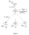
- a caller 402initiates a video call, in one embodiment, by sending a video communication request 403 to a broadcast center 110 or other network node.
- the request 403may be embodied in various forms, depending on the hardware and/or software being used.
- the broadcast center 110Upon receiving the request 403 , the broadcast center 110 identifies the recipient 406 from information contained within the request 403 . In one configuration, the broadcast center 110 extracts an identifier from the request 403 that uniquely identifies the recipient 406 .
- the identifiermay include, for instance, the recipient's name, social security number, e-mail address, and/or personal network address (e.g., ENUM address).
- the identifiermay include the name of the recipient 406 appended by a “.vp” extension, e.g. “Paul_Allen.vp”.
- the broadcast center 110determines a set of communication devices 404 that may be accessible to the recipient 406 .
- Certain communication devices 404may only support audio communication, while others may support both audio and video communication.
- a recipient 406may have access to a personal computer (PC) 404 a at work, a dedicated videophone 404 b at home, and cell phone 404 c on his or her person.
- PCpersonal computer
- other communication devices 404may be associated with a recipient 406 including a home STB 102 (not shown), a home PC (not shown), and the like.
- the broadcast center 110selects the communication device 404 having the highest probability of being presently accessible to the recipient 406 .
- This determinationmay be made using various techniques, embodiments of which are described below. Such techniques are referred to herein as “presence determination.” Of course, those of skill in the art will recognize that numerous other techniques and/or methods may be used within the spirit and scope of the invention.
- login data 405is used to determine which device 404 has the highest probability of being presently accessible to the user.
- Many communication devicessuch as personal computers, ITV systems, and the like, require or permit a user to “log in” or authenticate by means of a user name and password.
- the login processmay be provided for security purposes or merely to facilitate personalization of the device 404 .
- the device 404when a user successfully logs in, notifies the broadcast center 110 .
- the broadcast center 110then maintains a database of login data 405 that may be consulted when a request 403 is received.
- the login data 405includes an indication of the time at which the user logged in, and that the indicated time is relatively recent.
- the login timemay also be used to select the device 404 .
- the device 404 with the most recent login timemay be selected as having the highest probably of being presently accessible to the recipient 406 .
- the broadcast center 110then forwards the video communication request 403 to the selected device 404 (e.g., the office PC 404 a of FIG. 4 ). This may include addressing the request 403 to a unique network address of the selected device 404 .
- the broadcast center 110selects the communication device 404 that is next most likely to be presently accessible to the recipient 406 , and so on.
- the cell phone 404 cmay be determined to be the next most accessible device 404 following the office PC 404 a . Therefore, the broadcast center 110 forwards the video communication request 403 to the cell phone 404 c.
- the broadcast center 110may detect that the selected device 404 , e.g. the cell phone 404 c , supports only audio communication. Accordingly, if the recipient 406 accepts, an audio-only connection between the caller 402 and the recipient 406 is established. If the recipient 406 does not accept within an established time interval, the broadcast center 110 selects another device 404 from the set, and so on, until the recipient 406 accepts, or all the devices 404 have been selected.
- the selected device 404e.g. the cell phone 404 c
- the caller 402may use a single address to establish video communication with a recipient 406 associated with multiple devices 404 , each with a different network address.
- the caller 402need not guess which device 404 is most accessible to the recipient 406 .
- the request 403is automatically forwarded to other devices 404 when the recipient 406 does not answer.
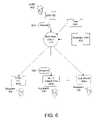
- selection of the most accessible device 404is made with reference to the last device 404 used by the recipient, e.g., “last use” data 502 .
- the last use data 502may indicate that a home videophone 404 b was the last device 404 used by the recipient 406 . Accordingly, the home videophone 404 b may be selected by the broadcast center 110 in one embodiment.
- the broadcast center 110may employ another technique with a higher probability of successfully determining which device 404 is most accessible.
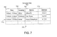
- schedule data 602may be used to select which device 404 has the highest probability of being accessible to the recipient 406 .
- the schedule data 602may indicate which devices 404 the recipient 406 expects to be using at various times and/or the probable physical location of the recipient 406 .
- the schedule data 602may be provided specifically for purposes of presence determination, or may be derived from more general schedule information, such as the a recipient's personal information manager (PIM), e.g., Microsoft Outlook®.
- PIMpersonal information manager
- the schedule data 602may be stored within the broadcast center 110 , or may be obtained by the broadcast center 110 on demand from another computer system or device.
- the schedule data 602may be represented as a table 702 including a number of rows and columns.
- a variety of other data structuresmay be provided within the scope of the invention.
- the table 702may include columns corresponding to a time interval 704 , as well as a physical location 706 and/or a device name 708 or network address 710 .
- Each record 712indicates the recipient's probable physical location 706 and a device 404 expected to be most accessible during the time interval 704 . For example, between 9 am and 5 pm the recipient 406 expects to be at the office. Therefore, a record 712 is added with the 9 am to 5 pm time interval 704 , office location 706 , office PC name 708 , and office PC network address 710 .
- the table 702may only indicate the physical location 706 , in which case another table or data structure (not shown) may be used to correlate physical locations 706 with device names 708 and/or network addresses 710 .
- the device 404is selected using the schedule data 602 and the time 604 the request 403 was received.
- the broadcast center 110searches the schedule data 602 according to the reception time 604 to select the device 404 . For example, suppose a request 403 is received at the broadcast center 110 at 7:32 pm. Accordingly, the probable physical location 706 of the recipient 406 is at home. The broadcast center 110 identifies the home videophone 404 b as the device 404 in closest proximity to the probable physical location 706 of the recipient 406 and selects the home videophone 404 b . Of course the actual physical location of the recipient 406 may not be at home. In such a case, as discussed above, the request 403 may be forwarded to another device 404 within the set.
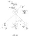
- usage pattern data 802 and an reception time 604are used to select the device 404 most likely to be accessible to the recipient 406 .
- Usage pattern data 802may include a set of machine generated rules concerning video communication habits of the recipient 406 . In certain embodiments, the rules may be viewed and modified by a user.
- Usage pattern data 802may be generated by a broadcast center 110 configured to monitor communications of the recipient 406 using the devices 404 . Of course one or more different devices may monitor communications, generate usage pattern data 802 , and receive communication requests 403 .
- Usage pattern data 802may be generated to reflect historical video communication patterns of a recipient 406 .
- certain historical information from each communicationmay be recorded including the time, date, day of week, call duration, communication device 404 used, and the like.
- the broadcast center 110may then search the historical information for patterns. The search of the historical information may use well known data mining and artificial intelligence (AI) methods.
- AIartificial intelligence
- Table 902illustrates a few example records 904 of rules derived from historical information.
- Each record 904may include a rule number 906 , rule description 908 , and a date 910 on which the rule was generated.
- the table 902may include other columns 912 for storing communication information, such as the device 404 to be selected, and the like.
- the data in the table 902may be in human-readable or non-human-readable form, and may be configured in various different ways within the scope of the invention.
- video communication requests 403are routed to a recipient 406 based on usage pattern data 802 .
- the broadcast center 110accesses the usage pattern data 802 to determine which device 404 to select for forwarding of the request 403 .
- the usage pattern data 802may be stored on an Internet server, database, storage device 310 , or the like.
- the reception time 604may includes the time, date, day of the week, and the like.
- the usage pattern data 802is searched for a rule which most closely represents the time 604 of the received request 403 . Once a rule is found, the request 403 is forwarded to the device 404 indicated by the rule.
- a caller 402may send a video communication request 403 at 6:00 am on Wednesday.
- the request 403is received and the usage pattern data 802 is searched.
- Rule # 3indicates the recipient generally places a video call from the cell phone 404 c on Wednesdays at 6:00 am. Therefore, the request 403 is forwarded to the cell phone 404 c.
- the reception time 604 and user preference data 1002are used to select a device 404 .
- User preference data 1002is information defined primarily by a user (e.g., the recipient 406 ).
- the user preference data 1002indicates a priority for selecting communication devices 404 a - c during general time intervals.
- user preference data 1002may simply designate a priority or order for selecting the devices 404 a - c regardless of the time 604 , e.g. when a first device 404 does not respond, a second device 404 may be selected, etc.
- a table 1102illustrated in FIG. 11 , illustrates an example of user preference data 1002 according to one embodiment.
- the table 1102includes time intervals 704 , device names 708 , and network addresses 710 , similar to those described in relation to FIG. 7 .
- the table 1102also includes a day 1104 column.
- the day 1104may indicate a type of day such as weekday, weekend, holiday, a date range, or the like.
- the table 1102may be configured in various different ways without departing from the spirit and scope of the invention.
- a communication request 403is made at 7:00 pm on Sep. 15, 2001.
- the broadcast center 110identifies, from the user preference data 1002 , the cell phone 404 c as the device to be selected.
- the request 403is then forwarded to the cell phone 404 c.
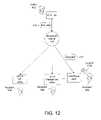
- an alternative embodimentutilizes a locator device 1202 to select a device 404 associated with a recipient 406 based on the recipient's actual presence.
- the locator device 1202may be embodied as any one of a number of devices for monitoring a person's geographic location using, for example, Global Positioning Satellite (GPS) technology, infrared (IR) or radio frequency (RF) technologies, and the like.
- GPSGlobal Positioning Satellite
- IRinfrared
- RFradio frequency
- the broadcast center 110receives requests 403 and monitors the location of the locator device 1202 using well known methods according to the technology of the locator device 1202 .
- the locator device 1202is directly associated with the recipient's person.
- the locator device 1202may be integrated with a watch, ring, or other personal item in close proximity to the recipient 406 .
- the locator device 1202may be integrated with a communication device 404 .
- a cell phone 404 cmay be tracked by the broadcast center 110 moving from cell to cell in a telephone network.
- configuration information identifying each device 404 a - c associated with a recipient 406is stored within the broadcast center 110 .
- the configuration informationmay include a physical location for the device 404 .
- a broadcast center 110may select the device 404 in closest proximity to the recipient's actual physical location, as indicated by the locator device 1202 .
- a communication device 404may automatically send an indication of the recipient's presence to the broadcast center 110 .
- the office PC 404 amay detect a keystroke while the recipient 406 is logged in and send an indication of the recipient's presence to the broadcast center 110 .
- requests 403 received during the time intervalare forwarded to the office PC 404 a .
- the indicationmay be sent according to a format and protocol compatible with the device 404 and the broadcast center 110 .
- the indication of the recipient's presenceis sent in response to a user command.
- the recipient 406may press a specifically designated button on a communication device 404 to cause the indication to be sent to the broadcast center 110 . Accordingly, all requests 403 received after receipt of the indication may be forwarded to the communication device 404 which sent the indication.
- an alternative embodiment for selecting the device 404involves sending a polling signal 1302 to each device 404 within the set of devices 404 to determine the recipient's presence. Each device 404 then determines whether the recipient 406 is using the device 404 (is present) using techniques described above. If a device 404 determines the recipient 406 is present, an indication, such as an acknowledgement signal 1304 , is sent to the broadcast center 110 . In one embodiment, the broadcast center 110 selects the device 404 which sent the acknowledgement signal 1304 .
- Determining whether the recipient 406 is presentmay be accomplished using methods discussed above including measuring time between keystrokes, identifying whether the recipient 406 is logged in, identifying whether the device 404 is currently in use for communication, receiving an input command indicating a recipient's presence, as well as various other methods.
- the broadcast center 110sends a polling signal 1302 to each device 404 a - c .
- the office PC 404 adetects a very short time interval between keystrokes. Therefore, the office PC 404 a responds with an acknowledgement signal 1304 while the other devices 404 b - c send no response. Accordingly, the request 403 is forwarded to the office PC 404 a.
- two devices 404may have the same probability of being accessible to the recipient 406 at the time a request 403 is received. For example, selecting a device 404 using usage pattern data 802 may result in the reception time 604 matching two rules indicating two different devices 404 . In this situation, certain embodiments may determine that a first device 404 , e.g. office PC 404 a , supports audio and video communication and a second device 404 , e.g. cell phone 404 c , supports only audio communication. In response to making this determination, the broadcast center 110 may select the device 404 having more robust communication functionality, e.g. office PC 404 a.
- FIG. 14a system 1400 for routing video calls to a recipient 406 is illustrated.
- the depicted logical componentsmay be implemented using one or more of the physical components shown in FIG. 3 .
- other well known physical components typically used in a broadcast center 110may be used to implement the depicted logical components.
- various logical componentsmay be implemented as software modules stored in the memory 306 and/or storage device 310 and executed by the CPU 312 .
- Those skilled in the artwill recognize that various illustrated components may be combined together or integrated with standard components in various configurations without departing from the scope or spirit of the invention.
- a caller's STB 102may send a video communication request 403 which is received at the broadcast center 110 .
- the system 1400includes a reception component 1402 , which receives the request 403 addressed to the recipient 406 , as described above in connection with FIG. 4 .
- the reception component 1402may be implemented as a software module executing on a CPU 312 in communication with a network interface 302 of the broadcast center 110 .
- the network interface 302monitors incoming packets received from the network 101 .
- a variety of other implementationsare possible.
- the system 1400may also include an identification component 1404 in communication with the reception component 1402 .
- the identification component 1404extracts an address (e.g., an ENUM address) from the request 403 to uniquely identify the recipient 406 , as described in connection with FIG. 4 .
- the addressmay comprise a simple mnemonic to allow for easy memorizing of the address.
- the identification component 1404interacts with a determination component 1406 .
- the determination component 1406determines a set of communication devices 404 associated with the recipient 406 .
- This setmay comprise configuration information stored on a storage device 310 accessible to the broadcast center 110 .
- the configuration information for devices 404 within the setmay be stored in memory 306 at the broadcast center 110 .
- a selection component 1408selects a first device 404 from the set having a highest probability of being accessible to the recipient 406 .
- various selection methods and techniquesmay be used to select the device 404 .
- a storage device 310may be accessed to retrieve information such as last use data 502 , schedule data 602 , usage pattern data 802 , user preference data 1002 , or the like.
- the selection component 1408signals a forwarding component 1410 to forward the request 403 to the selected device 404 a .
- the forwarding component 1410uses configuration information for the selected device 404 a to replace the recipient address with a network address for the device 404 a .
- network addressesneed not be used by the caller 402 .
- a communication component 1412establishes communication between the caller 402 and the recipient 406 .
- the communication component 1412detects that the selected device 404 and the caller's device do not each support the same type of communication.
- the caller's devicee.g., STB 102
- the caller's devicemay support audio and video while the selected device 404 only supports audio.
- the communication component 1412establishes the highest level of communication supported by both devices 102 , 404 , e.g., audio.
- the communication component 1412signals the selection component 1408 to select a second communication device 404 that is next most likely to be presently accessible to the recipient 406 . If the recipient 406 does not accept the request 403 using the second communication device 404 , the forwarding component 1410 and selection component 1408 cooperate to send the request 403 to another device 404 within the set, and so on.
- the method 1500begins by receiving 1502 a request 403 addressed to a recipient 406 .
- the recipient 406is identified 1504 using information within the request 403 .
- a set of communication devices 404 associated with the recipient 406is determined 1506 .
- a first communication device 404 with a highest probability of being accessible to the recipient 406is then selected 1508 from the set.
- the first device 404may be selected according a variety of methods and techniques, as discussed above. Thereafter, the request 403 is forwarded 1510 to the first selected communication device 404 .
- a determination 1512is then made whether the recipient 406 accepts the request 403 within an established time interval. If so, video communication is established 1514 between the caller 402 and the recipient 406 . If not, a second communication device 404 with a next highest probability of being most accessible to a recipient 406 is then selected 1516 . As above, the request 403 is then forwarded 1518 to the second communication device 404 . Thereafter, the method 1500 continues with the determination 1512 step until the recipient accepts the request 403 at the selected device 404 or all the devices 404 within the set have been selected.
- the recipient 406may reject the request 403 at the selected device 404 .
- the request 403may be rejected. Since a rejected request 403 indicates the recipient's presence at the selected device 404 , rejection of the request 403 , like establishing 1514 of video communication, terminates the method 1500 .
- a callermay use a single address to communicate with a recipient associated with multiple communication devices without attempting to contact each device in turn. If the recipient changes physical locations, for example, due to a move, the caller may still use the same address.
- Video callsare routed to a recipient based on a logical determination of a communication device most accessible to the recipient according to usage pattern data, user preference data, a recipient's schedule, a locator device, and the like. In addition, video calls may be routed to a communication device in closest proximity a recipient's actual physical location.
Landscapes
- Engineering & Computer Science (AREA)
- Multimedia (AREA)
- Signal Processing (AREA)
- Telephonic Communication Services (AREA)
Abstract
Description
Claims (34)
Priority Applications (1)
| Application Number | Priority Date | Filing Date | Title |
|---|---|---|---|
| US10/045,672US7243123B1 (en) | 2001-10-22 | 2001-10-22 | Video call routing with presence determination |
Applications Claiming Priority (1)
| Application Number | Priority Date | Filing Date | Title |
|---|---|---|---|
| US10/045,672US7243123B1 (en) | 2001-10-22 | 2001-10-22 | Video call routing with presence determination |
Publications (1)
| Publication Number | Publication Date |
|---|---|
| US7243123B1true US7243123B1 (en) | 2007-07-10 |
Family
ID=38227125
Family Applications (1)
| Application Number | Title | Priority Date | Filing Date |
|---|---|---|---|
| US10/045,672Expired - LifetimeUS7243123B1 (en) | 2001-10-22 | 2001-10-22 | Video call routing with presence determination |
Country Status (1)
| Country | Link |
|---|---|
| US (1) | US7243123B1 (en) |
Cited By (39)
| Publication number | Priority date | Publication date | Assignee | Title |
|---|---|---|---|---|
| US20030233467A1 (en)* | 2002-03-27 | 2003-12-18 | Minolta Co., Ltd. | Data transmission apparatus, data transmission method and data transmission program that can select optimal transmission mode for each recipient |
| US20060239424A1 (en)* | 2005-04-21 | 2006-10-26 | Sbc Knowledge Ventures L.P. | Presence management system |
| US20060253895A1 (en)* | 2005-03-29 | 2006-11-09 | Michael Brandofino | Video communication call authorization |
| US20070002777A1 (en)* | 2005-05-31 | 2007-01-04 | Glowpoint, Inc. | Video-communication interface |
| US20070036086A1 (en)* | 2005-08-09 | 2007-02-15 | Sbc Knowledge Ventures, L.P. | System and method of providing communications based on a predetermined device status |
| US20070042791A1 (en)* | 2005-08-16 | 2007-02-22 | Sbc Knowledge Ventures, L.P. | Presence and availability management over a public communication network |
| US20070060137A1 (en)* | 2005-09-15 | 2007-03-15 | Bellsouth Intellectual Property Corporation | Methods, systems, and computer program products for call/message routing based on determined subscriber activity |
| US20070100940A1 (en)* | 2005-08-25 | 2007-05-03 | Glowpoint, Inc. | Systems and methods for implementing a single-number follow me service for videoconferencing |
| US20080313284A1 (en)* | 2007-06-14 | 2008-12-18 | Qualcomm Incorporated | Wireless device caching data proxy |
| US20090049490A1 (en)* | 2007-08-13 | 2009-02-19 | At&T Knowledge Ventures, L.P. | System for presenting media content |
| US8051447B2 (en) | 2007-12-19 | 2011-11-01 | Verizon Patent And Licensing Inc. | Condensed program guide for media content access systems and methods |
| US8069461B2 (en) | 2006-03-30 | 2011-11-29 | Verizon Services Corp. | On-screen program guide with interactive programming recommendations |
| US8103965B2 (en) | 2007-06-28 | 2012-01-24 | Verizon Patent And Licensing Inc. | Media content recording and healing statuses |
| US20120278462A1 (en)* | 2010-10-29 | 2012-11-01 | Nhn Corporation | Unified communication system and unified communication method using multi-login, terminal for controlling operation of unified communication tool, and communication method in terminal |
| US8418217B2 (en) | 2006-09-06 | 2013-04-09 | Verizon Patent And Licensing Inc. | Systems and methods for accessing media content |
| US8464295B2 (en) | 2006-10-03 | 2013-06-11 | Verizon Patent And Licensing Inc. | Interactive search graphical user interface systems and methods |
| US8510780B2 (en) | 2006-12-21 | 2013-08-13 | Verizon Patent And Licensing Inc. | Program guide navigation tools for media content access systems and methods |
| US20130273896A1 (en)* | 2008-06-25 | 2013-10-17 | Centurylink Intellectual Property Llc | System and method for providing advanced call forwarding functionality |
| US8566874B2 (en) | 2006-10-03 | 2013-10-22 | Verizon Patent And Licensing Inc. | Control tools for media content access systems and methods |
| US8576270B1 (en) | 2004-10-08 | 2013-11-05 | Glowpoint, Inc. | Intelligent call management and redirection |
| US8726159B2 (en) | 2007-01-05 | 2014-05-13 | Verizon Patent And Licensing Inc. | Content level navigation systems and methods |
| US20140208372A1 (en)* | 2007-09-07 | 2014-07-24 | At&T Intellectual Property I, Lp | System for exchanging media content between a media content processor and a communication device |
| US20140267540A1 (en)* | 2013-03-15 | 2014-09-18 | Telmate, Llc | Video communications in detention environments |
| US8874796B1 (en)* | 2006-11-29 | 2014-10-28 | Adtran, Inc. | Techniques for using a general query to circumvent specific query response failure in an IGMP system |
| US8880737B1 (en)* | 2006-11-29 | 2014-11-04 | Adtran, Inc. | Smart immediate leave for internet group management protocol (IGMP) system |
| US8929257B1 (en) | 2013-10-11 | 2015-01-06 | Edifire LLC | Methods and systems for subconferences in secure media-based conferencing |
| WO2015066972A1 (en)* | 2013-11-07 | 2015-05-14 | 深圳创维数字技术股份有限公司 | Video call transfer method, terminal and system |
| US9118654B2 (en) | 2013-10-11 | 2015-08-25 | Edifire LLC | Methods and systems for compliance monitoring in secure media-based conferencing |
| US9118809B2 (en) | 2013-10-11 | 2015-08-25 | Edifire LLC | Methods and systems for multi-factor authentication in secure media-based conferencing |
| US9131112B1 (en) | 2014-09-29 | 2015-09-08 | Edifire LLC | Dynamic signaling and resource allocation in secure media-based conferencing |
| US9137187B1 (en) | 2014-09-29 | 2015-09-15 | Edifire LLC | Dynamic conference session state management in secure media-based conferencing |
| US9167098B1 (en) | 2014-09-29 | 2015-10-20 | Edifire LLC | Dynamic conference session re-routing in secure media-based conferencing |
| US9282130B1 (en) | 2014-09-29 | 2016-03-08 | Edifire LLC | Dynamic media negotiation in secure media-based conferencing |
| US9872155B2 (en) | 2016-02-18 | 2018-01-16 | Vivint, Inc. | Event triggered messaging |
| US10028112B2 (en) | 2016-02-18 | 2018-07-17 | Vivint, Inc. | Event triggered messaging |
| US10433122B1 (en) | 2016-02-18 | 2019-10-01 | Vivint, Inc. | Event triggered messaging |
| US10630844B1 (en)* | 2018-12-19 | 2020-04-21 | T-Mobile Usa, Inc. | Systems and methods for enhanced video call transfer |
| US10771741B1 (en) | 2019-05-31 | 2020-09-08 | International Business Machines Corporation | Adding an individual to a video conference |
| US10791178B1 (en)* | 2017-09-26 | 2020-09-29 | Amazon Technologies, Inc. | Selecting a device for communications session |
Citations (16)
| Publication number | Priority date | Publication date | Assignee | Title |
|---|---|---|---|---|
| US5189691A (en) | 1991-08-30 | 1993-02-23 | Go-Video, Inc. | VCR with video phone answering capability |
| US5896165A (en) | 1997-04-09 | 1999-04-20 | Texas Instruments Incorporated | Method and system for a video answering machine |
| US5937057A (en)* | 1997-03-05 | 1999-08-10 | Selsius Systems, Inc. | Video/audio communications call center and method of operation thereof |
| US6055314A (en)* | 1996-03-22 | 2000-04-25 | Microsoft Corporation | System and method for secure purchase and delivery of video content programs |
| US6092102A (en)* | 1997-10-24 | 2000-07-18 | University Of Pittsburgh Of The Commonwealth System Of Higher Education | System and method for notifying users about information or events of an enterprise |
| US6167122A (en)* | 1996-03-29 | 2000-12-26 | British Telecommunications Public Limited Company | Telecommunications routing based on format of message |
| US6243448B1 (en) | 1996-08-14 | 2001-06-05 | Joseph C. Corbett | Video caller identification systems and methods |
| US6363248B1 (en)* | 1998-12-28 | 2002-03-26 | Lucent Technologies Inc. | Intelligent cellular forwarding system |
| US20020152402A1 (en)* | 2001-02-07 | 2002-10-17 | Tov Ofer Shem | Personalized visitor pages |
| US20030018744A1 (en)* | 2001-02-07 | 2003-01-23 | Johanson James A. | Bluetooth device position display |
| US20030023691A1 (en)* | 2001-07-27 | 2003-01-30 | Knauerhase Robert C. | Routing messages using presence information |
| US20030025787A1 (en)* | 2001-07-31 | 2003-02-06 | Vtel Corporation | System and method for video call configuration and scheduling |
| US6518994B1 (en)* | 1998-01-28 | 2003-02-11 | Ncr Corporation | Video call distribution |
| US20030046705A1 (en)* | 2001-08-28 | 2003-03-06 | Sears Michael E. | System and method for enabling communication between video-enabled and non-video-enabled communication devices |
| US6545697B1 (en)* | 2001-10-16 | 2003-04-08 | Sprint Communications Company, LP | Video telephony |
| US7139722B2 (en)* | 2001-06-27 | 2006-11-21 | Bellsouth Intellectual Property Corporation | Location and time sensitive wireless calendaring |
- 2001
- 2001-10-22USUS10/045,672patent/US7243123B1/ennot_activeExpired - Lifetime
Patent Citations (16)
| Publication number | Priority date | Publication date | Assignee | Title |
|---|---|---|---|---|
| US5189691A (en) | 1991-08-30 | 1993-02-23 | Go-Video, Inc. | VCR with video phone answering capability |
| US6055314A (en)* | 1996-03-22 | 2000-04-25 | Microsoft Corporation | System and method for secure purchase and delivery of video content programs |
| US6167122A (en)* | 1996-03-29 | 2000-12-26 | British Telecommunications Public Limited Company | Telecommunications routing based on format of message |
| US6243448B1 (en) | 1996-08-14 | 2001-06-05 | Joseph C. Corbett | Video caller identification systems and methods |
| US5937057A (en)* | 1997-03-05 | 1999-08-10 | Selsius Systems, Inc. | Video/audio communications call center and method of operation thereof |
| US5896165A (en) | 1997-04-09 | 1999-04-20 | Texas Instruments Incorporated | Method and system for a video answering machine |
| US6092102A (en)* | 1997-10-24 | 2000-07-18 | University Of Pittsburgh Of The Commonwealth System Of Higher Education | System and method for notifying users about information or events of an enterprise |
| US6518994B1 (en)* | 1998-01-28 | 2003-02-11 | Ncr Corporation | Video call distribution |
| US6363248B1 (en)* | 1998-12-28 | 2002-03-26 | Lucent Technologies Inc. | Intelligent cellular forwarding system |
| US20020152402A1 (en)* | 2001-02-07 | 2002-10-17 | Tov Ofer Shem | Personalized visitor pages |
| US20030018744A1 (en)* | 2001-02-07 | 2003-01-23 | Johanson James A. | Bluetooth device position display |
| US7139722B2 (en)* | 2001-06-27 | 2006-11-21 | Bellsouth Intellectual Property Corporation | Location and time sensitive wireless calendaring |
| US20030023691A1 (en)* | 2001-07-27 | 2003-01-30 | Knauerhase Robert C. | Routing messages using presence information |
| US20030025787A1 (en)* | 2001-07-31 | 2003-02-06 | Vtel Corporation | System and method for video call configuration and scheduling |
| US20030046705A1 (en)* | 2001-08-28 | 2003-03-06 | Sears Michael E. | System and method for enabling communication between video-enabled and non-video-enabled communication devices |
| US6545697B1 (en)* | 2001-10-16 | 2003-04-08 | Sprint Communications Company, LP | Video telephony |
Non-Patent Citations (4)
| Title |
|---|
| Bigfoot.com; Bigfoot Email Tools; http://www.bigfoot.com/RUN?FN=forwarding&locale=en...:11123&Cook=&SEQ=&ver=2.0.; printed Jun. 28, 2001. |
| Communicatons Convergence.com; CTI2's Extreme Universal Messaging Platform; http://www.computertelephony.com;article/CTM20000613S0023; printed Jul. 9, 2001. |
| OneName Corporation; XNS Technology; http://www.onename.com/pages/xns<SUB>-</SUB>ov.html; printed Jul. 9, 2001. |
| Teledotcom; Tornado Says Unified Message Is Killer; http://www.teledotcom.com/article/TEL20010620S0003; printed Jul. 9, 2001. |
Cited By (68)
| Publication number | Priority date | Publication date | Assignee | Title |
|---|---|---|---|---|
| US20030233467A1 (en)* | 2002-03-27 | 2003-12-18 | Minolta Co., Ltd. | Data transmission apparatus, data transmission method and data transmission program that can select optimal transmission mode for each recipient |
| US8933983B2 (en) | 2004-10-08 | 2015-01-13 | Glowpoint, Inc. | Intelligent call management and redirection |
| US8576270B1 (en) | 2004-10-08 | 2013-11-05 | Glowpoint, Inc. | Intelligent call management and redirection |
| US20060253895A1 (en)* | 2005-03-29 | 2006-11-09 | Michael Brandofino | Video communication call authorization |
| US20060239424A1 (en)* | 2005-04-21 | 2006-10-26 | Sbc Knowledge Ventures L.P. | Presence management system |
| US8781081B2 (en)* | 2005-04-21 | 2014-07-15 | At&T Intellectual Property I, L.P. | Presence management system |
| US20070002777A1 (en)* | 2005-05-31 | 2007-01-04 | Glowpoint, Inc. | Video-communication interface |
| US20070036086A1 (en)* | 2005-08-09 | 2007-02-15 | Sbc Knowledge Ventures, L.P. | System and method of providing communications based on a predetermined device status |
| US20070042791A1 (en)* | 2005-08-16 | 2007-02-22 | Sbc Knowledge Ventures, L.P. | Presence and availability management over a public communication network |
| US20070100940A1 (en)* | 2005-08-25 | 2007-05-03 | Glowpoint, Inc. | Systems and methods for implementing a single-number follow me service for videoconferencing |
| US20070060137A1 (en)* | 2005-09-15 | 2007-03-15 | Bellsouth Intellectual Property Corporation | Methods, systems, and computer program products for call/message routing based on determined subscriber activity |
| US9084029B2 (en) | 2006-03-30 | 2015-07-14 | Verizon Patent And Licensing Inc. | On-screen program guide with interactive programming recommendations |
| US8677415B2 (en) | 2006-03-30 | 2014-03-18 | Verizon Services Corp. | On-screen program guide with interactive programming recommendations |
| US8069461B2 (en) | 2006-03-30 | 2011-11-29 | Verizon Services Corp. | On-screen program guide with interactive programming recommendations |
| US8881217B2 (en) | 2006-09-06 | 2014-11-04 | Verizon Patent And Licensing Inc. | Systems and methods for accessing media content |
| US8418217B2 (en) | 2006-09-06 | 2013-04-09 | Verizon Patent And Licensing Inc. | Systems and methods for accessing media content |
| US8973040B2 (en) | 2006-10-03 | 2015-03-03 | Verizon Patent And Licensing Inc. | Control tools for media content access systems and methods |
| US8566874B2 (en) | 2006-10-03 | 2013-10-22 | Verizon Patent And Licensing Inc. | Control tools for media content access systems and methods |
| US8464295B2 (en) | 2006-10-03 | 2013-06-11 | Verizon Patent And Licensing Inc. | Interactive search graphical user interface systems and methods |
| US8880737B1 (en)* | 2006-11-29 | 2014-11-04 | Adtran, Inc. | Smart immediate leave for internet group management protocol (IGMP) system |
| US8874796B1 (en)* | 2006-11-29 | 2014-10-28 | Adtran, Inc. | Techniques for using a general query to circumvent specific query response failure in an IGMP system |
| US8510780B2 (en) | 2006-12-21 | 2013-08-13 | Verizon Patent And Licensing Inc. | Program guide navigation tools for media content access systems and methods |
| US8935728B2 (en) | 2006-12-21 | 2015-01-13 | Verizon Patent And Licensing Inc. | Program guide navigation tools for media content access systems and methods |
| US9167190B2 (en) | 2006-12-21 | 2015-10-20 | Verizon Patent And Licensing Inc. | Program guide navigation tools for media content access systems and methods |
| US8726159B2 (en) | 2007-01-05 | 2014-05-13 | Verizon Patent And Licensing Inc. | Content level navigation systems and methods |
| US20080313284A1 (en)* | 2007-06-14 | 2008-12-18 | Qualcomm Incorporated | Wireless device caching data proxy |
| US8787880B2 (en)* | 2007-06-14 | 2014-07-22 | Omnitracs, Llc | Wireless device caching data proxy |
| US8103965B2 (en) | 2007-06-28 | 2012-01-24 | Verizon Patent And Licensing Inc. | Media content recording and healing statuses |
| US9100711B2 (en) | 2007-08-13 | 2015-08-04 | At&T Intellectual Property I, Lp | System for presenting media content |
| US8739224B2 (en) | 2007-08-13 | 2014-05-27 | At&T Intellectual Property I, Lp | System for presenting media content |
| US8484685B2 (en)* | 2007-08-13 | 2013-07-09 | At&T Intellectual Property I, L.P. | System for presenting media content |
| US9942613B2 (en) | 2007-08-13 | 2018-04-10 | At&T Intellectual Property I, L.P. | System for presenting media content |
| US10939177B2 (en) | 2007-08-13 | 2021-03-02 | At&T Intellectual Property I, L.P. | System for presenting media content |
| US20090049490A1 (en)* | 2007-08-13 | 2009-02-19 | At&T Knowledge Ventures, L.P. | System for presenting media content |
| US20160373791A1 (en)* | 2007-09-07 | 2016-12-22 | At&T Intellectual Property I, L.P. | System for Exchanging Media Content Between a Media Content Processor and a Communication Device |
| US20140208372A1 (en)* | 2007-09-07 | 2014-07-24 | At&T Intellectual Property I, Lp | System for exchanging media content between a media content processor and a communication device |
| US11197041B2 (en)* | 2007-09-07 | 2021-12-07 | At&T Intellectual Property I, L.P. | System for exchanging media content between a media content processor and a communication device |
| US20190158891A1 (en)* | 2007-09-07 | 2019-05-23 | At&T Intellectual Property I, L.P. | System for Exchanging Media Content Between a Media Content Processor and a Communication Device |
| US10200726B2 (en)* | 2007-09-07 | 2019-02-05 | At&T Intellectual Property I, L.P. | System for exchanging media content between a media content processor and a communication device |
| US9462310B2 (en)* | 2007-09-07 | 2016-10-04 | At&T Intellectual Property I, Lp | System for exchanging media content between a media content processor and a communication device |
| US8051447B2 (en) | 2007-12-19 | 2011-11-01 | Verizon Patent And Licensing Inc. | Condensed program guide for media content access systems and methods |
| US10222934B2 (en) | 2007-12-19 | 2019-03-05 | Verizon Patent And Licensing Inc. | Condensed program guide for media content access systems and methods |
| US20130273896A1 (en)* | 2008-06-25 | 2013-10-17 | Centurylink Intellectual Property Llc | System and method for providing advanced call forwarding functionality |
| US9036803B2 (en)* | 2008-06-25 | 2015-05-19 | Centurylink Intellectual Property Llc | System and method for providing advanced call forwarding functionality |
| US9659337B2 (en)* | 2010-10-29 | 2017-05-23 | Nhn Corporation | Unified communication system and unified communication method using multi-login, terminal for controlling operation of unified communication tool, and communication method in terminal |
| US20120278462A1 (en)* | 2010-10-29 | 2012-11-01 | Nhn Corporation | Unified communication system and unified communication method using multi-login, terminal for controlling operation of unified communication tool, and communication method in terminal |
| US20140267540A1 (en)* | 2013-03-15 | 2014-09-18 | Telmate, Llc | Video communications in detention environments |
| US9948886B2 (en) | 2013-03-15 | 2018-04-17 | Intelmate Llc | Video communications in detention environments |
| US9225935B2 (en)* | 2013-03-15 | 2015-12-29 | Intelmate Llc | Video communications in detention environments |
| US9338285B2 (en) | 2013-10-11 | 2016-05-10 | Edifire LLC | Methods and systems for multi-factor authentication in secure media-based conferencing |
| US8929257B1 (en) | 2013-10-11 | 2015-01-06 | Edifire LLC | Methods and systems for subconferences in secure media-based conferencing |
| US8970660B1 (en) | 2013-10-11 | 2015-03-03 | Edifire LLC | Methods and systems for authentication in secure media-based conferencing |
| US8970659B1 (en) | 2013-10-11 | 2015-03-03 | Edifire LLC | Methods and systems for secure media-based conferencing |
| US9118654B2 (en) | 2013-10-11 | 2015-08-25 | Edifire LLC | Methods and systems for compliance monitoring in secure media-based conferencing |
| US9118809B2 (en) | 2013-10-11 | 2015-08-25 | Edifire LLC | Methods and systems for multi-factor authentication in secure media-based conferencing |
| WO2015066972A1 (en)* | 2013-11-07 | 2015-05-14 | 深圳创维数字技术股份有限公司 | Video call transfer method, terminal and system |
| US9282130B1 (en) | 2014-09-29 | 2016-03-08 | Edifire LLC | Dynamic media negotiation in secure media-based conferencing |
| US9167098B1 (en) | 2014-09-29 | 2015-10-20 | Edifire LLC | Dynamic conference session re-routing in secure media-based conferencing |
| US9137187B1 (en) | 2014-09-29 | 2015-09-15 | Edifire LLC | Dynamic conference session state management in secure media-based conferencing |
| US9131112B1 (en) | 2014-09-29 | 2015-09-08 | Edifire LLC | Dynamic signaling and resource allocation in secure media-based conferencing |
| US10028112B2 (en) | 2016-02-18 | 2018-07-17 | Vivint, Inc. | Event triggered messaging |
| US10433122B1 (en) | 2016-02-18 | 2019-10-01 | Vivint, Inc. | Event triggered messaging |
| US9872155B2 (en) | 2016-02-18 | 2018-01-16 | Vivint, Inc. | Event triggered messaging |
| US10791178B1 (en)* | 2017-09-26 | 2020-09-29 | Amazon Technologies, Inc. | Selecting a device for communications session |
| US10630844B1 (en)* | 2018-12-19 | 2020-04-21 | T-Mobile Usa, Inc. | Systems and methods for enhanced video call transfer |
| US11012576B2 (en) | 2018-12-19 | 2021-05-18 | T-Mobile Usa, Inc. | Systems and methods for enhanced video call transfer |
| US10771741B1 (en) | 2019-05-31 | 2020-09-08 | International Business Machines Corporation | Adding an individual to a video conference |
| US10771740B1 (en) | 2019-05-31 | 2020-09-08 | International Business Machines Corporation | Adding an individual to a video conference |
Similar Documents
| Publication | Publication Date | Title |
|---|---|---|
| US7243123B1 (en) | Video call routing with presence determination | |
| US7006613B2 (en) | System and method for screening incoming video communications within an interactive television system | |
| US9819989B2 (en) | Remote control device signal distribution | |
| US9621943B2 (en) | Multimedia processing resource with interactive voice response | |
| US7142230B2 (en) | System and method for screening incoming and outgoing video communications within an interactive television system | |
| US9015782B2 (en) | Signal distribution system with interrupt processing and trick play functionality | |
| US7003795B2 (en) | Webcam-based interface for initiating two-way video communication | |
| US20030041333A1 (en) | System and method for automatically answering and recording video calls | |
| US20030041332A1 (en) | System and method for mitigating interruptions during television viewing | |
| US6941575B2 (en) | Webcam-based interface for initiating two-way video communication and providing access to cached video | |
| EP2398237B1 (en) | Display apparatus and method for connecting to video call thereof | |
| US20020054206A1 (en) | Systems and devices for audio and video capture and communication during television broadcasts | |
| US20020149705A1 (en) | Contact list for a hybrid communicator/remote control | |
| US9843765B2 (en) | Integrated devices for multimedia content delivery and video conferencing | |
| US20030046705A1 (en) | System and method for enabling communication between video-enabled and non-video-enabled communication devices | |
| US20100161801A1 (en) | Multimedia processing resource with distributed settings | |
| US8612456B2 (en) | Scheduling recording of recommended multimedia programs | |
| US20030041331A1 (en) | System and method for mitigating interruptions during television viewing | |
| WO2003019945A1 (en) | System and method for mitigating interruptions during television viewing | |
| US20090080624A1 (en) | System and Method for Rules-Based Caller ID Notification | |
| WO2003021960A1 (en) | Tv system with group communication | |
| KR20050037252A (en) | Method and apparatus of offer broadcasting service using wireless lan | |
| WO2003003708A2 (en) | Webcam-based interface for initiating two-way video communication |
Legal Events
| Date | Code | Title | Description |
|---|---|---|---|
| AS | Assignment | Owner name:DIGEO, INC., WASHINGTON Free format text:ASSIGNMENT OF ASSIGNORS INTEREST;ASSIGNORS:ALLEN, PAUL G.;BILLMAIER, JAMES A.;BOYDEN, JAMES H.;AND OTHERS;REEL/FRAME:012970/0689;SIGNING DATES FROM 20011109 TO 20020603 | |
| STCF | Information on status: patent grant | Free format text:PATENTED CASE | |
| AS | Assignment | Owner name:VULCAN VENTURES, INC., WASHINGTON Free format text:ASSIGNMENT OF ASSIGNORS INTEREST;ASSIGNOR:DIGEO, INC.;REEL/FRAME:022309/0016 Effective date:20090220 Owner name:VULCAN VENTURES, INC.,WASHINGTON Free format text:ASSIGNMENT OF ASSIGNORS INTEREST;ASSIGNOR:DIGEO, INC.;REEL/FRAME:022309/0016 Effective date:20090220 | |
| FPAY | Fee payment | Year of fee payment:4 | |
| AS | Assignment | Owner name:ARRIS GROUP, INC., GEORGIA Free format text:ASSIGNMENT OF ASSIGNORS INTEREST;ASSIGNOR:DIGEO, INC AND VULCAN VENTURES, INC.;REEL/FRAME:026621/0258 Effective date:20090922 | |
| AS | Assignment | Owner name:ARRIS ENTERPRISES, INC., GEORGIA Free format text:MERGER;ASSIGNOR:ARRIS GROUP, INC.;REEL/FRAME:030228/0330 Effective date:20130416 | |
| AS | Assignment | Owner name:BANK OF AMERICA, N.A., AS ADMINISTRATIVE AGENT, IL Free format text:SECURITY AGREEMENT;ASSIGNORS:ARRIS GROUP, INC.;ARRIS ENTERPRISES, INC.;ARRIS SOLUTIONS, INC.;AND OTHERS;REEL/FRAME:030498/0023 Effective date:20130417 Owner name:BANK OF AMERICA, N.A., AS ADMINISTRATIVE AGENT, ILLINOIS Free format text:SECURITY AGREEMENT;ASSIGNORS:ARRIS GROUP, INC.;ARRIS ENTERPRISES, INC.;ARRIS SOLUTIONS, INC.;AND OTHERS;REEL/FRAME:030498/0023 Effective date:20130417 | |
| FPAY | Fee payment | Year of fee payment:8 | |
| AS | Assignment | Owner name:ARRIS ENTERPRISES LLC, PENNSYLVANIA Free format text:CHANGE OF NAME;ASSIGNOR:ARRIS ENTERPRISES INC;REEL/FRAME:041995/0031 Effective date:20151231 | |
| MAFP | Maintenance fee payment | Free format text:PAYMENT OF MAINTENANCE FEE, 12TH YEAR, LARGE ENTITY (ORIGINAL EVENT CODE: M1553); ENTITY STATUS OF PATENT OWNER: LARGE ENTITY Year of fee payment:12 | |
| AS | Assignment | Owner name:NEXTLEVEL SYSTEMS (PUERTO RICO), INC., PENNSYLVANI Free format text:TERMINATION AND RELEASE OF SECURITY INTEREST IN PATENTS;ASSIGNOR:BANK OF AMERICA, N.A., AS ADMINISTRATIVE AGENT;REEL/FRAME:048825/0294 Effective date:20190404 Owner name:JERROLD DC RADIO, INC., PENNSYLVANIA Free format text:TERMINATION AND RELEASE OF SECURITY INTEREST IN PATENTS;ASSIGNOR:BANK OF AMERICA, N.A., AS ADMINISTRATIVE AGENT;REEL/FRAME:048825/0294 Effective date:20190404 Owner name:GIC INTERNATIONAL CAPITAL LLC, PENNSYLVANIA Free format text:TERMINATION AND RELEASE OF SECURITY INTEREST IN PATENTS;ASSIGNOR:BANK OF AMERICA, N.A., AS ADMINISTRATIVE AGENT;REEL/FRAME:048825/0294 Effective date:20190404 Owner name:GENERAL INSTRUMENT CORPORATION, PENNSYLVANIA Free format text:TERMINATION AND RELEASE OF SECURITY INTEREST IN PATENTS;ASSIGNOR:BANK OF AMERICA, N.A., AS ADMINISTRATIVE AGENT;REEL/FRAME:048825/0294 Effective date:20190404 Owner name:ARRIS HOLDINGS CORP. OF ILLINOIS, INC., PENNSYLVAN Free format text:TERMINATION AND RELEASE OF SECURITY INTEREST IN PATENTS;ASSIGNOR:BANK OF AMERICA, N.A., AS ADMINISTRATIVE AGENT;REEL/FRAME:048825/0294 Effective date:20190404 Owner name:AEROCAST, INC., PENNSYLVANIA Free format text:TERMINATION AND RELEASE OF SECURITY INTEREST IN PATENTS;ASSIGNOR:BANK OF AMERICA, N.A., AS ADMINISTRATIVE AGENT;REEL/FRAME:048825/0294 Effective date:20190404 Owner name:POWER GUARD, INC., PENNSYLVANIA Free format text:TERMINATION AND RELEASE OF SECURITY INTEREST IN PATENTS;ASSIGNOR:BANK OF AMERICA, N.A., AS ADMINISTRATIVE AGENT;REEL/FRAME:048825/0294 Effective date:20190404 Owner name:NETOPIA, INC., PENNSYLVANIA Free format text:TERMINATION AND RELEASE OF SECURITY INTEREST IN PATENTS;ASSIGNOR:BANK OF AMERICA, N.A., AS ADMINISTRATIVE AGENT;REEL/FRAME:048825/0294 Effective date:20190404 Owner name:GIC INTERNATIONAL HOLDCO LLC, PENNSYLVANIA Free format text:TERMINATION AND RELEASE OF SECURITY INTEREST IN PATENTS;ASSIGNOR:BANK OF AMERICA, N.A., AS ADMINISTRATIVE AGENT;REEL/FRAME:048825/0294 Effective date:20190404 Owner name:LEAPSTONE SYSTEMS, INC., PENNSYLVANIA Free format text:TERMINATION AND RELEASE OF SECURITY INTEREST IN PATENTS;ASSIGNOR:BANK OF AMERICA, N.A., AS ADMINISTRATIVE AGENT;REEL/FRAME:048825/0294 Effective date:20190404 Owner name:SETJAM, INC., PENNSYLVANIA Free format text:TERMINATION AND RELEASE OF SECURITY INTEREST IN PATENTS;ASSIGNOR:BANK OF AMERICA, N.A., AS ADMINISTRATIVE AGENT;REEL/FRAME:048825/0294 Effective date:20190404 Owner name:ARRIS SOLUTIONS, INC., PENNSYLVANIA Free format text:TERMINATION AND RELEASE OF SECURITY INTEREST IN PATENTS;ASSIGNOR:BANK OF AMERICA, N.A., AS ADMINISTRATIVE AGENT;REEL/FRAME:048825/0294 Effective date:20190404 Owner name:4HOME, INC., PENNSYLVANIA Free format text:TERMINATION AND RELEASE OF SECURITY INTEREST IN PATENTS;ASSIGNOR:BANK OF AMERICA, N.A., AS ADMINISTRATIVE AGENT;REEL/FRAME:048825/0294 Effective date:20190404 Owner name:BIG BAND NETWORKS, INC., PENNSYLVANIA Free format text:TERMINATION AND RELEASE OF SECURITY INTEREST IN PATENTS;ASSIGNOR:BANK OF AMERICA, N.A., AS ADMINISTRATIVE AGENT;REEL/FRAME:048825/0294 Effective date:20190404 Owner name:THE GI REALTY TRUST 1996, PENNSYLVANIA Free format text:TERMINATION AND RELEASE OF SECURITY INTEREST IN PATENTS;ASSIGNOR:BANK OF AMERICA, N.A., AS ADMINISTRATIVE AGENT;REEL/FRAME:048825/0294 Effective date:20190404 Owner name:MOTOROLA WIRELINE NETWORKS, INC., PENNSYLVANIA Free format text:TERMINATION AND RELEASE OF SECURITY INTEREST IN PATENTS;ASSIGNOR:BANK OF AMERICA, N.A., AS ADMINISTRATIVE AGENT;REEL/FRAME:048825/0294 Effective date:20190404 Owner name:ARRIS ENTERPRISES, INC., PENNSYLVANIA Free format text:TERMINATION AND RELEASE OF SECURITY INTEREST IN PATENTS;ASSIGNOR:BANK OF AMERICA, N.A., AS ADMINISTRATIVE AGENT;REEL/FRAME:048825/0294 Effective date:20190404 Owner name:IMEDIA CORPORATION, PENNSYLVANIA Free format text:TERMINATION AND RELEASE OF SECURITY INTEREST IN PATENTS;ASSIGNOR:BANK OF AMERICA, N.A., AS ADMINISTRATIVE AGENT;REEL/FRAME:048825/0294 Effective date:20190404 Owner name:SUNUP DESIGN SYSTEMS, INC., PENNSYLVANIA Free format text:TERMINATION AND RELEASE OF SECURITY INTEREST IN PATENTS;ASSIGNOR:BANK OF AMERICA, N.A., AS ADMINISTRATIVE AGENT;REEL/FRAME:048825/0294 Effective date:20190404 Owner name:BROADBUS TECHNOLOGIES, INC., PENNSYLVANIA Free format text:TERMINATION AND RELEASE OF SECURITY INTEREST IN PATENTS;ASSIGNOR:BANK OF AMERICA, N.A., AS ADMINISTRATIVE AGENT;REEL/FRAME:048825/0294 Effective date:20190404 Owner name:MODULUS VIDEO, INC., PENNSYLVANIA Free format text:TERMINATION AND RELEASE OF SECURITY INTEREST IN PATENTS;ASSIGNOR:BANK OF AMERICA, N.A., AS ADMINISTRATIVE AGENT;REEL/FRAME:048825/0294 Effective date:20190404 Owner name:GENERAL INSTRUMENT AUTHORIZATION SERVICES, INC., P Free format text:TERMINATION AND RELEASE OF SECURITY INTEREST IN PATENTS;ASSIGNOR:BANK OF AMERICA, N.A., AS ADMINISTRATIVE AGENT;REEL/FRAME:048825/0294 Effective date:20190404 Owner name:ARRIS GROUP, INC., PENNSYLVANIA Free format text:TERMINATION AND RELEASE OF SECURITY INTEREST IN PATENTS;ASSIGNOR:BANK OF AMERICA, N.A., AS ADMINISTRATIVE AGENT;REEL/FRAME:048825/0294 Effective date:20190404 Owner name:CCE SOFTWARE LLC, PENNSYLVANIA Free format text:TERMINATION AND RELEASE OF SECURITY INTEREST IN PATENTS;ASSIGNOR:BANK OF AMERICA, N.A., AS ADMINISTRATIVE AGENT;REEL/FRAME:048825/0294 Effective date:20190404 Owner name:ARRIS KOREA, INC., PENNSYLVANIA Free format text:TERMINATION AND RELEASE OF SECURITY INTEREST IN PATENTS;ASSIGNOR:BANK OF AMERICA, N.A., AS ADMINISTRATIVE AGENT;REEL/FRAME:048825/0294 Effective date:20190404 Owner name:TEXSCAN CORPORATION, PENNSYLVANIA Free format text:TERMINATION AND RELEASE OF SECURITY INTEREST IN PATENTS;ASSIGNOR:BANK OF AMERICA, N.A., AS ADMINISTRATIVE AGENT;REEL/FRAME:048825/0294 Effective date:20190404 Owner name:UCENTRIC SYSTEMS, INC., PENNSYLVANIA Free format text:TERMINATION AND RELEASE OF SECURITY INTEREST IN PATENTS;ASSIGNOR:BANK OF AMERICA, N.A., AS ADMINISTRATIVE AGENT;REEL/FRAME:048825/0294 Effective date:20190404 Owner name:ACADIA AIC, INC., PENNSYLVANIA Free format text:TERMINATION AND RELEASE OF SECURITY INTEREST IN PATENTS;ASSIGNOR:BANK OF AMERICA, N.A., AS ADMINISTRATIVE AGENT;REEL/FRAME:048825/0294 Effective date:20190404 Owner name:QUANTUM BRIDGE COMMUNICATIONS, INC., PENNSYLVANIA Free format text:TERMINATION AND RELEASE OF SECURITY INTEREST IN PATENTS;ASSIGNOR:BANK OF AMERICA, N.A., AS ADMINISTRATIVE AGENT;REEL/FRAME:048825/0294 Effective date:20190404 Owner name:GENERAL INSTRUMENT INTERNATIONAL HOLDINGS, INC., P Free format text:TERMINATION AND RELEASE OF SECURITY INTEREST IN PATENTS;ASSIGNOR:BANK OF AMERICA, N.A., AS ADMINISTRATIVE AGENT;REEL/FRAME:048825/0294 Effective date:20190404 Owner name:ARRIS HOLDINGS CORP. OF ILLINOIS, INC., PENNSYLVANIA Free format text:TERMINATION AND RELEASE OF SECURITY INTEREST IN PATENTS;ASSIGNOR:BANK OF AMERICA, N.A., AS ADMINISTRATIVE AGENT;REEL/FRAME:048825/0294 Effective date:20190404 Owner name:NEXTLEVEL SYSTEMS (PUERTO RICO), INC., PENNSYLVANIA Free format text:TERMINATION AND RELEASE OF SECURITY INTEREST IN PATENTS;ASSIGNOR:BANK OF AMERICA, N.A., AS ADMINISTRATIVE AGENT;REEL/FRAME:048825/0294 Effective date:20190404 Owner name:GENERAL INSTRUMENT INTERNATIONAL HOLDINGS, INC., PENNSYLVANIA Free format text:TERMINATION AND RELEASE OF SECURITY INTEREST IN PATENTS;ASSIGNOR:BANK OF AMERICA, N.A., AS ADMINISTRATIVE AGENT;REEL/FRAME:048825/0294 Effective date:20190404 Owner name:GENERAL INSTRUMENT AUTHORIZATION SERVICES, INC., PENNSYLVANIA Free format text:TERMINATION AND RELEASE OF SECURITY INTEREST IN PATENTS;ASSIGNOR:BANK OF AMERICA, N.A., AS ADMINISTRATIVE AGENT;REEL/FRAME:048825/0294 Effective date:20190404 | |
| AS | Assignment | Owner name:ARRIS ENTERPRISES LLC, GEORGIA Free format text:CHANGE OF NAME;ASSIGNOR:ARRIS ENTERPRISES, INC.;REEL/FRAME:049586/0470 Effective date:20151231 | |
| AS | Assignment | Owner name:WILMINGTON TRUST, NATIONAL ASSOCIATION, AS COLLATE Free format text:PATENT SECURITY AGREEMENT;ASSIGNOR:ARRIS ENTERPRISES LLC;REEL/FRAME:049820/0495 Effective date:20190404 Owner name:JPMORGAN CHASE BANK, N.A., NEW YORK Free format text:ABL SECURITY AGREEMENT;ASSIGNORS:COMMSCOPE, INC. OF NORTH CAROLINA;COMMSCOPE TECHNOLOGIES LLC;ARRIS ENTERPRISES LLC;AND OTHERS;REEL/FRAME:049892/0396 Effective date:20190404 Owner name:JPMORGAN CHASE BANK, N.A., NEW YORK Free format text:TERM LOAN SECURITY AGREEMENT;ASSIGNORS:COMMSCOPE, INC. OF NORTH CAROLINA;COMMSCOPE TECHNOLOGIES LLC;ARRIS ENTERPRISES LLC;AND OTHERS;REEL/FRAME:049905/0504 Effective date:20190404 Owner name:WILMINGTON TRUST, NATIONAL ASSOCIATION, AS COLLATERAL AGENT, CONNECTICUT Free format text:PATENT SECURITY AGREEMENT;ASSIGNOR:ARRIS ENTERPRISES LLC;REEL/FRAME:049820/0495 Effective date:20190404 | |
| AS | Assignment | Owner name:WILMINGTON TRUST, DELAWARE Free format text:SECURITY INTEREST;ASSIGNORS:ARRIS SOLUTIONS, INC.;ARRIS ENTERPRISES LLC;COMMSCOPE TECHNOLOGIES LLC;AND OTHERS;REEL/FRAME:060752/0001 Effective date:20211115 | |
| AS | Assignment | Owner name:RUCKUS WIRELESS, LLC (F/K/A RUCKUS WIRELESS, INC.), NORTH CAROLINA Free format text:RELEASE OF SECURITY INTEREST AT REEL/FRAME 049905/0504;ASSIGNOR:JPMORGAN CHASE BANK, N.A., AS COLLATERAL AGENT;REEL/FRAME:071477/0255 Effective date:20241217 Owner name:COMMSCOPE TECHNOLOGIES LLC, NORTH CAROLINA Free format text:RELEASE OF SECURITY INTEREST AT REEL/FRAME 049905/0504;ASSIGNOR:JPMORGAN CHASE BANK, N.A., AS COLLATERAL AGENT;REEL/FRAME:071477/0255 Effective date:20241217 Owner name:COMMSCOPE, INC. OF NORTH CAROLINA, NORTH CAROLINA Free format text:RELEASE OF SECURITY INTEREST AT REEL/FRAME 049905/0504;ASSIGNOR:JPMORGAN CHASE BANK, N.A., AS COLLATERAL AGENT;REEL/FRAME:071477/0255 Effective date:20241217 Owner name:ARRIS SOLUTIONS, INC., NORTH CAROLINA Free format text:RELEASE OF SECURITY INTEREST AT REEL/FRAME 049905/0504;ASSIGNOR:JPMORGAN CHASE BANK, N.A., AS COLLATERAL AGENT;REEL/FRAME:071477/0255 Effective date:20241217 Owner name:ARRIS TECHNOLOGY, INC., NORTH CAROLINA Free format text:RELEASE OF SECURITY INTEREST AT REEL/FRAME 049905/0504;ASSIGNOR:JPMORGAN CHASE BANK, N.A., AS COLLATERAL AGENT;REEL/FRAME:071477/0255 Effective date:20241217 Owner name:ARRIS ENTERPRISES LLC (F/K/A ARRIS ENTERPRISES, INC.), NORTH CAROLINA Free format text:RELEASE OF SECURITY INTEREST AT REEL/FRAME 049905/0504;ASSIGNOR:JPMORGAN CHASE BANK, N.A., AS COLLATERAL AGENT;REEL/FRAME:071477/0255 Effective date:20241217 |