US7242933B1 - Relocation in a communication system - Google Patents
Relocation in a communication systemDownload PDFInfo
- Publication number
- US7242933B1 US7242933B1US10/088,452US8845200AUS7242933B1US 7242933 B1US7242933 B1US 7242933B1US 8845200 AUS8845200 AUS 8845200AUS 7242933 B1US7242933 B1US 7242933B1
- Authority
- US
- United States
- Prior art keywords
- protocol
- termination point
- radio interface
- initialization unit
- network element
- Prior art date
- Legal status (The legal status is an assumption and is not a legal conclusion. Google has not performed a legal analysis and makes no representation as to the accuracy of the status listed.)
- Expired - Lifetime, expires
Links
- 238000004891communicationMethods0.000titleclaimsabstractdescription49
- 238000000034methodMethods0.000claimsdescription27
- 230000005540biological transmissionEffects0.000claimsdescription7
- 230000004044responseEffects0.000claimsdescription5
- 230000010267cellular communicationEffects0.000claimsdescription4
- 230000001413cellular effectEffects0.000description6
- 230000011664signalingEffects0.000description4
- 230000008901benefitEffects0.000description3
- 230000008859changeEffects0.000description3
- 238000010586diagramMethods0.000description2
- 238000005457optimizationMethods0.000description2
- 108700026140MAC combinationProteins0.000description1
- 230000001419dependent effectEffects0.000description1
- 238000005538encapsulationMethods0.000description1
- 238000005286illuminationMethods0.000description1
- 230000006872improvementEffects0.000description1
- 230000000977initiatory effectEffects0.000description1
- 238000012423maintenanceMethods0.000description1
- 238000005259measurementMethods0.000description1
- 238000012986modificationMethods0.000description1
- 230000004048modificationEffects0.000description1
- 230000008569processEffects0.000description1
- 230000001960triggered effectEffects0.000description1
Images


Classifications
- H—ELECTRICITY
- H04—ELECTRIC COMMUNICATION TECHNIQUE
- H04W—WIRELESS COMMUNICATION NETWORKS
- H04W36/00—Hand-off or reselection arrangements
- H04W36/16—Performing reselection for specific purposes
- H04W36/22—Performing reselection for specific purposes for handling the traffic
- H—ELECTRICITY
- H04—ELECTRIC COMMUNICATION TECHNIQUE
- H04W—WIRELESS COMMUNICATION NETWORKS
- H04W36/00—Hand-off or reselection arrangements
- H04W36/12—Reselecting a serving backbone network switching or routing node
- H04W36/125—Reselecting a serving backbone network switching or routing node involving different types of service backbones
Definitions
- the present inventionrelates to relocation in a communication system and in particular, but not exclusively, to relocation of a protocol termination point.
- Communication networkstypically operate in accordance with a given standard which sets out what the elements of the network are permitted to do and how that should be achieved.
- the communication in the networksfollows predefined rules which are referred to in the following as protocols.
- the protocols to be usedare defined in the associated standard.
- the protocolscan be used for controlling various events and functionalities in a connection provided through the communications network.
- Several protocolsmay be simultaneously in an active state for providing control of a connection.
- a protocolis having a termination point in the network element controlling the connection.
- a protocolmay have termination points in a telephone terminal and in a network controller controlling the connection.
- a communication networkis a cellular radio network consisting of cells.
- the cellcan be defined as a certain area covered by one or several base transceiver stations (BTS) serving mobile stations (MS) via a radio interface and connected to a base station subsystem (BSS).
- BTSbase transceiver stations
- MSmobile stations
- BSSbase station subsystem
- Several cellscover a larger area, and form the coverage area of a cellular radio network.
- the cell (or group of cells) and thus the mobile station (MS) or similar user equipment (UE) within one of the cells of the systemcan be controlled by a node providing controller functionality, for example by a radio network controller (RNC) or a mobile switching center (MSC).
- RNCradio network controller
- MSCmobile switching center
- the controllercan be connected further to a gateway or linking node, for example a gateway GPRS support node (GGSN) or gateway mobile switching center (GSMC), linking the cell to the other parts of the communication system and/or other communication networks, such as to a PSTN (Public Switched Telecommunications Network) or to a data network, such as to a X.25 based network or to a TCP/IP (Transmission Control Protocol/Internet Protocol) based network.
- GGSNgateway GPRS support node
- GSMCgateway mobile switching center
- the mobile station MSmay be controlled by only one controller at time. However, the MS may also be simultaneously controlled by several controller nodes. This may occur e.g. when the cells overlap or in so called soft handoff mode, where the MS may be in communication with two base stations and those base stations may be connected to different controllers, or when one controller is controlling another controller controlling the MS.
- One controller of the plurality of controllers in the systemcan be defined as a serving (main) controller whereas the others may act as secondary controllers.
- the responsibility of controlling a connection between the mobile station and the networkmay change during an ongoing connection. It is therefore necessary to relocate at least part of functionalities associated with the connection such that the connection will not become disconnected and/or that the quality of the connection remains in an acceptable level. It is to be appreciated that in addition or as an alternative to relocating functionalities of the controller node, the functionality to be relocated may also be located in any other of the network elements, for example in the base station, base station subsystem, in the gateway and so on.
- the serving controller or another node of the communication systemmay initiate the necessary proceeding for replacing one or several of the network nodes with a new corresponding node or nodes.
- one of the features that should be relocatedis the state of a protocol termination point.
- the status of the protocol termination point at the new “replacing” network element or nodeshould be such that it may take over the functions of the old “replaced” network node.
- the parameters which need to be transferredhave to be defined also in the protocols which are used to convey the information from the old termination point to the new termination point.
- RRCRadio Resource Control
- MACMedium Access Control
- RLCRadio Link Control
- a method in a communication system for relocating a protocol termination pointcomprising:
- a communication systemcomprising:
- control meansfor relocating a first protocol from the first protocol termination point to the second protocol termination point, said control means being arranged to form a protocol initialization unit containing predefined information of the first protocol at the first protocol termination point;
- control meansfor initializing the second protocol termination point based on the protocol initialization unit.
- a network element for use in a communication networkcomprising:
- control meansfor relocating a first protocol from the protocol termination point to another protocol termination point, said control means being arranged to form a protocol initialization unit containing predefined information of the first protocol at the protocol termination point;
- a network element for use in a communication networkcomprising:
- control meansfor initializing the protocol termination point based on the received protocol initialization unit.
- the protocol initialization unitmay contain state information of the first protocol termination point.
- the first termination pointmay also be located at a first network element of the communication system and the second termination point may be located at a second network element of the communication system.
- the second network elementmay, upon receiving the protocol information unit, generate and transmit a response to the first network element by means of the second protocol.
- the protocol initialization unitmay be encapsulated in a message transmitted between the first termination point and the second termination point.
- the protocol initialization unitmay also be transparent for the second protocol.
- the protocol initialization unitmay be transmitted via a network element of a core network of the communication system.
- the protocol initialization unitmay be transmitted directly between the termination points. This may be accomplished by means of a radio network subsystem application part (RNSAP) protocol.
- RNSAPradio network subsystem application part
- the protocol initialization unitmay contain information of at least one further protocol. According to an embodiment at least one further protocol initialization unit may be defined containing predefined information of a further protocol by the further protocol, whereafter the further protocol initialization unit is transferred from the first termination point to the second termination point. The further protocol initialization unit may be transferred between the termination points by a protocol that is different to the second protocol.
- the parameters of the second termination pointmay be set into a state that is relatively similar to the state of parameters of the first termination point before or at the time the relocation procedure was initiated during the initialization procedure.
- the embodiments of the inventionprovide several advantages.
- One of the benefitsis that a need for defining a great number of parameters of one protocol in another protocol is avoided. This provides clear benefits in updating and maintenance of the protocols.
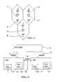
- FIG. 1shows a schematic diagram of a cellular radio network system in which embodiments of the invention can be implemented
- FIG. 2shows the hierarchy of various elements of the network of FIG. 1 ;
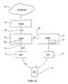
- FIG. 3shows two possible interfaces between network nodes
- FIG. 4is a flow chart for operation in accordance with one embodiment.
- FIG. 1in which three cells 1 , 2 , 3 of a cellular telecommunications network are shown.
- Each cell 1 , 2 , 3is served by a respective base transceiver station (BTS) 4 ′, 4 , 5 .
- Each base transceiver station (BTS)is arranged to transmit signals to and receive signals from the mobile stations (MS) 6 located in the cell associated with the given base transceiver station.
- MSmobile stations
- each mobile station 6is able to transmit signals to and receive signals from the respective base transceiver station 4 ′, 4 , 5 , and also able to move from the coverage area of one cell to the coverage area of another cell, e.g. from cell 2 to cell 3 .
- UMTSUniversal Mobile Telecommunications System
- CDMAcode division multiple access
- TDMAtime division multiple access
- FDMAfrequency division multiple access
- FIG. 2shows the hierarchy of a cellular communication system.
- the mobile station 6is in wireless communication with one of the base stations.
- a first base station 4is connected to a first network controller, which in FIG. 2 is a serving radio network controller SRNC 10 .
- SRNC 10serving radio network controller
- more than one base stationis usually connected to each controller 10 although only one is shown for clarity.
- more than one controlleris also provided in a network.
- the SRNC 10is connected to other elements of the network 12 via a suitable linking or gateway apparatus, such as a serving GPRS (General Packet radio Service) Support Node (SGSN) 14 .
- GPRSGeneral Packet radio Service
- SGSNServing GPRS
- the SRNC 10is arranged to control the base station, either directly or through an intermediate node (not shown).
- the controller 10passes on data to be transmitted to the mobile station by the base station.
- the controller 10will also receive from the base station data which the base station has received from the mobile station.
- the interfacemay comprise channels in both uplink and downlink directions.
- the datamay be sent between the mobile station and the controller in any suitable format.
- the messages sent from the mobile stationsmay include information identifying the mobile station (for instance, MS ID and/or IMSI (Mobile Station Identity and/or International Mobile Subscriber Identity, respectively)).
- the cellular telecommunications system of FIG. 2includes another controller RNC 11 controlling the base station 5 of cell 3 of FIG. 2 . It is, again, noted that the second controller may also control more than one base station. The second controller may also sometimes be referred to as a drift controller (DRNC).
- DRNCdrift controller
- the SNRC 10 and DRNC 11may communicate with each other over an open Iur interface 18 established between them.
- FIG. 2illustrates one possible relocation situation wherein the mobile station MS 6 or similar user equipment communicates firstly via the BTS 4 over a radio interface designated by a solid line and then switches to communicate via a new BTS 5 , as designated by the dashed radio interface.
- the change from one base station to anothermay occur after the mobile station 6 has moved into the service or illumination area of the second base station 5 .
- network optimizationload balancing, hardware congestion, connection quality improvement, fault in the system or base station and so on.
- At least some of the functionalities of the network elementshave to be relocated for the connection. For example, when a SRNC functionality is to be located from a first RNC to a second RNC some protocol termination points of an ongoing connection (such as RRC, RCL and/or MAC protocols) need to be changed from the first RNC to the second RNC.
- some protocol termination points of an ongoing connectionsuch as RRC, RCL and/or MAC protocols
- the protocol termination pointis illustrated to comprise a radio resource control (RRC) protocol.
- RRCradio resource control
- MACmedium access control
- RLCradio link control
- PDCPpacket data convergence protocol
- the SRNC 10 and DRNC 11each are provided with a Radio Resource Controller functionality RRC 24 and 26 , respectively.
- RRCRadio Resource Controller
- the MS 6is in communication with the controller 10
- the RRC protocolhas its other termination point correspondingly at the controller 10 , while the other termination point is at the mobile station.
- the termination point of the RRC protocolshould also be changed correspondingly.
- the new controller 11should be provided with a similar termination point functionality using similar parameters as the previous controller had.
- FIG. 3shows further an Iur interface 18 between the DRNC 10 and the SRNC 11 .
- a RNSAPRadio Network Subsystem Application Part
- a RANAPRadio Access Network Application Part; in the control plane
- L3Layer 3
- the core network element 14can be e.g. a mobile switching center or a serving GPRS support node.
- the protocol termination pointis to be moved between the termination points during an active state of the protocol between the servicing network controller and the mobile station.
- the “old” protocol termination point in the source network elementproduces at step 34 a special protocol data unit (PDU) containing predefined necessary protocol parameters for initialization of the second termination point before relocation of the connection.
- PDUis passed at step 36 to the new termination point with help of a second protocol.
- the second protocolis used for signaling between the different network elements or nodes.
- the passed informationcan be transparent to the second protocol used for the transmission of the PDU. Examples of the protocols which may be used for the transmission of the PDU will be discussed in more detail later in this specification.
- the new termination pointreceives the PDU and it is initialized at step 38 based on the information received from the old termination point. After the initialization procedure the termination point will be relocated at step 40 to the new network element and the operation of the system continues as before except that the protocol termination point of the active protocol is now situated in the new network element.
- an explicit protocol messagewill be passed between the old termination point and the new termination point of a protocol in case of relocation of the protocol termination point.
- the specified PDU(or message) is used within a protocol peer between the old and the new termination point of the protocol.
- a single protocoldefines the information to be transferred between the protocol peers and the information to be transmitted within one peer. By means of this it is possible to avoid a need for defining a great number of parameters of one protocol in another protocol. For example, by the embodiment described in the following about 100 RRC parameters in the RANAP protocol are avoided.
- a radio interface L3 protocoli.e. a radio resource control; RRC
- RRCradio resource control
- the exemplifying RRC protocolis known, and is not described in more detail. It is sufficient to note that the RRC provides common controlling and signaling over the air interface between the serving RNC and the mobile station and that the RRC can be shared with circuit switched traffic and packet switched traffic.
- the control unit 20 of the first (source) RNC 10produces the special protocol initialization unit which in this instance will be referred to as a RRC PDU.
- the RRC PDUcontains all such predefined RRC parameters that have to be known by the new termination point in order to receive and continue the connection. These parameters may include information concerning e.g. one or several of the following: radio bearer(s), transport channel(s), radio link(s) and their physical channels, capability information as well as user equipment capabilities and measurements being reported by the user equipment and so on.
- the RRC PDUcontains all such RRC parameters that are required by the termination point at the target RNC to start the RRC protocol in a relatively similar state and conditions that existed in the old termination point.
- the generated RRC PDUcan be transferred from the first RNC to the second RNC by means of a RNSAP (Radio Network Subsystem Application Part) over an open interface Iur 18 provided between the first controller 10 and the second controller 11 .
- the termination point at the second RNCreceives the RRC PDU and subsequently decodes the received RRC PDU.
- the termination point 26is initialized based on the received and decoded information. The initialization procedure can be controlled by the control unit 21 .
- the PDUis firstly moved from the source RNC 10 to the core network (CN) 14 over an Iu interface 19 by a RANAP (Radio Access Network Application Part) message ‘RELOCATION REQUIRED’ and subsequently from the core network to the target RNC 11 by an Iu RANAP message ‘RELOCATION REQUEST’.
- RANAPRadio Access Network Application Part
- the RRC PDUcan be encapsulated within a message in the second protocol as there is no need for the contents of the RRC PDU to be visible for the functionality of the second protocol, such as to the RANAP or the RNSAP.
- the encapsulation of protocol messages transparently to a message of another protocolis a known technique and will thus not be discussed in more detail herein
- a protocolmay “collect” required information for several protocols and generate a PDU containing required information for all or at least more than one of the protocols to be relocated.
- a separate or further protocol initialization unit PDUis used for each of the protocols to be relocated or at least some of the protocols to be relocated.
- the different protocol initialization unitscan be transferred between the termination point by protocols that are different to each other.
- protocol initialization unitis such that that the functionalities of the communication system may continue without disconnecting the user equipment from the communication system.
- the termination pointis not relocated from a network element or node to another node but within the node.
- the relocation of some or all functionalitiesmay also be triggered even in such conditions where the communication could continue without any relocation proceedings, e.g. in order to optimize the operation of the system or balance the load distribution in the system.
- the mobile station 6 of FIG. 2may be in communication with both controllers 10 and 11 .
- a user plane communicationmay be enabled via the Iur interface 18 of FIG. 2 , whereby the mobile station 6 within the service area of the controller 11 could still be controlled by the old servicing controller 10 via the controller 11 .
- the initializationis a bi-directional process.
- the new network elementmay send a response to the first element or accomplish a transmission to a further network element.
- the responsemay include a message such as “unable to initialize”, “overload”, “all parameters not received” and so on.
- the first network elementmay modify its state and/or take some other actions towards the new termination point. For example, transmit modified parameter or parameters, or use a different transmission route, or try to relocate the connection to another network element.
- the network element in questionmay become overloaded or a failure in the system of the network element itself may force the system to relocate at least a part of the functionalities; for purposes of network optimization; for purposes of load balancing, and so on.
Landscapes
- Engineering & Computer Science (AREA)
- Computer Networks & Wireless Communication (AREA)
- Signal Processing (AREA)
- Mobile Radio Communication Systems (AREA)
- Communication Control (AREA)
- Input Circuits Of Receivers And Coupling Of Receivers And Audio Equipment (AREA)
- Burglar Alarm Systems (AREA)
- Radio Relay Systems (AREA)
- Stored Programmes (AREA)
- Small-Scale Networks (AREA)
- Data Exchanges In Wide-Area Networks (AREA)
Abstract
Description
Claims (34)
Applications Claiming Priority (2)
| Application Number | Priority Date | Filing Date | Title |
|---|---|---|---|
| GBGB9921706.9AGB9921706D0 (en) | 1999-09-14 | 1999-09-14 | Relocation in a communication system |
| PCT/EP2000/009100WO2001020938A1 (en) | 1999-09-14 | 2000-09-13 | Relocation in a communication system |
Publications (1)
| Publication Number | Publication Date |
|---|---|
| US7242933B1true US7242933B1 (en) | 2007-07-10 |
Family
ID=10860889
Family Applications (1)
| Application Number | Title | Priority Date | Filing Date |
|---|---|---|---|
| US10/088,452Expired - LifetimeUS7242933B1 (en) | 1999-09-14 | 2000-09-13 | Relocation in a communication system |
Country Status (13)
| Country | Link |
|---|---|
| US (1) | US7242933B1 (en) |
| EP (2) | EP1212919B1 (en) |
| JP (1) | JP3602501B2 (en) |
| KR (1) | KR100531144B1 (en) |
| CN (1) | CN1178547C (en) |
| AT (1) | ATE480970T1 (en) |
| AU (1) | AU7657700A (en) |
| BR (1) | BR0013975B1 (en) |
| CA (1) | CA2384290C (en) |
| DE (1) | DE60044939D1 (en) |
| ES (1) | ES2348709T3 (en) |
| GB (1) | GB9921706D0 (en) |
| WO (1) | WO2001020938A1 (en) |
Cited By (9)
| Publication number | Priority date | Publication date | Assignee | Title |
|---|---|---|---|---|
| US20040146033A1 (en)* | 2001-02-09 | 2004-07-29 | Raul Soderstrom | Method, system and equipment for retransmission in communications systems |
| US20050148357A1 (en)* | 2004-01-05 | 2005-07-07 | Nokia Corporation | Radio network relocation |
| US20050193309A1 (en)* | 2003-08-21 | 2005-09-01 | Francesco Grilli | Methods for forward error correction coding above a radio link control layer and related apparatus |
| US20060223532A1 (en)* | 2003-04-03 | 2006-10-05 | Sheng Liu | Method for user equipment mobility management and communication system |
| US20070298800A1 (en)* | 2004-05-17 | 2007-12-27 | Ipwireless, Inc. | Arrangement And Method For Radio Network Relocation |
| US20080098283A1 (en)* | 2003-08-21 | 2008-04-24 | Qualcomm Incorporated | Outer coding methods for broadcast/multicast content and related apparatus |
| US20110182269A1 (en)* | 2008-06-23 | 2011-07-28 | Ntt Docomo, Inc. | Mobile communication method and mobile station |
| US8451770B2 (en) | 2002-05-06 | 2013-05-28 | Qualcomm Incorporated | Multi-media broadcast and multicast service (MBMS) in a wireless communication system |
| US8804761B2 (en)* | 2003-08-21 | 2014-08-12 | Qualcomm Incorporated | Methods for seamless delivery of broadcast and multicast content across cell borders and/or between different transmission schemes and related apparatus |
Families Citing this family (19)
| Publication number | Priority date | Publication date | Assignee | Title |
|---|---|---|---|---|
| JP3419386B2 (en) | 1999-09-08 | 2003-06-23 | 日本電気株式会社 | Paging system and paging method |
| DE10017062B4 (en) | 1999-11-22 | 2015-03-05 | Ipcom Gmbh & Co. Kg | Method for operating a mobile radio network |
| ATE440469T1 (en)* | 1999-11-29 | 2009-09-15 | Nokia Corp | TRANSMISSION OF ALGORITHM PARAMETERS WHEN PASSING A MOBILE STATION BETWEEN RADIO NETWORK SUBSYSTEMS |
| US6968190B1 (en) | 1999-11-29 | 2005-11-22 | Nokia Mobile Phones, Ltd. | Transfer of optimization algorithm parameters during handover of a mobile station between radio network subsystems |
| FR2818864B1 (en)* | 2000-12-21 | 2003-04-04 | Cit Alcatel | METHOD FOR REPORTING RADIO ACCESS CAPACITY INFORMATION FROM A MOBILE STATION TO A MOBILE RADIO COMMUNICATION NETWORK IN PACKET MODE |
| US20040100913A1 (en)* | 2001-03-28 | 2004-05-27 | Juha Kalliokulju | Method for providing parameters during a change of access, cellular communications system, user equipment and network element |
| GB2380104B (en) | 2001-07-06 | 2003-09-10 | Samsung Electronics Co Ltd | Method for resetting MAC layer entity in a communication system |
| US9635540B2 (en) | 2002-03-25 | 2017-04-25 | Jeffrey D. Mullen | Systems and methods for locating cellular phones and security measures for the same |
| US7133385B2 (en)* | 2002-03-29 | 2006-11-07 | Nortel Networks Limited | Network directed intersystem handoff for 1xEVD0 |
| US6990342B2 (en) | 2002-08-29 | 2006-01-24 | Motorola, Inx. | Method and apparatus for cell reselection within a communications system |
| DE602004009596T2 (en) | 2003-09-12 | 2008-07-24 | Ntt Docomo Inc. | SAFE HANDOVER WITHIN A TERRITORY AND TERRITORY |
| WO2005027558A1 (en)* | 2003-09-12 | 2005-03-24 | Ntt Docomo, Inc. | Context transfer for seamless handover |
| EP1519519B1 (en)* | 2003-09-23 | 2011-04-20 | Panasonic Corporation | Protocol context transfer in a mobile communication system |
| US20060099950A1 (en)* | 2004-11-08 | 2006-05-11 | Klein Thierry E | Method and apparatus for activating an inactive mobile unit in a distributed network |
| US7848749B2 (en)* | 2004-11-08 | 2010-12-07 | Alcatel-Lucent Usa Inc. | Method and apparatus for activating a dormant mobile unit in a distributed network |
| KR100670876B1 (en)* | 2005-05-09 | 2007-01-19 | 엘지노텔 주식회사 | How to relocate / handle RNS in WPC system |
| US7317707B2 (en) | 2005-06-02 | 2008-01-08 | Lucent Technologies Inc. | Method for seamless session transfer of a mobile station |
| US7920866B2 (en)* | 2005-07-07 | 2011-04-05 | Alcatel-Lucent Usa Inc. | Method of hard handover in a wireless communication system |
| CN101352093A (en) | 2007-01-08 | 2009-01-21 | 华为技术有限公司 | Forward the learned state information to the moving target node |
Citations (21)
| Publication number | Priority date | Publication date | Assignee | Title |
|---|---|---|---|---|
| US5189734A (en)* | 1988-11-16 | 1993-02-23 | U.S. Philips Corporation | Cellular radio system |
| CH682687A5 (en) | 1988-07-29 | 1993-10-29 | Gen Electric | Means for lubricating thrust bearings of a machine. |
| US5557745A (en)* | 1990-09-04 | 1996-09-17 | Digital Equipment Corporation | Method for supporting foreign protocols across backbone network by combining and transmitting list of destinations that support second protocol in first and second areas to the third area |
| EP0898438A2 (en) | 1997-08-20 | 1999-02-24 | Nokia Mobile Phones Ltd. | Method and system for controlling radio communications network and radio network controller |
| US5917811A (en)* | 1996-05-22 | 1999-06-29 | Qualcomm Incorporated | Method and apparatus for measurement directed hard handoff in a CDMA system |
| JPH11205842A (en) | 1998-01-12 | 1999-07-30 | Hitachi Ltd | Handover method between different mobile communication carrier networks, and gateway exchange |
| WO1999051051A2 (en) | 1998-03-31 | 1999-10-07 | Nokia Netwoks Oy | A method for controlling connections to a mobile station |
| US6201969B1 (en)* | 1998-06-02 | 2001-03-13 | Lucent Technologies Inc. | Control of handoff in CDMA cellular systems |
| US6301479B1 (en)* | 1999-07-08 | 2001-10-09 | Telefonaktiebolaget Lm Ericsson | Technique for providing a secure link in a mobile communication system |
| US6304556B1 (en)* | 1998-08-24 | 2001-10-16 | Cornell Research Foundation, Inc. | Routing and mobility management protocols for ad-hoc networks |
| US6374112B1 (en)* | 1998-04-03 | 2002-04-16 | Telefonaktiebolaget Lm Ericsson (Publ) | Flexible radio access and resource allocation in a universal mobile telephone system |
| US6473411B1 (en)* | 1997-05-12 | 2002-10-29 | Kabushiki Kaisha Toshiba | Router device, datagram transfer method and communication system realizing handoff control for mobile terminals |
| US6542743B1 (en)* | 1999-08-31 | 2003-04-01 | Qualcomm, Incorporated | Method and apparatus for reducing pilot search times utilizing mobile station location information |
| US6542516B1 (en)* | 1998-04-15 | 2003-04-01 | Nokia Mobile Phones Limited | Adaptation layer for realizing protocol adaptations in a digital wireless data transmission system |
| US6587680B1 (en)* | 1999-11-23 | 2003-07-01 | Nokia Corporation | Transfer of security association during a mobile terminal handover |
| US6628632B1 (en)* | 1999-07-19 | 2003-09-30 | Lucent Technologies Inc. | Method and apparatus for permitting direct handoff between base stations in a wireless network |
| US6658011B1 (en)* | 1999-04-19 | 2003-12-02 | Nokia Mobile Phones Ltd. | Use of wireless application protocol in a packet-switched radio telecommunication system |
| US6674765B1 (en)* | 1998-05-22 | 2004-01-06 | Lucent Technologies Inc. | Methods and apparatus for random chip delay access priority in a communications system |
| US6687249B1 (en)* | 1998-08-25 | 2004-02-03 | Telefonaktiebolaget Lm Ericsson | Reconfiguring diversity legs during CN-RNC interface streamlining |
| US6725038B1 (en)* | 1999-01-26 | 2004-04-20 | Nokia Corporation | Method and apparatus for speeding up AAL2 connection setup during handover in advanced cellular networks |
| US6912230B1 (en)* | 1999-02-05 | 2005-06-28 | Tecore | Multi-protocol wireless communication apparatus and method |
Family Cites Families (1)
| Publication number | Priority date | Publication date | Assignee | Title |
|---|---|---|---|---|
| CH682867A5 (en)* | 1991-09-24 | 1993-11-30 | Ascom Tech Ag | DECT radio hand-over for cellular mobile network - reserving free second protocol control unit and data interface, simultaneously transmitting data over the paths and breaking first path protocol |
- 1999
- 1999-09-14GBGBGB9921706.9Apatent/GB9921706D0/ennot_activeCeased
- 2000
- 2000-09-13CNCNB008128766Apatent/CN1178547C/ennot_activeCeased
- 2000-09-13KRKR10-2002-7003438Apatent/KR100531144B1/ennot_activeExpired - Lifetime
- 2000-09-13CACA002384290Apatent/CA2384290C/ennot_activeExpired - Lifetime
- 2000-09-13EPEP00966045Apatent/EP1212919B1/ennot_activeExpired - Lifetime
- 2000-09-13AUAU76577/00Apatent/AU7657700A/ennot_activeAbandoned
- 2000-09-13BRBRPI0013975-0B1Apatent/BR0013975B1/enactiveIP Right Grant
- 2000-09-13JPJP2001524385Apatent/JP3602501B2/ennot_activeExpired - Lifetime
- 2000-09-13ESES00966045Tpatent/ES2348709T3/ennot_activeExpired - Lifetime
- 2000-09-13ATAT00966045Tpatent/ATE480970T1/ennot_activeIP Right Cessation
- 2000-09-13WOPCT/EP2000/009100patent/WO2001020938A1/enactiveIP Right Grant
- 2000-09-13DEDE60044939Tpatent/DE60044939D1/ennot_activeExpired - Lifetime
- 2000-09-13USUS10/088,452patent/US7242933B1/ennot_activeExpired - Lifetime
- 2000-09-13EPEP10170344Apatent/EP2237609A3/ennot_activeWithdrawn
Patent Citations (22)
| Publication number | Priority date | Publication date | Assignee | Title |
|---|---|---|---|---|
| CH682687A5 (en) | 1988-07-29 | 1993-10-29 | Gen Electric | Means for lubricating thrust bearings of a machine. |
| US5189734A (en)* | 1988-11-16 | 1993-02-23 | U.S. Philips Corporation | Cellular radio system |
| US5557745A (en)* | 1990-09-04 | 1996-09-17 | Digital Equipment Corporation | Method for supporting foreign protocols across backbone network by combining and transmitting list of destinations that support second protocol in first and second areas to the third area |
| US5917811A (en)* | 1996-05-22 | 1999-06-29 | Qualcomm Incorporated | Method and apparatus for measurement directed hard handoff in a CDMA system |
| US6473411B1 (en)* | 1997-05-12 | 2002-10-29 | Kabushiki Kaisha Toshiba | Router device, datagram transfer method and communication system realizing handoff control for mobile terminals |
| EP0898438A2 (en) | 1997-08-20 | 1999-02-24 | Nokia Mobile Phones Ltd. | Method and system for controlling radio communications network and radio network controller |
| US6574473B2 (en)* | 1997-08-20 | 2003-06-03 | Nokia Mobile Phones, Ltd. | Method and system for controlling radio communications network and radio network controller |
| JPH11205842A (en) | 1998-01-12 | 1999-07-30 | Hitachi Ltd | Handover method between different mobile communication carrier networks, and gateway exchange |
| WO1999051051A2 (en) | 1998-03-31 | 1999-10-07 | Nokia Netwoks Oy | A method for controlling connections to a mobile station |
| US6374112B1 (en)* | 1998-04-03 | 2002-04-16 | Telefonaktiebolaget Lm Ericsson (Publ) | Flexible radio access and resource allocation in a universal mobile telephone system |
| US6542516B1 (en)* | 1998-04-15 | 2003-04-01 | Nokia Mobile Phones Limited | Adaptation layer for realizing protocol adaptations in a digital wireless data transmission system |
| US6674765B1 (en)* | 1998-05-22 | 2004-01-06 | Lucent Technologies Inc. | Methods and apparatus for random chip delay access priority in a communications system |
| US6201969B1 (en)* | 1998-06-02 | 2001-03-13 | Lucent Technologies Inc. | Control of handoff in CDMA cellular systems |
| US6304556B1 (en)* | 1998-08-24 | 2001-10-16 | Cornell Research Foundation, Inc. | Routing and mobility management protocols for ad-hoc networks |
| US6687249B1 (en)* | 1998-08-25 | 2004-02-03 | Telefonaktiebolaget Lm Ericsson | Reconfiguring diversity legs during CN-RNC interface streamlining |
| US6725038B1 (en)* | 1999-01-26 | 2004-04-20 | Nokia Corporation | Method and apparatus for speeding up AAL2 connection setup during handover in advanced cellular networks |
| US6912230B1 (en)* | 1999-02-05 | 2005-06-28 | Tecore | Multi-protocol wireless communication apparatus and method |
| US6658011B1 (en)* | 1999-04-19 | 2003-12-02 | Nokia Mobile Phones Ltd. | Use of wireless application protocol in a packet-switched radio telecommunication system |
| US6301479B1 (en)* | 1999-07-08 | 2001-10-09 | Telefonaktiebolaget Lm Ericsson | Technique for providing a secure link in a mobile communication system |
| US6628632B1 (en)* | 1999-07-19 | 2003-09-30 | Lucent Technologies Inc. | Method and apparatus for permitting direct handoff between base stations in a wireless network |
| US6542743B1 (en)* | 1999-08-31 | 2003-04-01 | Qualcomm, Incorporated | Method and apparatus for reducing pilot search times utilizing mobile station location information |
| US6587680B1 (en)* | 1999-11-23 | 2003-07-01 | Nokia Corporation | Transfer of security association during a mobile terminal handover |
Cited By (22)
| Publication number | Priority date | Publication date | Assignee | Title |
|---|---|---|---|---|
| US7522560B2 (en)* | 2001-02-09 | 2009-04-21 | Telefonaktiebolaget Lm Ericsson (Publ) | Method, system and equipment for retransmission in communications systems |
| US20040146033A1 (en)* | 2001-02-09 | 2004-07-29 | Raul Soderstrom | Method, system and equipment for retransmission in communications systems |
| US8451770B2 (en) | 2002-05-06 | 2013-05-28 | Qualcomm Incorporated | Multi-media broadcast and multicast service (MBMS) in a wireless communication system |
| US20060223532A1 (en)* | 2003-04-03 | 2006-10-05 | Sheng Liu | Method for user equipment mobility management and communication system |
| US8175090B2 (en) | 2003-08-21 | 2012-05-08 | Qualcomm Incorporated | Outer coding methods for broadcast/multicast content and related apparatus |
| US8171381B2 (en) | 2003-08-21 | 2012-05-01 | Qualcomm Incorporated | Outer coding methods for broadcast/multicast content and related apparatus |
| US20080141094A1 (en)* | 2003-08-21 | 2008-06-12 | Qualcomm Incorporated | Outer coding methods for broadcast/multicast content and related apparatus |
| US20080141097A1 (en)* | 2003-08-21 | 2008-06-12 | Qualcomm Incorporated | Outer coding methods for broadcast/multicast content and related apparatus |
| US8804761B2 (en)* | 2003-08-21 | 2014-08-12 | Qualcomm Incorporated | Methods for seamless delivery of broadcast and multicast content across cell borders and/or between different transmission schemes and related apparatus |
| US20080151805A1 (en)* | 2003-08-21 | 2008-06-26 | Qualcomm Incorporated | Outer coding methods for broadcast/multicast content and related apparatus |
| US8694869B2 (en) | 2003-08-21 | 2014-04-08 | QUALCIMM Incorporated | Methods for forward error correction coding above a radio link control layer and related apparatus |
| US8291300B2 (en) | 2003-08-21 | 2012-10-16 | Qualcomm Incorporated | Outer coding methods for broadcast/multicast content and related apparatus |
| US20050193309A1 (en)* | 2003-08-21 | 2005-09-01 | Francesco Grilli | Methods for forward error correction coding above a radio link control layer and related apparatus |
| US20080098283A1 (en)* | 2003-08-21 | 2008-04-24 | Qualcomm Incorporated | Outer coding methods for broadcast/multicast content and related apparatus |
| US8019374B2 (en) | 2004-01-05 | 2011-09-13 | Nokia Corporation | Radio network relocation |
| US20050148357A1 (en)* | 2004-01-05 | 2005-07-07 | Nokia Corporation | Radio network relocation |
| US20080214195A1 (en)* | 2004-01-05 | 2008-09-04 | Nokia Corporation | Radio network relocation |
| US7389121B2 (en)* | 2004-01-05 | 2008-06-17 | Nokia Corporation | Radio network relocation |
| US20070298800A1 (en)* | 2004-05-17 | 2007-12-27 | Ipwireless, Inc. | Arrangement And Method For Radio Network Relocation |
| US8483687B2 (en)* | 2004-05-17 | 2013-07-09 | Nvidia Corporation | Arrangement and method for radio network relocation |
| US20110182269A1 (en)* | 2008-06-23 | 2011-07-28 | Ntt Docomo, Inc. | Mobile communication method and mobile station |
| US8576799B2 (en)* | 2008-06-23 | 2013-11-05 | Ntt Docomo, Inc. | Mobile communication method and mobile station |
Also Published As
| Publication number | Publication date |
|---|---|
| EP2237609A2 (en) | 2010-10-06 |
| ES2348709T3 (en) | 2010-12-13 |
| CN1373979A (en) | 2002-10-09 |
| DE60044939D1 (en) | 2010-10-21 |
| EP1212919A1 (en) | 2002-06-12 |
| CA2384290A1 (en) | 2001-03-22 |
| JP3602501B2 (en) | 2004-12-15 |
| AU7657700A (en) | 2001-04-17 |
| CA2384290C (en) | 2005-11-15 |
| EP1212919B1 (en) | 2010-09-08 |
| CN1178547C (en) | 2004-12-01 |
| EP2237609A3 (en) | 2010-10-27 |
| KR20020040803A (en) | 2002-05-30 |
| ATE480970T1 (en) | 2010-09-15 |
| BR0013975B1 (en) | 2013-08-27 |
| BR0013975A (en) | 2002-07-02 |
| KR100531144B1 (en) | 2005-11-28 |
| JP2003509981A (en) | 2003-03-11 |
| GB9921706D0 (en) | 1999-11-17 |
| WO2001020938A1 (en) | 2001-03-22 |
Similar Documents
| Publication | Publication Date | Title |
|---|---|---|
| US7242933B1 (en) | Relocation in a communication system | |
| EP1360864B1 (en) | Paging method and system for a radio access network | |
| US7693524B2 (en) | Radio access network apparatus and mobile communication system using the same | |
| JP3917427B2 (en) | Connections in communication systems | |
| EP1657862B1 (en) | Centralized dynamical resource reservation method based on the exchange of service specific capacity settings in a multi-RAT network | |
| US6721566B2 (en) | Cell update in a cellular communications system | |
| US7664265B2 (en) | Controlling communications between stations | |
| KR100378895B1 (en) | RAU optimisation in standby state | |
| US7792078B2 (en) | Forwarding a terminal identity between core network nodes | |
| JP4885375B2 (en) | Method for providing multipoint connectivity to a subscriber of a wireless communication system | |
| EP1410664A1 (en) | Ip-based gsm and umts system | |
| EP1429567B1 (en) | Improved OpenRAN architecture for Radio Network Controller, Mobile Communication System and method of controlling Radio Base Station device | |
| GB2371179A (en) | Cell updates in a UMTS terrestrial radio access network | |
| US20060080387A1 (en) | Communications network |
Legal Events
| Date | Code | Title | Description |
|---|---|---|---|
| AS | Assignment | Owner name:NOKIA CORPORATION, FINLAND Free format text:ASSIGNMENT OF ASSIGNORS INTEREST;ASSIGNOR:AHMAVAARA, KALLE;REEL/FRAME:013092/0132 Effective date:20020522 | |
| STCF | Information on status: patent grant | Free format text:PATENTED CASE | |
| CC | Certificate of correction | ||
| CC | Certificate of correction | ||
| FPAY | Fee payment | Year of fee payment:4 | |
| AS | Assignment | Owner name:VRINGO INFRASTRUCTURE INC., NEW YORK Free format text:ASSIGNMENT OF ASSIGNORS INTEREST;ASSIGNOR:NOKIA CORPORATION;REEL/FRAME:029010/0345 Effective date:20120910 | |
| FPAY | Fee payment | Year of fee payment:8 | |
| AS | Assignment | Owner name:VRINGO, INC., NEW YORK Free format text:SECURITY INTEREST;ASSIGNOR:VRINGO INFRASTRUCTURE, INC.;REEL/FRAME:035585/0371 Effective date:20150504 | |
| AS | Assignment | Owner name:IROQUOIS MASTER FUND, L.P., NEW YORK Free format text:ASSIGNMENT OF SECURITY INTEREST;ASSIGNOR:VRINGO, INC.;REEL/FRAME:035624/0710 Effective date:20150404 | |
| AS | Assignment | Owner name:VRINGO, INC., NEW YORK Free format text:RELEASE BY SECURED PARTY;ASSIGNOR:SILICON VALLEY BANK;REEL/FRAME:038380/0956 Effective date:20160406 | |
| AS | Assignment | Owner name:NOKIA TECHNOLOGIES OY, FINLAND Free format text:ASSIGNMENT OF ASSIGNORS INTEREST;ASSIGNOR:FORM HOLDINGS CORP. (FORMERLY VRINGO INC.);REEL/FRAME:045921/0512 Effective date:20171220 | |
| MAFP | Maintenance fee payment | Free format text:PAYMENT OF MAINTENANCE FEE, 12TH YEAR, LARGE ENTITY (ORIGINAL EVENT CODE: M1553); ENTITY STATUS OF PATENT OWNER: LARGE ENTITY Year of fee payment:12 |