US7242398B2 - Flexible display device - Google Patents
Flexible display deviceDownload PDFInfo
- Publication number
- US7242398B2 US7242398B2US10/468,321US46832104AUS7242398B2US 7242398 B2US7242398 B2US 7242398B2US 46832104 AUS46832104 AUS 46832104AUS 7242398 B2US7242398 B2US 7242398B2
- Authority
- US
- United States
- Prior art keywords
- substrate
- display device
- connection line
- row
- display
- Prior art date
- Legal status (The legal status is an assumption and is not a legal conclusion. Google has not performed a legal analysis and makes no representation as to the accuracy of the status listed.)
- Expired - Lifetime, expires
Links
- 239000000758substrateSubstances0.000claimsabstractdescription55
- 238000004519manufacturing processMethods0.000claimsabstractdescription11
- 238000000034methodMethods0.000claimsdescription35
- 239000002184metalSubstances0.000claimsdescription13
- 238000009413insulationMethods0.000claimsdescription7
- 238000001020plasma etchingMethods0.000claimsdescription7
- 238000005459micromachiningMethods0.000claimsdescription6
- 230000000873masking effectEffects0.000claimsdescription4
- 238000001465metallisationMethods0.000claimsdescription4
- 238000000059patterningMethods0.000claimsdescription4
- 230000002708enhancing effectEffects0.000claimsdescription2
- 239000010410layerSubstances0.000description19
- 229920003023plasticPolymers0.000description5
- 238000005452bendingMethods0.000description2
- 238000001459lithographyMethods0.000description2
- 239000012044organic layerSubstances0.000description2
- 239000004065semiconductorSubstances0.000description2
- 230000002411adverseEffects0.000description1
- 238000000151depositionMethods0.000description1
- 230000008021depositionEffects0.000description1
- 238000005137deposition processMethods0.000description1
- 238000005538encapsulationMethods0.000description1
- 238000005530etchingMethods0.000description1
- 229920002457flexible plasticPolymers0.000description1
- 238000002955isolationMethods0.000description1
- 239000000203mixtureSubstances0.000description1
- 238000012986modificationMethods0.000description1
- 230000004048modificationEffects0.000description1
- 229920000642polymerPolymers0.000description1
- 230000000644propagated effectEffects0.000description1
- 239000010409thin filmSubstances0.000description1
Images


Classifications
- H—ELECTRICITY
- H10—SEMICONDUCTOR DEVICES; ELECTRIC SOLID-STATE DEVICES NOT OTHERWISE PROVIDED FOR
- H10K—ORGANIC ELECTRIC SOLID-STATE DEVICES
- H10K59/00—Integrated devices, or assemblies of multiple devices, comprising at least one organic light-emitting element covered by group H10K50/00
- H10K59/10—OLED displays
- H10K59/12—Active-matrix OLED [AMOLED] displays
- H10K59/131—Interconnections, e.g. wiring lines or terminals
- H—ELECTRICITY
- H10—SEMICONDUCTOR DEVICES; ELECTRIC SOLID-STATE DEVICES NOT OTHERWISE PROVIDED FOR
- H10D—INORGANIC ELECTRIC SEMICONDUCTOR DEVICES
- H10D86/00—Integrated devices formed in or on insulating or conducting substrates, e.g. formed in silicon-on-insulator [SOI] substrates or on stainless steel or glass substrates
- H10D86/40—Integrated devices formed in or on insulating or conducting substrates, e.g. formed in silicon-on-insulator [SOI] substrates or on stainless steel or glass substrates characterised by multiple TFTs
- H10D86/451—Integrated devices formed in or on insulating or conducting substrates, e.g. formed in silicon-on-insulator [SOI] substrates or on stainless steel or glass substrates characterised by multiple TFTs characterised by the compositions or shapes of the interlayer dielectrics
- H—ELECTRICITY
- H10—SEMICONDUCTOR DEVICES; ELECTRIC SOLID-STATE DEVICES NOT OTHERWISE PROVIDED FOR
- H10K—ORGANIC ELECTRIC SOLID-STATE DEVICES
- H10K50/00—Organic light-emitting devices
- H10K50/80—Constructional details
- H—ELECTRICITY
- H10—SEMICONDUCTOR DEVICES; ELECTRIC SOLID-STATE DEVICES NOT OTHERWISE PROVIDED FOR
- H10K—ORGANIC ELECTRIC SOLID-STATE DEVICES
- H10K59/00—Integrated devices, or assemblies of multiple devices, comprising at least one organic light-emitting element covered by group H10K50/00
- H10K59/10—OLED displays
- H10K59/12—Active-matrix OLED [AMOLED] displays
- H—ELECTRICITY
- H10—SEMICONDUCTOR DEVICES; ELECTRIC SOLID-STATE DEVICES NOT OTHERWISE PROVIDED FOR
- H10K—ORGANIC ELECTRIC SOLID-STATE DEVICES
- H10K59/00—Integrated devices, or assemblies of multiple devices, comprising at least one organic light-emitting element covered by group H10K50/00
- H10K59/80—Constructional details
- H—ELECTRICITY
- H10—SEMICONDUCTOR DEVICES; ELECTRIC SOLID-STATE DEVICES NOT OTHERWISE PROVIDED FOR
- H10K—ORGANIC ELECTRIC SOLID-STATE DEVICES
- H10K77/00—Constructional details of devices covered by this subclass and not covered by groups H10K10/80, H10K30/80, H10K50/80 or H10K59/80
- H10K77/10—Substrates, e.g. flexible substrates
- H10K77/111—Flexible substrates
- H—ELECTRICITY
- H10—SEMICONDUCTOR DEVICES; ELECTRIC SOLID-STATE DEVICES NOT OTHERWISE PROVIDED FOR
- H10K—ORGANIC ELECTRIC SOLID-STATE DEVICES
- H10K2102/00—Constructional details relating to the organic devices covered by this subclass
- H10K2102/301—Details of OLEDs
- H10K2102/311—Flexible OLED
- Y—GENERAL TAGGING OF NEW TECHNOLOGICAL DEVELOPMENTS; GENERAL TAGGING OF CROSS-SECTIONAL TECHNOLOGIES SPANNING OVER SEVERAL SECTIONS OF THE IPC; TECHNICAL SUBJECTS COVERED BY FORMER USPC CROSS-REFERENCE ART COLLECTIONS [XRACs] AND DIGESTS
- Y02—TECHNOLOGIES OR APPLICATIONS FOR MITIGATION OR ADAPTATION AGAINST CLIMATE CHANGE
- Y02E—REDUCTION OF GREENHOUSE GAS [GHG] EMISSIONS, RELATED TO ENERGY GENERATION, TRANSMISSION OR DISTRIBUTION
- Y02E10/00—Energy generation through renewable energy sources
- Y02E10/50—Photovoltaic [PV] energy
- Y02E10/549—Organic PV cells
Definitions
- the present inventionrelates generally to a display device. More particularly, the invention relates to a flexible display device, which can be rolled up in a preferential direction. The invention also relates to a method of manufacturing such flexible display devices.
- a display panel deviceconsists of a substrate layer, a number of display pixels disposed on the surface of the substrate, and pixel switching circuitry.
- the display pixelsare arranged in a form of plural rows and columns.
- a flexible display devicecomprises (a) a flexible substrate; (b) a plurality of display pixels arranged in a form of rows and columns on the surface of the substrate; (c) a plurality of first grooves in the surface of the substrate, the first groove being formed in between adjacent two rows or columns of the display pixels, thereby providing flexibility to the display device and, at the same time, minimizing the propagation of mechanical stress caused when the display device is bent or rolled; and (d) a plurality of connection lines for electrically interconnecting the plurality of display pixels.
- the display devicecan further include a plurality of second grooves, each of which is formed in between adjacent two columns or rows of the display pixels thereby enhancing the flexibility of the display device, the first and second grooves being substantially perpendicular to each other.
- a flexible display devicecomprising (a) a flexible substrate having a first and second surfaces; (b) a plurality of display pixels arranged in a form of rows and columns on the first surface of the substrate; (c) a plurality of first parallel grooves in the first surface of the substrate, the first groove being formed in between adjacent two rows or columns of the display pixels, thereby providing flexibility to the display device and, at the same time, minimizing the propagation of mechanical stress caused when the display device is bent or rolled; and (d) a plurality of connection lines for electrically interconnecting the plurality of display pixels.
- connection linescomprise: (a) a plurality of row connection lines provided on the second surface of the substrate, each row connection line corresponding to each respective row of display pixels; (b) a plurality of column connection lines provided on the second surface of the substrate, each column connection line corresponding to each respective column of display pixels; and (c) a plurality of vertical connection lines each connecting each display pixel on the first surface with a corresponding row or column connection line on the second surface, wherein an insulation layer is provided between the row and column connection lines.
- a method of manufacturing a flexible display devicecomprises the steps of: (a) providing a flexible substrate having a first and second surface; (b) forming a plurality of first parallel grooves in the first surface of the substrate, each adjacent two parallel grooves defining a pixel area therebetween; (c) providing a plurality of display pixels on the pixel area such that the display pixels are arranged in a pattern of rows and columns; and (d) providing a plurality of connection lines to electrically interconnect the display pixels.
- the methodcan further include a step of forming a plurality of second parallel grooves in the first surface of the substrate such that the second groove is substantially perpendicular to the first groove.
- the step of providing a plurality of connection linecomprises steps of: (a) providing a first connection line to connect the first surface with the second surface of the substrate; and (b) providing a second connection line on the second surface of the substrate such that the first connection line serves to electrically connect the display pixel on the first surface to the second connection line on the second surface.
- the step of providing a first connection linecomprises steps of: (a) forming a through-hole passing through the first and second surfaces of the substrate; and (b) carrying out metallization in the through-hole.
- FIG. 1illustrates a schematic sectional view of a flexible display device according to the first embodiment of the present invention
- FIG. 2shows the top view of the flexible display device of FIG. 1 ;
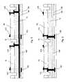
- FIG. 3is a schematic representation of a sectional view of a flexible display device according to the second embodiment of the present invention.
- FIG. 4depicts the top view of the flexible display device of FIG. 3 ;
- FIG. 5is a schematic cross-sectional view taken along the line A—A in FIG. 4 with the pixel electronics omitted;
- FIG. 6is a schematic cross-sectional view taken along the line B—B in FIG. 4 with the pixel electronic omitted;
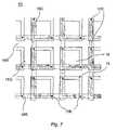
- FIG. 7illustrates a top plan view of a flexible display device according to the third embodiment of the invention.
- FIGS. 8 a to 8 jsequentially illustrate a manufacturing process of the flexible display device in accordance with the fourth embodiment of the invention.
- FIGS. 9 a to 9 rshow sequential steps of a manufacturing process of the flexible display device in accordance with the fifth embodiment of the invention.
- FIGS. 1 and 2there is schematically illustrated a flexible display device in accordance with the first embodiment of the present invention, which is generally denoted by a reference numeral 10 .
- FIG. 1is the cross-sectional view of the display device, and
- FIG. 2illustrates the top plan view thereof.
- the flexible display device 10comprises a flexible substrate 12 such as a plastic substrate, a plurality of display pixels 14 provided on the surface of the substrate 12 , a plurality of grooves 16 formed between the display pixels 14 , and a plurality of connection lines 18 for electrically interconnecting the display pixels 14 .
- the display pixels 14are arranged in a pattern of plural rows and columns as is shown in FIG. 2 .
- the groove 16can be formed in between any adjacent rows or columns of the display pixels, for example, in a regular pattern.
- the grooves 16are provided in between every adjacent two columns of display pixels and formed substantially parallel to the columns.
- connection lines 18include a plural of column connection lines 18 C and a plural of row connection lines 18 R, which serve to electronically interconnect the columns and rows of display pixels respectively, as is illustrated in FIGS. 2 .
- An insulation layer(not shown in FIGS. 1 and 2 ) is provided between the row and column connection lines 18 R and 18 C, which are substantially perpendicular to each other.
- the grooves 16define a pixel area 13 in-between where the display pixels 14 are placed. Accordingly, by virtue of the grooves 16 , the pixel area 13 is mechanically isolated, and the whole display device 10 is provided with a greater flexibility, especially to the extent that it can be rolled up or folded.
- the mechanical isolation of the pixel area 13serves to minimize the stress propagation from the substrate 12 to the pixel area 13 , i.e., the display pixels 14 when rolled or bent. That is, the minimal influence on display performance characteristics can be achieved. Therefore, the display device 10 of the invention can be stored in a compact rolled state, for example, in a cylindrical casing, and can be flattened out when in use. Furthermore, the flexible display device 10 can operate even when it remains bent or wrapped around a cylindrical surface.
- the display device 10is provided with a plural of columnar grooves 16 only, it can further include a plural of row grooves 16 R as illustrated in FIG. 7 .
- Each row groove 16 Ris provided in between each adjacent two rows of display pixels, thereby improving the flexibility of the display device.
- the column and row grooves 16 C, 16 Rare substantially perpendicular to each other.
- the grooves 16can take either a rectangular or rounded cross-section.
- Each display pixel 14includes an electro-luminescent display layer such as a polymer or organic emitting diode (OLED) and pixel electronics such as thin-film-transistor based switching circuitry.
- the pixel electronicscan be integrated in a stacked pixel configuration on the pixel area 13 .
- FIGS. 3 to 6schematically depict a flexible display device 10 in accordance with the second embodiment of the present invention.
- FIG. 3is the cross-sectional view of the display device, and
- FIG. 4illustrates the top plan view thereof.
- FIGS. 5 and 6are cross-sectional views taken along the lines A—A and B—B respectively in FIG. 4 .
- the flexible display device 10 of FIGS. 3 to 6comprises a flexible substrate 12 such as a plastic substrate, a plurality of display pixels 14 provided on the surface of the substrate 12 , a plurality of grooves 16 formed between the display pixels 14 , and a plurality of connection lines 17 and 18 for electrically interconnecting the display pixels 14 .
- the configuration of the elementsis essentially identical in both embodiments, except for that of the connection lines.
- connection line of this embodimentwill be described hereafter in greater detail.
- connection line for electrically interconnecting the display pixelscomprise a plural of row connection lines 18 R, a plural of column connection lines 18 C, and a plural of vertical connection lines 17 .
- the row and column connection lines 18 R and 18 Care provided on the opposite side to the surface of the substrate 12 where the display pixels 14 are disposed.
- An insulation layer 19 ais provided between the row and column connection lines 18 R, 18 C, as clearly illustrated in FIGS. 5 and 6 .
- the vertical connection line 17serves to connect each display pixel 14 , for example a pixel contact 15 (on which the display pixel is integrated) with each corresponding row or column connection lines. More specifically, the vertical connection line 17 includes a column vertical connection line 17 C and a row vertical connection line 17 R.
- each display pixel 14is provided with a row vertical connection line 17 R and a column vertical connection line 17 C, which electronically connect the display pixel 14 to a corresponding row and column connection lines 18 R, 18 C respectively, as clearly depicted in FIGS. 5 and 6 . Further detail of the connection lines 17 , 18 will be described hereinafter, in conjunction with manufacturing processes of the flexible display of the invention.
- FIG. 7there is schematically shown a top plan view of a flexible display device in accordance with the third embodiment of the invention.
- the display device of the inventioncan be further provided with a plurality of row grooves 16 R together with a plurality of column grooves 16 C, thereby improving the flexibility of the display device.
- each row grooveis formed in between each adjacent two rows of display pixels 14 .
- the methodin general, includes a step of forming a number of parallel grooves in the surface of a flexible substrate, such that a columnar pixel area is defined between each adjacent two grooves as illustrated in FIGS. 2 and 4 .
- the parallel groovescan consist of a plurality of parallel row grooves and a plurality of parallel column grooves. In this case, each adjacent two row grooves define an isolated pixel area in combination with each adjacent two column grooves, as shown in FIG. 7 .
- a number of display pixelsare provided on the pixel area defined between the grooves such that the display pixels are arranged in a form of parallel rows and columns, and the row and column of pixels are parallel with the row and column grooves respectively.
- the method of the inventionalso includes a step of forming a connection line to electronically interconnect the display pixels, depending on the design of the display device. Details of the above steps will be described hereinafter, in conjunction with FIGS. 8 a to 9 r.
- FIGS. 8 a to 8 jthere is sequentially and schematically illustrated a method of manufacturing a flexible display device in accordance with the fourth embodiment of the invention. The method will be explained in greater detail hereafter.
- FIGS. 8 a to 8 dshow, in sequence, a process of forming a plurality of grooves in the surface of a flexible substrate 12 .
- the grooves 16can be formed in the flexible plastic substrate 12 by using, for example, a metal (or other) masking technique and reactive ion etching (RIE) process in an atmosphere of CF 4 +O 2 mixture. That is, a thin-film metal 12 a is first deposited on the flexible substrate 12 and then patterned according to a desired outline and dimensions of the grooves as shown in FIG. 8 b .
- RIEreactive ion etching
- the metal-patterned substrateis transferred into a RIE chamber, where the area of the substrate surface which is free from the metal 12 a is etched and eventually results in the grooves 16 as depicted in FIG. 8 c .
- the metal mask 12 ais removed by using a wet etchant, or the like as shown in FIG. 8 d .
- the grooves in the plastic substratecan be formed by means of a laser micromachining process or a projection laser micromachining process, which are well-known in the art.
- the depth and width of the groovescan be controlled during the above processes such that the mechanical integrity of the substrate can be maintained while minimizing the influence on display performance characteristics.
- FIGS. 8 e to 8 jsequentially illustrate the step of providing a display pixel 14 and a connection line 18 between adjacent pixels.
- the display pixel 14associates various pixel electronics, including conducting layers, several dielectric layers 11 a , 11 c and 11 d , and can electrode 11 b , a source and drain metal 11 f , an OLED (Organic Light Emitting Diode) cathode 11 e , an organic layer 11 g , or the like.
- OLEDOrganic Light Emitting Diode
- FIGS. 8 e to 8 jsequentially illustrate the step of providing a display pixel 14 and a connection line 18 between adjacent pixels.
- the display pixel 14associates various pixel electronics, including conducting layers, several dielectric layers 11 a , 11 c and 11 d , and can electrode 11 b , a source and drain metal 11 f , an OLED (Organic Light Emitting Diode) cathode 11 e , an organic layer 11
- FIGS. 9 a to 9 rthere is sequentially and schematically illustrated a method of manufacturing a flexible display device in accordance with the fifth embodiment of the invention. The method will be explained in greater detail, referring to the flexible display device shown in FIGS. 3 to 6 .
- the step of forming a connection line between the display pixelsis different from that of the previous one.
- the step of forming the connection linesincludes steps of providing a first connection line perforating a flexible substrate, and providing a second connection line on the opposite side to the surface of the substrate where the display pixels are placed, such that the first connection line serves to electrically connects the display pixel on the surface to the second connection line.
- the first connection lineis denoted by reference numerals 17 C or 17 R, and the second connection line by 18 C or 18 R.
- the first connection lines 17 C, 17 Rcorrespond to the vertical connection lines 17 C, 17 R in FIGS. 3 to 6 .
- the step of providing a first connection linecomprises steps of forming a through-hole passing through the substrate, and carrying out metallization in the through-hole.
- FIGS. 9 a to 9 fshow the forming procedures of a first connection line 17 C or 17 R.
- the step of making a through-hole 11is similar to the groove forming process described above in conjunction with FIGS. 8 a to 8 d . That is, a metal masking and patterning process and a reactive ion etching (RIE) process, a laser micromachining process, or a projection laser micromachining process can be utilized, which are well-known processes in the art.
- RIEreactive ion etching
- a metal layer 12 bsuch as an Al layer is provided on the opposite side to the substrate surface where the metal masking 12 a is deposited. The metal layer 12 b is used for providing the second connection lines 18 C and 18 R in subsequent steps of the method.
- FIGS. 9 e and 9 fschematically illustrate the step of metallizing the through-holes 11 to forming the first connection lines 17 C and 17 R.
- Various conventional processescan be used for metallization of the through-holes 11 , including an electro- or electroless deposition process.
- FIGS. 9 g to 9 lthere is schematically depicted the step of providing the second connection lines 18 C and 18 R.
- a second connection line 18 Cis formed, which corresponds to the column connection line in FIGS. 4 to 6 .
- a first insulation layer 19 asuch as a dielectric layer is deposited over the second connection line 18 C.
- opening vias in the insulation layer 19 a , and deposition and patterning another metal layerare carried out to provide another second connection line 18 R, which corresponds to the row connection line in FIGS. 4 to 6 .
- another insulation layer 19 bsuch as a dielectric encapsulation layer is provided above the second connection line 18 R, as shown in FIG. 9 l.
- the grooves 16are formed by means of the same processes noted above, in conjunction with the previous embodiment of FIGS. 8 a to 8 j .
- the grooves 16define a pixel area 13 .
- FIGS. 9 n to 9 rschematically and sequentially illustrate the step of providing a display pixel 14 .
- the display pixel 14associates various pixel electronics, including conducting layers, several dielectric layers, a electrode, a source and drain metal, an OLED cathode, an organic layer, or the like.
- an OLED deviceis illustrated as a display pixel, various other types of pixel devices can be applied to the present invention.
- the above display pixel and related componentscan be formed by means of various conventional semiconductor processes such as lithography or the like.
Landscapes
- Engineering & Computer Science (AREA)
- Microelectronics & Electronic Packaging (AREA)
- Physics & Mathematics (AREA)
- Optics & Photonics (AREA)
- Devices For Indicating Variable Information By Combining Individual Elements (AREA)
- Electroluminescent Light Sources (AREA)
Abstract
Description
Claims (11)
Applications Claiming Priority (1)
| Application Number | Priority Date | Filing Date | Title |
|---|---|---|---|
| PCT/CA2002/000181WO2002067329A1 (en) | 2001-02-16 | 2002-02-18 | Flexible display device |
Publications (2)
| Publication Number | Publication Date |
|---|---|
| US20040124763A1 US20040124763A1 (en) | 2004-07-01 |
| US7242398B2true US7242398B2 (en) | 2007-07-10 |
Family
ID=32601843
Family Applications (1)
| Application Number | Title | Priority Date | Filing Date |
|---|---|---|---|
| US10/468,321Expired - LifetimeUS7242398B2 (en) | 2002-02-18 | 2002-02-18 | Flexible display device |
Country Status (1)
| Country | Link |
|---|---|
| US (1) | US7242398B2 (en) |
Cited By (29)
| Publication number | Priority date | Publication date | Assignee | Title |
|---|---|---|---|---|
| US20060204675A1 (en)* | 2005-03-08 | 2006-09-14 | Eastman Kodak Company | Display device with improved flexibility |
| WO2009055920A1 (en)* | 2007-10-29 | 2009-05-07 | Ignis Innovation Inc. | High aperture ratio pixel layout for display device |
| US20120258573A1 (en)* | 2008-12-15 | 2012-10-11 | Industrial Technology Research Institute | Fabrication method of substrate |
| US20140354558A1 (en)* | 2013-05-31 | 2014-12-04 | Samsung Display Co., Ltd. | Flexible touch screen panel and flexible display apparatus including the same |
| US20150146386A1 (en)* | 2013-11-28 | 2015-05-28 | Samsung Display Co., Ltd. | Flexible display device |
| US20150236045A1 (en)* | 2014-02-18 | 2015-08-20 | Samsung Display Co., Ltd. | Curved display device including trenches in substrate |
| US9223162B2 (en) | 2012-04-11 | 2015-12-29 | Apple Inc. | Display having a flexured element |
| US20160118451A1 (en)* | 2014-10-22 | 2016-04-28 | Lg Display Co., Ltd. | Flexible thin film transistor substrate and flexible organic light emitting display device |
| US9329314B2 (en) | 2012-07-13 | 2016-05-03 | Apple Inc. | Touch screen display with transparent electrical shielding layer |
| US20160233289A1 (en)* | 2015-02-05 | 2016-08-11 | Samsung Display Co., Ltd. | Transparent display substrates, transparent display devices and methods of manufacturing transparent display devices |
| US9490308B2 (en)* | 2014-10-21 | 2016-11-08 | Samsung Display Co., Ltd. | Organic light-emitting diode display |
| US9754518B2 (en) | 2015-02-09 | 2017-09-05 | Nanolumens Acquisition, Inc. | Front serviceable mounting apparatus and methods |
| US9811120B2 (en) | 2013-11-28 | 2017-11-07 | Samsung Display Co., Ltd. | Flexible display device |
| US9831223B2 (en) | 2008-01-04 | 2017-11-28 | Nanolumens Acquisition, Inc. | Flexible display apparatus and methods |
| US9830885B2 (en) | 2015-10-26 | 2017-11-28 | Nanolumens Acquisition, Inc. | Modular flexible display system and methods |
| US9924604B2 (en) | 2015-11-04 | 2018-03-20 | Nanolumens Acquisition, Inc. | Modular flexible convex display system and methods |
| US9924603B2 (en) | 2008-01-04 | 2018-03-20 | Nanolumens Acquisition, Inc. | Display system and method of use |
| US9983843B2 (en) | 2008-01-04 | 2018-05-29 | Nanolumens Acquisition, Inc. | Mobile, personsize display system and method of use |
| US9986203B2 (en) | 2011-11-16 | 2018-05-29 | Nanolumens Acquisition, Inc. | System and methods for facilitating virtual presence |
| US10043422B2 (en) | 2015-03-12 | 2018-08-07 | Nanolumens Acquisition, Inc. | Modular display system and methods |
| US10108231B2 (en) | 2015-09-29 | 2018-10-23 | Apple Inc. | Overmolded force sensing gasket |
| US10217440B2 (en) | 2016-03-17 | 2019-02-26 | Nanolumens Acquisition, Inc. | In-situ display monitoring and calibration system and methods |
| US10573705B2 (en) | 2005-01-31 | 2020-02-25 | Semiconductor Energy Laboratory Co., Ltd. | Display device with defective pixel correction |
| US10620463B2 (en) | 2011-09-22 | 2020-04-14 | Nanolumens Acquisition, Inc. | Ubiquitously mountable image display system |
| US10892256B2 (en) | 2018-01-31 | 2021-01-12 | Nanolumens Acquisition, Inc. | Light emitting display system having improved fire performance |
| US11158822B2 (en)* | 2018-09-18 | 2021-10-26 | Samsung Display Co., Ltd. | Display device including a coating layer having decreasing thickness |
| US11217566B2 (en) | 2018-12-19 | 2022-01-04 | Nanolumens Acquisition, Inc. | Light emitting display with improved wide angle color viewing |
| US20220123093A1 (en)* | 2019-01-15 | 2022-04-21 | Samsung Display Co., Ltd. | Display device |
| USD950110S1 (en) | 2019-05-29 | 2022-04-26 | Nanolumens Acquisition, Inc. | Light emitting display module with diffusely reflective facade |
Families Citing this family (43)
| Publication number | Priority date | Publication date | Assignee | Title |
|---|---|---|---|---|
| GB0323286D0 (en)* | 2003-10-04 | 2003-11-05 | Koninkl Philips Electronics Nv | Device and method of making a device having a flexible layer structure |
| JP4627140B2 (en)* | 2003-10-17 | 2011-02-09 | 株式会社 日立ディスプレイズ | Display device |
| US20060220529A1 (en)* | 2005-03-31 | 2006-10-05 | Ivan Pawlenko | Large scale transportable illuminated display |
| WO2006129223A1 (en)* | 2005-05-31 | 2006-12-07 | Koninklijke Philips Electronics N.V. | Flexible display device |
| EP1891689A2 (en)* | 2005-05-31 | 2008-02-27 | Koninklijke Philips Electronics N.V. | Flexible display device |
| ITMI20051502A1 (en)* | 2005-07-29 | 2007-01-30 | Getters Spa | GETTER SYSTEMS INCLUDING ONE OR MORE DEPOSITS OF GETTER MATERIAL AND A LAYER OF MATERIAL FOR H02O TRANSPORT |
| CN101341608B (en)* | 2005-12-19 | 2011-05-18 | 皇家飞利浦电子股份有限公司 | Organic led device |
| KR100838090B1 (en)* | 2007-08-09 | 2008-06-13 | 삼성에스디아이 주식회사 | OLED display and manufacturing method thereof |
| US8488328B2 (en)* | 2007-12-10 | 2013-07-16 | Creator Technology B.V. | Electronic device comprising a flexible area with a specific bending region |
| US12086498B2 (en)* | 2008-01-04 | 2024-09-10 | Nanolumens Acquisition, Inc. | Display system and methods |
| FR2933535B1 (en)* | 2008-07-04 | 2011-03-18 | France Etat | ELECTRONIC DEVICE COMPRISING A PLURALITY OF ELECTRONIC COMPONENTS REPORTED ON A SUBSTRATE AND INFRARED SENSOR THEREFOR |
| US8492876B2 (en)* | 2008-10-17 | 2013-07-23 | Palo Alto Research Center Incorporated | Geometry and design for conformal electronics |
| JP5128518B2 (en)* | 2009-02-24 | 2013-01-23 | 株式会社沖データ | Display device |
| NL2007883C2 (en)* | 2011-11-28 | 2013-05-30 | Solinso | Interconnecting thin layer photo-electronic devices. |
| KR101876540B1 (en) | 2011-12-28 | 2018-07-10 | 삼성디스플레이 주식회사 | Flexible display apparatus and the method of manufacturing the same |
| US11251381B2 (en) | 2013-06-07 | 2022-02-15 | Samsung Display Co., Ltd. | Display device |
| KR102081287B1 (en)* | 2013-06-07 | 2020-02-26 | 삼성디스플레이 주식회사 | Flexible display device and method of fabricating the same |
| US9730330B1 (en)* | 2013-11-21 | 2017-08-08 | H4 Engineering, Inc. | Compliant electronic devices |
| KR102300025B1 (en)* | 2014-10-08 | 2021-09-09 | 삼성디스플레이 주식회사 | Display apparatus |
| KR102285395B1 (en)* | 2014-10-21 | 2021-08-04 | 삼성디스플레이 주식회사 | Stretchable organic light emitting display apparatus |
| CN104392901B (en)* | 2014-10-28 | 2017-08-25 | 京东方科技集团股份有限公司 | A kind of flexible substrate substrate and preparation method thereof |
| KR102263602B1 (en)* | 2015-02-04 | 2021-06-10 | 삼성디스플레이 주식회사 | Flexible display substrate, manufacturing method thereof and flexible display device having the same |
| KR102446889B1 (en)* | 2015-12-28 | 2022-09-26 | 삼성디스플레이 주식회사 | Flexible substrate and flexible display device including same |
| KR102400022B1 (en) | 2015-12-30 | 2022-05-19 | 엘지디스플레이 주식회사 | Flexible Organic Light Emitting Diode Display Having Edge Bending Structure |
| US10361385B2 (en) | 2016-02-12 | 2019-07-23 | Samsung Display Co., Ltd. | Display device |
| KR102455039B1 (en)* | 2016-03-18 | 2022-10-17 | 삼성디스플레이 주식회사 | Stretchable display device |
| US20180040638A1 (en)* | 2016-08-05 | 2018-02-08 | Innolux Corporation | Display device |
| JP6715708B2 (en)* | 2016-07-08 | 2020-07-01 | 株式会社ジャパンディスプレイ | Display device |
| CN106206613B (en)* | 2016-08-24 | 2020-12-29 | 昆山工研院新型平板显示技术中心有限公司 | A flexible display substrate and preparation method thereof |
| TWM556348U (en)* | 2016-11-14 | 2018-03-01 | 創王光電股份有限公司 | Flexible display and apparatus thereof |
| US10825839B2 (en)* | 2016-12-02 | 2020-11-03 | Innolux Corporation | Touch display device |
| TWI621050B (en)* | 2017-06-16 | 2018-04-11 | 友達光電股份有限公司 | Display and method for manufacturing the same |
| JP2019066697A (en)* | 2017-10-02 | 2019-04-25 | 株式会社ジャパンディスプレイ | Display device |
| KR102511045B1 (en)* | 2017-11-03 | 2023-03-16 | 엘지디스플레이 주식회사 | Light Emitting Display Device |
| CN109860203B (en)* | 2017-11-30 | 2020-11-17 | 昆山国显光电有限公司 | Array substrate, manufacturing method thereof and display screen |
| CN108539016B (en)* | 2018-03-29 | 2022-01-25 | 京东方科技集团股份有限公司 | Flexible substrate and preparation method thereof, preparation method of display panel and display device |
| CN108878486A (en)* | 2018-06-26 | 2018-11-23 | 京东方科技集团股份有限公司 | Display base plate and preparation method thereof, display device |
| TWI688811B (en)* | 2018-07-27 | 2020-03-21 | 創王光電股份有限公司 | Flexible display device |
| CN109192761B (en)* | 2018-08-31 | 2020-06-16 | 深圳市华星光电半导体显示技术有限公司 | Display panel and preparation method thereof |
| CN109449190B (en)* | 2018-11-14 | 2020-12-29 | 京东方科技集团股份有限公司 | A flexible display panel and OLED display device |
| CN110148620B (en)* | 2019-06-26 | 2021-06-15 | 昆山国显光电有限公司 | Display panel and display device |
| CN113629113A (en)* | 2021-07-29 | 2021-11-09 | 武汉华星光电半导体显示技术有限公司 | Display panel |
| CN115207247B (en)* | 2022-07-15 | 2024-01-19 | 武汉华星光电半导体显示技术有限公司 | Display panel and display device |
Citations (4)
| Publication number | Priority date | Publication date | Assignee | Title |
|---|---|---|---|---|
| GB2205431A (en) | 1986-09-27 | 1988-12-07 | Junichi Nishizawa | Color display device |
| US5747928A (en) | 1994-10-07 | 1998-05-05 | Iowa State University Research Foundation, Inc. | Flexible panel display having thin film transistors driving polymer light-emitting diodes |
| US6323832B1 (en)* | 1986-09-27 | 2001-11-27 | Junichi Nishizawa | Color display device |
| US6468638B2 (en)* | 1999-03-16 | 2002-10-22 | Alien Technology Corporation | Web process interconnect in electronic assemblies |
- 2002
- 2002-02-18USUS10/468,321patent/US7242398B2/ennot_activeExpired - Lifetime
Patent Citations (4)
| Publication number | Priority date | Publication date | Assignee | Title |
|---|---|---|---|---|
| GB2205431A (en) | 1986-09-27 | 1988-12-07 | Junichi Nishizawa | Color display device |
| US6323832B1 (en)* | 1986-09-27 | 2001-11-27 | Junichi Nishizawa | Color display device |
| US5747928A (en) | 1994-10-07 | 1998-05-05 | Iowa State University Research Foundation, Inc. | Flexible panel display having thin film transistors driving polymer light-emitting diodes |
| US6468638B2 (en)* | 1999-03-16 | 2002-10-22 | Alien Technology Corporation | Web process interconnect in electronic assemblies |
Non-Patent Citations (1)
| Title |
|---|
| MA E Y et al: "Organic Light-Emitting Diode/Thin Film Transistor Integration For Foldable Displays" Conference Record of the 1997 International Display Research Conference and International Workshops on LCD Technology and Emissive Technology. Toronto, Sep. 15-19, 1997, International Display Research Conference (IDRC), Santa Ana, CA, SID, US, vol. Conf. 17, Sep. 15, 1997, pp. 78-81, XP000931235. |
Cited By (91)
| Publication number | Priority date | Publication date | Assignee | Title |
|---|---|---|---|---|
| US11362165B2 (en) | 2005-01-31 | 2022-06-14 | Semiconductor Energy Laboratory Co., Ltd. | Display device |
| US11910676B2 (en) | 2005-01-31 | 2024-02-20 | Semiconductor Energy Laboratory Co., Ltd. | Display device |
| US10700156B2 (en) | 2005-01-31 | 2020-06-30 | Semiconductor Energy Laboratory Co., Ltd. | Display device |
| US10573705B2 (en) | 2005-01-31 | 2020-02-25 | Semiconductor Energy Laboratory Co., Ltd. | Display device with defective pixel correction |
| US20060204675A1 (en)* | 2005-03-08 | 2006-09-14 | Eastman Kodak Company | Display device with improved flexibility |
| WO2009055920A1 (en)* | 2007-10-29 | 2009-05-07 | Ignis Innovation Inc. | High aperture ratio pixel layout for display device |
| US11593053B2 (en) | 2008-01-04 | 2023-02-28 | Nanolumens Acquisition, Inc. | Display system and methods |
| US11674218B2 (en) | 2008-01-04 | 2023-06-13 | Nanolumens Acquisition, Inc. | Lightweight unitary display |
| US10282158B2 (en) | 2008-01-04 | 2019-05-07 | Nanolumens Acquisition, Inc. | Lightweight unitary display |
| US11079997B2 (en) | 2008-01-04 | 2021-08-03 | NanLumens Acquisition, Inc. | Display apparatus and methods |
| US11840758B2 (en) | 2008-01-04 | 2023-12-12 | Nanolumens Acquisition, Inc. | Display apparatus and methods |
| US11023196B2 (en) | 2008-01-04 | 2021-06-01 | Nanolumens Acquistion, Inc. | Display system and methods |
| US9924603B2 (en) | 2008-01-04 | 2018-03-20 | Nanolumens Acquisition, Inc. | Display system and method of use |
| US10175927B2 (en) | 2008-01-04 | 2019-01-08 | Nanolumens Acquisition, Inc. | Display system and method of use |
| US10795631B2 (en) | 2008-01-04 | 2020-10-06 | Nanolumens Acquisition, Inc. | Flexible display system and methods |
| US10459679B2 (en)* | 2008-01-04 | 2019-10-29 | Nanolumens Acquisition, Inc. | Display system and methods |
| US10134715B2 (en) | 2008-01-04 | 2018-11-20 | Nanolumens Acquisition, Inc. | Display apparatus and methods |
| US10098246B1 (en) | 2008-01-04 | 2018-10-09 | Nanolumens Acquisition, Inc. | Display system and method of use |
| US10585635B2 (en) | 2008-01-04 | 2020-03-10 | Nanolumens Acquisition, Inc. | Display apparatus and methods |
| US10795632B2 (en) | 2008-01-04 | 2020-10-06 | Nanolumens Acquisition, Inc. | Display system and methods |
| US9831223B2 (en) | 2008-01-04 | 2017-11-28 | Nanolumens Acquisition, Inc. | Flexible display apparatus and methods |
| US9983843B2 (en) | 2008-01-04 | 2018-05-29 | Nanolumens Acquisition, Inc. | Mobile, personsize display system and method of use |
| US20120258573A1 (en)* | 2008-12-15 | 2012-10-11 | Industrial Technology Research Institute | Fabrication method of substrate |
| US8763243B2 (en)* | 2008-12-15 | 2014-07-01 | Industrial Technology Research Institute | Fabrication method of substrate |
| US11774788B2 (en) | 2011-09-22 | 2023-10-03 | Nanolumens Acquisition, Inc. | Ubiquitously mountable image display system |
| US12271072B2 (en) | 2011-09-22 | 2025-04-08 | Nanolumens Acquisitions, Inc. | Ubiquitously mountable image display system |
| US11841566B2 (en) | 2011-09-22 | 2023-12-12 | Nanolumens Acquisition, Inc. | Ubiquitously mountable image display system |
| US10620463B2 (en) | 2011-09-22 | 2020-04-14 | Nanolumens Acquisition, Inc. | Ubiquitously mountable image display system |
| US11204516B2 (en) | 2011-09-22 | 2021-12-21 | Nanolumens Acquisition, Inc. | Ubiquitously mountable image display system |
| US11729351B2 (en) | 2011-11-16 | 2023-08-15 | Nanolumens Acquisition, Inc. | System and methods for facilitating virtual presence |
| US10171772B2 (en) | 2011-11-16 | 2019-01-01 | Nanolumens Acquisition, Inc. | System and methods for facilitating virtual presence |
| US10958871B2 (en) | 2011-11-16 | 2021-03-23 | Nanolumens Acquisition, Inc. | System and methods for facilitating virtual presence |
| US10827150B2 (en) | 2011-11-16 | 2020-11-03 | Nanolumens Acquistion, Inc. | System and methods for facilitating virtual presence |
| US9986203B2 (en) | 2011-11-16 | 2018-05-29 | Nanolumens Acquisition, Inc. | System and methods for facilitating virtual presence |
| US11290681B2 (en) | 2011-11-16 | 2022-03-29 | Nanolumens Acquisition, Inc. | System and methods for facilitating virtual presence |
| US10488687B2 (en) | 2012-04-11 | 2019-11-26 | Apple Inc. | Display having a flexured element |
| US9684196B2 (en) | 2012-04-11 | 2017-06-20 | Apple Inc. | Display having a flexured element |
| US9223162B2 (en) | 2012-04-11 | 2015-12-29 | Apple Inc. | Display having a flexured element |
| US9612377B2 (en) | 2012-07-13 | 2017-04-04 | Apple Inc. | Touch screen display with transparent electrical shielding layer |
| US9329314B2 (en) | 2012-07-13 | 2016-05-03 | Apple Inc. | Touch screen display with transparent electrical shielding layer |
| US20140354558A1 (en)* | 2013-05-31 | 2014-12-04 | Samsung Display Co., Ltd. | Flexible touch screen panel and flexible display apparatus including the same |
| US11740661B2 (en) | 2013-11-28 | 2023-08-29 | Samsung Display Co., Ltd. | Flexible display device |
| US9485858B2 (en)* | 2013-11-28 | 2016-11-01 | Samsung Display Co., Ltd. | Flexible display device |
| US20150146386A1 (en)* | 2013-11-28 | 2015-05-28 | Samsung Display Co., Ltd. | Flexible display device |
| US9811120B2 (en) | 2013-11-28 | 2017-11-07 | Samsung Display Co., Ltd. | Flexible display device |
| US10915144B2 (en) | 2013-11-28 | 2021-02-09 | Samsung Display Co., Ltd. | Flexible display device |
| US12210388B2 (en) | 2013-11-28 | 2025-01-28 | Samsung Display Co., Ltd. | Flexible display device |
| US20150236045A1 (en)* | 2014-02-18 | 2015-08-20 | Samsung Display Co., Ltd. | Curved display device including trenches in substrate |
| US9269727B2 (en)* | 2014-02-18 | 2016-02-23 | Samsung Display Co., Ltd. | Curved display device including trenches in substrate |
| US10050093B2 (en) | 2014-10-21 | 2018-08-14 | Samsung Display Co., Ltd. | Organic light-emitting diode display with interconnect lines connected to four corners of the unit pixel |
| USRE49958E1 (en) | 2014-10-21 | 2024-04-30 | Samsung Display Co., Ltd. | Organic light-emitting diode display |
| USRE48895E1 (en) | 2014-10-21 | 2022-01-18 | Samsung Display Co., Ltd. | Organic light-emitting diode display apparatus |
| US9490308B2 (en)* | 2014-10-21 | 2016-11-08 | Samsung Display Co., Ltd. | Organic light-emitting diode display |
| US9698205B2 (en) | 2014-10-21 | 2017-07-04 | Samsung Dipslay Co., Ltd. | Organic light-emitting diode display |
| US20160118451A1 (en)* | 2014-10-22 | 2016-04-28 | Lg Display Co., Ltd. | Flexible thin film transistor substrate and flexible organic light emitting display device |
| US10347702B2 (en)* | 2014-10-22 | 2019-07-09 | Lg Display Co., Ltd. | Flexible thin film transistor substrate and flexible organic light emitting display device |
| US20160233289A1 (en)* | 2015-02-05 | 2016-08-11 | Samsung Display Co., Ltd. | Transparent display substrates, transparent display devices and methods of manufacturing transparent display devices |
| US9634074B2 (en)* | 2015-02-05 | 2017-04-25 | Samsung Display Co., Ltd. | Transparent display substrates, transparent display devices and methods of manufacturing transparent display devices |
| US10991278B2 (en) | 2015-02-09 | 2021-04-27 | Nanolumens Acquisition, Inc. | Configurable display apparatus and methods |
| US9754518B2 (en) | 2015-02-09 | 2017-09-05 | Nanolumens Acquisition, Inc. | Front serviceable mounting apparatus and methods |
| US10692406B2 (en) | 2015-02-09 | 2020-06-23 | Nanolumens Acquisition, Inc. | Configurable display apparatus and methods |
| US11462135B2 (en) | 2015-02-09 | 2022-10-04 | Nanolumens Acquisition, Inc. | Configurable display apparatus and methods |
| US10410548B2 (en) | 2015-02-09 | 2019-09-10 | Nanolumens Acquisition, Inc. | Configurable display apparatus and methods |
| US10510274B2 (en) | 2015-03-12 | 2019-12-17 | Nanolumens Acquisition, Inc. | Modular display system and methods |
| US10777104B2 (en) | 2015-03-12 | 2020-09-15 | Nanolumens Acquisition, Inc. | Modular display system and methods |
| US11741859B2 (en) | 2015-03-12 | 2023-08-29 | Nanolumens Acquisition, Inc. | Modular display system and methods |
| US10043422B2 (en) | 2015-03-12 | 2018-08-07 | Nanolumens Acquisition, Inc. | Modular display system and methods |
| US10108231B2 (en) | 2015-09-29 | 2018-10-23 | Apple Inc. | Overmolded force sensing gasket |
| US10510321B2 (en) | 2015-10-26 | 2019-12-17 | Nanolumens Acquisition, Inc. | Modular flexible display system and methods |
| US9830885B2 (en) | 2015-10-26 | 2017-11-28 | Nanolumens Acquisition, Inc. | Modular flexible display system and methods |
| US9934759B1 (en) | 2015-10-26 | 2018-04-03 | Nanolumens Acquisition, Inc. | Modular flexible display system and methods |
| US10152949B2 (en) | 2015-10-26 | 2018-12-11 | Nanolumens Acquisition, Inc. | Modular flexible display system and methods |
| US10861419B2 (en) | 2015-10-26 | 2020-12-08 | Nanolumens Acquisition, Inc. | Modular flexible display system and methods |
| US10679588B2 (en) | 2015-10-26 | 2020-06-09 | Nanolumens Acquisition, Inc. | Modular flexible display system and methods |
| US11800653B2 (en) | 2015-11-04 | 2023-10-24 | Nanolumens Acquisition, Inc. | Seamless curved display system and methods |
| US9924604B2 (en) | 2015-11-04 | 2018-03-20 | Nanolumens Acquisition, Inc. | Modular flexible convex display system and methods |
| US12193171B2 (en) | 2015-11-04 | 2025-01-07 | Nanolumens Acquisition, Inc. | Seamless curved display system and methods |
| US11395417B2 (en) | 2015-11-04 | 2022-07-19 | Nanolumens Acquisition, Inc. | Seamless curved display system and methods |
| US10999942B2 (en) | 2015-11-04 | 2021-05-04 | Nanolumens Acquistion, Inc. | Seamless curved display system and methods |
| US10327342B2 (en) | 2015-11-04 | 2019-06-18 | Nanolumens Acquisition, Inc. | Modular flexible convex display system and methods |
| US10582625B2 (en) | 2015-11-04 | 2020-03-03 | Nanolumens Acquisition, Inc. | Modular flexible display system and methods |
| US10217440B2 (en) | 2016-03-17 | 2019-02-26 | Nanolumens Acquisition, Inc. | In-situ display monitoring and calibration system and methods |
| US11776504B2 (en) | 2016-03-17 | 2023-10-03 | Nanolumens Acquisition, Inc. | In-situ display monitoring and calibration system and methods |
| US10733943B2 (en) | 2016-03-17 | 2020-08-04 | Nanolumens Acquisitions, Inc. | In-situ display monitoring and calibration system and methods |
| US11211017B2 (en) | 2016-03-17 | 2021-12-28 | Nanolumens Acquisition, Inc. | In-situ display monitoring and calibration system and methods |
| US10892256B2 (en) | 2018-01-31 | 2021-01-12 | Nanolumens Acquisition, Inc. | Light emitting display system having improved fire performance |
| US11158822B2 (en)* | 2018-09-18 | 2021-10-26 | Samsung Display Co., Ltd. | Display device including a coating layer having decreasing thickness |
| US11217566B2 (en) | 2018-12-19 | 2022-01-04 | Nanolumens Acquisition, Inc. | Light emitting display with improved wide angle color viewing |
| US11908842B2 (en) | 2018-12-19 | 2024-02-20 | Nanolumens Acquisition, Inc. | Light emitting display with improved wide angle color viewing |
| US20220123093A1 (en)* | 2019-01-15 | 2022-04-21 | Samsung Display Co., Ltd. | Display device |
| USD950110S1 (en) | 2019-05-29 | 2022-04-26 | Nanolumens Acquisition, Inc. | Light emitting display module with diffusely reflective facade |
Also Published As
| Publication number | Publication date |
|---|---|
| US20040124763A1 (en) | 2004-07-01 |
Similar Documents
| Publication | Publication Date | Title |
|---|---|---|
| US7242398B2 (en) | Flexible display device | |
| CA2438603C (en) | Flexible display device | |
| KR100469252B1 (en) | Shadow Mask and Full Color Organic Electroluminescence Display Device Using the same | |
| EP3891817B1 (en) | Stretchable display panel, stretchable display apparatus, and method of fabricating stretchable display panel | |
| CN100530757C (en) | Vapor deposition mask and organic el display device manufacturing method | |
| KR100537114B1 (en) | Transistor array, a method for fabricating the same, an active-matrix substrate, a display device, a jig assembly and a function line | |
| CN102280452B (en) | Thin film transistor substrate, method of fabricating the same and flat display having the same | |
| JP3675779B2 (en) | Method for manufacturing organic EL display element | |
| EP1488456B1 (en) | Active matrix display devices, and their manufacture | |
| CN104183600A (en) | Flexible display device and manufacturing method thereof | |
| WO2003079449A1 (en) | Active matrix electroluminescent display devices, and their manufacture | |
| KR20090007765A (en) | Large area LED arrays and methods of manufacturing the same, sheet elements, and LED assemblies | |
| EP1667245B1 (en) | Organic electroluminescence display and method for manufacturing the same | |
| US20210082884A1 (en) | Display element, display device and method for producing a contact structure in a plurality of display elements | |
| CN109920845A (en) | Array substrate and manufacturing method thereof, display panel, and display device | |
| CN110556386A (en) | Driving backboard, manufacturing method thereof and display panel | |
| JP2025004020A (en) | Method for manufacturing a multi-color light-emitting pixel unit | |
| WO2003092072A3 (en) | Display devices | |
| CN100389479C (en) | Mask, manufacturing method thereof, film forming method, electronic device, and electronic instrument | |
| KR20120065230A (en) | Deposition mask and method of manufacturing organic el display panel incorporating deposition mask | |
| KR20070012054A (en) | Thin film transistor substrate and manufacturing method thereof | |
| JP3928823B2 (en) | Light emitting display panel, method for manufacturing the same, and mask for manufacturing the second electrode | |
| KR20070050761A (en) | Organic electroluminescent device and manufacturing method thereof | |
| KR100311307B1 (en) | Fabrication method of full color organic electroluminescence device | |
| KR100354318B1 (en) | Organic electroluminescence device and method for fabricating thereof |
Legal Events
| Date | Code | Title | Description |
|---|---|---|---|
| AS | Assignment | Owner name:IGNIS INNOVATION INC., ONTARIO Free format text:ASSIGNMENT OF ASSIGNORS INTEREST;ASSIGNORS:NATHAN, AROKIA;STRIAKHILEV, DENIS;REEL/FRAME:014760/0391;SIGNING DATES FROM 20040423 TO 20040426 | |
| AS | Assignment | Owner name:IGNIS INNOVATION INC., CANADA Free format text:CORRECTIVE ASSIGNMENT TO CORRECT THE ASSIGNEE CITY, STATE/COUNTRY PREVIOUSLY RECORDED ON REEL 014760 FRAME 0391;ASSIGNORS:NATHAN, AROKIA;STRIAKHILEV, DENIS;REEL/FRAME:014819/0404;SIGNING DATES FROM 20040423 TO 20040426 | |
| FEPP | Fee payment procedure | Free format text:PAYOR NUMBER ASSIGNED (ORIGINAL EVENT CODE: ASPN); ENTITY STATUS OF PATENT OWNER: LARGE ENTITY Free format text:PAYER NUMBER DE-ASSIGNED (ORIGINAL EVENT CODE: RMPN); ENTITY STATUS OF PATENT OWNER: LARGE ENTITY | |
| FEPP | Fee payment procedure | Free format text:PAYOR NUMBER ASSIGNED (ORIGINAL EVENT CODE: ASPN); ENTITY STATUS OF PATENT OWNER: LARGE ENTITY | |
| STCF | Information on status: patent grant | Free format text:PATENTED CASE | |
| FPAY | Fee payment | Year of fee payment:4 | |
| FPAY | Fee payment | Year of fee payment:8 | |
| FEPP | Fee payment procedure | Free format text:ENTITY STATUS SET TO UNDISCOUNTED (ORIGINAL EVENT CODE: BIG.) | |
| MAFP | Maintenance fee payment | Free format text:PAYMENT OF MAINTENANCE FEE, 12TH YEAR, LARGE ENTITY (ORIGINAL EVENT CODE: M1553); ENTITY STATUS OF PATENT OWNER: LARGE ENTITY Year of fee payment:12 |