US7240677B2 - System and method for force, displacement, and rate control of shaped memory material implants - Google Patents
System and method for force, displacement, and rate control of shaped memory material implantsDownload PDFInfo
- Publication number
- US7240677B2 US7240677B2US10/356,830US35683003AUS7240677B2US 7240677 B2US7240677 B2US 7240677B2US 35683003 AUS35683003 AUS 35683003AUS 7240677 B2US7240677 B2US 7240677B2
- Authority
- US
- United States
- Prior art keywords
- memory material
- implant
- heat energy
- shaped memory
- material implant
- Prior art date
- Legal status (The legal status is an assumption and is not a legal conclusion. Google has not performed a legal analysis and makes no representation as to the accuracy of the status listed.)
- Expired - Lifetime, expires
Links
- 239000007943implantSubstances0.000titleclaimsabstractdescription223
- 238000000034methodMethods0.000titleclaimsabstractdescription22
- 239000000463materialSubstances0.000titleclaimsdescription50
- 238000006073displacement reactionMethods0.000titledescription4
- 230000008859changeEffects0.000claimsabstractdescription69
- 238000010438heat treatmentMethods0.000claimsabstractdescription59
- 210000000988bone and boneAnatomy0.000claimsabstractdescription49
- 210000001519tissueAnatomy0.000claimsabstractdescription32
- 239000012781shape memory materialSubstances0.000claimsabstractdescription9
- 239000002184metalSubstances0.000claimsdescription15
- 229910052751metalInorganic materials0.000claimsdescription15
- 229910000734martensiteInorganic materials0.000claimsdescription12
- 230000000694effectsEffects0.000claimsdescription9
- 230000004044responseEffects0.000claimsdescription9
- 238000013178mathematical modelMethods0.000claimsdescription6
- 238000005259measurementMethods0.000claimsdescription6
- 238000009529body temperature measurementMethods0.000claimsdescription4
- 230000001939inductive effectEffects0.000claimsdescription2
- 230000000007visual effectEffects0.000claims10
- 230000009466transformationEffects0.000abstractdescription11
- 230000001009osteoporotic effectEffects0.000abstractdescription4
- 230000036760body temperatureEffects0.000description10
- 230000007704transitionEffects0.000description10
- 229910001285shape-memory alloyInorganic materials0.000description9
- 230000008901benefitEffects0.000description8
- 239000004020conductorSubstances0.000description6
- 208000010392Bone FracturesDiseases0.000description5
- 238000013461designMethods0.000description5
- 238000010586diagramMethods0.000description5
- 238000004873anchoringMethods0.000description4
- 238000013459approachMethods0.000description3
- 238000002955isolationMethods0.000description3
- 150000002739metalsChemical class0.000description3
- 230000017074necrotic cell deathEffects0.000description3
- 238000012546transferMethods0.000description3
- 230000018199S phaseEffects0.000description2
- 208000027418Wounds and injuryDiseases0.000description2
- 238000000418atomic force spectrumMethods0.000description2
- 230000006835compressionEffects0.000description2
- 238000007906compressionMethods0.000description2
- 230000006378damageEffects0.000description2
- 238000001727in vivoMethods0.000description2
- 208000014674injuryDiseases0.000description2
- 239000000203mixtureSubstances0.000description2
- 229910001000nickel titaniumInorganic materials0.000description2
- 238000012552reviewMethods0.000description2
- 210000000278spinal cordAnatomy0.000description2
- 230000000087stabilizing effectEffects0.000description2
- -1AuCdChemical class0.000description1
- 229910000730Beta brassInorganic materials0.000description1
- 101100114365Caenorhabditis elegans col-8 geneProteins0.000description1
- 101100328895Caenorhabditis elegans rol-8 geneProteins0.000description1
- 208000001132OsteoporosisDiseases0.000description1
- 206010061363Skeletal injuryDiseases0.000description1
- HZEWFHLRYVTOIW-UHFFFAOYSA-N[Ti].[Ni]Chemical compound[Ti].[Ni]HZEWFHLRYVTOIW-UHFFFAOYSA-N0.000description1
- 229910045601alloyInorganic materials0.000description1
- 239000000956alloySubstances0.000description1
- 230000006399behaviorEffects0.000description1
- 210000004204blood vesselAnatomy0.000description1
- 230000037118bone strengthEffects0.000description1
- 238000006243chemical reactionMethods0.000description1
- 230000007012clinical effectEffects0.000description1
- 239000003433contraceptive agentSubstances0.000description1
- 230000002254contraceptive effectEffects0.000description1
- 210000004351coronary vesselAnatomy0.000description1
- 230000001419dependent effectEffects0.000description1
- 238000011161developmentMethods0.000description1
- 201000010099diseaseDiseases0.000description1
- 208000037265diseases, disorders, signs and symptomsDiseases0.000description1
- 239000003814drugSubstances0.000description1
- 230000005611electricityEffects0.000description1
- 230000007613environmental effectEffects0.000description1
- 230000008713feedback mechanismEffects0.000description1
- 239000012634fragmentSubstances0.000description1
- 230000004927fusionEffects0.000description1
- 230000002496gastric effectEffects0.000description1
- 230000035876healingEffects0.000description1
- 238000002513implantationMethods0.000description1
- 229910000765intermetallicInorganic materials0.000description1
- HLXZNVUGXRDIFK-UHFFFAOYSA-Nnickel titaniumChemical compound[Ti].[Ti].[Ti].[Ti].[Ti].[Ti].[Ti].[Ti].[Ti].[Ti].[Ti].[Ni].[Ni].[Ni].[Ni].[Ni].[Ni].[Ni].[Ni].[Ni].[Ni].[Ni].[Ni].[Ni].[Ni]HLXZNVUGXRDIFK-UHFFFAOYSA-N0.000description1
- 238000013021overheatingMethods0.000description1
- 230000008569processEffects0.000description1
- 238000011160researchMethods0.000description1
- 238000004904shorteningMethods0.000description1
- 239000007787solidSubstances0.000description1
- 230000003685thermal hair damageEffects0.000description1
- 238000001931thermographyMethods0.000description1
- 230000019432tissue deathEffects0.000description1
- 208000037816tissue injuryDiseases0.000description1
- 238000011282treatmentMethods0.000description1
- 238000011277treatment modalityMethods0.000description1
Images


Classifications
- A—HUMAN NECESSITIES
- A61—MEDICAL OR VETERINARY SCIENCE; HYGIENE
- A61B—DIAGNOSIS; SURGERY; IDENTIFICATION
- A61B17/00—Surgical instruments, devices or methods
- A61B17/56—Surgical instruments or methods for treatment of bones or joints; Devices specially adapted therefor
- A61B17/58—Surgical instruments or methods for treatment of bones or joints; Devices specially adapted therefor for osteosynthesis, e.g. bone plates, screws or setting implements
- A61B17/68—Internal fixation devices, including fasteners and spinal fixators, even if a part thereof projects from the skin
- A61B17/80—Cortical plates, i.e. bone plates; Instruments for holding or positioning cortical plates, or for compressing bones attached to cortical plates
- A61B17/809—Cortical plates, i.e. bone plates; Instruments for holding or positioning cortical plates, or for compressing bones attached to cortical plates with bone-penetrating elements, e.g. blades or prongs
- A—HUMAN NECESSITIES
- A61—MEDICAL OR VETERINARY SCIENCE; HYGIENE
- A61B—DIAGNOSIS; SURGERY; IDENTIFICATION
- A61B17/00—Surgical instruments, devices or methods
- A61B17/064—Surgical staples, i.e. penetrating the tissue
- A—HUMAN NECESSITIES
- A61—MEDICAL OR VETERINARY SCIENCE; HYGIENE
- A61B—DIAGNOSIS; SURGERY; IDENTIFICATION
- A61B17/00—Surgical instruments, devices or methods
- A61B17/064—Surgical staples, i.e. penetrating the tissue
- A61B17/0642—Surgical staples, i.e. penetrating the tissue for bones, e.g. for osteosynthesis or connecting tendon to bone
- A—HUMAN NECESSITIES
- A61—MEDICAL OR VETERINARY SCIENCE; HYGIENE
- A61B—DIAGNOSIS; SURGERY; IDENTIFICATION
- A61B17/00—Surgical instruments, devices or methods
- A61B17/12—Surgical instruments, devices or methods for ligaturing or otherwise compressing tubular parts of the body, e.g. blood vessels or umbilical cord
- A61B17/122—Clamps or clips, e.g. for the umbilical cord
- A—HUMAN NECESSITIES
- A61—MEDICAL OR VETERINARY SCIENCE; HYGIENE
- A61B—DIAGNOSIS; SURGERY; IDENTIFICATION
- A61B17/00—Surgical instruments, devices or methods
- A61B17/56—Surgical instruments or methods for treatment of bones or joints; Devices specially adapted therefor
- A61B17/58—Surgical instruments or methods for treatment of bones or joints; Devices specially adapted therefor for osteosynthesis, e.g. bone plates, screws or setting implements
- A61B17/68—Internal fixation devices, including fasteners and spinal fixators, even if a part thereof projects from the skin
- A—HUMAN NECESSITIES
- A61—MEDICAL OR VETERINARY SCIENCE; HYGIENE
- A61F—FILTERS IMPLANTABLE INTO BLOOD VESSELS; PROSTHESES; DEVICES PROVIDING PATENCY TO, OR PREVENTING COLLAPSING OF, TUBULAR STRUCTURES OF THE BODY, e.g. STENTS; ORTHOPAEDIC, NURSING OR CONTRACEPTIVE DEVICES; FOMENTATION; TREATMENT OR PROTECTION OF EYES OR EARS; BANDAGES, DRESSINGS OR ABSORBENT PADS; FIRST-AID KITS
- A61F2/00—Filters implantable into blood vessels; Prostheses, i.e. artificial substitutes or replacements for parts of the body; Appliances for connecting them with the body; Devices providing patency to, or preventing collapsing of, tubular structures of the body, e.g. stents
- A61F2/82—Devices providing patency to, or preventing collapsing of, tubular structures of the body, e.g. stents
- A—HUMAN NECESSITIES
- A61—MEDICAL OR VETERINARY SCIENCE; HYGIENE
- A61F—FILTERS IMPLANTABLE INTO BLOOD VESSELS; PROSTHESES; DEVICES PROVIDING PATENCY TO, OR PREVENTING COLLAPSING OF, TUBULAR STRUCTURES OF THE BODY, e.g. STENTS; ORTHOPAEDIC, NURSING OR CONTRACEPTIVE DEVICES; FOMENTATION; TREATMENT OR PROTECTION OF EYES OR EARS; BANDAGES, DRESSINGS OR ABSORBENT PADS; FIRST-AID KITS
- A61F6/00—Contraceptive devices; Pessaries; Applicators therefor
- A61F6/06—Contraceptive devices; Pessaries; Applicators therefor for use by females
- A61F6/14—Contraceptive devices; Pessaries; Applicators therefor for use by females intra-uterine type
- A—HUMAN NECESSITIES
- A61—MEDICAL OR VETERINARY SCIENCE; HYGIENE
- A61B—DIAGNOSIS; SURGERY; IDENTIFICATION
- A61B17/00—Surgical instruments, devices or methods
- A61B2017/00017—Electrical control of surgical instruments
- A61B2017/00022—Sensing or detecting at the treatment site
- A61B2017/00084—Temperature
- A—HUMAN NECESSITIES
- A61—MEDICAL OR VETERINARY SCIENCE; HYGIENE
- A61B—DIAGNOSIS; SURGERY; IDENTIFICATION
- A61B17/00—Surgical instruments, devices or methods
- A61B2017/00831—Material properties
- A61B2017/00867—Material properties shape memory effect
- A—HUMAN NECESSITIES
- A61—MEDICAL OR VETERINARY SCIENCE; HYGIENE
- A61B—DIAGNOSIS; SURGERY; IDENTIFICATION
- A61B90/00—Instruments, implements or accessories specially adapted for surgery or diagnosis and not covered by any of the groups A61B1/00 - A61B50/00, e.g. for luxation treatment or for protecting wound edges
- A61B90/06—Measuring instruments not otherwise provided for
- A61B2090/064—Measuring instruments not otherwise provided for for measuring force, pressure or mechanical tension
- A—HUMAN NECESSITIES
- A61—MEDICAL OR VETERINARY SCIENCE; HYGIENE
- A61F—FILTERS IMPLANTABLE INTO BLOOD VESSELS; PROSTHESES; DEVICES PROVIDING PATENCY TO, OR PREVENTING COLLAPSING OF, TUBULAR STRUCTURES OF THE BODY, e.g. STENTS; ORTHOPAEDIC, NURSING OR CONTRACEPTIVE DEVICES; FOMENTATION; TREATMENT OR PROTECTION OF EYES OR EARS; BANDAGES, DRESSINGS OR ABSORBENT PADS; FIRST-AID KITS
- A61F2/00—Filters implantable into blood vessels; Prostheses, i.e. artificial substitutes or replacements for parts of the body; Appliances for connecting them with the body; Devices providing patency to, or preventing collapsing of, tubular structures of the body, e.g. stents
- A61F2/02—Prostheses implantable into the body
- A61F2/48—Operating or control means, e.g. from outside the body, control of sphincters
- A61F2/482—Electrical means
- A—HUMAN NECESSITIES
- A61—MEDICAL OR VETERINARY SCIENCE; HYGIENE
- A61F—FILTERS IMPLANTABLE INTO BLOOD VESSELS; PROSTHESES; DEVICES PROVIDING PATENCY TO, OR PREVENTING COLLAPSING OF, TUBULAR STRUCTURES OF THE BODY, e.g. STENTS; ORTHOPAEDIC, NURSING OR CONTRACEPTIVE DEVICES; FOMENTATION; TREATMENT OR PROTECTION OF EYES OR EARS; BANDAGES, DRESSINGS OR ABSORBENT PADS; FIRST-AID KITS
- A61F2/00—Filters implantable into blood vessels; Prostheses, i.e. artificial substitutes or replacements for parts of the body; Appliances for connecting them with the body; Devices providing patency to, or preventing collapsing of, tubular structures of the body, e.g. stents
- A61F2/02—Prostheses implantable into the body
- A61F2/30—Joints
- A61F2002/30001—Additional features of subject-matter classified in A61F2/28, A61F2/30 and subgroups thereof
- A61F2002/30003—Material related properties of the prosthesis or of a coating on the prosthesis
- A61F2002/3006—Properties of materials and coating materials
- A61F2002/30092—Properties of materials and coating materials using shape memory or superelastic materials, e.g. nitinol
- A—HUMAN NECESSITIES
- A61—MEDICAL OR VETERINARY SCIENCE; HYGIENE
- A61F—FILTERS IMPLANTABLE INTO BLOOD VESSELS; PROSTHESES; DEVICES PROVIDING PATENCY TO, OR PREVENTING COLLAPSING OF, TUBULAR STRUCTURES OF THE BODY, e.g. STENTS; ORTHOPAEDIC, NURSING OR CONTRACEPTIVE DEVICES; FOMENTATION; TREATMENT OR PROTECTION OF EYES OR EARS; BANDAGES, DRESSINGS OR ABSORBENT PADS; FIRST-AID KITS
- A61F2210/00—Particular material properties of prostheses classified in groups A61F2/00 - A61F2/26 or A61F2/82 or A61F9/00 or A61F11/00 or subgroups thereof
- A61F2210/0014—Particular material properties of prostheses classified in groups A61F2/00 - A61F2/26 or A61F2/82 or A61F9/00 or A61F11/00 or subgroups thereof using shape memory or superelastic materials, e.g. nitinol
- A61F2210/0023—Particular material properties of prostheses classified in groups A61F2/00 - A61F2/26 or A61F2/82 or A61F9/00 or A61F11/00 or subgroups thereof using shape memory or superelastic materials, e.g. nitinol operated at different temperatures whilst inside or touching the human body, heated or cooled by external energy source or cold supply
- A61F2210/0033—Particular material properties of prostheses classified in groups A61F2/00 - A61F2/26 or A61F2/82 or A61F9/00 or A61F11/00 or subgroups thereof using shape memory or superelastic materials, e.g. nitinol operated at different temperatures whilst inside or touching the human body, heated or cooled by external energy source or cold supply electrically, e.g. heated by resistor
Definitions
- the present inventionrelates to instrumentation and a method of controlling in vivo shape changes in devices formed from memory materials that change shape when heated.
- the present inventionrelates to surgical instrumentation, used to control the rate of shape change and forces imparted to the surrounding tissue by memory material implants during medical use.
- Shape memory alloyssuch as nitinol have been well known since their development by Buehler and Wiley (U.S. Pat. No. 3,174,851) in 1965.
- Other metalssuch as AuCd, FePt 3 , beta Brass and InTI, exhibit shape memory behavior. These materials have the property of changing shape in response to a change in material temperature. This shape change potential is imparted into the memory metal device through a series of heat treatments.
- the transition temperature rangeis imparted to the material through varying mixtures of intermetallic compounds such as nickel-titanium and heat treatment.
- the heat treatment methods for the materialgenerally consist of at a minimum high temperature setting of the desired final shape of a device followed by a low temperature straining of the device to a second shape. Then when the device is in the second shape and brought to the transition temperature the device returns to the preprogrammed final shape.
- the shape changeoccurs due to the transition of the material from a martensitic to austenitic phase microstructure.
- Shape memory alloyshave been used for a wide range of industrial and medical applications. Medical applications include but are not limited to: catheter, intrauterine contraceptive device, gastrointestinal compression clip, blood vessel filter, coronary artery stent, skin staple, bone staple, and bone plate.
- memory metal implantshave been caused to change shape by heating by their environment, applied current or directed energy.
- Implants and surgical instruments that change shape in the environment of human body temperaturehave been described by Jervis and include but are not limited to laprascopic instruments, needle and suture manipulation devices, and expansion and shrinkable coil stents and closures.
- Implants, that change shape using the Joule effect through resistive heatinghave been described by Krumme, Alfidi and Flot.
- the prior art associated with resistive heating of memory alloyshave not recognized the need for the control of the rate of shape change and magnitude of forces applied by the implant to the surrounding tissue.
- the prior artdescribes the full transition of the material from martensitic to austinetic microstructure through the delivery of either: 1) a predetermined amount of heat energy to a specific implant (Flot), 2) opening to an initial configuration (Alfidi) or 3) until the shape change breaks contact with current carrying electrodes (Krumme).
- Methods of heating memory a medical devices to change their shapeinclude: conductive heat transfer (Alfidi [U.S. Pat. No. 3,868,956] and Krumme [U.S. Pat. Nos. 4,550,870 and 4,485,816]), electromagnetic energy heating, and resistive heating using the joule effect (Alfidi [U.S. Pat. No. 3,868,956], Krumme [U.S. Pat. No. 4,485,816] and Flot [U.S. Pat. Nos. 6,268,589 B1 and 6,323,461 B2]).
- One source of conductive heat energyis the ambient, temperature of the human body (Jervis: U.S. Pat. Nos. 4,665,906, 5,067,957, 5,190,546, and 5,597,378).
- Resistive heatinghas been found to be a convenient method for medical devices. Resistive heating devices have used both AC current (Flot [U.S. Pat. No. 6,268,589 B1]) and DC current (Alfidi [U.S. Pat. No. 3,868,956] and Krumme [U.S. Pat. No. 4,485,816]) to change the implant shape. These systems control the heating current so as to limit the maximum temperature (Flot [U.S. Pat. No. 6,268,589 B1]) and (Alfidi [U.S. Pat. No. 3,868,956]) or extent of shape change of the implant (Krumme [U.S. Pat. No. 4,485,816]). Though these methods and devices control thermal injury to tissue and extent of shape change they are significantly limited in musculoskeletal applications.
- Krumme(U.S. Pat. No. 4,485,816; col 6, ln 37-44) controls the maximum temperature and extent of shape change by causing contact between the implant and electrode to break as a result of the shape change.
- This simultaneous secession of heat or electrical energy flowlimits heating of the implant to a level that makes it suitable for use in implant applications.
- This implant heating strategyresults in a predetermined degree of shape change but no control of its force or rate of shape change.
- This strategysignificantly limits implant design because in many musculoskeletal uses solid stable bone structures may not allow the implant to change shape only to provide compressive forces. Thus in this application the shape change would not break contact between the implant and electrode and stop heat energy delivered.
- the heating device of Krummecan not control either rate of shape change or force exerted on the surrounding tissue.
- Alfidi[U.S. Pat. No. 3,868,956, col 7, ln 20-33] provided time and voltage controls to limit the energy applied to an implant so as to fully activate the implant at temperatures compatible with the enclosure of the heating element and the biologic environment in which the implant is used. Alfidi could monitor the actual current flow over a fixed preset time. Alfidi heated quickly to avoid thermal damage [U.S. Pat. No. 3,868,956, col 3, ln 41-43] and expanded the “wire appliance to a desired degree” [U.S. Pat. No. 3,868,956, col 3, ln 10-15] where desired degree was consistently referenced as “it assumes . . . a configuration . . . which . . . is .
- the initial configurationis the first shape referenced above that is formed during the initial high-temperature heat treatment. Because the implant is fully activated, the heating device of Alfidi cannot control the force exerted on the surrounding tissue.
- Flot[U.S. Pat. No. 6,268,589 B1 col 1, ln 44-47] provided voltage control but removed control of the energy delivery time described by Alfidi [U.S. Pat. No. 3,868,956] from the surgeon to lessen the potential for overheating the implant and causing tissue injury. Flot matched an implant size to a specific voltage setting for a fixed period of time through the use of resistor (R 17 ) on the circuit board [U.S. Pat. No. 6,268,589 B1 col 3, ln 21-23].
- Jervis[U.S. Pat. No. 4,665,906 example II and IV] whose medical shape memory alloy implants have a transition temperature substantially at body temperature is the only author of the prior art that realizes the importance of controlling the rate and force applied by the shape changing memory alloy implant. Due to the full transition of martensitic to austenitic microstructure occurring in the implant at body temperature, Jervis controls the shape change with a “mechanical restraint . . . achieving excellent force and time control, and permitting the surgeon to make adjustments as desired.” The advantage of not requiring a separate instrument to control the closure of the implant through applied heat energy overcomes the need for a “mechanical restraint” instrument. This instrument limits the use of the shape memory implant.
- the prior artconsistently teaches an instrument or techniques to transform the implant to a single final state.
- the artdescribes high temperature setting of an initial shape, low temperature deformation to a second shape state, and heating of the implant to return the implant to its initial shape.
- the prior artdoes not present, as the subject invention describes, a device or method to control the martensitic to austinetic transformation so that a plurality of fixation forces and rates can be achieved from each of a plurality of implant designs.
- Jervis's implantreaches the state associated with body temperature heating.
- Krummereaches the state associated with shape change breaking contact with the current source.
- Alfidireaches a configuration that is substantially similar to, said initial configuration.
- Flotprovides “predetermined quantities of heat, each corresponding to a given size of clamp” but does not provide a plurality of heat energies to a single style clamp to control the force applied to bone or its rate of closure.
- the subject invention for musculoskeletal implant applicationsrecognizes that closing force and rate of shape change of the implant are critical factors in the implants' success due to the wide range of bone strength, anatomical variation and medical need.
- a secondary but significant element of this inventionis the ability for the surgeon to control the rate of shape change of the memory metal.
- memory metalswhen heated move bone to close fracture lines or joints intended to be fused.
- the movement of vertebra to bring them into apposition to facilitate fusionshould be done slowly so as to not cause impingement of the spinal cord.
- orthopaedic memory metal implantsthat change the relative position or angle of bone, it must be done slowly so as to achieve the proper position.
- Implantsmay have multiple members that change shape. Some of these members may be controlled individually and others may need to be controlled together. These multi-member heating strategies may be accomplished by separately heating each member or through the use of multi-conductor electrodes that heat select areas of the implant and heat transfer models of the implant to estimate the overall heating profile of each implant region. The controller using its model, lookup-table or feedback control of direct measurement of the implant temperature will allow the surgeon to plan the fixation strategy so as to optimize the biomechanical construct for each unique bone fixation condition.
- the subject inventionprovides force and shape change rate control through controlling the implant temperature so that it is within the temperature range in which the martensitic to austenitic transformation occurs for a given implant composition.
- the subject inventionis able to control the implants applied force, rate of closure, and extent of closure together or separately while maintaining the surface temperature at a level that will not cause the thermal necrosis of the surrounding tissue.
- This novel approach to controlling the implant for the first timeallows the surgeon to program a single implant to provide a range of forces or closing rates so as to meet, the clinical requirements. This allows the surgeon to adjust the implant once placed in the body to get the required musculoskeletal effect.
- the subject inventionis a system to control the surgical heating of an implant formed from a memory metal so as to its rate of shape change and the forces it exerts on surrounding bone or in bone transport the extent of bone movement. These variables will be controlled while keeping the implant's surface temperature clinically below the point of thermal necrosis of tissue.
- the inventionsconsists of an electrode and electrical console that contacts the implant at a plurality of locations and delivers to each location a selected amount of heat energy over a selected period of time. This allows the surgeon to slowly close an implant or an implant element and optimize bone fixation and position.
- the subject inventionaccounts for the variables associated with the shape changing heat response of the memory metal implant to heat energy such as resistive heat (electrical current flow), conductive heat (contact heating element), inductive heat (such as electromagnetic or microwave).
- the primary variables which cause a certain implant temperature and shape change responseare: 1) magnitude of energy flow, 2) duration energy of flow, 3) mass of the implant, 4) shape of the implant, 5) initial state of the implant, 6) impedance of the implant, 7) thermal stability of the implant and 8) environment of the implant.
- the subject inventionthrough a mathematical model, family of lookup tables or direct measurement of the temperature uses a current source and user defined inputs to controls the implant kinematics of shape change.
- FIG. 1Memory metal implant temperature versus heating duration curve
- FIG. 2Implant tissue force versus implant temperature curve
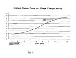
- FIG. 3Implant tissue force versus shape change period curve
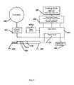
- FIG. 4System diagram based on lookup table
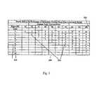
- FIG. 5Lookup table example
- FIG. 6System diagram based on models, algorithms and lookup tables
- FIG. 7Multi-element implant example
- FIG. 8Multi-element implant electrode example
- FIG. 9Electrode handle and system circuit diagram for simple feedback and control system example
- the preferred embodiment of the inventionconsists of an electronic control console that operates using a lookup table, algorithm or mathematical model to control the temperature of a memory alloy implant in such a manner so as to control the extent of its transformation from a martensitic to austenitic microstructure.
- the rate of heat applicationcontrols the rate of implant shape change ( FIG. 1 ). Rapid heating curves ( 100 ) and slow controlled heating curves ( 110 ) both can provide sufficient heat energy to fully convert the material's phase and shape.
- the magnitude of heat transferredcontrols the state-of-the-metal's phase change thus the force exerted on surrounding tissue ( FIG. 2 ). Force and temperature relationships exist for each shape-changing element of an implant. In an implant restrained in bone the force exerted by the implant increases with temperature.
- the tissue forcebegins at or near the austinetic start temperature [A s ] ( 200 ) and increases until the austinetic finish temperature [A f ] ( 210 ) as shown in the implant temperature versus force curve ( FIG. 2 ).
- the forcecan be controlled from a minimum value of the force at body temperature [F min ] ( 220 ) before heating and at body temperature after heating [F max ] ( 230 ).
- the control of the heat energy to the implantis implemented using a device: having a power supply with electrical patient isolation transformer ( 400 ), rectifying circuit to convert alternating to direct current ( 410 ), user controllable timing circuit ( 420 ), user controllable, power circuit ( 430 ), a user operated current delivery electrode ( 440 ), circuit board ( 450 ), bipolar current delivery electrode ( 460 ), heating control button ( 470 ), implant-system continuity light ( 475 ), implant-system, heat energy light ( 480 ), lookup table ( 485 ), front control panel with time, power, on-off switch, and indicator lights ( 490 ), and an audible operational indicator ( 495 ) ( FIG. 4 ).
- the lookup table ( 485 )could be in the form of an alphanumeric table, mathematical model, or algorithm.
- the rate data, time for the implant to close,is used as row ( 510 ) or column ( 520 ) headings and the force is the alternate column heading.
- the voltage setting to achieve the desired implant resultis read from within the cells ( 530 ) of the table.
- the surgeonwill select the implant to be used, maximum level of force for the implant to apply to the surrounding tissue, and the amount of time that the implant should take to change shape.
- Other variablessuch as ambient temperature of the implant, amount of bone movement expected, and extent of shape change when correcting bone angulation can also be input or listed in the lookup table ( 485 ).
- the surgeonAfter review of the lookup table ( 485 ) sets the controls on the front panel of the instrument ( 490 ). After placing the implant into bone the surgeon will bring the electrodes ( 460 ) into contact with the implant. The electrodes ( 460 ) when touching the implant cause the continuity light ( 475 ) to illuminate to show the surgeon that the force and rate control system is in optimal contact with the implant to deliver a user selected amount of heat energy over a user specified period of time. The surgeon then applies heat energy to the implant by actuating the heating control button ( 470 ).
- the continuity light ( 475 )turns off and the heat energy light ( 480 ) illuminates during the user-selected period for heat energy delivery.
- the front panel ( 490 ) time control knobsets the timing circuit ( 420 ) so as to control the rate of heat energy delivery and shape change period.
- Audible current flow indicator ( 495 )assists the surgeon in the use of the system.
- the continuity light ( 475 ) and heat energy light ( 480 )are, located on the electrode handle ( 440 ) so as to be in clear view of the surgeon when working in the operative site.
- the circuit board ( 450 )holds the electrical conductors, user controlled power circuit ( 430 ) and the other components required to complete the system.
- the force magnitude applied to tissueis as listed in the lookup table. If bone transport occurs then the force will be less than predicted. Under this condition the surgeon can measure the amount of bone transport, input these data into the lookup table and correct to obtain the actual applied force. This allows the surgeon to adjust the amount of displacement of bone as well as force exerted on bone during the implantation procedure. This provides fine control for the physician when stabilizing bone elements or fragments.
- the energy light ( 480 )turns off and the cycle is complete.
- the heating energycan be applied multiple times to the implant.
- the surgeonmay sequentially increase the closing force of the implant through stepping the closing force up at 10% to 20% increments until the surgeon receives operative clues that the maximum implant fixation force has been applied without causing fracture of the osteoporotic bone.
- the subject invention for the first timegives full control to the physician to provide a plurality of implant force and closing rate characteristics to each of plurality of implant designs.
- the first alternate embodiment of the inventionis based on the same principals of the preferred embodiment which controls the conversion of the martensitic to austenitic phase transition of the implant material.
- This first alternate embodimentintegrates elements such as but not limited to a lookup table, algorithms, heat transfer models of the implants ( 640 ) and predictive graphics model of the shape change of the implant and force applied to the tissue. These image and numeric data are displayed on the front panel ( 630 ) monitor and controlled using the front panel ( 630 ) keyboard to allow the surgeon to observe the theoretical effects of heating to the implant and adjust the heat energy to the implant to get the desired clinical effect.
- the power supply ( 600 ), AC to DC converter ( 610 ), and circuit board ( 655 )are configured to support a microprocessor ( 650 ) and computer memory which contains model data, model algorithms, and lookup tables ( 640 ) to allow the modeling of the effects of heat energy application to the implant.
- This intelligent system front panel ( 630 )displays implant images, shape change data, and allows the model predictions of the rate and force of implant shape change to be compared to the operative observations.
- the timer relay ( 620 ) and power circuit ( 670 ) in this embodimentare microprocessor ( 650 ) controlled.
- the surgeonwill program the force and rate profile and then using the electrode handle ( 680 ) place the electrodes ( 695 ) on the point of the implant shown on the front panel ( 630 ) monitor to apply heat.
- the electrode start button ( 685 )is pushed, the front panel ( 630 ) monitor then displays the theoretical effect on the implant and directs the surgeon to the next element of the implant for heat energy application.
- This first alternate embodimentallows the surgeon to predict the changes to the implant and then observe the in vivo effects of the implant on bony elements. These features increase the feedback to the surgeon, compensate for and controls heating of multiple elements of an implant and enhances the degree of force and rate control of the implant for the surgeon.
- the surgeonwill select and display the implant on the front panel ( 630 ) monitor. Then the desired rate and tissue force will be input by the surgeon, using the front panel ( 630 ) for each shape-changing element incorporated into the implant. Once set the front panel ( 630 ) monitor will guide the surgeon in using the electrode handle ( 680 ). The monitor will display the point of contact for the electrode ( 695 ) and instruct the surgeon to actuate the electrode start button ( 685 ). The monitor will then display the theoretical shape change and tissue force and guide the surgeon to place the electrode handle ( 680 ) on the next shape-changing member of the implant.
- multiple shape changing membersmay need to be controlled.
- Members that lock into bone ( 720 , 730 , 740 , and 750 ) or shrink to shorten the implant ( 705 and 710 )can be selectively controlled.
- member 720can be affected by applying current to circular points 760 and 765 .
- Member 750can be affected by applying heat energy to points 780 and 785 .
- length shortening or angle changing member 710can be affected by applying heating energy across “x” marked points 770 and 775 .
- a single bipolar electrodecan be used at multiple locations to close each shape-changing member one at a time. Alternatively a multi-electrode handle FIG.
- Electrode handle 880can heat the shape-changing member 720 by having the electrode handle apply current to electrode points 830 and 870 .
- Or member 705 of FIG. 7can be shortened or lengthened by applying heat energy with the handle ( 880 ) and electrodes 840 and 850 .
- the surgeoncan adjust the force applied to the tissue, correct for bone transport that may make the force estimate inaccurate and then instruct the surgeon when the implant is in its final configuration.
- the implant-heating model and lookup tableare replaced with a measurement of the implant temperature.
- This temperature measurementis taken from the surface of the implant.
- Temperature measurement devicesinclude but are not limited to thermocouples and thermal imaging. Other feedback mechanisms such as strain gauges that measure the shape change of the implant can be used for feedback control. These measured data are input to the model or a switch that stops current flow to the implant.
- the system diagram of FIG. 6now takes data from the heat sensing transducers to input into the algorithm and implant models ( 640 ) so that the microprocessor ( 650 ) can correlate force and rate data with temperature and accurately control the implant's shape change.
- This methodaccounts for the environmental temperature issues associated with a cold operating room and a warm patient.
- FIG. 9 system diagramillustrates the temperature feedback embodiment of the invention.
- the power supply ( 900 )is connected to the user-actuated electrode start button ( 910 ) which provides power to a current cutout switch ( 920 ) that receives input from the thermocouple ( 930 ), located on the electrode ( 940 ), through the thermocouple wires ( 960 ).
- the electrode ( 950 )could hold an additional thermocouple for product redundancy and additional points of temperature measurement.
- the amount of power set on the power supply ( 900 )will control the rate of heating and the setting for the cutout switch ( 920 ) is related to the force.
- a lookup tableis used to set the power level and the cutout parameters.
- surgeonselects these two parameters and the system automatically cuts out at the implant temperature corresponding to a specific tissue force.
Landscapes
- Health & Medical Sciences (AREA)
- Life Sciences & Earth Sciences (AREA)
- Surgery (AREA)
- Orthopedic Medicine & Surgery (AREA)
- Engineering & Computer Science (AREA)
- Biomedical Technology (AREA)
- Animal Behavior & Ethology (AREA)
- Veterinary Medicine (AREA)
- Public Health (AREA)
- Heart & Thoracic Surgery (AREA)
- General Health & Medical Sciences (AREA)
- Molecular Biology (AREA)
- Medical Informatics (AREA)
- Nuclear Medicine, Radiotherapy & Molecular Imaging (AREA)
- Vascular Medicine (AREA)
- Neurology (AREA)
- Reproductive Health (AREA)
- Cardiology (AREA)
- Oral & Maxillofacial Surgery (AREA)
- Transplantation (AREA)
- Rheumatology (AREA)
- Prostheses (AREA)
Abstract
Description
- 100 Two second heating curve for martensitic to austinetic phase transformation
- 110 Ten second heating curve for martensitic to austinetic phase transformation
- 200 Austinetic transformation start temperature and inflection in force curve
- 210 Austinetic transformation end temperature
- 220 Minimum tissue force seen at body temperature
- 230 Maximum tissue force seen at body temperature
- 300 Force versus time curve while heating
- 400 Power supply with isolation transformer
- 410 AC to DC power converter
- 420 User set timer circuit
- 430 User set power circuit
- 440 Current delivery electrode
- 450 Circuit board
- 460 Electrode conductor to implant
- 470 Heating control button
- 475 Implant-system continuity
- 480 Implant-system heat energy light
- 485 Lookup table
- 490 Front control panel with time, power, on-off switch, and indicator lights
- 495 Audible operational indicator
- 500 Implant force and rate control lookup table
- 510 Heating duration data
- 520 Force level data
- 530 Power level within cells of the lookup table
- 600 Power supply with isolation transformer
- 610 AC to DC power converter
- 620 Timer circuit
- 630 Front panel control with keyboard and monitor
- 640 Lookup table, model, or algorithm
- 650 Microprocessor running model, algorithm or sorting the lookup table
- 655 Circuit board
- 660 Audible operational indicator
- 670 Power circuit
- 680 Electrode handle
- 685 Electrode start button
- 690 Implant-system continuity light and heat energy light combined
- 695 Electrode conductor to implant
- 700 Spinal plate
- 705 First length or angle shape-changing member
- 710 Second length or angle shape-changing member
- 720 First bone anchoring shape-changing member
- 730 Second bone anchoring shape-changing member
- 740 Third bone anchoring shape-changing member
- 750 Fourth bone anchoring shape-changing member
- 760 First electrode contact point for
member 720 - 765 Second electrode contact point for
member 720 - 770 First electrode contact point for
member 710 - 775 Second electrode contact point for
member 710 - 780 First electrode contact point for
member 750 - 785 Second electrode contact point for
member 750 - 800 First electrode element for
FIG. 7 member 720 - 810 First electrode element for
FIG. 7 member 730 - 820 First electrode element for
FIG. 7 member 740 - 830 First electrode element for
FIG. 7 member 750 - 840 Second electrode element for
FIG. 7 member 740 - 850 Second electrode element for
FIG. 7 member 730 - 860 Second electrode element for
FIG. 7 member 720 - 870 Second electrode element for
FIG. 7 member 750 - 880 Multi-electrode handle
- 890 Electrode conductor bundle
- 895 Individual electrode conductors
- 900 Power supply
- 910 User operated switch
- 920 Temperature cutout switch
- 930 Thermocouple temperature sensing transducer
- 940 Implant heating electrode with thermocouple
- 950 Implant heating electrode
- 960 Thermocouple leads to temperature cutout switch
Claims (61)
Priority Applications (4)
| Application Number | Priority Date | Filing Date | Title |
|---|---|---|---|
| US10/356,830US7240677B2 (en) | 2003-02-03 | 2003-02-03 | System and method for force, displacement, and rate control of shaped memory material implants |
| US11/804,294US20070265631A1 (en) | 2003-02-03 | 2007-05-17 | System and method for force, displacement, and rate control of shaped memory material implants |
| US15/179,730US20160278825A1 (en) | 2003-02-03 | 2016-06-10 | Force, displacement, and rate controlled shaped memory material implants |
| US16/102,240US10695114B2 (en) | 2003-02-03 | 2018-08-13 | Method for force, displacement, and rate control of shaped memory material implants |
Applications Claiming Priority (1)
| Application Number | Priority Date | Filing Date | Title |
|---|---|---|---|
| US10/356,830US7240677B2 (en) | 2003-02-03 | 2003-02-03 | System and method for force, displacement, and rate control of shaped memory material implants |
Related Child Applications (1)
| Application Number | Title | Priority Date | Filing Date |
|---|---|---|---|
| US11/804,294DivisionUS20070265631A1 (en) | 2003-02-03 | 2007-05-17 | System and method for force, displacement, and rate control of shaped memory material implants |
Publications (2)
| Publication Number | Publication Date |
|---|---|
| US20040172107A1 US20040172107A1 (en) | 2004-09-02 |
| US7240677B2true US7240677B2 (en) | 2007-07-10 |
Family
ID=32907596
Family Applications (4)
| Application Number | Title | Priority Date | Filing Date |
|---|---|---|---|
| US10/356,830Expired - LifetimeUS7240677B2 (en) | 2003-02-03 | 2003-02-03 | System and method for force, displacement, and rate control of shaped memory material implants |
| US11/804,294AbandonedUS20070265631A1 (en) | 2003-02-03 | 2007-05-17 | System and method for force, displacement, and rate control of shaped memory material implants |
| US15/179,730AbandonedUS20160278825A1 (en) | 2003-02-03 | 2016-06-10 | Force, displacement, and rate controlled shaped memory material implants |
| US16/102,240Expired - LifetimeUS10695114B2 (en) | 2003-02-03 | 2018-08-13 | Method for force, displacement, and rate control of shaped memory material implants |
Family Applications After (3)
| Application Number | Title | Priority Date | Filing Date |
|---|---|---|---|
| US11/804,294AbandonedUS20070265631A1 (en) | 2003-02-03 | 2007-05-17 | System and method for force, displacement, and rate control of shaped memory material implants |
| US15/179,730AbandonedUS20160278825A1 (en) | 2003-02-03 | 2016-06-10 | Force, displacement, and rate controlled shaped memory material implants |
| US16/102,240Expired - LifetimeUS10695114B2 (en) | 2003-02-03 | 2018-08-13 | Method for force, displacement, and rate control of shaped memory material implants |
Country Status (1)
| Country | Link |
|---|---|
| US (4) | US7240677B2 (en) |
Cited By (41)
| Publication number | Priority date | Publication date | Assignee | Title |
|---|---|---|---|---|
| US20080177262A1 (en)* | 2005-04-14 | 2008-07-24 | Marc Augoyard | Intramedullar Osteosynthetic Device of Two Bone Parts, In Particular of the Hand and/or Foot |
| US20080262629A1 (en)* | 2007-03-26 | 2008-10-23 | Fonte Matthew V | Proximally Self-Locking Long Bone Prosthesis |
| US20100131014A1 (en)* | 2007-03-20 | 2010-05-27 | Memometal Technologies | Osteosynthesis device |
| US20110137347A1 (en)* | 2009-12-01 | 2011-06-09 | Synthes Usa, Llc | Non-fusion scoliosis expandable spinal rod |
| US20110144644A1 (en)* | 2008-09-09 | 2011-06-16 | Memometal Technologies | Resorptive intramedullary implant between two bones or two bone fragments |
| WO2013016633A1 (en) | 2011-07-27 | 2013-01-31 | William Casey Fox | Bone staple, instrument and method of use and manufacturing |
| WO2013055824A1 (en) | 2011-10-10 | 2013-04-18 | William Casey Fox | Shape changing bone implant for enhanced healing |
| WO2014120955A1 (en) | 2013-01-31 | 2014-08-07 | William Casey Fox | Bone staple extrusion instrument and method of use and manufacturing |
| US8915916B2 (en) | 2008-05-05 | 2014-12-23 | Mayo Foundation For Medical Education And Research | Intramedullary fixation device for small bone fractures |
| US8961567B2 (en) | 2010-11-22 | 2015-02-24 | DePuy Synthes Products, LLC | Non-fusion scoliosis expandable spinal rod |
| US9095338B2 (en) | 2012-10-09 | 2015-08-04 | Wright Medical Technology, Inc. | Surgical staple insertion device |
| US9101349B2 (en) | 2012-02-16 | 2015-08-11 | Biomedical Enterprises, Inc. | Apparatus for an orthopedic fixation system |
| US20160278825A1 (en)* | 2003-02-03 | 2016-09-29 | William Casey Fox | Force, displacement, and rate controlled shaped memory material implants |
| US9474561B2 (en) | 2013-11-19 | 2016-10-25 | Wright Medical Technology, Inc. | Two-wire technique for installing hammertoe implant |
| US9498273B2 (en) | 2010-06-02 | 2016-11-22 | Wright Medical Technology, Inc. | Orthopedic implant kit |
| US9498266B2 (en) | 2014-02-12 | 2016-11-22 | Wright Medical Technology, Inc. | Intramedullary implant, system, and method for inserting an implant into a bone |
| US9504582B2 (en) | 2012-12-31 | 2016-11-29 | Wright Medical Technology, Inc. | Ball and socket implants for correction of hammer toes and claw toes |
| US9545274B2 (en) | 2014-02-12 | 2017-01-17 | Wright Medical Technology, Inc. | Intramedullary implant, system, and method for inserting an implant into a bone |
| US9585656B2 (en) | 2013-06-03 | 2017-03-07 | Biomedical Enterprises, Inc. | Method and apparatus for loading and implanting a shape memory implant |
| US9603643B2 (en) | 2010-06-02 | 2017-03-28 | Wright Medical Technology, Inc. | Hammer toe implant with expansion portion for retrograde approach |
| US9724139B2 (en) | 2013-10-01 | 2017-08-08 | Wright Medical Technology, Inc. | Hammer toe implant and method |
| US9724140B2 (en) | 2010-06-02 | 2017-08-08 | Wright Medical Technology, Inc. | Tapered, cylindrical cruciform hammer toe implant and method |
| US9757168B2 (en) | 2015-03-03 | 2017-09-12 | Howmedica Osteonics Corp. | Orthopedic implant and methods of implanting and removing same |
| US9808296B2 (en) | 2014-09-18 | 2017-11-07 | Wright Medical Technology, Inc. | Hammertoe implant and instrument |
| US9907551B2 (en) | 2014-08-04 | 2018-03-06 | Howmedica Osteonics Corp. | Surgical instrument for implanting fixation device |
| US10080597B2 (en) | 2014-12-19 | 2018-09-25 | Wright Medical Technology, Inc. | Intramedullary anchor for interphalangeal arthrodesis |
| US10117647B2 (en) | 2015-09-03 | 2018-11-06 | Biomedical Enterprises, Inc | Elastic orthopedic implant and method of manufacturing thereof |
| US10456131B2 (en) | 2014-05-07 | 2019-10-29 | Biomedical Enterprises, Inc. | Method and apparatus for loading and implanting a shape memory implant |
| US10456130B2 (en) | 2014-05-07 | 2019-10-29 | Biomedical Enterprises, Inc. | Method and apparatus for loading and implanting a shape memory implant |
| US10470807B2 (en) | 2016-06-03 | 2019-11-12 | Stryker European Holdings I, Llc | Intramedullary implant and method of use |
| USD870284S1 (en) | 2017-07-31 | 2019-12-17 | Crossroads Extremity Systems, Llc | Osteosynthesis clip |
| US10842487B2 (en) | 2017-10-20 | 2020-11-24 | Biomedical Enterprises, Inc. | Method and apparatus for loading and implanting a shape memory implant |
| US20210267644A1 (en)* | 2020-03-02 | 2021-09-02 | Cleveland State University | Metal plate with one-way shape memory effect |
| US11524153B2 (en) | 2016-10-03 | 2022-12-13 | Queen Mary University Of London | Mechanical circulatory support device with axial flow turbomachine optimized for heart failure and cardio-renal syndrome by implantation in the descending aorta |
| US11523820B2 (en) | 2020-01-29 | 2022-12-13 | DePuy Synthes Products, Inc. | Shape memory implants and a method and apparatus for the loading and implanting thereof |
| US11679250B2 (en) | 2019-06-28 | 2023-06-20 | Theodosios Alexander | Removable mechanical circulatory support for short term use |
| US11813445B2 (en) | 2012-11-06 | 2023-11-14 | Queen Mary University Of London | Mechanical circulatory support device with centrifugal impeller designed for implantation in the descending aorta |
| US12042386B2 (en) | 2020-01-29 | 2024-07-23 | DePuy Synthes Products, Inc. | Shape memory implants and methods and apparatus for the loading and implanting thereof |
| US12053624B2 (en) | 2018-04-04 | 2024-08-06 | Theodosios Alexander | Removable mechanical circulatory support for short term use |
| US12090310B2 (en) | 2016-10-03 | 2024-09-17 | Procardia Llc | Mechanical circulatory support device with axial flow turbomachine optimized for heart failure and cardio-renal syndrome by implantation in the descending aorta |
| US12151092B2 (en) | 2012-11-06 | 2024-11-26 | Procardia Llc | Mechanical circulatory support device with centrifugal impeller designed for implantation in the descending aorta |
Families Citing this family (30)
| Publication number | Priority date | Publication date | Assignee | Title |
|---|---|---|---|---|
| US20070088412A1 (en)* | 2005-10-13 | 2007-04-19 | Intelifuse, Inc., A Corporation Of The State Of Delaware | System and device for heating or cooling shape memory surgical devices |
| US20070173855A1 (en)* | 2006-01-17 | 2007-07-26 | Sdgi Holdings, Inc. | Devices and methods for spacing of vertebral members over multiple levels |
| US20090218321A1 (en)* | 2006-02-14 | 2009-09-03 | Intelifuse, Inc. | Shape Memory Implant Heating Device |
| US9039768B2 (en) | 2006-12-22 | 2015-05-26 | Medos International Sarl | Composite vertebral spacers and instrument |
| US20090248092A1 (en) | 2008-03-26 | 2009-10-01 | Jonathan Bellas | Posterior Intervertebral Disc Inserter and Expansion Techniques |
| US9526620B2 (en) | 2009-03-30 | 2016-12-27 | DePuy Synthes Products, Inc. | Zero profile spinal fusion cage |
| US9393129B2 (en) | 2009-12-10 | 2016-07-19 | DePuy Synthes Products, Inc. | Bellows-like expandable interbody fusion cage |
| US20120078372A1 (en) | 2010-09-23 | 2012-03-29 | Thomas Gamache | Novel implant inserter having a laterally-extending dovetail engagement feature |
| US11529241B2 (en) | 2010-09-23 | 2022-12-20 | DePuy Synthes Products, Inc. | Fusion cage with in-line single piece fixation |
| US20120078373A1 (en) | 2010-09-23 | 2012-03-29 | Thomas Gamache | Stand alone intervertebral fusion device |
| WO2012058448A2 (en) | 2010-10-27 | 2012-05-03 | Toby Orthopaedics, Llc | System and method for fracture replacement of comminuted bone fractures or portions thereof adjacent bone joints |
| US20120226321A1 (en)* | 2011-03-03 | 2012-09-06 | Eduardo Gonzalez-Hernandez | Modular and non-modular cortical buttress device |
| US9248028B2 (en) | 2011-09-16 | 2016-02-02 | DePuy Synthes Products, Inc. | Removable, bone-securing cover plate for intervertebral fusion cage |
| US9271772B2 (en) | 2011-10-27 | 2016-03-01 | Toby Orthopaedics, Inc. | System and method for fracture replacement of comminuted bone fractures or portions thereof adjacent bone joints |
| US9730797B2 (en) | 2011-10-27 | 2017-08-15 | Toby Orthopaedics, Inc. | Bone joint replacement and repair assembly and method of repairing and replacing a bone joint |
| US9402667B2 (en) | 2011-11-09 | 2016-08-02 | Eduardo Gonzalez-Hernandez | Apparatus and method for use of the apparatus for fracture fixation of the distal humerus |
| US9271836B2 (en) | 2012-03-06 | 2016-03-01 | DePuy Synthes Products, Inc. | Nubbed plate |
| US10182921B2 (en) | 2012-11-09 | 2019-01-22 | DePuy Synthes Products, Inc. | Interbody device with opening to allow packing graft and other biologics |
| US9283008B2 (en) | 2012-12-17 | 2016-03-15 | Toby Orthopaedics, Inc. | Bone plate for plate osteosynthesis and method for use thereof |
| US9974673B2 (en)* | 2013-01-18 | 2018-05-22 | Memory Effect Medical, LLC | System for deploying an inductive shape memory catheterization device and methods for use therewith |
| CN106102612B (en) | 2013-11-11 | 2020-07-21 | 阿特雷克斯公司 | Screw for generating and applying compression in the body |
| EP3068325B1 (en) | 2013-11-13 | 2021-09-15 | Arthrex, Inc. | Intermedullary devices for generating and applying compression within a body |
| WO2016123382A1 (en) | 2015-01-28 | 2016-08-04 | Mx Orthopedics, Corp. | Self-compressing screws for generating and applying compression within a body |
| WO2016154417A1 (en) | 2015-03-24 | 2016-09-29 | Mẍ Orthopedics, Corp. | Staples for generating and applying compression within a body |
| US10940016B2 (en) | 2017-07-05 | 2021-03-09 | Medos International Sarl | Expandable intervertebral fusion cage |
| US12213662B2 (en) | 2017-11-14 | 2025-02-04 | Intuitive Surgical Operations, Inc. | Electrically weldable suture material, and apparatus and method for forming welded suture loops and other welded structures |
| EP3709931B1 (en)* | 2017-11-14 | 2024-10-16 | Egan Design LLC | Electrically weldable suture material |
| US12114853B2 (en) | 2017-11-14 | 2024-10-15 | Intuitive Surgical Operations, Inc. | Electrically weldable suture material, and apparatus and method for forming welded suture loops and other welded structures |
| EP3998999A4 (en) | 2019-07-16 | 2023-08-16 | Microvention, Inc. | MEDICAL DEVICE WITH IMPROVED FORM PROPERTIES |
| CN118384325B (en)* | 2024-05-09 | 2025-01-17 | 吉林大学 | A preparation method for 4D printed intelligent near-infrared responsive bone filling implant |
Citations (12)
| Publication number | Priority date | Publication date | Assignee | Title |
|---|---|---|---|---|
| US3174851A (en) | 1961-12-01 | 1965-03-23 | William J Buehler | Nickel-base alloys |
| US3868956A (en) | 1972-06-05 | 1975-03-04 | Ralph J Alfidi | Vessel implantable appliance and method of implanting it |
| US4485816A (en) | 1981-06-25 | 1984-12-04 | Alchemia | Shape-memory surgical staple apparatus and method for use in surgical suturing |
| US4550870A (en) | 1983-10-13 | 1985-11-05 | Alchemia Ltd. Partnership | Stapling device |
| US4665906A (en) | 1983-10-14 | 1987-05-19 | Raychem Corporation | Medical devices incorporating sim alloy elements |
| US5067957A (en) | 1983-10-14 | 1991-11-26 | Raychem Corporation | Method of inserting medical devices incorporating SIM alloy elements |
| US5190546A (en) | 1983-10-14 | 1993-03-02 | Raychem Corporation | Medical devices incorporating SIM alloy elements |
| US5290289A (en) | 1990-05-22 | 1994-03-01 | Sanders Albert E | Nitinol spinal instrumentation and method for surgically treating scoliosis |
| US6268589B1 (en) | 1998-05-15 | 2001-07-31 | M.B.A., S.A. | Controller and sterilizable head for a device for heating clips with shape memory |
| US6543224B1 (en)* | 2002-01-29 | 2003-04-08 | United Technologies Corporation | System and method for controlling shape memory alloy actuators |
| US6633095B1 (en)* | 1999-03-01 | 2003-10-14 | Charles B. Swope | Motion device using shape memory material and method therefor |
| US6671547B2 (en)* | 2001-06-13 | 2003-12-30 | Koninklijke Philips Electronics N.V. | Adaptive analysis method for an electrotherapy device and apparatus |
Family Cites Families (29)
| Publication number | Priority date | Publication date | Assignee | Title |
|---|---|---|---|---|
| US3786806A (en)* | 1972-11-22 | 1974-01-22 | A Johnson | Thermoconstrictive surgical appliance |
| US3786814A (en)* | 1972-12-15 | 1974-01-22 | T Armao | Method of preventing cryoadhesion of cryosurgical instruments and cryosurgical instruments |
| GB1551705A (en)* | 1975-04-28 | 1979-08-30 | Downs Surgicial Ltd | Surgial implant |
| US4170990A (en)* | 1977-01-28 | 1979-10-16 | Fried. Krupp Gesellschaft Mit Beschrankter Haftung | Method for implanting and subsequently removing mechanical connecting elements from living tissue |
| US5002563A (en)* | 1990-02-22 | 1991-03-26 | Raychem Corporation | Sutures utilizing shape memory alloys |
| FR2668361A1 (en)* | 1990-10-30 | 1992-04-30 | Mai Christian | OSTEOSYNTHESIS CLIP AND PLATE WITH SELF-RETENTIVE DYNAMIC COMPRESSION. |
| DK168419B1 (en)* | 1991-11-25 | 1994-03-28 | Cook Inc A Cook Group Company | Abdominal wall support device and apparatus for insertion thereof |
| FR2700464B1 (en)* | 1992-11-13 | 1995-04-14 | Maurice Bertholet | Connecting piece for bone elements. |
| US5543678A (en)* | 1993-05-11 | 1996-08-06 | Hoiberg; Dane A. | Flat motors |
| FR2710254B1 (en)* | 1993-09-21 | 1995-10-27 | Mai Christian | Multi-branch osteosynthesis clip with self-retaining dynamic compression. |
| US5617854A (en)* | 1994-06-22 | 1997-04-08 | Munsif; Anand | Shaped catheter device and method |
| US5904697A (en)* | 1995-02-24 | 1999-05-18 | Heartport, Inc. | Devices and methods for performing a vascular anastomosis |
| FR2754702B1 (en)* | 1996-10-18 | 1999-01-08 | Medinov Amp | DEVICE FOR SOLIDARIZING AT LEAST TWO VERTEBRAL BODIES |
| US6024764A (en)* | 1997-08-19 | 2000-02-15 | Intermedics, Inc. | Apparatus for imparting physician-determined shapes to implantable tubular devices |
| US5964770A (en)* | 1997-09-30 | 1999-10-12 | Litana Ltd. | High strength medical devices of shape memory alloy |
| US5989268A (en)* | 1997-10-28 | 1999-11-23 | Boston Scientific Corporation | Endoscopic hemostatic clipping device |
| US6063111A (en)* | 1998-03-31 | 2000-05-16 | Cordis Corporation | Stent aneurysm treatment system and method |
| US6200330B1 (en)* | 1998-11-23 | 2001-03-13 | Theodore V. Benderev | Systems for securing sutures, grafts and soft tissue to bone and periosteum |
| US8118822B2 (en)* | 1999-03-01 | 2012-02-21 | Medtronic, Inc. | Bridge clip tissue connector apparatus and methods |
| US6325805B1 (en)* | 1999-04-23 | 2001-12-04 | Sdgi Holdings, Inc. | Shape memory alloy staple |
| US6299613B1 (en)* | 1999-04-23 | 2001-10-09 | Sdgi Holdings, Inc. | Method for the correction of spinal deformities through vertebral body tethering without fusion |
| US6494889B1 (en)* | 1999-09-01 | 2002-12-17 | Converge Medical, Inc. | Additional sutureless anastomosis embodiments |
| US6405532B1 (en)* | 2000-07-21 | 2002-06-18 | Environmental Robots, Inc. | Metal hydride artificial muscles |
| US6322580B1 (en)* | 2000-09-01 | 2001-11-27 | Angiolink Corporation | Wound site management and wound closure device |
| IL138320A (en)* | 2000-09-07 | 2005-11-20 | Niti Alloys Tech Ltd | Staples for bone fixation |
| EP1437989A2 (en)* | 2001-08-27 | 2004-07-21 | James C. Thomas, Jr. | Expandable implant for partial disc replacement and reinforcement of a disc partially removed in a discectomy and for reduction and maintenance of alignment of cancellous bone fractures and methods and apparatuses for same. |
| US7240677B2 (en)* | 2003-02-03 | 2007-07-10 | Biomedical Enterprises, Inc. | System and method for force, displacement, and rate control of shaped memory material implants |
| US20050085925A1 (en)* | 2003-10-16 | 2005-04-21 | Mohsen Shahinpoor | Bio-Potential Activation of Artificial Muscles |
| WO2017011589A1 (en)* | 2015-07-13 | 2017-01-19 | Crossroads Extremity Systems, Llc | Bone plates with dynamic elements |
- 2003
- 2003-02-03USUS10/356,830patent/US7240677B2/ennot_activeExpired - Lifetime
- 2007
- 2007-05-17USUS11/804,294patent/US20070265631A1/ennot_activeAbandoned
- 2016
- 2016-06-10USUS15/179,730patent/US20160278825A1/ennot_activeAbandoned
- 2018
- 2018-08-13USUS16/102,240patent/US10695114B2/ennot_activeExpired - Lifetime
Patent Citations (13)
| Publication number | Priority date | Publication date | Assignee | Title |
|---|---|---|---|---|
| US3174851A (en) | 1961-12-01 | 1965-03-23 | William J Buehler | Nickel-base alloys |
| US3868956A (en) | 1972-06-05 | 1975-03-04 | Ralph J Alfidi | Vessel implantable appliance and method of implanting it |
| US4485816A (en) | 1981-06-25 | 1984-12-04 | Alchemia | Shape-memory surgical staple apparatus and method for use in surgical suturing |
| US4550870A (en) | 1983-10-13 | 1985-11-05 | Alchemia Ltd. Partnership | Stapling device |
| US5190546A (en) | 1983-10-14 | 1993-03-02 | Raychem Corporation | Medical devices incorporating SIM alloy elements |
| US5067957A (en) | 1983-10-14 | 1991-11-26 | Raychem Corporation | Method of inserting medical devices incorporating SIM alloy elements |
| US4665906A (en) | 1983-10-14 | 1987-05-19 | Raychem Corporation | Medical devices incorporating sim alloy elements |
| US5290289A (en) | 1990-05-22 | 1994-03-01 | Sanders Albert E | Nitinol spinal instrumentation and method for surgically treating scoliosis |
| US6268589B1 (en) | 1998-05-15 | 2001-07-31 | M.B.A., S.A. | Controller and sterilizable head for a device for heating clips with shape memory |
| US6323461B2 (en) | 1998-05-15 | 2001-11-27 | M.B.A., S.A. | Clamps with shape memory |
| US6633095B1 (en)* | 1999-03-01 | 2003-10-14 | Charles B. Swope | Motion device using shape memory material and method therefor |
| US6671547B2 (en)* | 2001-06-13 | 2003-12-30 | Koninklijke Philips Electronics N.V. | Adaptive analysis method for an electrotherapy device and apparatus |
| US6543224B1 (en)* | 2002-01-29 | 2003-04-08 | United Technologies Corporation | System and method for controlling shape memory alloy actuators |
Non-Patent Citations (3)
| Title |
|---|
| Beynet et al. "The Modeling of a Shape Memory Alloy Microplate," 1996. |
| Beynet. "An Account of the Mechanical Experiments on Surgical Staples," Mar. 1994. |
| Beynet. "Production of a Fracture-Reducing Staple Using TiNi Shape-Memory Alloys," 1994. (End of Studies Thesis). |
Cited By (99)
| Publication number | Priority date | Publication date | Assignee | Title |
|---|---|---|---|---|
| US20160278825A1 (en)* | 2003-02-03 | 2016-09-29 | William Casey Fox | Force, displacement, and rate controlled shaped memory material implants |
| US10695114B2 (en)* | 2003-02-03 | 2020-06-30 | William Casey Fox | Method for force, displacement, and rate control of shaped memory material implants |
| US8475456B2 (en) | 2005-04-14 | 2013-07-02 | Memometal Technologies | Intramedullar osteosynthetic device of two bone parts, in particular of the hand and/or foot |
| US20080177262A1 (en)* | 2005-04-14 | 2008-07-24 | Marc Augoyard | Intramedullar Osteosynthetic Device of Two Bone Parts, In Particular of the Hand and/or Foot |
| US9492215B2 (en) | 2005-04-14 | 2016-11-15 | Stryker European Holdings I, Llc | Method of osteosyntheses or arthrodeses of two- bone parts, in particular of the hand and / or foot |
| US11006984B2 (en) | 2005-04-14 | 2021-05-18 | Stryker European Operations Holdings Llc | Device for osteosyntheses or arthrodesis of two-bone parts, in particular of the hand and / or foot |
| US11478285B2 (en) | 2005-04-14 | 2022-10-25 | Stryker European Operations Holdings Llc | Device for osteosyntheses or arthrodesis of two-bone parts, in particular of the hand and/or foot |
| US10022167B2 (en) | 2005-04-14 | 2018-07-17 | Stryker European Holdings I, Llc | Method of osteosyntheses or arthrodesis of two-bone parts, in particular of the hand and / or foot |
| US9283007B2 (en) | 2005-04-14 | 2016-03-15 | Stryker European Holdings I, Llc | Device for osteosyntheses or arthrodeses of two- bone parts, in particular of the hand and / or foot |
| US9161789B2 (en) | 2007-03-20 | 2015-10-20 | Memometal Technologies | Osteosynthesis device |
| US10912594B2 (en) | 2007-03-20 | 2021-02-09 | Stryker European Holdings I, Llc | Osteosynthesis device |
| US20100131014A1 (en)* | 2007-03-20 | 2010-05-27 | Memometal Technologies | Osteosynthesis device |
| US12396766B2 (en) | 2007-03-20 | 2025-08-26 | Stryker European Operations Holdings Llc | Osteosynthesis device |
| US8394097B2 (en) | 2007-03-20 | 2013-03-12 | Memometal Technologies | Osteosynthesis device |
| US9839453B2 (en) | 2007-03-20 | 2017-12-12 | Stryker European Holdings I, Llc | Osteosynthesis device |
| US8062378B2 (en) | 2007-03-26 | 2011-11-22 | Mx Orthopedics Corp. | Proximal self-locking long bone prosthesis |
| US20090204226A1 (en)* | 2007-03-26 | 2009-08-13 | Mx Orthopedics Corp. | Proximally Self-Locking Long Bone Prosthesis |
| US20080262629A1 (en)* | 2007-03-26 | 2008-10-23 | Fonte Matthew V | Proximally Self-Locking Long Bone Prosthesis |
| US8398790B2 (en) | 2007-03-26 | 2013-03-19 | Mx Orthopedics, Corp. | Proximally self-locking long bone prosthesis |
| US8137486B2 (en) | 2007-03-26 | 2012-03-20 | Mx Orthopedics, Corp. | Proximally self-locking long bone prosthesis |
| US20110192563A1 (en)* | 2007-03-26 | 2011-08-11 | Mx Orthopedics Corp. | Proximally Self-Locking Long Bone Prosthesis |
| US7947135B2 (en) | 2007-03-26 | 2011-05-24 | Mx Orthopedics Corp. | Proximally self-locking long bone prosthesis |
| US8915916B2 (en) | 2008-05-05 | 2014-12-23 | Mayo Foundation For Medical Education And Research | Intramedullary fixation device for small bone fractures |
| US9168074B2 (en) | 2008-09-09 | 2015-10-27 | Memometal Technologies | Resorptive intramedullary implant between two bones or two bone fragments |
| US12059186B2 (en) | 2008-09-09 | 2024-08-13 | Stryker European Operations Holdings Llc | Resorptive intramedullary implant between two bones or two bone fragments |
| US12383319B2 (en) | 2008-09-09 | 2025-08-12 | Stryker European Operations Holdings Llc | Resorptive intramedullary implant between two bones or two bone fragments |
| US10383671B2 (en) | 2008-09-09 | 2019-08-20 | Stryker European Holdings I, Llc | Resorptive intramedullary implant between two bones or two bone fragments |
| US12390255B2 (en) | 2008-09-09 | 2025-08-19 | Stryker European Operations Holdings Llc | Resorptive intramedullary implant between two bones or two bone fragments |
| US8414583B2 (en) | 2008-09-09 | 2013-04-09 | Memometal Technologies | Resorptive intramedullary implant between two bones or two bone fragments |
| US20110144644A1 (en)* | 2008-09-09 | 2011-06-16 | Memometal Technologies | Resorptive intramedullary implant between two bones or two bone fragments |
| US8568457B2 (en) | 2009-12-01 | 2013-10-29 | DePuy Synthes Products, LLC | Non-fusion scoliosis expandable spinal rod |
| US9282997B2 (en) | 2009-12-01 | 2016-03-15 | DePuy Synthes Products, Inc. | Non-fusion scoliosis expandable spinal rod |
| US10548638B2 (en) | 2009-12-01 | 2020-02-04 | DePuy Synthes Products, Inc. | Non-fusion scoliosis expandable spinal rod |
| US20110137347A1 (en)* | 2009-12-01 | 2011-06-09 | Synthes Usa, Llc | Non-fusion scoliosis expandable spinal rod |
| US9877753B2 (en) | 2010-06-02 | 2018-01-30 | Wright Medical Technology, Inc. | Orthopedic implant kit |
| US10736676B2 (en) | 2010-06-02 | 2020-08-11 | Wright Medical Technology, Inc. | Orthopedic implant kit |
| US9603643B2 (en) | 2010-06-02 | 2017-03-28 | Wright Medical Technology, Inc. | Hammer toe implant with expansion portion for retrograde approach |
| US9949775B2 (en) | 2010-06-02 | 2018-04-24 | Wright Medical Technology, Inc. | Hammer toe implant with expansion portion for retrograde approach |
| US9498273B2 (en) | 2010-06-02 | 2016-11-22 | Wright Medical Technology, Inc. | Orthopedic implant kit |
| US9724140B2 (en) | 2010-06-02 | 2017-08-08 | Wright Medical Technology, Inc. | Tapered, cylindrical cruciform hammer toe implant and method |
| US9861390B2 (en) | 2010-11-22 | 2018-01-09 | DePuy Synthes Products, Inc. | Non-fusion scoliosis expandable spinal rod |
| US11660124B2 (en) | 2010-11-22 | 2023-05-30 | DePuy Synthes Products, Inc. | Non-fusion scoliosis expandable spinal rod |
| US8961567B2 (en) | 2010-11-22 | 2015-02-24 | DePuy Synthes Products, LLC | Non-fusion scoliosis expandable spinal rod |
| US10507042B2 (en) | 2010-11-22 | 2019-12-17 | DePuy Synthes Products, Inc. | Non-fusion scoliosis expandable spinal rod |
| US9339268B2 (en) | 2011-07-27 | 2016-05-17 | William Casey Fox | Bone staple, instrument and method of use and manufacturing |
| US9451957B2 (en) | 2011-07-27 | 2016-09-27 | William Casey Fox | Bone staple extrusion instrument and method of use and manufacturing |
| US9017331B2 (en) | 2011-07-27 | 2015-04-28 | William Casey Fox | Bone staple, instrument and method of use and manufacturing |
| US10512459B2 (en) | 2011-07-27 | 2019-12-24 | William Casey Fox | Bone staple, instrument and method of use and manufacturing |
| US9743926B2 (en) | 2011-07-27 | 2017-08-29 | William Casey Fox | Bone staple, instrument and method of use and manufacturing |
| WO2013016633A1 (en) | 2011-07-27 | 2013-01-31 | William Casey Fox | Bone staple, instrument and method of use and manufacturing |
| WO2013055824A1 (en) | 2011-10-10 | 2013-04-18 | William Casey Fox | Shape changing bone implant for enhanced healing |
| USRE49667E1 (en) | 2011-10-10 | 2023-09-26 | William Casey Fox | Shape changing bone implant and method of use for enhancing healing |
| US10448979B2 (en) | 2011-10-10 | 2019-10-22 | William Casey Fox | Shape changing bone implant and method of use for enhancing healing |
| US9204932B2 (en) | 2012-02-16 | 2015-12-08 | Biomedical Enterprises, Inc. | Apparatus for an orthopedic fixation system |
| US9101349B2 (en) | 2012-02-16 | 2015-08-11 | Biomedical Enterprises, Inc. | Apparatus for an orthopedic fixation system |
| US9724146B2 (en) | 2012-02-16 | 2017-08-08 | Biomedical Enterprises, Inc. | Method and apparatus for an orthopedic fixation system |
| US11090095B2 (en) | 2012-02-16 | 2021-08-17 | Biomedical Enterprises, Inc. | Method and apparatus for an orthopedic fixation system |
| US9700362B2 (en) | 2012-02-16 | 2017-07-11 | Biomedical Enterprises, Inc. | Method and apparatus for an orthopedic fixation system |
| US9095338B2 (en) | 2012-10-09 | 2015-08-04 | Wright Medical Technology, Inc. | Surgical staple insertion device |
| US11813445B2 (en) | 2012-11-06 | 2023-11-14 | Queen Mary University Of London | Mechanical circulatory support device with centrifugal impeller designed for implantation in the descending aorta |
| US12151092B2 (en) | 2012-11-06 | 2024-11-26 | Procardia Llc | Mechanical circulatory support device with centrifugal impeller designed for implantation in the descending aorta |
| US10278828B2 (en) | 2012-12-31 | 2019-05-07 | Wright Medical Technology, Inc. | Ball and socket implants for correction of hammer toes and claw toes |
| US9504582B2 (en) | 2012-12-31 | 2016-11-29 | Wright Medical Technology, Inc. | Ball and socket implants for correction of hammer toes and claw toes |
| WO2014120955A1 (en) | 2013-01-31 | 2014-08-07 | William Casey Fox | Bone staple extrusion instrument and method of use and manufacturing |
| US9585656B2 (en) | 2013-06-03 | 2017-03-07 | Biomedical Enterprises, Inc. | Method and apparatus for loading and implanting a shape memory implant |
| US9724139B2 (en) | 2013-10-01 | 2017-08-08 | Wright Medical Technology, Inc. | Hammer toe implant and method |
| US9675392B2 (en) | 2013-11-19 | 2017-06-13 | Wright Medical Technology, Inc. | Two-wire technique for installing hammertoe implant |
| US9474561B2 (en) | 2013-11-19 | 2016-10-25 | Wright Medical Technology, Inc. | Two-wire technique for installing hammertoe implant |
| US9498266B2 (en) | 2014-02-12 | 2016-11-22 | Wright Medical Technology, Inc. | Intramedullary implant, system, and method for inserting an implant into a bone |
| US9545274B2 (en) | 2014-02-12 | 2017-01-17 | Wright Medical Technology, Inc. | Intramedullary implant, system, and method for inserting an implant into a bone |
| US10456130B2 (en) | 2014-05-07 | 2019-10-29 | Biomedical Enterprises, Inc. | Method and apparatus for loading and implanting a shape memory implant |
| US10849618B2 (en) | 2014-05-07 | 2020-12-01 | Biomedical Enterprises, Inc. | Method and apparatus for loading and implanting a shape memory implant |
| US10888315B2 (en) | 2014-05-07 | 2021-01-12 | Biomedical Enterprises, Inc. | Method and apparatus for loading and implanting a shape memory implant |
| US10456131B2 (en) | 2014-05-07 | 2019-10-29 | Biomedical Enterprises, Inc. | Method and apparatus for loading and implanting a shape memory implant |
| US9907551B2 (en) | 2014-08-04 | 2018-03-06 | Howmedica Osteonics Corp. | Surgical instrument for implanting fixation device |
| US10299840B2 (en) | 2014-09-18 | 2019-05-28 | Wright Medical Technology, Inc. | Hammertoe implant and instrument |
| US9808296B2 (en) | 2014-09-18 | 2017-11-07 | Wright Medical Technology, Inc. | Hammertoe implant and instrument |
| US10080597B2 (en) | 2014-12-19 | 2018-09-25 | Wright Medical Technology, Inc. | Intramedullary anchor for interphalangeal arthrodesis |
| US10702318B2 (en) | 2015-03-03 | 2020-07-07 | Howmedica Osteonics Corp. | Orthopedic implant and methods of implanting and removing same |
| US9757168B2 (en) | 2015-03-03 | 2017-09-12 | Howmedica Osteonics Corp. | Orthopedic implant and methods of implanting and removing same |
| US11672576B2 (en) | 2015-03-03 | 2023-06-13 | Howmedica Osteonics Corp. | Orthopedic implant and methods of implanting and removing same |
| US12383318B2 (en) | 2015-03-03 | 2025-08-12 | Howmedica Osteonics Corp. | Orthopedic implant and methods of implanting and removing same |
| US10117647B2 (en) | 2015-09-03 | 2018-11-06 | Biomedical Enterprises, Inc | Elastic orthopedic implant and method of manufacturing thereof |
| US10820902B2 (en) | 2015-09-03 | 2020-11-03 | Biomedical Enterprises, Inc. | Elastic orthopedic implant and method of manufacturing thereof |
| US11272966B2 (en) | 2016-06-03 | 2022-03-15 | Stryker European Operations Holdings Llc | Intramedullary implant and method of use |
| US10470807B2 (en) | 2016-06-03 | 2019-11-12 | Stryker European Holdings I, Llc | Intramedullary implant and method of use |
| US11992248B2 (en) | 2016-06-03 | 2024-05-28 | Stryker European Operations Holdings Llc | Intramedullary implant and method of use |
| US12090310B2 (en) | 2016-10-03 | 2024-09-17 | Procardia Llc | Mechanical circulatory support device with axial flow turbomachine optimized for heart failure and cardio-renal syndrome by implantation in the descending aorta |
| US11524153B2 (en) | 2016-10-03 | 2022-12-13 | Queen Mary University Of London | Mechanical circulatory support device with axial flow turbomachine optimized for heart failure and cardio-renal syndrome by implantation in the descending aorta |
| USD870284S1 (en) | 2017-07-31 | 2019-12-17 | Crossroads Extremity Systems, Llc | Osteosynthesis clip |
| USD892331S1 (en) | 2017-07-31 | 2020-08-04 | Crossroads Extremity Systems, Llc | Osteosynthesis clip features |
| USD960371S1 (en) | 2017-07-31 | 2022-08-09 | Crossroads Extremity Systems, Llc | Osteosynthesis clip features |
| US10842487B2 (en) | 2017-10-20 | 2020-11-24 | Biomedical Enterprises, Inc. | Method and apparatus for loading and implanting a shape memory implant |
| US12053624B2 (en) | 2018-04-04 | 2024-08-06 | Theodosios Alexander | Removable mechanical circulatory support for short term use |
| US12138438B2 (en) | 2019-06-28 | 2024-11-12 | Theodosios Alexander | Removable mechanical circulatory support for short term use |
| US11679250B2 (en) | 2019-06-28 | 2023-06-20 | Theodosios Alexander | Removable mechanical circulatory support for short term use |
| US12042386B2 (en) | 2020-01-29 | 2024-07-23 | DePuy Synthes Products, Inc. | Shape memory implants and methods and apparatus for the loading and implanting thereof |
| US11523820B2 (en) | 2020-01-29 | 2022-12-13 | DePuy Synthes Products, Inc. | Shape memory implants and a method and apparatus for the loading and implanting thereof |
| US20210267644A1 (en)* | 2020-03-02 | 2021-09-02 | Cleveland State University | Metal plate with one-way shape memory effect |
Also Published As
| Publication number | Publication date |
|---|---|
| US20180360507A1 (en) | 2018-12-20 |
| US10695114B2 (en) | 2020-06-30 |
| US20070265631A1 (en) | 2007-11-15 |
| US20040172107A1 (en) | 2004-09-02 |
| US20160278825A1 (en) | 2016-09-29 |
Similar Documents
| Publication | Publication Date | Title |
|---|---|---|
| US10695114B2 (en) | Method for force, displacement, and rate control of shaped memory material implants | |
| US11246596B2 (en) | Surgical clip and clip manipulation device therefor | |
| US20230000488A1 (en) | Devices for generating and applying compression within a body | |
| US10016198B2 (en) | Staples for generating and applying compression within a body | |
| US8551080B2 (en) | System and device for heating or cooling shape memory surgical devices | |
| Idelsohn et al. | Continuous mandibular distraction osteogenesis using superelastic shape memory alloy (SMA) | |
| US20140076883A1 (en) | Apparatus and method for per-operative modification of medical device stiffness | |
| Tripolt et al. | Force characteristics of nickel-titanium tension coil springs | |
| WO2015073642A1 (en) | Staples for generating and applying compression within a body | |
| Mereau et al. | Nitinol compression staples for bone fixation in foot surgery | |
| CN106456970B (en) | Systems and methods of use for stimulating bone growth, tissue healing and/or pain control | |
| Bodzay et al. | Does surgically fixation of pubic fracture increase the stability of the operated posterior pelvis? | |
| US20070173800A1 (en) | System and method for heating a shape memory material spinal correction element for corrective spinal surgery | |
| WO2003094692A2 (en) | Supreme distracter | |
| Pfeifer et al. | Noninvasive induction implant heating: an approach for contactless altering of mechanical properties of shape memory implants | |
| US20090218321A1 (en) | Shape Memory Implant Heating Device | |
| Baharuddin et al. | Screw osteosynthesis in the treatment of fracture lateral humeral condyle in children | |
| CN115607249A (en) | Intelligent orthopedic implant, its monitoring system, and state judgment method | |
| Newton et al. | Dual and single memory rod construct comparison in an animal study | |
| Bogosavljević et al. | Unstable intertrochanteric fractures: How to prevent uncontrolled impaction and shortening of the femur | |
| Zadneprovskiy et al. | Palisade Technique—the New Method for Open Reduction of Pelvic Fractures | |
| CN216395053U (en) | Radio frequency physiotherapy device | |
| Lamartina | Posterior surgery in Scheuermann’s kyphosis | |
| Wang et al. | Nitinol in Orthopedic Applications: Clinical Insights, Performance Challenges, and Future Directions | |
| Müller et al. | Research Article A Novel Shape Memory Plate Osteosynthesis for Noninvasive Modulation of Fixation Stiffness in a Rabbit Tibia Osteotomy Model |
Legal Events
| Date | Code | Title | Description |
|---|---|---|---|
| AS | Assignment | Owner name:BIOMEDICAL ENTERPRISES, INC., TEXAS Free format text:ASSIGNMENT OF ASSIGNORS INTEREST;ASSIGNOR:FOX, WILLIAM CASEY;REEL/FRAME:019358/0033 Effective date:20070426 | |
| STCF | Information on status: patent grant | Free format text:PATENTED CASE | |
| AS | Assignment | Owner name:CROSS ATLANTIC PARTNERS IV, K/S, AS ADMINISTRATIVE Free format text:SECURITY AGREEMENT;ASSIGNOR:BIOMEDICAL ENTERPRISES, INC.;REEL/FRAME:022510/0127 Effective date:20090406 | |
| AS | Assignment | Owner name:CROSS ATLANTIC PARTNERS IV, K/S AS ADMINISTRATIVE Free format text:RELEASE BY SECURED PARTY;ASSIGNOR:BIOMEDICAL ENTERPRISES, INC.;REEL/FRAME:022764/0679 Effective date:20090406 | |
| AS | Assignment | Owner name:BIOMEDICAL ENTERPRISES, INC., TEXAS Free format text:CORRECTIVE ASSIGNMENT TO CORRECT THE IDENTITY OF THE ASSIGNOR AND THE ASSIGNEE. PREVIOUSLY RECORDED ON REEL 022764 FRAME 0679;ASSIGNOR:CROSS ATLANTIC PARTNERS IV, K/S;REEL/FRAME:022783/0734 Effective date:20090602 | |
| FPAY | Fee payment | Year of fee payment:4 | |
| FPAY | Fee payment | Year of fee payment:8 | |
| SULP | Surcharge for late payment | Year of fee payment:7 | |
| MAFP | Maintenance fee payment | Free format text:PAYMENT OF MAINTENANCE FEE, 12TH YR, SMALL ENTITY (ORIGINAL EVENT CODE: M2553); ENTITY STATUS OF PATENT OWNER: SMALL ENTITY Year of fee payment:12 |