US7240621B2 - Personal lift device - Google Patents
Personal lift deviceDownload PDFInfo
- Publication number
- US7240621B2 US7240621B2US10/502,815US50281505AUS7240621B2US 7240621 B2US7240621 B2US 7240621B2US 50281505 AUS50281505 AUS 50281505AUS 7240621 B2US7240621 B2US 7240621B2
- Authority
- US
- United States
- Prior art keywords
- spool
- strap
- lift device
- personal lift
- weight
- Prior art date
- Legal status (The legal status is an assumption and is not a legal conclusion. Google has not performed a legal analysis and makes no representation as to the accuracy of the status listed.)
- Expired - Lifetime
Links
- 230000002596correlated effectEffects0.000claimsdescription2
- 229920003023plasticPolymers0.000claimsdescription2
- 239000004033plasticSubstances0.000claimsdescription2
- 239000002131composite materialSubstances0.000claims1
- 230000008901benefitEffects0.000description5
- 230000007246mechanismEffects0.000description5
- 238000010276constructionMethods0.000description2
- 230000000875corresponding effectEffects0.000description2
- 238000003780insertionMethods0.000description2
- 230000037431insertionEffects0.000description2
- 230000013011matingEffects0.000description2
- 239000004606Fillers/ExtendersSubstances0.000description1
- 244000007853Sarothamnus scopariusSpecies0.000description1
- 230000001133accelerationEffects0.000description1
- 230000004075alterationEffects0.000description1
- 238000000418atomic force spectrumMethods0.000description1
- 239000000356contaminantSubstances0.000description1
- 230000006378damageEffects0.000description1
- 239000000428dustSubstances0.000description1
- 208000014674injuryDiseases0.000description1
- 238000002955isolationMethods0.000description1
- 230000007257malfunctionEffects0.000description1
- 239000000463materialSubstances0.000description1
- 239000002184metalSubstances0.000description1
- 238000012986modificationMethods0.000description1
- 230000004048modificationEffects0.000description1
- 230000000284resting effectEffects0.000description1
- 238000004513sizingMethods0.000description1
- 238000009987spinningMethods0.000description1
- 230000008736traumatic injuryEffects0.000description1
- 230000003245working effectEffects0.000description1
Images


Classifications
- A—HUMAN NECESSITIES
- A61—MEDICAL OR VETERINARY SCIENCE; HYGIENE
- A61G—TRANSPORT, PERSONAL CONVEYANCES, OR ACCOMMODATION SPECIALLY ADAPTED FOR PATIENTS OR DISABLED PERSONS; OPERATING TABLES OR CHAIRS; CHAIRS FOR DENTISTRY; FUNERAL DEVICES
- A61G7/00—Beds specially adapted for nursing; Devices for lifting patients or disabled persons
- A61G7/10—Devices for lifting patients or disabled persons, e.g. special adaptations of hoists thereto
- A61G7/104—Devices carried or supported by
- A61G7/1042—Rail systems
- A—HUMAN NECESSITIES
- A61—MEDICAL OR VETERINARY SCIENCE; HYGIENE
- A61G—TRANSPORT, PERSONAL CONVEYANCES, OR ACCOMMODATION SPECIALLY ADAPTED FOR PATIENTS OR DISABLED PERSONS; OPERATING TABLES OR CHAIRS; CHAIRS FOR DENTISTRY; FUNERAL DEVICES
- A61G7/00—Beds specially adapted for nursing; Devices for lifting patients or disabled persons
- A61G7/10—Devices for lifting patients or disabled persons, e.g. special adaptations of hoists thereto
- A61G7/1013—Lifting of patients by
- A61G7/1015—Cables, chains or cords
- A—HUMAN NECESSITIES
- A61—MEDICAL OR VETERINARY SCIENCE; HYGIENE
- A61G—TRANSPORT, PERSONAL CONVEYANCES, OR ACCOMMODATION SPECIALLY ADAPTED FOR PATIENTS OR DISABLED PERSONS; OPERATING TABLES OR CHAIRS; CHAIRS FOR DENTISTRY; FUNERAL DEVICES
- A61G7/00—Beds specially adapted for nursing; Devices for lifting patients or disabled persons
- A61G7/10—Devices for lifting patients or disabled persons, e.g. special adaptations of hoists thereto
- A61G7/1049—Attachment, suspending or supporting means for patients
- A61G7/1051—Flexible harnesses or slings
- B—PERFORMING OPERATIONS; TRANSPORTING
- B66—HOISTING; LIFTING; HAULING
- B66D—CAPSTANS; WINCHES; TACKLES, e.g. PULLEY BLOCKS; HOISTS
- B66D1/00—Rope, cable, or chain winding mechanisms; Capstans
- B66D1/02—Driving gear
- B66D1/14—Power transmissions between power sources and drums or barrels
- B—PERFORMING OPERATIONS; TRANSPORTING
- B66—HOISTING; LIFTING; HAULING
- B66D—CAPSTANS; WINCHES; TACKLES, e.g. PULLEY BLOCKS; HOISTS
- B66D3/00—Portable or mobile lifting or hauling appliances
- B66D3/18—Power-operated hoists
- B66D3/20—Power-operated hoists with driving motor, e.g. electric motor, and drum or barrel contained in a common housing
- B66D3/22—Power-operated hoists with driving motor, e.g. electric motor, and drum or barrel contained in a common housing with variable-speed gearings between driving motor and drum or barrel
- A—HUMAN NECESSITIES
- A61—MEDICAL OR VETERINARY SCIENCE; HYGIENE
- A61G—TRANSPORT, PERSONAL CONVEYANCES, OR ACCOMMODATION SPECIALLY ADAPTED FOR PATIENTS OR DISABLED PERSONS; OPERATING TABLES OR CHAIRS; CHAIRS FOR DENTISTRY; FUNERAL DEVICES
- A61G2200/00—Information related to the kind of patient or his position
- A61G2200/30—Specific positions of the patient
- A61G2200/34—Specific positions of the patient sitting
- A—HUMAN NECESSITIES
- A61—MEDICAL OR VETERINARY SCIENCE; HYGIENE
- A61G—TRANSPORT, PERSONAL CONVEYANCES, OR ACCOMMODATION SPECIALLY ADAPTED FOR PATIENTS OR DISABLED PERSONS; OPERATING TABLES OR CHAIRS; CHAIRS FOR DENTISTRY; FUNERAL DEVICES
- A61G7/00—Beds specially adapted for nursing; Devices for lifting patients or disabled persons
- A61G7/10—Devices for lifting patients or disabled persons, e.g. special adaptations of hoists thereto
- A61G7/1049—Attachment, suspending or supporting means for patients
- A61G7/1061—Yokes
Definitions
- This inventionrelates generally to the field of mobility devices, and more particularly to personal lift devices of the type that may be used to raise or lower a physically disabled person for the purpose of moving them. Most particularly, this invention relates to a form of personal lift device that can be activated to raise or lower a patient or physically disabled person.
- Personal lift or patient lift deviceshave been known and used in the past for the purpose of assisting with the mobility of otherwise immobilized patients.
- An attendantmay help physically disabled patients who may have suffered a traumatic injury, stroke or one form of illness or another, and who are unable to move about.
- patientsmay be too heavy to lift or the attendant may not have enough strength to help the patient move. This can be especially true for disabled patients who have reduced mobility but otherwise normal bodily functions. Getting up, going to the bathroom and having a bath, for example, can be difficult for such patients.
- Personal lift devicesthat have been used in the past typically include a strap or chain hanging down from a motor assembly, which in turn may be suspended from a movable stand or from a rail carriage riding along an overhead track.
- An overhead trackcan be organized to extend from over a bed and into, for example, an adjoining bathroom area, to permit the patient to be raised, suspended, and then moved along the track to a position where they can be lowered into the bathtub for the purposes of a bath, or onto a toilet.
- Such patient lift devicesare provided with an electronic lift motor and with an inefficient gear train system.
- an electronic lift motorand with an inefficient gear train system.
- the motor and power trainare self-braking. While providing such gearing inefficiencies does act as a safety brake, it also increases the cost, size, and weight of the lift apparatus, since a larger electric motor is required to both lift and lower against the gear train.
- a malfunction due to electrical failure of the motorthe patient can be stuck suspended in mid air without any practical way of being released and lowered. Therefore, what is desired is a lighter, simpler, and more efficient device, which can be readily utilized for patient lifting and which preferably includes a safety release to prevent patients from being stranded in a suspended position.
- a more efficient drive traincan be used to reduce the work required to lift and lower patients.
- a more efficient drive trainwill result in either a smaller motor being required, or more lifting power being available for a motor of the same size.
- the present inventioncomprehends having more of the energy of the electrical motor go into the lifting and lowering rather than simply being used to overcome the friction inherent in an inefficient gear train.
- the present inventioncomprehends using a brake associated with the power train to ensure that the patient is not unexpectedly lowered in the event of a power outage or motor failure.
- the brake forceis related to the amount of weight suspended from the lifting device, in such a way that the greater the weight the greater the braking force.
- Another aspect of the present inventionis to provide a one-way clutch in the drive train to permit the drive train to turn freely as the motor is being used to raise the patient, which in turn lowers the work done by the motor in overcoming the friction during lifting.
- the one way clutch mechanismis installed in at least a portion of the drive train to, for example, isolate the brake from the lifting cycle to reduce the work of lifting.
- a manual emergency lowering devicewhich is both effective in terms of overcoming the brake, and which is readily accessible when needed and conveniently stored out of the way when not.
- the present inventionprovides an emergency lower device that may be easily used by an attendant standing on the ground, even though the lift device may be located at or near the ceiling and otherwise out of reach.
- the inventionalso comprehends a device in which non-emergency lowering, as well as lifting, are accomplished in the ordinary course through the manual effort of an attendant standing on the ground. In this device neither a motor nor a separate manual emergency lowering element would be required.
- a personal lift devicecomprising:
- an emergency lift and lower assembly for a personal lift devicecomprising:
- an emergency lift and lower assembly for a personal lift devicecomprising:
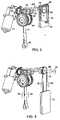
- FIG. 1is a perspective view of the present invention, showing the general arrangement of the elements but with an outer housing partially removed for ease of illustration;
- FIG. 2 ais a close-up view of the main elements of the present invention.
- FIG. 2 bis the same view as 2 a , but with some of the supporting elements removed for illustrating the elements in the drive train;
- FIG. 3shows the drive train of the present invention including a emergency lowering mechanism in a storage position
- FIG. 4is the same view as FIG. 3 , showing the emergency lowering mechanism in a deployed position;
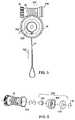
- FIG. 5is a view showing forces on a portion of the present invention when supporting a load
- FIG. 6is an exploded view showing the clutch and brake features of the present invention.
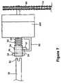
- FIG. 7is a side view of a coupler connected to the emergency lowering mechanism.
- FIG. 8is a perspective view of the drive train elements of a further embodiment of the present invention.
- FIG. 1shows the main elements of the present invention.
- a housing 10 for a personal lift device 11The housing 10 is attached to a base plate 12 .
- the housing 10covers the motor and drive train (described below) of the present invention and protects the same from dirt, dust, contaminants and the like.
- the housing 10is shown partially removed, but it will be understood that in the preferred form the housing 10 fully surrounds and encloses the base plate 12 , as well as the inner workings of the personal lift device 11 .
- a lifting and lowering strap 14 with a looped end 16Shown extending from the housing 10 is a lifting and lowering strap 14 with a looped end 16 .
- the lifting and lowering strap 14may be attached to a patient sling or other lift device 17 , and by means of operation described below, the strap 14 is raised and lowered for the purpose of lifting the patient for facilitating movement of the patient carried in the lift device 17 .
- upper attachment elements 18 , 19that are used to attach the unit to a stand or overhead track 20 by means of a carriage (not shown) or the like.
- the present inventionmay also be used with a moveable stand or tripod, such as will be known in the art.
- FIG. 2 ashows the main elements of the present invention suspended from the plate 12 .
- the main elementsinclude an electric motor 21 , which is mounted under the plate 12 to a drive train support box 24 by screw fasteners or the like.
- the motormay be a 12 VDC Valeo right angle gear drive motor, or any other drive motor that can supply the desired torque and speed.
- the motor 21includes an output or drive shaft 22 , which extends towards the drive train support box 24 .
- the drive train support box 24is also attached to the support plate 12 and includes various elements of the drive train.
- a pair of parallel worm gears of which one is shown at 26are driven by the drive shaft 22 through appropriate gears as explained below.
- the worm gearsare rotatably supported by support fittings 30 , 32 , at one end as shown. Most preferably each of the worm gears are supported on a single worm shaft having at least one ball bearing.
- a spool support plate 34with spool axle 35 in the support box 24 .
- FIG. 2 bshows the same elements as 2 a , but with the support plate 12 and support box 24 removed, to reveal the second worm gear 28 .
- the drive shaft 22includes a drive gear 38 which simultaneously drives both worm gears 26 , 28 , through mating gears 40 , 42 , at the motor end of the worm gears 26 , 28 .
- Both of the worm gearsin turn drive the spool 44 by interacting with teeth of opposed helical side spool gears shown at 46 and 47 .
- the worm gear/spool gear ratiois about 4:50, but other ratios may also be used and are comprehended by the present invention.
- the motorwhen energized, will turn the drive shaft, which in turn will drive the worm gears 26 , 28 . Then, the worm gears turn and cause the spool 44 to turn.
- the strap 14 suspended from the spool 44is either taken up or lowered depending upon the direction the motor 21 is turning.
- twin worm gears 26 , 28 of the present inventionan additional benefit of the twin worm gears 26 , 28 of the present invention is that the forces on the two worm gears are only about one half of the forces otherwise generated on a single worm gear, which means that lower strength materials can be used in the construction of the worm gears. In some cases the twin worm gear design will permit hardened plastics to be used, which reduce the weight and expense of the present invention. Otherwise machined metal parts can also be used.
- the present inventioncomprehends that the output gear of the motor interacts with the drive gears of the worm gears at a ratio of 2:1.
- FIG. 2 balso shows the elements of the emergency lower device according to the present invention.
- a take off gear 60attached to a manual lower shaft 62 , which extends through a bearing holder assembly 64 and ends in chain gear 66 .
- the take off gear 60engages the gears 40 , 42 , and is either driven or drives the same, depending upon the circumstances, as described in more detail below.
- the bearing holder assembly 64rotatably houses the manual lower shaft 62 while holding the shaft in place.
- the assembly 64preferably includes pivoting chain guides 68 , 70 which are sized and shaped to guide, for example, a chain 74 over chain gear 66 .
- a chain 74( FIG. 4 ) is carried in the cover 72 and is most preferably in the form of a loop or endless section.
- the chainincludes link elements sized and shaped to engage the teeth of chain gear 66 .
- the cover 72is releasably mounted on the bearing holder assembly 64 . Releasing the cover 72 simply requires a sharp pull in a downward direction. Most preferably the cover 72 is sized, shaped and attached in a way that enables it to be easily dislodged with any convenient reach extender, such as a broom handle, or the like. As the cover 72 is lowered, the chain 74 , otherwise stored in the cover 72 , plays out and extends down.
- the chainis of a length suitable for being easily reached by a person standing on the floor, even if the device 11 is mounted on the ceiling. Good results have been achieved with the chain 74 falling four feet below its raised position.
- the cover 72most preferably includes a chain post so that the cover is permanently attached around the chain 74 .
- the chain 74In the raised position the chain 74 is preferably supported above the chain gear 66 , and so is not driven while the motor is raising or lowering patients.
- the balance of the chain 74is neatly stored inside of the cover 72 .
- the present inventioncomprehends all forms of manually actuable elongate elements for use in the emergency lift and lower situation, such as ropes, extended crank handles, and the like, but a chain 74 is the most preferred form.
- the chaincan be held out of engagement with the gear when not in use, and is flexible enough to be easily stored in the cover 72 when not in use. Then, when needed the chain 74 can be dropped onto the gear 66 as the cover 72 is lowered.
- the flexible chain 74will deploy out of the cover 72 and extend below the device 11 until it is in easy reach.
- the positive engagement of the links of the chain 74 on the chain gear 66 sprocketsis helpful in providing enough traction to the chain 74 on the gear 66 to permit enough force to be generated to raise or lower the weight on the strap 14 without slipping.
- the present inventioncomprehends forming the cover so that when the cover is pulled down, the chain is then caused to sit on and engage with the chain gear 66 .
- an attendantis provided with a means to easily lower the patient down, even if the motor has malfunctioned.
- the chain gearwill be caused to rotate, in turn rotating the worm gears and the spool, and thus raising or lowering the strap 14 as needed.
- a gear box 300which may be used to alter the gear ratio of the shaft 62 , to permit the mechanical advantage to be optimized.
- the present inventioncomprehends adjusting the mechanical advantage, first, by sizing the gears 60 , 40 , and 42 and 38 , and then, if desired, through use of a gear box 300 as shown.
- FIG. 3the cover 72 is shown mounted on the chain gear.
- the chain guides 68 , 70are in a raised position, supporting the chain 74 free of chain gear 66 . It will be understood that various configurations of elements can be used, and that the preferred form of chain guides that act to guide the chain in a lower position but pivot to a raised chain supporting position provides good results.
- FIG. 4the cover is shown pulled off and exposing the chain gear 66 , with the chain 74 engaging the chain gear 66 .
- pulling on the chain 74 in the direction of arrow 80causes the chain gear to rotate in direction of arrow 82 , causing the strap 14 to move in direction of arrow 84 .
- pulling the chain 74 in direction of arrow 86causes a rotation in direction of arrow 88 , moving the strap 14 in the direction of arrow 90 .
- an easily accessible and manually operable emergency lift or lower facilityis provided to the device of the present invention.
- the chain gear 66is in essence a take off means, for providing access to the drive train of the lift and lower device from outside. While a chain is one form of releasable element for remotely driving the take off means, other forms, such as releasable crank handles, are also comprehended. Such a crank handle can be stored unattached, and then lifted and attached if and when needed.
- FIG. 7Another configuration that has provided adequate results is shown in FIG. 7 .
- a coupler 50may be inserted between the shaft 62 and the gear box 300 .
- the couplerfunctions to disengage or separate the chain gear 66 from the shaft 62 during normal operation of the lift device, i.e. when the patient load is being lifted or lowered by rotation of the motor 21 .
- the coupler 50can be activated to connect shaft 62 to gear chain 66 .
- shaft 62is provided with an open-ended slot 52 at a termination point.
- a corresponding shaft 53 having a slot 56projects from gear box 300 .
- Shaft 53ends at coupler 50 , which is a generally hollow tubular element intersected by pins 54 and 55 .
- Coupler 50is attachable to shaft 53 through the insertion of pin 54 into slot 56 , and is slidable over shaft 53 .
- the hollow interior of coupler 50is also sized and shaped to fit over shaft 62
- pin 55is sized and shaped to fit inside slot 52 .
- Pin 54has an external portion 57 that engages a lock 58 .
- lock 58may be simply a hook or stop against which external portion 57 can rest.
- An elastically deformable element or spring 59fits over shaft 53 between the coupler 50 and the side of gear box 300 , and provides a bias urging coupler 50 towards shaft 62 .
- coupler 50is shown in a retracted or locked position, with external portion 57 resting against lock 58 . It can be appreciated that in this position chain gear 66 will be unaffected by the spinning of lower shaft 62 .
- FIG. 8shows an alternate embodiment of the present invention in which the device is operated manually rather than by electrical power.
- Motor 21is accordingly replaced by a chain gear 92 and corresponding chain 94 .
- chain gear 92may be configured to rotate the same output shaft, which turns drive gear 38 , as that otherwise rotated by motor 21 . Since motor or electrical failure is not a concern in this embodiment, a separate emergency lower facility is not needed.
- This embodimentmay also perform adequately with a single worm gear, as shown in FIG. 8 , in cases where the expected load is suitably reduced.
- FIG. 5certain elements of the present invention are shown in isolation for ease of understanding.
- the spool 44is shown, with the lifting strap 14 extending below the spool 44 .
- One of the worm gears 26 , 28is shown with the mating gear 40 at one end and a braking assembly 100 at the other end.
- the strapis wound around the spool and by means of a strap guide is fed out below the centre of the spool 44 .
- the weight carried by the spool 44indicated by arrow 102 , creates a force 104 that drives the worm gear onto the braking assembly 100 .
- the greater the weightthe greater the force on the braking assembly 100 .
- FIG. 6the elements of the braking assembly 100 are shown in exploded detail.
- a one-way clutch bearing 106is provided upon which is mounted a cone shaped brake element 108 .
- a conical braking or slip surface 110is formed in the end of the worm gear 26 , which is sized and shaped to match with the conical surface 112 of the cone shaped brake element 108 .
- a ball-bearing 114is also mounted onto the same axle as the cone shaped brake element 108 .
- the cone shaped brake elementcan be rotated in direction of arrow 116 together with the worm gear.
- the ball-bearingis not rotatable, meaning that for there to be any rotation the rotation must occur between the cone shaped brake surface 112 and the slip surface 110 of the worm gear 26 .
- the cone shaped brake surface 112will have a braking force that is a function of the seating force, namely how strongly the worm gear is pushed onto the brake surface 112 .
- the seating forceis a function of the weight suspended by the strap, so the greater the suspended weight the greater the seating force and the greater the braking force.
- a braking forcecan be generated which is larger for larger weights.
- the braking forceis self-compensating to be strong enough to support all patients, and yet for lighter patients will be less than for heavier patients.
- the present inventionoffers a more efficient use of motor power. Even though the braking force increases with increased weight, since the weight being supported is also increased the difference remains within a reasonable range over different weights. Thus the present invention comprehends that the motor be sized and shaped as needed and of a relatively low power to cause the brake force to be overcome and for lowering to be achieved. As this low power will be somewhat constant over a range of weights being lowered, less energy is required for each lowered weight. This contrasts with the prior art, in which the inefficient gear train means that the more weight being supported, the stronger the motor must be (both in terms of maximum torque and total work). Personal lift devices are rated according to how many lift and lower cycles can be obtained from a single battery charge. By increasing the efficiency, as comprehended by this invention, either more cycles can be obtained for the same power leading to a higher rating, or smaller batteries can be used to deliver the same rating at a reduced cost.
- the amount of braking forceis a function of a number of variables that are interrelated in a complex way. Some of these variables include the size of the in-contact overlapping brake surfaces, the angles at which the surfaces intersect, the smoothness of the surfaces, and the force exerted between the surfaces causing them to come together. By predetermined design these variables can be selected to provide a brake assembly having a preferred brake force profile to facilitate the objectives of the present invention.
- the present inventionwill include a form of hand held control to start and control the motor.
- the controlcould be either hard wired, by means of a connecting cable to a control circuit in the device, pneumatic, or operable by remote control. In some cases the former is preferred to prevent the control unit from being separated and lost.
- the present inventioncomprehends the control unit having, among other things, a raise button or control. Associated with the control system is a limit switch on the motor assembly to prevent the device from being over raised, which could cause damage to the motor and other components. Thus, once the strap has been retracted a maximum amount, the motor will be simply disengaged from further motion in the raise direction by means of the limit switch.
- governoris simply a latch that is pivotally mounted at one end onto the spool. The mounting is such that when the spool rotates, the other end of the latch is urged outwardly. The faster the spool rotates the greater the outward urging under centrifugal acceleration. The ability of the latch to move will be restricted until a force is generated that represents uncontrolled descent of the strap. Then the latch will extend outwardly, as shown at 202 , and lock the spool against any further rotation.
Landscapes
- Health & Medical Sciences (AREA)
- Nursing (AREA)
- Life Sciences & Earth Sciences (AREA)
- Animal Behavior & Ethology (AREA)
- General Health & Medical Sciences (AREA)
- Public Health (AREA)
- Veterinary Medicine (AREA)
- Engineering & Computer Science (AREA)
- Mechanical Engineering (AREA)
- Invalid Beds And Related Equipment (AREA)
- Braking Arrangements (AREA)
Abstract
Description
- a motor having an output shaft;
- a gearing system operatively connected to said output shaft for increasing torque;
- a strap for suspending a weight;
- a spool for suspending said strap and for extending and retracting said strap;
- a drive connection between said gearing system and said spool to permit said motor to drive said spool;
- a brake, associated with said spool to prevent unwanted extension of said strap from said spool, when a force is applied to said strap; wherein the gearing system is efficient enough to permit the spool to back drive, in the absence of a brake.
- an operative connection between said brake and said spool;
- a clutch to permit said spool to turn without overcoming the brake when said weight is being raised by said strap;
- a frictional slip interface which slips when said weight is being lowered;
- wherein a braking force generated at said frictional slip interface is correlated to said weight, to generate a larger braking force under greater weights.
- a cover releasably attached to said device,
- an elongate manually actuable element stored in said cover, and
- a drive train take off point associated with said cover, wherein, upon said cover being detached from said device, said element engages said take off point to permit movement of said element to raise or lower a weight suspended by said device.
- a cover for protecting a drive train of said personal lift device;
- a take off means extending from said cover and accessible from outside of said cover, said take off means operably connected to a drive train of said personal lift device; and
- a manually actuable element, releasably connected to said take off means, to remotely drive said take off means when said element is connected and to permit said element to be stored out of the way when said element is disconnected.
Claims (21)
Priority Applications (1)
| Application Number | Priority Date | Filing Date | Title |
|---|---|---|---|
| US11/803,361US7634825B2 (en) | 2002-01-28 | 2007-05-14 | Personal lift device |
Applications Claiming Priority (3)
| Application Number | Priority Date | Filing Date | Title |
|---|---|---|---|
| CA2,369,668 | 2002-01-28 | ||
| CA2369668ACA2369668C (en) | 2002-01-28 | 2002-01-28 | Personal lift device |
| PCT/CA2003/000094WO2003064312A2 (en) | 2002-01-28 | 2003-01-27 | Personal lift device |
Related Child Applications (1)
| Application Number | Title | Priority Date | Filing Date |
|---|---|---|---|
| US11/803,361DivisionUS7634825B2 (en) | 2002-01-28 | 2007-05-14 | Personal lift device |
Publications (2)
| Publication Number | Publication Date |
|---|---|
| US20050115914A1 US20050115914A1 (en) | 2005-06-02 |
| US7240621B2true US7240621B2 (en) | 2007-07-10 |
Family
ID=27626538
Family Applications (3)
| Application Number | Title | Priority Date | Filing Date |
|---|---|---|---|
| US10/502,815Expired - LifetimeUS7240621B2 (en) | 2002-01-28 | 2003-01-27 | Personal lift device |
| US11/803,361Expired - LifetimeUS7634825B2 (en) | 2002-01-28 | 2007-05-14 | Personal lift device |
| US12/616,569Expired - Fee RelatedUS8128068B2 (en) | 2002-01-28 | 2009-11-11 | Personal lift device |
Family Applications After (2)
| Application Number | Title | Priority Date | Filing Date |
|---|---|---|---|
| US11/803,361Expired - LifetimeUS7634825B2 (en) | 2002-01-28 | 2007-05-14 | Personal lift device |
| US12/616,569Expired - Fee RelatedUS8128068B2 (en) | 2002-01-28 | 2009-11-11 | Personal lift device |
Country Status (4)
| Country | Link |
|---|---|
| US (3) | US7240621B2 (en) |
| EP (1) | EP1472176A2 (en) |
| CA (2) | CA2369668C (en) |
| WO (1) | WO2003064312A2 (en) |
Cited By (37)
| Publication number | Priority date | Publication date | Assignee | Title |
|---|---|---|---|---|
| US20080287268A1 (en)* | 2007-05-14 | 2008-11-20 | Joseph Hidler | Body Weight Support System and Method of Using the Same |
| US20090077737A1 (en)* | 2004-02-06 | 2009-03-26 | Invacare Ec-Hong A/S | Rail-mounted patient or person lift |
| US7634825B2 (en)* | 2002-01-28 | 2009-12-22 | Prism Medical Ltd. | Personal lift device |
| US20100064432A1 (en)* | 2008-09-11 | 2010-03-18 | Duquette Noel | Infection control lifting strap |
| US20100270252A1 (en)* | 2006-03-30 | 2010-10-28 | Prism Medical Ltd. | Ceiling Lift and Ceiling Lift Components |
| US20110016628A1 (en)* | 2009-07-21 | 2011-01-27 | Masterson Jr Russell P | Portable apparatus for moving subjects |
| US20120179289A1 (en)* | 2011-01-07 | 2012-07-12 | Siemens Medical Solutions Usa, Inc. | Integrated Patient Pull Up System |
| WO2012112771A2 (en) | 2011-02-17 | 2012-08-23 | Woodlark Circle, Inc. | Inflatable sling and method for positioning a patient |
| US20130038263A1 (en)* | 2010-02-12 | 2013-02-14 | Arjohuntleigh Magog Inc. | Lift apparatus and system |
| US8458827B2 (en) | 2010-05-03 | 2013-06-11 | Dewey Darrow | Patient positioning system and rail for use therein |
| US20140013503A1 (en)* | 2012-07-12 | 2014-01-16 | Steven A. Dixon | Monitoring Systems Devices and Methods for Patient Lifts |
| US20140131301A1 (en)* | 2012-11-12 | 2014-05-15 | Hill-Rom Services, Inc. | Support system for a lift motor unit |
| US20140201905A1 (en)* | 2013-01-20 | 2014-07-24 | Bioness Inc. | Methods and apparatus for body weight support system |
| US8978905B2 (en) | 2010-07-02 | 2015-03-17 | Liko Research & Development Ab | Lift systems with continuous in-rail charging |
| US9161873B2 (en) | 2012-06-20 | 2015-10-20 | Jary Edward Tindall | System and method for extricating a victim |
| US9855177B2 (en) | 2013-01-20 | 2018-01-02 | Bioness Inc. | Methods and apparatus for body weight support system |
| US9914003B2 (en) | 2013-03-05 | 2018-03-13 | Alterg, Inc. | Monocolumn unweighting systems |
| US10010468B2 (en) | 2008-09-11 | 2018-07-03 | 1073849 Ontario Limited | Infection control strap and patient lifting system |
| US10265565B2 (en) | 2013-03-14 | 2019-04-23 | Alterg, Inc. | Support frame and related unweighting system |
| US10314758B2 (en) | 2015-07-31 | 2019-06-11 | Allen Medical Systems, Inc. | Person support apparatus with tracking features |
| US10342461B2 (en) | 2007-10-15 | 2019-07-09 | Alterg, Inc. | Method of gait evaluation and training with differential pressure system |
| US10376434B2 (en) | 2015-07-31 | 2019-08-13 | Liko Research & Developmetn AB | Person lift devices and scale assemblies for person lift devices including accessory tracking features |
| US10463563B2 (en) | 2013-01-20 | 2019-11-05 | Bioness Inc. | Methods and apparatus for body weight support system |
| US10478361B2 (en) | 2015-07-01 | 2019-11-19 | Liko Research & Development Ab | Person lifting devices and methods for operating person lifting devices |
| US10478360B2 (en) | 2015-07-01 | 2019-11-19 | Liko Research & Development Ab | Person lifting devices with accessory detection features and methods for operating the same |
| US10493309B2 (en) | 2013-03-14 | 2019-12-03 | Alterg, Inc. | Cantilevered unweighting systems |
| US10500123B2 (en) | 2015-11-11 | 2019-12-10 | Bioness Inc. | Apparatus and methods for support track and power rail switching in a body weight support system |
| USD874732S1 (en) | 2018-05-01 | 2020-02-04 | TSG Associates, LLP | Hoistable harness |
| US10646392B2 (en) | 2013-03-14 | 2020-05-12 | Liko Research & Development Ab | Split drum for lift strap in ceiling lift |
| US10668316B2 (en) | 2017-02-14 | 2020-06-02 | Bioness Inc. | Methods and apparatus for body weight support system |
| US11191688B2 (en)* | 2018-01-11 | 2021-12-07 | Liko Research & Development Ab | Person lifting apparatuses including lifting straps and methods of operation |
| USD941947S1 (en) | 2018-05-16 | 2022-01-25 | TSG Associates, LLP | Flotation device |
| US11452653B2 (en) | 2019-01-22 | 2022-09-27 | Joseph Hidler | Gait training via perturbations provided by body-weight support system |
| US11464696B2 (en) | 2016-09-09 | 2022-10-11 | Bioness Inc. | Methods and apparatus for body weight support system |
| US11542128B2 (en)* | 2018-12-11 | 2023-01-03 | Liko Research & Development Ab | Subject lift transfer assemblies and methods for operating the same |
| US11806564B2 (en) | 2013-03-14 | 2023-11-07 | Alterg, Inc. | Method of gait evaluation and training with differential pressure system |
| US11957954B2 (en) | 2017-10-18 | 2024-04-16 | Alterg, Inc. | Gait data collection and analytics system and methods for operating unweighting training systems |
Families Citing this family (40)
| Publication number | Priority date | Publication date | Assignee | Title |
|---|---|---|---|---|
| CA2436731C (en) | 2003-08-06 | 2012-04-03 | Peter Shaw | Linear lift drive device |
| GB2418902B (en)* | 2004-10-07 | 2008-06-25 | Days Medical Aids Ltd | Invalid hoist |
| USD553825S1 (en) | 2006-03-30 | 2007-10-23 | Waverly Glen Systems Ltd. | Ceiling lift |
| CA2638276A1 (en)* | 2008-07-24 | 2010-01-24 | Prism Medical Ltd. | Component frame assembly for patient lift devices |
| CA2649950A1 (en)* | 2009-01-15 | 2010-07-15 | Prism Medical Ltd. | Patient lift device |
| US8978821B2 (en) | 2009-07-10 | 2015-03-17 | Transol Corporation | Anchor trolley and fall arrest system and method implementing the same |
| US20110101293A1 (en)* | 2009-10-30 | 2011-05-05 | Production Resource Group L.L.C. | Workhorse Winch |
| US8887865B2 (en)* | 2010-03-05 | 2014-11-18 | Tractel Limited | Device of assistance for a user of a ladder |
| US20110225728A1 (en)* | 2010-03-19 | 2011-09-22 | Lyn Thornhill | Tym-lyn portable lift system |
| US9222498B2 (en) | 2011-09-08 | 2015-12-29 | Arjohuntleigh Magog, Inc. | Lifting bar and lifting bar connector |
| PT10756U (en)* | 2011-11-11 | 2012-10-08 | Vertequip Equipamentos E Trabalhos Verticias Lda | EQUIPMENT FOR THE DISPLACEMENT OF PEOPLE IN HEIGHT ON NON-HORIZONTAL SURFACES WITH VERTICAL AND HORIZONTAL TRANSLATION |
| WO2014093340A1 (en)* | 2012-12-10 | 2014-06-19 | Donald Hackett | Brake and capture system for zip lining |
| US9089465B2 (en)* | 2013-02-05 | 2015-07-28 | University Of Delaware | Open area harness system for providing patient mobility |
| US9867754B2 (en) | 2013-08-10 | 2018-01-16 | Donald Burke | Magnetic conveyance system |
| EP2901997B1 (en)* | 2014-02-03 | 2019-10-02 | Liko Research & Development AB | Person lift system |
| KR101479697B1 (en)* | 2014-04-11 | 2015-01-07 | (주)오티에스 | Auto-Lift Equipment for CCTV Camera Maintenance |
| US10729606B2 (en)* | 2015-05-15 | 2020-08-04 | Liko Research & Development Ab | Adaptive mobility lift |
| WO2017059526A1 (en)* | 2015-10-05 | 2017-04-13 | Amico Mobility Solutions Corp. | Patient lift system |
| DE102015117767B4 (en)* | 2015-10-19 | 2023-11-16 | Airbus Operations Gmbh | Aircraft's own mobility system for passengers |
| GB2549474B (en)* | 2016-04-18 | 2018-04-11 | Joerns Healthcare Ltd | Patient ceiling-hoist carriage |
| USD805152S1 (en) | 2016-07-28 | 2017-12-12 | Shannon David Scott | Swing |
| CN107139939A (en)* | 2016-11-18 | 2017-09-08 | 河北师范大学 | A kind of urban road is met an urgent need transportation system |
| US11096852B2 (en)* | 2017-06-01 | 2021-08-24 | Liko Research & Development Ab | Systems for monitoring person lifting devices using load tension pins |
| ES2717650B2 (en)* | 2017-12-22 | 2019-12-16 | Univ Extremadura | Safety support system for sports training |
| US10876679B2 (en)* | 2018-01-29 | 2020-12-29 | George Monir | Personal radiation garment suspension system |
| US10730535B2 (en) | 2018-02-01 | 2020-08-04 | Donald Andrew HACKETT | Emergency arrest device for zip line |
| SE543644C2 (en)* | 2019-09-26 | 2021-05-11 | Arjo Ip Holding Ab | Locking arrangement for patient lift |
| CN111707387B (en)* | 2020-06-24 | 2022-06-10 | 广东韶钢松山股份有限公司 | Refining furnace temperature measuring gun lifting device and method |
| SE544777C2 (en) | 2020-08-17 | 2022-11-15 | Arjo Ip Holding Ab | Drive system for patient lift comprising a transmission with a worm drive |
| US12064384B2 (en) | 2020-11-06 | 2024-08-20 | Liko Research & Development Ab | Overhead lifts having a release assembly for disengaging an electromagnetic brake and methods for disengaging an electromagnetic brake of an overhead lift |
| WO2022159909A1 (en)* | 2021-01-25 | 2022-07-28 | Allied Motion Technologies Inc. | Electronic winch spool lock and gear changing transmission |
| WO2022159907A1 (en)* | 2021-01-25 | 2022-07-28 | Allied Motion Technologies Inc. | Winch having a bi-directional, backstopping clutch and/or torque coupler, and torque coupler for a winch |
| US11807283B2 (en) | 2021-03-05 | 2023-11-07 | Donald Andrew HACKETT | Emergency arrest device for zip-lining |
| CN113545942B (en)* | 2021-07-26 | 2022-10-11 | 安徽科技学院 | Multifunctional nursing bed for helping aged |
| CN113562590B (en)* | 2021-07-26 | 2022-03-29 | 江苏天华索具有限公司 | Safe hoisting belt for hoisting gantry |
| US12144771B2 (en)* | 2021-08-09 | 2024-11-19 | Nutech Ventures | Cable-based body-weight support |
| CN114224646A (en)* | 2021-12-16 | 2022-03-25 | 吉林大学 | Carrying device for bedridden patient |
| CN115353021A (en)* | 2022-08-15 | 2022-11-18 | 广西电网有限责任公司来宾供电局 | Portable automatic lifting tool |
| CN115057352B (en)* | 2022-08-18 | 2022-11-15 | 河南华工实业集团有限公司 | Embedded gear ratio speed governing crane wheel |
| CN118545606B (en)* | 2024-07-30 | 2024-10-11 | 四川佰业鑫建设工程有限公司 | Steel construction I-beam hoisting assembly for construction |
Citations (26)
| Publication number | Priority date | Publication date | Assignee | Title |
|---|---|---|---|---|
| US1536766A (en)* | 1921-03-01 | 1925-05-05 | Hermann H Cammann | Invalid lifter |
| US2272778A (en)* | 1939-09-05 | 1942-02-10 | Paul A Reuter | Apparatus for lifting invalids |
| US3123224A (en)* | 1964-03-03 | Apparatus for lifting and transporting invalids | ||
| US3351959A (en)* | 1966-04-22 | 1967-11-14 | Bobby G Turpin | Invalid lift |
| US3569809A (en) | 1968-01-22 | 1971-03-09 | Mobility Systems Inc | Dc electric motor control systems |
| US3629880A (en) | 1968-09-10 | 1971-12-28 | Johannes Nicolaas Van Rhyn | Apparatus for assisting invalids |
| US4117561A (en) | 1976-04-16 | 1978-10-03 | Zamotin Rodvinon I | Patient lift device |
| US4138077A (en)* | 1977-10-18 | 1979-02-06 | Haruto Okumura | Helicopter-carried rescue apparatus |
| US4202064A (en) | 1977-04-26 | 1980-05-13 | Joergensen Gunnar I | Unit for vertical and horizontal personal transport |
| US4425674A (en) | 1980-12-01 | 1984-01-17 | B-W Health Products, Inc. | Transmission for adjustable hospital bed |
| DE3432043A1 (en) | 1984-08-31 | 1986-03-13 | Werner 6349 Sinn Nickel | Lifting device, in particular for medical transport and/or excercise appliances |
| DE3442138A1 (en) | 1984-11-17 | 1986-05-22 | Rhein-Getriebe Gmbh, 4005 Meerbusch | Self-locking worm gearing |
| DE3516714A1 (en) | 1985-05-09 | 1986-11-13 | Keiper Recaro GmbH & Co, 5630 Remscheid | Joint fitting with two joint components which can be pivoted in relation to one another, in particular for vehicle seats |
| US4633538A (en) | 1984-02-14 | 1987-01-06 | James Industries Limited | Invalid hoist |
| GB2201449A (en) | 1987-02-23 | 1988-09-01 | Autoliv Dev | A locking device |
| US4944056A (en) | 1988-09-28 | 1990-07-31 | The Research Foundation Of State University Of Ny | Method and apparatus for transporting a disabled person |
| US5038425A (en) | 1990-09-13 | 1991-08-13 | Anodyne Corporation | Patient chair suspension assembly |
| US5072840A (en)* | 1989-12-28 | 1991-12-17 | Yoshio Asakawa | Medical bed apparatus |
| US5165123A (en) | 1991-08-27 | 1992-11-24 | Colpron Ishmael C | Wheelchair overhead lifting apparatus |
| US5327592A (en) | 1993-06-07 | 1994-07-12 | Stump Floyd V | Stationary patient lift |
| US5553335A (en) | 1992-01-27 | 1996-09-10 | Lahtinen; Veli-Tapani | Lifting device for sick or motion-handicapped person |
| US5588932A (en) | 1992-06-29 | 1996-12-31 | Linvent Ab | Device for the setting of the mutual positions of pivotable elements |
| US5694654A (en)* | 1996-05-01 | 1997-12-09 | Roy; Duane L. | Patient lifting and transfer system |
| US5809591A (en) | 1996-03-19 | 1998-09-22 | Lift Aid, Inc. | Patient lift mechanism |
| CA2217421A1 (en) | 1997-10-03 | 1999-04-03 | Stephane Robert | A person lowering and raising winch assembly |
| WO2000026133A1 (en) | 1998-10-30 | 2000-05-11 | Atecs Mannesmann Ag | Winding mechanism with a housing |
Family Cites Families (11)
| Publication number | Priority date | Publication date | Assignee | Title |
|---|---|---|---|---|
| US4243147A (en)* | 1979-03-12 | 1981-01-06 | Twitchell Brent L | Three-dimensional lift |
| US4372452A (en)* | 1980-12-24 | 1983-02-08 | Independent Transfer Equipment Co. | Transfer hoist for disabled persons |
| US5074423A (en)* | 1989-05-26 | 1991-12-24 | Ingersoll-Rand Company | Low-profile lifting apparatus |
| US5138953A (en) | 1991-01-09 | 1992-08-18 | Horcher Gmbh & Co. Kg | Transportation device with a load carrier suspended movably from a rail for a suspended load |
| AU666078B2 (en)* | 1993-07-02 | 1996-01-25 | Elephant Chain Block Company Limited | Manual chain block |
| US5544863A (en)* | 1993-07-02 | 1996-08-13 | Elephant Chain Block Company Limited | Manual chain block |
| DE9421601U1 (en)* | 1994-10-15 | 1996-05-23 | MICO-Gesellschaft für industrielle Automation mbH, 73037 Göppingen | Spur gear as a rotary drive for winches or the like. |
| US5871069A (en)* | 1996-09-23 | 1999-02-16 | Carmitchel; Richard A. | Combination motorized and manual drive for lifts |
| CA2284855C (en)* | 1999-10-05 | 2002-01-01 | Gestion Techno-Medic Inc. | Automatic displacement and homing system for a rail mounted patient lift |
| CA2369668C (en)* | 2002-01-28 | 2010-05-04 | Waverley Glen Systems Ltd. | Personal lift device |
| WO2004073576A2 (en)* | 2003-02-18 | 2004-09-02 | British Columbia Institute Of Technology | Portable raising and lowering device and equipment therefor |
- 2002
- 2002-01-28CACA2369668Apatent/CA2369668C/ennot_activeExpired - Fee Related
- 2003
- 2003-01-27CACA2417506Apatent/CA2417506C/ennot_activeExpired - Lifetime
- 2003-01-27WOPCT/CA2003/000094patent/WO2003064312A2/ennot_activeApplication Discontinuation
- 2003-01-27EPEP03701376Apatent/EP1472176A2/ennot_activeWithdrawn
- 2003-01-27USUS10/502,815patent/US7240621B2/ennot_activeExpired - Lifetime
- 2007
- 2007-05-14USUS11/803,361patent/US7634825B2/ennot_activeExpired - Lifetime
- 2009
- 2009-11-11USUS12/616,569patent/US8128068B2/ennot_activeExpired - Fee Related
Patent Citations (26)
| Publication number | Priority date | Publication date | Assignee | Title |
|---|---|---|---|---|
| US3123224A (en)* | 1964-03-03 | Apparatus for lifting and transporting invalids | ||
| US1536766A (en)* | 1921-03-01 | 1925-05-05 | Hermann H Cammann | Invalid lifter |
| US2272778A (en)* | 1939-09-05 | 1942-02-10 | Paul A Reuter | Apparatus for lifting invalids |
| US3351959A (en)* | 1966-04-22 | 1967-11-14 | Bobby G Turpin | Invalid lift |
| US3569809A (en) | 1968-01-22 | 1971-03-09 | Mobility Systems Inc | Dc electric motor control systems |
| US3629880A (en) | 1968-09-10 | 1971-12-28 | Johannes Nicolaas Van Rhyn | Apparatus for assisting invalids |
| US4117561A (en) | 1976-04-16 | 1978-10-03 | Zamotin Rodvinon I | Patient lift device |
| US4202064A (en) | 1977-04-26 | 1980-05-13 | Joergensen Gunnar I | Unit for vertical and horizontal personal transport |
| US4138077A (en)* | 1977-10-18 | 1979-02-06 | Haruto Okumura | Helicopter-carried rescue apparatus |
| US4425674A (en) | 1980-12-01 | 1984-01-17 | B-W Health Products, Inc. | Transmission for adjustable hospital bed |
| US4633538A (en) | 1984-02-14 | 1987-01-06 | James Industries Limited | Invalid hoist |
| DE3432043A1 (en) | 1984-08-31 | 1986-03-13 | Werner 6349 Sinn Nickel | Lifting device, in particular for medical transport and/or excercise appliances |
| DE3442138A1 (en) | 1984-11-17 | 1986-05-22 | Rhein-Getriebe Gmbh, 4005 Meerbusch | Self-locking worm gearing |
| DE3516714A1 (en) | 1985-05-09 | 1986-11-13 | Keiper Recaro GmbH & Co, 5630 Remscheid | Joint fitting with two joint components which can be pivoted in relation to one another, in particular for vehicle seats |
| GB2201449A (en) | 1987-02-23 | 1988-09-01 | Autoliv Dev | A locking device |
| US4944056A (en) | 1988-09-28 | 1990-07-31 | The Research Foundation Of State University Of Ny | Method and apparatus for transporting a disabled person |
| US5072840A (en)* | 1989-12-28 | 1991-12-17 | Yoshio Asakawa | Medical bed apparatus |
| US5038425A (en) | 1990-09-13 | 1991-08-13 | Anodyne Corporation | Patient chair suspension assembly |
| US5165123A (en) | 1991-08-27 | 1992-11-24 | Colpron Ishmael C | Wheelchair overhead lifting apparatus |
| US5553335A (en) | 1992-01-27 | 1996-09-10 | Lahtinen; Veli-Tapani | Lifting device for sick or motion-handicapped person |
| US5588932A (en) | 1992-06-29 | 1996-12-31 | Linvent Ab | Device for the setting of the mutual positions of pivotable elements |
| US5327592A (en) | 1993-06-07 | 1994-07-12 | Stump Floyd V | Stationary patient lift |
| US5809591A (en) | 1996-03-19 | 1998-09-22 | Lift Aid, Inc. | Patient lift mechanism |
| US5694654A (en)* | 1996-05-01 | 1997-12-09 | Roy; Duane L. | Patient lifting and transfer system |
| CA2217421A1 (en) | 1997-10-03 | 1999-04-03 | Stephane Robert | A person lowering and raising winch assembly |
| WO2000026133A1 (en) | 1998-10-30 | 2000-05-11 | Atecs Mannesmann Ag | Winding mechanism with a housing |
Cited By (60)
| Publication number | Priority date | Publication date | Assignee | Title |
|---|---|---|---|---|
| US7634825B2 (en)* | 2002-01-28 | 2009-12-22 | Prism Medical Ltd. | Personal lift device |
| US20090077737A1 (en)* | 2004-02-06 | 2009-03-26 | Invacare Ec-Hong A/S | Rail-mounted patient or person lift |
| US20100270252A1 (en)* | 2006-03-30 | 2010-10-28 | Prism Medical Ltd. | Ceiling Lift and Ceiling Lift Components |
| US7883450B2 (en)* | 2007-05-14 | 2011-02-08 | Joseph Hidler | Body weight support system and method of using the same |
| US20080287268A1 (en)* | 2007-05-14 | 2008-11-20 | Joseph Hidler | Body Weight Support System and Method of Using the Same |
| US10342461B2 (en) | 2007-10-15 | 2019-07-09 | Alterg, Inc. | Method of gait evaluation and training with differential pressure system |
| US20100064432A1 (en)* | 2008-09-11 | 2010-03-18 | Duquette Noel | Infection control lifting strap |
| US10010468B2 (en) | 2008-09-11 | 2018-07-03 | 1073849 Ontario Limited | Infection control strap and patient lifting system |
| US20110016628A1 (en)* | 2009-07-21 | 2011-01-27 | Masterson Jr Russell P | Portable apparatus for moving subjects |
| AU2011214911B2 (en)* | 2010-02-12 | 2015-05-07 | Arjohuntleigh Magog Inc. | Lift apparatus and system |
| US20130038263A1 (en)* | 2010-02-12 | 2013-02-14 | Arjohuntleigh Magog Inc. | Lift apparatus and system |
| US8910325B2 (en)* | 2010-02-12 | 2014-12-16 | Arjohuntleigh Magog Inc. | Lift apparatus and system |
| US8458827B2 (en) | 2010-05-03 | 2013-06-11 | Dewey Darrow | Patient positioning system and rail for use therein |
| US9796168B2 (en) | 2010-07-02 | 2017-10-24 | Liko Research & Development Ab | Lift systems with continuous in-rail charging |
| US8978905B2 (en) | 2010-07-02 | 2015-03-17 | Liko Research & Development Ab | Lift systems with continuous in-rail charging |
| US20120179289A1 (en)* | 2011-01-07 | 2012-07-12 | Siemens Medical Solutions Usa, Inc. | Integrated Patient Pull Up System |
| US9131907B2 (en)* | 2011-01-07 | 2015-09-15 | Siemens Medical Solutions Usa, Inc. | Integrated patient pull up system |
| US8566977B2 (en) | 2011-02-17 | 2013-10-29 | Woodlark Circle, Inc. | Inflatable sling and method for positioning a patient |
| WO2012112771A2 (en) | 2011-02-17 | 2012-08-23 | Woodlark Circle, Inc. | Inflatable sling and method for positioning a patient |
| US9161873B2 (en) | 2012-06-20 | 2015-10-20 | Jary Edward Tindall | System and method for extricating a victim |
| US20140013503A1 (en)* | 2012-07-12 | 2014-01-16 | Steven A. Dixon | Monitoring Systems Devices and Methods for Patient Lifts |
| US10420690B2 (en)* | 2012-07-12 | 2019-09-24 | Liko Research & Development Ab | Monitoring systems devices and methods for patient lifts |
| US9629769B2 (en)* | 2012-11-12 | 2017-04-25 | Hill-Rom Services, Inc. | Support system for a lift motor unit |
| US20140131301A1 (en)* | 2012-11-12 | 2014-05-15 | Hill-Rom Services, Inc. | Support system for a lift motor unit |
| US11246780B2 (en) | 2013-01-20 | 2022-02-15 | Bioness Inc. | Methods and apparatus for body weight support system |
| US12161597B2 (en) | 2013-01-20 | 2024-12-10 | Bioness Inc. | Methods and apparatus for body weight support system |
| US9855177B2 (en) | 2013-01-20 | 2018-01-02 | Bioness Inc. | Methods and apparatus for body weight support system |
| US10219960B2 (en) | 2013-01-20 | 2019-03-05 | Bioness Inc. | Methods and apparatus for body weight support system |
| US10537486B2 (en) | 2013-01-20 | 2020-01-21 | Bioness Inc. | Methods and apparatus for body weight support system |
| US11253416B2 (en) | 2013-01-20 | 2022-02-22 | Bioness Inc. | Methods and apparatus for body weight support system |
| US9839569B2 (en) | 2013-01-20 | 2017-12-12 | MannGroup,LLC | Methods and apparatus for body weight support system |
| US20140201905A1 (en)* | 2013-01-20 | 2014-07-24 | Bioness Inc. | Methods and apparatus for body weight support system |
| US9682000B2 (en)* | 2013-01-20 | 2017-06-20 | Bioness, Inc. | Methods and apparatus for body weight support system |
| US10463563B2 (en) | 2013-01-20 | 2019-11-05 | Bioness Inc. | Methods and apparatus for body weight support system |
| US11324651B2 (en) | 2013-01-20 | 2022-05-10 | Bioness Inc. | Methods and apparatus for body weight support system |
| US11400004B2 (en) | 2013-01-20 | 2022-08-02 | Bioness Inc. | Methods and apparatus for body weight support system |
| US11406549B2 (en) | 2013-01-20 | 2022-08-09 | Bioness Inc. | Methods and apparatus for body weight support system |
| US12042461B2 (en) | 2013-01-20 | 2024-07-23 | Bioness Inc. | Methods and apparatus for body weight support system |
| US9914003B2 (en) | 2013-03-05 | 2018-03-13 | Alterg, Inc. | Monocolumn unweighting systems |
| US11806564B2 (en) | 2013-03-14 | 2023-11-07 | Alterg, Inc. | Method of gait evaluation and training with differential pressure system |
| US10646392B2 (en) | 2013-03-14 | 2020-05-12 | Liko Research & Development Ab | Split drum for lift strap in ceiling lift |
| US11679049B2 (en) | 2013-03-14 | 2023-06-20 | Liko Research & Development Ab | Split drum for lift strap in ceiling strap |
| US10493309B2 (en) | 2013-03-14 | 2019-12-03 | Alterg, Inc. | Cantilevered unweighting systems |
| US10265565B2 (en) | 2013-03-14 | 2019-04-23 | Alterg, Inc. | Support frame and related unweighting system |
| US10596052B2 (en) | 2015-07-01 | 2020-03-24 | Liko Research & Development Ab | Person lifting devices with accessory detection features and methods for operating the same |
| US10478360B2 (en) | 2015-07-01 | 2019-11-19 | Liko Research & Development Ab | Person lifting devices with accessory detection features and methods for operating the same |
| US10478361B2 (en) | 2015-07-01 | 2019-11-19 | Liko Research & Development Ab | Person lifting devices and methods for operating person lifting devices |
| US10314758B2 (en) | 2015-07-31 | 2019-06-11 | Allen Medical Systems, Inc. | Person support apparatus with tracking features |
| US10918549B2 (en) | 2015-07-31 | 2021-02-16 | Liko Research & Development Ab | Person lift devices and scale assemblies for person lift devices including accessory tracking features |
| US10376434B2 (en) | 2015-07-31 | 2019-08-13 | Liko Research & Developmetn AB | Person lift devices and scale assemblies for person lift devices including accessory tracking features |
| US10500123B2 (en) | 2015-11-11 | 2019-12-10 | Bioness Inc. | Apparatus and methods for support track and power rail switching in a body weight support system |
| US11464696B2 (en) | 2016-09-09 | 2022-10-11 | Bioness Inc. | Methods and apparatus for body weight support system |
| US10668316B2 (en) | 2017-02-14 | 2020-06-02 | Bioness Inc. | Methods and apparatus for body weight support system |
| US11779795B2 (en) | 2017-02-14 | 2023-10-10 | Bioness Inc. | Methods and apparatus for body weight support system |
| US11957954B2 (en) | 2017-10-18 | 2024-04-16 | Alterg, Inc. | Gait data collection and analytics system and methods for operating unweighting training systems |
| US11191688B2 (en)* | 2018-01-11 | 2021-12-07 | Liko Research & Development Ab | Person lifting apparatuses including lifting straps and methods of operation |
| USD874732S1 (en) | 2018-05-01 | 2020-02-04 | TSG Associates, LLP | Hoistable harness |
| USD941947S1 (en) | 2018-05-16 | 2022-01-25 | TSG Associates, LLP | Flotation device |
| US11542128B2 (en)* | 2018-12-11 | 2023-01-03 | Liko Research & Development Ab | Subject lift transfer assemblies and methods for operating the same |
| US11452653B2 (en) | 2019-01-22 | 2022-09-27 | Joseph Hidler | Gait training via perturbations provided by body-weight support system |
Also Published As
| Publication number | Publication date |
|---|---|
| US20050115914A1 (en) | 2005-06-02 |
| US20070215569A1 (en) | 2007-09-20 |
| CA2369668A1 (en) | 2003-07-28 |
| US20100051889A1 (en) | 2010-03-04 |
| WO2003064312A3 (en) | 2003-11-20 |
| EP1472176A2 (en) | 2004-11-03 |
| US7634825B2 (en) | 2009-12-22 |
| CA2369668C (en) | 2010-05-04 |
| CA2417506C (en) | 2010-12-07 |
| CA2417506A1 (en) | 2003-07-28 |
| WO2003064312A2 (en) | 2003-08-07 |
| US8128068B2 (en) | 2012-03-06 |
Similar Documents
| Publication | Publication Date | Title |
|---|---|---|
| US7240621B2 (en) | Personal lift device | |
| CA2514217C (en) | Powered rope climbing apparatus | |
| EP1027024B1 (en) | A person lowering and raising winch assembly | |
| EP1617797B1 (en) | Portable raising and lowering device and equipment therefor | |
| CN110745725B (en) | Electric lifter | |
| HUP9903252A2 (en) | Emergency release device | |
| JPS61135676A (en) | Controlled falling apparatus | |
| US20120018689A1 (en) | Patient Lift Device | |
| US7055653B2 (en) | Escape device | |
| CN211301819U (en) | Life-saving device | |
| AU2003203071A1 (en) | Personal lift device | |
| CN2211833Y (en) | Fire lifesaving device | |
| CN2689971Y (en) | Self rescue device for high rise building | |
| WO1993006810A1 (en) | Patient lifting device | |
| CN2136049Y (en) | Safety fall arrest device for working at heights | |
| AU2004205392B2 (en) | Powered rope climbing apparatus | |
| CN210117180U (en) | Adjusting frame for cliff descending | |
| BR102015019221A2 (en) | LIFT FOR TRANSPORT OF PERSONS WITH REDUCED PHYSICAL CAPACITY | |
| JP3020716U (en) | Portable droppers | |
| JP2004016718A (en) | Transfer assisting device for care | |
| AU2675892A (en) | Patient lifting device | |
| JPH0780091A (en) | Descending escaping device for emergency refuge |
Legal Events
| Date | Code | Title | Description |
|---|---|---|---|
| AS | Assignment | Owner name:CORVEN HEALTHCARE INC., CANADA Free format text:ASSIGNMENT OF ASSIGNORS INTEREST;ASSIGNOR:WAVERLEY GLEN SYSTEMS LTD.;REEL/FRAME:016072/0404 Effective date:20020612 Owner name:CORVEN HEALTHCARE INC., CANADA Free format text:ASSIGNMENT OF ASSIGNORS INTEREST;ASSIGNORS:CHEPURNY, MARK;MOLNAR, GORDON J.;WILSON, MICHAEL F.;REEL/FRAME:016314/0560;SIGNING DATES FROM 20030401 TO 20030407 Owner name:WAVERLEY GLEN SYSTEMS LTD., CANADA Free format text:ASSIGNMENT OF ASSIGNORS INTEREST;ASSIGNORS:WILSON, MICHAEL F.;CHEPURNY, MARK;MOLNAR, GORDON J.;REEL/FRAME:016072/0407;SIGNING DATES FROM 20020521 TO 20020604 | |
| AS | Assignment | Owner name:PRISM MEDICAL LTD., ONTARIO Free format text:MERGER;ASSIGNOR:WAVERLY GLEN SYSTEMS LTD.;REEL/FRAME:019262/0801 Effective date:20061201 Owner name:WAVERLY GLEN SYSTEMS LTD., ONTARIO Free format text:MERGER;ASSIGNORS:CORVEN HEALTH CARE INC.;PRISM MEDICAL DEVELOPMENTS INC.;REEL/FRAME:019262/0779 Effective date:20051201 | |
| STCF | Information on status: patent grant | Free format text:PATENTED CASE | |
| FPAY | Fee payment | Year of fee payment:4 | |
| FEPP | Fee payment procedure | Free format text:PAT HOLDER CLAIMS SMALL ENTITY STATUS, ENTITY STATUS SET TO SMALL (ORIGINAL EVENT CODE: LTOS); ENTITY STATUS OF PATENT OWNER: SMALL ENTITY | |
| FPAY | Fee payment | Year of fee payment:8 | |
| AS | Assignment | Owner name:HANDICARE CANADA LTD., CANADA Free format text:CHANGE OF NAME;ASSIGNOR:PRISM MEDICAL LTD.;REEL/FRAME:046353/0658 Effective date:20171130 | |
| MAFP | Maintenance fee payment | Free format text:PAYMENT OF MAINTENANCE FEE, 12TH YR, SMALL ENTITY (ORIGINAL EVENT CODE: M2553); ENTITY STATUS OF PATENT OWNER: SMALL ENTITY Year of fee payment:12 | |
| AS | Assignment | Owner name:HANDICARE CANADA LTD., CANADA Free format text:CHANGE OF ADDRESS;ASSIGNOR:HANDICARE CANADA LTD.;REEL/FRAME:054525/0929 Effective date:20171130 | |
| AS | Assignment | Owner name:NATIONAL BANK OF CANADA, CANADA Free format text:SECURITY INTEREST;ASSIGNOR:HANDICARE CANADA LTD.;REEL/FRAME:057004/0436 Effective date:20210706 |