US7239911B2 - Method for localizing at least one focal lesion in a biological tissue section - Google Patents
Method for localizing at least one focal lesion in a biological tissue sectionDownload PDFInfo
- Publication number
- US7239911B2 US7239911B2US10/614,944US61494403AUS7239911B2US 7239911 B2US7239911 B2US 7239911B2US 61494403 AUS61494403 AUS 61494403AUS 7239911 B2US7239911 B2US 7239911B2
- Authority
- US
- United States
- Prior art keywords
- tissue section
- electrical
- lesion
- maximum
- localizing
- Prior art date
- Legal status (The legal status is an assumption and is not a legal conclusion. Google has not performed a legal analysis and makes no representation as to the accuracy of the status listed.)
- Expired - Lifetime, expires
Links
Images


Classifications
- A—HUMAN NECESSITIES
- A61—MEDICAL OR VETERINARY SCIENCE; HYGIENE
- A61B—DIAGNOSIS; SURGERY; IDENTIFICATION
- A61B5/00—Measuring for diagnostic purposes; Identification of persons
- A61B5/05—Detecting, measuring or recording for diagnosis by means of electric currents or magnetic fields; Measuring using microwaves or radio waves
- A61B5/053—Measuring electrical impedance or conductance of a portion of the body
Definitions
- a method of the above typeis disclosed by PCT Application WO99/48422.
- electrical currentsare impressed and/or electrical voltages are applied to an examination subject at one or more locations therein.
- Voltages that arise due to the impressed currentsare measured using M electrodes (M ⁇ 1) that are brought into electrical contact with the tissue section under examination at one or more locations.
- currents that are established due to the applied voltagesare measured either exclusively or additionally as well.
- the voltages and/or currentsare determined by the electrical properties of the subject (described, for example, by the complex conductivity in the mathematical sense). Measured data at m different locations thus are obtained.
- the electrical conductivityis composed of a d.c. component and frequency-dependent polarization current components.
- the electrical conductivityis accordingly mathematically described as a complex quantity.
- time-dependent current valuescan be measured at present at the surface of the female breast by means of 8 ⁇ 8 or 16 ⁇ 16 regularly arranged electrodes using an apparatus of the TransScan Company that is distributed under the name TS2000.
- the measurement areaamounts to approximately 7.9 ⁇ 7.9 cm 2 .
- the measured current valuesarise due to an alternating voltage between the measuring electrodes and a reference electrode at the contra-lateral hand.
- the measured data, magnitude and phase of the currentare individually converted into conductance values and capacitance values are presented in conformity with the two-dimensional electrode arrangement.
- An object of the present inventionis to provide a simple and fast method for localizing a focal lesion in a tissue section.
- the localization methodis thus limited to only a single coordinate direction.
- any localization methodcan be employed for the localizing in depth direction, however, the application of a localizing method by means of orthogonal lead fields is especially advantageous.
- the result of the localizingis the center of gravity of the focal lesion.
- FIG. 1is an overview presentation showing the basic components of device for localizing and identifying a focal lesion in a tissue section in accordance with the invention.
- FIG. 2shows the basic method steps for localizing and classifying a focal lesion in accordance with the invention.
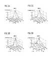
- FIGS. 3A through 3Dshow clinical conductance values of a malignant, focal breast lesion.
- FIG. 4is a presentation of the localization function as function of the depth.
- FIG. 1shows a measurement and evaluation arrangement with which signal activities of a limited spatial region 2 can be localized in a biological tissue section 4 and identified. It is assumed that the spatial region 2 has an electrical conductivity different from the surrounding tissue section 4 , and that the remaining tissue section 4 exhibits an electrical conductivity that is essentially spatially constant. These assumptions are adequately met when the biological tissue section 4 is a female breast and the limited spatial region 2 is a tumor.
- the measurement arrangementincludes an applicator 6 having a number of spatially distributed electrodes 8 that are brought into contact with the surface of the tissue section 4 .
- an applicator 6having a number of spatially distributed electrodes 8 that are brought into contact with the surface of the tissue section 4 .
- the electrodes 8are connected to an electrical energy source (current source or voltage source) 12 via electrical leads 10 and to a measured value editor 16 via electrical leads 14 .
- a cooperating electrode 18is arranged at that side of the tissue section 4 lying opposite the applicator 6 .
- the cooperating electrode 18is likewise connected to the current source 12 in the case of potential measurements relative to the voltage source 12 , and in the case of current measurements to the measured value editor 16 . There is also the possibility of fashioning a part of the applicator 6 as a cooperating electrode.
- alternating currentsin the case of potential measurements
- alternating voltagesin the case of current measurements
- K electrodesin order to generate a spatial current distribution thereat, whereby 1 ⁇ K ⁇ M applies.
- Limited spatial regions 2 that have a different electrical conductivity than the surrounding tissue 4are electrically polarized by the externally supplied currents or applied voltages such that the polarized spatial regions 2 can be approximately considered as focal bioelectrical signal sources.
- the respective signal intensityis dependent on the size and on the frequency-dependent, complex conductivity of the spatial region 2 under observation.
- the localization and identification of spatially limited regions 2is reduced to the locating and the determination of the strength of such bioelectrical signal sources by measuring the potentials generated by the supplied currents on the surface of the tissue section 4 at M electrode locations, or the currents generated in the tissue section 4 by the applied voltages are measured at the M electrode locations and are supplied for an evaluation. Since the frequency dependency of the electrical conductivity in the limited spatial regions 2 represents an important quantity for characterizing (classifying) or identifying the corresponding tissue, the current source can generate 12 currents or the voltage source can generate 12 voltages with N different frequencies that, for example, lie in the range from 100 Hz through 500 kHz and are supplied to the tissue section 4 .
- the measured value editor 16includes, for example, measuring amplifiers, filters and analog-to-digital converters.
- the measured value editor 16is connected to one or more data inputs of an electronic computer 20 .
- a model 22 of the tissue section 4is made available to the computer 20 , the aforementioned bioelectrical signal sources being localized and identified with the assistance of this model 22 , as described below.
- the resultfor example in the form of a graphic presentation of the anatomy of the tissue section wherein the location of the signal sources, and thus of the spatial regions 2 is marked, ensues via a monitor 24 . Additionally, a quantity characterizing the signal activity is presented at the monitor 24 that is dependent on the current or voltage frequencies.
- a higher-ranking input and control 26is provided with which the number and the location of the feed electrodes 8 or of the voltage electrodes 8 , the value of the current or voltage frequency, and the model 22 are prescribed.
- a localization methodis explained as an example below on the basis of FIG. 2 .
- the input quantitiesi.e. the measured data and the model data, are discussed, followed by the method steps.
- Input quantities for the localizing methodare:
- the data Dcan be current and/or voltage values that were measured at a fixed time with respect to a reference signal, or can be linear combinations of current and/or voltage values that were acquired at a number of times with respect to a reference signal.
- the datacan be converted into conductance values and/or capacitance values.
- the following considerationsare independent of the measuring time or times. The measurement times therefore have not been included as arguments in the formulaic expressions.
- admittance datacan be purely real (only electrical conductance) or purely imaginary (only susceptances) or can be complex (both conductance and susceptance).
- the data matrix Dcan also be derived from a linear combination of at least two datasets. For example, the difference between a dataset with lesion signals and a spatially adjacent dataset without lesion signal can be observed. The amount of the exciting electrical field is clearly reduced in, if not eliminated from the difference data.
- edge artifactscan be eliminated by cutting edge data off. They can simulate a non-existent frequency dependency.
- volume conductorThe simplest example of a volume conductor is conductive, infinite space.
- “conductive”recognizes the fact that the conductivity of the medium observed is complex. This means that ohmic as well as dielectric properties are described.
- Another example of a volume conductoris the conductive, infinite half-space. Both models are patient-independent.
- the electrical lead fields for current measurements or potential measurementsare the electrical field components or potentials generated by a point source having the intensity of ‘one’ at the location r k that can be measured with the given measuring arrangement that is defined by the normal vector n m with respect to the m th measurement electrode at the location r m .
- the signal processing of the methodis composed of
- the M indices of the column vectors u qcorrespond to the consecutively numbered indices of the quadratically arranged measurement electrodes. Accordingly, these column vectors can be converted into ⁇ square root over (M) ⁇ square root over (M) ⁇ -dimensional matrices, and the real/imaginary parts can be presented like two-dimensional measured value distributions.
- These column vectorsare frequency-independent, ortho-normalized base vectors in the M-dimensional data space and are referred to herein as eigenmaps since they can in turn be presented as measured value distribution over the electrode arrangement.
- a u q vectoris 256-dimensional. Accordingly, it can be entered as a generally complex 16 ⁇ 16 measured value distribution.
- the singular value analysis 108yields the number Q dom of significant singular values and, thus, the number of independent signal sources.
- the appertaining column vectors u qare considered as base vectors of a frequency-independent Q dom -dimensional signal space in the M-dimensional data space.
- the remaining M-Q dom column vectorsare then the base vectors of the orthogonal signal space. This space is referred to as noise space in earlier literature.
- Seeking focal conductivity inhomogeneitiescorresponds to the search for locations/center of gravity locations of induced signal sources.
- This searchby means of a computer requires the division into discrete values of the assumed model volume conductor that is intended to mathematically simulate the body region 4 to be examined.
- the search strategyis to generate model data with normalized and orthogonalized lead fields at every grid location and to compare these to the frequency-independent signal space acquired from the measured data.
- the locations at which a distance dimension between signal space and model data space assumes a local minimumare interpreted as locations of actual signal sources, and thus of the lesions 2 .
- the model dataare derived from a post-processing of the lead fields.
- the individual leadfieldsare respectively referenced to their norm, so that the normalized leadfields L k (n) arise as follows:
- Orthogonalized leadfieldsare then acquired by a singular value resolution 118 of the M ⁇ K lead field matrix L (n) .
- the normalizationis indicated by the index (n).
- a suitable criterionis the function
- the actual localization function Fis the minimum values of the distances F k . It is defined by
- the local minimums of the localization functionare ordered monotonously ascending according to their numerical values.
- the locations that are to be assigned to the first Q dom ⁇ 1 local minimumsare considered locations of signal generators. The reduction by one takes into consideration that a significant singular value is caused by the tissue surrounding the signal source. However, local minimums that lie below the noise threshold are excluded as signal locations in the consideration.
- the localization method described in general aboveis employed here in order to determine only one dimension of the location of the lesion after the two other coordinate values have been identified in the manner described below.
- All peak locationsare selected in the two-dimensional distributions for a number of exposure frequencies of, for example, 256 admittance data given a measurement arrangement having 16 ⁇ 16 electrodes. It may occur that peaks attenuate or intensify at certain frequencies or in frequency ranges. The determination of peaks can occur in two ways:
- a first resultis the specification of the spatial positions of the lesion centers of gravity. This result can be graphically visualized on the monitor: for example, 2D plot of the localization function over the depth and marking the minimums as lesion locations and/or marking the locations in 3D presentations of the breast region or in appertaining 2D projection planes and/or marking in fusion images that are acquired by combined ultrasound and/or X-ray mammography exposures.
- a second resultis the tissue classification on the basis of the tissue-typical frequency behavior of the multi-pole moments of the detected lesions.
- the frequency behavior of the multi-pole momentscan be graphically displayed on the monitor in various ways. These, for example, can be:
- FIGS. 3A through 3Dshow clinical conductance value data of a malignant, focal breast lesion (recorded with the TS2000 system of the TransScan company) at a depth of 13 mm.
- the search resultcan be presented as indicated in FIG. 4 .
- the z-directionhere corresponds to the depth direction in which the search is carried out.
- a lesion center of gravitywas found at a depth of 10 mm.
- the multi-pole moments at the location of the lesionare then determined in the next step. Only those multi-pole moments whose contributions to the measured signal lie above the noise level are thereby identified.
Landscapes
- Health & Medical Sciences (AREA)
- Life Sciences & Earth Sciences (AREA)
- Biomedical Technology (AREA)
- Heart & Thoracic Surgery (AREA)
- Radiology & Medical Imaging (AREA)
- Biophysics (AREA)
- Pathology (AREA)
- Engineering & Computer Science (AREA)
- Nuclear Medicine, Radiotherapy & Molecular Imaging (AREA)
- Physics & Mathematics (AREA)
- Medical Informatics (AREA)
- Molecular Biology (AREA)
- Surgery (AREA)
- Animal Behavior & Ethology (AREA)
- General Health & Medical Sciences (AREA)
- Public Health (AREA)
- Veterinary Medicine (AREA)
- Measurement And Recording Of Electrical Phenomena And Electrical Characteristics Of The Living Body (AREA)
Abstract
Description
- a) an M×N data matrix D with measured values (reference character102) that is dependent on the M electrode locations
r m,(m=1, . . . , M) and on the N current or voltage frequencies vn,(n=1, . . . , N). - b) A set of K lead fields Lk(
r i,r m,n m), (k=1, . . . , K), for example multi-pole lead fields, that are identified inFIG. 2 withreference character 104 and that are in turn dependent on - a volume conductor model of the
examination region 4, - a modeling of the conductivity inhomogeneities as bioelectrical signal sources at the location
r i, - the type of measurement (measurement of potential and/or current), and
- on the
measurement electrodes 8 in terms of their positionr m, their surface orientation (which is described by the normal vectorn m) and their geometrical expanse.
Lk(
wherein
- 1. the singular value resolution of the data matrix D (
reference character 106 inFIG. 2 ), - 2. the analysis of the singular value resolution (
reference character 108 inFIG. 2 ) and - 3. the actual localizing (
reference character 110 inFIG. 2 ).
D=USVH. (2)
The following apply:
- U—a unitary M×M matrix that is only dependent on the indices of the electrode locations,
- S—the M×N singular value matrix with min (M, N) real singular values in the diagonal and elements that are otherwise disappearing,
- V—a unitary N×N matrix that is only dependent on the frequency indices, and
- H—indicates the Hermitian conjugation.
s1≧s2≧ . . . ≧smin(M,N). (3)

clearly shows that the qthsingular value are [sic] exclusively linked with the qthcolumn vectors of U and V. The single and double underlining for u and v are intended to indicate that it is a matter of M-dimensional or N-dimensional vectors.
L(n)=(L1(n), . . . ,LK(n))=ULSLVLT (6)
The initial equation for the derivation of (7) is
When the solution of the coefficient ciis inserted into the evaluation criterion
then the expression in (7) for Fk(
- Computationally: Determination of the maximums and their 2D coordinates in the measurement plane—referred to as (xp, yp) by declaration.
- Interactively: Clicking on the peak maximum/maximums in graphic presentations of the measured data on a monitor and—following therefrom—the indication of the appertaining 2D coordinates;
- by means of mixing (dot, cross, or the like) into the graphic presentations of the measured data, the computational determination of the maximums can be proposed as a click-on possibility.
- Limiting the search to a distance in depth direction (z-direction) under the peak positions identified above; the 3D coordinates of the points on the distance are (xp, yp, z) with z=0, . . . , zmax, whereby z=0 is the z-coordinate of the measurement plane.
- Determining the path length, i.e. zmax, and dividing the search path.
- Applying a localization method that is based on the analysis of the multi-frequency measured data, as described above. The results of the search method are the 3D centers of gravity of focal lesions.
- As warranted, the determination of the malignant/benign nature of the localize focal lesions follows. The results of this method are the tissue-typical frequency dependencies of the induced multi-pole moments that are to be assigned to the lesions.
- (1) 2D plot of the multi-pole moments (real/imaginary part and/or amount/phase) over the frequency or
- (2) Marking (for example, color coding) the lesion locations In the visualizations recited under (a) dependent on multi-pole result (for example, benign=green, malignant=red).
Claims (1)
Applications Claiming Priority (2)
| Application Number | Priority Date | Filing Date | Title |
|---|---|---|---|
| DE10230813.6 | 2002-07-08 | ||
| DE10230813ADE10230813A1 (en) | 2002-07-08 | 2002-07-08 | Method for localizing at least one focal lesion in a biological tissue section |
Publications (2)
| Publication Number | Publication Date |
|---|---|
| US20040073103A1 US20040073103A1 (en) | 2004-04-15 |
| US7239911B2true US7239911B2 (en) | 2007-07-03 |
Family
ID=29761768
Family Applications (1)
| Application Number | Title | Priority Date | Filing Date |
|---|---|---|---|
| US10/614,944Expired - LifetimeUS7239911B2 (en) | 2002-07-08 | 2003-07-08 | Method for localizing at least one focal lesion in a biological tissue section |
Country Status (2)
| Country | Link |
|---|---|
| US (1) | US7239911B2 (en) |
| DE (1) | DE10230813A1 (en) |
Cited By (28)
| Publication number | Priority date | Publication date | Assignee | Title |
|---|---|---|---|---|
| US7553307B2 (en) | 2004-10-15 | 2009-06-30 | Baxano, Inc. | Devices and methods for tissue modification |
| US7578819B2 (en) | 2005-05-16 | 2009-08-25 | Baxano, Inc. | Spinal access and neural localization |
| US7738969B2 (en) | 2004-10-15 | 2010-06-15 | Baxano, Inc. | Devices and methods for selective surgical removal of tissue |
| US7857813B2 (en) | 2006-08-29 | 2010-12-28 | Baxano, Inc. | Tissue access guidewire system and method |
| US7887538B2 (en) | 2005-10-15 | 2011-02-15 | Baxano, Inc. | Methods and apparatus for tissue modification |
| US7918849B2 (en) | 2004-10-15 | 2011-04-05 | Baxano, Inc. | Devices and methods for tissue access |
| US7938830B2 (en) | 2004-10-15 | 2011-05-10 | Baxano, Inc. | Powered tissue modification devices and methods |
| US7959577B2 (en) | 2007-09-06 | 2011-06-14 | Baxano, Inc. | Method, system, and apparatus for neural localization |
| US8048080B2 (en) | 2004-10-15 | 2011-11-01 | Baxano, Inc. | Flexible tissue rasp |
| US8062300B2 (en) | 2006-05-04 | 2011-11-22 | Baxano, Inc. | Tissue removal with at least partially flexible devices |
| US8062298B2 (en) | 2005-10-15 | 2011-11-22 | Baxano, Inc. | Flexible tissue removal devices and methods |
| US8092456B2 (en) | 2005-10-15 | 2012-01-10 | Baxano, Inc. | Multiple pathways for spinal nerve root decompression from a single access point |
| US8192436B2 (en) | 2007-12-07 | 2012-06-05 | Baxano, Inc. | Tissue modification devices |
| US8221397B2 (en) | 2004-10-15 | 2012-07-17 | Baxano, Inc. | Devices and methods for tissue modification |
| US8257356B2 (en) | 2004-10-15 | 2012-09-04 | Baxano, Inc. | Guidewire exchange systems to treat spinal stenosis |
| US8366712B2 (en) | 2005-10-15 | 2013-02-05 | Baxano, Inc. | Multiple pathways for spinal nerve root decompression from a single access point |
| US8394102B2 (en) | 2009-06-25 | 2013-03-12 | Baxano, Inc. | Surgical tools for treatment of spinal stenosis |
| US8398641B2 (en) | 2008-07-01 | 2013-03-19 | Baxano, Inc. | Tissue modification devices and methods |
| US8409206B2 (en) | 2008-07-01 | 2013-04-02 | Baxano, Inc. | Tissue modification devices and methods |
| US8430881B2 (en) | 2004-10-15 | 2013-04-30 | Baxano, Inc. | Mechanical tissue modification devices and methods |
| US8568416B2 (en) | 2004-10-15 | 2013-10-29 | Baxano Surgical, Inc. | Access and tissue modification systems and methods |
| US8613745B2 (en) | 2004-10-15 | 2013-12-24 | Baxano Surgical, Inc. | Methods, systems and devices for carpal tunnel release |
| US8801626B2 (en) | 2004-10-15 | 2014-08-12 | Baxano Surgical, Inc. | Flexible neural localization devices and methods |
| US8845639B2 (en) | 2008-07-14 | 2014-09-30 | Baxano Surgical, Inc. | Tissue modification devices |
| US9101386B2 (en) | 2004-10-15 | 2015-08-11 | Amendia, Inc. | Devices and methods for treating tissue |
| US9247952B2 (en) | 2004-10-15 | 2016-02-02 | Amendia, Inc. | Devices and methods for tissue access |
| US9314253B2 (en) | 2008-07-01 | 2016-04-19 | Amendia, Inc. | Tissue modification devices and methods |
| US9456829B2 (en) | 2004-10-15 | 2016-10-04 | Amendia, Inc. | Powered tissue modification devices and methods |
Families Citing this family (2)
| Publication number | Priority date | Publication date | Assignee | Title |
|---|---|---|---|---|
| GB2442045A (en)* | 2006-03-22 | 2008-03-26 | Alexander Macrae | Monitoring physiological changes |
| US11617518B2 (en)* | 2007-03-05 | 2023-04-04 | Wisys Technology Foundation, Inc. | Method for detecting both pre-cancerous and cancerous tissues |
Citations (3)
| Publication number | Priority date | Publication date | Assignee | Title |
|---|---|---|---|---|
| WO1999048422A1 (en) | 1998-03-24 | 1999-09-30 | Siemens Aktiengesellschaft | Method for localising and identifying signal activities of at least one delimited area in a section of biological tissue |
| US6308097B1 (en)* | 1994-10-24 | 2001-10-23 | Transscan Medical Ltd. | Tissue characterization based on impedance images and on impedance measurements |
| US6560480B1 (en)* | 1994-10-24 | 2003-05-06 | Transscan Medical Ltd. | Localization of anomalies in tissue and guidance of invasive tools based on impedance imaging |
- 2002
- 2002-07-08DEDE10230813Apatent/DE10230813A1/ennot_activeWithdrawn
- 2003
- 2003-07-08USUS10/614,944patent/US7239911B2/ennot_activeExpired - Lifetime
Patent Citations (3)
| Publication number | Priority date | Publication date | Assignee | Title |
|---|---|---|---|---|
| US6308097B1 (en)* | 1994-10-24 | 2001-10-23 | Transscan Medical Ltd. | Tissue characterization based on impedance images and on impedance measurements |
| US6560480B1 (en)* | 1994-10-24 | 2003-05-06 | Transscan Medical Ltd. | Localization of anomalies in tissue and guidance of invasive tools based on impedance imaging |
| WO1999048422A1 (en) | 1998-03-24 | 1999-09-30 | Siemens Aktiengesellschaft | Method for localising and identifying signal activities of at least one delimited area in a section of biological tissue |
Non-Patent Citations (2)
| Title |
|---|
| "Towards Virtual Electrical Breast Biopsy: Space-Frequency MUSIC for Trans-Admittance Data," Scholz, IEEE Trans. on Medical Imaging, vol. 21, No. 6, Jun. 2002, pp. 588-595. |
| Gencer, Nevzat et al. Differential Characterization of Neural Sources with the Bimodal Truncated SVD Pseudo-Inverse for EEG and MEG Mearsurements, Jul. 7, 1998, IEEE Transations on Biomedical Engineering, vol. 45, No. 7, pp. 827-838.* |
Cited By (52)
| Publication number | Priority date | Publication date | Assignee | Title |
|---|---|---|---|---|
| US7553307B2 (en) | 2004-10-15 | 2009-06-30 | Baxano, Inc. | Devices and methods for tissue modification |
| US9247952B2 (en) | 2004-10-15 | 2016-02-02 | Amendia, Inc. | Devices and methods for tissue access |
| US8579902B2 (en) | 2004-10-15 | 2013-11-12 | Baxano Signal, Inc. | Devices and methods for tissue modification |
| US7738968B2 (en) | 2004-10-15 | 2010-06-15 | Baxano, Inc. | Devices and methods for selective surgical removal of tissue |
| US7738969B2 (en) | 2004-10-15 | 2010-06-15 | Baxano, Inc. | Devices and methods for selective surgical removal of tissue |
| US7740631B2 (en) | 2004-10-15 | 2010-06-22 | Baxano, Inc. | Devices and methods for tissue modification |
| US11382647B2 (en) | 2004-10-15 | 2022-07-12 | Spinal Elements, Inc. | Devices and methods for treating tissue |
| US10052116B2 (en) | 2004-10-15 | 2018-08-21 | Amendia, Inc. | Devices and methods for treating tissue |
| US7918849B2 (en) | 2004-10-15 | 2011-04-05 | Baxano, Inc. | Devices and methods for tissue access |
| US7938830B2 (en) | 2004-10-15 | 2011-05-10 | Baxano, Inc. | Powered tissue modification devices and methods |
| US9463041B2 (en) | 2004-10-15 | 2016-10-11 | Amendia, Inc. | Devices and methods for tissue access |
| US7963915B2 (en) | 2004-10-15 | 2011-06-21 | Baxano, Inc. | Devices and methods for tissue access |
| US8048080B2 (en) | 2004-10-15 | 2011-11-01 | Baxano, Inc. | Flexible tissue rasp |
| US9456829B2 (en) | 2004-10-15 | 2016-10-04 | Amendia, Inc. | Powered tissue modification devices and methods |
| US7555343B2 (en) | 2004-10-15 | 2009-06-30 | Baxano, Inc. | Devices and methods for selective surgical removal of tissue |
| US8613745B2 (en) | 2004-10-15 | 2013-12-24 | Baxano Surgical, Inc. | Methods, systems and devices for carpal tunnel release |
| US8801626B2 (en) | 2004-10-15 | 2014-08-12 | Baxano Surgical, Inc. | Flexible neural localization devices and methods |
| US8192435B2 (en) | 2004-10-15 | 2012-06-05 | Baxano, Inc. | Devices and methods for tissue modification |
| US8221397B2 (en) | 2004-10-15 | 2012-07-17 | Baxano, Inc. | Devices and methods for tissue modification |
| US8257356B2 (en) | 2004-10-15 | 2012-09-04 | Baxano, Inc. | Guidewire exchange systems to treat spinal stenosis |
| US9345491B2 (en) | 2004-10-15 | 2016-05-24 | Amendia, Inc. | Flexible tissue rasp |
| US9101386B2 (en) | 2004-10-15 | 2015-08-11 | Amendia, Inc. | Devices and methods for treating tissue |
| US9320618B2 (en) | 2004-10-15 | 2016-04-26 | Amendia, Inc. | Access and tissue modification systems and methods |
| US8652138B2 (en) | 2004-10-15 | 2014-02-18 | Baxano Surgical, Inc. | Flexible tissue rasp |
| US8647346B2 (en) | 2004-10-15 | 2014-02-11 | Baxano Surgical, Inc. | Devices and methods for tissue modification |
| US8568416B2 (en) | 2004-10-15 | 2013-10-29 | Baxano Surgical, Inc. | Access and tissue modification systems and methods |
| US8430881B2 (en) | 2004-10-15 | 2013-04-30 | Baxano, Inc. | Mechanical tissue modification devices and methods |
| US8617163B2 (en) | 2004-10-15 | 2013-12-31 | Baxano Surgical, Inc. | Methods, systems and devices for carpal tunnel release |
| US8419653B2 (en) | 2005-05-16 | 2013-04-16 | Baxano, Inc. | Spinal access and neural localization |
| US7578819B2 (en) | 2005-05-16 | 2009-08-25 | Baxano, Inc. | Spinal access and neural localization |
| US8062298B2 (en) | 2005-10-15 | 2011-11-22 | Baxano, Inc. | Flexible tissue removal devices and methods |
| US8092456B2 (en) | 2005-10-15 | 2012-01-10 | Baxano, Inc. | Multiple pathways for spinal nerve root decompression from a single access point |
| US7887538B2 (en) | 2005-10-15 | 2011-02-15 | Baxano, Inc. | Methods and apparatus for tissue modification |
| US9492151B2 (en) | 2005-10-15 | 2016-11-15 | Amendia, Inc. | Multiple pathways for spinal nerve root decompression from a single access point |
| US8366712B2 (en) | 2005-10-15 | 2013-02-05 | Baxano, Inc. | Multiple pathways for spinal nerve root decompression from a single access point |
| US9125682B2 (en) | 2005-10-15 | 2015-09-08 | Amendia, Inc. | Multiple pathways for spinal nerve root decompression from a single access point |
| US8062300B2 (en) | 2006-05-04 | 2011-11-22 | Baxano, Inc. | Tissue removal with at least partially flexible devices |
| US9351741B2 (en) | 2006-05-04 | 2016-05-31 | Amendia, Inc. | Flexible tissue removal devices and methods |
| US8585704B2 (en) | 2006-05-04 | 2013-11-19 | Baxano Surgical, Inc. | Flexible tissue removal devices and methods |
| US8551097B2 (en) | 2006-08-29 | 2013-10-08 | Baxano Surgical, Inc. | Tissue access guidewire system and method |
| US7857813B2 (en) | 2006-08-29 | 2010-12-28 | Baxano, Inc. | Tissue access guidewire system and method |
| US8845637B2 (en) | 2006-08-29 | 2014-09-30 | Baxano Surgical, Inc. | Tissue access guidewire system and method |
| US8303516B2 (en) | 2007-09-06 | 2012-11-06 | Baxano, Inc. | Method, system and apparatus for neural localization |
| US7959577B2 (en) | 2007-09-06 | 2011-06-14 | Baxano, Inc. | Method, system, and apparatus for neural localization |
| US8192436B2 (en) | 2007-12-07 | 2012-06-05 | Baxano, Inc. | Tissue modification devices |
| US9463029B2 (en) | 2007-12-07 | 2016-10-11 | Amendia, Inc. | Tissue modification devices |
| US8663228B2 (en) | 2007-12-07 | 2014-03-04 | Baxano Surgical, Inc. | Tissue modification devices |
| US9314253B2 (en) | 2008-07-01 | 2016-04-19 | Amendia, Inc. | Tissue modification devices and methods |
| US8398641B2 (en) | 2008-07-01 | 2013-03-19 | Baxano, Inc. | Tissue modification devices and methods |
| US8409206B2 (en) | 2008-07-01 | 2013-04-02 | Baxano, Inc. | Tissue modification devices and methods |
| US8845639B2 (en) | 2008-07-14 | 2014-09-30 | Baxano Surgical, Inc. | Tissue modification devices |
| US8394102B2 (en) | 2009-06-25 | 2013-03-12 | Baxano, Inc. | Surgical tools for treatment of spinal stenosis |
Also Published As
| Publication number | Publication date |
|---|---|
| DE10230813A1 (en) | 2004-01-22 |
| US20040073103A1 (en) | 2004-04-15 |
Similar Documents
| Publication | Publication Date | Title |
|---|---|---|
| US7239911B2 (en) | Method for localizing at least one focal lesion in a biological tissue section | |
| US7583994B2 (en) | Apparatus for localizing a focal lesion in a biological tissue section | |
| KR102687814B1 (en) | Low-frequency alternating current conductivity estimates below 1 MHz obtained from two MRI images with different repetition times. | |
| Gencer et al. | Electrical conductivity imaging via contactless measurements | |
| Fuchs et al. | Linear and nonlinear current density reconstructions | |
| Chitturi et al. | Spatial resolution in electrical impedance tomography: A topical review | |
| US10278609B2 (en) | Methods for assessing health conditions using single coil magnetic induction tomography imaging | |
| Scholz | Towards virtual electrical breast biopsy: space-frequency MUSIC for trans-admittance data | |
| US8880149B2 (en) | Localization of a device for MR-guided intervention | |
| US7603158B2 (en) | Current density impedance imaging (CDII) | |
| US20080064981A1 (en) | Method and apparatus for determining electrical properties of objects containing inhomogeneities | |
| US6201990B1 (en) | Electrical impedance tomography method | |
| JP5033307B2 (en) | Method and apparatus for creating an electrical property image of a substantially uniform object including heterogeneous portions | |
| Aldhaeebi et al. | Electrically small magnetic probe with PCA for near-field microwave breast tumors detection | |
| EP1520241B1 (en) | Method and system for displaying confidence intervals for source reconstruction | |
| US20190274617A1 (en) | Breast cancer detection using near-field probes with machine learning techniques | |
| JP6678985B2 (en) | Diagnostic device | |
| Cherepenin et al. | An electrical impedance tomography system for gynecological application GIT with a tiny electrode array | |
| Seo et al. | A mathematical model for breast cancer lesion estimation: Electrical impedance technique using TS2000 commercial system | |
| US20240050163A1 (en) | Tracking the position of an interventional device | |
| Ireland et al. | Towards magnetic detection electrical impedance tomography: data acquisition and image reconstruction of current density in phantoms and in vivo | |
| US7209781B2 (en) | Method for localizing at least one focal lesion in a biological tissue section | |
| JP4567318B2 (en) | Method and apparatus for measuring position of region in biological tissue part | |
| Sillaparaya et al. | Planar Electrode Configurations of Electrode Plates for the Localization of Cervical Abnormality based on Electrical Impedance Tomography (EIT)–A Simulation Study | |
| US20040243019A1 (en) | Weighted gradient method and system for diagnosing disease |
Legal Events
| Date | Code | Title | Description |
|---|---|---|---|
| AS | Assignment | Owner name:SIEMENS AKTIENGESELLCHAFT, GERMANY Free format text:ASSIGNMENT OF ASSIGNORS INTEREST;ASSIGNOR:SCHOLZ, BERNHARD;REEL/FRAME:014724/0556 Effective date:20031007 | |
| STCF | Information on status: patent grant | Free format text:PATENTED CASE | |
| FPAY | Fee payment | Year of fee payment:4 | |
| FPAY | Fee payment | Year of fee payment:8 | |
| AS | Assignment | Owner name:SIEMENS HEALTHCARE GMBH, GERMANY Free format text:ASSIGNMENT OF ASSIGNORS INTEREST;ASSIGNOR:SIEMENS AKTIENGESELLSCHAFT;REEL/FRAME:039271/0561 Effective date:20160610 | |
| MAFP | Maintenance fee payment | Free format text:PAYMENT OF MAINTENANCE FEE, 12TH YEAR, LARGE ENTITY (ORIGINAL EVENT CODE: M1553); ENTITY STATUS OF PATENT OWNER: LARGE ENTITY Year of fee payment:12 | |
| AS | Assignment | Owner name:SIEMENS HEALTHINEERS AG, GERMANY Free format text:ASSIGNMENT OF ASSIGNORS INTEREST;ASSIGNOR:SIEMENS HEALTHCARE GMBH;REEL/FRAME:066088/0256 Effective date:20231219 | |
| AS | Assignment | Owner name:SIEMENS HEALTHINEERS AG, GERMANY Free format text:CORRECTIVE ASSIGNMENT TO CORRECT THE ASSIGNEE PREVIOUSLY RECORDED AT REEL: 066088 FRAME: 0256. ASSIGNOR(S) HEREBY CONFIRMS THE ASSIGNMENT;ASSIGNOR:SIEMENS HEALTHCARE GMBH;REEL/FRAME:071178/0246 Effective date:20231219 |