US7239523B1 - Electronic assembly with modular midplane - Google Patents
Electronic assembly with modular midplaneDownload PDFInfo
- Publication number
- US7239523B1 US7239523B1US11/093,285US9328505AUS7239523B1US 7239523 B1US7239523 B1US 7239523B1US 9328505 AUS9328505 AUS 9328505AUS 7239523 B1US7239523 B1US 7239523B1
- Authority
- US
- United States
- Prior art keywords
- midplane
- chassis
- opening
- housing
- assembly
- Prior art date
- Legal status (The legal status is an assumption and is not a legal conclusion. Google has not performed a legal analysis and makes no representation as to the accuracy of the status listed.)
- Expired - Lifetime, expires
Links
Images


Classifications
- H—ELECTRICITY
- H05—ELECTRIC TECHNIQUES NOT OTHERWISE PROVIDED FOR
- H05K—PRINTED CIRCUITS; CASINGS OR CONSTRUCTIONAL DETAILS OF ELECTRIC APPARATUS; MANUFACTURE OF ASSEMBLAGES OF ELECTRICAL COMPONENTS
- H05K7/00—Constructional details common to different types of electric apparatus
- H05K7/14—Mounting supporting structure in casing or on frame or rack
- H05K7/1438—Back panels or connecting means therefor; Terminals; Coding means to avoid wrong insertion
- H05K7/1439—Back panel mother boards
- H05K7/1445—Back panel mother boards with double-sided connections
Definitions
- the present inventionis directed toward an electronic assembly with a removable midplane, and more specifically, toward an electronic assembly comprising a chassis for supporting a plurality of electronic components and a modular removable midplane electrically connectable to electronic components supported by the chassis.
- Assemblies for supporting a plurality of electrical components and connecting them to various power supplies, inputs, outputs and/or to one anotherare well known.
- the electrical componentsare often modular and can be individually connected to and removed from the assembly.
- Such assembliesmay be referred to, for example, as electrical cabinets or racks and generally comprise a structural frame or chassis that supports the electrical components.
- the assemblymay be at least partially surrounded by a housing to protect the electrical components.
- the housingin some instances, may comprise individual panels secured to the chassis. In other cases, a housing may include structural supports integrated therewith and lack a distinct chassis.
- chassiswill generally refer to structural elements of an electronic assembly and “housing” will refer to elements provided primarily for protecting or covering the electronic modules whether these elements are separately provided or integrally formed.
- a midplaneis frequently a printed circuit board (PCB) having a plurality of connectors connectable to the electronic modules supported by the assembly.
- PCBprinted circuit board
- a midplaneis generally provided toward the middle of an assembly and often includes electrical connectors on front and rear surfaces thereof so that modules can be connected to both sides.
- Typical assembliesinclude a chassis that is constructed around a midplane, which essentially makes the midplane an integral part of the chassis. This is especially true in the case of “dual bay” or “multi-bay” assemblies which are arranged to support multiple levels of electronic modules stacked vertically and thus have at least two bays on their front and rear sides. If a midplane requires repair or if an upgrade to the midplane is needed, the chassis must be disassembled to a significant degree to access the midplane. This is often difficult to do at a site where the assembly is installed because it may be difficult or impossible to properly realign the midplane with the chassis when it is reinstalled in the assembly. Moreover, employees or contractors skilled in assembling sheet metal chassis may not be adept at handling printed circuit boards, and a printed circuit board may be damaged when a chassis is assembled around it. Electrostatic discharge, for example, can damage the PCB if care is not taken during chassis assembly.
- FIG. 1is a perspective view of a chassis for an assembly according to an embodiment of the present invention
- FIG. 2is a partially exploded perspective view of an assembly including the chassis of FIG. 1 , a midplane, and a housing;
- FIG. 3is a perspective view of the assembly of FIG. 2 including a plurality of electronic modules mounted in bays of the assembly;
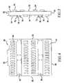
- FIG. 4is a rear elevational view of the midplane of FIG. 2 ;
- FIG. 5is a side elevational view of the midplane of FIG. 2 ;
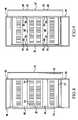
- FIG. 6is a side elevational view, partly in section, of the assembly of FIG. 2 ;
- FIG. 7is a sectional view taken along line VII—VII of FIG. 3 illustrating a first midplane mounting arrangement
- FIG. 8is a sectional front elevational view of an assembly according to an embodiment of the present invention illustrating a first alternate midplane mounting arrangement
- FIG. 9is a sectional front elevational view of an assembly according to an embodiment of the present invention illustrating a third alternate midplane mounting arrangement
- FIG. 10is a side elevational view of an assembly according to a second embodiment of the present invention.
- FIG. 11is a flow chart illustrating a method of assembling an electrical assembly according to an aspect of the present invention.
- FIG. 1illustrates a chassis 10 formed from a plurality of vertical framing members 12 and horizontal framing members 14 interconnected to form an enclosure in the shape of a rectangular parallelepiped having a front 16 , a rear 18 , a first side 19 and a second side 20 .
- Chassis 10also includes guide plates for guiding and supporting a number of electronics modules 21 (illustrated in FIG.
- a first gap 34 extending from first side 19 of chassis 10 to second side 20 of chassis 10is defined by the pair of middle front guide plates 26 , 28 and middle rear guide plates 30 , 32 for receiving a midplane 36 illustrated, for example in FIG. 2 .
- a second gap 35 running from front 16 of chassis 10 toward rear 18 of chassis 10is defined by first side guide plates 26 , 30 and second side guide plates 28 , 32 and may be used to accommodate an added guide plate 43 as illustrated in FIGS. 2 and 3 .
- an end plate 38is provided on first side 19 of chassis 10 at one end of gap 34 and a frame plate 40 is provided on second side 20 of chassis 10 on the end of gap 34 opposite end plate 38 .
- a U-shaped channel support 41is mounted beneath lower guide plates 22 and 24 and helps guide and support midplane 36 as described hereinafter.
- Upper guide plates 37 , 37 ′ having flanges 39 , 39 ′further define slot 34 . While guide plates 37 , 37 ′ are illustrated as solid plates, they may alternately be formed with vents such as those formed in lower guide plates 22 , 24 and middle guide plates 26 , 28 , 30 , 32 .
- FIGS. 2 and 3illustrate a housing 42 attached to chassis 10 .
- Housing 42comprises a top panel 44 , a first side panel 46 on first side 19 of chassis 10 , and a second side panel 48 on the second side 20 of chassis 10 .
- Second side panel 48includes an opening 50 aligned with frame plate 40 of chassis 10 through which midplane 36 can be inserted into and removed from chassis 10 .
- Housing 42provides protection for components 21 and may also contribute to the rigidity of the overall assembly.
- Various openingsare provided in housing 42 for cooling and wiring connections in a well known manner.
- Midplane 36comprises a PCB that includes a front side 52 , illustrated in FIG. 3 , and a rear side 54 illustrated in FIG. 5 .
- Midplane 36further comprises an upper edge 56 , a lower edge 58 , a first side edge 60 and a second side edge 62 .
- a plurality of connectors 64are provided on front side 52 and rear side 54 , the size, type and wiring of which will depend on the types of electronic modules 21 to be used in the assembly.
- midplane 36further includes first and second braces or stiffeners 66 running between first side edge 60 and second side edge 62 which are formed from a material such as steel, for example, and are designed to increase the rigidity of midplane 36 .
- midplane 36can be inserted into chassis 10 through opening 50 in second side panel 48 of the housing and through frame plate 40 of the chassis 10 through gap 34 between front guide plates 26 , 28 and rear guide plates 30 , 32 until first side edge 60 of midplane 36 abuts end plate 38 of chassis 10 .
- Lower edge 58 of midplane 36is supported by support 41 while the middle guide plate flanges 27 , 29 , 31 and 33 and flanges 39 , 39 ′ on upper guide plate 37 help guide the midplane along slot 34 .
- end plate 38includes a plurality of projections 68 which will help to properly align midplane 36 with respect to chassis 10 .
- projections 68may comprise pins secured to end plate 38 or screws or other fasteners inserted through openings formed in end plate 38 .
- a combination of alignment pins and screwsis used. The specific nature of the alignment mechanism is not critical so long as projections are provided that can be received into alignment openings 70 formed at opposite ends of stiffeners 66 .
- the alignment openings 70 and projections 68are arranged and configured so that midplane 36 will assume a predetermined relationship to guide plates 26 , 28 , 30 and 32 , and hence any electrical modules 21 supported by those guide plates, when electrical modules are inserted into the bays 72 defined by the chassis 10 , guide plates 26 , 28 , 30 and 32 , and any auxiliary dividers 74 as illustrated in FIGS. 2 and 6 .
- Additional fasteners 73extend through openings 75 in the flange 23 of lower guide plate 22 , though openings 75 in flanges 27 and 29 of middle front guide plates 26 and 28 , and through flange 39 ′ of upper guide plate 37 ′ into openings (not shown) in midplane 36 to further secure midplane 36 to the chassis.
- Additional fasteners 73are also provided in the flange 25 of lower rear guide plate 24 and in the flanges 31 , 33 of middle rear guide plates 30 , 32 and in flange 39 of upper guide plate 37 to further align and secure midplane 36
- midplane 36To accommodate variations in the thickness of midplane 36 , slot 34 will generally be slightly wider than the nominal thickness of midplane 36 . Therefore, the midplane will be rigidly fastened to only one set of flanges, such as rear flanges 25 , 31 , 33 , 39 . Fasteners 73 extending through front flanges 23 , 27 , 29 and 39 ′ will extend into openings in the midplane to help hold the midplane in proper position, but the midplane will generally be slightly spaced from these front flanges.
- An access panel 76is provided that is sized to cover opening 50 and attach to second side panel 48 and/or frame plate 40 .
- Access panel 76includes an EMI gasket 77 to provide an EMI seal around opening 50 , and openings 78 aligned with alignment openings 70 near second side edge 62 of midplane 36 .
- Suitable fasteners 80such as pins or screws are inserted through openings 78 and into alignment openings 70 of midplane 36 .
- midplane 36When access panel 76 is then secured to housing 42 , midplane 36 will be secured in a proper orientation with respect to the chassis 10 . Because midplane 36 is locked in place in this manner, it not only maintains a necessary orientation with respect to the chassis 10 and supported electronic elements 21 , but it, together with stiffeners 66 , braces and contributes to the rigidity of chassis 10 . As will appreciated from the foregoing, this arrangement simplifies the removal and repair or replacement of midplane 36 as well.
- end plate 38can be omitted and projections 68 may be supported by first side panel 46 of housing 42 .
- frame plate 40can be omitted and the access panel 76 may be connected directly to second side panel 48 of housing 42 .
- FIG. 8An additional variation of this embodiment of the invention is illustrated in FIG. 8 . Elements identical to those in the first variation are identified with like reference numerals.
- a guide channel 80is provided on end plane 38 (or directly mounted on housing first side panel 46 ), and first side edge 60 of midplane 36 is inserted into this guide channel 80 to hold the midplane 36 in proper orientation with respect to chassis 10 .
- Access panel 76is also provided with a guide channel 82 which is placed over second side edge 62 of midplane 36 as access panel 76 is secured to housing 42 .
- Guide channel 80 and access panel guide channel 82hold midplane 36 securely in place within chassis 10 this secure interconnection allows midplane 36 to increase the rigidity of chassis 10 .
- FIG. 9illustrates an alternate variation of the invention in which elements common to the earlier variations are identified with the same reference numerals; elements related to previously identified elements are identified with the same reference numeral and a prime.
- end plate 38(or first side panel 46 of housing 42 ) is provided with openings 84 that receive projections 86 of stiffeners 66 ′. Openings 88 on access panel 76 ′ receive projections 86 near the second side edge 62 of midplane 36 . Projections 86 and openings 84 , 88 are arranged such that midplane 36 is properly positioned within chassis 10 when the projections are received within the openings and access panel 76 is secured to housing 42 .
- FIG. 10illustrates a second embodiment of the present invention in which elements common to the earlier embodiments are identified with like reference numerals.
- chassis 10is open and not covered with panels forming a housing as in the first embodiment.
- a lower bracket 90is provided on lower guide plate 24 while an upper bracket 92 is provided between two of the horizontal framing members 12 forming chassis 10 .
- Lower bracket 90 and upper bracket 92define, with gap 34 , an opening into which a midplane 36 can be inserted into chassis 10 .
- a first member, such as plate 96is removably connected between second side front guide plate 28 and second side rear guide plate 32 and a second member, such as plate 98 is removably connected to lower guide plate 24 to hold midplane 36 in place.
- the end of gap 34 at first side 19 of chassis 10may be blocked by a portion of one of the horizontal framing members 14 that form chassis 10 or by an additional plate 96 . This arrangement allows the benefits of embodiments of the present invention to be enjoyed even in rack arrangements with an open chassis.
- a chassisis formed for supporting a plurality of electronic elements.
- a housingcomprising at least one panel having an opening is attached to the chassis at a step 102 .
- a midplaneis slid through the opening into the chassis, and at a step 106 , a cover is attached over the opening to hold the midplane in a predetermined position with respect to the chassis.
Landscapes
- Engineering & Computer Science (AREA)
- Microelectronics & Electronic Packaging (AREA)
- Mounting Of Printed Circuit Boards And The Like (AREA)
Abstract
Description
Claims (20)
Priority Applications (1)
| Application Number | Priority Date | Filing Date | Title |
|---|---|---|---|
| US11/093,285US7239523B1 (en) | 2005-03-30 | 2005-03-30 | Electronic assembly with modular midplane |
Applications Claiming Priority (1)
| Application Number | Priority Date | Filing Date | Title |
|---|---|---|---|
| US11/093,285US7239523B1 (en) | 2005-03-30 | 2005-03-30 | Electronic assembly with modular midplane |
Publications (1)
| Publication Number | Publication Date |
|---|---|
| US7239523B1true US7239523B1 (en) | 2007-07-03 |
Family
ID=38196842
Family Applications (1)
| Application Number | Title | Priority Date | Filing Date |
|---|---|---|---|
| US11/093,285Expired - LifetimeUS7239523B1 (en) | 2005-03-30 | 2005-03-30 | Electronic assembly with modular midplane |
Country Status (1)
| Country | Link |
|---|---|
| US (1) | US7239523B1 (en) |
Cited By (15)
| Publication number | Priority date | Publication date | Assignee | Title |
|---|---|---|---|---|
| US7508683B1 (en)* | 2005-08-05 | 2009-03-24 | Unisys Corporation | Input/output module computer server door |
| US20110198445A1 (en)* | 2010-02-05 | 2011-08-18 | Airbus Operations (S.A.S.) | Connection assembly for at least one item of electronic equipment in an aircraft |
| US20130135805A1 (en)* | 2011-11-28 | 2013-05-30 | Inventec Corporation | Server rack system |
| US20130208413A1 (en)* | 2012-02-10 | 2013-08-15 | Yi-Kuei Huang | Network attached storage device and assembling method thereof |
| US20140247569A1 (en)* | 2013-03-01 | 2014-09-04 | Xyratex Technology Limited | Electronic apparatus comprising backplane and methods of assembling and disassembling |
| US9913395B2 (en)* | 2014-12-05 | 2018-03-06 | Seagate Technology Llc | Data storage enclosure with latch feature |
| US10278247B2 (en) | 2012-07-09 | 2019-04-30 | Ilumisys, Inc. | System and method for controlling operation of an LED-based light |
| US20190132953A1 (en)* | 2017-10-31 | 2019-05-02 | Fanuc Corporation | Controller |
| US20230358979A1 (en)* | 2021-06-17 | 2023-11-09 | Nubis Communications, Inc. | Communication systems having pluggable modules |
| US11895798B2 (en) | 2020-09-18 | 2024-02-06 | Nubis Communications, Inc. | Data processing systems including optical communication modules |
| US11988874B2 (en) | 2020-10-07 | 2024-05-21 | Nubis Communications, Inc. | Data processing systems including optical communication modules |
| US12055766B2 (en) | 2021-09-16 | 2024-08-06 | Nubis Communications, Inc. | Communication systems having co-packaged optical modules |
| US12066653B2 (en) | 2021-04-22 | 2024-08-20 | Nubis Communications, Inc. | Communication systems having optical power supplies |
| US12101904B2 (en) | 2022-05-02 | 2024-09-24 | Nubis Communications, Inc. | Communication systems having pluggable optical modules |
| US12250024B2 (en) | 2021-09-16 | 2025-03-11 | Nubis Communications, Inc. | Data processing systems including optical communication modules |
Citations (7)
| Publication number | Priority date | Publication date | Assignee | Title |
|---|---|---|---|---|
| US4918572A (en) | 1988-12-27 | 1990-04-17 | Motorola Computer X, Inc. | Modular electronic package |
| US5268637A (en)* | 1991-12-16 | 1993-12-07 | Venturedyne, Ltd. | Carrier for testing circuit boards |
| US5407362A (en)* | 1993-07-19 | 1995-04-18 | Motorola, Inc. | Interconnecting module system |
| US5579204A (en)* | 1994-08-05 | 1996-11-26 | Emc Corporation | Disk carrier assembly |
| US5808876A (en)* | 1997-06-20 | 1998-09-15 | International Business Machines Corporation | Multi-function power distribution system |
| US6459589B2 (en) | 1999-02-12 | 2002-10-01 | Compaq Information Technologies Group Llp | Computer chassis assembly with a single center pluggable midplane board |
| US6822874B1 (en) | 2002-11-12 | 2004-11-23 | Wooshcom Corporation | Modular high availability electronic product architecture with flexible I/O |
- 2005
- 2005-03-30USUS11/093,285patent/US7239523B1/ennot_activeExpired - Lifetime
Patent Citations (7)
| Publication number | Priority date | Publication date | Assignee | Title |
|---|---|---|---|---|
| US4918572A (en) | 1988-12-27 | 1990-04-17 | Motorola Computer X, Inc. | Modular electronic package |
| US5268637A (en)* | 1991-12-16 | 1993-12-07 | Venturedyne, Ltd. | Carrier for testing circuit boards |
| US5407362A (en)* | 1993-07-19 | 1995-04-18 | Motorola, Inc. | Interconnecting module system |
| US5579204A (en)* | 1994-08-05 | 1996-11-26 | Emc Corporation | Disk carrier assembly |
| US5808876A (en)* | 1997-06-20 | 1998-09-15 | International Business Machines Corporation | Multi-function power distribution system |
| US6459589B2 (en) | 1999-02-12 | 2002-10-01 | Compaq Information Technologies Group Llp | Computer chassis assembly with a single center pluggable midplane board |
| US6822874B1 (en) | 2002-11-12 | 2004-11-23 | Wooshcom Corporation | Modular high availability electronic product architecture with flexible I/O |
Cited By (26)
| Publication number | Priority date | Publication date | Assignee | Title |
|---|---|---|---|---|
| US7508683B1 (en)* | 2005-08-05 | 2009-03-24 | Unisys Corporation | Input/output module computer server door |
| US20110198445A1 (en)* | 2010-02-05 | 2011-08-18 | Airbus Operations (S.A.S.) | Connection assembly for at least one item of electronic equipment in an aircraft |
| US8717776B2 (en)* | 2010-02-05 | 2014-05-06 | Airbus Operations S.A.S. | Connection assembly for at least one item of electronic equipment in an aircraft |
| US20130135805A1 (en)* | 2011-11-28 | 2013-05-30 | Inventec Corporation | Server rack system |
| US8743551B2 (en)* | 2011-11-28 | 2014-06-03 | Inventec Corporation | Server rack system |
| US20130208413A1 (en)* | 2012-02-10 | 2013-08-15 | Yi-Kuei Huang | Network attached storage device and assembling method thereof |
| US10278247B2 (en) | 2012-07-09 | 2019-04-30 | Ilumisys, Inc. | System and method for controlling operation of an LED-based light |
| US10966295B2 (en) | 2012-07-09 | 2021-03-30 | Ilumisys, Inc. | System and method for controlling operation of an LED-based light |
| US20140247569A1 (en)* | 2013-03-01 | 2014-09-04 | Xyratex Technology Limited | Electronic apparatus comprising backplane and methods of assembling and disassembling |
| US9274548B2 (en)* | 2013-03-01 | 2016-03-01 | Seagate Technology Llc | Electronic apparatus comprising backplane and methods of assembling and disassembling |
| US9913395B2 (en)* | 2014-12-05 | 2018-03-06 | Seagate Technology Llc | Data storage enclosure with latch feature |
| US20190132953A1 (en)* | 2017-10-31 | 2019-05-02 | Fanuc Corporation | Controller |
| US12029004B2 (en) | 2020-09-18 | 2024-07-02 | Nubis Communications, Inc. | Data processing systems including optical communication modules |
| US11895798B2 (en) | 2020-09-18 | 2024-02-06 | Nubis Communications, Inc. | Data processing systems including optical communication modules |
| US11997819B2 (en) | 2020-09-18 | 2024-05-28 | Nubis Communications, Inc. | Data processing systems including optical communication modules |
| US12004318B2 (en) | 2020-09-18 | 2024-06-04 | Nubis Communications, Inc. | Data processing systems including optical communication modules |
| US11988874B2 (en) | 2020-10-07 | 2024-05-21 | Nubis Communications, Inc. | Data processing systems including optical communication modules |
| US12313886B2 (en) | 2020-10-07 | 2025-05-27 | Nubis Communications, Inc. | Data processing systems including optical communication modules |
| US12164142B2 (en) | 2021-04-22 | 2024-12-10 | Nubis Communications, Inc. | Communication systems having optical power supplies |
| US12066653B2 (en) | 2021-04-22 | 2024-08-20 | Nubis Communications, Inc. | Communication systems having optical power supplies |
| US20230358979A1 (en)* | 2021-06-17 | 2023-11-09 | Nubis Communications, Inc. | Communication systems having pluggable modules |
| US12019289B2 (en)* | 2021-06-17 | 2024-06-25 | Nubis Communications, Inc. | Communication systems having pluggable modules |
| US12405433B2 (en) | 2021-06-17 | 2025-09-02 | Nubis Communications, Inc. | Communication systems having pluggable modules |
| US12055766B2 (en) | 2021-09-16 | 2024-08-06 | Nubis Communications, Inc. | Communication systems having co-packaged optical modules |
| US12250024B2 (en) | 2021-09-16 | 2025-03-11 | Nubis Communications, Inc. | Data processing systems including optical communication modules |
| US12101904B2 (en) | 2022-05-02 | 2024-09-24 | Nubis Communications, Inc. | Communication systems having pluggable optical modules |
Similar Documents
| Publication | Publication Date | Title |
|---|---|---|
| US7239523B1 (en) | Electronic assembly with modular midplane | |
| US7916502B2 (en) | Stackable cable tray | |
| US5214572A (en) | One-piece electronic cage | |
| US7821790B2 (en) | Modular chassis providing scalable mechanical, electrical and environmental functionality for MicroTCA and Advanced TCA boards | |
| US6075694A (en) | Drive bay for alternately orientable computer chassis | |
| US6055152A (en) | Modular computer apparatus | |
| US8925739B2 (en) | High-capacity computer rack with rear-accessible side bays | |
| US5708563A (en) | Computer with modular removable card cage | |
| US20090097200A1 (en) | Modular blade for providing scalable mechanical, electrical and environmental functionality in the enterprise using advancedtca boards | |
| US20100319986A1 (en) | Modular vented circuit board enclosure | |
| US20100110621A1 (en) | Rack with vertical mounting providing room for rack pdu | |
| US8047383B2 (en) | Rackmount system including conversion rail | |
| KR100265518B1 (en) | Adaptive Card Mounting System | |
| US10172453B1 (en) | System equipment carriers and related methods | |
| US10674627B2 (en) | Modifiable rack post | |
| EP0438014B1 (en) | Unitized central electronics complex construction | |
| EP3809486A1 (en) | Mounting frame, battery assembly comprising same, and energy storage system | |
| US6147485A (en) | Universal test fixture for circuit packs | |
| CN215729603U (en) | Server chassis | |
| EP1491079B1 (en) | Assembly for installation of power electronics modules and installation method | |
| US9955607B1 (en) | Electronic equipment vertical mount and stack rack | |
| EP1181850B1 (en) | Circuit card support mechanism and method | |
| JPH0220099A (en) | Structure for mounting electronic circuit device for mounting frame of electronic device | |
| US7002810B1 (en) | System and method for housing electronic equipment in a rack | |
| CN102904172B (en) | Cabinet combination special-purpose cabinet and cabinet combination method |
Legal Events
| Date | Code | Title | Description |
|---|---|---|---|
| AS | Assignment | Owner name:CIENA CORPORATION, MARYLAND Free format text:ASSIGNMENT OF ASSIGNORS INTEREST;ASSIGNORS:COLLINS, DAVID C;HARRISON, CHRISTINE A;REEL/FRAME:016437/0923;SIGNING DATES FROM 20050324 TO 20050328 | |
| STCF | Information on status: patent grant | Free format text:PATENTED CASE | |
| FPAY | Fee payment | Year of fee payment:4 | |
| AS | Assignment | Owner name:DEUTSCHE BANK AG NEW YORK BRANCH, NEW YORK Free format text:SECURITY INTEREST;ASSIGNOR:CIENA CORPORATION;REEL/FRAME:033329/0417 Effective date:20140715 | |
| AS | Assignment | Owner name:BANK OF AMERICA, N.A., AS ADMINISTRATIVE AGENT, NO Free format text:PATENT SECURITY AGREEMENT;ASSIGNOR:CIENA CORPORATION;REEL/FRAME:033347/0260 Effective date:20140715 | |
| FPAY | Fee payment | Year of fee payment:8 | |
| FEPP | Fee payment procedure | Free format text:PAYER NUMBER DE-ASSIGNED (ORIGINAL EVENT CODE: RMPN); ENTITY STATUS OF PATENT OWNER: LARGE ENTITY Free format text:PAYOR NUMBER ASSIGNED (ORIGINAL EVENT CODE: ASPN); ENTITY STATUS OF PATENT OWNER: LARGE ENTITY | |
| MAFP | Maintenance fee payment | Free format text:PAYMENT OF MAINTENANCE FEE, 12TH YEAR, LARGE ENTITY (ORIGINAL EVENT CODE: M1553); ENTITY STATUS OF PATENT OWNER: LARGE ENTITY Year of fee payment:12 | |
| AS | Assignment | Owner name:CIENA CORPORATION, MARYLAND Free format text:RELEASE BY SECURED PARTY;ASSIGNOR:DEUTSCHE BANK AG NEW YORK BRANCH;REEL/FRAME:050938/0389 Effective date:20191028 | |
| AS | Assignment | Owner name:BANK OF AMERICA, N.A., AS COLLATERAL AGENT, ILLINO Free format text:PATENT SECURITY AGREEMENT;ASSIGNOR:CIENA CORPORATION;REEL/FRAME:050969/0001 Effective date:20191028 | |
| AS | Assignment | Owner name:CIENA CORPORATION, MARYLAND Free format text:RELEASE BY SECURED PARTY;ASSIGNOR:BANK OF AMERICA, N.A.;REEL/FRAME:065630/0232 Effective date:20231024 |