US7239293B2 - Autostereoscopic display - Google Patents
Autostereoscopic displayDownload PDFInfo
- Publication number
- US7239293B2 US7239293B2US09/909,927US90992701AUS7239293B2US 7239293 B2US7239293 B2US 7239293B2US 90992701 AUS90992701 AUS 90992701AUS 7239293 B2US7239293 B2US 7239293B2
- Authority
- US
- United States
- Prior art keywords
- image
- phases
- observer
- display screen
- shutter
- Prior art date
- Legal status (The legal status is an assumption and is not a legal conclusion. Google has not performed a legal analysis and makes no representation as to the accuracy of the status listed.)
- Expired - Fee Related
Links
Images


Classifications
- G—PHYSICS
- G02—OPTICS
- G02B—OPTICAL ELEMENTS, SYSTEMS OR APPARATUS
- G02B30/00—Optical systems or apparatus for producing three-dimensional [3D] effects, e.g. stereoscopic images
- G02B30/20—Optical systems or apparatus for producing three-dimensional [3D] effects, e.g. stereoscopic images by providing first and second parallax images to an observer's left and right eyes
- G02B30/26—Optical systems or apparatus for producing three-dimensional [3D] effects, e.g. stereoscopic images by providing first and second parallax images to an observer's left and right eyes of the autostereoscopic type
- G02B30/27—Optical systems or apparatus for producing three-dimensional [3D] effects, e.g. stereoscopic images by providing first and second parallax images to an observer's left and right eyes of the autostereoscopic type involving lenticular arrays
- H—ELECTRICITY
- H04—ELECTRIC COMMUNICATION TECHNIQUE
- H04N—PICTORIAL COMMUNICATION, e.g. TELEVISION
- H04N13/00—Stereoscopic video systems; Multi-view video systems; Details thereof
- H04N13/20—Image signal generators
- H04N13/275—Image signal generators from 3D object models, e.g. computer-generated stereoscopic image signals
- H04N13/279—Image signal generators from 3D object models, e.g. computer-generated stereoscopic image signals the virtual viewpoint locations being selected by the viewers or determined by tracking
- G—PHYSICS
- G02—OPTICS
- G02B—OPTICAL ELEMENTS, SYSTEMS OR APPARATUS
- G02B30/00—Optical systems or apparatus for producing three-dimensional [3D] effects, e.g. stereoscopic images
- G02B30/20—Optical systems or apparatus for producing three-dimensional [3D] effects, e.g. stereoscopic images by providing first and second parallax images to an observer's left and right eyes
- G02B30/22—Optical systems or apparatus for producing three-dimensional [3D] effects, e.g. stereoscopic images by providing first and second parallax images to an observer's left and right eyes of the stereoscopic type
- G02B30/24—Optical systems or apparatus for producing three-dimensional [3D] effects, e.g. stereoscopic images by providing first and second parallax images to an observer's left and right eyes of the stereoscopic type involving temporal multiplexing, e.g. using sequentially activated left and right shutters
- G—PHYSICS
- G02—OPTICS
- G02B—OPTICAL ELEMENTS, SYSTEMS OR APPARATUS
- G02B30/00—Optical systems or apparatus for producing three-dimensional [3D] effects, e.g. stereoscopic images
- G02B30/20—Optical systems or apparatus for producing three-dimensional [3D] effects, e.g. stereoscopic images by providing first and second parallax images to an observer's left and right eyes
- G02B30/26—Optical systems or apparatus for producing three-dimensional [3D] effects, e.g. stereoscopic images by providing first and second parallax images to an observer's left and right eyes of the autostereoscopic type
- G02B30/30—Optical systems or apparatus for producing three-dimensional [3D] effects, e.g. stereoscopic images by providing first and second parallax images to an observer's left and right eyes of the autostereoscopic type involving parallax barriers
- H—ELECTRICITY
- H04—ELECTRIC COMMUNICATION TECHNIQUE
- H04N—PICTORIAL COMMUNICATION, e.g. TELEVISION
- H04N13/00—Stereoscopic video systems; Multi-view video systems; Details thereof
- H04N13/30—Image reproducers
- H04N13/302—Image reproducers for viewing without the aid of special glasses, i.e. using autostereoscopic displays
- H04N13/31—Image reproducers for viewing without the aid of special glasses, i.e. using autostereoscopic displays using parallax barriers
- H—ELECTRICITY
- H04—ELECTRIC COMMUNICATION TECHNIQUE
- H04N—PICTORIAL COMMUNICATION, e.g. TELEVISION
- H04N13/00—Stereoscopic video systems; Multi-view video systems; Details thereof
- H04N13/30—Image reproducers
- H04N13/366—Image reproducers using viewer tracking
- H04N13/371—Image reproducers using viewer tracking for tracking viewers with different interocular distances; for tracking rotational head movements around the vertical axis
- H—ELECTRICITY
- H04—ELECTRIC COMMUNICATION TECHNIQUE
- H04N—PICTORIAL COMMUNICATION, e.g. TELEVISION
- H04N13/00—Stereoscopic video systems; Multi-view video systems; Details thereof
- H04N13/30—Image reproducers
- H04N13/366—Image reproducers using viewer tracking
- H04N13/373—Image reproducers using viewer tracking for tracking forward-backward translational head movements, i.e. longitudinal movements
- H—ELECTRICITY
- H04—ELECTRIC COMMUNICATION TECHNIQUE
- H04N—PICTORIAL COMMUNICATION, e.g. TELEVISION
- H04N13/00—Stereoscopic video systems; Multi-view video systems; Details thereof
- H04N13/30—Image reproducers
- H04N13/398—Synchronisation thereof; Control thereof
- H—ELECTRICITY
- H04—ELECTRIC COMMUNICATION TECHNIQUE
- H04N—PICTORIAL COMMUNICATION, e.g. TELEVISION
- H04N13/00—Stereoscopic video systems; Multi-view video systems; Details thereof
- H04N13/20—Image signal generators
- H04N13/257—Colour aspects
- H—ELECTRICITY
- H04—ELECTRIC COMMUNICATION TECHNIQUE
- H04N—PICTORIAL COMMUNICATION, e.g. TELEVISION
- H04N13/00—Stereoscopic video systems; Multi-view video systems; Details thereof
- H04N13/20—Image signal generators
- H04N13/286—Image signal generators having separate monoscopic and stereoscopic modes
- H04N13/289—Switching between monoscopic and stereoscopic modes
- H—ELECTRICITY
- H04—ELECTRIC COMMUNICATION TECHNIQUE
- H04N—PICTORIAL COMMUNICATION, e.g. TELEVISION
- H04N13/00—Stereoscopic video systems; Multi-view video systems; Details thereof
- H04N13/30—Image reproducers
- H04N13/324—Colour aspects
Definitions
- the present inventionis related to a display device which solves a long-standing problem: to give a true stereoscopic view of simulated objects, without artifacts, to a single unencumbered observer, while allowing the observer to freely change position and head rotation by using three phases of stripes of the image.
- stereo displayuses shuttered or passively polarized eyewear, in which the observer wears eyewear that blocks one of two displayed images from each eye.
- Examplesinclude passively polarized glasses, and rapidly alternating shuttered glasses [L. Lipton, et al., U.S. Pat. No. 4,523,226, Stereoscopic Television System, Jun. 11, 1985, incorporated by reference herein].
- These techniqueshave become workhorses for professional uses, such as molecular modeling and some subfields of CAD. But they have not found wide acceptance for three dimensional viewing among most students, educators, graphic designers, CAD users (such as engineers and architects), or consumers (such as computer games players).
- a graphical displayis termed autostereoscopic when all of the work of stereo separation is done by the display [J. Eichenlaub, Lightweight Compact 2D/3D Autostereoscopic LCD Backlight for Games, Monitor, and Notebook Applications. Proc. SPIE Vol. 3295, p. 180–185, in Stereoscopic Displays and Virtual Reality Systems V, Mark T. Bolas; Scott S. Fisher; John O. Merritt; Eds. Apr. 1998, incorporated by reference herein], so that the observer need not wear special eyewear.
- a number of researchershave developed displays which present a different image to each eye, so long as the observer remains fixed at a particular location in space.
- Holographic and pseudo-holographic displaysoutput a partial light-field, computing many different views simultaneously. This has the potential to allow many observers to see the same object simultaneously, but of course it requires far greater computation than is required by two-view stereo for a single observer. Generally only a 3D lightfield is generated, reproducing only horizontal, not vertical parallax.
- a display which creates a light field by holographic light-wave interferencewas constructed at MIT by [S. Benton. The Second Generation of the MIT Holographic Video System. In: J. Tsujiuchi, J. Hamasaki, and M. Wada, eds. +Proc. of the TAO First International Symposium on Three Dimensional Image Communication Technologies. Tokyo, 6–7 Dec. 1993. Telecommunications Advancement Organization of Japan, Tokyo, 1993, pp. S-3-1-1 to -6, incorporated by reference herein]. The result was of very low resolution, but it showed the eventual feasibility of such an approach.
- Discrete light-field displayscreated by [J. R. Moore, N. A. Dodgson, A. R. L. Travis and S. R. Lang.
- Direct volumetric displayshave been created by a number of researchers, such as [Elizabeth Downing et al. A Three-Color, Solid-State, Three-Dimensional Display. Science 273,5279 (Aug. 30, 1996), pp. 1185–118; R. Williams. Volumetric Three Dimensional Display Technology in D. McAllister (Ed.) Stereo Computer Graphics and other True 3D Technologies, 1993; and G. J. Woodgate, D. Ezra, et.al. Observer-tracking Autostereoscopic 3D display systems. Proc. SPIE Vol. 3012, p. 187–198, Stereoscopic Displays and Virtual Reality Systems IV, Scott S. Fisher; John O. Merritt; Mark T.
- volumetric displaydoes not create a true lightfield, since volume elements do not block each other. The effect is of a volumetric collection of glowing points of light, visible from any point of view as a glowing ghostlike image.
- the goals of the present inventionhave been to present a single observer with an artifact-free autostereoscopic view of simulated or remotely transmitted three dimensional scenes.
- the observershould be able to move or rotate their head freely in three dimensions, while always perceiving proper stereo separation.
- the subjective experienceshould simply be that the monitor is displaying a three dimensional object.
- the present inventionprovides a solution that could be widely adopted without great expense and that would not suffer from the factor-of-two loss of horizontal resolution which is endemic to parallax barrier systems.
- the user responsive adjustmentcould not contain mechanically moving parts, since that would introduce unacceptable latency.
- the mechanismcould not rely on very high cost components and needed to be able to migrate to a flat screen technology.
- the significance of the present inventionis in that it enables a graphic display to assume many of the properties of a true three dimensional object.
- An unencumbered observercan walk up to an object and look at it from an arbitrary distance and angle, and the object will remain in a consistent spatial position.
- the graphic displaysubjectively becomes a three dimensional object.
- this objectcould be manipulated in many of the ways that a real object can.
- Ubiquitous non-invasive stereo displayshold the promise of fundamentally changing the graphical user interface, allowing CAD program designers, creators of educational materials, and authors of Web interfaces (to cite only some application domains) to create interfaces which allow users to interact within a true three dimensional space.
- the present inventionpertains to an apparatus for displaying an image to an observer.
- the apparatuscomprises a display screen upon which stripes of the image appear in at least three distinct phases.
- the apparatuscomprises a light blocking shutter disposed in front of the display screen forming a stripe pattern which lets through only 1 ⁇ 3 of each stripe of the image on the display screen during each of the at least three distinct phases.
- the apparatuscomprises a computer connected to the display screen and the light blocking shutter which changes the phases so in each phase the stripe pattern is shifted laterally, which renders 2 3D scenes corresponding to the eyes of the observer, which produces a proper left/right orientation pattern for each of the three phases and which interleaves the left/right orientations into three successive time phases as red, green and blue, respectively.
- the apparatuscomprises an eye tracker for identifying the locations of the observers' eyes and providing the location to the computer.
- the present inventionpertains to a method for displaying an image to an observer.
- the methodcomprises the steps of identifying locations of the observer's eyes with an eye tracker.
- There is the step of forming a stripe patternwhich lets through only 1 ⁇ 3 of each stripe of the image on the display screen during each of the at least three distinct phases with a light blocking shutter disposed in front of the screen.
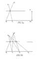
- FIGS. 1 a and 1 bshow an observer's eyes seeing half of the respective image through each eye, and the other half of each respective image, respectively.
- FIGS. 2 a , 2 b and 2 cshow the use of three phases.
- FIGS. 3 a and 3 bshow the observer far and near, respectively, from the shutter.
- FIG. 4shows the stripes vary in width in a perspective linear pattern.
- FIGS. 5 a and 5 bshow the processes of the present invention after 1 iteration and 3 iterations, respectively.
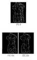
- FIGS. 6 a and 6 bare computer generated illustrations which show separate left and right images, respectively.
- FIGS. 7 a , 7 b and 7 care computer generated illustrations which show the red, green and blue components, respectively.
- FIG. 8is a flow chart of the present invention.
- FIG. 9is a computer generated illustration which shows an image displayed on an unenhanced monitor.
- FIGS. 10 a and 10 bare computer generated illustrations which show what the left and right eyes, respectively, would see with the present invention in place.
- FIG. 11is a computer generated illustration which shows the apparatus of the present invention.
- FIGS. 12 a and 12 bare computer generated illustrations which show a pi-cell.
- FIG. 13shows a stereo embodiment of the present invention.
- an apparatus 10 for displaying an image to an observercomprises a display screen 12 upon which stripes of the image appear in at least three distinct phases.
- the apparatus 10comprises a light blocking shutter 14 disposed in front of the display screen 12 forming a stripe pattern which lets through only 1 ⁇ 3 of each stripe of the image on the display screen 12 during each of the at least three distinct phases.
- the apparatus 10comprises a computer 16 connected to the display screen 12 and the light blocking shutter 14 which changes the phases so in each phase the stripe pattern is shifted laterally, which renders two 3D scenes corresponding to the eyes of the observer, which produces a proper left/right orientation pattern for each of the three phases and which interleaves the left/right orientations into three successive time phases as red, green and blue, respectively.
- the apparatus 10comprises an eye tracker 18 for identifying the locations of the observers' eyes and providing the location to the computer 16 .
- the display screen 12includes a rear projection screen 20 .
- the display screen 12preferably includes a field programmable gate array 22 in communication with the projection screen and the shutter which synchronizes the phases between the shutter and the projection screen.
- the display screen 12includes a digital light processor projector 24 in communication with the array and the projection screen which displays the three phases of images sequentially and controls the timing of the phases.
- the display screen 12preferably includes a ferroelectric liquid crystal 26 in communication with the array, the light processor, and the projection screen which shutters the start and stop of each phase.
- the shutterincludes a pi-cell.
- the present inventionpertains to a method for displaying an image to an observer.
- the methodcomprises the steps of identifying locations of the observer's eyes with an eye tracker 18 .
- There is the step of forming a stripe patternwhich lets through only 1 ⁇ 3 of each stripe of the image on the display screen 12 during each of the at least three distinct phases with a light blocking shutter 14 disposed in front of the screen.
- the forming stepincludes the step of encoding into 3 1-dimensional bit-maps the three phases of stripe for the light shutter, each indicating an on-off pattern for shutter micro-stripes at one of the three phases; and sending these bit-maps to a field programmable gate array 22 of the display screen 12 .
- the forming steppreferably includes the step of sending with the field programmable gate array 22 the three bit-patterns to a pi-cell light shutter in rotating sequence.
- the forming stepincludes the step of controlling with a digital light processor projector 24 of the display screen 12 timing of the rotating sequence of the three-bit patterns to the pi-cell.
- the displaying steppreferably includes the step of displaying with the digital light processor projector 24 the three image phases in succession.
- a modified parallax barrierwas created that combines spatial multiplexing and temporal multiplexing. Since no fixed parallax barrier geometry could accommodate arbitrary observer position and orientation, a dynamically varying parallax barrier was created, one that continually changes the width and positions of its stripes as the observer moves.
- the use of a virtual dynamic parallax barrieris reminiscent of work by [J. R. Moore, N. A. Dodgson, A. R. L. Travis and S. R. Lang. Time-Multiplexed Color Autostereoscopic Display. Proc. SPIE 2653, SPIE Symposium on Stereoscopic Displays and Applications VII, San Jose, Calif., Jan. 28–Feb. 2, 1996, pp. 10–19 and J.
- Each dynamic stripeneeds to be highly variable in its width, in order to accommodate many different positions and orientations of the observer. For this reason, the dynamic stripes were made rather large, and use a correspondingly large gap between the display screen 12 and the light-blocking parallax barrier. Because the stripes are large enough to be easily visible, they were needed to be made somehow unnoticeable. To do this, they were rapidly animated in a lateral direction. The observer then cannot perceive the individual stripes, just as a passenger in a car speeding alongside a picket fence cannot see the individual fence posts.
- This large-stripe approachrequires each stripe to be composed from some number of very slender microstripes, each of which is an individually switchable liquid crystal 26 display element.
- a dynamic parallax barrierwas used consisting of very large stripes, which are made out of many slender ones, and these large stripes are moved so rapidly across the image that the observer cannot perceive them.
- a temporally multiplexed systemcould be made from just two alternating phases.
- Parallax barrier systemsdepend on the distance E between an observer's two eyes (generally about 2.5 inches).
- a display screen 12 D inches away from the observershowed alternating stripes of a left and a right image.
- a light-blocking shutterwere placed G inches in front of this display screen 12 in a “picket fence” stripe pattern.
- each shutter stripewere chosen as E*G/D, and the width of each image stripe as E*G/(D ⁇ G), then during phase 1 the observer's left eye would be able to see half of one image through the clear stripes, and the observer's right eye would be able to see half of the other image through the clear stripes [ FIG. 1 a ]. If the light-blocking shutter were then flipped, and the display screen 12 pattern simultaneously changed, then the observer would see the remainder of each respective image [ FIG. 1 b ]. If this flipping were done fast enough, then the observer would perceive two complete independent images, each visible only to one eye. The problem with this scenario is that the observer would need to be in precisely the correct position; the slightest deviation to the left or right would result in the wrong eye seeing a sliver of the wrong image.
- the stripesare animated in three phases.
- the light-blocking shutterlets through only one third of each stripe.
- the stripe patternis shifted laterally. Over the course of three phases, the observer's left eye sees one entire image, and the observer's eye sees a different entire image.
- the use of three phasesguarantees that there is room for error in the observer's lateral position [ FIGS. 2 a , 2 b , 2 c ].
- the observercan be at a wide range of distances, since the stripe width can always be varied so as to equal E*G/D, as described above.
- FIG. 3 ashows the observer relatively far;
- FIG. 3 bshows the observer much closer.
- Microstripe resolutionputs a practical upper limit on the observer distance, since the stripes become narrower as the observer's distance to the screen increases.
- This upper limitincreases linearly both with the gap between the display and shutter, and with the shutter resolution. In practice, these have been set so as to be able to handle an observer up to about five feet away.
- FIGS. 5 a , 5 bshow how to construct a sequence of stripe positions from two eye positions (shown as a green and red dot, respectively), a display surface (shown as the bottom of the two horizontal lines) and a shutter surface (shown as the top of the two horizontal lines).
- a display surfaceshown as the bottom of the two horizontal lines
- a shutter surfaceshown as the top of the two horizontal lines.
- the even termslocate the centers of those portions of the image visible from the right eye
- the odd termslocate the centers of those portions of the image visible from the left eye.
- the openings in the shutterare centered at f ⁇ 1 q ( x 0 ), f ⁇ 1 q ( x 2 ), etc.
- a custom pi-cell liquid crystal 26 screen built to our specifications by LXDwas used, which was driven from power ICs mounted on a custom-made Printed Circuit Board (PCB).
- PCBPrinted Circuit Board
- FPGAField Programmable Gate Array
- the steps to display a frameare:
- Steps (5) through (9) aboveare part of the “real-time subsystem” which is monitored by the FPGA. These parts of the process are monitored continuously by the FPGA to synchronize all the events which must occur simultaneously 180 times per second.
- OpenGLis used to encode the red/green/blue sub-images which the DLP projector will turn into time sequential phases. To do this, first render the compute separate left and right images in OpenGL, into off-screen buffers, as shown in FIGS. 6 a , 6 b.
- FIGS. 7 a , 7 b , 7 care computer generated illustrations.
- FIG. 9is a computer generated illustration.
- each of the observer's eyeswill reconstruct a complete image from a single viewpoint. If the DLP projector's color wheel were engaged, then the left and right eyes would see FIG. 10 a and FIG. 10 b , respectively, which are computer generated illustrations. With the color wheel removed, each of the observer's eyes simply sees the correct stereo component image of FIG. 6 a and FIG. 6 b , respectively.
- the real-time subsystemmaintains a more stringent schedule: a synchronous 180 Hz cycle.
- the pattern on the light-shutterneeds to switch at the same moment that the DLP projector begins its red, green, or blue component.
- This timing taskis handled by the FPGA, which reads a signal produced by the projector every time it the color wheel cycles (about once every 1/180 second) and responds by cycling the light shutter pattern.
- the FPGAmodulates a ferro-electric optical switch which is mounted in front of the projector lens.
- the main CPUis not involved at all in this fine-grained timing.
- the only tasks required of the CPUare to produce left/right images, to interleave them to create a red/green/blue composite, and to put the result into an on-screen frame buffer, ideally (but not critically) at 60 frames per second.
- FIG. 11is a computer 16 generated illustration. Each is described in some detail.
- an ISA interface boardwas built with a non volatile Xilinx 95C108 PLD and a reconfigurable Xilinx XC4005E FPGA.
- the PLDis used to generate the ISA Bus Chip Select signals and to reprogram the FPGA.
- the XC4005Eis large enough to contain six 256 bit Dual Ported RAMs (to double buffer the shutter masks needed for our three phases), the ISA Bus logic, and all the hardware needed to process the DLP signals and drive the pi-cell.
- this chipWhen loaded with the three desired patterns from the main CPU, this chip continually monitors the color wheel signals from the DLP projector. Each time it detects a change from red to green, green to blue, or blue to red, it sends the proper signals to the Supertex HV57708 high voltage Serial to parallel converters mounted on the Pi-cell, switching each of the light shutter's 256 microstripes on or off.
- a standard twisted nematic liquid crystal 26 display(such as is widely used in notebook computers) does not have the switching speed needed; requiring about 20 msec to relax from its on state to its off state after charge has been removed. Instead, a pi-cell is used, which is a form of liquid crystal 26 material in which the crystals twist by 180° (hence the name) rather than that 90° twist used for twisted nematic LC displays.
- Pi-cellshave not been widely used partly because they tend to be bistable—they tend to snap to either one polarization or another This makes it difficult to use them for gray scale modulation. On the other hand, they will relax after a charge has been removed far more rapidly than will twisted nematic—a pi-cell display can be driven to create a reasonable square wave at 200 Hz. This is precisely the characteristic needed—an on-off light blocking device that can be rapidly switched. Cost would be comparable to that of twisted nematic LC displays, if produced at comparable quantities.
- FIG. 12 a and FIG. 12 bwhich are computer generated illustrations, show the pi-cell device that was manufactured by LXD.
- the image to the leftshows the size of the screen, the close-up image the right shows the individual microstripes and edge connectors.
- the active areais 14′′ ⁇ 12′′, and the microstripes run vertically, 20 per inch.
- the microstripe densitycould easily have exceeded 100 per inch, but the density chosen required to drive only 256 microstripes, and was sufficient for a first prototype.
- Edge connectors for the even microstripesrun along the bottom; edge connectors for the odd microstripes run along the top. Four power chips to maintain the required 40 volts, each with 64 pin-outs were used.
- a ferro-electric liquid crystal 26will switch even faster than will a pi-cell, since it has a natural bias that allows it to be actively driven from the on-state to the off-state and back again.
- a ferro-electric elementcan be switched in 70 microseconds.
- ferro-electric elementsare very delicate and expensive to manufacture at large scales, and would therefore be impractical to use as the light shutter. However, at small sizes they are quite practical and robust to work with.
- a small ferro-electric switchwas used over the projector lens, manufactured by Displaytech, to provide a sharper cut-off between the three phases of the shutter sequence. This element is periodically closed between the respective red, green, and blue phases of the DLP projector's cycle. While the FLC is closed, the pi-cell microstripes transitions (which require about 1.2 ms) are effected.
- a system based on this principlesends a small infrared light from the direction of a camera during only the even video fields.
- the difference image between the even and odd video fieldswill show only two glowing spots, locating the observer's left and right eyes, respectively.
- the systemis able to simultaneously capture two parallax displaced images of the glowing eye spots. The lateral shift between the respective eye spots in these two images is measured, to calculate the distance of each eye.
- a Kalman filter[M. Grewal, A. Andrews, Kalman Filtering: Theory and Practice, Prentice Hall, 1993, incorporated by reference herein] is used to smooth out these results and to interpolate eye position during the intermediate fields.
- a number of groupsare planning commercial deployment of retroreflective-based tracking in some form, including IBM.
- the DynaSite from Origin Systemswere use, which requires the user to wear a retroreflective dot, but does not block the user's line of sight.
- the user trackingprovides as a pair of 3D points, one for each eye.
- this informationis used in three ways.
- Each of these pointsis used by OpenGL as the eye point from which to render the virtual scene into an offscreen buffer;
- the proper succession lateral locations for left/right image interleavingis calculated, which is used to convert the left/right offscreen images into the three temporally phased images;
- the proper positions for the light shutter transitionsare calculated.
- This informationis converted to three one dimensional bit-maps, each indicating an on-off pattern for the shutter micro-stripes at one of the three phases.
- This informationis sent to the FPGA, which then sends the proper pattern to the light shutter every 1/180 second, synchronously with the three phases of the DLP projector.
- the goals of the present invention of the systemwere (i) low latency and (ii) absence of artifacts.
- the most important question to answeris: “does it work?” The answer is yes.
- the experienceis most compelling when objects appear to lie near the distance of the display screen 12 , so that stereo disparity is reasonably close to focus (which is always in the plane of the projection screen).
- the experienceis compelling; as an observer looks around an object, it appears to float within the viewing volume. The observer can look around the object, and can position himself or herself at various distances from the screen as well. Special eyewear is not required.
- the software-implemented rendererdid not achieve a consistent 60 frames per second, but rather something closer to 30 frames per second. In practice this meant that if the observer darted his/her head about too quickly, the tracker could not properly feed the display subsystem when the user moved his/her head rapidly.
- the more critical issueis that of position-error based artifacts. It is crucial for the system to be calibrated accurately, so that it has a correct internal model of the observer's position. If the tracker believes the observer is too near or far away, then it will produce the wrong size of stripes, which will appear to the observer as vertical stripe artifacts (due to the wrong eye seeing the wrong image) near the sides of the screen. If the tracker believes the observer is displaced to the left or right, then this striping pattern will cover the entire display. A careful one-time calibration removed all such artifacts. This emphasizes the need for good eye position tracking.
- This display platformcan be used for teleconferencing. With a truly non-invasive stereoscopic display, two people having a video conversation can perceive the other as though looking across a table. Each person's image is transmitted to the other via a video camera that also captures depth [T. Kanade, et al. Development of a Video Rate Stereo Machine. Proc. of International Robotics and Systems Conference (IROS-95), Pittsburgh, Pa., Aug. 7–9, 1995, incorporated by reference herein]. At the recipient end, movements of the observer's head are tracked, and the transmitted depth-enhanced image is interpolated to create a proper view from the observer's left and right eyes, as in [S. Chen and L. Williams. View Interpolation for Image Synthesis. Computer Graphics (SIGGRAPH 93 Conference Proc.) p. 279–288, incorporated by reference herein]. Head movements by each participant reinforce the sense of presence and solidity of the other, and proper eye contact is always maintained.
- An implementation of an API for game developersis possible so that users of accelerator boards for two-person games can make use of the on-board two-view hardware support provided in those boards to simultaneously accelerate left and right views in the display. Variants of this system for two observers are also possible.
- FIG. 13shows two cameras with active IR illumination to detect a “red-eye” image and subtract it from a “normal image”.
- IR polarizersseparate the optical illumination paths of the two cameras, making the system far less prone to errors in a stereo mode.
Landscapes
- Engineering & Computer Science (AREA)
- Multimedia (AREA)
- Signal Processing (AREA)
- Physics & Mathematics (AREA)
- General Physics & Mathematics (AREA)
- Optics & Photonics (AREA)
Abstract
Description
- 1. Draw a line from xnon the display, through the shutter, to the right eye;
- 2. Draw a line from the left eye, through the shutter, to xn+1on the display;
- 3. Iterate
fp(x)=pxpy−1+x(1−py−1)
fp−1(x)=(x−pxpy−1)/(1−py−1)
xn+1=fq−1(fp(xn))
which expands out to:
(pxpy−1+x(1−py−1)−qxqy−1)/(1−qy−1)
A=x(1−py−1)/(1−qy−1)
B=(pxpy−1−qxqy−1)/(1−qy−1)
x0=0x1=Bx2=AB+B
x3=A2B+AB+B
xn=B(An−1+ . . . +A+1)
f−1q(x0),f−1q(x2), etc.
- (1) An
eye tracker 18 locates the observer's eyes, and sends this information to the CPU. - (2) The main CPU uses the
eye tracker 18 info to render two 3D scenes: one as seen from each eye. - (3) The main CPU also uses the
eye tracker 18 info to compute, for each of three phases, the proper left/right alternation pattern. These are interleaved into three successive time phases as red, green, and blue, respectively. - (4) The main CPU also uses the eye info to compute the three phases of stripe on the light shutter. These are encoded into three one-dimensional bit-maps, each indicating an on-off pattern for the shutter micro-stripes at one of the three phases. These bit-maps are shipped to the FPGA.
- (5) The FPGA sends the three bit-patterns to the pi-cell light shutter in rotating sequence, every 1/180 second. The timing for this is controlled by the DLP projector, which produces a signal every time its color wheel advances.
- (6) The DLP projector displays the three image phases in succession. The color wheel on the projector is removed, so that each of the red, green, and blue components displays as a gray scale image.
- (7) The FLC element is modulated by the FPGA to block the light from the DLP projector lens in a 180 Hz square wave pattern. This allows finer control over timing.
- (8) A rear projection screen20 (RPS) diffuses the image from the DLP projector.
- (9) The pi-cell light shutter positioned in front of the RPS displays a different horizontally varying on-off pattern every 1/180 second.
Claims (21)
Priority Applications (2)
| Application Number | Priority Date | Filing Date | Title |
|---|---|---|---|
| US09/909,927US7239293B2 (en) | 1998-01-21 | 2001-07-20 | Autostereoscopic display |
| US11/823,805US20080024598A1 (en) | 2000-07-21 | 2007-06-28 | Autostereoscopic display |
Applications Claiming Priority (4)
| Application Number | Priority Date | Filing Date | Title |
|---|---|---|---|
| US09/010,313US6061084A (en) | 1998-01-21 | 1998-01-21 | Displayer and a method for displaying |
| US09/312,998US6239830B1 (en) | 1998-01-21 | 1999-05-17 | Displayer and method for displaying |
| US21984500P | 2000-07-21 | 2000-07-21 | |
| US09/909,927US7239293B2 (en) | 1998-01-21 | 2001-07-20 | Autostereoscopic display |
Related Parent Applications (1)
| Application Number | Title | Priority Date | Filing Date |
|---|---|---|---|
| US09/312,998Continuation-In-PartUS6239830B1 (en) | 1998-01-21 | 1999-05-17 | Displayer and method for displaying |
Related Child Applications (1)
| Application Number | Title | Priority Date | Filing Date |
|---|---|---|---|
| US11/823,805ContinuationUS20080024598A1 (en) | 2000-07-21 | 2007-06-28 | Autostereoscopic display |
Publications (2)
| Publication Number | Publication Date |
|---|---|
| US20020015007A1 US20020015007A1 (en) | 2002-02-07 |
| US7239293B2true US7239293B2 (en) | 2007-07-03 |
Family
ID=26914312
Family Applications (1)
| Application Number | Title | Priority Date | Filing Date |
|---|---|---|---|
| US09/909,927Expired - Fee RelatedUS7239293B2 (en) | 1998-01-21 | 2001-07-20 | Autostereoscopic display |
Country Status (1)
| Country | Link |
|---|---|
| US (1) | US7239293B2 (en) |
Cited By (53)
| Publication number | Priority date | Publication date | Assignee | Title |
|---|---|---|---|---|
| US20080024598A1 (en)* | 2000-07-21 | 2008-01-31 | New York University | Autostereoscopic display |
| US20090201363A1 (en)* | 2006-07-24 | 2009-08-13 | Seefront Gmbh | Autostereoscopic system |
| US20090201362A1 (en)* | 2008-02-13 | 2009-08-13 | Samsung Electronics Co., Ltd. | Autostereoscopic display system |
| US20090219253A1 (en)* | 2008-02-29 | 2009-09-03 | Microsoft Corporation | Interactive Surface Computer with Switchable Diffuser |
| US20090282429A1 (en)* | 2008-05-07 | 2009-11-12 | Sony Ericsson Mobile Communications Ab | Viewer tracking for displaying three dimensional views |
| US20100039698A1 (en)* | 2008-08-14 | 2010-02-18 | Real D | Autostereoscopic display system with efficient pixel layout |
| US20100097545A1 (en)* | 2008-10-14 | 2010-04-22 | Real D | Lenticular display systems with offset color filter array |
| US20100171811A1 (en)* | 2006-04-21 | 2010-07-08 | Expert Treuhand Gmbh | Method and device for the creation of pseudo-holographic images |
| US20100253916A1 (en)* | 2009-04-03 | 2010-10-07 | Chunyu Gao | Retro-Reflective Light Diffusing Display Systems |
| US20100253915A1 (en)* | 2009-04-03 | 2010-10-07 | Chunyu Gao | Retro-Reflective Light Diffusing Display Systems |
| US20100253917A1 (en)* | 2009-04-03 | 2010-10-07 | Chunyu Gao | Aerial Three-Dimensional Image Display Systems |
| US20100295958A1 (en)* | 2009-05-20 | 2010-11-25 | Sony Ericsson Mobile Communications Ab | Portable electronic apparatus including a display and method for controlling such an apparatus |
| US20110012896A1 (en)* | 2009-06-22 | 2011-01-20 | Ji Maengsob | Image display apparatus, 3d glasses, and method for operating the image display apparatus |
| US20120194514A1 (en)* | 2010-05-28 | 2012-08-02 | Tatsumi Sakaguchi | Image processing apparatus and method, and program |
| US8502816B2 (en) | 2010-12-02 | 2013-08-06 | Microsoft Corporation | Tabletop display providing multiple views to users |
| US8570357B2 (en) | 2011-04-29 | 2013-10-29 | Hewlett-Packard Development Company, L.P. | Systems and methods for reducing video crosstalk |
| US20140028812A1 (en)* | 2012-07-27 | 2014-01-30 | Kabushiki Kaisha Toshiba | Three-dimensional video display apparatus |
| US8704822B2 (en) | 2008-12-17 | 2014-04-22 | Microsoft Corporation | Volumetric display system enabling user interaction |
| US8885882B1 (en) | 2011-07-14 | 2014-11-11 | The Research Foundation For The State University Of New York | Real time eye tracking for human computer interaction |
| US9137524B2 (en) | 2012-11-27 | 2015-09-15 | Qualcomm Incorporated | System and method for generating 3-D plenoptic video images |
| US9265458B2 (en) | 2012-12-04 | 2016-02-23 | Sync-Think, Inc. | Application of smooth pursuit cognitive testing paradigms to clinical drug development |
| US9380976B2 (en) | 2013-03-11 | 2016-07-05 | Sync-Think, Inc. | Optical neuroinformatics |
| US9678267B2 (en) | 2012-05-18 | 2017-06-13 | Reald Spark, Llc | Wide angle imaging directional backlights |
| US9709723B2 (en) | 2012-05-18 | 2017-07-18 | Reald Spark, Llc | Directional backlight |
| US9739928B2 (en) | 2013-10-14 | 2017-08-22 | Reald Spark, Llc | Light input for directional backlight |
| US9740034B2 (en) | 2013-10-14 | 2017-08-22 | Reald Spark, Llc | Control of directional display |
| US9835792B2 (en) | 2014-10-08 | 2017-12-05 | Reald Spark, Llc | Directional backlight |
| US9872007B2 (en) | 2013-06-17 | 2018-01-16 | Reald Spark, Llc | Controlling light sources of a directional backlight |
| US9910207B2 (en) | 2012-05-18 | 2018-03-06 | Reald Spark, Llc | Polarization recovery in a directional display device |
| US10054732B2 (en) | 2013-02-22 | 2018-08-21 | Reald Spark, Llc | Directional backlight having a rear reflector |
| US10228505B2 (en) | 2015-05-27 | 2019-03-12 | Reald Spark, Llc | Wide angle imaging directional backlights |
| CN109597210A (en)* | 2017-09-20 | 2019-04-09 | 天马日本株式会社 | Display device |
| US10321123B2 (en) | 2016-01-05 | 2019-06-11 | Reald Spark, Llc | Gaze correction of multi-view images |
| US10330843B2 (en) | 2015-11-13 | 2019-06-25 | Reald Spark, Llc | Wide angle imaging directional backlights |
| US10356383B2 (en) | 2014-12-24 | 2019-07-16 | Reald Spark, Llc | Adjustment of perceived roundness in stereoscopic image of a head |
| US10359561B2 (en) | 2015-11-13 | 2019-07-23 | Reald Spark, Llc | Waveguide comprising surface relief feature and directional backlight, directional display device, and directional display apparatus comprising said waveguide |
| US10359560B2 (en) | 2015-04-13 | 2019-07-23 | Reald Spark, Llc | Wide angle imaging directional backlights |
| US10365426B2 (en) | 2012-05-18 | 2019-07-30 | Reald Spark, Llc | Directional backlight |
| US10401638B2 (en) | 2017-01-04 | 2019-09-03 | Reald Spark, Llc | Optical stack for imaging directional backlights |
| US10408992B2 (en) | 2017-04-03 | 2019-09-10 | Reald Spark, Llc | Segmented imaging directional backlights |
| US10425635B2 (en) | 2016-05-23 | 2019-09-24 | Reald Spark, Llc | Wide angle imaging directional backlights |
| US10459321B2 (en) | 2015-11-10 | 2019-10-29 | Reald Inc. | Distortion matching polarization conversion systems and methods thereof |
| US10475418B2 (en) | 2015-10-26 | 2019-11-12 | Reald Spark, Llc | Intelligent privacy system, apparatus, and method thereof |
| US10740985B2 (en) | 2017-08-08 | 2020-08-11 | Reald Spark, Llc | Adjusting a digital representation of a head region |
| US10802356B2 (en) | 2018-01-25 | 2020-10-13 | Reald Spark, Llc | Touch screen for privacy display |
| US11067736B2 (en) | 2014-06-26 | 2021-07-20 | Reald Spark, Llc | Directional privacy display |
| US11079619B2 (en) | 2016-05-19 | 2021-08-03 | Reald Spark, Llc | Wide angle imaging directional backlights |
| US11115647B2 (en) | 2017-11-06 | 2021-09-07 | Reald Spark, Llc | Privacy display apparatus |
| US11287878B2 (en) | 2012-05-18 | 2022-03-29 | ReaID Spark, LLC | Controlling light sources of a directional backlight |
| US11821602B2 (en) | 2020-09-16 | 2023-11-21 | Reald Spark, Llc | Vehicle external illumination device |
| US11908241B2 (en) | 2015-03-20 | 2024-02-20 | Skolkovo Institute Of Science And Technology | Method for correction of the eyes image using machine learning and method for machine learning |
| US11966049B2 (en) | 2022-08-02 | 2024-04-23 | Reald Spark, Llc | Pupil tracking near-eye display |
| US12282168B2 (en) | 2022-08-11 | 2025-04-22 | Reald Spark, Llc | Anamorphic directional illumination device with selective light-guiding |
Families Citing this family (22)
| Publication number | Priority date | Publication date | Assignee | Title |
|---|---|---|---|---|
| AU2001287094A1 (en)* | 2000-09-07 | 2002-03-22 | Actuality Systems, Inc. | Graphics memory system for volumetric displays |
| TW200527114A (en)* | 2003-12-16 | 2005-08-16 | Koninkl Philips Electronics Nv | Brightness regulation in LCD projection systems |
| GB0403932D0 (en)* | 2004-02-21 | 2004-03-24 | Koninkl Philips Electronics Nv | Improving image quality in a 3D image display device |
| US8300043B2 (en) | 2004-06-24 | 2012-10-30 | Sony Ericsson Mobile Communications AG | Proximity assisted 3D rendering |
| KR100649251B1 (en)* | 2004-06-30 | 2006-11-24 | 삼성에스디아이 주식회사 | 3D image display device and driving method thereof |
| KR101112735B1 (en)* | 2005-04-08 | 2012-03-13 | 삼성전자주식회사 | 3D display apparatus using hybrid tracking system |
| KR101265893B1 (en)* | 2005-06-07 | 2013-05-20 | 리얼디 인크. | Controlling the angular extent of autostereoscopic viewing zones |
| CN100374907C (en)* | 2006-01-27 | 2008-03-12 | 张凯明 | Naked eye visible stereo image display device with liquid crystal shutter optical screen and display method thereof |
| US8284204B2 (en)* | 2006-06-30 | 2012-10-09 | Nokia Corporation | Apparatus, method and a computer program product for providing a unified graphics pipeline for stereoscopic rendering |
| KR101652471B1 (en)* | 2009-06-16 | 2016-08-30 | 삼성전자주식회사 | Display device and method thereof |
| KR20120084775A (en)* | 2009-10-30 | 2012-07-30 | 휴렛-팩커드 디벨롭먼트 컴퍼니, 엘.피. | Stereo display systems |
| CN101795420B (en)* | 2010-04-07 | 2012-12-26 | 昆山龙腾光电有限公司 | Stereo image displaying system and control method thereof |
| KR101665567B1 (en)* | 2010-05-20 | 2016-10-12 | 삼성전자주식회사 | Temporal interpolation of three dimension depth image method and apparatus |
| KR101729556B1 (en)* | 2010-08-09 | 2017-04-24 | 엘지전자 주식회사 | A system, an apparatus and a method for displaying a 3-dimensional image and an apparatus for tracking a location |
| KR101695819B1 (en)* | 2010-08-16 | 2017-01-13 | 엘지전자 주식회사 | A apparatus and a method for displaying a 3-dimensional image |
| US8820937B2 (en)* | 2010-08-17 | 2014-09-02 | Lc-Tec Displays Ab | Optical polarization state modulator assembly for use in stereoscopic three-dimensional image projection system |
| CN102156565B (en)* | 2010-12-31 | 2014-11-05 | 深圳超多维光电子有限公司 | Display equipment and method, and naked eye three-dimensional display device |
| FR2971064B1 (en)* | 2011-01-31 | 2015-12-18 | Wysips | PARALLAX BARRIER DISPLAY SCREEN WITH INTEGRATED PHOTOVOLTAIC CELLS AND METHOD FOR MANUFACTURING THE SAME |
| US9285586B2 (en) | 2011-05-13 | 2016-03-15 | Sony Corporation | Adjusting parallax barriers |
| KR101970577B1 (en)* | 2013-04-09 | 2019-04-19 | 엘지디스플레이 주식회사 | Stereoscopic display device and eye-tracking method thereof |
| US10247941B2 (en)* | 2015-01-19 | 2019-04-02 | Magna Electronics Inc. | Vehicle vision system with light field monitor |
| US9690110B2 (en)* | 2015-01-21 | 2017-06-27 | Apple Inc. | Fine-coarse autostereoscopic display |
Citations (10)
| Publication number | Priority date | Publication date | Assignee | Title |
|---|---|---|---|---|
| US5231521A (en)* | 1989-10-30 | 1993-07-27 | The University Of Colorado Foundation, Inc. | Chiral smectic liquid crystal polarization interference filters |
| US5712732A (en)* | 1993-03-03 | 1998-01-27 | Street; Graham Stewart Brandon | Autostereoscopic image display adjustable for observer location and distance |
| US5808599A (en)* | 1993-05-05 | 1998-09-15 | Pierre Allio | Autostereoscopic video device and system |
| US5825337A (en)* | 1993-11-19 | 1998-10-20 | Asd (Holdings) Ltd | Color autostereoscopic display |
| US5880704A (en)* | 1993-09-24 | 1999-03-09 | Fujitsu Limited | Three-dimensional image display device and recording device |
| US5886675A (en)* | 1995-07-05 | 1999-03-23 | Physical Optics Corporation | Autostereoscopic display system with fan-out multiplexer |
| US6049424A (en)* | 1995-11-15 | 2000-04-11 | Sanyo Electric Co., Ltd. | Three dimensional display device |
| US6057811A (en)* | 1993-09-28 | 2000-05-02 | Oxmoor Corporation | 3-D glasses for use with multiplexed video images |
| US6377229B1 (en)* | 1998-04-20 | 2002-04-23 | Dimensional Media Associates, Inc. | Multi-planar volumetric display system and method of operation using three-dimensional anti-aliasing |
| US6816158B1 (en)* | 1998-10-30 | 2004-11-09 | Lemelson Jerome H | Three-dimensional display system |
- 2001
- 2001-07-20USUS09/909,927patent/US7239293B2/ennot_activeExpired - Fee Related
Patent Citations (10)
| Publication number | Priority date | Publication date | Assignee | Title |
|---|---|---|---|---|
| US5231521A (en)* | 1989-10-30 | 1993-07-27 | The University Of Colorado Foundation, Inc. | Chiral smectic liquid crystal polarization interference filters |
| US5712732A (en)* | 1993-03-03 | 1998-01-27 | Street; Graham Stewart Brandon | Autostereoscopic image display adjustable for observer location and distance |
| US5808599A (en)* | 1993-05-05 | 1998-09-15 | Pierre Allio | Autostereoscopic video device and system |
| US5880704A (en)* | 1993-09-24 | 1999-03-09 | Fujitsu Limited | Three-dimensional image display device and recording device |
| US6057811A (en)* | 1993-09-28 | 2000-05-02 | Oxmoor Corporation | 3-D glasses for use with multiplexed video images |
| US5825337A (en)* | 1993-11-19 | 1998-10-20 | Asd (Holdings) Ltd | Color autostereoscopic display |
| US5886675A (en)* | 1995-07-05 | 1999-03-23 | Physical Optics Corporation | Autostereoscopic display system with fan-out multiplexer |
| US6049424A (en)* | 1995-11-15 | 2000-04-11 | Sanyo Electric Co., Ltd. | Three dimensional display device |
| US6377229B1 (en)* | 1998-04-20 | 2002-04-23 | Dimensional Media Associates, Inc. | Multi-planar volumetric display system and method of operation using three-dimensional anti-aliasing |
| US6816158B1 (en)* | 1998-10-30 | 2004-11-09 | Lemelson Jerome H | Three-dimensional display system |
Cited By (83)
| Publication number | Priority date | Publication date | Assignee | Title |
|---|---|---|---|---|
| US20080024598A1 (en)* | 2000-07-21 | 2008-01-31 | New York University | Autostereoscopic display |
| US20140152782A1 (en)* | 2006-04-21 | 2014-06-05 | Expert Treuhand Gmbh | Method and device for the creation of pseudo-holographic images |
| US8633967B2 (en)* | 2006-04-21 | 2014-01-21 | Expert Treuhand Gmbh | Method and device for the creation of pseudo-holographic images |
| US20100171811A1 (en)* | 2006-04-21 | 2010-07-08 | Expert Treuhand Gmbh | Method and device for the creation of pseudo-holographic images |
| US9083963B2 (en)* | 2006-04-21 | 2015-07-14 | Expert Treuhand Gmbh | Method and device for the creation of pseudo-holographic images |
| US20090201363A1 (en)* | 2006-07-24 | 2009-08-13 | Seefront Gmbh | Autostereoscopic system |
| US8077195B2 (en)* | 2006-07-24 | 2011-12-13 | Seefront Gmbh | Autostereoscopic system |
| US20090201362A1 (en)* | 2008-02-13 | 2009-08-13 | Samsung Electronics Co., Ltd. | Autostereoscopic display system |
| US8587642B2 (en)* | 2008-02-13 | 2013-11-19 | Samsung Electronics Co., Ltd. | Autostereoscopic display system |
| KR101451565B1 (en)* | 2008-02-13 | 2014-10-16 | 삼성전자 주식회사 | Autostereoscopic display system |
| US20090219253A1 (en)* | 2008-02-29 | 2009-09-03 | Microsoft Corporation | Interactive Surface Computer with Switchable Diffuser |
| US20090282429A1 (en)* | 2008-05-07 | 2009-11-12 | Sony Ericsson Mobile Communications Ab | Viewer tracking for displaying three dimensional views |
| US20100039698A1 (en)* | 2008-08-14 | 2010-02-18 | Real D | Autostereoscopic display system with efficient pixel layout |
| US8542432B2 (en) | 2008-08-14 | 2013-09-24 | Reald Inc. | Autostereoscopic display system with efficient pixel layout |
| US20100097545A1 (en)* | 2008-10-14 | 2010-04-22 | Real D | Lenticular display systems with offset color filter array |
| US8704822B2 (en) | 2008-12-17 | 2014-04-22 | Microsoft Corporation | Volumetric display system enabling user interaction |
| US20100253917A1 (en)* | 2009-04-03 | 2010-10-07 | Chunyu Gao | Aerial Three-Dimensional Image Display Systems |
| US7993016B2 (en) | 2009-04-03 | 2011-08-09 | Seiko Epson Corporation | Retro-reflective light diffusing display systems |
| US8328360B2 (en) | 2009-04-03 | 2012-12-11 | Seiko Epson Corporation | Retro-reflective light diffusing autostereoscopic 3D display systems |
| US20100253915A1 (en)* | 2009-04-03 | 2010-10-07 | Chunyu Gao | Retro-Reflective Light Diffusing Display Systems |
| US8287127B2 (en) | 2009-04-03 | 2012-10-16 | Seiko Epson Corporation | Aerial three-dimensional image display systems |
| US20100253916A1 (en)* | 2009-04-03 | 2010-10-07 | Chunyu Gao | Retro-Reflective Light Diffusing Display Systems |
| US20100295958A1 (en)* | 2009-05-20 | 2010-11-25 | Sony Ericsson Mobile Communications Ab | Portable electronic apparatus including a display and method for controlling such an apparatus |
| US8179449B2 (en)* | 2009-05-20 | 2012-05-15 | Sony Ericsson Mobile Communications Ab | Portable electronic apparatus including a display and method for controlling display content based on movement of the display and user position |
| US20110012896A1 (en)* | 2009-06-22 | 2011-01-20 | Ji Maengsob | Image display apparatus, 3d glasses, and method for operating the image display apparatus |
| US9210407B2 (en)* | 2010-05-28 | 2015-12-08 | Sony Corporation | Image processing apparatus and method, and program |
| US20120194514A1 (en)* | 2010-05-28 | 2012-08-02 | Tatsumi Sakaguchi | Image processing apparatus and method, and program |
| US8502816B2 (en) | 2010-12-02 | 2013-08-06 | Microsoft Corporation | Tabletop display providing multiple views to users |
| US8570357B2 (en) | 2011-04-29 | 2013-10-29 | Hewlett-Packard Development Company, L.P. | Systems and methods for reducing video crosstalk |
| US8885882B1 (en) | 2011-07-14 | 2014-11-11 | The Research Foundation For The State University Of New York | Real time eye tracking for human computer interaction |
| US9910207B2 (en) | 2012-05-18 | 2018-03-06 | Reald Spark, Llc | Polarization recovery in a directional display device |
| US11681359B2 (en) | 2012-05-18 | 2023-06-20 | Reald Spark, Llc | Controlling light sources of a directional backlight |
| US9678267B2 (en) | 2012-05-18 | 2017-06-13 | Reald Spark, Llc | Wide angle imaging directional backlights |
| US9709723B2 (en) | 2012-05-18 | 2017-07-18 | Reald Spark, Llc | Directional backlight |
| US11287878B2 (en) | 2012-05-18 | 2022-03-29 | ReaID Spark, LLC | Controlling light sources of a directional backlight |
| US10365426B2 (en) | 2012-05-18 | 2019-07-30 | Reald Spark, Llc | Directional backlight |
| US10175418B2 (en) | 2012-05-18 | 2019-01-08 | Reald Spark, Llc | Wide angle imaging directional backlights |
| US20140028812A1 (en)* | 2012-07-27 | 2014-01-30 | Kabushiki Kaisha Toshiba | Three-dimensional video display apparatus |
| US9137524B2 (en) | 2012-11-27 | 2015-09-15 | Qualcomm Incorporated | System and method for generating 3-D plenoptic video images |
| US9265458B2 (en) | 2012-12-04 | 2016-02-23 | Sync-Think, Inc. | Application of smooth pursuit cognitive testing paradigms to clinical drug development |
| US10054732B2 (en) | 2013-02-22 | 2018-08-21 | Reald Spark, Llc | Directional backlight having a rear reflector |
| US9380976B2 (en) | 2013-03-11 | 2016-07-05 | Sync-Think, Inc. | Optical neuroinformatics |
| US9872007B2 (en) | 2013-06-17 | 2018-01-16 | Reald Spark, Llc | Controlling light sources of a directional backlight |
| US9740034B2 (en) | 2013-10-14 | 2017-08-22 | Reald Spark, Llc | Control of directional display |
| US10488578B2 (en) | 2013-10-14 | 2019-11-26 | Reald Spark, Llc | Light input for directional backlight |
| US9739928B2 (en) | 2013-10-14 | 2017-08-22 | Reald Spark, Llc | Light input for directional backlight |
| US11067736B2 (en) | 2014-06-26 | 2021-07-20 | Reald Spark, Llc | Directional privacy display |
| US9835792B2 (en) | 2014-10-08 | 2017-12-05 | Reald Spark, Llc | Directional backlight |
| US10356383B2 (en) | 2014-12-24 | 2019-07-16 | Reald Spark, Llc | Adjustment of perceived roundness in stereoscopic image of a head |
| US11908241B2 (en) | 2015-03-20 | 2024-02-20 | Skolkovo Institute Of Science And Technology | Method for correction of the eyes image using machine learning and method for machine learning |
| US10359560B2 (en) | 2015-04-13 | 2019-07-23 | Reald Spark, Llc | Wide angle imaging directional backlights |
| US11061181B2 (en) | 2015-04-13 | 2021-07-13 | Reald Spark, Llc | Wide angle imaging directional backlights |
| US10634840B2 (en) | 2015-04-13 | 2020-04-28 | Reald Spark, Llc | Wide angle imaging directional backlights |
| US10459152B2 (en) | 2015-04-13 | 2019-10-29 | Reald Spark, Llc | Wide angle imaging directional backlights |
| US10228505B2 (en) | 2015-05-27 | 2019-03-12 | Reald Spark, Llc | Wide angle imaging directional backlights |
| US11030981B2 (en) | 2015-10-26 | 2021-06-08 | Reald Spark, Llc | Intelligent privacy system, apparatus, and method thereof |
| US10475418B2 (en) | 2015-10-26 | 2019-11-12 | Reald Spark, Llc | Intelligent privacy system, apparatus, and method thereof |
| US10459321B2 (en) | 2015-11-10 | 2019-10-29 | Reald Inc. | Distortion matching polarization conversion systems and methods thereof |
| US10359561B2 (en) | 2015-11-13 | 2019-07-23 | Reald Spark, Llc | Waveguide comprising surface relief feature and directional backlight, directional display device, and directional display apparatus comprising said waveguide |
| US10712490B2 (en) | 2015-11-13 | 2020-07-14 | Reald Spark, Llc | Backlight having a waveguide with a plurality of extraction facets, array of light sources, a rear reflector having reflective facets and a transmissive sheet disposed between the waveguide and reflector |
| US10330843B2 (en) | 2015-11-13 | 2019-06-25 | Reald Spark, Llc | Wide angle imaging directional backlights |
| US11067738B2 (en) | 2015-11-13 | 2021-07-20 | Reald Spark, Llc | Surface features for imaging directional backlights |
| US10750160B2 (en) | 2016-01-05 | 2020-08-18 | Reald Spark, Llc | Gaze correction of multi-view images |
| US11854243B2 (en) | 2016-01-05 | 2023-12-26 | Reald Spark, Llc | Gaze correction of multi-view images |
| US10321123B2 (en) | 2016-01-05 | 2019-06-11 | Reald Spark, Llc | Gaze correction of multi-view images |
| US12406466B1 (en) | 2016-01-05 | 2025-09-02 | Reald Spark, Llc | Gaze correction of multi-view images |
| US12392949B2 (en) | 2016-05-19 | 2025-08-19 | Reald Spark, Llc | Wide angle imaging directional backlights |
| US11079619B2 (en) | 2016-05-19 | 2021-08-03 | Reald Spark, Llc | Wide angle imaging directional backlights |
| US10425635B2 (en) | 2016-05-23 | 2019-09-24 | Reald Spark, Llc | Wide angle imaging directional backlights |
| US10401638B2 (en) | 2017-01-04 | 2019-09-03 | Reald Spark, Llc | Optical stack for imaging directional backlights |
| US10408992B2 (en) | 2017-04-03 | 2019-09-10 | Reald Spark, Llc | Segmented imaging directional backlights |
| US12307621B2 (en) | 2017-08-08 | 2025-05-20 | Reald Spark, Llc | Adjusting a digital representation of a head region |
| US11232647B2 (en) | 2017-08-08 | 2022-01-25 | Reald Spark, Llc | Adjusting a digital representation of a head region |
| US11836880B2 (en) | 2017-08-08 | 2023-12-05 | Reald Spark, Llc | Adjusting a digital representation of a head region |
| US10740985B2 (en) | 2017-08-08 | 2020-08-11 | Reald Spark, Llc | Adjusting a digital representation of a head region |
| CN109597210A (en)* | 2017-09-20 | 2019-04-09 | 天马日本株式会社 | Display device |
| US11431960B2 (en) | 2017-11-06 | 2022-08-30 | Reald Spark, Llc | Privacy display apparatus |
| US11115647B2 (en) | 2017-11-06 | 2021-09-07 | Reald Spark, Llc | Privacy display apparatus |
| US10802356B2 (en) | 2018-01-25 | 2020-10-13 | Reald Spark, Llc | Touch screen for privacy display |
| US11821602B2 (en) | 2020-09-16 | 2023-11-21 | Reald Spark, Llc | Vehicle external illumination device |
| US12222077B2 (en) | 2020-09-16 | 2025-02-11 | Reald Spark, Llc | Vehicle external illumination device |
| US11966049B2 (en) | 2022-08-02 | 2024-04-23 | Reald Spark, Llc | Pupil tracking near-eye display |
| US12282168B2 (en) | 2022-08-11 | 2025-04-22 | Reald Spark, Llc | Anamorphic directional illumination device with selective light-guiding |
Also Published As
| Publication number | Publication date |
|---|---|
| US20020015007A1 (en) | 2002-02-07 |
Similar Documents
| Publication | Publication Date | Title |
|---|---|---|
| US7239293B2 (en) | Autostereoscopic display | |
| US20080024598A1 (en) | Autostereoscopic display | |
| Perlin et al. | An autostereoscopic display | |
| Peterka et al. | Advances in the dynallax solid-state dynamic parallax barrier autostereoscopic visualization display system | |
| EP0744872B1 (en) | Stereoscopic image display method and apparatus | |
| US7190518B1 (en) | Systems for and methods of three dimensional viewing | |
| US6985168B2 (en) | Intelligent method and system for producing and displaying stereoscopically-multiplexed images of three-dimensional objects for use in realistic stereoscopic viewing thereof in interactive virtual reality display environments | |
| CA2236329C (en) | Three-dimensional drawing system and method | |
| US5880704A (en) | Three-dimensional image display device and recording device | |
| Kim et al. | Enabling concurrent dual views on common LCD screens | |
| WO1996022660A1 (en) | Intelligent method and system for producing and displaying stereoscopically-multiplexed images in virtual reality environments | |
| US6239830B1 (en) | Displayer and method for displaying | |
| WO1997019423A9 (en) | Three-dimensional drawing system and method | |
| US6188518B1 (en) | Method and apparatus for use in producing three-dimensional imagery | |
| McAllister | Display technology: stereo & 3D display technologies | |
| US6674463B1 (en) | Technique for autostereoscopic image, film and television acquisition and display by multi-aperture multiplexing | |
| US6061084A (en) | Displayer and a method for displaying | |
| Dodgson | Autostereo displays: 3D without glasses | |
| JP3753763B2 (en) | Apparatus and method for recognizing 3D image | |
| WO2002009442A1 (en) | Autostereoscopic display | |
| Peterka et al. | Dynallax: solid state dynamic parallax barrier autostereoscopic VR display | |
| CA2672109A1 (en) | Stereo imaging touch device | |
| Surman et al. | Towards the reality of 3D imaging and display | |
| Surman et al. | Glasses-free 3-D and augmented reality display advances: from theory to implementation | |
| CN101159881A (en) | Naked-eye visible liquid crystal grating stereoscopic image display device |
Legal Events
| Date | Code | Title | Description |
|---|---|---|---|
| AS | Assignment | Owner name:NEW YORK UNIVERSITY, NEW YORK Free format text:ASSIGNMENT OF ASSIGNORS INTEREST;ASSIGNORS:KOLLIN, JOEL S.;PAXIA, SALVATORE;PERLIN, KENNETH;REEL/FRAME:012016/0349 Effective date:20010718 | |
| AS | Assignment | Owner name:NEW YORK UNIVERSITY, NEW YORK Free format text:ASSIGNMENT OF ASSIGNORS INTEREST;ASSIGNOR:PERLIN, KENNETH;REEL/FRAME:012164/0537 Effective date:20010824 | |
| STCF | Information on status: patent grant | Free format text:PATENTED CASE | |
| FPAY | Fee payment | Year of fee payment:4 | |
| FEPP | Fee payment procedure | Free format text:PAT HOLDER NO LONGER CLAIMS SMALL ENTITY STATUS, ENTITY STATUS SET TO UNDISCOUNTED (ORIGINAL EVENT CODE: STOL); ENTITY STATUS OF PATENT OWNER: LARGE ENTITY | |
| AS | Assignment | Owner name:INTELLECTUAL VENTURES HOLDING 74 LLC, NEVADA Free format text:LICENSE;ASSIGNOR:NEW YORK UNIVERSITY;REEL/FRAME:028047/0182 Effective date:20120330 | |
| CC | Certificate of correction | ||
| FPAY | Fee payment | Year of fee payment:8 | |
| AS | Assignment | Owner name:INTELLECTUAL VENTURES HOLDING 81 LLC, NEVADA Free format text:MERGER;ASSIGNOR:INTELLECTUAL VENTURES HOLDING 74 LLC;REEL/FRAME:037575/0308 Effective date:20150827 | |
| FEPP | Fee payment procedure | Free format text:MAINTENANCE FEE REMINDER MAILED (ORIGINAL EVENT CODE: REM.); ENTITY STATUS OF PATENT OWNER: LARGE ENTITY | |
| LAPS | Lapse for failure to pay maintenance fees | Free format text:PATENT EXPIRED FOR FAILURE TO PAY MAINTENANCE FEES (ORIGINAL EVENT CODE: EXP.); ENTITY STATUS OF PATENT OWNER: LARGE ENTITY | |
| STCH | Information on status: patent discontinuation | Free format text:PATENT EXPIRED DUE TO NONPAYMENT OF MAINTENANCE FEES UNDER 37 CFR 1.362 | |
| FP | Lapsed due to failure to pay maintenance fee | Effective date:20190703 |