US7239238B2 - Electronic security seal - Google Patents
Electronic security sealDownload PDFInfo
- Publication number
- US7239238B2 US7239238B2US11/081,930US8193005AUS7239238B2US 7239238 B2US7239238 B2US 7239238B2US 8193005 AUS8193005 AUS 8193005AUS 7239238 B2US7239238 B2US 7239238B2
- Authority
- US
- United States
- Prior art keywords
- cable
- circuit
- conductor
- seal
- cavity
- Prior art date
- Legal status (The legal status is an assumption and is not a legal conclusion. Google has not performed a legal analysis and makes no representation as to the accuracy of the status listed.)
- Expired - Lifetime, expires
Links
Images


Classifications
- G—PHYSICS
- G06—COMPUTING OR CALCULATING; COUNTING
- G06K—GRAPHICAL DATA READING; PRESENTATION OF DATA; RECORD CARRIERS; HANDLING RECORD CARRIERS
- G06K19/00—Record carriers for use with machines and with at least a part designed to carry digital markings
- G06K19/06—Record carriers for use with machines and with at least a part designed to carry digital markings characterised by the kind of the digital marking, e.g. shape, nature, code
- G06K19/067—Record carriers with conductive marks, printed circuits or semiconductor circuit elements, e.g. credit or identity cards also with resonating or responding marks without active components
- G06K19/07—Record carriers with conductive marks, printed circuits or semiconductor circuit elements, e.g. credit or identity cards also with resonating or responding marks without active components with integrated circuit chips
- G06K19/077—Constructional details, e.g. mounting of circuits in the carrier
- G06K19/07749—Constructional details, e.g. mounting of circuits in the carrier the record carrier being capable of non-contact communication, e.g. constructional details of the antenna of a non-contact smart card
- G06K19/07798—Constructional details, e.g. mounting of circuits in the carrier the record carrier being capable of non-contact communication, e.g. constructional details of the antenna of a non-contact smart card part of the antenna or the integrated circuit being adapted for rupturing or breaking, e.g. record carriers functioning as sealing devices for detecting not-authenticated opening of containers
- G—PHYSICS
- G08—SIGNALLING
- G08B—SIGNALLING OR CALLING SYSTEMS; ORDER TELEGRAPHS; ALARM SYSTEMS
- G08B13/00—Burglar, theft or intruder alarms
- G08B13/22—Electrical actuation
- G08B13/24—Electrical actuation by interference with electromagnetic field distribution
- G08B13/2402—Electronic Article Surveillance [EAS], i.e. systems using tags for detecting removal of a tagged item from a secure area, e.g. tags for detecting shoplifting
- G08B13/2405—Electronic Article Surveillance [EAS], i.e. systems using tags for detecting removal of a tagged item from a secure area, e.g. tags for detecting shoplifting characterised by the tag technology used
- G08B13/2414—Electronic Article Surveillance [EAS], i.e. systems using tags for detecting removal of a tagged item from a secure area, e.g. tags for detecting shoplifting characterised by the tag technology used using inductive tags
- G08B13/2417—Electronic Article Surveillance [EAS], i.e. systems using tags for detecting removal of a tagged item from a secure area, e.g. tags for detecting shoplifting characterised by the tag technology used using inductive tags having a radio frequency identification chip
- G—PHYSICS
- G08—SIGNALLING
- G08B—SIGNALLING OR CALLING SYSTEMS; ORDER TELEGRAPHS; ALARM SYSTEMS
- G08B13/00—Burglar, theft or intruder alarms
- G08B13/22—Electrical actuation
- G08B13/24—Electrical actuation by interference with electromagnetic field distribution
- G08B13/2402—Electronic Article Surveillance [EAS], i.e. systems using tags for detecting removal of a tagged item from a secure area, e.g. tags for detecting shoplifting
- G08B13/2428—Tag details
- G08B13/2448—Tag with at least dual detection means, e.g. combined inductive and ferromagnetic tags, dual frequencies within a single technology, tampering detection or signalling means on the tag
- G—PHYSICS
- G09—EDUCATION; CRYPTOGRAPHY; DISPLAY; ADVERTISING; SEALS
- G09F—DISPLAYING; ADVERTISING; SIGNS; LABELS OR NAME-PLATES; SEALS
- G09F3/00—Labels, tag tickets, or similar identification or indication means; Seals; Postage or like stamps
- G09F3/02—Forms or constructions
- G09F3/03—Forms or constructions of security seals
- G09F3/0305—Forms or constructions of security seals characterised by the type of seal used
- G09F3/0329—Forms or constructions of security seals characterised by the type of seal used having electronic sealing means
- G09F3/0335—Forms or constructions of security seals characterised by the type of seal used having electronic sealing means using RFID tags
- G—PHYSICS
- G09—EDUCATION; CRYPTOGRAPHY; DISPLAY; ADVERTISING; SEALS
- G09F—DISPLAYING; ADVERTISING; SIGNS; LABELS OR NAME-PLATES; SEALS
- G09F3/00—Labels, tag tickets, or similar identification or indication means; Seals; Postage or like stamps
- G09F3/02—Forms or constructions
- G09F3/03—Forms or constructions of security seals
- G09F3/0305—Forms or constructions of security seals characterised by the type of seal used
- G09F3/0347—Forms or constructions of security seals characterised by the type of seal used having padlock-type sealing means
- G09F3/0352—Forms or constructions of security seals characterised by the type of seal used having padlock-type sealing means using cable lock
- Y—GENERAL TAGGING OF NEW TECHNOLOGICAL DEVELOPMENTS; GENERAL TAGGING OF CROSS-SECTIONAL TECHNOLOGIES SPANNING OVER SEVERAL SECTIONS OF THE IPC; TECHNICAL SUBJECTS COVERED BY FORMER USPC CROSS-REFERENCE ART COLLECTIONS [XRACs] AND DIGESTS
- Y10—TECHNICAL SUBJECTS COVERED BY FORMER USPC
- Y10T—TECHNICAL SUBJECTS COVERED BY FORMER US CLASSIFICATION
- Y10T292/00—Closure fasteners
- Y10T292/48—Seals
Definitions
- This inventionrelates to security seals of the type including a stranded metal cable and a locking body for securing a door, including keeper bars and hasps used with cargo containers, trucks, warehouses, and the like, the seal including electronics for monitoring the locked and tampered states of the cable, the monitoring electronics preferably including an RFID tag transmission/interrogation device.
- containersare widely employed.
- the containershave doors which are locked shut with hasps and secured with mechanical locking seals.
- Such sealsinclude a steel bolt, as shown, for example, in commonly owned U.S. Pat. No. 6,265,973 which discloses an electronically operated seal by way of example.
- the bolts of seals, mechanical or electromechanicalhave a head and shank which is attached to a locking body having a shank locking mechanism.
- the mechanical seals with a locking mechanism using a bolt sealmay be of the type disclosed in commonly owned U.S. Pat. No. 4,802,700; 5,347,689; or 5,450,657.
- the steel bolt seals and stranded cable sealsare used widely used, for example, to lock the doors of cargo containers or railroad cars.
- the containers or carshave doors including hasps that secure the handle in place.
- the handleoperates keeper bars such as shown for example in commonly owned U.S. Pat. No. 6,519,982 ('982).
- the handle and keeper barare shown in FIG. 1 of the '982 patent (and also in FIGS. 17-19 of the instant application) and a bolt seal is shown in FIG. 2 of the '982 patent for use with the hasps.
- a seal protective covernot related to the present invention.
- a similar door hasp and keeper bar, bolt seal and seal protective cover arrangementis shown in commonly owned U.S. Pat. No.
- Cable seals using stranded metal cablesare also used to secure such cargo doors.
- the cable seal disclosed in the above noted U.S. Pat. No. 5,582,447is currently employed with securing keeper bars of cargo doors.
- the elongated cableis wrapped about the keeper bars and handles in a manner to secure the keeper bars.
- Cargo containersare widely used on ocean going ships for shipping goods between countries and among different continents. Each ship can carry hundreds of such cargo containers. It is difficult if not impossible to monitor the tampering condition of the seals on all such containers, many of which carry valuable cargo. Over time, thieves have defeated the security of such cargo doors which typically use keeper bars discussed above.
- the keeper barsare attached to the containers by bolts and rivets. The thieves if they remove such bolts and rivets in an attempt to open the cargo doors, are prevented from opening the keeper bars by the cable seal arrangements discussed above.
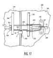
- FIGS. 17-19show the cable being wrapped about the keeper bar-handle pivot bracket which prevents the keeper bar from being rotated sufficiently to open the door.
- FIGS. 17-19show a similar application of a cable seal to a cargo door keeper bar arrangement.
- the seals shown in the web site photosare mechanical seals such as that described in the aforementioned '447 U.S. patent.
- the stranded metal cable sealmay also be used to seal the hasps alone as depicted by the electronic security seal of the present invention in FIG. 18 herein and generally depicted in FIG. 17 herein (and which also is shown wrapped about the keeper bars).
- the problem with this arrangementis that the electronic seal disclosed in U.S. Pat. No. '973 noted above is disclosed only as useful with a steel bolt. It can not be used with a stranded metal cable.
- This sealrequires an electrical conductor to pass through the cable so that when the cable is severed, the electrical conductor is also severed presenting a tampered state. See for example the patent to Pate discussed above.
- the present inventionrelates to an electromechanical cable seal data recording/playback apparatus with its control method; and, also to a radio transponder apparatus with its control method, a description of the prior art relating to the present invention relates to a number of different structures, a mechanical seal, a tamper detection and monitoring circuit and a transponder circuit for receiving and transmitting tamper conditions as described in the '973 patent and as employed in RFID circuits described therein.
- U.S. Pat. No. 6,265,973 to Brammall et al.discloses an electromechanical seal in which a fixed length bolt is locked to a seal housing, which is attached to the door handles of a cargo container.
- the electromechanical seal disclosed by the '973 patentonly seals the cargo container's handle to its door, but does not seal the door itself, i.e., the keeper bars.
- a typical cargo containerhas four steel keeper bars, which are vertically aligned, and comprising rotating bars that engage latches located at the ends of each keeper bar to lock the doors to the cargo container's frame. Only the handle of the right-hand cargo container door is usually sealed via hasps. The cargo container door's handle is fastened to the door.
- the present inventorsrecognize a need for an electromechanical security seal that will simultaneously seal the keeper bars of the doors and the handle which operates the keeper bars.
- the prior art seals discussed above using an electronic cable monitoring circuitare not disclosed as useful for operation with cargo container doors, especially containers that are transported aboard ocean going ships. In addition, they are insufficiently robust, leak moisture and use mechanisms and so on which are relative costly. They also do not deal with the problems encountered by seals used to seal containers shipped by sea. These containers may be secured over long periods of time such that the seals, which may be battery operated, lose voltage and thus may lose their ability to detect tampering. In addition, such containers are subjected to a wide variety of ambient conditions which also make monitoring the seals electronically more difficult. Shifts in electrical properties of the electrical conductor used with the cable being monitored may arise due to ambient atmosphere condition shifts thus causing errors in the detection of a tamper condition.
- An electronic tagging deviceis commercially available that is programmable and which transmits information that is programmed, such as tagging identification serial numbers and other information as desired. This is referred to as radio frequency identification (RFID) which is well known in the art.
- RFIDradio frequency identification
- an RFID tagwill have a radio frequency (RF) transmitter, an RF receiver, an RF modulator, and a memory.
- the memoryretains the digital code manifesting the identification number.
- the RF modulatorextracts the digital code representing the identification number as a modulated signal which is applied to the RF transmitter.
- the RF receiverreceives interrogation and control signals which manifest a request for the identification number.
- Such systemsprovide security tagging for high value merchandise as it is transferred from the manufacturer to the consumer.
- Other applicationsinclude tagging of animals, humans and vehicles such as trucks and their cargo containers.
- Other applicationsinclude automatic toll collection systems.
- FIG. 11illustrates a prior art RFID communication system 214 .
- the systemincludes an interrogator 216 and an RFID tag 218 .
- the interrogator 216includes a host controller 220 to process received information from the RFID tag 218 via antenna 222 and receiver 224 .
- the host controller 220To retrieve information from the RFID tag 218 , the host controller 220 generates an interrogation command signal which is transmitted by transmitter 226 and antenna 228 as signal 230 .
- the tag 218transmits RFID signal 232 via antenna 234 in response to receipt of the interrogation command signal 230 .
- the receiver 224receives the signal 232 via antenna 222 .
- the signal 232manifests the identification number of the tag 218 .
- the RFID tag 218has an antenna 236 and a receiver 238 to receive the interrogation command signal 230 from the interrogator 216 .
- the receiver 238transfers the received command signal to a controller 240 .
- the controller 240interprets the command and extracts the corresponding identification number (ID) from memory 242 .
- the extracted identification numberis then transferred by the controller 240 to transmitter 244 which transmits the ID to antenna 234 which broadcasts the signal 232 .
- the controller 240may have an interface, not shown, to receive data from external transponders such as temperature sensors, pressure sensors, global positioning sensing and other data including telemetric measurement data.
- the RFID tagsmay simultaneously respond.
- the responsesmay collide and the identification codes may be garbled and lost.
- the interrogatorwill rebroadcast commands to establish an order of broadcast of the RFID tags. This ordering of the broadcast is possible only from active RFID tags.
- U.S. Pat. No. 5,479,160 to Koelleprovides an inexpensive circuit that consumes low power, can detect low level RF signal and RF signals of varying strength, and can reject intermittent low level RF interference.
- Logic circuitryis provided to insure that the read/write circuitry of the tag will not be activated unless the polarity of the reactivation signal is detected for a specified time.
- U.S. Pat. No. 5,541,604 to Meierallows the use of a single set of circuitry in each of the interrogator and the transponder for transmission and reception of both powering and communication signals; without the need for synchronization between interrogators.
- PWMpulse width modulation
- PPMpulse position modulation
- FSKfrequency shift keying
- U.S. Pat. No. 5,485,154 to Brooks et al.encompasses systems and methods of communicating with or identifying more than one remote device employing random sequence selection of a carrier signal frequency from a defined set of carrier frequencies.
- the remote deviceselects a carrier signal frequency and transmits data such as an identification code using that frequency and then reselects the same or a new carrier signal frequency for the next transmission event.
- U.S. Pat. No. 6,420,971('971) to Leck et al. discloses an electronic seal including a padlock type housing and a closure member such as a shackle to form a seal.
- the closure memberhas an outer portion surrounding a core.
- a sensor assemblysenses the integrity of the core such that tampering with the seal can be detected.
- the coreis a fiber optic cable with an integrity sensor comprising an optical source and an optical detector. The optical cable can be bypassed by knowledgeable individuals using optical connectors and a parallel optical cable.
- a padlock sealis not satisfactory for securing keeper bars of a cargo door.
- the system of the '971 patentuses a complex locking mechanism using a sacrificial latch or lock member to lock the ends of the cable to the lock body.
- the sacrificial membermust be destroyed or removed to open the lock. This is not satisfactory as the lock member may be reinserted to appear that no tampering occurred. It is recognized by the present inventors that the most secure lock is one which can not be returned to its original state visually as well as physically, i.e., the locking element must be permanently severed as the only way to remove the lock.
- a cablecomprising an outer steel sheath enclosing a central core comprising a wire for storing a charge and separated from each other by an insulating tube.
- the coreterminates just before the releasable end of the cable encapsulated therein and forming a capacitor the capacitance depending upon the cable length.
- the unitmeasures the capacitance of the cable periodically in one second intervals. A change in length of the cable changes its capacitance indicating tampering.
- a plurality of woven major strandswith two of the major strands comprising an outer sheath of woven minor steel wire strands enclosing a conducting central core separated by an insulating tube.
- Two of the major strandsare integrally connected at a releasable end to form a single loop strand extending from the fixed cable end to the releasable end and back to the fixed end.
- the remaining strandsare not used for signal transmission so that only two of the multiple strands, e.g., five, are used and are difficult for a tamperer to defeat as he will not know which strands are live.
- This systemis believed not viable for a cargo container system in that such containers may be tampered with out of view of others for a long period thus requiring a robust locking system wherein the seal can only be removed by cutting the cable, which is permanent damage to the system. Also, the cable may be bypassed with an identical cable (hot wired) which enables the primary cable to be defeated.
- U.S. Pat. No. 6,389,853 to Pate et al.discloses an apparatus and method for deterring theft of a computer.
- the apparatusincludes a lock having a housing and a retention member, such as an elongated member or tether cable.
- the retention memberhas a continuity detection element such as a wire having first and second conductors embedded therein and includes an outer cable portion made of metal stranded wire.
- the first and second conductorsare electrically isolated from one another by insulation which also electrically isolates at least one of the conductors from the cable portion.
- the conductorshave a first end at the anchoring end of the retention member electrically connected by a collar.
- the collarlocks the free end of the retention member to a portion of the retention member adjacent to the free end to form an anchoring loop.
- the retention memberis attached to the computer apparatus by a lock at a second end and terminates in the anchor portion, i.e., the loop, at the first end for anchoring the computer to an immovable object such as a desk or wall to deter unauthorized removal of the computer.
- the lockis unlocked by a key which engages a key mechanism.
- the retention membera cable with an electrical wire therein, is moved between a locked and an unlocked position by the key mechanism.
- a continuity detectordetects unauthorized detachment of the security apparatus from the computer or a break in the continuity of the wire in the retention member by periodically polling the retention member wire for continuity, i.e., an open condition or break in the retention member wire.
- the continuity detectorcompares a first reference voltage when the wire in the retention member is intact to a second reference voltage.
- the security deviceis removed from the computer or the wire is broken. i.e., presents an open circuit, in the retention member, the first voltage changes, activating an alarm, and/or notifying a system administrator and/or partially or fully disabling the computer system.
- a problem with this systemis that a stranded cable as disclosed therein may have the strands thereof pried apart to expose the inner conductor wire. A tamperer can then attach a hot wire across the retainer wire, i.e., by pass the retainer wire section with a parallel conductor wire. Then the retainer wire can be severed and the voltage there across will not manifest an open circuit.
- the cablecan be cut and the product removed, the wire reattached by soldering and the cable welded so that tampering would not be readily evident. This is not satisfactory. Also, not dealt with is the problem that when the detector is battery operated, and the battery voltage decreases over time, the tamper measuring circuit can create false tamper indications not due to tampering, but due to the battery drained state.
- a further problem with the above described arrangementis that it is complex and uniquely adapted for releasing a product such as a computer with a key.
- the tether cableis required to be formed into a loop for attachment to a desk or wall.
- the looprequires a collar which receives two free ends of conductors which are electrically connected by a connector embedded in the collar, which adds cost and which is also subject to tampering.
- the free end of the conductorsmay be pulled free of the collar without affecting the integrity of the conductor continuity by hot wiring as noted above and immediately reconnecting the freed ends of the conductor. This is not satisfactory for a cargo container door seal.
- the freed endsmay be reattached in a period intermediate the polling of the voltage across the conductor, the intermediate polling period not being specified or being directed to this problem. This will defeat the seal by opening the loop and free the computer. Then the conductor's free ends can be reinserted into the collar so that evidence of tampering is not visually or electrically evident. Also the key lock is subject to tampering and adds cost unnecessary to a cargo container lock system. What is needed for cargo containers is a security seal that is simple, robust and low cost and once defeated can not be returned to a state where it is electrically and visually the same as if not defeated. Also needed is a seal that is adapted to deal with battery and environmental conditions that shift over time.
- U.S. Pat. No. 5,298,884 to Gilmore et al.discloses a wearable tag with an electronic house arrest monitoring system (EHAM) which is held to a limb of the wearer by a lockable strap.
- the tagincludes tamper detection circuitry for detecting any attempt to remove the tag by cutting or breaking the strap, even when the cutting is in the presence of an electrolyte.
- the straphas a highly electrically conductive conductor embedded therein that is in electrical contact through known resistances to respective terminals on the tag.
- the tamper detectiondetects any change in resistance of the strap that might occur when the conductor is severed by interrupting the current to the resistances connected thereto. This requires additional circuit components, i.e., resistors that are also used to detect immersion in an electrolyte by using dissimilar metals in the circuit.
- the circuitsperform two functions: 1) to transmit a unique identification signal that is processed by one or more receivers allowing the location of the wearer to be monitored and 2) to sense the occurrence of a tamper event such as an attempt to remove the tag and signal the remote receiver of such an occurrence. It purportedly detects when the resistance increases by the addition of a jumper placed across the strap or when voltage changes when immersed in an electrolyte in an attempt to defeat the system. This implies that such a bypass jumper will by pass the resistor(s) as well to change the resistance. Therefore, these resistors are essential to proper operation and add cost to the device. However, if the cable is bypassed in a region intermediate to the resistors, no change in voltage may be observed.
- U.S. Pat. No. 6,297,735 to Abeldiscloses a lock for locking valve and electrical switch handles in an off position and incorporates a radio transmitter for reporting the status of the lock to a remote monitor.
- the lockhas a cable which encircles the handle. One end of the cable is connected to the lock and locked in place. A conductor of an alarm subcircuit passes through the cable for detecting whether the cable has been cut.
- the monitorincludes a radio receiver and a display for displaying the status of the lock using an RF transmitter in the device circuit.
- U.S. Pat. No. 6,727,817 to Maloneydiscloses a tamper detection and prevention for an object control and tracking system, in particular, a key tracking system, and more particularly, a padlock type seal not useful for securing cargo door keeper bars.
- a key cardis attached to a key having a touch memory device, RFID tag, or other circuitry for storing and transmitting an ID to a controller.
- a keyis attached to the card by a conductive tether and transmission of the ID code passes through the tether. If the tether is cut, transmission is interrupted and indicates tampering.
- the tetheris resistive, and circuitry monitors the voltage drop across the tether.
- An object of this patentis to detect removal of the key from its ID card while the card is left intact.
- This referencedoes not suggest its system is useful with cargo containers and the like.
- a change in voltageindicates tampering.
- cargo containers aboard shipsare subject to a wide variety of ambient weather conditions wherein the temperatures may vary significantly, for example, through out the world exhibiting extreme cold and hot temperatures variations. Since it is important to know when a fault occurred in the seal cable, this parameter needs to be accurate at all times. Also, if battery operated, shifting voltage values of the battery are not considered.
- An electronic security sealincludes a housing having a cavity; a cable locking device in the cavity; a cable having a hollow core and a first sealed free end and a second end, the second end being secured fixedly secured in the cavity, the first free end for selective insertion into engagement with the received locking device to lock the free end in the cavity.
- An electrical conductoris in the cable hollow core, the conductor having a given resistance R, the conductor forming a loop within the cable and extending adjacent to the cable sealed first end, the loop terminating in a second free end with the conductor forming a pair of conductors extending beyond the cable at the cable second end and electrically connected to a first circuit.
- the first circuitis located in the housing cavity including a signal generating circuit for generating a first signal manifesting a first cable locked state indicating that the cable free end is locked, the first circuit being responsive to a sensed tamper condition of the conductor for generating a second signal manifesting the sensed tampered condition of the locked cable.
- a resistance measuring circuitperiodically measures the resistance value of the electrical conductor loop, the first circuit being responsive to the measuring circuit for generating the second signal when the resistance value of the conductor loop differs from a predetermined reference value to provide a sensed tamper condition.
- the first circuitincludes a power source having an output voltage that decreases in value during a time period, the first circuit being arranged to correlate a reference resistance value for the conductor to a measured ambient temperature value and to a measured decreasing power source output voltage value.
- the power sourceis a battery.
- the first circuit power source output voltagedecreases in value during an elapsed time period and the first circuit includes a stored table in memory of reference power source output voltage values each corresponding to a reference resistance value, the circuit for measuring the power source output voltage value and for comparing the measured output voltage value with the stored reference voltage values to obtain a reference resistance value corresponding to the measured output voltage and for comparing the measured resistance value of the conductor to the obtained reference resistance value.
- the first circuitincludes an ambient temperature sensor and a stored table of reference temperature values each corresponding to a reference resistance value, the circuit for periodically determining the ambient temperature and for comparing the determined ambient temperature value with the stored reference temperature values to obtain a reference resistance value and for comparing the measured resistance value of the conductor to the obtained reference resistance value.
- the first circuitincludes a power source and a stored table of reference resistance values each correlated to a given power source output voltage and ambient temperature, the first circuit for measuring the power source output voltage, the ambient temperature and the conductor resistance and for comparing the measured voltage and ambient temperature to the table voltage and temperature values to obtain a reference resistance value, the first circuit for comparing the measured resistance value to the reference resistance value.
- the first circuitis responsive to a command signal, the first circuit including a memory for storage of time/date data and being arranged for periodically transmitting the time/date and tampered status of the cable during that period upon receipt of the command signal.
- the first circuitincludes an alarm circuit for generating and transmitting an alarm signal including a data signal manifesting the time/date stamp of the alarm signal upon detection of a tamper condition of the cable manifested by the measured resistance value of the conductor.
- the sealincludes an electrical contact arranged to engage the received locked cable free end for arming the first circuit to commence periodically polling and recording the locked status of the cable and associated time/date of the recording.
- the sealincludes an arming arrangement responsive to a received arm command signal for arming the first circuit and commencing monitoring the locked cable tamper free status.
- the circuitincludes a shut down arrangement for shutting down the first circuit at the end of a predetermined period after the arming of the first circuit.
- the housingincludes a first compartment for receiving the cable and a second compartment containing the first circuit, the first and second compartments being hermetically sealed from each other in the cavity, the second compartment being hermetically sealed from the ambient atmosphere.
- first and second compartmentshave a common wall, the conductor exiting the cable in the first compartment and passing into the second compartment through the common wall and sealed to the common wall with a hermetic seal.
- the locking deviceincludes an extension, the extension for receiving the cable second end, and a cable securing arrangement for fixedly securing the cable second end to the extension.
- the sealis for securing the door or doors of a cargo container, the door or doors having keeper bars and a hasp, the cable having a length sufficient to secure the keeper bars and hasp.
- the first circuitis electrically connected to the conductor and responsive to the electrical conductivity value of the conductor, the first circuit including a signal generating circuit for sensing the conductivity value of the conductor and for generating a first signal manifesting a cable locked state indicating the cable is locked to locking device and tamper free when the conductor has a first conductivity value and for generating a second signal manifesting a cable tampered condition in response to sensing a change of conductivity of the conductor from the first conductivity value.
- a lidis included for covering the first compartment for sealing the first compartment from the second compartment.
- an RFID tagis associated with the first circuit, the tag for initializing the first circuit to an armed condition in response to a received arm command signal.
- the tagincludes a relay circuit for relaying electrical signals containing commands and data to and from adjacent seal tags forming a mesh network configuration.
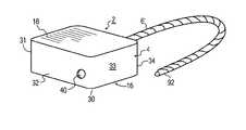
- FIG. 1is an isometric view of an electronic security seal according to an embodiment of the present invention with the cable free end ready for attachment to a hasp;
- FIG. 2is a top plan sectional view of the seal of FIG. 1 further including the cable in the locked state attached to a hasp;
- FIG. 2 ais an isometric sectional view of the housing of the seal of FIG. 2 without the components inserted;
- FIG. 2 bis a top plan sectional view of the seal of FIG. 1 further including the cable in the locked state attached to a hasp according to a second embodiment;
- FIG. 3is a side elevation partially in section view of the seal of FIG. 1 with the cable inserted and locked in place;
- FIG. 4is an exploded view of the seal of FIG. 1 ;
- FIG. 5is a side sectional elevation view of the locking device of the seal of FIG. 1 ;
- FIG. 5 ais a side sectional elevation view of the locking device of the seal of the embodiment of FIG. 3 ;
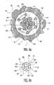
- FIG. 6is a side elevation view of the locking member of the locking device of FIGS. 5 and 5 a;
- FIG. 6 ais a cross section elevation view through the locking member of FIG. 5A .
- FIG. 6 bis an end elevation view of a locking member of FIG. 6 .
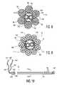
- FIG. 7is a plan view partially in section of the cable showing the conductors inside the cable core employed in the embodiment of FIG. 1 ;
- FIG. 7 ais a more detailed fragmented sectional view of a portion of the cable of FIG. 7 showing the tube and conductors inside of the tube;
- FIG. 8is an end sectional view of the cable of FIG. 10 taken along lines 8 - 8 ;
- FIG. 9is an end sectional view of the cable of FIG. 7 according to a second embodiment taken along lines 9 - 9 ;
- FIG. 10is a plan view partially in section of the cable showing the conductors inside the cable core employed in a further embodiment
- FIG. 11is a block schematic diagram of a prior art RFID interrogation and tag system
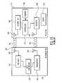
- FIG. 12is a schematic block diagram of an embodiment of a circuit for use with the seals according to the respective embodiments of FIGS. 2 and 2 b;
- FIG. 13is a diagram showing the functions of the seal controller and tag of FIG. 12 in more detail
- FIG. 14is a flow chart illustrating the steps performed by a seal according to an embodiment of the present invention.
- FIG. 15is a flow chart showing the resistance measuring portion of the circuit of FIG. 12 ;
- FIG. 16is a diagram showing the communication system of the seal according to the embodiment of the present invention.
- FIGS. 17-19are elevation fragmented views of a cargo container door showing various sealing arrangements of the keeper bars and handles of cargo containers with a seal according to the embodiment of FIG. 1 .
- electronic seal device 2includes a seal 4 and a stranded electromechanical metal cable 6 ′.
- the cable 6 ′is locked to the seal 4 and locks hasps 8 , 9 together.
- the hasps 8 , 9may be part of a cargo container (not shown), for example, for locking a container door 10 shut against a fixed part 12 of the container.
- the hasps and doorare schematic representations as their actual configuration may differ from that of FIG. 2 . See, for example, FIGS. 17-19 , wherein the hasps are used to secure a handle in place.
- the handleis rotatable for rotating an attached keeper bar, as explained in more detail later.
- the cablealso may have a length sufficient for wrapping about the keeper bars (See FIGS. 17 and 18 , for example) of the cargo container door 10 for retaining the door 10 locked in place.
- the cable 6 ′may have a length of several feet or more, for example.
- the hasps 8 , 9are secured respectively to the door 10 and the fixed part 12 of the cargo container.
- the cable 6 ′may also be wrapped about the door handle (not shown) or secured to the handle hasp (See FIGS. 17 and 19 ).
- the cable 6 ′is attached to a robust locking device 14 that is located inside of housing 16 of the seal 4 .
- the seal 4comprises a metal die cast housing 16 , preferably zinc, but may be other metals or molded plastic materials, such as thermoplastic, according to a given implementation.
- Attached to and enclosing the open top of the housing 16is a lid 18 of preferably transparent molded thermoplastic that hermetically seals the cavity 20 of the housing.
- the lid 18is attached by bonding, such as with an adhesive or by ultrasonic welding and the like.
- thermoplastic label support 22which may be a cut or molded sheet of relatively stiff preferably transparent material, and which may be opaque, is next adjacent to and beneath and visible through the lid 18 .
- the support 22is also bonded or welded in place and also may be opaque according to a given implementation for the reason to be explained below.
- a label 24is attached to the support facing the lid 18 and is visible through the transparent lid.
- Datamay be imprinted on the label or the data may be imprinted directly onto the support 22 substrate or onto the lid 18 in a known manner.
- the sheet material label 24may be plastic, metal or paper films.
- the data that is imprintedis preferably an ID number or code unique to each seal such as a serial number (not shown).
- the ID datamay be in the form of a bar code and preferably is a unique number assigned to each seal.
- the dataalso preferably may include the name of the seal manufacturer.
- a printed circuit board assembly 26is beneath the optional label support 22 .
- the circuit board assembly 26carries the circuit elements which implement the circuit of FIGS. 12 and 13 . This circuit performs the steps of FIGS. 14 and 15A and 15 B.
- Beneath the circuit board assembly 26is a lid 27 , which may be thermoplastic.
- the lid 27covers the locking device 14 , which is beneath the lid 27 and which rests in a compartment 48 ( FIG. 2 a ) between the bottom wall 30 ( FIG. 2 a ) of the housing 16 and the lid 27 .
- contact assembly 28shown in phantom
- FIGS. 2 b and 5 ais optionally adjacent to the locking device 14 .
- the housing 16is shown in more detail and includes bottom wall 30 and four side walls 31 - 34 extending from the bottom wall, the walls defining cavity 20 .
- a pair of cable receiving apertures 36 , 38are in side wall 34 and a cable receiving aperture 40 is in side wall 32 aligned with aperture 36 on axis 46 .
- Two parallel inner walls 42 , 44normal to and extending from side wall 33 , extend upwardly from bottom wall 30 .
- Wall 42is L-shaped with an L-portion 42 ′.
- Walls 42 , 44each have a respective cable receiving aperture 42 ′, 44 ′ and which are aligned with apertures 36 and 40 on axis 46 .
- Walls 42 and 44 , side wall 33 and bottom wall 30define a first compartment 48 in cavity 20 for receiving the locking device 14 .
- Walls 44 and a portion of walls 34 and 33 and bottom wall 30define a second compartment 50 in cavity 20 .
- a portion of wall 32 and wall 42 , a portion of side wall 33 and bottom wall 30define a third compartment 52 , which receives the optional contact assembly 28 ( FIG. 5 a ).
- Wall 54 , a portion of bottom wall 30 and the side walls 32 , 34define a further compartment 48 ′ between compartments 48 , 50 and 52 and wall 54 .
- Compartment 48 ′is an extension of and in communication with compartments 48 , 50 and 52 for receiving the locking device 14 and a portion of the cable 6 ′, FIG. 2 .
- Wall 54 in cavity 20extends partially upwardly from the bottom wall 30 the same extent as walls 42 and 44 and divides cavity 20 into a further compartment 56 . All of the walls and the housing 16 are preferably molded one piece die cast zinc.
- the upper surfaces of walls 54 , 42 and 44form a continuous ledge. This ledge is coplanar with and continuous with U-shaped shoulder 60 which extends inwardly into cavity 20 from side walls 32 , 33 and 34 .
- the walls 54 , 42 , and 44 and shoulder 60form a support surface for lid 27 ( FIG. 4 ), FIG. 3 .
- Lid 27which may be thermoplastic sheet material, is bonded to the upper surfaces of walls 42 , 44 and 54 and shoulder 60 to form a hermetic seal therewith over compartments 48 , 50 and 52 . Thus any moisture that enters these latter compartments via apertures 36 , 38 or 40 is precluded from entering the compartment 56 , FIGS. 2 and 2 a .
- This sealing of compartment 56 via the lid 27 and lid 18 on shoulder 60 and wall 54 , FIG. 4ensures no moisture or other contaminants are deposited on the printed circuit board assembly 26 . Such moisture and contaminants will enter the compartments 48 , 50 and 52 via the apertures 36 , 38 and 40 , FIG. 2 a , which apertures are not sealed, with or without the cable 6 ′ inserted therein, FIG. 2 .
- the lid 27 , FIG. 4has an aperture 128 for receiving wire leads 126 from the cable 6 ′. These leads are hermetically sealed to the lead by any suitable potting material and the like.
- the circuit board assembly 26is located in the hermetically sealed portion of the cavity 20 and is protected from ambient atmosphere contaminants such as moisture and so on.
- Representative wall 31has in common with all of the upstanding walls 32 - 34 a continuous lower inwardly facing shoulder 58 on which the circuit board assembly 26 rests.
- the assembly 26is attached to the shoulder 58 , for example, by fasteners (not shown), by bonding, e.g., adhesive or ultrasonic welding, and so on.
- the shoulder 58extends about the cavity 20 and defines a plane above the walls 42 , 44 and 54 relative to the bottom wall 30 above the lid 27 , FIG. 4 .
- a second shoulder 62Spaced above shoulder 58 , FIG. 2 a , is a second shoulder 62 , which like shoulder 60 , extends completely around the cavity 20 on all of the walls 31 - 34 .
- Shoulder 62receives and supports the label support 22 , FIGS. 3 and 4 .
- a third shoulder 64similarly extends completely around the cavity 20 adjacent to the top upper surfaces of walls 31 - 34 , FIG. 2 a .
- Shoulder 64receives and supports the lid 18 , FIGS. 3 and 4 .
- the lidis sealed to the shoulder 64 by adhesive, bonding or ultrasonic welding forming a hermetic seal therewith.
- cavity 20 compartment 56is hermetically sealed from the ambient atmosphere by walls 30 , 31 - 34 , 54 and lids 18 and 27 .
- locking device 14comprises a robust steel or iron, machined or cast, body 66 having a longitudinally extending cylindrical bore 68 which closely receives the cable 6 ′.
- the bore 68terminates in a tapered bore 70 .
- the bore 70tapers from a small diameter defined by bore 68 to an enlarged diameter at the opposite end of the bore 70 at end wall 72 of the body 66 .
- Wall 72is swaged over to enclose the tapered bore 70 .
- Member 74Located within the bore 70 is a locking member 74 .
- Member 74comprises a length of wire, preferably steel, more preferably stainless steel, circular cylindrical, which is formed into a serpentine shape, FIG. 6 .
- the body 66 and locking member 74are similar to or identical to a locking body and locking member shown and described in detail in U.S. Pat. No. 5,582,447 mentioned in the introductory portion. Reference is made to this patent for a more complete description of these elements, which patent is incorporated by reference in its entirety herein.
- the locking member 74is described in that patent as a clip and whose structure is preferably identical as the clip.
- the locking member 74is hexagonal, FIGS. 6 a , and 6 b , or circular (not shown) in end view.
- the member 74comprises a metal wire, preferably circular cylindrical, bent into the serpentine shape as shown in FIG. 6 .
- the member 74includes three U-shaped loop members 260 , 280 and 300 forming radial resilient axially extending fingers along axis 76 .
- Members 260 and 280are preferably identical.
- Member 260has at one end a circular segment base portion 320 .
- Two preferably linear legs 340 , 340 ′extend from the base portion 320 .
- the legscould also be arcuate in the form of lobes.
- Member 280has a circular segment base portion 360 at one end from which two preferably linear legs 380 , 380 ′ extend. The opposite ends of the legs 340 and 380 are interconnected with a circular segment end portion 400 .
- Loop member 300has substantially the same dimensions and shape as loop members 260 and 280 .
- Member 300comprises a circular segment end base portion 420 and a pair of linearly extending legs 440 and 440 ′.
- Leg 440 ′is segmented into two end sections 460 and 460 ′of the ends of wire 520 . These sections while spaced essentially form a leg of the member 300 .
- the sections 460 and 460 ′function and cooperate generally as if integral as the one piece legs of he other members 260 and 280 .
- Section 460is connected to the leg 340 ′ by circular segment end portion 480 .
- Circular segment end portion 500connects the legs 341 and 440 . All of the legs except legs 440 ′, the base portions and end portions are substantially identical.
- the members 260 , 280 and 300are each planar as are the end portions 400 , 480 and 500 so as to form a hexagon in end view.
- the locking member 74is substantially symmetrical. Symmetry is desired because the locking member can then be inserted into the body 66 bore 70 regardless the member 74 orientation. However, asymmetrical locking members can also be used and these must be inserted into the bore 70 in one relative orientation.
- the pitch d of the loop members, FIG. 6 ais important.
- the pitchis the spacing between adjacent loop members.
- the pitchis preferably about 1.5 times the diameter of the wire forming the member, which wire is circular cylindrical in this embodiment.
- the drawingis not to scale. The further apart the loop members for a given wire diameter forming the locking member, the less effective the resilient gripping of the cable 6 1 .
- the locking member 74is radially compressed against the cable 61 inserted into its central open region bore 78 along the entire length of the locking members along its legs and axis 76 . This provides the locking member with enhanced gripping action to the engaged surfaces of the cable 6 1 .
- the radial resilienceaccommodates a wide range of tolerances and dimensional variations of the cable being secured thereto.
- the locking membermay also be circular in end view. Reference is made to the aforementioned '447 patent for further description of the locking member, various embodiments thereof and the mating lock body configurations which may be used with a given locking member and incorporated by reference herein. Such other embodiments may be used according to a given implementation of the seal herein.
- the locking member 74has an internal transverse dimension t, FIG. 6 b , that is smaller than the smallest expected cable 6 , 6 ′, or 6 1 outer diameter in the tolerance range for that cable.
- a 1 ⁇ 4 (0.250 inch or 6.4 mm) inch diameter cablemay have a nominal tolerance of +/ ⁇ 0.020 inches (0.5 mm) or a minimum diameter of 0.230 inches (5.9 mm).
- the member nominal internal diameter tis smaller than this smaller value. This ensures that the member 74 always resiliently grips the cable regardless its tolerances in diameter, when inserted in the member 74 bore 78 , FIG. 6 b , along member 74 axis 76 .
- the locking member 74is first inserted in the bore 70 of the lock body 66 in either of two opposite axial orientations of the locking member due to the symmetry of the locking member 74 . Once inserted, the end wall 72 is swaged closed as shown to secure the locking member inside of the bore 70 .
- locking member 74is described in a preferred embodiment, it should be understood that any available locking device for securing a stranded cable to the seal housing may by used in the alternative.
- the locking device 14includes a laterally extending extension 80 which has a bore 82 .
- the bore 82closely receives end 84 of the cable 6 ′.
- the cables 6 ′ of FIGS. 5 and 6 1 of FIG. 6 adiffer somewhat from cable 6 ′ as explained below in more detail, but their operating principles with respect to the locking member 74 is the same. The different cables are shown for purposes of illustration.
- the cable 6 ′is preferred for reasons to be explained.
- the extension 80is received in compartment 48 ′, FIG. 2 b .
- the cable end 84is staked to extension 80 by permanently deforming a portion of extension 80 with a depression 86 , e.g., FIG. 2 .
- the cable 6 ′is inserted into the seal 2 in insertion direction 88 , FIG. 2 .
- the cable 6is passed through the apertures 36 , 44 ′, 42 ′ and 40 exiting the compartment 52 and the wall 32 as shown in FIG. 2 .
- the cable 6 ′may extend beyond the seal housing for any desired length and forms a loop portion 90 of any desired length as the loop portion is tightened about the hasps and/or keeper bars as shown in FIGS. 17-19 .
- the locking deviceprevents the inserted cable 6 ′ from displacing in the opposite direction maintaining the desired tautness in the loop portion.
- the locking membergrips the cable 6 ′ as it is passed through the lock bore 70 in direction 88 .
- This grippingpulls the locking member 74 in direction 88 toward the tapered larger diameter of the bore 70 .
- the locking memberbeing radially resilient expands sufficiently in the enlarged bore portion by the pushing action of the cable through the locking member 74 bore 70 , to permit the cable to be pushed through the locking member bore 78 , FIG. 6 a .
- the cableis pushed through an amount so that the loop portion 90 , FIG. 2 , of the cable is as taut as desired with respect to the hasps 8 and 9 , keeper bars or other elements about which the cable may be wrapped.
- the cablecan not be withdrawn in a direction opposite to direction 88 . This is because the locking member always is gripping the cable even when displaced toward and against wall 72 , FIG. 5 .
- the gripped cablewhen pulled in the withdrawal direction opposite to direction 88 pulls the locking member 74 therewith and wedges the locking member against the smaller diameter bore 70 of the lock body 66 . This resiliently crushes the locking member radially inwardly against the cable locking the cable to the locking device 14 .
- the more force applied to the cable in the withdrawal directionthe greater the wedging force and thus greater the forces locking the cable to the lock body 66 .
- the cable free end 92is inserted in locking engagement with the locking member 74 , the cable end 92 can not be withdrawn from the seal 2 without permanently destroying the seal or cable.
- Cable 6comprises galvanized steel strands 94 which are wrapped to form a twisted bundle 96 of strands 94 .
- the cable 6comprises six bundles 96 of such twisted strands 94 .
- the bundles 96are wrapped about a central tube 98 having a hollow core 100 .
- the tube 98may be of any electrically insulating material such as thermoplastic or other materials.
- the materialmay also be aluminized mylar sheet material, i.e., an aluminum coating, if necessary, to provide electrical shielding of the wire 104 conductor from stray external electrical fields and the like.
- the cable 6 strands 94may be of any gauge.
- the cable bundle 96there are 19 strands to a bundle 96 wherein the cable bundle 96 may be referred to as a 6 ⁇ 19 bundle, 19 strands per bundle and 6 bundles per cable. All of the bundles 96 are preferably identical, but may differ from one another if desired.
- the wires 104may be 26 AWG copper strands in this embodiment, but can be other gauges according to a given implementation.
- the wires 104are encased in optional insulation 106 which may be plastic, e.g., solid or foam, and are used to support the tube 116 as the cable is wrapped about the tube 116 .
- the core 100may be filled with an insulating filler material 108 .
- the wire 104may be a single loop and is commercially available. It may be stranded or solid. If solid it may be extruded.
- cable 6 ′which is preferable for use in the disclosed seal of the present embodiment, comprises nine bundles 112 of seven strands 110 of 26 gauge galvanized steel wire 97 , which bundles form a hollow core 114 .
- a thermoplastic tube 116preferably PVC, is located in the core 114 .
- the wires 104may be 26 AWG copper strands in this embodiment, but could be other gauges or solid as discussed above according to a given implementation.
- the wires 104are encased in insulation 106 .
- the core 100may be filled with an insulating filler material 108 as discussed above for the embodiment of FIG. 8 .
- the cables 6 and 6 ′may be about 1.5 meters or any other length as suitable for a given need as discussed below in connection with FIGS. 17-19 .
- cable 6 ′has one end 118 that is swaged, fused or welded closed to seal the core 100 at that end.
- the wire pair 102comprising a single wire 104 terminates in a loop 122 about 2.5 cm or less from the tip of the end 118 .
- the loopin the alternative may be formed by a splice at one end of two parallel wires 104 .
- the wire pair 102is thus formed as a loop of a single or spliced wire 104 conductor having opposite exposed adjacent bared wire ends 122 .
- the wire pair 102exits the cable core 100 adjacent to, but spaced from, the opposite second end 120 of the cable in an opening 124 in the side of cable 6 ′.
- the leads 126 of the wire pair 102 exiting the opening 124may be several centimeters, e.g., 5-7 centimeters, long according to a given implementation.
- the wire bared ends 122are attached to the circuit 138 of circuit board assembly 26 , FIGS. 3 and 4 .
- the wire leads 126exit the cable 6 ′ in the compartment 48 ′ and are electrically connected to the circuit 138 on circuit board assembly 126 in compartment 56 .
- the leadspass through aperture 128 in lid 27 into compartment 56 ( FIGS. 2 a and 3 ).
- the leads 126are then sealed to the lid 128 by a suitable epoxy or potting material as described previously.
- This potting materialhermetically seals the compartment 56 ( FIG. 2 a ) containing the circuit board assembly 126 . This seal prevents moisture and other contaminants that might be present in the ambient atmosphere from attacking the circuit board assembly 26 via the cable apertures 36 , 40 ( FIG. 2 a ) and compartment 48 in the seal housing 16 as noted above.
- compartments 48 , 48 ′, 50 , and 52 of the housing receiving the cable 6 , 6 ′ or 6 ′′is open to the ambient atmosphere and thus is subject to moisture contamination as discussed herein.
- the bared ends 122 of the wires of leads 126are soldered or otherwise connected to the circuit of circuit board assembly 26 in compartment 56 ( FIGS. 2 a and 3 ).
- the location of the leads 126 relative to the extension 80 , FIGS. 2 and 5 ,is important.
- the leads 126exit the cable 6 ′ prior to the entrance of the cable 6 ′ in the extension 80 , FIGS. 2 b and 5 .
- the leads 126are not deformed or damaged by the staked depression 86 , FIG. 2 , in the extension 80 , which depression may deform the cable 6 ′.
- the resistance of the wire 104is not changed after the staking operation of the cable 6 ′ to the extension 80 .
- Thisis important as it may be desirable to measure the resistance of the wire 104 to calibrate it to voltage and temperature variations as described hereinafter prior to installation of the cable 6 ′ to the seal extension 80 .
- cable 6 ′′is also a preferred embodiment.
- cable 6 ′′according to a second embodiment has one end 118 ′ that is swaged, fused or welded closed to seal the core 100 ′ at that end.
- the wire pair 102 ′terminates in a loop 122 ′ about 2.5 cm or less from the tip of the end 118 ′.
- the wire pair 102 ′is thus formed as a loop of a single wire 104 ′ conductor having opposite exposed adjacent bared wire ends 122 ′.
- the wire pair 102 ′exits the core 100 ′ at the opposite second end 120 ′ of the cable in an opening 124 ′ in the end of cable 6 ′′.
- the leads 126 of the wire pair 102may be several centimeters, e.g., 5-7 centimeters, long according to the implementation.
- the wire bared ends 122are attached to the circuit of circuit board assembly 26 , FIGS. 3 and 4 .
- the wire leads 126exit the cable 6 in the compartment 48 ′. This location prevents damaging the wire leads by the stake depression 86 in the extension 80 .
- the leads 126pass through aperture 128 in lid 27 .
- the leads 126are then sealed to the lid 128 by a suitable epoxy or potting material. This material hermetically seals the compartment 56 ( FIG. 2 a ) containing the circuit board assembly 126 .
- the bared ends 122 of the wires of leads 126are then soldered or otherwise connected to the circuit of circuit board assembly 26 in compartment 56 ( FIGS. 2 a and 3 ).
- the cable 6 1may be formed of the same gauge wires as discussed above for the embodiments of FIGS. 7 and 10 , for example.
- the cable 6 1is formed of six bundles 130 of wire strands 132 with 7 strands per bundle.
- a thermoplastic tube 116 ′is inside the core 134 of the cable 6 1 .
- a wire pair 102is located inside the core and tube 116 ′. Otherwise the cable 6 1 is substantially the same as cable 6 ′, the outer diameters being determined for a given seal implementation and may differ among different embodiments of any of the cables or among the different cables.
- the circuit of printed circuit board assembly 26( FIG. 4 ) comprises a circuit board 136 with a programmable circuit 138 , shown in more detail in FIG. 12 , comprising a micro-controller CPU, controller 150 , as hereinafter referred to, i.e., a computer processing unit, one or more memories 152 .
- the circuit 138includes other circuit components 144 such as crystals, capacitors and resistors and conductors and so on for providing a programmable transmitting seal command control circuit and an RFID tag circuit 170 , FIG. 12 .
- the tag circuit 170includes its own controller 172 , FIG. 12 , which may be a micro controller.
- the term micro-controllerrefers to conventional integrated circuits, which form a control circuit.
- the latter tag circuitis somewhat similar to the circuit 218 of FIG. 11 . It may also be similar to the circuits described in certain of the patents noted in the introductory portion incorporated by reference herein and modified as described herein.
- the memory(s)may be volatile or read only.
- the memory(s)are preprogrammed into a memory chip and/or programmed by radio transmission into a programmable memory via its receiver.
- the data programmed into the memory 152may include some or all of the following: a seal identification code, i.e., a unique number (a serial number) assigned a particular seal, geographic location where the seal is being deployed, e.g., if a port, the port of origin of the container to which the seal is attached, container identification, e.g., a unique number assigned to a cargo container, the shipping carrier for the container, container destination, inventory of the container and other data.
- a seal identification codei.e., a unique number (a serial number) assigned a particular seal
- geographic location where the seal is being deployede.g., if a port, the port of origin of the container to which the seal is attached
- container identificatione.g., a unique number assigned to a cargo container
- the circuit 138is connected to the conductor terminal ends of the leads 126 , FIGS. 4 and 7 , to the cable 6 ′ wire pair 102 ( FIG. 7 ) which completes the circuit.
- a contact assembly 28may be included which comprises a connector element 144 , which includes either a metal or thermoplastic block, and is inserted in compartment 52 , FIG. 2 b .
- the assembly 28includes a resilient contact 146 , e.g., beryllium copper, connected to the circuit 138 by wire 148 for arming the circuit 138 by closing an ohmic connection to the circuit 138 arming circuit portion as depicted by the arm step 168 , FIG. 14 .
- the armed stateindicates that a cable is received and locked to the locking device 14 .
- the end 92FIG.
- the contact 146is J-shaped as shown, but may be S-shaped or any other shape with a resilient bent contact leg. The contact 146 only engages the cable outer surface during cable insertion after the cable 6 ′ is locked.
- the cable 6 ′does not engage a contact when inserted into the locking device 14 for locking engagement therewith.
- the circuit 138FIGS. 4 and 12 , is armed by remote transmission to the RFID tag 170 associated with the circuit 138 from the reader/interrogator 158 ( FIG. 12 ).
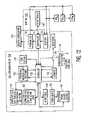
- FIG. 12illustrates in block diagram form the circuit 138 , FIG. 4 .
- the contact assembly 28( FIG. 5 a ) is shown in phantom in FIG. 12 as an alternative method to arm the circuit after the cable 6 ′ is locked to the locking device 14 .
- the circuit 138includes a seal command controller 150 which includes a CPU (central processing unit, i.e., a specialized computer).
- Controller 150which may be a 4 bit RISC MCU (microcontroller), may comprise any available programmable control circuit that is widely available.
- Controller 150is programmed to perform the functions described in connection with FIGS. 13-15A and 15 B.
- the programming circuitryincludes both volatile and non-volatile memory, such as memory 152 which may include both ROM and RAM.
- the controller 150receives transmissions via tag 170 controller 172 and the tag 170 receiver 154 .
- the tag 170may have similar circuits as RFID tag 218 , FIG. 11 .
- the tag 170transmits signals via its controller 172 and transmitter 156 .
- the transmitter 156transmits its radio signals to reader/interrogator circuit 158 such as circuit 216 , FIG. 11 , upon request from the circuit 158 or upon control of controller 150 .
- the circuit 216 in reader/interrogator circuit 158is modified by programmed instructions that perform according to the functions described herein below.
- the controller 150is programmed to include commands manifested by circuit modules 140 , 142 , 174 , 178 , 180 and 182 , FIG. 13 .
- Module 174periodically measures the resistance R of the tamper indicating wires 104 ( FIG. 7 ) inside the cable 6 ′ core (or any other cable used therewith) via resistance R measuring circuit 160 , FIG. 12 , of circuit 138 .
- This resistance Ris calibrated for the particular cable wire 104 length used for a given seal and preferably for temperature and voltage level of the power source 165 .
- Power source 165may be a 3 volt lithium ion battery optionally supplemented with a solar cell to provide auxiliary power via a trickle charge to the battery.
- the module 188includes a measure voltage control 140 for determining the power source voltage 167 ( FIG. 12 ) and a measure temperature control 142 for periodically measuring ambient temperature via sensor 176 ( FIGS. 4 and 12 ).
- Module 174determines the measured resistance R from circuit 160 , the measured voltage from circuit 167 and the temperature from sensor 176 ( FIG. 12 ). The module 174 then compares these values to a reference R value corresponding to the measured temperature and voltage values in a stored table (not shown) in memory 152 .
- the calibration of the resistance R of the cable sensor wireis provided by a table (not shown) stored in memory 152 , which may be a flash memory module as commercially available and commonly used in digital devices.
- This tablecomprises resistance values R, measured in micro-ohms (as the wires 104 , FIG. 7 , are excellent electrical conductors) calibrated for the given length of wire in the cable 6 ′ associated with the seal 4 ( FIG. 1 ) for real time measured ambient temperature and battery voltage (power source 165 , FIG. 12 ).
- the various different sealspreferably are provided with cables of standardized lengths associated with corresponding applications, such as for use with keeper bars alone, keeper bars and hasps together or hasps alone, as may be desired for a given implementation.
- the wires 104are standardized in gauge for the seals and thus in resistances R to provide predetermined resistances for each cable diameter and length, which may vary for different seals of different sizes intended for different end uses.
- a preferred wire 104is according to US Military Specification MIL-W-16878E (type ET) Hook Up Wire, TFE Teflon Insulation, either stranded or solid conductors, and is available in numerous gauges.
- seal command controller 150includes a command module 188 .
- the command module 188comprises a start module 178 , a measure module 174 , a format module 181 , a transmit module 180 , a voltage measuring circuit 140 and a temperature measuring circuit 142 .
- the start moduleinitiates the armed duty cycle command sequence and initiates the data signal format module 181 .
- the module 178also initiates the wire 104 R measure module 174 which controls the measuring of the wire resistance R by circuit 160 , FIG. 12 .
- the R valueis determined based on the stored table discussed above.
- the format module 178formats a data word signal from the measured R into an event log data word, e.g., date/time stamp, unique seal ID number, and condition of wire 104 , tamper or good, into RFID tag 170 memory (not shown in FIG. 12 ).
- an event log data worde.g., date/time stamp, unique seal ID number, and condition of wire 104 , tamper or good
- a shut down module 182may be included. This module issues a shut down command to the circuit 138 to shut down the circuit, step 218 , FIG. 14 , upon receipt of a shut down command (preferably including a password associated with the tag 170 ) from the interrogator 158 , FIG. 12 , or at the end of the predetermined X days of operation of the circuit, e.g., 70 days. This shut down, step 230 , FIG.
- shut downoccurs after the command module 188 via module 178 causes a data word log event (or trail of events recorded over the entire period the seal has been armed) to be transmitted to the reader/interrogator 158 from the tag 170 , step 214 , FIG. 14 , prior to shut down on receipt of a shut down command from the interrogator 158 .
- Shut downmay be initiated for example at any time prior to the 70 th day from start up by a program in module 178 , by receipt of an external command or automatically at the end of this period, if desired.
- the circuit 138may optionally be automatically shut down at the end of 1680 hours of active armed mode (70 days) by the program of module 182 , FIG. 13 , as may be desired for a given implementation. This shut down action occurs at this time provided no fault has occurred in the interim or no active shut down command is received from the interrogator 158 .
- the transmit module 180transmits the event log data word to the RFID tag memory (not shown in FIG. 12 ), which can be later downloaded (transmitted externally) upon receipt of a download command.
- the wires 104 , FIG. 7are tested to be sure they are in a predetermined resistance range at a given temperature, e.g., room temperature, within a desired preset temperature range such as +/ ⁇ 1° F. to +/ ⁇ n, for example, for each possible voltage range of the battery as the battery power, power source 165 , FIG. 12 , drains over time.
- the batteryhas a life of about 4-5 years and when operational at least about 70 days, which includes a safety factor in excess of the maximum expected time period in which cargo containers carrying the seals are in transit, e.g., up to about several weeks.
- the voltage level of the battery, power source 165 , FIG. 12is determined by programmed circuit 167 during a read resistance cycle initiated by controller 150 via module 160 , FIG. 12 and modules 140 and 174 , FIG. 13 .
- the temperature of the ambientis initiated by modules 142 and 174 , FIG. 13 and temperature sensor 176 , FIG. 12 .
- the cyclically measured voltage and temperatureare used to determine the R value of the wire 104 from the table of temperatures (T) and power source voltages (V) stored in memory 152 , FIG. 12 .
- the received electrical voltage signal from the wire 104is first converted from an analog to a digital format by an ADC (analog to digital converter) circuit (not shown) located in the cable signal monitoring module 160 .
- ADCanalog to digital converter
- the temperature of the ambientis measured by the temperature sensor 176 , FIG. 12 .
- the measured resistance R of the cable wire 104which forms a tamper evident sensor for the cables 6 or 6 ′, may vary with the actual voltage output of the battery source 165 , FIG. 12 , as well as in response to temperature shifts in ambient temperature sensed by sensor 176 and measured by module 142 , FIG. 13 .
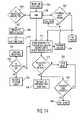
- the table of temperature T and voltage V values correlated to the R values of a good wire 104 stored in memory 152is referred to at the first R measurement of the wire 104 , step 149 , FIG. 15A , and then is periodically referred to after a number of hourly cycles has passed, step 151 , FIG. 15A .
- the period in which the table is consulted by the controller 150is preferably twice daily, or every 12 hours, or 12 hourly cycles, so as to verify that the measured R value corresponds to the corresponding acceptable R value in the table of T and V values.
- the initial R value of the wire 104is compared to the table in memory 152 at the initial R measurement step 192 , FIG. 15A .
- This stepfollows the initial action of insertion of the cable into the locking device 14 , FIG. 4 , at step 200 , FIG. 14 .
- the R valuesare measured on an hourly basis in the preferred embodiment. This cycle time however, may differ for different embodiments, and may be more or less frequent.
- the measured Ris good, i.e., R matches the referred to table value (or predetermined range of values) for the measured voltage and temperature at that time
- the value Ris saved in a memory location referred to in FIG. 15A as hold-area 1 , step 153 , which has a specific address in the memory 152 ( FIG. 12 ).
- the processreturns, after cycle count 1 , to the Start step 147 , FIG. 15A .
- the present measured Ris compared to the prior measured R value, step 155 , FIG. 13 .
- These R measuring cyclespreferably occur every hour to preserve power in source 165 , FIG. 12 , but may be at other cycle duration time periods according to a given implementation. These monitoring cycles are shown at step 202 , FIG. 14 .
- the measured R value of the wire of a cable 6 ′in digital format as converted by an analog to digital converter (ADC) (not shown) is compared to the previously measured R value at hold-area 1 at step 155 , FIG. 15A .
- a comparison of the present measured R valueis made to the previous measured R value in this and the following cycles up to cycle 12 (hour 12 after the start of the R measurement cycles).
- Each cycleis counted in step 151 and if not 1, 12, 24 or any multiple of 12, the present R is compared to the prior R measured value instead of referring to the table of T and V values.
- step 151the R value is compared to the stored table of V and T values for the measured V and T values of the present power source 165 state and the present ambient temperature as measured by sensor 176 , FIG. 12 . This confirms that the actual R value as measured each 12 hours is within the desired range for the present ambient conditions. If a fault is detected wherein the R measured does not match the table R (or range of values) for the measured T and V values, a fault signal will be generated at step 192 , FIG. 15A , and in FIG. 15B , this fault signal will result in a cable tampered fault entered into the signal event log memory at step 179 via steps 196 , 175 , and 179 , FIG. 15B .
- step 147The sequence of signal processing steps described in FIGS. 15A and B begins with an initial step 147 , followed by R value calibration step 192 , compare to table of T and V values for each 12 hours, step 153 when R is measured good, and then back to start step 147 .
- step 194exits to step 196 FIG. 15B , wherein it is confirmed that the fault is true at step 175 and then a fault signal is written into the log memory. If no fault is detected at step 192 , FIG. 15A , then the R value is saved in hold area 1 , step 153 .
- step 155follows step 151 wherein the present R is compared to the prior R and if acceptable at step 157 , R is saved at step 161 .
- the cable is good R value each 12 hoursis stored in memory and becomes an updated logged event at step 202 , FIG. 14 , which may be, if desired, transmitted at step 204 to a receiver (not shown) via the relay circuit 198 , FIG. 12 , or directly to a reader/interrogator 158 .
- the fault eventis transmitted automatically by the program of module 180 , FIG. 13 , of the command module 188 of the controller 150 (See also FIG. 12 ) to the RFID tag 170 .
- the tag controllercan be programmed to transmit the fault as a result of periodic polling of the tag 170 from the interrogator 158 or internally by the tag 170 controller, as may be desired for a given implementation.
- Module 186FIG.
- the tag 170downloads the received fault condition to the transmit event log module 190 of the tag which transmits this information to the reader/interrogator 158 upon interrogation from the interrogator 158 or, automatically as desired under control of controller 172 of the tag 170 , FIG. 12 .
- the controller 150is programmed to progressively monitor cable status signals during the armed period, i.e., transmitted signal R values of adjacent in time fault conditions.
- the controller 150may be programmed to optionally cause an additional R verification process to be performed by circuit 160 , FIG. 12 , at step 192 , FIG. 15A . This is to eliminate R measured anomalies caused by significant changes in environmental ambient conditions. That is, if at step 155 , a fault in R is measured by comparison to the prior measured R stored at hold area 1 , the system exits at step 159 to step 171 , FIG. 15B .
- Step 171proceeds to step 173 wherein the new R value is compared to the table of V and T values to confirm that the fault is real and not due to sudden extreme changes in ambient conditions or power source drop in voltage. If the fault is confirmed, then it is written in the memory at step 179 , FIG. 15B .
- the tag 170may also include a relay circuit 198 which under the control of tag controller 172 is part of a mesh network which is commercially available.
- the relay circuit 198relays the received fault condition immediately as detected from and to adjacent tag(s) with corresponding relay circuits of adjacent tag A , tag B and so on to tag N , which mesh network circuits are in wide use on RFID tags in commercially available systems such as from Savi or Intermec companies.
- the controller 172 of the RFID tagin this case is programmed to transmit the fault condition which is automatically received by the tag 170 as generated by the command module 188 .
- the adjacent tagsthen transmit the fault condition to other adjacent tags due to their short transmission range until a central interrogator/receiver at the host administrator 252 , FIG. 16 , receives the fault condition.
- a cable faultis first detected at the circuit 138 of the seal 4 .
- This eventis transmitted on to the next adjacent tag.
- This eventis relayed successively to next adjacent tags until the network administrator 252 receives the fault condition via the internet or other communication system 234 , FIG. 16 .
- the remote administrator 252can remotely arm a seal 4 circuit 138 via the same communications and mesh network 234 .
- a centralized administrator 2323may control multiple deployed cable seals.
- the RFID tag 170includes the RFID reader/interrogator 158 download command module 184 which is programmed to process the electronic signal that downloads the command from the reader/interrogator 158 ( FIG. 12 ).
- the programmed download command module 184initiates the download command controller module 186 which in turn initiates the command module 188 that executes the sequence described above.
- the transmit event log module 190is programmed to complete the download command for the circuit 138 initially generated by the reader/interrogator 158 .
- the RFID circuitoperates in a conventional manner and such RFID circuits are well known to those of ordinary skill and available from the Savi Corporation, for example, and others.
- the signal transmitting the fault conditiontransmits the fault condition, the unique tag serial no. eand container ID and time/date stamp to the central host unit at the network administrator 232 , FIG. 16 .
- Thisidentifies the seal with the cable fault so that the container with the seal fault can immediately be identified and located, if necessary, on board a ship, if the network administrator is located there, or at the next port if located there, as applicable, according to an embodiment of the present invention.
- the actual range of R values for a given temperature and a given voltageis determined empirically to correlate preset temperatures and battery voltages with a given resistance R value or range of values for that wire.
- the wire of each preset lengthis then exposed to different ambient temperatures, e.g., minus 40° to +200° F. at different preset voltages. This is done for example for those temperature ranges within the desired ambient range in which the resistance of the wire variation is minimal, e.g., 1 to 20° variations as may be determined for example and for each anticipated voltage value for each temperature.
- the resistance and voltagesare measured with commercially available devices.
- a table valueis created corresponding to the measured temperatures. This table is stored in memory 152 .
- the circuit 138measures the resistance via circuit 160 and voltage across the wire 126 , for example, FIG. 7 , via a voltage measuring circuit (not shown).
- the computer program in module 174 , FIG. 13then compares these measured values with that stored in the table of memory 152 to determine if there is a match.
- the circuit 138also includes an ambient temperature sensor 176 mounted on circuit board assembly 26 , FIG. 4 , which measures the ambient temperature in the vicinity of the seal.
- the controller 150seeks the matching temperature and battery voltage in the memory 152 table (not shown) corresponding to the measured battery voltage and sensed ambient temperature. It then compares the corresponding resistance value with the measured resistance value. If the measured resistance and stored values match within a predetermined range, the controller 150 formats a data signal in the programmed format module 178 , FIG. 13 , manifesting a non-tamper event. This data signal includes the time/date stamp of the measured resistance and the fact that the resistance was measured as “good” into an event data log which is stored in memory 152 ( FIG. 12 ). These logged events provide an audit trail of log events over the time the container is in a sealed condition.
- the resistance and the periodic measuring of the resistanceis programmed into the circuit 138 .
- the calibrated resistanceis used as a reference resistance variable against which the measured resistance of the cable 6 ′ is periodically compared by polling action of the controller 150 as programmed.
- the eventmay be recorded in memory as a log event, if desired, at step 202 , FIG. 14 .
- the controller 150is programmed to sense this state and generate an alarm.
- the alarm stateis downloaded (transmitted to memory or to the tag transmitter for external transmission as desired) with the alarm data and time/date stamp by circuit 162 under control of controller 150 , FIG. 12 .
- This actionoccurs at step 206 , FIG. 14 , which is “is armed state interrupted” which means a fault in the cable wire has been detected.
- This stateis broadcast at step 208 , FIG.
- the electronic signal information that is broadcastincludes the seal serial no. with the detected fault and the time/date stamp at which the fault is detected, step 210 , FIG. 14 .
- the tamper conditionis downloaded (transmitted) to the host system administrator 232 , FIG. 16 , identifying the tag and container as having a tampered condition, step 214 , FIG. 14 .
- the circuit 138may then be shut down at this time as a positive action, if desired at step 218 , FIG. 14 , by the transmission of a shut down signal from the interrogator 158 , FIG. 12 .
- This shut down signalis detected at step 218 wherein the shut down signal that deactivates the seal circuit would be received. If not received, the listen mode at step 220 remains on alert for such a deactivation signal. The listen step 220 waits for an interrogation signal from step 212 . If the seal circuit 138 shuts down for some reason which is an abnormal cycle, at step 222 , FIG. 14 , or a fault is detected in the cable, the optional red LED 139 , on the circuit board, FIG. 4 , will flash red, intermittently, to save power and an electronic signal containing the log data stored in memory 152 , FIG. 12 , is transmitted at step 204 . If no abnormal shut down, or no fault is detected, the green LED 137 will flash, preferably intermittently to save power.
- the various circuits of FIG. 12also represent programming instructions in the controller 150 for the different modes for example as shown in FIG. 13 .
- the controllermay be programmed to automatically shut down the seal's electronic components.
- this shut down of the seal's electronic componentsis optional as the seal may be allowed to operate until its battery runs down fully notwithstanding that the battery may be charged by a solar cell if desired.
- an electrical signal, an analog voltage, supplied to the cable 6 ′ wires 104 ( FIG. 7 ) from source 165has a voltage value of a certain value depending on the charge status of the battery represented by source 165 , in circuit 138 , FIG. 12 .
- the current for that voltagepasses through the copper wire loop core, wires 104 , FIG. 7 , and is received by the cable signal monitoring circuit 160 , FIG. 12 .
- steps 224 , 226 , FIG. 14representing the R measuring step. This measurement is under control of module 174 , FIG. 13 , of the command module 188 .
- the circuit 136optionally includes two LEDs 137 and 139 .
- LED 137is green and LED 139 is red. These LEDs illuminate depending upon the armed/alarm state of the circuit. When the circuit is armed, the green LED illuminates. It may illuminate steady or flash intermittently. The LEDs are visible externally through the transparent support 22 , transparent label 24 or window therein (not shown) if the label is opaque, and through the transparent seal housing lid 18 . When an alarm state occurs, the green light extinguishes and the red LED illuminates. In the alternative, the green LED may illuminate whenever the resistance of the wires 104 is polled and found acceptable. If polled and found unacceptable, the green LED if on, is shut off, and the red LED is illuminated, steady or flashes.
- the down load (transmission) of log dataoccurs in one instance during normal shut down of circuit 138 , which is initiated by the reader/interrogator 158 within the arbitrary 70 day period of operation of the circuit 138 .
- the circuit 138 power source 165 , FIG. 12 , battery (not shown),may be a button or other type of battery that has a shelf life of about 5 years.
- the resistancewill change in the wires 104 , 104 ′ of the cables 6 ′, 6 ′′, FIGS. 7 and 10 , respectively, from a closed circuit to an open circuit.
- the measured Rthus changes and represents a fault.
- a continuity testmay be used to detect faults. This open circuit condition is sensed by a circuit (not shown) and when the condition is passed onto the controller 150 , causes the controller 150 to generate an alarm state via circuit 162 , FIG. 12 and illuminate the red LED and extinguish the green LED, if present.
- the controller 150 programwill cause a download of the log data, circuit 162 , time and date stamp of the alarm indicating an alarm condition and, if desired, optionally all prior measured resistances with their time/date stamps upon interrogation by reader/interrogator 158 .
- the circuit 138 RFID tag 170may include elements of the circuit of FIG. 11 and further including the programmable EPROM or other programmable devices.
- Transmitter 156transmits an encoded signal intermittently at random time intervals, preferably hourly, when the wire 104 resistance is measured hourly, or at other intervals or as the R values are being measured, according to a given implementation.
- the circuit 138includes a programmable instruction set for programming a given ID (serial no.), and log data including time and date of resistance measurements manifesting a normal signal.
- circuit 138is armed, which may also in the alternative to the methods discussed herein be via an electrically insulated pull tag (not shown) or by the arming of the circuit via contact 146 engaging the cable 6 ′, FIG. 5 a , which is commonly used by others, connects the battery to the circuit 138 .
- the circuit 138begins transmission of the data on a periodic basis, previously programmed into the circuit, via transmitter 156 or in the alternative, selectively in response to interrogation.
- the reader/interrogator 158includes an antenna, a receiver/transmitter and a circuit (not shown) for decoding the received signal and converting it into the desired data for further transmission or display.
- the circuit 138is programmed by the program in the memory 152 to sense this condition at the next polling time via the resistance measuring circuit 160 . Even if the wire 104 were to be hot wired by a by pass wire, severed temporarily and then reconnected by soldering or by twisting the wires together, the R of the wire will change at the joined connection and be detected as a fault.
- the antenna(not shown) coupled to the receiver 154 and transmitter 156 , FIG. 12 , comprises a wound wire coil on a surface of the board 136 , FIG. 4 .
- the program of circuit 138in response to the periodic polling of the resistance R such as on the hourly basis, or in the alternative, upon interruption of power in another embodiment, or upon interruption of the circuit 138 , in a still further embodiment, by severing the cable, is programmed to transmit an electronic signal containing the downloaded data noted above, respective steps 204 and 212 , FIG. 14 .
- the reader/interrogator 158FIG. 12 , which may be hand held or permanently installed, adjacent to a conveyer of the cargo container or roadway for a trailer truck, transmits and receives the transmitted signal from the seal 4 .
- the term “sensor”is referring to the cable wire 104 which is used to sense the fault condition of the cable 6 ′.
- the reader/interrogator 158may be coupled to a local, but remote computer (not shown) or host network administrator 232 via a network 234 which may be the internet or other communications network such as a radio link and so on.
- the data signal from the reader/interrogator 158is forwarded to the computer (not shown) of the host system administrator 232 , FIG. 16 , via the communications network 234 .
- the system administrator 232may also indicate the detected fault state with a display (not shown) and may be programmed to set off an audible and/or visual alarm also or in the alternative. This alarm is immediate upon receipt of the detected fault and the transmitted signal immediately identifies the seal and the container that has been tampered with.
- the tamperingis noted at a given container location by reading the transmitted signal at a given different shipping and or receiving point at which the administrator 232 is located.
- the transmission of the signalsmay be at 900 MHz or 433 MHz protocols or other frequencies.
- the audit trail event log/linear data set generationmay be about 49 bytes total length.
- the cable wire (wire 104 , FIG. 7 ) and the associated fault detection circuitry and programmingis denoted generally as a cable lock sensor, e.g., sensor N 240 , which refers to the Nth cable seal 4 each corresponding to a separate one of N containers on a ship, for example.
- a cable lock sensore.g., sensor N 240
- the RFID tags 170 , FIG. 12include a relay circuit 198 which relays the data to adjacent tags A, B,-N.
- cable lock sensor A, 236detects a cable fault after being interrogated by interrogator 158 via sensors 240 - 238 , and relays the detected fault to next adjacent sensor 238 , which relays this information to next adjacent sensors and so on to sensor N, 240 .
- An instant alarmis transmitted from sensor to sensor.
- the interrogator 158interrogates sensor A via the N sensors
- the seal 4 , FIG. 1is assembled with the cable 6 ′ attached to the extension 80 , FIG. 2 .
- the cable 6 ′′ of FIG. 10may be attached to the extension 80 after the locking device 14 is assembled to the housing 16 , FIG. 4 .
- the cablemay be locked at both ends to the locking device which includes two locking members 14 but without the extension 80 .
- the difference in the cablesis where the wire pair exits the cable, before the cable end 120 in cable 6 ′, FIG. 7 and at the cable end 120 ′, FIG. 10 , and these termination locations are not necessary to or affect the seal function.
- the seal at this timemay or may not have an identifying serial number programmed into the circuit 138 .
- the unique serial number on the optional label, FIG. 4is visible through the lid 18 on the label 24 secured to the support 22 or, in the alternative, imprinted directly on the lid 18 without use of the label 24 and support 22 or imprinted directly on the support 22 without the use of a label 24 .
- a containeror door etc.
- This datainto its memory and a unique ID or number corresponding to the identification of the container and its contents, which may also be entered in the memory of the seal by remote programming transmission.
- the sealin the alternative is preprogrammed with the unique ID of the seal and with the data of the cargo container and the like including the container contents prior to being secured to the cargo container.
- the cable 6 ′is inserted fully into the seal locking device 14 until its free end is visible on the opposite side of the seal housing. This locks the cable to the locking device 14 locking member 74 .
- the cableis permanently locked to the locking mechanism and can not be removed without destroying the cable or seal 4 .
- the circuit 138once armed will periodically load its memory with the sealed stated of the cable as determined by the measured resistance of its sensor wire such as wire 104 , FIG. 7 , and will transmit the programmed seal identification and related data to a local interrogator/reader (not shown) upon interrogation or at other intervals as desired. This provides an audit trail of event data log representing an untampered seal.
- An alarm conditionwhen it occurs, is stored in memory 152 , and is transmitted when requested, or in the alternative, at the time of detection, e.g., at an hourly polling time.
- the alarm conditionis read by reader/interrogator 158 , the integrity of that container is assumed to have been breached.
- the reader/interrogator 158stores the seal number and time/date stamp of the occurrence of the fault detection of each seal that has been breached.
- a signal separation circuitFor example, a circuit as disclosed in the aforementioned copending application incorporated by reference herein may be used or other known circuits as described in the introductory portion may be used.
- any attempt to cut or sever the cablecauses an alarm signal to be generated at the time of polling of the resistance of the cable conductor.
- the alarm signalmay be repetitively transmitted. Thus it is important that no interruption of the circuit occurs once the circuit is armed.
- a tamperermay attempt to tamper the seal by spreading the individual wire strands apart to expose the internal wire 104 . Then a by pass wire, may be attached across a section of the wire 104 for example by twisting or a soldered connection. Then the by passed section of wire 104 is severed and the container or door opened. The tamperer then will attempt to simulate an untampered wire 104 by reconnecting the severed wire ends together and remove the by pass wire. Then the strands of the cable will be gathered together to appear as a single cable without being severed. It is necessary to detect this condition.
- the present inventioncontemplates this condition by measuring the resistance R of the wire 104 to small resistance values, e.g., micro-ohms. This will detect the presence of solder or twisted wire joints in the wire 104 and manifest a fault condition.
- the joint(s)present a change in resistance R values for the wire 104 and the circuit 138 module 160 , FIG. 12 , will detect this condition and indicate a fault. This is important as containers on a ship, truck, train or in a storage yard or any time in a port may be subject to long periods of isolation in which tamperers may have access to the seals 4 to commit such tampering.
- the circuit board assembly 26may include contacts on the printed circuit board for receiving the mating contacts of a programming unit for programming the circuit in one embodiment such as disclosed in the aforementioned commonly owned '973 patent.
- the circuitmay be preprogrammed with the serial no. and related data entered into the circuit by a received transmission signal.
- the copper wire loop circuit 138includes dual extruded copper wires, such as wires 104 , FIG. 7 , which may be spliced at the distal end of the cable assembly to create the loop.
- Another optionis a hollow plastic tube cable core such as tube 116 , FIG. 9 , which serves as a conduit to encase the copper wire loop of wires 104 .
- the cable/housing interfaceallows the two leads from the copper wire loop to exit the side of the cable at a point about 3.8 cm (11 ⁇ 2 inches) from the fixed end 84 of the cable assembly, FIG. 2 .
- the overall outside dimensions for the seal housingmay be: length about 7.5 cm (3 inches), width about 5 cm (2 inches) and height about 2.5 cm (1 inch).
- the sealcan be optionally armed when it is secured to the cargo container doors and keeper bars using an ‘arm device’ electrical circuit with the optional connector assembly 28 mechanical trigger or by transmission of an arm signal to the seal circuit.
- the seal 4 micro-controller 150is programmed to initiate a monitoring function for the inserted locked cable when either the ‘trigger’ circuit is closed or the arm signal is received.
- the seal 4 micro-controller 150is programmed to initiate a monitoring function for the inserted locked cable when either the ‘trigger’ circuit is closed or the arm signal is received.
- a (optional 70 day, more or less than 70 days in the alternative) monitoring audit trail event logis recorded by the controller 150 into the memory 152 .
- the controller 150is programmed, by a signal from module 186 of the tag 170 , in response to an interrogation signal from interrogator 158 , FIG. 12 , to shutdown the monitoring audit trail event log recording and transmit a signal to the active RFID tag 170 module 186 , FIG. 13 .
- This signalprompts the active RFID tag controller 172 , FIG. 12 , to go into log data download mode. This allows an authorized RFID reader/interrogator 158 to initiate a unique transmit audit trail event data log session with the active RFID tag component of the specified seal.
- An authorized interrogator/readeris one which uses the correct encrypted password to access a particular tag. Both the readers and the controller of the tags use encrypted passwords which are required for a tag to respond to a reader/interrogator 158 .
- the tagsmay be loaded with the password at the time of arming the seal circuit 138 . The password is used each time the seal is accessed by an interrogator. All seals may have the same password if being accessed by the same interrogator 158 .
- the controller 150is then programmed to cause the LED light 137 , FIG. 4 , to flash green at desired intervals, e.g., 2 seconds, and so on, during the log data download period.
- desired intervalse.g., 2 seconds, and so on.
- the only way to have a normal shutdown completedis to have a valid de-activation code electronic signal transmitted to the device's RFID tag 170 , FIG. 12 , by an authorized RFID interrogator device 158 which has the correct password (i.e. located pier side, for example, at a port of entry—POE).
- an authorized RFID interrogator device 158which has the correct password (i.e. located pier side, for example, at a port of entry—POE).
- There is a pre-programmed sequence of eventswhich represents an in-transit cargo container being secured with a locked seal on it's external doors and keeper bars while pier side at a port of departure; and, subsequently being transported by container vessel to a pier side location at a destination POE (i.e. where an authorized RFID interrogator 158 will read the seal audit trail event data log file).
- the seal cable monitoring functioni.e. the controller 150 , the optional LEDs, copper wire 104 loop resistance measuring module 160 , FIG. 12 , a signal bus (not shown), and so on).
- a seal status codei.e., a 1 or a 0, is assigned to the various signals and has an assigned default value of 0 (zero) for example. This value, for example, can only be changed to 1 if the pre-programmed sequence of normal events is verified by the seal controller 150 before the shutdown sequence of the armed device function is completed.
- the armed controller 150 processing routineis responsive to a seal internal electronic clock (not shown). Because the armed time period for each specific seal has its own unique normal profile (i.e. activation, i.e., armed, date/time, elapsed day counter, hour cycle counter, deactivation date/time), the abnormal shutdown processing is simple.
- the date/time (to the nearest hour) of the last successful monitoring cable checki.e., the electronic signal which is transmitted hourly based on the measured acceptable resistance of the wire 104 of the cable
- This recorded date/time event informationis particularly important for US Customs, law enforcement and insurance investigation purposes.
- the cable monitoring circuit 138has a low-power internal calendar/clock (not shown) which is used to build the audit trail event log data. This circuit's two primary functions are to monitor the cable for intrusion events during the seal armed state; and, to create an audit trail event log containing detailed date and time information concerning the seal status (i.e. its integrity), which is read by an authorized RFID interrogator using the RFID tag 170 .
- the primary function of the RFID tag 170is to transmit the audit trail event data log (e.g., 49-60 bytes long in a serial data bit stream) to any authorized RFID interrogator 158 with the correct password within a range of 20 feet for example.
- an active RFID tagsuch as the Chipcon model CC1010
- An RFID transmission protocol of 433 MHz and/or 920 MHz and so onmay be used (i.e., the seals may be configured to transmit only when they are located pier side at Ports of Entry—POE, for example, USPOE, using the North American RFID protocol).
- a preferred secondary function of the RFID tag 170is to transmit a general successful lock install message of specific seal information to a local authorized RFID interrogator 158 at the time of the seal installation on the cargo container's door handles and keeper bars (not shown). Because many foreign ports restrict RFID transmissions to only authorized transmission protocols, this secondary function may or may not be enabled.
- the RFID active tag 170preferably has three functional modes as follows:
- the RFID tag 170Prior to the time the seal circuit is armed (i.e. prior to the time the seal is secured to a cargo container's door handles and keeper bars), the RFID tag 170 is in a low-power ‘sleep’ mode.
- the arming function of the circuit 138i.e. when the cable 6 ′ is inserted into the locking device 14 in the seal housing or the seal is armed by a remote transmission signal) wakes up the RFID active tag 170 and puts it into a low-power listen mode, step 220 , FIG. 14 .
- the function of the low-power listen modeis to be on the alert for an electronic transmission prompt being broadcast by any authorized RFID interrogator. Once a signal from an authorized RFID interrogator 158 is identified and processed by the specified RFID tag, the RFID tag functional state changes from ‘listen’ mode to ‘transceive’ mode.
- This functionmay optionally begin after the normal shutdown of the armed function.
- the red/green LED lightwill flash either green (normal) or red (abnormal) at preferably some repetitive interval, e.g., two second intervals, during the transceive mode duration.
- the transceive modewill stop, although the LED light function (either green or red) will continue to flash at other intervals, e.g., eight second intervals, until the reserves of the battery attached to the circuit 138 are gone.
- a seal control circuitmay fail during what was intended to be a normal armed service period.
- the following possible device operational status conditionshave been identified:
- the memory 152includes a non-volatile electronic flash memory, FIG. 12 .
- the seal 4preferably uses a Lithium ion battery, is shock and temperature resistant (temperature range from ⁇ 50° F. to +120° F., ⁇ 10° C. to +49° C.), is salt water resistant and has high humidity tolerance.
- the sealpreferably has a five year effective shelf life and is worldwide ‘time-zone’ agnostic, exhibiting autonomous operation under all conditions. Preferably it is resistant to strong electrical fields (i.e. generators, transformers, etc.) exposure.
- the only method to de-activate the armed condition, except for power failure,is for an authorized RFID interrogator device 158 to initiate a normal shutdown sequence for the armed condition.
- This normal de-activationcan occur at any time after the armed condition has been activated.
- the controller 150records the audit trail event log data up to the exact point in time when the abnormal shutdown of the device occurs. This allows the recorded audit trail event log information to be downloaded by an authorized RFID interrogator 158 later.
- the device's RFID tagtransmits an electronic signal containing the audit trail event log data to an authorized RFID interrogator device as a serial data bit stream.
- the optional red/green LED lights mounted on the PCB assembly 26preferably intermittently flash ‘green.’
- the RFID tag 170When the armed state for the seal has been abnormally interrupted by a cable fault sensed condition, the RFID tag 170 is prompted by the controller 150 to begin broadcasting an instant alarm electronic signal, steps 206 , 208 , and 210 , FIG. 14 .
- This electronic signalcontains security data (i.e., seal serial number, date/time of detected cable intrusion event, status code) and is intended to alert any authorized RFID interrogator to the detected cable intrusion event for the specified sensor device.
- security datai.e., seal serial number, date/time of detected cable intrusion event, status code
- Table 5.1illustrates the functional relationship between the two primary electronic components of the seal and the seal's major operational states.
- RFID Tag 170Disarmed Inactive (except for ‘Sleep’ Mode (pre-activation) internal (power-down mode) clock/calendar) Armed Active (wire 104 RFID Tag 170 listens for monitor & resistance de-activation RF signal sensor are active) from authorized RFID interrogator device Instant Alarm (cable Active Active/RFID Tag intrusion detected) (Red LED light transmits instant alarm flashes) RF signal Audit Trail Event Active (green LED Active/Audit Trail Event Log Data light flashes) Data Log RF signal Download transmission by RFID Tag 170 Disarmed Inactive Inactive (after audit trail (Green LED light event log data flashes) download) Disabled Inactive (serial # and Active/Inactive (Audit trail event data (Note - Depending on the log is retained in the damage to the seal, an device's SRAM alarm signal will be memory) intermittently generated)
- the seal controller 150is continually running a low-power electronic calendar/clock, which is used to update the audit trail event data log with precise date/time information during the armed operational state. Because the seal may be in this pre-activation operational state for an extended period of time (e.g., several years), the total reserve power for the on-board lithium ion battery is calculated to insure that all the device's operational states function properly in this period. Due to reserve power constraints, a prompt signal to periodically ‘wakeup’ the RFID tag component preferably is transmitted by the controller 150 periodically, e.g., every 30 seconds during the armed period. The instant alarm signal preferably contains the serial number, calendar date and time (to the hour of the detected tamper event) and the armed status.
- the RFID tagwill be shut off completely, i.e., sleep, when not in an operational state.
- the tagwill wake for the few seconds that it transmits.
- An optional auxiliary micro solar cell (not shown) in the circuit 138i.e. Clare model #CPC1810) provides a trickle charge to the battery.
- the primary features of the micro-controller 150include low memory usage, low power consumption, high flexibility for I/O control and a reduced instruction set computing controller (RISC).
- Table 6illustrates the startup/shutdown sequences required by the RFID tag component during the six defined operational states of the device's life cycle.
- the event log processingrecords data, as follows, when the seal is armed initially, the date and time is stored in memory to the nearest elapsed hour.
- the memorystores the number of elapsed hours and elapsed days since initial arming.
- the number of elapsed hoursis reset every 24 hours.
- the date and time to the nearest hour that a fault is first detectedis recorded.
- the cable wire resistanceis monitored hourly.
- the time and dateis recorded when the armed device duty cycle deactivation password is received from an RFID interrogator and the monitoring is successfully stopped.
- the activation passwordif any, is the same as the deactivation password, if the deactivation mode is implemented in the programming.
- the overall statusis indicated after arming of the device and no fault is detected during the active (armed) duty cycle or that a tampering event was detected.
- a status code of 1is generated when the device is armed and active and all requirements are met during the active duty cycle for detecting a fault condition.
- the optional green LEDilluminates. If a fault condition is detected the status code changes and the optional red LED illuminates.
- a cargo container 242includes a pair of hinged doors 244 , 246 , the doors rotating about hinges (not shown) to the left of door 244 and to the right of door 246 .
- the door 244is retained and locked closed by a keeper bar 248 and the door 246 is locked closed by a keeper bar 250 .
- a handle 252is connected by a pivot 254 to the keeper bar 248 and a handle 251 is pivotally connected to keeper bar 250 by pivot 253 .
- the keeper bars 248 and 250are rotated about fixed pivots (not shown) by the handles.
- the handle 251includes a first hasp 249 and the door 246 includes a second hasp 247 secured to the door by a bracket 245 .
- the hasps 247 and 249have aligned apertures when the door is in the closed locked position shown.
- Door 244 handle 252is secured to a corresponding hasp (not shown).
- Seal 18has a cable 256 locked thereto.
- the cable 256is wrapped about the pivot 254 bracket 254 ′ and about the keeper bar 250 above and below the pivot 253 bracket 253 ′ as shown.
- the cable 256is also passed through the aligned apertures (not shown) of the hasps 247 and 249 .
- the cable 256has one end 256 ′ fixedly secured to the lock device inside the seal 18 cavity as by staking and the like.
- the cable 256has a second free end 256 ′′ that is inserted into the seal 18 after being wrapped as described and then passed through the cavity of the seal 18 housing through the lock device inside the cavity, locking the cable to the seal 18 .
- the free end 256 ′′is pulled taut through the seal 18 until all slack is removed. This tightly wraps the cable 256 about the bracket 254 ′ and about keeper bar 250 and through the hasps 247 and 249 .
- the wrapped bracket 254 ′ and wrapped keeper bar 250can not rotate due to this taut wrapped arrangement, and thus the doors can not be opened.
- the hasp of door 244is not engaged by the cable as the taut wrapped cable about the bracket 254 ′ is sufficient to keep the door from opening.
- the cable 256may have a length of about 1.5 to 2 meters for this purpose. The cable length may differ according to a given implementation.
- the keeper bar 250can not be rotated by the handle 251 due to the locked status of the hasps 247 and 249 , which lock the handle in place.
- the keeper bar 248can not be rotated due to the taut wrapped state of the bracket 254 ′.
- the keeper bar 248 when rotatedrequires the bracket 254 ′ to also rotate. But due to the taut cable the bracket 254 ′ can not rotate as there is insufficient slack to do so.
- FIG. 18shows another embodiment in which cable 258 is wrapped about handle 259 pivot bracket 260 associated with keeper bar 262 and wrapped about handle 261 pivot bracket 264 associated with keeper bar 266 .
- the cable free end 257is pulled taut through the seal 18 to which the other cable end 255 is permanently secured.
- neither keeper bar 262 or 266can rotate due to the taut wrapped state of the cable 258 .
- the cable 268is passed through hasp 263 of handle 265 and hasp 267 attached to the door by bracket 269 .
- the cable 268is also wrapped about the two hasps with two loops 270 .
- the handle 265is thus locked in place and can not rotate about keeper bar 272 pivot 271 .
- the locking mechanisms, the power source, the cable configuration, the information stored and transmitted, and the transparent housing lidmay be changed according to a given implementation.
- the antennamay be attached to or incorporated into the housing rather than to the circuit board.
- the serial numbermay be attached to the housing rather than the label or to the circuit board.
- the contact arrangementsmay differ from the disclosed embodiments.
- the measured voltages and resistancesmay differ typically from the stored values by predetermined magnitudes that represent insignificant and normal variations from normal conditions. These differences may for example lie in a range of about 1-10%. Thus if the normal resistance R is about 100 micro ohms, the measured R may have a value of about 100 micro ohms+/ ⁇ 1 to +/ ⁇ 10 micro ohms, for example. The actual range of values of these ranges are determined empirically for a given circuit and set of wires 104 .
- an aluminum Mylar sheathmay be used to surround the copper wire loop, protecting the copper wire loop circuit from stray electrical interference, e.g., when the cable is not metal. However, this should be unnecessary where the wire loop is surrounded by a steel or ferrous metal cable.
- the conductormay include a single conductor that is looped at one end to form a pair of adjacent parallel conductors or interconnected at one end to form such a pair. That is, the pair may be one wire folded back upon itself to form a pair of adjacent conductors or it may include two wires interconnected at one end to form a loop.
Landscapes
- Engineering & Computer Science (AREA)
- Physics & Mathematics (AREA)
- General Physics & Mathematics (AREA)
- Computer Security & Cryptography (AREA)
- Theoretical Computer Science (AREA)
- Microelectronics & Electronic Packaging (AREA)
- Automation & Control Theory (AREA)
- Electromagnetism (AREA)
- Computer Hardware Design (AREA)
- Burglar Alarm Systems (AREA)
Abstract
Description
| TABLE 5.1 | |||
| Controller | 150 | ||
| Disarmed | Inactive (except for | ‘Sleep’ Mode | |
| (pre-activation) | internal | (power-down mode) | |
| clock/calendar) | |||
| Armed | Active ( | ||
| monitor & resistance | de-activation RF signal | ||
| sensor are active) | from authorized RFID | ||
| interrogator device | |||
| Instant Alarm (cable | Active | Active/RFID Tag | |
| intrusion detected) | (Red LED light | transmits instant alarm | |
| flashes) | RF signal | ||
| Audit Trail Event | Active (green LED | Active/Audit Trail Event | |
| Log Data | light flashes) | Data Log RF signal | |
| Download | transmission by | ||
| Tag | |||
| 170 | |||
| Disarmed | Inactive | Inactive | |
| (after audit trail | (Green LED light | ||
| event log data | flashes) | ||
| download) | |||
| Disabled | Inactive (serial # and | Active/Inactive | |
| (Audit trail event data | (Note - Depending on the | ||
| log is retained in the | damage to the seal, an | ||
| device's SRAM | alarm signal will be | ||
| memory) | intermittently generated) | ||
| TABLE 6 | ||
| RFID tag | ||
| component | ||
| Circuit | ||
| 138 | Required | startup/shutdown |
| operational state | function | Sequence description |
| Disarmed Device | N | Tag is shut off completely |
| (pre-activation) | ||
| Armed Device Mode | Y | Tag is powered up by start |
| armed state and begins | ||
| timed listening polling | ||
| (on/off) during armed | ||
| period | ||
| Instant Alarm (cable | Y | Tag is started up and |
| intrusion detected) | begins intermittent | |
| transmission of alarm signal | ||
| Audit Trail Event Log | Y | Tag is started up and |
| Data Download | transmits audit trail event | |
| log data bit stream to RFID | ||
| interrogator | ||
| Disarmed Device | N | Tag is shut off completely |
| (after | ||
| (audit trail event log | ||
| data download) | ||
| Disabled Device | Y/N | Depending on the extent of |
| damage, Tag is started up | ||
| and transmits prompted | ||
| diagnostic data to RFID | ||
| interrogator | ||
Claims (38)
Priority Applications (1)
| Application Number | Priority Date | Filing Date | Title |
|---|---|---|---|
| US11/081,930US7239238B2 (en) | 2004-03-30 | 2005-03-16 | Electronic security seal |
Applications Claiming Priority (3)
| Application Number | Priority Date | Filing Date | Title |
|---|---|---|---|
| US55748204P | 2004-03-30 | 2004-03-30 | |
| US63681804P | 2004-12-16 | 2004-12-16 | |
| US11/081,930US7239238B2 (en) | 2004-03-30 | 2005-03-16 | Electronic security seal |
Publications (2)
| Publication Number | Publication Date |
|---|---|
| US20050231365A1 US20050231365A1 (en) | 2005-10-20 |
| US7239238B2true US7239238B2 (en) | 2007-07-03 |
Family
ID=35095742
Family Applications (1)
| Application Number | Title | Priority Date | Filing Date |
|---|---|---|---|
| US11/081,930Expired - LifetimeUS7239238B2 (en) | 2004-03-30 | 2005-03-16 | Electronic security seal |
Country Status (1)
| Country | Link |
|---|---|
| US (1) | US7239238B2 (en) |
Cited By (106)
| Publication number | Priority date | Publication date | Assignee | Title |
|---|---|---|---|---|
| US20060145870A1 (en)* | 2004-10-19 | 2006-07-06 | Coveley Michael E | Container including a tamper-resistant seal and to a radio frequency identification seal |
| US20060170550A1 (en)* | 2005-01-14 | 2006-08-03 | Alpha Security Products, Inc. | Cable alarm security device |
| US20060182076A1 (en)* | 2005-02-17 | 2006-08-17 | Mobitrum Corporation | Method and system for mesh network embeded devices |
| US20060261959A1 (en)* | 2005-04-26 | 2006-11-23 | David Worthy | Tamper monitoring system and method |
| US20070001827A1 (en)* | 2005-06-30 | 2007-01-04 | Intel Corporation | Remote asset management of computer systems |
| US20070018787A1 (en)* | 2005-07-22 | 2007-01-25 | Neology, Inc. | Systems and methods for secure locking mechanisms |
| US20070090996A1 (en)* | 2005-10-11 | 2007-04-26 | Mobitrum Corporation | Method and system for spatial data input, manipulation and distribution via an adaptive wireless transceiver |
| US20070106765A1 (en)* | 2005-11-10 | 2007-05-10 | International Business Machines Corporation | Sending service data to an RFID tag while an attached computer system is powered off |
| US20070262850A1 (en)* | 2004-07-06 | 2007-11-15 | Tagmaster Ab | Electronic Security Seal |
| US20080025330A1 (en)* | 2006-07-27 | 2008-01-31 | Mobitrum Corporation | Method and system for dynamic information exchange on mesh network devices |
| US20080061971A1 (en)* | 2006-08-31 | 2008-03-13 | Sung-Ken Lin | Method for alerting a user to abnormal performance of an apparatus |
| US20080100448A1 (en)* | 2006-10-27 | 2008-05-01 | Tyco Safety Products Canada, Ltd. | Method and apparatus for magnetically activated radio or infrared identification system |
| US20080180254A1 (en)* | 2007-01-31 | 2008-07-31 | Kajander John A | Circularly-polarized rfid tag antenna structure |
| US20080180252A1 (en)* | 2007-01-26 | 2008-07-31 | Harald Vogt | Item-level access tracking using tag writing events |
| US20080186163A1 (en)* | 2006-08-10 | 2008-08-07 | Ian Michael Mills | Self contained container tracking device |
| US20080252415A1 (en)* | 2007-04-12 | 2008-10-16 | Larson Wayne F | Restricted range lockbox, access device and methods |
| US20080252084A1 (en)* | 2006-10-27 | 2008-10-16 | Richard Hugh Francis | Shipping Container Seal Monitoring Device, System and Method |
| US20080309487A1 (en)* | 2007-06-12 | 2008-12-18 | Trade-Van Information Services Co. | Container monitoring system and an electronic container lock |
| US20080315596A1 (en)* | 2005-07-29 | 2008-12-25 | Terry Daniel J | Shipping Container Security System |
| US20090016308A1 (en)* | 2000-12-22 | 2009-01-15 | Terahop Networks, Inc. | Antenna in cargo container monitoring and security system |
| US20090026773A1 (en)* | 2005-07-29 | 2009-01-29 | Terahop Networks, Inc. | Bolt-type seal with usb interface for use with shipping containers |
| US20090091144A1 (en)* | 2007-10-05 | 2009-04-09 | Robert Debrody | Bolt Security Seal with Reusable Electronics Module and Bolt |
| US20090160661A1 (en)* | 2007-12-20 | 2009-06-25 | Ken Hardin | Alarm system employing existing conductive aspect of copper lines as well as optional pressure switch sensor for triggering a copper theft event |
| US20090173840A1 (en)* | 2008-01-09 | 2009-07-09 | International Business Machines Corporation | Rail Car Sensor Network |
| US20090189739A1 (en)* | 2008-01-25 | 2009-07-30 | Mobitrum Corporation | Passive voice enabled rfid devices |
| US20090281674A1 (en)* | 2008-05-09 | 2009-11-12 | Taft Jeffrey D | Method and system for managing a power grid |
| WO2009152714A1 (en)* | 2008-06-20 | 2009-12-23 | 成都货安计量技术中心 | Compatible electronic sealing lock |
| US20090320537A1 (en)* | 2008-06-27 | 2009-12-31 | Richard Keith Alexander | Tamper evident security lock |
| US20100013635A1 (en)* | 2008-05-16 | 2010-01-21 | Terahop Networks, Inc. | Locking system for shipping container including bolt seal and electronic device with arms for receiving bolt seal |
| WO2009090635A3 (en)* | 2008-01-14 | 2010-03-11 | Oded Yair Cohn | Electronic security seal and system |
| US7712674B1 (en)* | 2005-02-22 | 2010-05-11 | Eigent Technologies Llc | RFID devices for verification of correctness, reliability, functionality and security |
| US20100123591A1 (en)* | 2008-11-18 | 2010-05-20 | Rosemount Inc. | Universal process transmitter connector |
| US20100133126A1 (en)* | 2008-12-03 | 2010-06-03 | Checkpoint Systems, Inc. | Locking device for tote bin |
| US20100201486A1 (en)* | 2009-02-09 | 2010-08-12 | Paul Llewellyn Greene | Shipping container integrity device and system |
| US20100238032A1 (en)* | 2009-03-20 | 2010-09-23 | Paul Llewellyn Greene | Shipping container integrity device and system |
| WO2010112695A1 (en) | 2009-04-03 | 2010-10-07 | Shaktiware | Method and device for sealing two components |
| US20100283578A1 (en)* | 2007-06-15 | 2010-11-11 | Matthew Henderson | Transponder Bolt Seal and a Housing for a Transponder |
| US20100283580A1 (en)* | 2008-01-24 | 2010-11-11 | Shanghai Invent Logistic And Technology Co., Ltd. | Device and method for detecting the opening of a vessel |
| US20100327710A1 (en)* | 2006-08-02 | 2010-12-30 | B&G International, Inc. | Loop tag housing |
| US20110004446A1 (en)* | 2008-12-15 | 2011-01-06 | Accenture Global Services Gmbh | Intelligent network |
| WO2011008884A1 (en)* | 2009-07-14 | 2011-01-20 | Savi Networks Llc | Wireless tracking and monitoring electronic seal |
| US20110019587A1 (en)* | 2006-07-27 | 2011-01-27 | Mobitrum Corporation | Method and system for dynamic information exchange on location aware mesh network devices |
| US20110074582A1 (en)* | 2009-09-25 | 2011-03-31 | Sensormatic Electronics Corporation | Eas alarming tag with rfid features |
| US20110120199A1 (en)* | 2007-08-09 | 2011-05-26 | Hi-G Tek | Monitorable sealing cable lock |
| US20110193678A1 (en)* | 2010-02-09 | 2011-08-11 | Brooks Utility Products Group, Inc. | Utility meter tamper monitoring system and method |
| US20110204656A1 (en)* | 2009-01-27 | 2011-08-25 | Simon Lai | Electronic Seal |
| US20110227706A1 (en)* | 2008-02-22 | 2011-09-22 | Xiao Hui Yang | EAS Tag with Wrapping Tethers and Cover |
| US20110273852A1 (en)* | 2007-10-05 | 2011-11-10 | Robert Debrody | Reusable Bolt Electronic Seal Module with GPS/Cellular Phone Communications & Tracking System |
| US8279067B2 (en) | 2008-05-16 | 2012-10-02 | Google Inc. | Securing, monitoring and tracking shipping containers |
| US8280345B2 (en) | 2000-12-22 | 2012-10-02 | Google Inc. | LPRF device wake up using wireless tag |
| US8284045B2 (en) | 2000-12-22 | 2012-10-09 | Google Inc. | Container tracking system |
| US8305936B2 (en) | 2006-07-27 | 2012-11-06 | Mobitrum Corporation | Method and system for dynamic information exchange on a mesh network in a vehicle |
| US8314704B2 (en) | 2009-08-28 | 2012-11-20 | Deal Magic, Inc. | Asset tracking using alternative sources of position fix data |
| US8334773B2 (en) | 2009-08-28 | 2012-12-18 | Deal Magic, Inc. | Asset monitoring and tracking system |
| US8373566B2 (en) | 2008-02-22 | 2013-02-12 | Xiao Hui Yang | Security apparatus with tether |
| US8373565B2 (en) | 2008-02-22 | 2013-02-12 | Xiao Hui Yang | Security apparatus with conductive ribbons |
| US8411590B2 (en) | 2006-07-27 | 2013-04-02 | Mobitrum Corporation | Mesh network remote control device |
| US8427979B1 (en) | 2006-07-27 | 2013-04-23 | Mobitrum Corporation | Method and system for dynamic information exchange on location aware mesh network devices |
| US20130098122A1 (en)* | 2011-10-19 | 2013-04-25 | Checkpoint Systems, Inc. | Cable lock with integral connected metal sheath |
| US8432274B2 (en) | 2009-07-31 | 2013-04-30 | Deal Magic, Inc. | Contextual based determination of accuracy of position fixes |
| US20130260675A1 (en)* | 2012-03-29 | 2013-10-03 | Auden Techno Corp. | Mobile terminal extension case |
| US8564410B2 (en) | 2010-05-20 | 2013-10-22 | Paul Llewellyn Greene | Shipping container security process |
| USD693257S1 (en) | 2011-12-08 | 2013-11-12 | Xiao Hui Yang | Electronic security apparatus with tether |
| US8593280B2 (en) | 2009-07-14 | 2013-11-26 | Savi Technology, Inc. | Security seal |
| US8599018B2 (en) | 2010-11-18 | 2013-12-03 | Yael Debra Kellen | Alarm system having an indicator light that is external to an enclosed space for indicating the time elapsed since an intrusion into the enclosed space and method for installing the alarm system |
| US8624735B2 (en) | 2010-11-18 | 2014-01-07 | Yael Debra Kellen | Alarm system having an indicator light that is external to an enclosed space for indicating the specific location of an intrusion into the enclosed space and a method for installing the alarm system |
| US8736447B2 (en) | 2011-12-20 | 2014-05-27 | Techip International Limited | Tamper-resistant monitoring systems and methods |
| US20140152441A1 (en)* | 2011-08-01 | 2014-06-05 | Total Protection Service S.R.L. | Anti-theft device for objects on display |
| US20140178253A1 (en)* | 2012-12-24 | 2014-06-26 | Ford Global Technologies, Llc | Capacitance-based catalytic converter protection systems and configurations |
| US20150029021A1 (en)* | 2013-07-25 | 2015-01-29 | 3M Innovative Properties Company | Method to calibrate a fiber optic strap on a body worn device |
| US20150042455A1 (en)* | 2013-08-09 | 2015-02-12 | Mobile Aspects, Inc. | Signal Emitting Member Attachment System and Arrangement |
| US8963024B2 (en) | 2006-11-27 | 2015-02-24 | Jetseal, Inc. | Sensor pass through assembly |
| US9009002B2 (en) | 2011-05-19 | 2015-04-14 | Accenture Global Services Limited | Intelligent grid communication network management system and methods |
| US9024759B2 (en) | 2013-03-15 | 2015-05-05 | Kwikset Corporation | Wireless lockset with integrated antenna, touch activation, and light communication method |
| US20150167349A1 (en)* | 2012-03-09 | 2015-06-18 | Neology, Inc. | Tamper evident cargo container seal bolt lock |
| US9064391B2 (en) | 2011-12-20 | 2015-06-23 | Techip International Limited | Tamper-alert resistant bands for human limbs and associated monitoring systems and methods |
| US20150178614A1 (en)* | 2013-12-19 | 2015-06-25 | Smart Approach Co., Ltd. | Security Label |
| US9177282B2 (en) | 2009-08-17 | 2015-11-03 | Deal Magic Inc. | Contextually aware monitoring of assets |
| US9460612B2 (en) | 2014-05-01 | 2016-10-04 | Techip International Limited | Tamper-alert and tamper-resistant band |
| US9483888B2 (en) | 2012-04-16 | 2016-11-01 | University Of Manitoba | Reusable electronic seal |
| US9493085B2 (en) | 2011-10-27 | 2016-11-15 | Ford Global Technologies, Llc | Vehicular charging and protection systems |
| US9532310B2 (en) | 2008-12-25 | 2016-12-27 | Google Inc. | Receiver state estimation in a duty cycled radio |
| US20170111998A1 (en)* | 2015-10-19 | 2017-04-20 | International Business Machines Corporation | Circuit layouts of tamper-respondent sensors |
| US9756700B2 (en) | 2014-05-01 | 2017-09-05 | Koninklijke Philips N.V. | Safety protection arrangement for a lighting arrangement |
| US9805564B1 (en) | 2015-10-12 | 2017-10-31 | Invue Security Products Inc. | Recoiler for a merchandise security system |
| US9818274B2 (en) | 2015-05-28 | 2017-11-14 | Invue Security Products Inc. | Merchandise security system with optical communication |
| US9860839B2 (en) | 2004-05-27 | 2018-01-02 | Google Llc | Wireless transceiver |
| WO2018091053A1 (en) | 2016-11-15 | 2018-05-24 | Lyngsoe Systems Ltd | Electronic cable seal |
| US9986484B2 (en) | 2005-07-01 | 2018-05-29 | Google Llc | Maintaining information facilitating deterministic network routing |
| US10008083B2 (en) | 2004-10-19 | 2018-06-26 | Solybyung Coveley | Passive tamper-resistant seal and applications therefor |
| US10109221B2 (en) | 2015-10-12 | 2018-10-23 | Evigia Systems, Inc. | Tamper-proof electronic bolt-seal |
| US10145146B2 (en) | 2012-03-19 | 2018-12-04 | Neology, Inc. | Tamper evident cargo container seal bolt lock |
| PL126509U1 (en)* | 2017-07-31 | 2019-02-11 | Iss Rfid Spolka Z Ograniczona Odpowiedzialnoscia | Security seal |
| US10490040B1 (en) | 2018-11-07 | 2019-11-26 | Vanguard Products Group, Inc. | Anti-theft device utilizing an optical echo chamber for monitoring integrity of a tether cable connection |
| USRE47894E1 (en) | 2006-07-27 | 2020-03-03 | Iii Holdings 2, Llc | Method and system for dynamic information exchange on location aware mesh network devices |
| US11087601B1 (en)* | 2020-04-02 | 2021-08-10 | Fasteners For Retail, Inc | Anti-theft device with cable attachment |
| US11158145B2 (en) | 2016-03-22 | 2021-10-26 | Spectrum Brands, Inc. | Garage door opener with touch sensor authentication |
| US11154146B2 (en)* | 2019-08-26 | 2021-10-26 | The Swatch Group Research And Development Ltd | Protected display stand for watches |
| US11270561B1 (en) | 2018-11-07 | 2022-03-08 | Vanguard Products Group, Inc. | Anti-theft device utilizing an optical communication channel to control power output of an inductive charging coil |
| US11403971B2 (en)* | 2016-03-07 | 2022-08-02 | Luciano GRAPSA | Self-locking security seal |
| US11450158B2 (en) | 2018-01-05 | 2022-09-20 | Spectrum Brands, Inc. | Touch isolated electronic lock |
| US11928943B2 (en) | 2018-06-01 | 2024-03-12 | Stress Engineering Services, Inc. | Systems and methods for monitoring, tracking and tracing logistics |
| US11982110B2 (en) | 2022-02-15 | 2024-05-14 | Stress Engineering Services, Inc. | Systems and methods for facilitating logistics |
| US20240371243A1 (en)* | 2023-05-04 | 2024-11-07 | Shenzhen Wins Electronic Technology Co., Ltd. | Disposable rfid component for cable lock |
| WO2025108853A1 (en)* | 2023-11-21 | 2025-05-30 | Jochen Kuhn | Sensor circuit |
| US12353944B2 (en) | 2022-05-24 | 2025-07-08 | Triumph Controls, Llc | Screening action for indicating status of equipment |
Families Citing this family (132)
| Publication number | Priority date | Publication date | Assignee | Title |
|---|---|---|---|---|
| US20050285716A1 (en)* | 2001-12-27 | 2005-12-29 | Triteq Lock And Security, Llc | Electronic key control and management system for vending machines and the like |
| US6943678B2 (en)* | 2000-01-24 | 2005-09-13 | Nextreme, L.L.C. | Thermoformed apparatus having a communications device |
| US20050184857A1 (en) | 2003-12-11 | 2005-08-25 | Triteq Lock And Security, Llc | Electronic security apparatus and method for monitoring mechanical keys and other items |
| US20110276609A1 (en) | 2001-12-27 | 2011-11-10 | Denison William D | Method for Controlling and Recording the Security of an Enclosure |
| EP1371797A1 (en)* | 2002-05-13 | 2003-12-17 | European Community | Multi-purpose seal with a lock |
| US7639134B2 (en)* | 2003-05-07 | 2009-12-29 | Savi Technology, Inc. | Item-level visibility of nested and adjacent containers |
| US20050162269A1 (en)* | 2003-05-07 | 2005-07-28 | Lambright Stephen J. | Dual mode reader device |
| US7358856B2 (en)* | 2004-03-18 | 2008-04-15 | Savi Technology, Inc. | Two-phase commit synchronizing seal state |
| JP2005309839A (en)* | 2004-04-22 | 2005-11-04 | Sanyo Electric Co Ltd | Control device |
| US7755486B2 (en)* | 2004-05-06 | 2010-07-13 | Savi Technology, Inc. | Expanded compatibility RFID tags |
| WO2006025790A1 (en)* | 2004-09-03 | 2006-03-09 | All Set Marine Lashing Ab | Remotely controlled twist-lock and a method for controlling such a lock to be connected to a container. |
| US20060202824A1 (en)* | 2005-02-04 | 2006-09-14 | Container Security Inc. | Electronic seal and method of shipping container tracking |
| US7950748B2 (en)* | 2005-02-11 | 2011-05-31 | InnerLoc, Inc | Internal hydraulic locking apparatus and methods for making and using same |
| US7239244B2 (en)* | 2005-04-22 | 2007-07-03 | Se-Kure Controls, Inc. | System and method for monitoring a portable article |
| US20060244597A1 (en)* | 2005-04-28 | 2006-11-02 | Sdgi Holdings, Inc. | Surgical instrument tray RFID tag |
| US20070080802A1 (en)* | 2005-08-22 | 2007-04-12 | Cockburn John M | Tamper & intrusion detection device |
| US20070044524A1 (en)* | 2005-08-24 | 2007-03-01 | Innerloc, Llc, A Texas Limited Liability Corporation | Internal locking apparatus and methods for making and using same |
| US8284023B2 (en)* | 2005-08-24 | 2012-10-09 | Inner Loc, LLC | Internal locking apparatus and methods for making and using same |
| USD596520S1 (en)* | 2005-10-11 | 2009-07-21 | Sayegh Adel O | Electronic article surveillance tag |
| US7616116B2 (en)* | 2005-11-15 | 2009-11-10 | E. J. Brooks Company | Electronic tamper evident seal |
| US20070120701A1 (en)* | 2005-11-25 | 2007-05-31 | David Teller | Transmitter to bottle attachment means |
| US20070147938A1 (en)* | 2005-12-13 | 2007-06-28 | Zih Corp. | Printer encoder adapted for positioning aboard a mobile unit |
| US7737843B2 (en)* | 2005-12-23 | 2010-06-15 | Invue Security Products Inc. | Programmable alarm module and system for protecting merchandise |
| US20110254661A1 (en) | 2005-12-23 | 2011-10-20 | Invue Security Products Inc. | Programmable security system and method for protecting merchandise |
| US7737846B2 (en)* | 2005-12-23 | 2010-06-15 | Invue Security Products Inc. | Security system and method for protecting merchandise |
| USD553575S1 (en)* | 2006-05-04 | 2007-10-23 | Paul A Littrell | Cable seal body |
| WO2007131839A1 (en)* | 2006-05-15 | 2007-11-22 | International Business Machines Corporation | METHOD AND SYSTEMS FOR LOCALIZING OBJECTS USING PASSIVE RFID TAGs |
| US7385510B2 (en)* | 2006-06-30 | 2008-06-10 | International Business Machines Corporation | Container manifest integrity maintenance system and method |
| US7468650B2 (en) | 2006-06-30 | 2008-12-23 | International Business Machines Corporation | Methods and systems to improve RFID inventory polling accuracy |
| WO2008000270A2 (en)* | 2006-06-30 | 2008-01-03 | Oneseal A/S | A tamper indicating engagement lock for a container |
| US20080018463A1 (en)* | 2006-07-18 | 2008-01-24 | Morrow Carl R | Device locking systems, lock trees, and lockout methods |
| US7412898B1 (en) | 2006-07-28 | 2008-08-19 | Disney Enterprises, Inc. | Load sensing system including RFID tagged fasteners |
| EP2069596A2 (en)* | 2006-09-25 | 2009-06-17 | Siemens Aktiengesellschaft | Device for localizing a security device for transportable goods |
| US20080094225A1 (en)* | 2006-10-20 | 2008-04-24 | Radio Systems Corporation | RFID Collar |
| US9152826B2 (en)* | 2006-10-31 | 2015-10-06 | Hewlett-Packard Development Company, L.P. | Damage detection for an anti-theft interface |
| US20080117058A1 (en)* | 2006-11-21 | 2008-05-22 | Rcd Technology Inc. | Container security seal with destructible rfid tag |
| US7612671B2 (en)* | 2006-11-29 | 2009-11-03 | Motorola, Inc. | Attachment device, attachment receiving device and system for identifying secured containers |
| US8122744B2 (en)* | 2007-03-28 | 2012-02-28 | Checkpoint Systems, Inc. | Cable wrap security device |
| GB2447940B (en) | 2007-03-28 | 2012-04-04 | Thales Holdings Uk Plc | A motion classification device |
| US7796039B2 (en)* | 2007-06-28 | 2010-09-14 | International Business Machines Corporation | Quick and accurate detection and reporting of component failures using RFID |
| DK2195767T3 (en)* | 2007-09-05 | 2016-05-17 | Confidex Oy | RFID TRANSPONDER AND PROCEDURE |
| US20090066503A1 (en)* | 2007-09-07 | 2009-03-12 | Lien-Feng Lin | System for monitoring containers with seals |
| BRPI0703689A2 (en)* | 2007-10-10 | 2009-06-09 | Elc Servicos Graficos De Seguranca Ltda | security seal |
| US7864041B2 (en)* | 2007-11-28 | 2011-01-04 | Carefusion 303, Inc. | Active-tag based dispensing |
| US20110018713A1 (en)* | 2008-02-21 | 2011-01-27 | Roseman Engineering Ltd. | Wireless Identification Device With Tamper Protection And Method Of Operating Thereof |
| US20140043163A1 (en)* | 2008-02-22 | 2014-02-13 | Xiao Hui Yang | Asset protection system |
| US20090273439A1 (en)* | 2008-05-01 | 2009-11-05 | Richard Selsor | Micro-chip ID |
| EP2189964A1 (en)* | 2008-11-21 | 2010-05-26 | The European Community, represented by the European Commission | Sealing device |
| USD628505S1 (en) | 2009-04-30 | 2010-12-07 | Universal Surveillance Corporation | Electronic article surveillance device for use with articles |
| AU2010202019B2 (en) | 2009-05-22 | 2015-08-20 | Stanley Works Israel Ltd | Object management system |
| USD628925S1 (en) | 2009-05-29 | 2010-12-14 | Universal Surveillance Corporation | Electronic article surveillance device for use with articles |
| EP2372677B1 (en)* | 2010-03-29 | 2016-06-01 | Deutsche Post AG | A sealing system for sealing of doors of transport vehicles with door specific seals |
| WO2012001675A1 (en)* | 2010-07-01 | 2012-01-05 | Solaris Energy Systems Ltd. | Anti-theft apparatus for solar panels |
| CN102012998A (en)* | 2010-12-01 | 2011-04-13 | 河南省电力公司南阳供电公司 | Radio frequency identification (RFID) technical system in electric measurement |
| ITMI20110347A1 (en)* | 2011-03-07 | 2012-09-08 | Lab Id S R L | SAFETY SEAL WITH AUTOMATIC IDENTIFICATION DISTANCE FOR PRODUCTS IN GENERAL, PARTICULARLY FOR CLOTHING GARMENTS AND JEWELRY. |
| NL2006735C2 (en)* | 2011-05-06 | 2012-11-08 | Capturetags B V | SOLID REUSABLE SEAL. |
| US20120299755A1 (en)* | 2011-05-24 | 2012-11-29 | Spireon, Inc. | Security cable monitoring system |
| US11017656B2 (en) | 2011-06-27 | 2021-05-25 | Invue Security Products Inc. | Programmable security system and method for protecting merchandise |
| US8702303B2 (en) | 2011-06-29 | 2014-04-22 | Schneider Electric USA, Inc. | Sensor mounting methodology |
| BRPI1103649A8 (en)* | 2011-07-06 | 2016-06-21 | Falchi Barretos Vagner | ROTATING SAFETY SEAL |
| EP2590154A1 (en) | 2011-11-02 | 2013-05-08 | Nafith Logistics Psc. | Secure sealing device |
| NO334326B1 (en)* | 2011-12-01 | 2014-02-03 | Abax As | Electronic sealing device |
| CA2820573A1 (en)* | 2012-07-06 | 2014-01-06 | Entreprises Mobilock Inc. | Electric locking device for securing goods |
| US20140091931A1 (en)* | 2012-09-28 | 2014-04-03 | Hutchison International Ports Enterprises Limited | Container Monitoring Device with Cable Lock and Remote Sensor Pods |
| BR202012031675U2 (en)* | 2012-12-12 | 2014-11-11 | Plasticos Polyvig Ltda | CONSTRUCTIVE PROVISION APPLIED ON SAFETY SAFETY |
| EP2743864A1 (en) | 2012-12-17 | 2014-06-18 | Nafith Logistics Psc. | Secure sealing device and method |
| CN103010622A (en)* | 2012-12-21 | 2013-04-03 | 安徽中铁施封锁有限公司 | Special electronic seal lock of oil tank truck |
| US9460593B2 (en) | 2013-03-14 | 2016-10-04 | Container Seal Project Partners, Llc | Container breach detector system |
| WO2014179546A1 (en)* | 2013-05-03 | 2014-11-06 | Noble Security, Inc. | Smart lock |
| EP2833342B1 (en)* | 2013-08-01 | 2017-02-22 | TeraTron GmbH | Seal device |
| WO2015036045A1 (en)* | 2013-09-13 | 2015-03-19 | CSEM Centre Suisse d'Electronique et de Microtechnique SA - Recherche et Développement | Lightguide tamper seal |
| US20160333607A1 (en)* | 2013-09-26 | 2016-11-17 | Michael Nicolaus Cagan | Transportable Device for Preventing a Loss of a Movable Object |
| US11775892B2 (en) | 2013-10-03 | 2023-10-03 | Crc R&D, Llc | Apparatus and method for freight delivery and pick-up |
| CN103646608A (en)* | 2013-12-18 | 2014-03-19 | 卢景义 | Metal UHF RFID (ultrahigh frequency radio frequency identification) lead seal |
| US9449200B2 (en)* | 2014-03-28 | 2016-09-20 | Intel Corporation | Methods, systems and apparatus to secure devices via physical and/or virtual locking |
| GB2518472B (en) | 2014-04-11 | 2015-08-19 | Pan Optic Monitoring Ltd | Metal-theft detection device |
| US9818273B2 (en)* | 2014-04-27 | 2017-11-14 | Dirac Solutions, Inc. | Secure passive RFID tag with seal |
| US9827456B2 (en)* | 2014-05-21 | 2017-11-28 | James Aaron McManama | Firefighting equipment inspection notification device |
| US9109379B1 (en)* | 2014-08-12 | 2015-08-18 | Dog & Bone Holdings Pty Ltd | Keyless padlock, system and method of use |
| WO2016038402A1 (en)* | 2014-09-08 | 2016-03-17 | Universidad De Los Andes | Security system that indicates and/or prevents unauthorized opening |
| US10019878B2 (en)* | 2014-10-15 | 2018-07-10 | Cross Road Centers, Llc | Method, apparatus and systems for tracking freight |
| WO2016081188A1 (en) | 2014-11-18 | 2016-05-26 | Invue Security Products Inc. | Key and security device |
| DK3057081T3 (en)* | 2015-02-13 | 2019-01-28 | Confidex Oy | security lock |
| US9339125B1 (en)* | 2015-04-01 | 2016-05-17 | Target Brands, Inc. | Display fixture with tether and cross bar |
| DE102015005556A1 (en)* | 2015-04-29 | 2016-11-03 | Giesecke & Devrient Gmbh | Seal and method for checking a product for manipulation |
| EP3292545A4 (en)* | 2015-05-04 | 2019-01-30 | Noccela Oy | SYSTEM, METHOD AND APPARATUS FOR ELECTRONIC MONITORING OF ARTICLES |
| US10395021B2 (en) | 2015-06-29 | 2019-08-27 | Mesh Candy, Inc. | Security and identification system and method using data collection and messaging over a dynamic mesh network with multiple protocols |
| US9830483B2 (en)* | 2015-06-29 | 2017-11-28 | Mesh Candy, Inc. | Security and identification system and method using data collection and messaging over a dynamic mesh network |
| BR112018004293B1 (en) | 2015-09-02 | 2021-07-27 | Dario Iturria Avalos | INVIOLABLE GUARANTEE SEAL FOR ELECTRICAL ENERGY CONSUMPTION METERS |
| KR101648828B1 (en)* | 2015-12-07 | 2016-08-17 | 주식회사 포유텍 | Electrical seal system for container door |
| US10446002B2 (en) | 2016-02-09 | 2019-10-15 | Noccela Oy | Electronic article surveillance tag |
| US10315817B2 (en) | 2016-03-21 | 2019-06-11 | Hubbell Incorporated | Metal straps |
| ES2919776T3 (en) | 2016-04-15 | 2022-07-28 | Mobile Tech Inc | Authorization control for an anti-theft security system |
| IT201600076082A1 (en)* | 2016-07-26 | 2018-01-26 | Daniele Tommei | ELASTIC RING SAFETY DEVICE FOR SEALING AND CERTIFYING THE DATA STORED IN IT |
| US11021892B2 (en)* | 2016-08-17 | 2021-06-01 | Amesbury Group, Inc. | Locking system having an electronic keeper |
| US10192192B2 (en) | 2016-11-29 | 2019-01-29 | Brett Allen Johnson | Security seal with global positioning system |
| US10725077B2 (en) | 2016-12-01 | 2020-07-28 | Nxp B.V. | Tamper detector |
| EP3364333B1 (en)* | 2017-02-17 | 2022-04-06 | Nxp B.V. | Electronic tamper detection device |
| DE102017107705A1 (en)* | 2017-04-10 | 2018-10-11 | Gemü Gebr. Müller Apparatebau Gmbh & Co. Kommanditgesellschaft | Device for arranging an electronic data carrier on a component of a fluid power system |
| EP3610416B1 (en)* | 2017-04-11 | 2022-02-16 | NV Bekaert SA | Rfid tag |
| FR3066757A1 (en)* | 2017-05-24 | 2018-11-30 | Gerard Pospischek | SEALING DEVICE AND SYSTEM AND VEHICLE COMPRISING SUCH A DEVICE |
| US10590679B2 (en)* | 2017-07-05 | 2020-03-17 | William B. Steadman | Security strap |
| US11248396B2 (en) | 2017-07-24 | 2022-02-15 | Amesbury Group, Inc. | Sealed keeper sensors |
| US20190138874A1 (en)* | 2017-11-09 | 2019-05-09 | Sgnt Llc | Rfid-based indicator for use with fastening substrates and related methods |
| SE544280C2 (en)* | 2018-03-19 | 2022-03-22 | Stoneridge Electronics Ab | System and method for managing tachograph seals |
| US20210351700A1 (en)* | 2018-04-11 | 2021-11-11 | Halliburton Energy Services, Inc. | Current boost for wireline powered tools |
| RU2682480C1 (en)* | 2018-04-25 | 2019-03-19 | Общество С Ограниченной Ответственностью "Глобальные Системы Автоматизации" | Method of monitoring integrity of object |
| US10597903B2 (en)* | 2018-04-27 | 2020-03-24 | Andrew C. Reeves | Systems and methods of securing items and verifying the same |
| RU192226U1 (en)* | 2018-06-19 | 2019-09-09 | Общество с ограниченной ответственностью "Завод Водоприбор" (ООО "Завод Водоприбор") | IDENTIFICATION-FILLING DEVICE |
| US11093599B2 (en)* | 2018-06-28 | 2021-08-17 | International Business Machines Corporation | Tamper mitigation scheme for locally powered smart devices |
| US11928541B2 (en)* | 2018-11-12 | 2024-03-12 | Stmicroelectronics (Rousset) Sas | Device and method for detecting opening of or an attempt to open a closed container |
| DE102018130387B4 (en)* | 2018-11-29 | 2020-12-31 | Matthias Plath | Security system |
| CN111353317B (en)* | 2018-12-20 | 2021-05-18 | 夏敬懿 | Bag with closure lock |
| US20200250611A1 (en)* | 2019-02-01 | 2020-08-06 | Loki Tech Llc | Tamper-resistant item transport systems and methods |
| US20220129829A1 (en)* | 2019-02-01 | 2022-04-28 | Loki Tech Llc | Tamper-resistant item transport systems and methods |
| AU2020228607B2 (en)* | 2019-02-25 | 2021-08-19 | BXB Digital Pty Limited | Smart physical closure in supply chain |
| US10604199B1 (en)* | 2019-05-17 | 2020-03-31 | Halo Asset Protection Inc | Systems and methods for real-time monitoring of structural damage to fleet assets |
| US11210914B2 (en)* | 2019-11-15 | 2021-12-28 | Steve Harvey | Loop conductor security alarm system |
| US12148278B2 (en) | 2020-01-23 | 2024-11-19 | Sepio Products Private Limited | Tamper detection device |
| US11734541B2 (en) | 2020-01-23 | 2023-08-22 | Sepio Products Private Limited | Tamper detection device |
| DE102020116008A1 (en)* | 2020-06-17 | 2021-12-23 | ABUS August Bremicker Söhne Kommanditgesellschaft | Portable electronic lock |
| CN111827801B (en)* | 2020-06-18 | 2021-05-04 | 深圳市久通物联科技股份有限公司 | Intelligent electronic lock |
| RU2771007C1 (en)* | 2020-11-09 | 2022-04-25 | Общество с ограниченной ответственностью "ВОСХОД-2" | Electronic navigation seal |
| CN215760988U (en)* | 2021-06-24 | 2022-02-08 | 深圳市双盈电子科技有限公司 | Electronic label lock |
| US12333479B2 (en) | 2022-03-16 | 2025-06-17 | Overhaul Group, Inc. | Shipment tracking system providing monitoring of access to a closed shipping container or cargo space utilizing locally-deployed access reporting and monitoring devices |
| US11846119B2 (en)* | 2022-04-22 | 2023-12-19 | Gregory Kleynerman | Single use electronic cable lock |
| CN114978318B (en)* | 2022-04-27 | 2023-10-20 | 四川红华实业有限公司 | Online electronic seal system |
| GB2619715A (en)* | 2022-06-13 | 2023-12-20 | Security Seal Tech Limited | Electronic security device |
| TWI842558B (en)* | 2023-06-09 | 2024-05-11 | 振鋒企業股份有限公司 | Cable-type wireless RFID tag |
| US12400529B2 (en)* | 2023-10-17 | 2025-08-26 | Sojo Industries, Inc. | Sealing device, system, and methods |
| KR102660757B1 (en)* | 2023-10-31 | 2024-04-26 | 대한민국 | Container sealing device with enhanced management functions |
| WO2025169082A1 (en)* | 2024-02-05 | 2025-08-14 | Sepio Products Private Limited | A device to detect tampering with a smart lock cable |
Citations (34)
| Publication number | Priority date | Publication date | Assignee | Title |
|---|---|---|---|---|
| US4081397A (en)* | 1969-12-22 | 1978-03-28 | P. R. Mallory & Co. Inc. | Desiccant for electrical and electronic devices |
| US4729626A (en) | 1982-07-15 | 1988-03-08 | The Fiber-Lock Corporation | Self-locking fiber optic seal |
| US4802700A (en) | 1987-11-09 | 1989-02-07 | Trans-Guard Industries, Inc. | Locking seal |
| US5005883A (en) | 1990-05-24 | 1991-04-09 | E. J. Brooks Company | Tamper indicator for a locking seal |
| US5127687A (en) | 1990-10-17 | 1992-07-07 | E. J. Brooks Co. | Tamper indicator for a locking seal |
| US5298884A (en) | 1992-10-16 | 1994-03-29 | Bi Incorporated | Tamper detection circuit and method for use with wearable transmitter tag |
| US5347689A (en) | 1993-06-08 | 1994-09-20 | E. J. Brooks Company | Reusable bolt seal |
| US5361216A (en) | 1992-07-02 | 1994-11-01 | Progressive International Electronics | Flow signal monitor for a fuel dispensing system |
| US5413393A (en) | 1993-08-13 | 1995-05-09 | E.J. Brooks Company | Reusable seal for use with rod |
| US5450657A (en) | 1993-05-21 | 1995-09-19 | E. J. Brooks Company | Seal |
| US5479160A (en) | 1993-10-01 | 1995-12-26 | Amtech Corporation | Low level RF threshold detector |
| US5485154A (en) | 1987-12-04 | 1996-01-16 | Magellan Corporation (Australia) Pty. Ltd. | Communication device and method(s) |
| US5541604A (en) | 1993-09-03 | 1996-07-30 | Texas Instruments Deutschland Gmbh | Transponders, Interrogators, systems and methods for elimination of interrogator synchronization requirement |
| US5582447A (en) | 1995-02-24 | 1996-12-10 | E. J. Brooks Company | Locking device with serpentine gripping member |
| US6010166A (en) | 1998-08-24 | 2000-01-04 | Transguard Industries, Inc. | Bolt seal protector hasp |
| US6046616A (en) | 1998-08-07 | 2000-04-04 | Tritech Microelectronics, Ltd. | Two dimensional random pulse generator |
| US6069563A (en) | 1996-03-05 | 2000-05-30 | Kadner; Steven P. | Seal system |
| US6097306A (en) | 1996-12-03 | 2000-08-01 | E.J. Brooks Company | Programmable lock and security system therefor |
| US6265973B1 (en) | 1999-04-16 | 2001-07-24 | Transguard Industries, Inc. | Electronic security seal |
| US6297735B1 (en) | 2000-04-19 | 2001-10-02 | Jerry Abel | Locked shut down with remote monitoring of large equipment |
| US6389853B1 (en) | 2000-01-13 | 2002-05-21 | Dell Usa, L.P. | Apparatus and method for deterring the theft of a computer |
| US6420971B1 (en)* | 1999-06-23 | 2002-07-16 | Tripseal Limited | Electronic seal, methods and security system |
| US6519982B1 (en) | 2001-10-05 | 2003-02-18 | Trans-Guard Industries, Inc. | Bolt seal protector |
| US6542114B1 (en) | 2000-09-07 | 2003-04-01 | Savi Technology, Inc. | Method and apparatus for tracking items using dual frequency tags |
| US6698806B2 (en) | 2001-06-11 | 2004-03-02 | Transguard Industries, Inc. | Plug door handle bolt seal locking device |
| US20040041705A1 (en)* | 2002-08-27 | 2004-03-04 | Hi-G-Tek Ltd. | Smart container monitoring system |
| US6720888B2 (en) | 2000-09-07 | 2004-04-13 | Savi Technology, Inc. | Method and apparatus for tracking mobile devices using tags |
| US6727817B2 (en)* | 1998-09-11 | 2004-04-27 | Key-Trak, Inc. | Tamper detection and prevention for an object control and tracking system |
| US6731212B2 (en)* | 2001-05-16 | 2004-05-04 | Sanyo Electric Co., Ltd. | Tag device |
| US6747558B1 (en) | 2001-11-09 | 2004-06-08 | Savi Technology, Inc. | Method and apparatus for providing container security with a tag |
| US6750771B1 (en) | 2000-08-10 | 2004-06-15 | Savi Technology, Inc. | Antenna system and method for reading low frequency tags |
| US20040113782A1 (en) | 2002-12-11 | 2004-06-17 | Hi-G-Tek Ltd. | Tamper-resistant electronic seal |
| US6765484B2 (en) | 2000-09-07 | 2004-07-20 | Savi Technology, Inc. | Method and apparatus for supplying commands to a tag |
| US20060202824A1 (en)* | 2005-02-04 | 2006-09-14 | Container Security Inc. | Electronic seal and method of shipping container tracking |
- 2005
- 2005-03-16USUS11/081,930patent/US7239238B2/ennot_activeExpired - Lifetime
Patent Citations (35)
| Publication number | Priority date | Publication date | Assignee | Title |
|---|---|---|---|---|
| US4081397A (en)* | 1969-12-22 | 1978-03-28 | P. R. Mallory & Co. Inc. | Desiccant for electrical and electronic devices |
| US4729626A (en) | 1982-07-15 | 1988-03-08 | The Fiber-Lock Corporation | Self-locking fiber optic seal |
| US4802700A (en) | 1987-11-09 | 1989-02-07 | Trans-Guard Industries, Inc. | Locking seal |
| US4802700B1 (en) | 1987-11-09 | 1996-10-01 | Transguard Ind Inc | Locking seal |
| US5485154A (en) | 1987-12-04 | 1996-01-16 | Magellan Corporation (Australia) Pty. Ltd. | Communication device and method(s) |
| US5005883A (en) | 1990-05-24 | 1991-04-09 | E. J. Brooks Company | Tamper indicator for a locking seal |
| US5127687A (en) | 1990-10-17 | 1992-07-07 | E. J. Brooks Co. | Tamper indicator for a locking seal |
| US5361216A (en) | 1992-07-02 | 1994-11-01 | Progressive International Electronics | Flow signal monitor for a fuel dispensing system |
| US5298884A (en) | 1992-10-16 | 1994-03-29 | Bi Incorporated | Tamper detection circuit and method for use with wearable transmitter tag |
| US5450657A (en) | 1993-05-21 | 1995-09-19 | E. J. Brooks Company | Seal |
| US5347689A (en) | 1993-06-08 | 1994-09-20 | E. J. Brooks Company | Reusable bolt seal |
| US5413393A (en) | 1993-08-13 | 1995-05-09 | E.J. Brooks Company | Reusable seal for use with rod |
| US5541604A (en) | 1993-09-03 | 1996-07-30 | Texas Instruments Deutschland Gmbh | Transponders, Interrogators, systems and methods for elimination of interrogator synchronization requirement |
| US5479160A (en) | 1993-10-01 | 1995-12-26 | Amtech Corporation | Low level RF threshold detector |
| US5582447A (en) | 1995-02-24 | 1996-12-10 | E. J. Brooks Company | Locking device with serpentine gripping member |
| US6069563A (en) | 1996-03-05 | 2000-05-30 | Kadner; Steven P. | Seal system |
| US6097306A (en) | 1996-12-03 | 2000-08-01 | E.J. Brooks Company | Programmable lock and security system therefor |
| US6046616A (en) | 1998-08-07 | 2000-04-04 | Tritech Microelectronics, Ltd. | Two dimensional random pulse generator |
| US6010166A (en) | 1998-08-24 | 2000-01-04 | Transguard Industries, Inc. | Bolt seal protector hasp |
| US6727817B2 (en)* | 1998-09-11 | 2004-04-27 | Key-Trak, Inc. | Tamper detection and prevention for an object control and tracking system |
| US6265973B1 (en) | 1999-04-16 | 2001-07-24 | Transguard Industries, Inc. | Electronic security seal |
| US6420971B1 (en)* | 1999-06-23 | 2002-07-16 | Tripseal Limited | Electronic seal, methods and security system |
| US6389853B1 (en) | 2000-01-13 | 2002-05-21 | Dell Usa, L.P. | Apparatus and method for deterring the theft of a computer |
| US6297735B1 (en) | 2000-04-19 | 2001-10-02 | Jerry Abel | Locked shut down with remote monitoring of large equipment |
| US6750771B1 (en) | 2000-08-10 | 2004-06-15 | Savi Technology, Inc. | Antenna system and method for reading low frequency tags |
| US6542114B1 (en) | 2000-09-07 | 2003-04-01 | Savi Technology, Inc. | Method and apparatus for tracking items using dual frequency tags |
| US6765484B2 (en) | 2000-09-07 | 2004-07-20 | Savi Technology, Inc. | Method and apparatus for supplying commands to a tag |
| US6720888B2 (en) | 2000-09-07 | 2004-04-13 | Savi Technology, Inc. | Method and apparatus for tracking mobile devices using tags |
| US6731212B2 (en)* | 2001-05-16 | 2004-05-04 | Sanyo Electric Co., Ltd. | Tag device |
| US6698806B2 (en) | 2001-06-11 | 2004-03-02 | Transguard Industries, Inc. | Plug door handle bolt seal locking device |
| US6519982B1 (en) | 2001-10-05 | 2003-02-18 | Trans-Guard Industries, Inc. | Bolt seal protector |
| US6747558B1 (en) | 2001-11-09 | 2004-06-08 | Savi Technology, Inc. | Method and apparatus for providing container security with a tag |
| US20040041705A1 (en)* | 2002-08-27 | 2004-03-04 | Hi-G-Tek Ltd. | Smart container monitoring system |
| US20040113782A1 (en) | 2002-12-11 | 2004-06-17 | Hi-G-Tek Ltd. | Tamper-resistant electronic seal |
| US20060202824A1 (en)* | 2005-02-04 | 2006-09-14 | Container Security Inc. | Electronic seal and method of shipping container tracking |
Cited By (219)
| Publication number | Priority date | Publication date | Assignee | Title |
|---|---|---|---|---|
| US8280345B2 (en) | 2000-12-22 | 2012-10-02 | Google Inc. | LPRF device wake up using wireless tag |
| US8284045B2 (en) | 2000-12-22 | 2012-10-09 | Google Inc. | Container tracking system |
| US20090016308A1 (en)* | 2000-12-22 | 2009-01-15 | Terahop Networks, Inc. | Antenna in cargo container monitoring and security system |
| US10015743B2 (en) | 2004-05-27 | 2018-07-03 | Google Llc | Relaying communications in a wireless sensor system |
| US10861316B2 (en) | 2004-05-27 | 2020-12-08 | Google Llc | Relaying communications in a wireless sensor system |
| US10573166B2 (en) | 2004-05-27 | 2020-02-25 | Google Llc | Relaying communications in a wireless sensor system |
| US10565858B2 (en) | 2004-05-27 | 2020-02-18 | Google Llc | Wireless transceiver |
| US10395513B2 (en) | 2004-05-27 | 2019-08-27 | Google Llc | Relaying communications in a wireless sensor system |
| US9860839B2 (en) | 2004-05-27 | 2018-01-02 | Google Llc | Wireless transceiver |
| US10229586B2 (en) | 2004-05-27 | 2019-03-12 | Google Llc | Relaying communications in a wireless sensor system |
| US9955423B2 (en) | 2004-05-27 | 2018-04-24 | Google Llc | Measuring environmental conditions over a defined time period within a wireless sensor system |
| US20070262850A1 (en)* | 2004-07-06 | 2007-11-15 | Tagmaster Ab | Electronic Security Seal |
| US8063779B2 (en) | 2004-10-19 | 2011-11-22 | Solbyung Coveley | Container including a tamper-resistant seal and radio frequency identification seal |
| US10008083B2 (en) | 2004-10-19 | 2018-06-26 | Solybyung Coveley | Passive tamper-resistant seal and applications therefor |
| US20060145870A1 (en)* | 2004-10-19 | 2006-07-06 | Coveley Michael E | Container including a tamper-resistant seal and to a radio frequency identification seal |
| US20060170550A1 (en)* | 2005-01-14 | 2006-08-03 | Alpha Security Products, Inc. | Cable alarm security device |
| US7474209B2 (en)* | 2005-01-14 | 2009-01-06 | Checkpoint Systems, Inc. | Cable alarm security device |
| US7586888B2 (en) | 2005-02-17 | 2009-09-08 | Mobitrum Corporation | Method and system for mesh network embedded devices |
| US20060182076A1 (en)* | 2005-02-17 | 2006-08-17 | Mobitrum Corporation | Method and system for mesh network embeded devices |
| US7712674B1 (en)* | 2005-02-22 | 2010-05-11 | Eigent Technologies Llc | RFID devices for verification of correctness, reliability, functionality and security |
| US7471203B2 (en)* | 2005-04-26 | 2008-12-30 | Rf Code, Inc. | Tamper monitoring system and method |
| US20060261959A1 (en)* | 2005-04-26 | 2006-11-23 | David Worthy | Tamper monitoring system and method |
| US20070001827A1 (en)* | 2005-06-30 | 2007-01-04 | Intel Corporation | Remote asset management of computer systems |
| US9986484B2 (en) | 2005-07-01 | 2018-05-29 | Google Llc | Maintaining information facilitating deterministic network routing |
| US10813030B2 (en) | 2005-07-01 | 2020-10-20 | Google Llc | Maintaining information facilitating deterministic network routing |
| US10425877B2 (en) | 2005-07-01 | 2019-09-24 | Google Llc | Maintaining information facilitating deterministic network routing |
| US20070018787A1 (en)* | 2005-07-22 | 2007-01-25 | Neology, Inc. | Systems and methods for secure locking mechanisms |
| US20090108596A1 (en)* | 2005-07-29 | 2009-04-30 | Terahop Networks, Inc. | Shipping container security system |
| US20080315596A1 (en)* | 2005-07-29 | 2008-12-25 | Terry Daniel J | Shipping Container Security System |
| US7828342B2 (en)* | 2005-07-29 | 2010-11-09 | Terahop Networks, Inc. | Reusable locking body, of bolt-type seal lock, having open-ended passageway and U-shaped bolt |
| US20090115200A1 (en)* | 2005-07-29 | 2009-05-07 | Terahop Networks, Inc. | Shipping container security system |
| US20090115201A1 (en)* | 2005-07-29 | 2009-05-07 | Terahop Networks, Inc. | Shipping container security system |
| US20090115202A1 (en)* | 2005-07-29 | 2009-05-07 | Terahop Networks, Inc. | Shipping container security system |
| US20090126424A1 (en)* | 2005-07-29 | 2009-05-21 | Terahop Networks, Inc. | Shipping container security system including rf door alarm module |
| US20090127873A1 (en)* | 2005-07-29 | 2009-05-21 | Terahop Networks, Inc. | Bolt-type seal lock having separate housing, connected to locking body, with electronics for detecting and wireless communicating cutting of bolt |
| US20090146437A1 (en)* | 2005-07-29 | 2009-06-11 | Terahop Networks, Inc. | Reusable locking body, of bolt-type seal lock, having open-ended passageway |
| US20090026773A1 (en)* | 2005-07-29 | 2009-01-29 | Terahop Networks, Inc. | Bolt-type seal with usb interface for use with shipping containers |
| US7828344B2 (en) | 2005-07-29 | 2010-11-09 | Terahop Networks, Inc. | Bolt-type seal lock having separate housing, connected to locking body, with electronics for detecting and wireless communicating cutting of bolt |
| US20090179437A1 (en)* | 2005-07-29 | 2009-07-16 | Terahop Networks, Inc. | Bold-type seal lock having locking body pivotably connected to mounting component for attachment to shipping container door |
| US7828343B2 (en) | 2005-07-29 | 2010-11-09 | Terahop Networks, Inc. | Reusable locking body, of bolt-type seal lock, having open-ended passageway |
| US7828345B2 (en) | 2005-07-29 | 2010-11-09 | Terahop Networks, Inc. | Shipping container security system including RF door alarm module |
| US7828346B2 (en) | 2005-07-29 | 2010-11-09 | Terahop Networks, Inc. | Securing shipping container for transport |
| US7883128B2 (en) | 2005-07-29 | 2011-02-08 | Terahop Networks, Inc. | Security system for shipping containers |
| US20090108597A1 (en)* | 2005-07-29 | 2009-04-30 | Terahop Networks, Inc. | Shipping container security system |
| US7883126B2 (en) | 2005-07-29 | 2011-02-08 | Terahop Networks, Inc. | Bolt-type seal lock having locking body pivotably connected to mounting component for attachment to shipping container door |
| US7938459B2 (en) | 2005-07-29 | 2011-05-10 | Terahop Networks, Inc. | Bolt-type seal lock having locking body and separate mounting housing with electronics for wireless communications |
| US7900980B2 (en) | 2005-07-29 | 2011-03-08 | Terahop Networks, Inc. | Locking body, of bolt-type seal lock, having electronics for detecting and wireless communicating cutting of bolt |
| US7883127B2 (en) | 2005-07-29 | 2011-02-08 | Terahop Networks, Inc. | Shipping container security system |
| US7630736B2 (en) | 2005-10-11 | 2009-12-08 | Mobitrum Corporation | Method and system for spatial data input, manipulation and distribution via an adaptive wireless transceiver |
| US20070090996A1 (en)* | 2005-10-11 | 2007-04-26 | Mobitrum Corporation | Method and system for spatial data input, manipulation and distribution via an adaptive wireless transceiver |
| US20080055090A1 (en)* | 2005-11-10 | 2008-03-06 | International Business Machines Corporation | Sending service data to an RFID tag while an attached computer system is powered off |
| US7818561B2 (en) | 2005-11-10 | 2010-10-19 | International Business Machines Corporation | Sending service data to an RFID tag while an attached computer system is powered off |
| US8190872B2 (en) | 2005-11-10 | 2012-05-29 | International Business Machines Corporation | Sending service data to an RFID tag while an attached computer system is powered off |
| US20070106765A1 (en)* | 2005-11-10 | 2007-05-10 | International Business Machines Corporation | Sending service data to an RFID tag while an attached computer system is powered off |
| US20080284603A1 (en)* | 2005-11-10 | 2008-11-20 | International Business Machines Corporation | Sending service data to an RFID tag while an attached computer system is powered off |
| US7450008B2 (en)* | 2005-11-10 | 2008-11-11 | International Business Machines Corporation | Sending service data to an RFID tag while an attached computer system is powered off |
| USRE47894E1 (en) | 2006-07-27 | 2020-03-03 | Iii Holdings 2, Llc | Method and system for dynamic information exchange on location aware mesh network devices |
| US8305936B2 (en) | 2006-07-27 | 2012-11-06 | Mobitrum Corporation | Method and system for dynamic information exchange on a mesh network in a vehicle |
| US8427979B1 (en) | 2006-07-27 | 2013-04-23 | Mobitrum Corporation | Method and system for dynamic information exchange on location aware mesh network devices |
| US7801058B2 (en) | 2006-07-27 | 2010-09-21 | Mobitrum Corporation | Method and system for dynamic information exchange on mesh network devices |
| US8305935B2 (en) | 2006-07-27 | 2012-11-06 | Mobitrum Corporation | Method and system for dynamic information exchange on location aware mesh network devices |
| US8411590B2 (en) | 2006-07-27 | 2013-04-02 | Mobitrum Corporation | Mesh network remote control device |
| US20080025330A1 (en)* | 2006-07-27 | 2008-01-31 | Mobitrum Corporation | Method and system for dynamic information exchange on mesh network devices |
| US20110019587A1 (en)* | 2006-07-27 | 2011-01-27 | Mobitrum Corporation | Method and system for dynamic information exchange on location aware mesh network devices |
| US20100327710A1 (en)* | 2006-08-02 | 2010-12-30 | B&G International, Inc. | Loop tag housing |
| US20080186163A1 (en)* | 2006-08-10 | 2008-08-07 | Ian Michael Mills | Self contained container tracking device |
| US20080061971A1 (en)* | 2006-08-31 | 2008-03-13 | Sung-Ken Lin | Method for alerting a user to abnormal performance of an apparatus |
| US20080252084A1 (en)* | 2006-10-27 | 2008-10-16 | Richard Hugh Francis | Shipping Container Seal Monitoring Device, System and Method |
| WO2008049190A1 (en)* | 2006-10-27 | 2008-05-02 | Tyco Safety Products Canada Ltd. | Method and apparatus for magnetically activated radio or infrared identification system |
| US20110258930A1 (en)* | 2006-10-27 | 2011-10-27 | Richard Hugh Francis | Shipping Container Seal Monitoring Device, System and Method |
| US7609165B2 (en) | 2006-10-27 | 2009-10-27 | Tyco Safety Products Canada Ltd. | Method and apparatus for magnetically activated radio or infrared identification system |
| US7936266B2 (en)* | 2006-10-27 | 2011-05-03 | Maritime Container Security, Inc. | Shipping container seal monitoring device, system and method |
| US20080100448A1 (en)* | 2006-10-27 | 2008-05-01 | Tyco Safety Products Canada, Ltd. | Method and apparatus for magnetically activated radio or infrared identification system |
| US8963024B2 (en) | 2006-11-27 | 2015-02-24 | Jetseal, Inc. | Sensor pass through assembly |
| US7777627B2 (en)* | 2007-01-26 | 2010-08-17 | Sap Ag | Item-level access tracking using tag writing events |
| US20080180252A1 (en)* | 2007-01-26 | 2008-07-31 | Harald Vogt | Item-level access tracking using tag writing events |
| US20080180254A1 (en)* | 2007-01-31 | 2008-07-31 | Kajander John A | Circularly-polarized rfid tag antenna structure |
| US20080252415A1 (en)* | 2007-04-12 | 2008-10-16 | Larson Wayne F | Restricted range lockbox, access device and methods |
| US9670694B2 (en)* | 2007-04-12 | 2017-06-06 | Utc Fire & Security Americas Corporation, Inc. | Restricted range lockbox, access device and methods |
| US20080309487A1 (en)* | 2007-06-12 | 2008-12-18 | Trade-Van Information Services Co. | Container monitoring system and an electronic container lock |
| US20100283578A1 (en)* | 2007-06-15 | 2010-11-11 | Matthew Henderson | Transponder Bolt Seal and a Housing for a Transponder |
| US20110120199A1 (en)* | 2007-08-09 | 2011-05-26 | Hi-G Tek | Monitorable sealing cable lock |
| US20090091144A1 (en)* | 2007-10-05 | 2009-04-09 | Robert Debrody | Bolt Security Seal with Reusable Electronics Module and Bolt |
| US20110273852A1 (en)* | 2007-10-05 | 2011-11-10 | Robert Debrody | Reusable Bolt Electronic Seal Module with GPS/Cellular Phone Communications & Tracking System |
| US10497289B2 (en) | 2007-10-05 | 2019-12-03 | E.J. Brooks Company | Reusable bolt electronic seal module with GPS/cellular phone communications and tracking system |
| US9472125B2 (en)* | 2007-10-05 | 2016-10-18 | E.J. Brooks Company | Reusable bolt electronic seal module with GPS/cellular phone communications and tracking system |
| US20090160661A1 (en)* | 2007-12-20 | 2009-06-25 | Ken Hardin | Alarm system employing existing conductive aspect of copper lines as well as optional pressure switch sensor for triggering a copper theft event |
| US7812734B2 (en) | 2007-12-20 | 2010-10-12 | Ken Hardin | Alarm system employing existing conductive aspect of copper lines as well as optional pressure switch sensor for triggering a copper theft event |
| US20090173840A1 (en)* | 2008-01-09 | 2009-07-09 | International Business Machines Corporation | Rail Car Sensor Network |
| US8672273B2 (en)* | 2008-01-09 | 2014-03-18 | International Business Machines Corporation | Rail car sensor network |
| WO2009090635A3 (en)* | 2008-01-14 | 2010-03-11 | Oded Yair Cohn | Electronic security seal and system |
| US20100283580A1 (en)* | 2008-01-24 | 2010-11-11 | Shanghai Invent Logistic And Technology Co., Ltd. | Device and method for detecting the opening of a vessel |
| US20090189739A1 (en)* | 2008-01-25 | 2009-07-30 | Mobitrum Corporation | Passive voice enabled rfid devices |
| US20110227706A1 (en)* | 2008-02-22 | 2011-09-22 | Xiao Hui Yang | EAS Tag with Wrapping Tethers and Cover |
| US8368543B2 (en) | 2008-02-22 | 2013-02-05 | Xiao Hui Yang | EAS tag with wrapping tethers and cover |
| US8373566B2 (en) | 2008-02-22 | 2013-02-12 | Xiao Hui Yang | Security apparatus with tether |
| US8373565B2 (en) | 2008-02-22 | 2013-02-12 | Xiao Hui Yang | Security apparatus with conductive ribbons |
| US20090281673A1 (en)* | 2008-05-09 | 2009-11-12 | Taft Jeffrey D | Method and system for managing a power grid |
| US10833532B2 (en) | 2008-05-09 | 2020-11-10 | Accenture Global Services Limited | Method and system for managing a power grid |
| US20090281674A1 (en)* | 2008-05-09 | 2009-11-12 | Taft Jeffrey D | Method and system for managing a power grid |
| US8509953B2 (en) | 2008-05-09 | 2013-08-13 | Accenture Global Services Limited | Method and system for managing a power grid |
| US9876856B2 (en) | 2008-05-09 | 2018-01-23 | Accenture Global Services Limited | Intelligent network |
| US9534928B2 (en) | 2008-05-09 | 2017-01-03 | Accenture Global Services Limited | Method and system for managing a power grid |
| US10664792B2 (en) | 2008-05-16 | 2020-05-26 | Google Llc | Maintaining information facilitating deterministic network routing |
| US8207848B2 (en) | 2008-05-16 | 2012-06-26 | Google Inc. | Locking system for shipping container including bolt seal and electronic device with arms for receiving bolt seal |
| US20100013635A1 (en)* | 2008-05-16 | 2010-01-21 | Terahop Networks, Inc. | Locking system for shipping container including bolt seal and electronic device with arms for receiving bolt seal |
| US8279067B2 (en) | 2008-05-16 | 2012-10-02 | Google Inc. | Securing, monitoring and tracking shipping containers |
| US11308440B2 (en) | 2008-05-16 | 2022-04-19 | Google Llc | Maintaining information facilitating deterministic network routing |
| WO2009152714A1 (en)* | 2008-06-20 | 2009-12-23 | 成都货安计量技术中心 | Compatible electronic sealing lock |
| US20090320537A1 (en)* | 2008-06-27 | 2009-12-31 | Richard Keith Alexander | Tamper evident security lock |
| US7847703B2 (en) | 2008-11-18 | 2010-12-07 | Rosemount Inc. | Universal process transmitter connector |
| US20100123591A1 (en)* | 2008-11-18 | 2010-05-20 | Rosemount Inc. | Universal process transmitter connector |
| US8746754B2 (en)* | 2008-12-03 | 2014-06-10 | Checkpoint Systems, Inc. | Locking device for tote bin |
| US20100133126A1 (en)* | 2008-12-03 | 2010-06-03 | Checkpoint Systems, Inc. | Locking device for tote bin |
| US20110004446A1 (en)* | 2008-12-15 | 2011-01-06 | Accenture Global Services Gmbh | Intelligent network |
| US9532310B2 (en) | 2008-12-25 | 2016-12-27 | Google Inc. | Receiver state estimation in a duty cycled radio |
| US9699736B2 (en) | 2008-12-25 | 2017-07-04 | Google Inc. | Reducing a number of wake-up frames in a sequence of wake-up frames |
| US20110204656A1 (en)* | 2009-01-27 | 2011-08-25 | Simon Lai | Electronic Seal |
| US20100201486A1 (en)* | 2009-02-09 | 2010-08-12 | Paul Llewellyn Greene | Shipping container integrity device and system |
| US8207854B2 (en) | 2009-02-09 | 2012-06-26 | Mach 1 Development, Inc. | Shipping container integrity device and system |
| US8184006B2 (en) | 2009-03-20 | 2012-05-22 | Mach 1 Development, Inc. | Shipping container integrity device and system |
| US20100238032A1 (en)* | 2009-03-20 | 2010-09-23 | Paul Llewellyn Greene | Shipping container integrity device and system |
| WO2010112695A1 (en) | 2009-04-03 | 2010-10-07 | Shaktiware | Method and device for sealing two components |
| US9142107B2 (en) | 2009-07-14 | 2015-09-22 | Deal Magic Inc. | Wireless tracking and monitoring electronic seal |
| WO2011008884A1 (en)* | 2009-07-14 | 2011-01-20 | Savi Networks Llc | Wireless tracking and monitoring electronic seal |
| US8456302B2 (en) | 2009-07-14 | 2013-06-04 | Savi Technology, Inc. | Wireless tracking and monitoring electronic seal |
| US8593280B2 (en) | 2009-07-14 | 2013-11-26 | Savi Technology, Inc. | Security seal |
| US8432274B2 (en) | 2009-07-31 | 2013-04-30 | Deal Magic, Inc. | Contextual based determination of accuracy of position fixes |
| US9177282B2 (en) | 2009-08-17 | 2015-11-03 | Deal Magic Inc. | Contextually aware monitoring of assets |
| US8514082B2 (en) | 2009-08-28 | 2013-08-20 | Deal Magic, Inc. | Asset monitoring and tracking system |
| US8334773B2 (en) | 2009-08-28 | 2012-12-18 | Deal Magic, Inc. | Asset monitoring and tracking system |
| US8314704B2 (en) | 2009-08-28 | 2012-11-20 | Deal Magic, Inc. | Asset tracking using alternative sources of position fix data |
| US8264356B2 (en)* | 2009-09-25 | 2012-09-11 | Sensomatic Electronics, LLC | EAS alarming tag with RFID features |
| US20110074582A1 (en)* | 2009-09-25 | 2011-03-31 | Sensormatic Electronics Corporation | Eas alarming tag with rfid features |
| US20110193678A1 (en)* | 2010-02-09 | 2011-08-11 | Brooks Utility Products Group, Inc. | Utility meter tamper monitoring system and method |
| US8149114B2 (en) | 2010-02-09 | 2012-04-03 | Ekstrom Industries, Inc. | Utility meter tamper monitoring system and method |
| US8564410B2 (en) | 2010-05-20 | 2013-10-22 | Paul Llewellyn Greene | Shipping container security process |
| US8599018B2 (en) | 2010-11-18 | 2013-12-03 | Yael Debra Kellen | Alarm system having an indicator light that is external to an enclosed space for indicating the time elapsed since an intrusion into the enclosed space and method for installing the alarm system |
| US8624735B2 (en) | 2010-11-18 | 2014-01-07 | Yael Debra Kellen | Alarm system having an indicator light that is external to an enclosed space for indicating the specific location of an intrusion into the enclosed space and a method for installing the alarm system |
| WO2012158421A1 (en) | 2011-05-18 | 2012-11-22 | E.J. Brooks Company | Reusable bolt electronic seal module with gps/cellular phone communications & tracking system |
| US9917441B2 (en) | 2011-05-19 | 2018-03-13 | Accenture Global Services Limited | Intelligent grid communications network management systems and methods |
| US9009002B2 (en) | 2011-05-19 | 2015-04-14 | Accenture Global Services Limited | Intelligent grid communication network management system and methods |
| US20140152441A1 (en)* | 2011-08-01 | 2014-06-05 | Total Protection Service S.R.L. | Anti-theft device for objects on display |
| US9165441B2 (en)* | 2011-08-01 | 2015-10-20 | Total Protection Service S.R.L. | Anti-theft device for objects on display |
| US20130098122A1 (en)* | 2011-10-19 | 2013-04-25 | Checkpoint Systems, Inc. | Cable lock with integral connected metal sheath |
| US9493085B2 (en) | 2011-10-27 | 2016-11-15 | Ford Global Technologies, Llc | Vehicular charging and protection systems |
| USD693257S1 (en) | 2011-12-08 | 2013-11-12 | Xiao Hui Yang | Electronic security apparatus with tether |
| US8736447B2 (en) | 2011-12-20 | 2014-05-27 | Techip International Limited | Tamper-resistant monitoring systems and methods |
| US9240084B2 (en) | 2011-12-20 | 2016-01-19 | Techip International Limited | Elevator system preventing unauthorized use |
| US9240119B2 (en) | 2011-12-20 | 2016-01-19 | Techip International Limited | Tamper-alert resistant bands for human limbs and associated monitoring systems and methods |
| US9064391B2 (en) | 2011-12-20 | 2015-06-23 | Techip International Limited | Tamper-alert resistant bands for human limbs and associated monitoring systems and methods |
| US10119301B2 (en) | 2012-03-09 | 2018-11-06 | Neology, Inc. | Tamper evident cargo container seal bolt lock |
| US9677300B2 (en)* | 2012-03-09 | 2017-06-13 | Neology, Inc. | Tamper evident cargo container seal bolt lock |
| US20150167349A1 (en)* | 2012-03-09 | 2015-06-18 | Neology, Inc. | Tamper evident cargo container seal bolt lock |
| US10815694B2 (en) | 2012-03-09 | 2020-10-27 | Neology, Inc. | Tamper evident cargo container seal bolt lock |
| US10689882B2 (en) | 2012-03-19 | 2020-06-23 | Neology, Inc. | Tamper evident cargo container seal bolt lock |
| US10145146B2 (en) | 2012-03-19 | 2018-12-04 | Neology, Inc. | Tamper evident cargo container seal bolt lock |
| US8774716B2 (en)* | 2012-03-29 | 2014-07-08 | Auden Techno Corp. | Mobile terminal extension case |
| US20130260675A1 (en)* | 2012-03-29 | 2013-10-03 | Auden Techno Corp. | Mobile terminal extension case |
| US9483888B2 (en) | 2012-04-16 | 2016-11-01 | University Of Manitoba | Reusable electronic seal |
| US9631541B2 (en)* | 2012-12-24 | 2017-04-25 | Ford Global Technologies, Llc | Capacitance-based vehicular component protection systems and configurations |
| US20140178253A1 (en)* | 2012-12-24 | 2014-06-26 | Ford Global Technologies, Llc | Capacitance-based catalytic converter protection systems and configurations |
| US9030310B2 (en)* | 2012-12-24 | 2015-05-12 | Ford Global Technologies, Llc | Capacitance-based catalytic converter protection systems and configurations |
| US20150192054A1 (en)* | 2012-12-24 | 2015-07-09 | Ford Global Technologies, Llc | Capacitance-based vehicular component protection systems and configurations |
| US9024759B2 (en) | 2013-03-15 | 2015-05-05 | Kwikset Corporation | Wireless lockset with integrated antenna, touch activation, and light communication method |
| US10738504B2 (en) | 2013-03-15 | 2020-08-11 | Spectrum Brands, Inc. | Wireless lockset with integrated antenna, touch activation, and light communication method |
| US11408202B2 (en) | 2013-03-15 | 2022-08-09 | Spectrum Brands, Inc. | Wireless lockset with integrated antenna, touch activation, and light communication method |
| US11408201B2 (en) | 2013-03-15 | 2022-08-09 | Spectrum Brands, Inc. | Wireless lockset with integrated antenna, touch activation, and light communication method |
| US11913252B2 (en) | 2013-03-15 | 2024-02-27 | Assa Abloy Americas Residential Inc. | Wireless lockset with touch activation |
| US12320154B2 (en) | 2013-03-15 | 2025-06-03 | Assa Abloy Americas Residential Inc. | Wireless lockset with touch activation |
| US20150029021A1 (en)* | 2013-07-25 | 2015-01-29 | 3M Innovative Properties Company | Method to calibrate a fiber optic strap on a body worn device |
| US9024750B2 (en)* | 2013-07-25 | 2015-05-05 | 3M Innovative Properties Company | Method to calibrate a fiber optic strap on a body worn device |
| US9892618B2 (en)* | 2013-08-09 | 2018-02-13 | Mobile Aspects, Inc. | Signal emitting member attachment system and arrangement |
| US20150042455A1 (en)* | 2013-08-09 | 2015-02-12 | Mobile Aspects, Inc. | Signal Emitting Member Attachment System and Arrangement |
| US20150178614A1 (en)* | 2013-12-19 | 2015-06-25 | Smart Approach Co., Ltd. | Security Label |
| US9756700B2 (en) | 2014-05-01 | 2017-09-05 | Koninklijke Philips N.V. | Safety protection arrangement for a lighting arrangement |
| US9460612B2 (en) | 2014-05-01 | 2016-10-04 | Techip International Limited | Tamper-alert and tamper-resistant band |
| US10373457B2 (en) | 2015-05-28 | 2019-08-06 | Invue Security Products Inc. | Merchandise security system with optical communication |
| US10062253B2 (en) | 2015-05-28 | 2018-08-28 | Invue Security Products Inc. | Merchandise security system with optical communication |
| US10403106B2 (en) | 2015-05-28 | 2019-09-03 | Invue Security Products Inc. | Merchandise security system with optical communication |
| US9818274B2 (en) | 2015-05-28 | 2017-11-14 | Invue Security Products Inc. | Merchandise security system with optical communication |
| US10535240B2 (en) | 2015-05-28 | 2020-01-14 | Invue Security Products Inc. | Merchandise security system with optical communication |
| US20230377431A1 (en)* | 2015-10-12 | 2023-11-23 | Invue Security Products, Inc. | Recoiler for a merchandise security system |
| US20220246003A1 (en)* | 2015-10-12 | 2022-08-04 | Invue Security Products, Inc. | Recoiler for a merchandise security system |
| US10235908B2 (en) | 2015-10-12 | 2019-03-19 | Evigia Systems, Inc. | Tamper-proof electronic bolt-seal |
| US12236762B2 (en)* | 2015-10-12 | 2025-02-25 | Invue Security Products Inc. | Recoiler for a merchandise security system |
| US11756395B2 (en)* | 2015-10-12 | 2023-09-12 | Invue Security Products Inc. | Recoiler for a merchandise security system |
| US10403105B2 (en) | 2015-10-12 | 2019-09-03 | Invue Security Products Inc. | Recoiler for a merchandise security system |
| US10109221B2 (en) | 2015-10-12 | 2018-10-23 | Evigia Systems, Inc. | Tamper-proof electronic bolt-seal |
| US9805564B1 (en) | 2015-10-12 | 2017-10-31 | Invue Security Products Inc. | Recoiler for a merchandise security system |
| US10068444B1 (en) | 2015-10-12 | 2018-09-04 | Invue Security Products Inc. | Recoiler for a merchandise security system |
| US10559176B2 (en) | 2015-10-12 | 2020-02-11 | Invue Security Products Inc. | Recoiler for a merchandise security system |
| US10043358B1 (en) | 2015-10-12 | 2018-08-07 | Invue Security Products Inc. | Recoiler for a merchandise security system |
| US9928704B2 (en) | 2015-10-12 | 2018-03-27 | Invue Security Products Inc. | Recoiler for a merchandise security system |
| US10143090B2 (en)* | 2015-10-19 | 2018-11-27 | International Business Machines Corporation | Circuit layouts of tamper-respondent sensors |
| US20170108543A1 (en)* | 2015-10-19 | 2017-04-20 | International Business Machines Corporation | Circuit layouts of tamper-respondent sensors |
| US10136519B2 (en)* | 2015-10-19 | 2018-11-20 | International Business Machines Corporation | Circuit layouts of tamper-respondent sensors |
| US20170111998A1 (en)* | 2015-10-19 | 2017-04-20 | International Business Machines Corporation | Circuit layouts of tamper-respondent sensors |
| US11403971B2 (en)* | 2016-03-07 | 2022-08-02 | Luciano GRAPSA | Self-locking security seal |
| US11158145B2 (en) | 2016-03-22 | 2021-10-26 | Spectrum Brands, Inc. | Garage door opener with touch sensor authentication |
| WO2018091053A1 (en) | 2016-11-15 | 2018-05-24 | Lyngsoe Systems Ltd | Electronic cable seal |
| PL126509U1 (en)* | 2017-07-31 | 2019-02-11 | Iss Rfid Spolka Z Ograniczona Odpowiedzialnoscia | Security seal |
| PL70855Y1 (en)* | 2017-07-31 | 2019-07-31 | Iss Rfid Spolka Z Ograniczona Odpowiedzialnoscia | Security seal |
| US11450158B2 (en) | 2018-01-05 | 2022-09-20 | Spectrum Brands, Inc. | Touch isolated electronic lock |
| US11928943B2 (en) | 2018-06-01 | 2024-03-12 | Stress Engineering Services, Inc. | Systems and methods for monitoring, tracking and tracing logistics |
| US10490040B1 (en) | 2018-11-07 | 2019-11-26 | Vanguard Products Group, Inc. | Anti-theft device utilizing an optical echo chamber for monitoring integrity of a tether cable connection |
| US10748396B1 (en) | 2018-11-07 | 2020-08-18 | Vanguard Products Group, Inc. | Anti-theft device utilizing an optical echo chamber for monitoring integrity of a tether cable connection |
| US11270561B1 (en) | 2018-11-07 | 2022-03-08 | Vanguard Products Group, Inc. | Anti-theft device utilizing an optical communication channel to control power output of an inductive charging coil |
| US11154146B2 (en)* | 2019-08-26 | 2021-10-26 | The Swatch Group Research And Development Ltd | Protected display stand for watches |
| US11087601B1 (en)* | 2020-04-02 | 2021-08-10 | Fasteners For Retail, Inc | Anti-theft device with cable attachment |
| CN113496582B (en)* | 2020-04-02 | 2022-12-23 | 零售搭扣股份有限公司 | Anti-theft device with cable accessory |
| CN113496582A (en)* | 2020-04-02 | 2021-10-12 | 零售搭扣股份有限公司 | Anti-theft device with cable accessory |
| US12148275B2 (en) | 2020-04-02 | 2024-11-19 | Fasteners For Retail, Inc. | Anti-theft device with cable attachment |
| US11727773B2 (en) | 2020-04-02 | 2023-08-15 | Fasteners For Retail, Inc. | Anti-theft device with cable attachment |
| US11982110B2 (en) | 2022-02-15 | 2024-05-14 | Stress Engineering Services, Inc. | Systems and methods for facilitating logistics |
| US12353944B2 (en) | 2022-05-24 | 2025-07-08 | Triumph Controls, Llc | Screening action for indicating status of equipment |
| US12307864B2 (en)* | 2023-05-04 | 2025-05-20 | Shenzhen Wins Electronic Technology Co., Ltd. | Disposable RFID component for cable lock |
| US20240371243A1 (en)* | 2023-05-04 | 2024-11-07 | Shenzhen Wins Electronic Technology Co., Ltd. | Disposable rfid component for cable lock |
| WO2025108853A1 (en)* | 2023-11-21 | 2025-05-30 | Jochen Kuhn | Sensor circuit |
Also Published As
| Publication number | Publication date |
|---|---|
| US20050231365A1 (en) | 2005-10-20 |
Similar Documents
| Publication | Publication Date | Title |
|---|---|---|
| US7239238B2 (en) | Electronic security seal | |
| US10497289B2 (en) | Reusable bolt electronic seal module with GPS/cellular phone communications and tracking system | |
| EP1171330B1 (en) | Electronic security seal | |
| EP1749285B1 (en) | System and device for detecting object tampering | |
| US10235908B2 (en) | Tamper-proof electronic bolt-seal | |
| EP1949346B1 (en) | Electronic tamper evident seal | |
| US6069563A (en) | Seal system | |
| US8593280B2 (en) | Security seal | |
| EP2823118B1 (en) | Tamper evident cargo container seal bolt lock | |
| WO1997034269A1 (en) | Electronic security bonding device | |
| EP2743864A1 (en) | Secure sealing device and method | |
| CN108368710B (en) | Security system with tamper-resistant sensor and network security | |
| WO2008128147A1 (en) | Detection of changes in fasteners or fastened joints | |
| US20140091781A1 (en) | Security system | |
| WO2013081469A1 (en) | Electronic seal device | |
| RU2747428C1 (en) | Locking and sealing device | |
| WO2009098670A2 (en) | Tamper evident seal | |
| US7612671B2 (en) | Attachment device, attachment receiving device and system for identifying secured containers | |
| US20070080802A1 (en) | Tamper & intrusion detection device | |
| CA2248621A1 (en) | Electronic security bonding device |
Legal Events
| Date | Code | Title | Description |
|---|---|---|---|
| AS | Assignment | Owner name:E.J. BROOKS COMPANY, NEW JERSEY Free format text:ASSIGNMENT OF ASSIGNORS INTEREST;ASSIGNORS:TESTER, THEODORE R.;DEBRODY, ROBERT F.;RUTH, DONALD A.;REEL/FRAME:016039/0124;SIGNING DATES FROM 20050404 TO 20050405 | |
| STCF | Information on status: patent grant | Free format text:PATENTED CASE | |
| CC | Certificate of correction | ||
| AS | Assignment | Owner name:WELLS FARGO BANK, NATIONAL ASSOCIATION, CALIFORNIA Free format text:SECURITY AGREEMENT;ASSIGNOR:E.J. BROOKS COMPANY;REEL/FRAME:023471/0819 Effective date:20091104 | |
| FPAY | Fee payment | Year of fee payment:4 | |
| FPAY | Fee payment | Year of fee payment:8 | |
| SULP | Surcharge for late payment | Year of fee payment:7 | |
| AS | Assignment | Owner name:BANK OF AMERICA, N.A., AS ADMINISTRATIVE AGENT, CA Free format text:PATENT SECURITY AGREEMENT;ASSIGNORS:E.J. BROOKS COMPANY;TELESIS TECHNOLOGIES, INC.;REEL/FRAME:038065/0892 Effective date:20160311 | |
| AS | Assignment | Owner name:E.J. BROOKS COMPANY, GEORGIA Free format text:RELEASE OF PATENT COLLATERAL;ASSIGNOR:WELLS FARGO BANK, NATIONAL ASSOCIATION, AS AGENT;REEL/FRAME:038086/0906 Effective date:20160311 | |
| AS | Assignment | Owner name:E. J. BROOKS COMPANY, OHIO Free format text:RELEASE;ASSIGNOR:WELLS FARGO BANK, NATIONAL ASSOCIATION;REEL/FRAME:040571/0799 Effective date:20161003 | |
| MAFP | Maintenance fee payment | Free format text:PAYMENT OF MAINTENANCE FEE, 12TH YEAR, LARGE ENTITY (ORIGINAL EVENT CODE: M1553); ENTITY STATUS OF PATENT OWNER: LARGE ENTITY Year of fee payment:12 | |
| AS | Assignment | Owner name:E.J. BROOKS COMPANY, CALIFORNIA Free format text:TERMINATION AND RELEASE OF SECURITY INTEREST IN PATENTS;ASSIGNOR:BANK OF AMERICA, N.A., AS ADMINISTRATIVE AGENT;REEL/FRAME:051024/0121 Effective date:20191114 Owner name:TELESIS TECHNOLOGIES, INC., CALIFORNIA Free format text:TERMINATION AND RELEASE OF SECURITY INTEREST IN PATENTS;ASSIGNOR:BANK OF AMERICA, N.A., AS ADMINISTRATIVE AGENT;REEL/FRAME:051024/0121 Effective date:20191114 Owner name:SUNTRUST BANK, AS ADMINISTRATIVE AGENT, GEORGIA Free format text:PATENT SECURITY AGREEMENT;ASSIGNORS:E.J. BROOKS COMPANY;TELESIS TECHNOLOGIES, INC.;REEL/FRAME:051024/0148 Effective date:20191114 | |
| AS | Assignment | Owner name:TELESIS TECHNOLOGIES INC., OHIO Free format text:RELEASE BY SECURED PARTY;ASSIGNOR:TRUIST BANK (AS SUCCESSOR-BY-MERGER TO SUNTRUST BANK);REEL/FRAME:060440/0554 Effective date:20220419 Owner name:E.J. BROOKS COMPANY, GEORGIA Free format text:RELEASE BY SECURED PARTY;ASSIGNOR:TRUIST BANK (AS SUCCESSOR-BY-MERGER TO SUNTRUST BANK);REEL/FRAME:060440/0554 Effective date:20220419 | |
| AS | Assignment | Owner name:CIBC BANK USA, ILLINOIS Free format text:SECURITY INTEREST;ASSIGNORS:TYDENBROOKS, LLC;E.J. BROOKS COMPANY;REEL/FRAME:062389/0962 Effective date:20221004 | |
| AS | Assignment | Owner name:E.J BROOKS COMPANY, GEORGIA Free format text:RELEASE BY SECURED PARTY;ASSIGNOR:CIBC BANK USA;REEL/FRAME:064347/0455 Effective date:20230721 | |
| AS | Assignment | Owner name:WELLS FARGO BANK, NATIONAL ASSOCIATION, AS ADMINISTRATIVE AGENT, VIRGINIA Free format text:SECURITY INTEREST;ASSIGNOR:TYDENBROOKS LLC;REEL/FRAME:064450/0311 Effective date:20230721 | |
| AS | Assignment | Owner name:WELLS FARGO BANK, NATIONAL ASSOCIATION, AS COLLATERAL AGENT, VIRGINIA Free format text:PATENT SECURITY AGREEMENT;ASSIGNORS:E.J. BROOKS COMPANY;HYDRA-STOP LLC;TASK FORCE TIPS LLC;AND OTHERS;REEL/FRAME:069107/0331 Effective date:20240926 Owner name:TYDENBROOKS LLC, ILLINOIS Free format text:NOTICE OF RELEASE OF SECURITY INTEREST IN PATENTS RECORDED ON AUGUST 1, 2023, AT REEL/FRAME 064450/0311;ASSIGNOR:WELLS FARGO BANK, NATIONAL ASSOCIATION, AS ADMINISTRATIVE AGENT;REEL/FRAME:069108/0534 Effective date:20240926 |