US7238203B2 - Bioactive spinal implants and method of manufacture thereof - Google Patents
Bioactive spinal implants and method of manufacture thereofDownload PDFInfo
- Publication number
- US7238203B2 US7238203B2US10/256,566US25656602AUS7238203B2US 7238203 B2US7238203 B2US 7238203B2US 25656602 AUS25656602 AUS 25656602AUS 7238203 B2US7238203 B2US 7238203B2
- Authority
- US
- United States
- Prior art keywords
- implant
- spinal implant
- spinal
- implants
- projections
- Prior art date
- Legal status (The legal status is an assumption and is not a legal conclusion. Google has not performed a legal analysis and makes no representation as to the accuracy of the status listed.)
- Expired - Fee Related
Links
Images


Classifications
- A—HUMAN NECESSITIES
- A61—MEDICAL OR VETERINARY SCIENCE; HYGIENE
- A61F—FILTERS IMPLANTABLE INTO BLOOD VESSELS; PROSTHESES; DEVICES PROVIDING PATENCY TO, OR PREVENTING COLLAPSING OF, TUBULAR STRUCTURES OF THE BODY, e.g. STENTS; ORTHOPAEDIC, NURSING OR CONTRACEPTIVE DEVICES; FOMENTATION; TREATMENT OR PROTECTION OF EYES OR EARS; BANDAGES, DRESSINGS OR ABSORBENT PADS; FIRST-AID KITS
- A61F2/00—Filters implantable into blood vessels; Prostheses, i.e. artificial substitutes or replacements for parts of the body; Appliances for connecting them with the body; Devices providing patency to, or preventing collapsing of, tubular structures of the body, e.g. stents
- A61F2/02—Prostheses implantable into the body
- A61F2/30—Joints
- A61F2/44—Joints for the spine, e.g. vertebrae, spinal discs
- A61F2/442—Intervertebral or spinal discs, e.g. resilient
- A—HUMAN NECESSITIES
- A61—MEDICAL OR VETERINARY SCIENCE; HYGIENE
- A61F—FILTERS IMPLANTABLE INTO BLOOD VESSELS; PROSTHESES; DEVICES PROVIDING PATENCY TO, OR PREVENTING COLLAPSING OF, TUBULAR STRUCTURES OF THE BODY, e.g. STENTS; ORTHOPAEDIC, NURSING OR CONTRACEPTIVE DEVICES; FOMENTATION; TREATMENT OR PROTECTION OF EYES OR EARS; BANDAGES, DRESSINGS OR ABSORBENT PADS; FIRST-AID KITS
- A61F2/00—Filters implantable into blood vessels; Prostheses, i.e. artificial substitutes or replacements for parts of the body; Appliances for connecting them with the body; Devices providing patency to, or preventing collapsing of, tubular structures of the body, e.g. stents
- A61F2/02—Prostheses implantable into the body
- A61F2/30—Joints
- A61F2/44—Joints for the spine, e.g. vertebrae, spinal discs
- A61F2/4455—Joints for the spine, e.g. vertebrae, spinal discs for the fusion of spinal bodies, e.g. intervertebral fusion of adjacent spinal bodies, e.g. fusion cages
- A—HUMAN NECESSITIES
- A61—MEDICAL OR VETERINARY SCIENCE; HYGIENE
- A61F—FILTERS IMPLANTABLE INTO BLOOD VESSELS; PROSTHESES; DEVICES PROVIDING PATENCY TO, OR PREVENTING COLLAPSING OF, TUBULAR STRUCTURES OF THE BODY, e.g. STENTS; ORTHOPAEDIC, NURSING OR CONTRACEPTIVE DEVICES; FOMENTATION; TREATMENT OR PROTECTION OF EYES OR EARS; BANDAGES, DRESSINGS OR ABSORBENT PADS; FIRST-AID KITS
- A61F2/00—Filters implantable into blood vessels; Prostheses, i.e. artificial substitutes or replacements for parts of the body; Appliances for connecting them with the body; Devices providing patency to, or preventing collapsing of, tubular structures of the body, e.g. stents
- A61F2/02—Prostheses implantable into the body
- A61F2/30—Joints
- A61F2/46—Special tools for implanting artificial joints
- A61F2/4603—Special tools for implanting artificial joints for insertion or extraction of endoprosthetic joints or of accessories thereof
- A61F2/4611—Special tools for implanting artificial joints for insertion or extraction of endoprosthetic joints or of accessories thereof of spinal prostheses
- A—HUMAN NECESSITIES
- A61—MEDICAL OR VETERINARY SCIENCE; HYGIENE
- A61L—METHODS OR APPARATUS FOR STERILISING MATERIALS OR OBJECTS IN GENERAL; DISINFECTION, STERILISATION OR DEODORISATION OF AIR; CHEMICAL ASPECTS OF BANDAGES, DRESSINGS, ABSORBENT PADS OR SURGICAL ARTICLES; MATERIALS FOR BANDAGES, DRESSINGS, ABSORBENT PADS OR SURGICAL ARTICLES
- A61L27/00—Materials for grafts or prostheses or for coating grafts or prostheses
- A61L27/40—Composite materials, i.e. containing one material dispersed in a matrix of the same or different material
- A61L27/44—Composite materials, i.e. containing one material dispersed in a matrix of the same or different material having a macromolecular matrix
- A61L27/446—Composite materials, i.e. containing one material dispersed in a matrix of the same or different material having a macromolecular matrix with other specific inorganic fillers other than those covered by A61L27/443 or A61L27/46
- A—HUMAN NECESSITIES
- A61—MEDICAL OR VETERINARY SCIENCE; HYGIENE
- A61L—METHODS OR APPARATUS FOR STERILISING MATERIALS OR OBJECTS IN GENERAL; DISINFECTION, STERILISATION OR DEODORISATION OF AIR; CHEMICAL ASPECTS OF BANDAGES, DRESSINGS, ABSORBENT PADS OR SURGICAL ARTICLES; MATERIALS FOR BANDAGES, DRESSINGS, ABSORBENT PADS OR SURGICAL ARTICLES
- A61L27/00—Materials for grafts or prostheses or for coating grafts or prostheses
- A61L27/50—Materials characterised by their function or physical properties, e.g. injectable or lubricating compositions, shape-memory materials, surface modified materials
- A—HUMAN NECESSITIES
- A61—MEDICAL OR VETERINARY SCIENCE; HYGIENE
- A61L—METHODS OR APPARATUS FOR STERILISING MATERIALS OR OBJECTS IN GENERAL; DISINFECTION, STERILISATION OR DEODORISATION OF AIR; CHEMICAL ASPECTS OF BANDAGES, DRESSINGS, ABSORBENT PADS OR SURGICAL ARTICLES; MATERIALS FOR BANDAGES, DRESSINGS, ABSORBENT PADS OR SURGICAL ARTICLES
- A61L31/00—Materials for other surgical articles, e.g. stents, stent-grafts, shunts, surgical drapes, guide wires, materials for adhesion prevention, occluding devices, surgical gloves, tissue fixation devices
- A61L31/14—Materials characterised by their function or physical properties, e.g. injectable or lubricating compositions, shape-memory materials, surface modified materials
- A61L31/16—Biologically active materials, e.g. therapeutic substances
- A—HUMAN NECESSITIES
- A61—MEDICAL OR VETERINARY SCIENCE; HYGIENE
- A61L—METHODS OR APPARATUS FOR STERILISING MATERIALS OR OBJECTS IN GENERAL; DISINFECTION, STERILISATION OR DEODORISATION OF AIR; CHEMICAL ASPECTS OF BANDAGES, DRESSINGS, ABSORBENT PADS OR SURGICAL ARTICLES; MATERIALS FOR BANDAGES, DRESSINGS, ABSORBENT PADS OR SURGICAL ARTICLES
- A61L31/00—Materials for other surgical articles, e.g. stents, stent-grafts, shunts, surgical drapes, guide wires, materials for adhesion prevention, occluding devices, surgical gloves, tissue fixation devices
- A61L31/14—Materials characterised by their function or physical properties, e.g. injectable or lubricating compositions, shape-memory materials, surface modified materials
- A61L31/18—Materials at least partially X-ray or laser opaque
- A—HUMAN NECESSITIES
- A61—MEDICAL OR VETERINARY SCIENCE; HYGIENE
- A61B—DIAGNOSIS; SURGERY; IDENTIFICATION
- A61B17/00—Surgical instruments, devices or methods
- A61B17/16—Instruments for performing osteoclasis; Drills or chisels for bones; Trepans
- A61B17/1659—Surgical rasps, files, planes, or scrapers
- A—HUMAN NECESSITIES
- A61—MEDICAL OR VETERINARY SCIENCE; HYGIENE
- A61B—DIAGNOSIS; SURGERY; IDENTIFICATION
- A61B17/00—Surgical instruments, devices or methods
- A61B17/16—Instruments for performing osteoclasis; Drills or chisels for bones; Trepans
- A61B17/1662—Instruments for performing osteoclasis; Drills or chisels for bones; Trepans for particular parts of the body
- A61B17/1671—Instruments for performing osteoclasis; Drills or chisels for bones; Trepans for particular parts of the body for the spine
- A—HUMAN NECESSITIES
- A61—MEDICAL OR VETERINARY SCIENCE; HYGIENE
- A61B—DIAGNOSIS; SURGERY; IDENTIFICATION
- A61B17/00—Surgical instruments, devices or methods
- A61B17/56—Surgical instruments or methods for treatment of bones or joints; Devices specially adapted therefor
- A61B17/58—Surgical instruments or methods for treatment of bones or joints; Devices specially adapted therefor for osteosynthesis, e.g. bone plates, screws or setting implements
- A61B17/68—Internal fixation devices, including fasteners and spinal fixators, even if a part thereof projects from the skin
- A61B17/84—Fasteners therefor or fasteners being internal fixation devices
- A61B17/86—Pins or screws or threaded wires; nuts therefor
- A—HUMAN NECESSITIES
- A61—MEDICAL OR VETERINARY SCIENCE; HYGIENE
- A61F—FILTERS IMPLANTABLE INTO BLOOD VESSELS; PROSTHESES; DEVICES PROVIDING PATENCY TO, OR PREVENTING COLLAPSING OF, TUBULAR STRUCTURES OF THE BODY, e.g. STENTS; ORTHOPAEDIC, NURSING OR CONTRACEPTIVE DEVICES; FOMENTATION; TREATMENT OR PROTECTION OF EYES OR EARS; BANDAGES, DRESSINGS OR ABSORBENT PADS; FIRST-AID KITS
- A61F2/00—Filters implantable into blood vessels; Prostheses, i.e. artificial substitutes or replacements for parts of the body; Appliances for connecting them with the body; Devices providing patency to, or preventing collapsing of, tubular structures of the body, e.g. stents
- A61F2/02—Prostheses implantable into the body
- A61F2/30—Joints
- A61F2/3094—Designing or manufacturing processes
- A61F2/30965—Reinforcing the prosthesis by embedding particles or fibres during moulding or dipping
- A—HUMAN NECESSITIES
- A61—MEDICAL OR VETERINARY SCIENCE; HYGIENE
- A61F—FILTERS IMPLANTABLE INTO BLOOD VESSELS; PROSTHESES; DEVICES PROVIDING PATENCY TO, OR PREVENTING COLLAPSING OF, TUBULAR STRUCTURES OF THE BODY, e.g. STENTS; ORTHOPAEDIC, NURSING OR CONTRACEPTIVE DEVICES; FOMENTATION; TREATMENT OR PROTECTION OF EYES OR EARS; BANDAGES, DRESSINGS OR ABSORBENT PADS; FIRST-AID KITS
- A61F2/00—Filters implantable into blood vessels; Prostheses, i.e. artificial substitutes or replacements for parts of the body; Appliances for connecting them with the body; Devices providing patency to, or preventing collapsing of, tubular structures of the body, e.g. stents
- A61F2/02—Prostheses implantable into the body
- A61F2/30—Joints
- A61F2/32—Joints for the hip
- A61F2/36—Femoral heads ; Femoral endoprostheses
- A—HUMAN NECESSITIES
- A61—MEDICAL OR VETERINARY SCIENCE; HYGIENE
- A61F—FILTERS IMPLANTABLE INTO BLOOD VESSELS; PROSTHESES; DEVICES PROVIDING PATENCY TO, OR PREVENTING COLLAPSING OF, TUBULAR STRUCTURES OF THE BODY, e.g. STENTS; ORTHOPAEDIC, NURSING OR CONTRACEPTIVE DEVICES; FOMENTATION; TREATMENT OR PROTECTION OF EYES OR EARS; BANDAGES, DRESSINGS OR ABSORBENT PADS; FIRST-AID KITS
- A61F2/00—Filters implantable into blood vessels; Prostheses, i.e. artificial substitutes or replacements for parts of the body; Appliances for connecting them with the body; Devices providing patency to, or preventing collapsing of, tubular structures of the body, e.g. stents
- A61F2/02—Prostheses implantable into the body
- A61F2/30—Joints
- A61F2/44—Joints for the spine, e.g. vertebrae, spinal discs
- A61F2/4455—Joints for the spine, e.g. vertebrae, spinal discs for the fusion of spinal bodies, e.g. intervertebral fusion of adjacent spinal bodies, e.g. fusion cages
- A61F2/447—Joints for the spine, e.g. vertebrae, spinal discs for the fusion of spinal bodies, e.g. intervertebral fusion of adjacent spinal bodies, e.g. fusion cages substantially parallelepipedal, e.g. having a rectangular or trapezoidal cross-section
- A—HUMAN NECESSITIES
- A61—MEDICAL OR VETERINARY SCIENCE; HYGIENE
- A61F—FILTERS IMPLANTABLE INTO BLOOD VESSELS; PROSTHESES; DEVICES PROVIDING PATENCY TO, OR PREVENTING COLLAPSING OF, TUBULAR STRUCTURES OF THE BODY, e.g. STENTS; ORTHOPAEDIC, NURSING OR CONTRACEPTIVE DEVICES; FOMENTATION; TREATMENT OR PROTECTION OF EYES OR EARS; BANDAGES, DRESSINGS OR ABSORBENT PADS; FIRST-AID KITS
- A61F2/00—Filters implantable into blood vessels; Prostheses, i.e. artificial substitutes or replacements for parts of the body; Appliances for connecting them with the body; Devices providing patency to, or preventing collapsing of, tubular structures of the body, e.g. stents
- A61F2/02—Prostheses implantable into the body
- A61F2/30—Joints
- A61F2/46—Special tools for implanting artificial joints
- A61F2/4603—Special tools for implanting artificial joints for insertion or extraction of endoprosthetic joints or of accessories thereof
- A—HUMAN NECESSITIES
- A61—MEDICAL OR VETERINARY SCIENCE; HYGIENE
- A61F—FILTERS IMPLANTABLE INTO BLOOD VESSELS; PROSTHESES; DEVICES PROVIDING PATENCY TO, OR PREVENTING COLLAPSING OF, TUBULAR STRUCTURES OF THE BODY, e.g. STENTS; ORTHOPAEDIC, NURSING OR CONTRACEPTIVE DEVICES; FOMENTATION; TREATMENT OR PROTECTION OF EYES OR EARS; BANDAGES, DRESSINGS OR ABSORBENT PADS; FIRST-AID KITS
- A61F2/00—Filters implantable into blood vessels; Prostheses, i.e. artificial substitutes or replacements for parts of the body; Appliances for connecting them with the body; Devices providing patency to, or preventing collapsing of, tubular structures of the body, e.g. stents
- A61F2/02—Prostheses implantable into the body
- A61F2/30—Joints
- A61F2/46—Special tools for implanting artificial joints
- A61F2/4684—Trial or dummy prostheses
- A—HUMAN NECESSITIES
- A61—MEDICAL OR VETERINARY SCIENCE; HYGIENE
- A61F—FILTERS IMPLANTABLE INTO BLOOD VESSELS; PROSTHESES; DEVICES PROVIDING PATENCY TO, OR PREVENTING COLLAPSING OF, TUBULAR STRUCTURES OF THE BODY, e.g. STENTS; ORTHOPAEDIC, NURSING OR CONTRACEPTIVE DEVICES; FOMENTATION; TREATMENT OR PROTECTION OF EYES OR EARS; BANDAGES, DRESSINGS OR ABSORBENT PADS; FIRST-AID KITS
- A61F2/00—Filters implantable into blood vessels; Prostheses, i.e. artificial substitutes or replacements for parts of the body; Appliances for connecting them with the body; Devices providing patency to, or preventing collapsing of, tubular structures of the body, e.g. stents
- A61F2/02—Prostheses implantable into the body
- A61F2/28—Bones
- A61F2002/2835—Bone graft implants for filling a bony defect or an endoprosthesis cavity, e.g. by synthetic material or biological material
- A—HUMAN NECESSITIES
- A61—MEDICAL OR VETERINARY SCIENCE; HYGIENE
- A61F—FILTERS IMPLANTABLE INTO BLOOD VESSELS; PROSTHESES; DEVICES PROVIDING PATENCY TO, OR PREVENTING COLLAPSING OF, TUBULAR STRUCTURES OF THE BODY, e.g. STENTS; ORTHOPAEDIC, NURSING OR CONTRACEPTIVE DEVICES; FOMENTATION; TREATMENT OR PROTECTION OF EYES OR EARS; BANDAGES, DRESSINGS OR ABSORBENT PADS; FIRST-AID KITS
- A61F2/00—Filters implantable into blood vessels; Prostheses, i.e. artificial substitutes or replacements for parts of the body; Appliances for connecting them with the body; Devices providing patency to, or preventing collapsing of, tubular structures of the body, e.g. stents
- A61F2/02—Prostheses implantable into the body
- A61F2/28—Bones
- A61F2002/2892—Tibia
- A—HUMAN NECESSITIES
- A61—MEDICAL OR VETERINARY SCIENCE; HYGIENE
- A61F—FILTERS IMPLANTABLE INTO BLOOD VESSELS; PROSTHESES; DEVICES PROVIDING PATENCY TO, OR PREVENTING COLLAPSING OF, TUBULAR STRUCTURES OF THE BODY, e.g. STENTS; ORTHOPAEDIC, NURSING OR CONTRACEPTIVE DEVICES; FOMENTATION; TREATMENT OR PROTECTION OF EYES OR EARS; BANDAGES, DRESSINGS OR ABSORBENT PADS; FIRST-AID KITS
- A61F2/00—Filters implantable into blood vessels; Prostheses, i.e. artificial substitutes or replacements for parts of the body; Appliances for connecting them with the body; Devices providing patency to, or preventing collapsing of, tubular structures of the body, e.g. stents
- A61F2/02—Prostheses implantable into the body
- A61F2/30—Joints
- A61F2002/30001—Additional features of subject-matter classified in A61F2/28, A61F2/30 and subgroups thereof
- A61F2002/30003—Material related properties of the prosthesis or of a coating on the prosthesis
- A61F2002/3006—Properties of materials and coating materials
- A61F2002/30062—(bio)absorbable, biodegradable, bioerodable, (bio)resorbable, resorptive
- A—HUMAN NECESSITIES
- A61—MEDICAL OR VETERINARY SCIENCE; HYGIENE
- A61F—FILTERS IMPLANTABLE INTO BLOOD VESSELS; PROSTHESES; DEVICES PROVIDING PATENCY TO, OR PREVENTING COLLAPSING OF, TUBULAR STRUCTURES OF THE BODY, e.g. STENTS; ORTHOPAEDIC, NURSING OR CONTRACEPTIVE DEVICES; FOMENTATION; TREATMENT OR PROTECTION OF EYES OR EARS; BANDAGES, DRESSINGS OR ABSORBENT PADS; FIRST-AID KITS
- A61F2/00—Filters implantable into blood vessels; Prostheses, i.e. artificial substitutes or replacements for parts of the body; Appliances for connecting them with the body; Devices providing patency to, or preventing collapsing of, tubular structures of the body, e.g. stents
- A61F2/02—Prostheses implantable into the body
- A61F2/30—Joints
- A61F2002/30001—Additional features of subject-matter classified in A61F2/28, A61F2/30 and subgroups thereof
- A61F2002/30003—Material related properties of the prosthesis or of a coating on the prosthesis
- A61F2002/3006—Properties of materials and coating materials
- A61F2002/3008—Properties of materials and coating materials radio-opaque, e.g. radio-opaque markers
- A—HUMAN NECESSITIES
- A61—MEDICAL OR VETERINARY SCIENCE; HYGIENE
- A61F—FILTERS IMPLANTABLE INTO BLOOD VESSELS; PROSTHESES; DEVICES PROVIDING PATENCY TO, OR PREVENTING COLLAPSING OF, TUBULAR STRUCTURES OF THE BODY, e.g. STENTS; ORTHOPAEDIC, NURSING OR CONTRACEPTIVE DEVICES; FOMENTATION; TREATMENT OR PROTECTION OF EYES OR EARS; BANDAGES, DRESSINGS OR ABSORBENT PADS; FIRST-AID KITS
- A61F2/00—Filters implantable into blood vessels; Prostheses, i.e. artificial substitutes or replacements for parts of the body; Appliances for connecting them with the body; Devices providing patency to, or preventing collapsing of, tubular structures of the body, e.g. stents
- A61F2/02—Prostheses implantable into the body
- A61F2/30—Joints
- A61F2002/30001—Additional features of subject-matter classified in A61F2/28, A61F2/30 and subgroups thereof
- A61F2002/30108—Shapes
- A61F2002/3011—Cross-sections or two-dimensional shapes
- A61F2002/30112—Rounded shapes, e.g. with rounded corners
- A61F2002/30133—Rounded shapes, e.g. with rounded corners kidney-shaped or bean-shaped
- A—HUMAN NECESSITIES
- A61—MEDICAL OR VETERINARY SCIENCE; HYGIENE
- A61F—FILTERS IMPLANTABLE INTO BLOOD VESSELS; PROSTHESES; DEVICES PROVIDING PATENCY TO, OR PREVENTING COLLAPSING OF, TUBULAR STRUCTURES OF THE BODY, e.g. STENTS; ORTHOPAEDIC, NURSING OR CONTRACEPTIVE DEVICES; FOMENTATION; TREATMENT OR PROTECTION OF EYES OR EARS; BANDAGES, DRESSINGS OR ABSORBENT PADS; FIRST-AID KITS
- A61F2/00—Filters implantable into blood vessels; Prostheses, i.e. artificial substitutes or replacements for parts of the body; Appliances for connecting them with the body; Devices providing patency to, or preventing collapsing of, tubular structures of the body, e.g. stents
- A61F2/02—Prostheses implantable into the body
- A61F2/30—Joints
- A61F2002/30001—Additional features of subject-matter classified in A61F2/28, A61F2/30 and subgroups thereof
- A61F2002/30316—The prosthesis having different structural features at different locations within the same prosthesis; Connections between prosthetic parts; Special structural features of bone or joint prostheses not otherwise provided for
- A61F2002/30329—Connections or couplings between prosthetic parts, e.g. between modular parts; Connecting elements
- A61F2002/30448—Connections or couplings between prosthetic parts, e.g. between modular parts; Connecting elements using adhesives
- A—HUMAN NECESSITIES
- A61—MEDICAL OR VETERINARY SCIENCE; HYGIENE
- A61F—FILTERS IMPLANTABLE INTO BLOOD VESSELS; PROSTHESES; DEVICES PROVIDING PATENCY TO, OR PREVENTING COLLAPSING OF, TUBULAR STRUCTURES OF THE BODY, e.g. STENTS; ORTHOPAEDIC, NURSING OR CONTRACEPTIVE DEVICES; FOMENTATION; TREATMENT OR PROTECTION OF EYES OR EARS; BANDAGES, DRESSINGS OR ABSORBENT PADS; FIRST-AID KITS
- A61F2/00—Filters implantable into blood vessels; Prostheses, i.e. artificial substitutes or replacements for parts of the body; Appliances for connecting them with the body; Devices providing patency to, or preventing collapsing of, tubular structures of the body, e.g. stents
- A61F2/02—Prostheses implantable into the body
- A61F2/30—Joints
- A61F2002/30001—Additional features of subject-matter classified in A61F2/28, A61F2/30 and subgroups thereof
- A61F2002/30316—The prosthesis having different structural features at different locations within the same prosthesis; Connections between prosthetic parts; Special structural features of bone or joint prostheses not otherwise provided for
- A61F2002/30329—Connections or couplings between prosthetic parts, e.g. between modular parts; Connecting elements
- A61F2002/30476—Connections or couplings between prosthetic parts, e.g. between modular parts; Connecting elements locked by an additional locking mechanism
- A61F2002/305—Snap connection
- A—HUMAN NECESSITIES
- A61—MEDICAL OR VETERINARY SCIENCE; HYGIENE
- A61F—FILTERS IMPLANTABLE INTO BLOOD VESSELS; PROSTHESES; DEVICES PROVIDING PATENCY TO, OR PREVENTING COLLAPSING OF, TUBULAR STRUCTURES OF THE BODY, e.g. STENTS; ORTHOPAEDIC, NURSING OR CONTRACEPTIVE DEVICES; FOMENTATION; TREATMENT OR PROTECTION OF EYES OR EARS; BANDAGES, DRESSINGS OR ABSORBENT PADS; FIRST-AID KITS
- A61F2/00—Filters implantable into blood vessels; Prostheses, i.e. artificial substitutes or replacements for parts of the body; Appliances for connecting them with the body; Devices providing patency to, or preventing collapsing of, tubular structures of the body, e.g. stents
- A61F2/02—Prostheses implantable into the body
- A61F2/30—Joints
- A61F2002/30001—Additional features of subject-matter classified in A61F2/28, A61F2/30 and subgroups thereof
- A61F2002/30316—The prosthesis having different structural features at different locations within the same prosthesis; Connections between prosthetic parts; Special structural features of bone or joint prostheses not otherwise provided for
- A61F2002/30535—Special structural features of bone or joint prostheses not otherwise provided for
- A61F2002/30576—Special structural features of bone or joint prostheses not otherwise provided for with extending fixation tabs
- A61F2002/30578—Special structural features of bone or joint prostheses not otherwise provided for with extending fixation tabs having apertures, e.g. for receiving fixation screws
- A—HUMAN NECESSITIES
- A61—MEDICAL OR VETERINARY SCIENCE; HYGIENE
- A61F—FILTERS IMPLANTABLE INTO BLOOD VESSELS; PROSTHESES; DEVICES PROVIDING PATENCY TO, OR PREVENTING COLLAPSING OF, TUBULAR STRUCTURES OF THE BODY, e.g. STENTS; ORTHOPAEDIC, NURSING OR CONTRACEPTIVE DEVICES; FOMENTATION; TREATMENT OR PROTECTION OF EYES OR EARS; BANDAGES, DRESSINGS OR ABSORBENT PADS; FIRST-AID KITS
- A61F2/00—Filters implantable into blood vessels; Prostheses, i.e. artificial substitutes or replacements for parts of the body; Appliances for connecting them with the body; Devices providing patency to, or preventing collapsing of, tubular structures of the body, e.g. stents
- A61F2/02—Prostheses implantable into the body
- A61F2/30—Joints
- A61F2002/30001—Additional features of subject-matter classified in A61F2/28, A61F2/30 and subgroups thereof
- A61F2002/30316—The prosthesis having different structural features at different locations within the same prosthesis; Connections between prosthetic parts; Special structural features of bone or joint prostheses not otherwise provided for
- A61F2002/30535—Special structural features of bone or joint prostheses not otherwise provided for
- A61F2002/30593—Special structural features of bone or joint prostheses not otherwise provided for hollow
- A—HUMAN NECESSITIES
- A61—MEDICAL OR VETERINARY SCIENCE; HYGIENE
- A61F—FILTERS IMPLANTABLE INTO BLOOD VESSELS; PROSTHESES; DEVICES PROVIDING PATENCY TO, OR PREVENTING COLLAPSING OF, TUBULAR STRUCTURES OF THE BODY, e.g. STENTS; ORTHOPAEDIC, NURSING OR CONTRACEPTIVE DEVICES; FOMENTATION; TREATMENT OR PROTECTION OF EYES OR EARS; BANDAGES, DRESSINGS OR ABSORBENT PADS; FIRST-AID KITS
- A61F2/00—Filters implantable into blood vessels; Prostheses, i.e. artificial substitutes or replacements for parts of the body; Appliances for connecting them with the body; Devices providing patency to, or preventing collapsing of, tubular structures of the body, e.g. stents
- A61F2/02—Prostheses implantable into the body
- A61F2/30—Joints
- A61F2002/30001—Additional features of subject-matter classified in A61F2/28, A61F2/30 and subgroups thereof
- A61F2002/30316—The prosthesis having different structural features at different locations within the same prosthesis; Connections between prosthetic parts; Special structural features of bone or joint prostheses not otherwise provided for
- A61F2002/30535—Special structural features of bone or joint prostheses not otherwise provided for
- A61F2002/30599—Special structural features of bone or joint prostheses not otherwise provided for stackable
- A—HUMAN NECESSITIES
- A61—MEDICAL OR VETERINARY SCIENCE; HYGIENE
- A61F—FILTERS IMPLANTABLE INTO BLOOD VESSELS; PROSTHESES; DEVICES PROVIDING PATENCY TO, OR PREVENTING COLLAPSING OF, TUBULAR STRUCTURES OF THE BODY, e.g. STENTS; ORTHOPAEDIC, NURSING OR CONTRACEPTIVE DEVICES; FOMENTATION; TREATMENT OR PROTECTION OF EYES OR EARS; BANDAGES, DRESSINGS OR ABSORBENT PADS; FIRST-AID KITS
- A61F2/00—Filters implantable into blood vessels; Prostheses, i.e. artificial substitutes or replacements for parts of the body; Appliances for connecting them with the body; Devices providing patency to, or preventing collapsing of, tubular structures of the body, e.g. stents
- A61F2/02—Prostheses implantable into the body
- A61F2/30—Joints
- A61F2002/30001—Additional features of subject-matter classified in A61F2/28, A61F2/30 and subgroups thereof
- A61F2002/30316—The prosthesis having different structural features at different locations within the same prosthesis; Connections between prosthetic parts; Special structural features of bone or joint prostheses not otherwise provided for
- A61F2002/30535—Special structural features of bone or joint prostheses not otherwise provided for
- A61F2002/30604—Special structural features of bone or joint prostheses not otherwise provided for modular
- A61F2002/30616—Sets comprising a plurality of prosthetic parts of different sizes or orientations
- A—HUMAN NECESSITIES
- A61—MEDICAL OR VETERINARY SCIENCE; HYGIENE
- A61F—FILTERS IMPLANTABLE INTO BLOOD VESSELS; PROSTHESES; DEVICES PROVIDING PATENCY TO, OR PREVENTING COLLAPSING OF, TUBULAR STRUCTURES OF THE BODY, e.g. STENTS; ORTHOPAEDIC, NURSING OR CONTRACEPTIVE DEVICES; FOMENTATION; TREATMENT OR PROTECTION OF EYES OR EARS; BANDAGES, DRESSINGS OR ABSORBENT PADS; FIRST-AID KITS
- A61F2/00—Filters implantable into blood vessels; Prostheses, i.e. artificial substitutes or replacements for parts of the body; Appliances for connecting them with the body; Devices providing patency to, or preventing collapsing of, tubular structures of the body, e.g. stents
- A61F2/02—Prostheses implantable into the body
- A61F2/30—Joints
- A61F2002/30001—Additional features of subject-matter classified in A61F2/28, A61F2/30 and subgroups thereof
- A61F2002/30316—The prosthesis having different structural features at different locations within the same prosthesis; Connections between prosthetic parts; Special structural features of bone or joint prostheses not otherwise provided for
- A61F2002/30535—Special structural features of bone or joint prostheses not otherwise provided for
- A61F2002/30617—Visible markings for adjusting, locating or measuring
- A—HUMAN NECESSITIES
- A61—MEDICAL OR VETERINARY SCIENCE; HYGIENE
- A61F—FILTERS IMPLANTABLE INTO BLOOD VESSELS; PROSTHESES; DEVICES PROVIDING PATENCY TO, OR PREVENTING COLLAPSING OF, TUBULAR STRUCTURES OF THE BODY, e.g. STENTS; ORTHOPAEDIC, NURSING OR CONTRACEPTIVE DEVICES; FOMENTATION; TREATMENT OR PROTECTION OF EYES OR EARS; BANDAGES, DRESSINGS OR ABSORBENT PADS; FIRST-AID KITS
- A61F2/00—Filters implantable into blood vessels; Prostheses, i.e. artificial substitutes or replacements for parts of the body; Appliances for connecting them with the body; Devices providing patency to, or preventing collapsing of, tubular structures of the body, e.g. stents
- A61F2/02—Prostheses implantable into the body
- A61F2/30—Joints
- A61F2/30767—Special external or bone-contacting surface, e.g. coating for improving bone ingrowth
- A61F2/30771—Special external or bone-contacting surface, e.g. coating for improving bone ingrowth applied in original prostheses, e.g. holes or grooves
- A61F2002/30772—Apertures or holes, e.g. of circular cross section
- A61F2002/30784—Plurality of holes
- A—HUMAN NECESSITIES
- A61—MEDICAL OR VETERINARY SCIENCE; HYGIENE
- A61F—FILTERS IMPLANTABLE INTO BLOOD VESSELS; PROSTHESES; DEVICES PROVIDING PATENCY TO, OR PREVENTING COLLAPSING OF, TUBULAR STRUCTURES OF THE BODY, e.g. STENTS; ORTHOPAEDIC, NURSING OR CONTRACEPTIVE DEVICES; FOMENTATION; TREATMENT OR PROTECTION OF EYES OR EARS; BANDAGES, DRESSINGS OR ABSORBENT PADS; FIRST-AID KITS
- A61F2/00—Filters implantable into blood vessels; Prostheses, i.e. artificial substitutes or replacements for parts of the body; Appliances for connecting them with the body; Devices providing patency to, or preventing collapsing of, tubular structures of the body, e.g. stents
- A61F2/02—Prostheses implantable into the body
- A61F2/30—Joints
- A61F2/30767—Special external or bone-contacting surface, e.g. coating for improving bone ingrowth
- A61F2/30771—Special external or bone-contacting surface, e.g. coating for improving bone ingrowth applied in original prostheses, e.g. holes or grooves
- A61F2002/3082—Grooves
- A61F2002/30827—Plurality of grooves
- A61F2002/30828—Plurality of grooves parallel
- A—HUMAN NECESSITIES
- A61—MEDICAL OR VETERINARY SCIENCE; HYGIENE
- A61F—FILTERS IMPLANTABLE INTO BLOOD VESSELS; PROSTHESES; DEVICES PROVIDING PATENCY TO, OR PREVENTING COLLAPSING OF, TUBULAR STRUCTURES OF THE BODY, e.g. STENTS; ORTHOPAEDIC, NURSING OR CONTRACEPTIVE DEVICES; FOMENTATION; TREATMENT OR PROTECTION OF EYES OR EARS; BANDAGES, DRESSINGS OR ABSORBENT PADS; FIRST-AID KITS
- A61F2/00—Filters implantable into blood vessels; Prostheses, i.e. artificial substitutes or replacements for parts of the body; Appliances for connecting them with the body; Devices providing patency to, or preventing collapsing of, tubular structures of the body, e.g. stents
- A61F2/02—Prostheses implantable into the body
- A61F2/30—Joints
- A61F2/30767—Special external or bone-contacting surface, e.g. coating for improving bone ingrowth
- A61F2/30771—Special external or bone-contacting surface, e.g. coating for improving bone ingrowth applied in original prostheses, e.g. holes or grooves
- A61F2002/30904—Special external or bone-contacting surface, e.g. coating for improving bone ingrowth applied in original prostheses, e.g. holes or grooves serrated profile, i.e. saw-toothed
- A—HUMAN NECESSITIES
- A61—MEDICAL OR VETERINARY SCIENCE; HYGIENE
- A61F—FILTERS IMPLANTABLE INTO BLOOD VESSELS; PROSTHESES; DEVICES PROVIDING PATENCY TO, OR PREVENTING COLLAPSING OF, TUBULAR STRUCTURES OF THE BODY, e.g. STENTS; ORTHOPAEDIC, NURSING OR CONTRACEPTIVE DEVICES; FOMENTATION; TREATMENT OR PROTECTION OF EYES OR EARS; BANDAGES, DRESSINGS OR ABSORBENT PADS; FIRST-AID KITS
- A61F2/00—Filters implantable into blood vessels; Prostheses, i.e. artificial substitutes or replacements for parts of the body; Appliances for connecting them with the body; Devices providing patency to, or preventing collapsing of, tubular structures of the body, e.g. stents
- A61F2/02—Prostheses implantable into the body
- A61F2/30—Joints
- A61F2/3094—Designing or manufacturing processes
- A61F2/30942—Designing or manufacturing processes for designing or making customized prostheses, e.g. using templates, CT or NMR scans, finite-element analysis or CAD-CAM techniques
- A61F2002/30957—Designing or manufacturing processes for designing or making customized prostheses, e.g. using templates, CT or NMR scans, finite-element analysis or CAD-CAM techniques using a positive or a negative model, e.g. moulds
- A—HUMAN NECESSITIES
- A61—MEDICAL OR VETERINARY SCIENCE; HYGIENE
- A61F—FILTERS IMPLANTABLE INTO BLOOD VESSELS; PROSTHESES; DEVICES PROVIDING PATENCY TO, OR PREVENTING COLLAPSING OF, TUBULAR STRUCTURES OF THE BODY, e.g. STENTS; ORTHOPAEDIC, NURSING OR CONTRACEPTIVE DEVICES; FOMENTATION; TREATMENT OR PROTECTION OF EYES OR EARS; BANDAGES, DRESSINGS OR ABSORBENT PADS; FIRST-AID KITS
- A61F2/00—Filters implantable into blood vessels; Prostheses, i.e. artificial substitutes or replacements for parts of the body; Appliances for connecting them with the body; Devices providing patency to, or preventing collapsing of, tubular structures of the body, e.g. stents
- A61F2/02—Prostheses implantable into the body
- A61F2/30—Joints
- A61F2/32—Joints for the hip
- A61F2/36—Femoral heads ; Femoral endoprostheses
- A61F2/3609—Femoral heads or necks; Connections of endoprosthetic heads or necks to endoprosthetic femoral shafts
- A61F2002/3625—Necks
- A61F2002/3631—Necks with an integral complete or partial peripheral collar or bearing shoulder at its base
- A—HUMAN NECESSITIES
- A61—MEDICAL OR VETERINARY SCIENCE; HYGIENE
- A61F—FILTERS IMPLANTABLE INTO BLOOD VESSELS; PROSTHESES; DEVICES PROVIDING PATENCY TO, OR PREVENTING COLLAPSING OF, TUBULAR STRUCTURES OF THE BODY, e.g. STENTS; ORTHOPAEDIC, NURSING OR CONTRACEPTIVE DEVICES; FOMENTATION; TREATMENT OR PROTECTION OF EYES OR EARS; BANDAGES, DRESSINGS OR ABSORBENT PADS; FIRST-AID KITS
- A61F2/00—Filters implantable into blood vessels; Prostheses, i.e. artificial substitutes or replacements for parts of the body; Appliances for connecting them with the body; Devices providing patency to, or preventing collapsing of, tubular structures of the body, e.g. stents
- A61F2/02—Prostheses implantable into the body
- A61F2/30—Joints
- A61F2/46—Special tools for implanting artificial joints
- A61F2/4603—Special tools for implanting artificial joints for insertion or extraction of endoprosthetic joints or of accessories thereof
- A61F2002/4622—Special tools for implanting artificial joints for insertion or extraction of endoprosthetic joints or of accessories thereof having the shape of a forceps or a clamp
- A—HUMAN NECESSITIES
- A61—MEDICAL OR VETERINARY SCIENCE; HYGIENE
- A61F—FILTERS IMPLANTABLE INTO BLOOD VESSELS; PROSTHESES; DEVICES PROVIDING PATENCY TO, OR PREVENTING COLLAPSING OF, TUBULAR STRUCTURES OF THE BODY, e.g. STENTS; ORTHOPAEDIC, NURSING OR CONTRACEPTIVE DEVICES; FOMENTATION; TREATMENT OR PROTECTION OF EYES OR EARS; BANDAGES, DRESSINGS OR ABSORBENT PADS; FIRST-AID KITS
- A61F2/00—Filters implantable into blood vessels; Prostheses, i.e. artificial substitutes or replacements for parts of the body; Appliances for connecting them with the body; Devices providing patency to, or preventing collapsing of, tubular structures of the body, e.g. stents
- A61F2/02—Prostheses implantable into the body
- A61F2/30—Joints
- A61F2/46—Special tools for implanting artificial joints
- A61F2/4603—Special tools for implanting artificial joints for insertion or extraction of endoprosthetic joints or of accessories thereof
- A61F2002/4625—Special tools for implanting artificial joints for insertion or extraction of endoprosthetic joints or of accessories thereof with relative movement between parts of the instrument during use
- A61F2002/4627—Special tools for implanting artificial joints for insertion or extraction of endoprosthetic joints or of accessories thereof with relative movement between parts of the instrument during use with linear motion along or rotating motion about the instrument axis or the implantation direction, e.g. telescopic, along a guiding rod, screwing inside the instrument
- A—HUMAN NECESSITIES
- A61—MEDICAL OR VETERINARY SCIENCE; HYGIENE
- A61F—FILTERS IMPLANTABLE INTO BLOOD VESSELS; PROSTHESES; DEVICES PROVIDING PATENCY TO, OR PREVENTING COLLAPSING OF, TUBULAR STRUCTURES OF THE BODY, e.g. STENTS; ORTHOPAEDIC, NURSING OR CONTRACEPTIVE DEVICES; FOMENTATION; TREATMENT OR PROTECTION OF EYES OR EARS; BANDAGES, DRESSINGS OR ABSORBENT PADS; FIRST-AID KITS
- A61F2/00—Filters implantable into blood vessels; Prostheses, i.e. artificial substitutes or replacements for parts of the body; Appliances for connecting them with the body; Devices providing patency to, or preventing collapsing of, tubular structures of the body, e.g. stents
- A61F2/02—Prostheses implantable into the body
- A61F2/30—Joints
- A61F2/46—Special tools for implanting artificial joints
- A61F2/4603—Special tools for implanting artificial joints for insertion or extraction of endoprosthetic joints or of accessories thereof
- A61F2002/4625—Special tools for implanting artificial joints for insertion or extraction of endoprosthetic joints or of accessories thereof with relative movement between parts of the instrument during use
- A61F2002/4628—Special tools for implanting artificial joints for insertion or extraction of endoprosthetic joints or of accessories thereof with relative movement between parts of the instrument during use with linear motion along or rotating motion about an axis transverse to the instrument axis or to the implantation direction, e.g. clamping
- A—HUMAN NECESSITIES
- A61—MEDICAL OR VETERINARY SCIENCE; HYGIENE
- A61F—FILTERS IMPLANTABLE INTO BLOOD VESSELS; PROSTHESES; DEVICES PROVIDING PATENCY TO, OR PREVENTING COLLAPSING OF, TUBULAR STRUCTURES OF THE BODY, e.g. STENTS; ORTHOPAEDIC, NURSING OR CONTRACEPTIVE DEVICES; FOMENTATION; TREATMENT OR PROTECTION OF EYES OR EARS; BANDAGES, DRESSINGS OR ABSORBENT PADS; FIRST-AID KITS
- A61F2/00—Filters implantable into blood vessels; Prostheses, i.e. artificial substitutes or replacements for parts of the body; Appliances for connecting them with the body; Devices providing patency to, or preventing collapsing of, tubular structures of the body, e.g. stents
- A61F2/02—Prostheses implantable into the body
- A61F2/30—Joints
- A61F2/46—Special tools for implanting artificial joints
- A61F2/4603—Special tools for implanting artificial joints for insertion or extraction of endoprosthetic joints or of accessories thereof
- A61F2002/4629—Special tools for implanting artificial joints for insertion or extraction of endoprosthetic joints or of accessories thereof connected to the endoprosthesis or implant via a threaded connection
- A—HUMAN NECESSITIES
- A61—MEDICAL OR VETERINARY SCIENCE; HYGIENE
- A61F—FILTERS IMPLANTABLE INTO BLOOD VESSELS; PROSTHESES; DEVICES PROVIDING PATENCY TO, OR PREVENTING COLLAPSING OF, TUBULAR STRUCTURES OF THE BODY, e.g. STENTS; ORTHOPAEDIC, NURSING OR CONTRACEPTIVE DEVICES; FOMENTATION; TREATMENT OR PROTECTION OF EYES OR EARS; BANDAGES, DRESSINGS OR ABSORBENT PADS; FIRST-AID KITS
- A61F2/00—Filters implantable into blood vessels; Prostheses, i.e. artificial substitutes or replacements for parts of the body; Appliances for connecting them with the body; Devices providing patency to, or preventing collapsing of, tubular structures of the body, e.g. stents
- A61F2/02—Prostheses implantable into the body
- A61F2/30—Joints
- A61F2/46—Special tools for implanting artificial joints
- A61F2002/4681—Special tools for implanting artificial joints by applying mechanical shocks, e.g. by hammering
- A—HUMAN NECESSITIES
- A61—MEDICAL OR VETERINARY SCIENCE; HYGIENE
- A61F—FILTERS IMPLANTABLE INTO BLOOD VESSELS; PROSTHESES; DEVICES PROVIDING PATENCY TO, OR PREVENTING COLLAPSING OF, TUBULAR STRUCTURES OF THE BODY, e.g. STENTS; ORTHOPAEDIC, NURSING OR CONTRACEPTIVE DEVICES; FOMENTATION; TREATMENT OR PROTECTION OF EYES OR EARS; BANDAGES, DRESSINGS OR ABSORBENT PADS; FIRST-AID KITS
- A61F2210/00—Particular material properties of prostheses classified in groups A61F2/00 - A61F2/26 or A61F2/82 or A61F9/00 or A61F11/00 or subgroups thereof
- A61F2210/0004—Particular material properties of prostheses classified in groups A61F2/00 - A61F2/26 or A61F2/82 or A61F9/00 or A61F11/00 or subgroups thereof bioabsorbable
- A—HUMAN NECESSITIES
- A61—MEDICAL OR VETERINARY SCIENCE; HYGIENE
- A61F—FILTERS IMPLANTABLE INTO BLOOD VESSELS; PROSTHESES; DEVICES PROVIDING PATENCY TO, OR PREVENTING COLLAPSING OF, TUBULAR STRUCTURES OF THE BODY, e.g. STENTS; ORTHOPAEDIC, NURSING OR CONTRACEPTIVE DEVICES; FOMENTATION; TREATMENT OR PROTECTION OF EYES OR EARS; BANDAGES, DRESSINGS OR ABSORBENT PADS; FIRST-AID KITS
- A61F2220/00—Fixations or connections for prostheses classified in groups A61F2/00 - A61F2/26 or A61F2/82 or A61F9/00 or A61F11/00 or subgroups thereof
- A61F2220/0008—Fixation appliances for connecting prostheses to the body
- A61F2220/0016—Fixation appliances for connecting prostheses to the body with sharp anchoring protrusions, e.g. barbs, pins, spikes
- A—HUMAN NECESSITIES
- A61—MEDICAL OR VETERINARY SCIENCE; HYGIENE
- A61F—FILTERS IMPLANTABLE INTO BLOOD VESSELS; PROSTHESES; DEVICES PROVIDING PATENCY TO, OR PREVENTING COLLAPSING OF, TUBULAR STRUCTURES OF THE BODY, e.g. STENTS; ORTHOPAEDIC, NURSING OR CONTRACEPTIVE DEVICES; FOMENTATION; TREATMENT OR PROTECTION OF EYES OR EARS; BANDAGES, DRESSINGS OR ABSORBENT PADS; FIRST-AID KITS
- A61F2220/00—Fixations or connections for prostheses classified in groups A61F2/00 - A61F2/26 or A61F2/82 or A61F9/00 or A61F11/00 or subgroups thereof
- A61F2220/0025—Connections or couplings between prosthetic parts, e.g. between modular parts; Connecting elements
- A61F2220/005—Connections or couplings between prosthetic parts, e.g. between modular parts; Connecting elements using adhesives
- A—HUMAN NECESSITIES
- A61—MEDICAL OR VETERINARY SCIENCE; HYGIENE
- A61F—FILTERS IMPLANTABLE INTO BLOOD VESSELS; PROSTHESES; DEVICES PROVIDING PATENCY TO, OR PREVENTING COLLAPSING OF, TUBULAR STRUCTURES OF THE BODY, e.g. STENTS; ORTHOPAEDIC, NURSING OR CONTRACEPTIVE DEVICES; FOMENTATION; TREATMENT OR PROTECTION OF EYES OR EARS; BANDAGES, DRESSINGS OR ABSORBENT PADS; FIRST-AID KITS
- A61F2230/00—Geometry of prostheses classified in groups A61F2/00 - A61F2/26 or A61F2/82 or A61F9/00 or A61F11/00 or subgroups thereof
- A61F2230/0002—Two-dimensional shapes, e.g. cross-sections
- A61F2230/0004—Rounded shapes, e.g. with rounded corners
- A61F2230/0015—Kidney-shaped, e.g. bean-shaped
- A—HUMAN NECESSITIES
- A61—MEDICAL OR VETERINARY SCIENCE; HYGIENE
- A61F—FILTERS IMPLANTABLE INTO BLOOD VESSELS; PROSTHESES; DEVICES PROVIDING PATENCY TO, OR PREVENTING COLLAPSING OF, TUBULAR STRUCTURES OF THE BODY, e.g. STENTS; ORTHOPAEDIC, NURSING OR CONTRACEPTIVE DEVICES; FOMENTATION; TREATMENT OR PROTECTION OF EYES OR EARS; BANDAGES, DRESSINGS OR ABSORBENT PADS; FIRST-AID KITS
- A61F2250/00—Special features of prostheses classified in groups A61F2/00 - A61F2/26 or A61F2/82 or A61F9/00 or A61F11/00 or subgroups thereof
- A61F2250/0058—Additional features; Implant or prostheses properties not otherwise provided for
- A61F2250/006—Additional features; Implant or prostheses properties not otherwise provided for modular
- A61F2250/0063—Nested prosthetic parts
- A—HUMAN NECESSITIES
- A61—MEDICAL OR VETERINARY SCIENCE; HYGIENE
- A61F—FILTERS IMPLANTABLE INTO BLOOD VESSELS; PROSTHESES; DEVICES PROVIDING PATENCY TO, OR PREVENTING COLLAPSING OF, TUBULAR STRUCTURES OF THE BODY, e.g. STENTS; ORTHOPAEDIC, NURSING OR CONTRACEPTIVE DEVICES; FOMENTATION; TREATMENT OR PROTECTION OF EYES OR EARS; BANDAGES, DRESSINGS OR ABSORBENT PADS; FIRST-AID KITS
- A61F2250/00—Special features of prostheses classified in groups A61F2/00 - A61F2/26 or A61F2/82 or A61F9/00 or A61F11/00 or subgroups thereof
- A61F2250/0058—Additional features; Implant or prostheses properties not otherwise provided for
- A61F2250/0096—Markers and sensors for detecting a position or changes of a position of an implant, e.g. RF sensors, ultrasound markers
- A61F2250/0097—Visible markings, e.g. indicia
- A—HUMAN NECESSITIES
- A61—MEDICAL OR VETERINARY SCIENCE; HYGIENE
- A61F—FILTERS IMPLANTABLE INTO BLOOD VESSELS; PROSTHESES; DEVICES PROVIDING PATENCY TO, OR PREVENTING COLLAPSING OF, TUBULAR STRUCTURES OF THE BODY, e.g. STENTS; ORTHOPAEDIC, NURSING OR CONTRACEPTIVE DEVICES; FOMENTATION; TREATMENT OR PROTECTION OF EYES OR EARS; BANDAGES, DRESSINGS OR ABSORBENT PADS; FIRST-AID KITS
- A61F2250/00—Special features of prostheses classified in groups A61F2/00 - A61F2/26 or A61F2/82 or A61F9/00 or A61F11/00 or subgroups thereof
- A61F2250/0058—Additional features; Implant or prostheses properties not otherwise provided for
- A61F2250/0096—Markers and sensors for detecting a position or changes of a position of an implant, e.g. RF sensors, ultrasound markers
- A61F2250/0098—Markers and sensors for detecting a position or changes of a position of an implant, e.g. RF sensors, ultrasound markers radio-opaque, e.g. radio-opaque markers
- A—HUMAN NECESSITIES
- A61—MEDICAL OR VETERINARY SCIENCE; HYGIENE
- A61F—FILTERS IMPLANTABLE INTO BLOOD VESSELS; PROSTHESES; DEVICES PROVIDING PATENCY TO, OR PREVENTING COLLAPSING OF, TUBULAR STRUCTURES OF THE BODY, e.g. STENTS; ORTHOPAEDIC, NURSING OR CONTRACEPTIVE DEVICES; FOMENTATION; TREATMENT OR PROTECTION OF EYES OR EARS; BANDAGES, DRESSINGS OR ABSORBENT PADS; FIRST-AID KITS
- A61F2310/00—Prostheses classified in A61F2/28 or A61F2/30 - A61F2/44 being constructed from or coated with a particular material
- A61F2310/00005—The prosthesis being constructed from a particular material
- A61F2310/00011—Metals or alloys
- A61F2310/00017—Iron- or Fe-based alloys, e.g. stainless steel
- A—HUMAN NECESSITIES
- A61—MEDICAL OR VETERINARY SCIENCE; HYGIENE
- A61F—FILTERS IMPLANTABLE INTO BLOOD VESSELS; PROSTHESES; DEVICES PROVIDING PATENCY TO, OR PREVENTING COLLAPSING OF, TUBULAR STRUCTURES OF THE BODY, e.g. STENTS; ORTHOPAEDIC, NURSING OR CONTRACEPTIVE DEVICES; FOMENTATION; TREATMENT OR PROTECTION OF EYES OR EARS; BANDAGES, DRESSINGS OR ABSORBENT PADS; FIRST-AID KITS
- A61F2310/00—Prostheses classified in A61F2/28 or A61F2/30 - A61F2/44 being constructed from or coated with a particular material
- A61F2310/00005—The prosthesis being constructed from a particular material
- A61F2310/00011—Metals or alloys
- A61F2310/00023—Titanium or titanium-based alloys, e.g. Ti-Ni alloys
- A—HUMAN NECESSITIES
- A61—MEDICAL OR VETERINARY SCIENCE; HYGIENE
- A61F—FILTERS IMPLANTABLE INTO BLOOD VESSELS; PROSTHESES; DEVICES PROVIDING PATENCY TO, OR PREVENTING COLLAPSING OF, TUBULAR STRUCTURES OF THE BODY, e.g. STENTS; ORTHOPAEDIC, NURSING OR CONTRACEPTIVE DEVICES; FOMENTATION; TREATMENT OR PROTECTION OF EYES OR EARS; BANDAGES, DRESSINGS OR ABSORBENT PADS; FIRST-AID KITS
- A61F2310/00—Prostheses classified in A61F2/28 or A61F2/30 - A61F2/44 being constructed from or coated with a particular material
- A61F2310/00005—The prosthesis being constructed from a particular material
- A61F2310/00011—Metals or alloys
- A61F2310/00029—Cobalt-based alloys, e.g. Co-Cr alloys or Vitallium
- A—HUMAN NECESSITIES
- A61—MEDICAL OR VETERINARY SCIENCE; HYGIENE
- A61F—FILTERS IMPLANTABLE INTO BLOOD VESSELS; PROSTHESES; DEVICES PROVIDING PATENCY TO, OR PREVENTING COLLAPSING OF, TUBULAR STRUCTURES OF THE BODY, e.g. STENTS; ORTHOPAEDIC, NURSING OR CONTRACEPTIVE DEVICES; FOMENTATION; TREATMENT OR PROTECTION OF EYES OR EARS; BANDAGES, DRESSINGS OR ABSORBENT PADS; FIRST-AID KITS
- A61F2310/00—Prostheses classified in A61F2/28 or A61F2/30 - A61F2/44 being constructed from or coated with a particular material
- A61F2310/00005—The prosthesis being constructed from a particular material
- A61F2310/00161—Carbon; Graphite
- A—HUMAN NECESSITIES
- A61—MEDICAL OR VETERINARY SCIENCE; HYGIENE
- A61F—FILTERS IMPLANTABLE INTO BLOOD VESSELS; PROSTHESES; DEVICES PROVIDING PATENCY TO, OR PREVENTING COLLAPSING OF, TUBULAR STRUCTURES OF THE BODY, e.g. STENTS; ORTHOPAEDIC, NURSING OR CONTRACEPTIVE DEVICES; FOMENTATION; TREATMENT OR PROTECTION OF EYES OR EARS; BANDAGES, DRESSINGS OR ABSORBENT PADS; FIRST-AID KITS
- A61F2310/00—Prostheses classified in A61F2/28 or A61F2/30 - A61F2/44 being constructed from or coated with a particular material
- A61F2310/00005—The prosthesis being constructed from a particular material
- A61F2310/00179—Ceramics or ceramic-like structures
- A61F2310/00293—Ceramics or ceramic-like structures containing a phosphorus-containing compound, e.g. apatite
- A—HUMAN NECESSITIES
- A61—MEDICAL OR VETERINARY SCIENCE; HYGIENE
- A61F—FILTERS IMPLANTABLE INTO BLOOD VESSELS; PROSTHESES; DEVICES PROVIDING PATENCY TO, OR PREVENTING COLLAPSING OF, TUBULAR STRUCTURES OF THE BODY, e.g. STENTS; ORTHOPAEDIC, NURSING OR CONTRACEPTIVE DEVICES; FOMENTATION; TREATMENT OR PROTECTION OF EYES OR EARS; BANDAGES, DRESSINGS OR ABSORBENT PADS; FIRST-AID KITS
- A61F2310/00—Prostheses classified in A61F2/28 or A61F2/30 - A61F2/44 being constructed from or coated with a particular material
- A61F2310/00005—The prosthesis being constructed from a particular material
- A61F2310/00329—Glasses, e.g. bioglass
- A—HUMAN NECESSITIES
- A61—MEDICAL OR VETERINARY SCIENCE; HYGIENE
- A61L—METHODS OR APPARATUS FOR STERILISING MATERIALS OR OBJECTS IN GENERAL; DISINFECTION, STERILISATION OR DEODORISATION OF AIR; CHEMICAL ASPECTS OF BANDAGES, DRESSINGS, ABSORBENT PADS OR SURGICAL ARTICLES; MATERIALS FOR BANDAGES, DRESSINGS, ABSORBENT PADS OR SURGICAL ARTICLES
- A61L2430/00—Materials or treatment for tissue regeneration
- A61L2430/38—Materials or treatment for tissue regeneration for reconstruction of the spine, vertebrae or intervertebral discs
Definitions
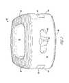
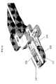
- FIG. 13provides a front view illustrating the anterior side of the ALIF implant 130 .
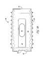
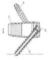
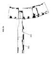
- FIG. 17provides a front view of the ALIF implant 200 and a fastening feature.
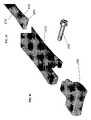
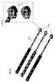
- FIG. 23provides an isometric view of one embodiment of the parallel distraction instrument 310 engaging the ALIF implant 130 .
- the completed paste mixturemay be agitated via a vibrating table, ultrasonic, or similar means for a period of time ranging from about 5 minutes to about 60 minutes to further reduce porosity.
- a vacuummay be applied during the agitation step.
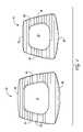
- the bioactive material of the present inventionmay also be formed into an implant ( FIGS. 22A–22D ) suitable for TLIF procedures.
- TLIF implant devicesare generally suitable for implantation in the lumbar regions of the spine.
- the percent relative linear attenuation coefficient, ⁇was calculated as follows:
- the bony endplateswere cleaned and penetrated so that there was vascular blood flow across the endplate.
- the disc spacewas distracted using a distracter instrument.
- Two bioactive spinal implants of the type shown in FIGS. 20–22were placed into the distracted disc space, and carefully impacted.
- a calcium phosphate/bone marrow aspirate (BMA) bone graft materialwas packed around and between the implants in the disc space.
- Specimens without sufficient structural integrity for mechanical testingwere immediately prepared for histologic evaluation. Those with sufficient structural integrity were mechanical tested and then prepared for histological evaluation.
Landscapes
- Health & Medical Sciences (AREA)
- Engineering & Computer Science (AREA)
- Biomedical Technology (AREA)
- Life Sciences & Earth Sciences (AREA)
- Veterinary Medicine (AREA)
- Public Health (AREA)
- General Health & Medical Sciences (AREA)
- Animal Behavior & Ethology (AREA)
- Transplantation (AREA)
- Orthopedic Medicine & Surgery (AREA)
- Chemical & Material Sciences (AREA)
- Heart & Thoracic Surgery (AREA)
- Oral & Maxillofacial Surgery (AREA)
- Vascular Medicine (AREA)
- Neurology (AREA)
- Epidemiology (AREA)
- Medicinal Chemistry (AREA)
- Cardiology (AREA)
- Dermatology (AREA)
- Surgery (AREA)
- Optics & Photonics (AREA)
- Physics & Mathematics (AREA)
- Molecular Biology (AREA)
- Physical Education & Sports Medicine (AREA)
- Inorganic Chemistry (AREA)
- Composite Materials (AREA)
- Materials Engineering (AREA)
- Prostheses (AREA)
- Chemical Kinetics & Catalysis (AREA)
- Polymers & Plastics (AREA)
- Organic Chemistry (AREA)
Abstract
Description
where:
- B=background optical density of 10 mm of Al, in the range of 0.8 to 1.2.
- A=optical density under the 14 mm thickness of Al (4 mm Al sample added to 10 mm Al background), and
- S=optical density of the image of the 4 mm thick sample.
Results
| TABLE 1 |
| Optical density values for three lots of material prior to gamma irradiation. |
| Linear attenuation | |||||
| Lot Number | Sample | Background, B | Sample, S | Aluminum, A | coefficient, α |
| 022601-067 | 1 | 0.89 | 0.76 | 0.58 | 41.94 |
| 2 | 0.86 | 0.73 | 0.57 | 44.83 | |
| 3 | 0.92 | 0.78 | 0.61 | 45.16 | |
| Mean | 0.89 | 0.76 | 0.59 | 43.98 |
| S.D. | 0.03 | 0.03 | 0.02 | 1.77 |
| 022601-074 | 1 | 0.92 | 0.78 | 0.61 | 45.16 |
| 2 | 0.83 | 0.71 | 0.55 | 42.86 | |
| 3 | 0.93 | 0.78 | 0.60 | 45.45 |
| Mean | 0.89 | 0.76 | 0.59 | 44.49 |
| S.D. | 0.06 | 0.04 | 0.03 | 1.42 |
| 032601-082 | 1 | 0.92 | 0.78 | 0.60 | 43.75 |
| 2 | 0.91 | 0.77 | 0.66 | 56.00 | |
| 3 | 0.85 | 0.72 | 0.56 | 44.83 |
| Mean | 0.89 | 0.76 | 0.61 | 48.19 |
| S.D. | 0.04 | 0.03 | 0.05 | 6.78 |
| 022601-067 | Mean | 0.89 | 0.76 | 0.59 | 43.98 |
| 022601-074 | Mean | 0.89 | 0.76 | 0.59 | 44.49 |
| 032601-082 | Mean | 0.89 | 0.76 | 0.61 | 48.19 |
| Mean | 0.89 | 0.76 | 0.60 | 45.55 |
| S.D. | 0.00 | 0.00 | 0.01 | 2.30 |
| TABLE 2 |
| Optical density values for three lots of material after gamma irradiation |
| Linear attenuation | |||||
| Lot Number | Sample | Background, B | Sample, S | Aluminum, A | coefficient, α |
| 022601-067 | 1 | 1.01 | 0.85 | 0.62 | 41.03 |
| 2 | 0.99 | 0.84 | 0.63 | 41.67 | |
| 3 | 1.05 | 0.89 | 0.68 | 43.24 | |
| Mean | 1.02 | 0.86 | 0.64 | 41.98 |
| S.D. | 0.03 | 0.03 | 0.03 | 1.14 |
| 022601-074 | 1 | 1.01 | 0.85 | 0.64 | 43.24 |
| 2 | 1.00 | 0.84 | 0.62 | 42.11 | |
| 3 | 1.01 | 0.85 | 0.64 | 43.24 |
| Mean | 1.01 | 0.85 | 0.63 | 42.86 |
| S.D. | 0.01 | 0.01 | 0.01 | 0.66 |
| 032601-082 | 1 | 0.99 | 0.84 | 0.63 | 41.67 |
| 2 | 0.98 | 0.83 | 0.62 | 41.67 | |
| 3 | 1.01 | 0.83 | 0.64 | 48.65 |
| Mean | 0.99 | 0.83 | 0.63 | 43.99 |
| S.D. | 0.02 | 0.01 | 0.01 | 4.03 |
| 022601-067 | Mean | 1.02 | 0.86 | 0.64 | 41.98 |
| 022601-074 | Mean | 1.01 | 0.85 | 0.63 | 42.86 |
| 032601-082 | Mean | 0.99 | 0.83 | 0.63 | 43.99 |
| Mean | 1.01 | 0.85 | 0.63 | 42.94 |
| S.D. | 0.02 | 0.02 | 0.01 | 1.01 |
Conclusions
| TABLE 3 |
| Mechanical Properties of a Bioactive Spinal Implant Material |
| HUMAN CORTICAL | ||
| TEST | RESULT | BONE |
| Compressive Strength |
| 220–250 | MPa | 167–215 | MPa | |
| ASTM F 451-95 and ASTM | ||||
| D695-91 | ||||
| Compressive Modulus | 7.0–9.0 | GPa | 14.7–19.7 | MPa |
| ASTM F 451-95 and ASTM | ||||
| D695-91 | ||||
| 170–182 | MPa | 121–182 | MPa | |
| ASTM F 451-95 and ASTM | ||||
| D695-91 | ||||
| 65–100 | 70–140 | MPa | ||
| ASTM D638-98 | ||||
| Tensile Elastic Modulus | 14–17 | GPa | 10.9–14.8 | MPa |
| ASTM D638-98 | ||||
| 3- | 100–120 | MPa | 103–238 | MPa |
| ASTM D790-90 | ||||
| Shear by | 60–80 | MPa | 51.6 | MPa |
| ASTM D732-93 | ||||
| 170–190 | MPa | >100 | MPa | |
| (106cycles) | ||||
| 35–55 | MPa | 49 | MPa | |
| (106cycles) | ||||
| TABLE 4 |
| FTIR Peaks of the Material of the Present Invention |
| and Hydroxyapatite |
| ABSORBANCE BAND | |
| (cm−1) |
| HYDROXYAPATITE | RHAKOSS | MOLECULAR ASSIGNMENT |
| — | 3292 | O—H and hydrogen bonding from |
| residual water on the composite | ||
| — | 1632 | Olefin stretch from the composite |
| 1092 | 1075 | Three components of the out of |
| 1014 | 1014 | phase stretch of the phosphate |
| 956 | 960 | ion |
| — | — | Possibly an out of phase deforma- |
| tion band of a carbonate ion result- | ||
| ing from residual SBF salt | ||
| 602 | 598 | A split bending mode of the |
| 559 | 556 | phosphate ion |
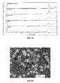
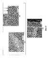
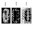
SEM/EDS Results
Claims (17)
Priority Applications (7)
| Application Number | Priority Date | Filing Date | Title |
|---|---|---|---|
| US10/256,566US7238203B2 (en) | 2001-12-12 | 2002-09-26 | Bioactive spinal implants and method of manufacture thereof |
| AU2002357103AAU2002357103A1 (en) | 2001-12-12 | 2002-12-09 | Bioactive spinal implants and method of manufacture thereof |
| PCT/US2002/039184WO2003053290A1 (en) | 2001-12-12 | 2002-12-09 | Bioactive spinal implants and method of manufacture thereof |
| EP02805552AEP1463465B1 (en) | 2001-12-12 | 2002-12-09 | Bioactive spinal implants and method of manufacture thereof |
| US11/736,314US8715353B2 (en) | 2001-12-12 | 2007-04-17 | Bioactive spinal implants and method of manufacture thereof |
| US14/244,354US9211194B2 (en) | 2001-12-12 | 2014-04-03 | Bioactive spinal implants and method of manufacture thereof |
| US14/936,139US9629728B2 (en) | 2001-12-12 | 2015-11-09 | Bioactive spinal implants and method of manufacture thereof |
Applications Claiming Priority (2)
| Application Number | Priority Date | Filing Date | Title |
|---|---|---|---|
| US33987101P | 2001-12-12 | 2001-12-12 | |
| US10/256,566US7238203B2 (en) | 2001-12-12 | 2002-09-26 | Bioactive spinal implants and method of manufacture thereof |
Related Child Applications (1)
| Application Number | Title | Priority Date | Filing Date |
|---|---|---|---|
| US11/736,314DivisionUS8715353B2 (en) | 2001-12-12 | 2007-04-17 | Bioactive spinal implants and method of manufacture thereof |
Publications (2)
| Publication Number | Publication Date |
|---|---|
| US20030125739A1 US20030125739A1 (en) | 2003-07-03 |
| US7238203B2true US7238203B2 (en) | 2007-07-03 |
Family
ID=26945454
Family Applications (4)
| Application Number | Title | Priority Date | Filing Date |
|---|---|---|---|
| US10/256,566Expired - Fee RelatedUS7238203B2 (en) | 2001-12-12 | 2002-09-26 | Bioactive spinal implants and method of manufacture thereof |
| US11/736,314Active2028-07-15US8715353B2 (en) | 2001-12-12 | 2007-04-17 | Bioactive spinal implants and method of manufacture thereof |
| US14/244,354Expired - Fee RelatedUS9211194B2 (en) | 2001-12-12 | 2014-04-03 | Bioactive spinal implants and method of manufacture thereof |
| US14/936,139Expired - Fee RelatedUS9629728B2 (en) | 2001-12-12 | 2015-11-09 | Bioactive spinal implants and method of manufacture thereof |
Family Applications After (3)
| Application Number | Title | Priority Date | Filing Date |
|---|---|---|---|
| US11/736,314Active2028-07-15US8715353B2 (en) | 2001-12-12 | 2007-04-17 | Bioactive spinal implants and method of manufacture thereof |
| US14/244,354Expired - Fee RelatedUS9211194B2 (en) | 2001-12-12 | 2014-04-03 | Bioactive spinal implants and method of manufacture thereof |
| US14/936,139Expired - Fee RelatedUS9629728B2 (en) | 2001-12-12 | 2015-11-09 | Bioactive spinal implants and method of manufacture thereof |
Country Status (4)
| Country | Link |
|---|---|
| US (4) | US7238203B2 (en) |
| EP (1) | EP1463465B1 (en) |
| AU (1) | AU2002357103A1 (en) |
| WO (1) | WO2003053290A1 (en) |
Cited By (256)
| Publication number | Priority date | Publication date | Assignee | Title |
|---|---|---|---|---|
| US20040148027A1 (en)* | 2001-07-16 | 2004-07-29 | Errico Joseph P. | Intervertebral spacer device having an engagement hole for manipulation using a surgical tool |
| US20050060035A1 (en)* | 2001-07-16 | 2005-03-17 | Errico Joseph P. | Intervertebral spacer device having recessed notch pairs for manipulation using a surgical tool |
| US20050112186A1 (en)* | 2003-10-29 | 2005-05-26 | David Devore | Polymerizable emulsions for tissue engineering |
| US20050251257A1 (en)* | 2004-05-04 | 2005-11-10 | Mitchell Margaret E | Spinal implants with body and insert |
| US20060276907A1 (en)* | 2000-03-22 | 2006-12-07 | Boyer Michael L Ii | Multipiece implants formed of bone material |
| US20070016221A1 (en)* | 1999-09-14 | 2007-01-18 | Boris Beyersdorff | Insertion instrument for an intervertebral implant |
| US20070123906A1 (en)* | 2001-07-16 | 2007-05-31 | Spinecore, Inc. | Inserter/impactor for implanting an artificial intervertebral disc |
| US20070141110A1 (en)* | 2004-12-09 | 2007-06-21 | Biomet Sports Medicine, Inc. | Continuous phase compositions for ACL repair |
| US20070156171A1 (en)* | 2001-05-25 | 2007-07-05 | Conformis, Inc. | Implant Grasper |
| US20070156243A1 (en)* | 2001-07-16 | 2007-07-05 | Spinecore, Inc. | Intervertebral spacer device having engagement hole pairs |
| US20080132949A1 (en)* | 2005-12-29 | 2008-06-05 | Joseph Aferzon | Apparatus and method for anterior intervertebral spinal fixation and fusion |
| US20080200985A1 (en)* | 2007-02-19 | 2008-08-21 | Zimmer Spine, Inc. | Spinal implant |
| US20080208342A1 (en)* | 2007-02-27 | 2008-08-28 | Zimmer Spine, Inc. | Spinal implant |
| US20080275562A1 (en)* | 2007-05-01 | 2008-11-06 | Exploramed Nc4, Inc. | Femoral and tibial base components |
| US20080275558A1 (en)* | 2007-05-01 | 2008-11-06 | Exploramed Nc4, Inc. | Extra-articular implantable mechanical energy absorbing systems and implantation method |
| US20080275563A1 (en)* | 2007-05-01 | 2008-11-06 | Exploramed Nc4, Inc. | Adjustable absorber designs for implantable device |
| US20080306598A1 (en)* | 2007-04-02 | 2008-12-11 | Eric Hansen | Spinal implant with biologic sponge |
| US20090018656A1 (en)* | 2007-07-09 | 2009-01-15 | Exploramed Nc4, Inc. | Surgical implantation method and devices for an extra-articular mechanical energy absorbing apparatus |
| US20090014016A1 (en)* | 2007-07-09 | 2009-01-15 | Exploramed Nc4, Inc. | Surgical implantation method and devices for an extra-articular mechanical energy absorbing apparatus |
| US20090062917A1 (en)* | 2007-08-27 | 2009-03-05 | Foley Kevin T | Spinal interbody replacement devices |
| US7537616B1 (en)* | 1999-10-20 | 2009-05-26 | Warsaw Orthopedic, Inc. | Impacted orthopedic bone support implant |
| US20090138096A1 (en)* | 2004-12-08 | 2009-05-28 | Myerson Mark S | Foot/ankle implant and associated method |
| US20090228113A1 (en)* | 2008-03-05 | 2009-09-10 | Comformis, Inc. | Edge-Matched Articular Implant |
| US20090248163A1 (en)* | 2008-03-31 | 2009-10-01 | King Emily E | Spinal surgery interbody |
| US20090254182A1 (en)* | 2008-04-02 | 2009-10-08 | John Kovarik | Intervertebral implant devices for supporting vertebrae and devices and methods for insertion thereof |
| US20100049322A1 (en)* | 2008-08-19 | 2010-02-25 | Warsaw Orthopedic, Inc. | Osteochondral repair implants and methods |
| US20100057206A1 (en)* | 2008-09-02 | 2010-03-04 | Duffield William E | Intervertebral fusion implant |
| US20100106247A1 (en)* | 2007-05-01 | 2010-04-29 | Moximed, Inc. | Extra-Articular Implantable Mechanical Energy Absorbing Systems |
| US7708780B2 (en) | 2003-03-06 | 2010-05-04 | Spinecore, Inc. | Instrumentation and methods for use in implanting a cervical disc replacement device |
| US7713302B2 (en) | 2001-10-01 | 2010-05-11 | Spinecore, Inc. | Intervertebral spacer device utilizing a spirally slotted belleville washer having radially spaced concentric grooves |
| USD616546S1 (en)* | 2009-03-04 | 2010-05-25 | Verticor, Ltd. | Intervertebral implant |
| US20100129416A1 (en)* | 2006-09-25 | 2010-05-27 | Orthovita, Inc | Bioactive load-bearing composites |
| US20100168798A1 (en)* | 2008-12-30 | 2010-07-01 | Clineff Theodore D | Bioactive composites of polymer and glass and method for making same |
| USD619255S1 (en)* | 2008-07-26 | 2010-07-06 | Ulrich Gmbh & Co. Kg | Spinal implant |
| USD620111S1 (en)* | 2008-12-02 | 2010-07-20 | Eminent Spine Llc | Interbody fusion device implant |
| US7771477B2 (en) | 2001-10-01 | 2010-08-10 | Spinecore, Inc. | Intervertebral spacer device utilizing a belleville washer having radially spaced concentric grooves |
| USD623750S1 (en)* | 2009-11-05 | 2010-09-14 | Duffield William E | Intervertebral fusion implant |
| US20100241231A1 (en)* | 2009-02-20 | 2010-09-23 | Marino James F | Intervertebral fixation device |
| US7803162B2 (en) | 2003-07-21 | 2010-09-28 | Spine Solutions, Inc. | Instruments and method for inserting an intervertebral implant |
| US20100247600A1 (en)* | 2009-03-24 | 2010-09-30 | Warsaw Orthopedic, Inc. | Therapeutic drug eluting implant cover and method of making the same |
| US20100262245A1 (en)* | 2009-02-18 | 2010-10-14 | Alfaro Arthur A | Intervertebral spacer |
| USD627466S1 (en)* | 2008-12-02 | 2010-11-16 | Eminent Spine Llc | Interbody fusion device implant |
| US20100312345A1 (en)* | 2009-06-04 | 2010-12-09 | Duffield William E | Intervertebral fusion implant |
| USD630749S1 (en)* | 2008-10-24 | 2011-01-11 | Alain Tornier | Intersomatic cage |
| US20110029081A1 (en)* | 2000-12-14 | 2011-02-03 | Depuy Spine, Inc. | Devices and methods for facilitating controlled bone growth or repair |
| US7887595B1 (en) | 2005-12-05 | 2011-02-15 | Nuvasive, Inc. | Methods and apparatus for spinal fusion |
| US20110039974A1 (en)* | 2007-03-20 | 2011-02-17 | Franz Vekoerrer | Composite material |
| US20110046744A1 (en)* | 2001-07-16 | 2011-02-24 | Spinecore, Inc. | Intervertebral spacer device having recessed notch pairs for manipulation using a surgical tool |
| WO2010138627A3 (en)* | 2009-05-29 | 2011-04-21 | The Regents Of The University Of California | A method of enhancing bioactivity of implant materials |
| US20110112643A1 (en)* | 2005-09-26 | 2011-05-12 | Schwab Frank J | Hybrid Intervertebral Spinal Fusion Implant |
| US20110118843A1 (en)* | 2002-02-19 | 2011-05-19 | Claude Mathieu | Intervertebral implant |
| US20110160860A1 (en)* | 2009-12-31 | 2011-06-30 | Rhausler, Inc. | Cervical spacer |
| US20110190903A1 (en)* | 2004-12-08 | 2011-08-04 | Biomet Manufacturing Corp. | Continuous phase composite for musculoskeletal repair |
| US20110230970A1 (en)* | 2010-03-16 | 2011-09-22 | Pinnacle Spine Group, Llc | Intervertebral implants and graft delivery systems and methods |
| US8029568B2 (en) | 2001-10-18 | 2011-10-04 | Spinecore, Inc. | Intervertebral spacer device having a slotted partial circular domed arch strip spring |
| US20110295327A1 (en)* | 2005-04-12 | 2011-12-01 | Moskowitz Ahmnon D | Bi-directional fixating transvertebral body screws and posterior cervical and lumbar interarticulating joint calibrated stapling devices for spinal fusion |
| US8077950B2 (en) | 2002-11-07 | 2011-12-13 | Conformis, Inc. | Methods for determining meniscal size and shape and for devising treatment |
| US8088166B2 (en) | 2007-05-01 | 2012-01-03 | Moximed, Inc. | Adjustable absorber designs for implantable device |
| US8088163B1 (en) | 2008-02-06 | 2012-01-03 | Kleiner Jeffrey B | Tools and methods for spinal fusion |
| US8105381B2 (en) | 2002-12-13 | 2012-01-31 | Spine Solutions, Inc. | Intervertebral implant, insertion tool and method of inserting same |
| US8114162B1 (en) | 2006-08-09 | 2012-02-14 | Nuvasive, Inc. | Spinal fusion implant and related methods |
| US20120065733A1 (en)* | 2010-09-13 | 2012-03-15 | Brian Howard Wieder | Inter-vertebral implant having drain cavities therethrough |
| USD656610S1 (en) | 2009-02-06 | 2012-03-27 | Kleiner Jeffrey B | Spinal distraction instrument |
| US20120078370A1 (en)* | 2010-08-31 | 2012-03-29 | James Stephen B | Spinal implants |
| US20120095559A1 (en)* | 2010-10-18 | 2012-04-19 | Woods John C | Intervertebral spinal implant, installation device and system |
| US20120136392A1 (en)* | 2009-03-16 | 2012-05-31 | Synthes Usa, Llc | System and Method for Stabilizing Vertebrae in Spine Surgery Through a Lateral Access Channel |
| US8202299B2 (en)* | 2008-03-19 | 2012-06-19 | Collabcom II, LLC | Interspinous implant, tools and methods of implanting |
| US8234097B2 (en) | 2001-05-25 | 2012-07-31 | Conformis, Inc. | Automated systems for manufacturing patient-specific orthopedic implants and instrumentation |
| US8277507B2 (en) | 2002-04-12 | 2012-10-02 | Spinecore, Inc. | Spacerless artificial disc replacements |
| US8282682B2 (en) | 2003-09-30 | 2012-10-09 | X-Spine Systems, Inc. | Fusion system and method for fusing spinal bones |
| US8337507B2 (en) | 2001-05-25 | 2012-12-25 | Conformis, Inc. | Methods and compositions for articular repair |
| US8337500B2 (en) | 2006-07-31 | 2012-12-25 | Synthes Usa, Llc | Drilling/milling guide and keel cut preparation system |
| US8357167B2 (en) | 2001-07-16 | 2013-01-22 | Spinecore, Inc. | Artificial intervertebral disc trials with baseplates having inward tool engagement holes |
| US8366748B2 (en) | 2008-12-05 | 2013-02-05 | Kleiner Jeffrey | Apparatus and method of spinal implant and fusion |
| US20130053894A1 (en)* | 2011-08-31 | 2013-02-28 | Depuy Spine, Inc. | Devices and methods for cervical lateral fixation |
| US8425603B2 (en) | 2008-12-22 | 2013-04-23 | Synthes Usa, Llc | Orthopedic implant with flexible keel |
| US8454694B2 (en) | 2011-03-03 | 2013-06-04 | Warsaw Orthopedic, Inc. | Interbody device and plate for spinal stabilization and instruments for positioning same |
| US8470041B2 (en) | 2002-04-12 | 2013-06-25 | Spinecore, Inc. | Two-component artificial disc replacements |
| US8480754B2 (en) | 2001-05-25 | 2013-07-09 | Conformis, Inc. | Patient-adapted and improved articular implants, designs and related guide tools |
| US8480747B2 (en) | 2010-08-11 | 2013-07-09 | Warsaw Orthopedic, Inc. | Interbody spinal implants with extravertebral support plates |
| US20130197643A1 (en)* | 2012-01-31 | 2013-08-01 | Blackstone Medical, Inc. | Intervertebral disc prosthesis and method |
| US8506634B2 (en) | 1999-07-02 | 2013-08-13 | DePuy Synthes Products, LLC | Intervertebral implant |
| US8545569B2 (en) | 2001-05-25 | 2013-10-01 | Conformis, Inc. | Patient selectable knee arthroplasty devices |
| US8556983B2 (en) | 2001-05-25 | 2013-10-15 | Conformis, Inc. | Patient-adapted and improved orthopedic implants, designs and related tools |
| WO2013158801A1 (en)* | 2012-04-17 | 2013-10-24 | Aurora Spine, Llc | A dynamic and non-dynamic interspinous fusion implant and bone growth stimulation system |
| US8579911B2 (en) | 2008-01-18 | 2013-11-12 | Spinecore, Inc. | Instruments and methods for inserting artificial intervertebral implants |
| US8597362B2 (en) | 2009-08-27 | 2013-12-03 | Cotera, Inc. | Method and apparatus for force redistribution in articular joints |
| US8617242B2 (en) | 2001-05-25 | 2013-12-31 | Conformis, Inc. | Implant device and method for manufacture |
| US8623088B1 (en) | 2005-07-15 | 2014-01-07 | Nuvasive, Inc. | Spinal fusion implant and related methods |
| US20140031937A1 (en)* | 2012-07-26 | 2014-01-30 | Warsaw Orthopedic, Inc. | Bone implant device |
| US8663229B2 (en) | 2003-04-28 | 2014-03-04 | DePuy Synthes Products, LLC | Instruments and method for preparing an intervertebral space for receiving an artificial disc implant |
| US8682052B2 (en) | 2008-03-05 | 2014-03-25 | Conformis, Inc. | Implants for altering wear patterns of articular surfaces |
| US8685031B2 (en) | 2009-09-18 | 2014-04-01 | Spinal Surgical Strategies, Llc | Bone graft delivery system |
| US20140114415A1 (en)* | 2012-10-19 | 2014-04-24 | Jeffrey Tyber | Orthopedic Systems for Spine and Tracking Control |
| US8709089B2 (en) | 2002-10-07 | 2014-04-29 | Conformis, Inc. | Minimally invasive joint implant with 3-dimensional geometry matching the articular surfaces |
| US8735773B2 (en) | 2007-02-14 | 2014-05-27 | Conformis, Inc. | Implant device and method for manufacture |
| US8765189B2 (en) | 2011-05-13 | 2014-07-01 | Howmedica Osteonic Corp. | Organophosphorous and multivalent metal compound compositions and methods |
| USD708747S1 (en) | 2006-09-25 | 2014-07-08 | Nuvasive, Inc. | Spinal fusion implant |
| US8771365B2 (en) | 2009-02-25 | 2014-07-08 | Conformis, Inc. | Patient-adapted and improved orthopedic implants, designs, and related tools |
| US8777959B2 (en) | 2005-05-27 | 2014-07-15 | Spinecore, Inc. | Intervertebral disc and insertion methods therefor |
| USD711537S1 (en)* | 2009-10-14 | 2014-08-19 | Nuvasive, Inc. | Intervertebral implant |
| US8845724B2 (en) | 2009-08-27 | 2014-09-30 | Cotera, Inc. | Method and apparatus for altering biomechanics of the articular joints |
| US8852280B2 (en) | 2007-09-27 | 2014-10-07 | Warsaw Orthopedic, Inc. | Intervertebral implant |
| US8864654B2 (en) | 2010-04-20 | 2014-10-21 | Jeffrey B. Kleiner | Method and apparatus for performing retro peritoneal dissection |
| US8882847B2 (en) | 2001-05-25 | 2014-11-11 | Conformis, Inc. | Patient selectable knee joint arthroplasty devices |
| US8888879B1 (en) | 2010-10-20 | 2014-11-18 | Us Synthetic Corporation | Detection of one or more interstitial constituents in a polycrystalline diamond element by neutron radiographic imaging |
| US8894714B2 (en) | 2007-05-01 | 2014-11-25 | Moximed, Inc. | Unlinked implantable knee unloading device |
| US8906028B2 (en) | 2009-09-18 | 2014-12-09 | Spinal Surgical Strategies, Llc | Bone graft delivery device and method of using the same |
| US8940053B2 (en) | 2005-05-06 | 2015-01-27 | Titan Spine, Llc | Spinal implant and integration plate for optimizing vertebral endplate contact load-bearing edges |
| US8956414B2 (en) | 2010-04-21 | 2015-02-17 | Spinecraft, LLC | Intervertebral body implant, instrument and method |
| USD723682S1 (en) | 2013-05-03 | 2015-03-03 | Spinal Surgical Strategies, Llc | Bone graft delivery tool |
| US8992622B2 (en) | 2005-05-06 | 2015-03-31 | Titan Spine, Llc | Interbody spinal implant having a roughened surface topography |
| WO2015047704A1 (en)* | 2013-09-26 | 2015-04-02 | Warsaw Orthopedic, Inc. | Intrabody osteotomy implant and methods of use |
| US8998990B2 (en) | 2006-07-24 | 2015-04-07 | DePuy Synthes Products, LLC | Intervertebral implant with keel |
| US9020788B2 (en) | 1997-01-08 | 2015-04-28 | Conformis, Inc. | Patient-adapted and improved articular implants, designs and related guide tools |
| US9044270B2 (en) | 2011-03-29 | 2015-06-02 | Moximed, Inc. | Apparatus for controlling a load on a hip joint |
| USD731063S1 (en) | 2009-10-13 | 2015-06-02 | Nuvasive, Inc. | Spinal fusion implant |
| US9060877B2 (en) | 2009-09-18 | 2015-06-23 | Spinal Surgical Strategies, Llc | Fusion cage with combined biological delivery system |
| US9078712B2 (en) | 2009-04-15 | 2015-07-14 | Warsaw Orthopedic, Inc. | Preformed drug-eluting device to be affixed to an anterior spinal plate |
| USD735860S1 (en)* | 2013-01-25 | 2015-08-04 | Alliance Partners, Llc | Spinal fusion device |
| USD735859S1 (en)* | 2013-01-25 | 2015-08-04 | Alliance Partners, Llc | Spinal fusion device |
| USD736384S1 (en)* | 2013-01-25 | 2015-08-11 | Alliance Partners, Llc | Spinal fusion device |
| US9138331B2 (en) | 2011-02-15 | 2015-09-22 | Joshua Michael Aferzon | Anterior intervertebral fusion with fixation system, device, and method |
| US9149365B2 (en) | 2013-03-05 | 2015-10-06 | Globus Medical, Inc. | Low profile plate |
| US9155631B2 (en) | 2010-04-08 | 2015-10-13 | Globus Medical Inc. | Intervertbral implant |
| USD741488S1 (en) | 2006-07-17 | 2015-10-20 | Nuvasive, Inc. | Spinal fusion implant |
| US9173694B2 (en) | 2009-09-18 | 2015-11-03 | Spinal Surgical Strategies, Llc | Fusion cage with combined biological delivery system |
| US9186193B2 (en) | 2009-09-18 | 2015-11-17 | Spinal Surgical Strategies, Llc | Fusion cage with combined biological delivery system |
| US9192419B2 (en) | 2008-11-07 | 2015-11-24 | DePuy Synthes Products, Inc. | Zero-profile interbody spacer and coupled plate assembly |
| US9220604B2 (en) | 2010-12-21 | 2015-12-29 | DePuy Synthes Products, Inc. | Intervertebral implants, systems, and methods of use |
| US9237957B2 (en) | 2011-09-16 | 2016-01-19 | Globus Medical, Inc. | Low profile plate |
| US9241809B2 (en) | 2010-12-21 | 2016-01-26 | DePuy Synthes Products, Inc. | Intervertebral implants, systems, and methods of use |
| US9248028B2 (en) | 2011-09-16 | 2016-02-02 | DePuy Synthes Products, Inc. | Removable, bone-securing cover plate for intervertebral fusion cage |
| US9247943B1 (en) | 2009-02-06 | 2016-02-02 | Kleiner Intellectual Property, Llc | Devices and methods for preparing an intervertebral workspace |
| USD750249S1 (en) | 2014-10-20 | 2016-02-23 | Spinal Surgical Strategies, Llc | Expandable fusion cage |
| US9265857B2 (en) | 2010-05-11 | 2016-02-23 | Howmedica Osteonics Corp. | Organophosphorous, multivalent metal compounds, and polymer adhesive interpenetrating network compositions and methods |
| US9277946B2 (en) | 2011-09-06 | 2016-03-08 | Amendia, Inc. | Spinal fusion system |
| US9308091B2 (en) | 2001-05-25 | 2016-04-12 | Conformis, Inc. | Devices and methods for treatment of facet and other joints |
| US9326861B2 (en) | 2012-08-03 | 2016-05-03 | Globus Medical, Inc. | Stabilizing joints |
| US20160128844A1 (en)* | 2012-10-19 | 2016-05-12 | Tyber Medical Llc | System and Method for Correcting Scoliosis |
| US20160151167A1 (en)* | 2014-12-01 | 2016-06-02 | Dae Jean JO | Intervertebral cage for spinal implant |
| US9380932B1 (en) | 2011-11-02 | 2016-07-05 | Pinnacle Spine Group, Llc | Retractor devices for minimally invasive access to the spine |
| US9398957B2 (en) | 2007-05-01 | 2016-07-26 | Moximed, Inc. | Femoral and tibial bases |
| US9408718B2 (en) | 2009-12-31 | 2016-08-09 | Rhausler, Inc. | Inter-vertebral implant with angled plate |
| US9414864B2 (en) | 2009-04-15 | 2016-08-16 | Warsaw Orthopedic, Inc. | Anterior spinal plate with preformed drug-eluting device affixed thereto |
| US9463097B2 (en) | 2003-02-06 | 2016-10-11 | DePuy Synthes Products, Inc. | Intervertebral implant |
| US9468466B1 (en) | 2012-08-24 | 2016-10-18 | Cotera, Inc. | Method and apparatus for altering biomechanics of the spine |
| US9486327B2 (en) | 2014-05-15 | 2016-11-08 | Globus Medical, Inc. | Standalone interbody implants |
| US9498349B2 (en) | 2012-10-09 | 2016-11-22 | Titan Spine, Llc | Expandable spinal implant with expansion wedge and anchor |
| US9526620B2 (en) | 2009-03-30 | 2016-12-27 | DePuy Synthes Products, Inc. | Zero profile spinal fusion cage |
| US9532821B2 (en) | 2005-04-12 | 2017-01-03 | Nathan C. Moskowitz | Bi-directional fixating/locking transvertebral body screw/intervertebral cage stand-alone constructs with vertical hemi-bracket screw locking mechanism |
| US9539109B2 (en) | 2011-09-16 | 2017-01-10 | Globus Medical, Inc. | Low profile plate |
| US9545320B2 (en) | 2014-05-15 | 2017-01-17 | Globus Medical, Inc. | Standalone interbody implants |
| US9603713B2 (en) | 2005-04-12 | 2017-03-28 | Nathan C. Moskowitz | Bi-directional fixating/locking transvertebral body screw/intervertebral cage stand-alone constructs and posterior cervical and lumbar interarticulating joint stapling guns and devices for spinal fusion |
| US9603711B2 (en) | 2001-05-25 | 2017-03-28 | Conformis, Inc. | Patient-adapted and improved articular implants, designs and related guide tools |
| US9615935B2 (en) | 2014-01-30 | 2017-04-11 | Titan Spine, Llc | Thermally activated shape memory spring assemblies for implant expansion |
| US9629729B2 (en) | 2009-09-18 | 2017-04-25 | Spinal Surgical Strategies, Llc | Biological delivery system with adaptable fusion cage interface |
| US9642721B2 (en) | 2012-10-02 | 2017-05-09 | Titan Spine, Llc | Implants with self-deploying anchors |
| US9649200B2 (en)* | 2014-07-28 | 2017-05-16 | Wasaw Orthopedic, Inc. | Spinal implant system and method |
| US9662225B2 (en) | 2012-03-06 | 2017-05-30 | DePuy Synthes Products, Inc. | Nubbed plate |
| US9668868B2 (en) | 2009-08-27 | 2017-06-06 | Cotera, Inc. | Apparatus and methods for treatment of patellofemoral conditions |
| US9681959B2 (en) | 2011-09-16 | 2017-06-20 | Globus Medical, Inc. | Low profile plate |
| US9687354B2 (en) | 2008-03-26 | 2017-06-27 | DePuy Synthes Products, Inc. | Posterior intervertebral disc inserter and expansion techniques |
| US9713537B2 (en) | 2003-04-21 | 2017-07-25 | Rsb Spine Llc | Bone plate stabilization system and method for its use |
| US9717403B2 (en) | 2008-12-05 | 2017-08-01 | Jeffrey B. Kleiner | Method and apparatus for performing retro peritoneal dissection |
| US9730804B2 (en) | 2009-09-06 | 2017-08-15 | Warsaw Orthopedic, Inc. | Locking spinal fusion device |
| US9744052B2 (en) | 2005-04-12 | 2017-08-29 | Nathan C. Moskowitz | Bi-directional fixating/locking transvertebral body screw/intervertebral cage stand-alone constructs |
| US9744049B2 (en) | 2007-11-16 | 2017-08-29 | DePuy Synthes Products, Inc. | Low profile intervertebral implant |
| USD797290S1 (en) | 2015-10-19 | 2017-09-12 | Spinal Surgical Strategies, Llc | Bone graft delivery tool |
| US9814601B2 (en) | 2005-04-12 | 2017-11-14 | Nathan C. Moskowitz | Bi-directional fixating/locking transvertebral body screw/intervertebral cage stand-alone constructs |
| US9848993B2 (en) | 2005-04-12 | 2017-12-26 | Nathan C. Moskowitz | Zero-profile expandable intervertebral spacer devices for distraction and spinal fusion and a universal tool for their placement and expansion |
| US9848994B2 (en) | 2011-09-16 | 2017-12-26 | Globus Medical, Inc. | Low profile plate |
| US9861408B2 (en) | 2009-08-27 | 2018-01-09 | The Foundry, Llc | Method and apparatus for treating canine cruciate ligament disease |
| US9867718B2 (en) | 2014-10-22 | 2018-01-16 | DePuy Synthes Products, Inc. | Intervertebral implants, systems, and methods of use |
| US9924940B2 (en) | 2005-04-12 | 2018-03-27 | Nathan C. Moskowitz | Bi-directional fixating transvertebral body screws, zero-profile horizontal intervertebral miniplates, expansile intervertebral body fusion devices, and posterior motion-calibrating interarticulating joint stapling device for spinal fusion |
| US9968461B2 (en) | 2014-05-15 | 2018-05-15 | Globus Medical, Inc. | Standalone interbody implants |
| US9987052B2 (en) | 2015-02-24 | 2018-06-05 | X-Spine Systems, Inc. | Modular interspinous fixation system with threaded component |
| US10070970B2 (en) | 2013-03-14 | 2018-09-11 | Pinnacle Spine Group, Llc | Interbody implants and graft delivery systems |
| US10076367B2 (en) | 2005-04-12 | 2018-09-18 | Moskowitz Family Llc | Bi-directional fixating transvertebral body screws, zero-profile horizontal intervertebral miniplates, total intervertebral body fusion devices, and posterior motion-calibrating interarticulating joint stapling device for spinal fusion |
| US10085839B2 (en) | 2004-01-05 | 2018-10-02 | Conformis, Inc. | Patient-specific and patient-engineered orthopedic implants |
| US10123881B2 (en) | 2006-04-20 | 2018-11-13 | Moskowitz Family Llc | Electronically controlled artificial intervertebral disc with motor assisted actuation systems |
| US10182923B2 (en) | 2015-01-14 | 2019-01-22 | Stryker European Holdings I, Llc | Spinal implant with porous and solid surfaces |
| US10182921B2 (en) | 2012-11-09 | 2019-01-22 | DePuy Synthes Products, Inc. | Interbody device with opening to allow packing graft and other biologics |
| US10206787B2 (en) | 2006-12-22 | 2019-02-19 | Medos International Sarl | Composite vertebral spacers and instrument |
| US10245155B2 (en) | 2011-09-16 | 2019-04-02 | Globus Medical, Inc. | Low profile plate |
| US10245159B1 (en) | 2009-09-18 | 2019-04-02 | Spinal Surgical Strategies, Llc | Bone graft delivery system and method for using same |
| US10271959B2 (en) | 2009-02-11 | 2019-04-30 | Howmedica Osteonics Corp. | Intervertebral implant with integrated fixation |
| US10271960B2 (en) | 2017-04-05 | 2019-04-30 | Globus Medical, Inc. | Decoupled spacer and plate and method of installing the same |
| US10335289B2 (en) | 2010-09-23 | 2019-07-02 | DePuy Synthes Products, Inc. | Stand alone intervertebral fusion device |
| USD853560S1 (en) | 2008-10-09 | 2019-07-09 | Nuvasive, Inc. | Spinal implant insertion device |
| US10349980B2 (en) | 2009-08-27 | 2019-07-16 | The Foundry, Llc | Method and apparatus for altering biomechanics of the shoulder |
| US10369015B2 (en) | 2010-09-23 | 2019-08-06 | DePuy Synthes Products, Inc. | Implant inserter having a laterally-extending dovetail engagement feature |
| US10376385B2 (en) | 2017-04-05 | 2019-08-13 | Globus Medical, Inc. | Decoupled spacer and plate and method of installing the same |
| US10383736B2 (en) | 2007-05-01 | 2019-08-20 | Moximed, Inc. | Femoral and tibial base components |
| USD858769S1 (en) | 2014-11-20 | 2019-09-03 | Nuvasive, Inc. | Intervertebral implant |
| US10492917B2 (en) | 2013-09-26 | 2019-12-03 | Warsaw Orthopedic, Inc. | Intrabody osteotomy implant and methods of use |
| US10500062B2 (en) | 2009-12-10 | 2019-12-10 | DePuy Synthes Products, Inc. | Bellows-like expandable interbody fusion cage |
| US10512548B2 (en) | 2006-02-27 | 2019-12-24 | DePuy Synthes Products, Inc. | Intervertebral implant with fixation geometry |
| US10517739B2 (en) | 2018-05-08 | 2019-12-31 | Globus Medical, Inc. | Intervertebral spinal implant |
| US10537666B2 (en) | 2015-05-18 | 2020-01-21 | Stryker European Holdings I, Llc | Partially resorbable implants and methods |
| US10603182B2 (en) | 2015-01-14 | 2020-03-31 | Stryker European Holdings I, Llc | Spinal implant with fluid delivery capabilities |
| US10682238B2 (en) | 2018-05-08 | 2020-06-16 | Globus Medical, Inc. | Intervertebral spinal implant |
| US10744003B2 (en) | 2018-05-08 | 2020-08-18 | Globus Medical, Inc. | Intervertebral spinal implant |
| US20200282105A1 (en)* | 2013-03-15 | 2020-09-10 | Beacon Biomedical, Llc | Spinal implants with bioactive glass markers |
| US10835388B2 (en) | 2017-09-20 | 2020-11-17 | Stryker European Operations Holdings Llc | Spinal implants |
| US10856997B2 (en) | 2018-02-22 | 2020-12-08 | Warsaw Orthopedic, Inc. | Expandable spinal implant system and method of using same |
| US10864081B2 (en) | 2012-10-19 | 2020-12-15 | Tyber Medical, LLC | Wedge osteotomy device and method of use |
| USD907771S1 (en) | 2017-10-09 | 2021-01-12 | Pioneer Surgical Technology, Inc. | Intervertebral implant |
| US10940016B2 (en) | 2017-07-05 | 2021-03-09 | Medos International Sarl | Expandable intervertebral fusion cage |
| US10966835B2 (en) | 2017-03-29 | 2021-04-06 | Stryker European Holdings I, Llc | Spinal implant system |
| US10973656B2 (en) | 2009-09-18 | 2021-04-13 | Spinal Surgical Strategies, Inc. | Bone graft delivery system and method for using same |
| US11020239B2 (en) | 2018-02-22 | 2021-06-01 | Warsaw Orthopedic, Inc. | Expandable spinal implant system and method of using same |
| US11039931B2 (en) | 2019-02-01 | 2021-06-22 | Globus Medical, Inc. | Intervertebral spinal implant |
| US11045328B2 (en) | 2018-09-07 | 2021-06-29 | Additive Implants, Inc. | Dynamic intervertebral spacer implant |
| US11065126B2 (en) | 2018-08-09 | 2021-07-20 | Stryker European Operations Holdings Llc | Interbody implants and optimization features thereof |
| US11123201B2 (en) | 2019-09-24 | 2021-09-21 | Additive Implants, Inc. | Intervertebral spacer |
| US11147682B2 (en) | 2017-09-08 | 2021-10-19 | Pioneer Surgical Technology, Inc. | Intervertebral implants, instruments, and methods |
| US11160666B2 (en) | 2014-05-15 | 2021-11-02 | Globus Medical, Inc. | Laterally insertable intervertebral spinal implant |
| US11197763B2 (en) | 2010-12-16 | 2021-12-14 | Engage Medical Holdings, Llc | Arthroplasty systems and methods |
| US11234838B2 (en) | 2018-09-07 | 2022-02-01 | Additive Implants, Inc. | Dynamic intervertebral spacer implant |
| US11285014B1 (en) | 2020-11-05 | 2022-03-29 | Warsaw Orthopedic, Inc. | Expandable inter-body device, system, and method |
| US11291554B1 (en) | 2021-05-03 | 2022-04-05 | Medtronic, Inc. | Unibody dual expanding interbody implant |
| USD948048S1 (en) | 2019-04-26 | 2022-04-05 | Warsaw Orthopedic, Inc. | Surgical implant |
| USD955579S1 (en) | 2019-04-26 | 2022-06-21 | Warsaw Orthopedic, Inc. | Surgical implant |
| US11369488B2 (en) | 2017-03-03 | 2022-06-28 | Engage Uni Llc | Unicompartmental knee arthroplasty |
| US11376134B1 (en) | 2020-11-05 | 2022-07-05 | Warsaw Orthopedic, Inc. | Dual expanding spinal implant, system, and method of use |
| USD957639S1 (en) | 2013-03-15 | 2022-07-12 | Medtronic, Inc. | Implantable cardiac monitor |
| US11395743B1 (en) | 2021-05-04 | 2022-07-26 | Warsaw Orthopedic, Inc. | Externally driven expandable interbody and related methods |
| US11413371B2 (en)* | 2013-10-15 | 2022-08-16 | Tyber Medical, LLC | System and method for correcting scoliosis |
| US11517443B2 (en) | 2020-11-05 | 2022-12-06 | Warsaw Orthopedic, Inc. | Dual wedge expandable implant, system and method of use |
| US11529241B2 (en) | 2010-09-23 | 2022-12-20 | DePuy Synthes Products, Inc. | Fusion cage with in-line single piece fixation |
| US11540928B2 (en) | 2017-03-03 | 2023-01-03 | Engage Uni Llc | Unicompartmental knee arthroplasty |
| US11547569B2 (en)* | 2012-10-19 | 2023-01-10 | Tyber Medical Llc | Anatomical wedge implant |
| US11564724B2 (en) | 2020-11-05 | 2023-01-31 | Warsaw Orthopedic, Inc. | Expandable inter-body device, system and method |
| US11612499B2 (en) | 2021-06-24 | 2023-03-28 | Warsaw Orthopedic, Inc. | Expandable interbody implant |
| US11638653B2 (en) | 2020-11-05 | 2023-05-02 | Warsaw Orthopedic, Inc. | Surgery instruments with a movable handle |
| US11666455B2 (en) | 2009-09-18 | 2023-06-06 | Spinal Surgical Strategies, Inc., A Nevada Corporation | Bone graft delivery devices, systems and kits |
| US11684482B2 (en) | 2018-12-20 | 2023-06-27 | Additive Implants, Inc. | Spondylolisthesis system and methods |
| US11717417B2 (en) | 2011-09-16 | 2023-08-08 | Globus Medical Inc. | Low profile plate |
| US11730608B2 (en) | 2021-07-13 | 2023-08-22 | Warsaw Orthopedic, Inc. | Monoblock expandable interbody implant |
| US11779378B2 (en) | 2019-01-11 | 2023-10-10 | Medcom Advisors, Llc | Self-aligning plating system and method |
| US11806250B2 (en) | 2018-02-22 | 2023-11-07 | Warsaw Orthopedic, Inc. | Expandable spinal implant system and method of using same |
| US11833059B2 (en) | 2020-11-05 | 2023-12-05 | Warsaw Orthopedic, Inc. | Expandable inter-body device, expandable plate system, and associated methods |
| US11850163B2 (en) | 2022-02-01 | 2023-12-26 | Warsaw Orthopedic, Inc. | Interbody implant with adjusting shims |
| US11903849B2 (en) | 2005-04-12 | 2024-02-20 | Moskowitz Family Llc | Intervertebral implant and tool assembly |
| US11963881B2 (en) | 2020-11-05 | 2024-04-23 | Warsaw Orthopedic, Inc. | Expandable inter-body device, system, and method |
| US12121453B2 (en) | 2020-11-05 | 2024-10-22 | Warsaw Orthopedic, Inc. | Dual wedge expandable implant with eyelets, system, and method of use |
| US12171439B2 (en) | 2020-11-05 | 2024-12-24 | Warsaw Orthopedic, Inc. | Protected drill |
| US12239544B2 (en) | 2020-11-05 | 2025-03-04 | Warsaw Orthopedic, Inc. | Rhomboid shaped implants |
| US12268614B2 (en) | 2021-06-24 | 2025-04-08 | Warsaw Orthopedic, Inc. | Interbody implant with adjusting shims |
| US12279972B2 (en) | 2008-05-22 | 2025-04-22 | Spinal Surgical Strategies, Inc. | Spinal fusion cage system with inserter |
| US12295865B2 (en) | 2021-06-24 | 2025-05-13 | Warsaw Orthopedic, Inc. | Expandable interbody implant and corresponding inserter |
| US12318308B2 (en) | 2020-11-05 | 2025-06-03 | Warsaw Orthopedic, Inc. | Dual expandable inter-body device |
| US12414863B2 (en) | 2021-06-24 | 2025-09-16 | Warsaw Orthopedic, Inc. | Expandable interbody implant and corresponding surgical tool |
| USD1095838S1 (en)* | 2021-10-15 | 2025-09-30 | Rv Medical Llc | Interbody device |
| US12440349B2 (en) | 2022-02-04 | 2025-10-14 | Warsaw Orthopedic, Inc. | Expandable interbody implant and breakoff screw |
Families Citing this family (279)
| Publication number | Priority date | Publication date | Assignee | Title |
|---|---|---|---|---|
| FR2767675B1 (en)* | 1997-08-26 | 1999-12-03 | Materiel Orthopedique En Abreg | INTERSOMATIC IMPLANT AND ANCILLARY OF PREPARATION SUITABLE FOR ALLOWING ITS POSITION |
| US6458162B1 (en) | 1999-08-13 | 2002-10-01 | Vita Special Purpose Corporation | Composite shaped bodies and methods for their production and use |
| US7169183B2 (en)* | 2000-03-14 | 2007-01-30 | Warsaw Orthopedic, Inc. | Vertebral implant for promoting arthrodesis of the spine |
| US6875212B2 (en) | 2000-06-23 | 2005-04-05 | Vertelink Corporation | Curable media for implantable medical device |
| US6964667B2 (en) | 2000-06-23 | 2005-11-15 | Sdgi Holdings, Inc. | Formed in place fixation system with thermal acceleration |
| EP1292239B1 (en) | 2000-06-23 | 2013-02-13 | University Of Southern California | Percutaneous vertebral fusion system |
| US6899713B2 (en) | 2000-06-23 | 2005-05-31 | Vertelink Corporation | Formable orthopedic fixation system |
| US7018418B2 (en)* | 2001-01-25 | 2006-03-28 | Tecomet, Inc. | Textured surface having undercut micro recesses in a surface |
| US6989032B2 (en)* | 2001-07-16 | 2006-01-24 | Spinecore, Inc. | Artificial intervertebral disc |
| US7575576B2 (en)* | 2001-07-16 | 2009-08-18 | Spinecore, Inc. | Wedge ramp distractor and related methods for use in implanting artificial intervertebral discs |
| US20070198092A1 (en)* | 2001-07-16 | 2007-08-23 | Spinecore, Inc. | System for inserting artificial intervertebral discs |
| ITRM20010628A1 (en)* | 2001-10-23 | 2003-04-23 | Univ Roma | HIP PROSTHESIS AND RELATED METHOD OF DESIGN. |
| WO2003105670A2 (en) | 2002-01-10 | 2003-12-24 | Guided Delivery Systems, Inc. | Devices and methods for heart valve repair |
| US7077864B2 (en)* | 2002-02-12 | 2006-07-18 | Cross Medical Products, Inc. | Vertebral interbody cage with translatable locking screw |
| US7309358B2 (en)* | 2002-03-21 | 2007-12-18 | Warsaw Orthopedic, Inc. | Vertebral body and disc space replacement devices |
| US6991653B2 (en)* | 2002-03-21 | 2006-01-31 | Sdgi Holdings, Inc. | Vertebral body and disc space replacement devices |
| US6758862B2 (en)* | 2002-03-21 | 2004-07-06 | Sdgi Holdings, Inc. | Vertebral body and disc space replacement devices |
| US6706068B2 (en) | 2002-04-23 | 2004-03-16 | Bret A. Ferree | Artificial disc replacements with natural kinematics |
| US7666193B2 (en) | 2002-06-13 | 2010-02-23 | Guided Delivery Sytems, Inc. | Delivery devices and methods for heart valve repair |
| US20050216078A1 (en)* | 2002-06-13 | 2005-09-29 | Guided Delivery Systems, Inc. | Delivery devices and methods for heart valve repair |
| US7753858B2 (en) | 2002-06-13 | 2010-07-13 | Guided Delivery Systems, Inc. | Delivery devices and methods for heart valve repair |
| US20060122633A1 (en) | 2002-06-13 | 2006-06-08 | John To | Methods and devices for termination |
| US8287555B2 (en) | 2003-02-06 | 2012-10-16 | Guided Delivery Systems, Inc. | Devices and methods for heart valve repair |
| US7753922B2 (en) | 2003-09-04 | 2010-07-13 | Guided Delivery Systems, Inc. | Devices and methods for cardiac annulus stabilization and treatment |
| US7588582B2 (en) | 2002-06-13 | 2009-09-15 | Guided Delivery Systems Inc. | Methods for remodeling cardiac tissue |
| US9949829B2 (en) | 2002-06-13 | 2018-04-24 | Ancora Heart, Inc. | Delivery devices and methods for heart valve repair |
| US7883538B2 (en) | 2002-06-13 | 2011-02-08 | Guided Delivery Systems Inc. | Methods and devices for termination |
| US20050107811A1 (en) | 2002-06-13 | 2005-05-19 | Guided Delivery Systems, Inc. | Delivery devices and methods for heart valve repair |
| US8641727B2 (en) | 2002-06-13 | 2014-02-04 | Guided Delivery Systems, Inc. | Devices and methods for heart valve repair |
| US7758637B2 (en) | 2003-02-06 | 2010-07-20 | Guided Delivery Systems, Inc. | Delivery devices and methods for heart valve repair |
| DE10248171A1 (en)* | 2002-10-16 | 2004-05-13 | Advanced Medical Technologies Ag | Implant for placement between vertebrae of the spine |
| US7125425B2 (en)* | 2002-10-21 | 2006-10-24 | Sdgi Holdings, Inc. | Systems and techniques for restoring and maintaining intervertebral anatomy |
| US7063725B2 (en)* | 2002-10-21 | 2006-06-20 | Sdgi Holdings, Inc. | Systems and techniques for restoring and maintaining intervertebral anatomy |
| ZA200506029B (en)* | 2003-01-31 | 2006-10-25 | Spinalmotion Inc | Spinal Midline Indicator |
| WO2004066884A1 (en) | 2003-01-31 | 2004-08-12 | Spinalmotion, Inc. | Intervertebral prosthesis placement instrument |
| WO2004084742A1 (en) | 2003-03-24 | 2004-10-07 | Theken Surgical Llc | Spinal implant adjustment device |
| US20040193270A1 (en)* | 2003-03-31 | 2004-09-30 | Depuyacromed, Inc. | Implantable bone graft |
| US7819903B2 (en) | 2003-03-31 | 2010-10-26 | Depuy Spine, Inc. | Spinal fixation plate |
| US8012212B2 (en)* | 2003-04-07 | 2011-09-06 | Nuvasive, Inc. | Cervical intervertebral disk prosthesis |
| BRPI0409091A (en)* | 2003-04-07 | 2006-04-11 | Cervitech Inc | intervertebral joint prosthesis for the cervical spine |
| US10052211B2 (en) | 2003-05-27 | 2018-08-21 | Simplify Medical Pty Ltd. | Prosthetic disc for intervertebral insertion |
| US7575599B2 (en) | 2004-07-30 | 2009-08-18 | Spinalmotion, Inc. | Intervertebral prosthetic disc with metallic core |
| US7442211B2 (en) | 2003-05-27 | 2008-10-28 | Spinalmotion, Inc. | Intervertebral prosthetic disc |
| CN1856277A (en)* | 2003-07-03 | 2006-11-01 | 新特斯有限责任公司 | Top loading spinal fixation device and instruments for loading and handling the same |
| DE10337088A1 (en) | 2003-08-12 | 2005-03-10 | Biedermann Motech Gmbh | Placeholder for vertebral bodies or intervertebral discs |
| US20050038511A1 (en)* | 2003-08-15 | 2005-02-17 | Martz Erik O. | Transforaminal lumbar interbody fusion (TLIF) implant, surgical procedure and instruments for insertion of spinal implant in a spinal disc space |
| US7534204B2 (en) | 2003-09-03 | 2009-05-19 | Guided Delivery Systems, Inc. | Cardiac visualization devices and methods |
| US7041137B2 (en)* | 2003-10-07 | 2006-05-09 | Lanx, Llc | Spinal implant |
| AU2004281165C1 (en)* | 2003-10-17 | 2010-11-18 | Spinecore, Inc. | Intervertebral disc replacement trial |
| WO2005041816A2 (en)* | 2003-10-20 | 2005-05-12 | Blackstone Medical, Inc. | Vertebral body replacement apparatus and method |
| JP2007512874A (en)* | 2003-11-18 | 2007-05-24 | スパイナル・エレメンツ・インコーポレーテッド | Osteoconductive integrated spinal cage and method of making same |
| US20050273138A1 (en)* | 2003-12-19 | 2005-12-08 | Guided Delivery Systems, Inc. | Devices and methods for anchoring tissue |
| US7189263B2 (en) | 2004-02-03 | 2007-03-13 | Vita Special Purpose Corporation | Biocompatible bone graft material |
| EP2113227B1 (en) | 2004-02-04 | 2015-07-29 | LDR Medical | Intervertebral disc prosthesis |
| US7544208B1 (en) | 2004-05-03 | 2009-06-09 | Theken Spine, Llc | Adjustable corpectomy apparatus |
| US9220595B2 (en) | 2004-06-23 | 2015-12-29 | Orthovita, Inc. | Shapeable bone graft substitute and instruments for delivery thereof |
| US8753348B2 (en) | 2004-07-02 | 2014-06-17 | DePuy Synthes Products, LLC | Compressor-distractor |
| US7585326B2 (en) | 2004-08-06 | 2009-09-08 | Spinalmotion, Inc. | Methods and apparatus for intervertebral disc prosthesis insertion |
| US20060069436A1 (en)* | 2004-09-30 | 2006-03-30 | Depuy Spine, Inc. | Trial disk implant |
| US7988699B2 (en)* | 2004-10-19 | 2011-08-02 | Warsaw Orthopedic, Inc. | Adjustable instrumentation for spinal implant insertion |
| USD598105S1 (en)* | 2004-10-21 | 2009-08-11 | Disc Motion Technologies, Inc. | Convex intervertebral disc prosthesis |
| US7875080B2 (en)* | 2004-11-10 | 2011-01-25 | Warsaw Orthopedic, Inc. | Intervertebral spacer |
| US8083797B2 (en) | 2005-02-04 | 2011-12-27 | Spinalmotion, Inc. | Intervertebral prosthetic disc with shock absorption |
| US7690381B2 (en)* | 2005-02-10 | 2010-04-06 | Depuy Spine, Inc. | Intervertebral prosthetic disc and method for installing using a guidewire |
| US8911498B2 (en)* | 2005-02-10 | 2014-12-16 | DePuy Synthes Products, LLC | Intervertebral prosthetic disc |
| US7260998B2 (en) | 2005-03-18 | 2007-08-28 | The Boeing Company | Apparatuses and methods for structurally testing fasteners |
| US8246683B2 (en)* | 2005-03-24 | 2012-08-21 | Cardinal Spine, Llc | Spinal implant |
| US8673006B2 (en)* | 2005-03-24 | 2014-03-18 | Igip, Llc | Spinal implant |
| US8016887B1 (en) | 2005-03-24 | 2011-09-13 | Cardinal Spine, Llc | Spinal implant with overlay |
| US8226718B2 (en)* | 2005-03-24 | 2012-07-24 | Cardinal Spine, Llc | Spinal implant and method of using spinal implant |
| US7435261B1 (en)* | 2005-03-24 | 2008-10-14 | Frank Castro | Spinal implant and method of using spinal implant |
| US8361149B2 (en) | 2005-03-24 | 2013-01-29 | Cardinal Spine, Llc | Wedge-like spinal implant |
| US9456907B1 (en) | 2005-03-24 | 2016-10-04 | Igip, Llc | Extendable spinal implant |
| US8986383B2 (en) | 2005-03-24 | 2015-03-24 | Igip, Llc | End cap and connector for a spinal implant |
| US11844512B2 (en) | 2005-03-30 | 2023-12-19 | Arthrex, Inc. | Suture anchor for knotless fixation of tissue |
| DE102005018972B3 (en)* | 2005-04-19 | 2006-10-05 | Ohst Medizintechnik Ag | Implant for insertion between vertebrae is kidney shaped, with flat central section, convex ends and corrugated upper and lower surfaces |
| US7678113B2 (en)* | 2005-04-19 | 2010-03-16 | Warsaw Orthopedic, Inc. | Antero-lateral plating systems and methods for spinal stabilization |
| US8758442B2 (en) | 2005-05-06 | 2014-06-24 | Titan Spine, Llc | Composite implants having integration surfaces composed of a regular repeating pattern |
| US8617248B2 (en) | 2005-05-06 | 2013-12-31 | Titan Spine, Llc | Spinal implant having variable ratios of the integration surface area to the axial passage area |
| US8591590B2 (en) | 2005-05-06 | 2013-11-26 | Titan Spine, Llc | Spinal implant having a transverse aperture |
| US8585767B2 (en) | 2005-05-06 | 2013-11-19 | Titan Spine, Llc | Endplate-preserving spinal implant with an integration plate having durable connectors |
| US8562684B2 (en) | 2005-05-06 | 2013-10-22 | Titan Spine, Llc | Endplate-preserving spinal implant with an integration plate having a roughened surface topography |
| US8262737B2 (en) | 2005-05-06 | 2012-09-11 | Titan Spine, Llc | Composite interbody spinal implant having openings of predetermined size and shape |
| US8480749B2 (en) | 2005-05-06 | 2013-07-09 | Titan Spine, Llc | Friction fit and vertebral endplate-preserving spinal implant |
| US9125756B2 (en) | 2005-05-06 | 2015-09-08 | Titan Spine, Llc | Processes for producing regular repeating patterns on surfaces of interbody devices |
| US8551176B2 (en) | 2005-05-06 | 2013-10-08 | Titan Spine, Llc | Spinal implant having a passage for enhancing contact between bone graft material and cortical endplate bone |
| US7662186B2 (en)* | 2005-05-06 | 2010-02-16 | Titan Spine, Llc | Anterior interbody spinal implant |
| US8435302B2 (en) | 2005-05-06 | 2013-05-07 | Titan Spine, Llc | Instruments and interbody spinal implants enhancing disc space distraction |
| US8585766B2 (en) | 2005-05-06 | 2013-11-19 | Titan Spine, Llc | Endplate-preserving spinal implant with an integration plate having durable connectors |
| US8545568B2 (en) | 2005-05-06 | 2013-10-01 | Titan Spine, Llc | Method of using instruments and interbody spinal implants to enhance distraction |
| US20120312779A1 (en) | 2005-05-06 | 2012-12-13 | Titian Spine, LLC | Methods for manufacturing implants having integration surfaces |
| US8585765B2 (en)* | 2005-05-06 | 2013-11-19 | Titan Spine, Llc | Endplate-preserving spinal implant having a raised expulsion-resistant edge |
| US8403991B2 (en) | 2005-05-06 | 2013-03-26 | Titan Spine Llc | Implant with critical ratio of load bearing surface area to central opening area |
| US11096796B2 (en)* | 2005-05-06 | 2021-08-24 | Titan Spine, Llc | Interbody spinal implant having a roughened surface topography on one or more internal surfaces |
| US8814939B2 (en) | 2005-05-06 | 2014-08-26 | Titan Spine, Llc | Implants having three distinct surfaces |
| US9168147B2 (en) | 2005-05-06 | 2015-10-27 | Titan Spine, Llc | Self-deploying locking screw retention device |
| US8758443B2 (en) | 2005-05-06 | 2014-06-24 | Titan Spine, Llc | Implants with integration surfaces having regular repeating surface patterns |
| FR2885793B1 (en) | 2005-05-20 | 2009-11-20 | Newclip Technics | IMPLANT FOR USE WITH A PLATE OF OSTEOTOMY |
| DE202005009273U1 (en)* | 2005-06-09 | 2005-10-20 | Ohst Medizintechnik Ag | Intervertebral implant comprises a kidney-shaped body with through-holes and profiled spherical or conical upper and lower surfaces with conical portions |
| US8147521B1 (en) | 2005-07-20 | 2012-04-03 | Nuvasive, Inc. | Systems and methods for treating spinal deformities |
| FR2891135B1 (en) | 2005-09-23 | 2008-09-12 | Ldr Medical Sarl | INTERVERTEBRAL DISC PROSTHESIS |
| CA2623448A1 (en)* | 2005-09-26 | 2007-03-29 | Frank J. Schwab | Hybrid intervertebral spinal fusion implant |
| US8764832B2 (en)* | 2005-09-26 | 2014-07-01 | Warsaw Orhtopedic, Inc. | Anterior hybrid implant |
| WO2007044229A2 (en)* | 2005-09-28 | 2007-04-19 | Calcitec, Inc. | Surface treatments for calcium phosphate-based implants |
| US7867237B2 (en)* | 2005-10-31 | 2011-01-11 | Depuy Spine, Inc. | Arthroplasty revision device and method |
| US7618454B2 (en)* | 2005-12-07 | 2009-11-17 | Zimmer Spine, Inc. | Transforaminal lumbar interbody fusion spacers |
| US20070156224A1 (en)* | 2006-01-04 | 2007-07-05 | Iulian Cioanta | Handle system for deploying a prosthetic implant |
| US8012174B2 (en) | 2006-02-01 | 2011-09-06 | Arthrex, Inc. | Method for double row fixation of tendon to bone |
| US20070198016A1 (en)* | 2006-02-21 | 2007-08-23 | Osteomed, L.P. | Compression stabilizing spacers |
| US7976549B2 (en) | 2006-03-23 | 2011-07-12 | Theken Spine, Llc | Instruments for delivering spinal implants |
| US20070225810A1 (en)* | 2006-03-23 | 2007-09-27 | Dennis Colleran | Flexible cage spinal implant |
| WO2007121320A2 (en) | 2006-04-12 | 2007-10-25 | Spinalmotion, Inc. | Posterior spinal device and method |
| US9101505B2 (en)* | 2006-04-27 | 2015-08-11 | Brs Holdings, Llc | Composite stent |
| US20070276490A1 (en)* | 2006-05-15 | 2007-11-29 | Mateyka Richard J | Dynamic Spinal Plate Implant and Method of Use |
| CA2656050C (en) | 2006-06-29 | 2015-02-03 | Orthovita, Inc. | Kit for bone graft comprising collagen,calcium phosphate,and bioactive glass |
| US8506636B2 (en) | 2006-09-08 | 2013-08-13 | Theken Spine, Llc | Offset radius lordosis |
| US8388680B2 (en) | 2006-10-18 | 2013-03-05 | Guided Delivery Systems, Inc. | Methods and devices for catheter advancement and delivery of substances therethrough |
| US12171904B2 (en) | 2006-10-30 | 2024-12-24 | Trs Holdings Llc | Mineral coated scaffolds |
| US9439948B2 (en)* | 2006-10-30 | 2016-09-13 | The Regents Of The University Of Michigan | Degradable cage coated with mineral layers for spinal interbody fusion |
| US9737414B2 (en) | 2006-11-21 | 2017-08-22 | Vertebral Technologies, Inc. | Methods and apparatus for minimally invasive modular interbody fusion devices |
| US20080138781A1 (en)* | 2006-12-08 | 2008-06-12 | Warsaw Orthopedic, Inc. | Surgical training model and method for use in facilitating training of a surgical procedure |
| US8663328B2 (en) | 2006-12-21 | 2014-03-04 | Warsaw Orthopedic, Inc. | Methods for positioning a load-bearing component of an orthopedic implant device by inserting a malleable device that hardens in vivo |
| US7771476B2 (en)* | 2006-12-21 | 2010-08-10 | Warsaw Orthopedic Inc. | Curable orthopedic implant devices configured to harden after placement in vivo by application of a cure-initiating energy before insertion |
| US8480718B2 (en) | 2006-12-21 | 2013-07-09 | Warsaw Orthopedic, Inc. | Curable orthopedic implant devices configured to be hardened after placement in vivo |
| CN101224143B (en)* | 2007-01-18 | 2011-03-30 | 杨崇光 | Double elastic coefficient spinal reduction device |
| USD580551S1 (en) | 2007-02-01 | 2008-11-11 | Zimmer Spine, Inc. | Spinal implant |
| USD585553S1 (en) | 2007-02-22 | 2009-01-27 | Zimmer Spine, Inc. | Spinal implant |
| US8465546B2 (en)* | 2007-02-16 | 2013-06-18 | Ldr Medical | Intervertebral disc prosthesis insertion assemblies |
| WO2008102174A2 (en)* | 2007-02-21 | 2008-08-28 | Surgicraft Limited | Orthopaedic implants and prostheses |
| USD611147S1 (en) | 2007-02-27 | 2010-03-02 | Zimmer Spine, Inc. | Spinal implant |
| US8556976B2 (en) | 2007-03-01 | 2013-10-15 | The Center For Orthopedic Research And Education, Inc. | Spinal interbody spacer device |
| US8163026B2 (en) | 2007-04-05 | 2012-04-24 | Zimmer Spine, Inc. | Interbody implant |
| US20090043391A1 (en) | 2007-08-09 | 2009-02-12 | Spinalmotion, Inc. | Customized Intervertebral Prosthetic Disc with Shock Absorption |
| USD671645S1 (en)* | 2007-09-18 | 2012-11-27 | Nuvasive, Inc. | Intervertebral implant |
| US20090093883A1 (en)* | 2007-10-05 | 2009-04-09 | Mauricio Rodolfo Carrasco | Interspinous implant |
| US20090105834A1 (en) | 2007-10-22 | 2009-04-23 | Spinalmotion, Inc. | Dynamic Spacer Device and Method for Spanning a Space Formed upon Removal of an Intervertebral Disc |
| US8728165B2 (en)* | 2007-11-12 | 2014-05-20 | Centinel Spine, Inc. | Orthopaedic implants and protheses |
| US20090138092A1 (en)* | 2007-11-28 | 2009-05-28 | Johnston Brent W | Therapeutic Structures for Utilization in Temporomandibular Joint Replacement Systems |
| WO2009070721A1 (en)* | 2007-11-28 | 2009-06-04 | Pioneer Surgical Technology, Inc | Device for securing an implant to tissue |
| US8790367B2 (en) | 2008-02-06 | 2014-07-29 | Guided Delivery Systems Inc. | Multi-window guide tunnel |
| USD599019S1 (en)* | 2008-03-07 | 2009-08-25 | Nuvasive, Inc. | Spinal fusion implant |
| US8764833B2 (en) | 2008-03-11 | 2014-07-01 | Spinalmotion, Inc. | Artificial intervertebral disc with lower height |
| US9034038B2 (en) | 2008-04-11 | 2015-05-19 | Spinalmotion, Inc. | Motion limiting insert for an artificial intervertebral disc |
| US20090270988A1 (en)* | 2008-04-24 | 2009-10-29 | Ranier Limited | Artificial spinal disc implant |
| EP2278941A1 (en) | 2008-05-05 | 2011-02-02 | Spinalmotion Inc. | Polyaryletherketone artificial intervertebral disc |
| US8096985B2 (en) | 2008-05-07 | 2012-01-17 | Guided Delivery Systems Inc. | Deflectable guide |
| US9220603B2 (en) | 2008-07-02 | 2015-12-29 | Simplify Medical, Inc. | Limited motion prosthetic intervertebral disc |
| EP2299944A4 (en) | 2008-07-17 | 2013-07-31 | Spinalmotion Inc | SYSTEM FOR INSTALLING ARTIFICIAL INTERVERTEBRAL DISCS |
| EP2299941A1 (en) | 2008-07-18 | 2011-03-30 | Spinalmotion Inc. | Posterior prosthetic intervertebral disc |
| US9700431B2 (en)* | 2008-08-13 | 2017-07-11 | Smed-Ta/Td, Llc | Orthopaedic implant with porous structural member |
| US9616205B2 (en) | 2008-08-13 | 2017-04-11 | Smed-Ta/Td, Llc | Drug delivery implants |
| US20100042213A1 (en) | 2008-08-13 | 2010-02-18 | Nebosky Paul S | Drug delivery implants |
| US10842645B2 (en) | 2008-08-13 | 2020-11-24 | Smed-Ta/Td, Llc | Orthopaedic implant with porous structural member |
| JP2012500058A (en)* | 2008-08-13 | 2012-01-05 | スメド−ティーエイ/ティーディー・エルエルシー | Orthopedic implant with a porous structural member |
| WO2010025386A1 (en) | 2008-08-29 | 2010-03-04 | Smed-Ta/Td, Llc | Orthopaedic implant |
| BRPI0920406A2 (en) | 2008-10-10 | 2019-09-24 | Guided Delivery Systems Inc | termination devices and related methods. |
| JP2012505049A (en) | 2008-10-10 | 2012-03-01 | ガイデッド デリバリー システムズ, インコーポレイテッド | Tether tensioning device and related methods |
| USD621509S1 (en)* | 2008-10-15 | 2010-08-10 | Nuvasive, Inc. | Intervertebral implant |
| US10045860B2 (en) | 2008-12-19 | 2018-08-14 | Amicus Design Group, Llc | Interbody vertebral prosthetic device with self-deploying screws |
| US8523944B2 (en) | 2008-12-31 | 2013-09-03 | Spinex Tec, Llc | Methods and apparatus for vertebral body distraction and fusion employing flexure members |
| WO2010085456A1 (en) | 2009-01-20 | 2010-07-29 | Guided Delivery Systems Inc. | Anchor deployment devices and related methods |
| EP2403548A1 (en)* | 2009-03-05 | 2012-01-11 | DSM IP Assets B.V. | Spinal fusion cage |
| US8628577B1 (en) | 2009-03-19 | 2014-01-14 | Ex Technology, Llc | Stable device for intervertebral distraction and fusion |
| US8287597B1 (en) | 2009-04-16 | 2012-10-16 | Nuvasive, Inc. | Method and apparatus for performing spine surgery |
| GB2469991B (en)* | 2009-04-21 | 2013-08-07 | Invibio Ltd | Polymeric materials |
| US9775721B2 (en)* | 2009-07-10 | 2017-10-03 | Bio2 Technologies, Inc. | Resorbable interbody device |
| WO2011011626A2 (en) | 2009-07-22 | 2011-01-27 | Spinex Tec, Llc | Coaxial screw gear sleeve mechanism |
| US9095444B2 (en) | 2009-07-24 | 2015-08-04 | Warsaw Orthopedic, Inc. | Implant with an interference fit fastener |
| EP2835113B1 (en) | 2009-08-10 | 2016-05-25 | Howmedica Osteonics Corp. | Intervertebral implant with integrated fixation |
| USD789539S1 (en) | 2015-07-09 | 2017-06-13 | Spinal Surgical Strategies, Llc | Fusion cage |
| US20110098817A1 (en)* | 2009-10-28 | 2011-04-28 | Warsaw Orthopedic, Inc. | Sacro-iliac joint implant system and method |
| US20110106157A1 (en)* | 2009-10-30 | 2011-05-05 | Warsaw Orthropedic, Inc. | Self-Locking Interference Bone Screw for use with Spinal Implant |
| EP2496187B1 (en) | 2009-11-03 | 2016-12-21 | Howmedica Osteonics Corp. | Intervertebral implant with integrated fixation |
| WO2011057181A1 (en) | 2009-11-09 | 2011-05-12 | Centinel Spine, Inc. | Spinal implant configured for lateral insertion |
| US8870961B2 (en) | 2009-11-09 | 2014-10-28 | Centinal Spine, Inc. | Spinal implant configured for midline insertion |
| US9480511B2 (en) | 2009-12-17 | 2016-11-01 | Engage Medical Holdings, Llc | Blade fixation for ankle fusion and arthroplasty |
| US8636746B2 (en) | 2009-12-31 | 2014-01-28 | Spinex Tec, Llc | Methods and apparatus for insertion of vertebral body distraction and fusion devices |
| US8945227B2 (en)* | 2010-02-01 | 2015-02-03 | X-Spine Systems, Inc. | Spinal implant co-insertion system and method |
| US9265622B2 (en)* | 2010-03-22 | 2016-02-23 | Amendia, Inc. | Percutaneous arthrodesis method and system |
| FR2957781B1 (en)* | 2010-03-25 | 2012-05-04 | Spineway | LUMBAR CAGE INTENDED TO BE INSERTED BETWEEN TWO VERTEBRAL BODIES AND ANATOMIC GENERAL FORM FOR FILLING THE INTERVERTEBRAL SPACE |
| CA2806755C (en)* | 2010-07-27 | 2018-07-10 | Richard S. Ginn | System for sacro-iliac stabilization |
| US9402734B2 (en) | 2010-07-30 | 2016-08-02 | Igip, Llc | Spacer for spinal implant |
| WO2012031204A2 (en) | 2010-09-03 | 2012-03-08 | Guided Delivery Systems Inc. | Devices and methods for anchoring tissue |
| US9468535B2 (en)* | 2010-12-17 | 2016-10-18 | K2M, Inc. | Interbody spacer |
| US20120158143A1 (en)* | 2010-12-20 | 2012-06-21 | Shapiro Gary S | ALIF Spinal Cage |
| US9119728B2 (en)* | 2011-01-17 | 2015-09-01 | Cibor, Inc. | Reinforced carbon fiber/carbon foam intervertebral spine fusion device |
| US8496689B2 (en)* | 2011-02-23 | 2013-07-30 | Farzad Massoudi | Spinal implant device with fusion cage and fixation plates and method of implanting |
| WO2012148838A1 (en)* | 2011-04-26 | 2012-11-01 | Alphatec Spine, Inc. | Stand alone interbody fixation system |
| US8668723B2 (en) | 2011-07-19 | 2014-03-11 | Neurostructures, Inc. | Anterior cervical plate |
| US20140058446A1 (en)* | 2011-09-28 | 2014-02-27 | Avi Bernstein | Spinal implant system |
| US9132021B2 (en) | 2011-10-07 | 2015-09-15 | Pioneer Surgical Technology, Inc. | Intervertebral implant |
| US9687356B1 (en)* | 2011-10-07 | 2017-06-27 | Nuvasive, Inc. | Spinal fusion implants and related methods |
| US9254130B2 (en) | 2011-11-01 | 2016-02-09 | Hyun Bae | Blade anchor systems for bone fusion |
| US8992619B2 (en) | 2011-11-01 | 2015-03-31 | Titan Spine, Llc | Microstructured implant surfaces |
| US9615856B2 (en) | 2011-11-01 | 2017-04-11 | Imds Llc | Sacroiliac fusion cage |
| USD675320S1 (en)* | 2011-11-03 | 2013-01-29 | Nuvasive, Inc. | Intervertebral implant |
| US8535388B2 (en) | 2011-11-23 | 2013-09-17 | Timothy Ganey | Bone graft |
| US9179954B2 (en) | 2011-11-23 | 2015-11-10 | Vivex Biomedical, Inc. | Bone screw fastener |
| US8414654B1 (en)* | 2011-11-23 | 2013-04-09 | Amendia, Inc. | Bone implants and method of manufacture |
| US8926666B2 (en)* | 2011-11-23 | 2015-01-06 | Globus Medical, Inc. | Cervical spine spacer |
| US9034043B2 (en)* | 2012-02-03 | 2015-05-19 | Zimmer Spine, Inc. | Intervertebral implant and insertion instrument |
| US9510953B2 (en) | 2012-03-16 | 2016-12-06 | Vertebral Technologies, Inc. | Modular segmented disc nucleus implant |
| US9566165B2 (en) | 2012-03-19 | 2017-02-14 | Amicus Design Group, Llc | Interbody vertebral prosthetic and orthopedic fusion device with self-deploying anchors |
| ES2770824T3 (en) | 2012-03-19 | 2020-07-03 | Amicus Design Group Llc | Intervertebral fusion prosthetic and orthopedic device with self-deploying anchors |
| CA2880825C (en) | 2012-03-20 | 2021-03-16 | Titan Spine, Llc | Friction-fit spinal endplate and endplate-preserving method |
| US10238382B2 (en) | 2012-03-26 | 2019-03-26 | Engage Medical Holdings, Llc | Blade anchor for foot and ankle |
| US20150079146A1 (en)* | 2012-04-12 | 2015-03-19 | Novabone Products, Llc. | Bioactive glass fiber mesh for repair of hard tissues |
| GB201207882D0 (en)* | 2012-05-04 | 2012-06-20 | Univ Nottingham | Implant |
| US20130325071A1 (en) | 2012-05-30 | 2013-12-05 | Marcin Niemiec | Aligning Vertebral Bodies |
| US12369923B2 (en)* | 2019-07-01 | 2025-07-29 | Fusion Orthopedics, Llc | Surgical instruments including a set of cutting burrs for performing an osteotomy |
| KR101365843B1 (en)* | 2012-09-11 | 2014-02-24 | 이화여자대학교 산학협력단 | Apparatus for cervical foraminal distraction |
| US9907654B2 (en)* | 2012-12-11 | 2018-03-06 | Dr. H.C. Robert Mathys Stiftung | Bone substitute and method for producing the same |
| USD700332S1 (en) | 2012-12-18 | 2014-02-25 | Tyber Medical Llc | Intervertebral implant |
| US9585765B2 (en) | 2013-02-14 | 2017-03-07 | Globus Medical, Inc | Devices and methods for correcting vertebral misalignment |
| US10105239B2 (en) | 2013-02-14 | 2018-10-23 | Globus Medical, Inc. | Devices and methods for correcting vertebral misalignment |
| US10117754B2 (en) | 2013-02-25 | 2018-11-06 | Globus Medical, Inc. | Expandable intervertebral implant |
| US20140277485A1 (en)* | 2013-03-14 | 2014-09-18 | Ranier Limited | Intervertebral fusion implant cage |
| US10327910B2 (en) | 2013-03-14 | 2019-06-25 | X-Spine Systems, Inc. | Spinal implant and assembly |
| US9233009B2 (en) | 2013-03-15 | 2016-01-12 | Globus Medical, Inc. | Expandable intervertebral implant |
| US9539103B2 (en) | 2013-03-15 | 2017-01-10 | Globus Medical, Inc. | Expandable intervertebral implant |
| WO2014143894A1 (en)* | 2013-03-15 | 2014-09-18 | NuTech Spine, Inc. | Anterior lumbar fusion method and device |
| US9572677B2 (en) | 2013-03-15 | 2017-02-21 | Globus Medical, Inc. | Expandable intervertebral implant |
| US9149367B2 (en) | 2013-03-15 | 2015-10-06 | Globus Medical Inc | Expandable intervertebral implant |
| US9474622B2 (en) | 2013-03-15 | 2016-10-25 | Globus Medical, Inc | Expandable intervertebral implant |
| US9186258B2 (en) | 2013-03-15 | 2015-11-17 | Globus Medical, Inc. | Expandable intervertebral implant |
| US9034045B2 (en) | 2013-03-15 | 2015-05-19 | Globus Medical, Inc | Expandable intervertebral implant |
| US9456906B2 (en) | 2013-03-15 | 2016-10-04 | Globus Medical, Inc. | Expandable intervertebral implant |
| DE102014209882A1 (en)* | 2013-05-23 | 2014-11-27 | Ceram Tec Gmbh | Ceramic component with pore channels |
| WO2015054057A1 (en) | 2013-10-07 | 2015-04-16 | Spine Wave, Inc. | Expandable anterior lumbar interbody fusion device |
| US9295565B2 (en) | 2013-10-18 | 2016-03-29 | Spine Wave, Inc. | Method of expanding an intradiscal space and providing an osteoconductive path during expansion |
| JP2016538086A (en)* | 2013-11-26 | 2016-12-08 | キセンコ メディカル,エルエルシー | Fixed and released implant delivery system |
| US9629664B2 (en) | 2014-01-20 | 2017-04-25 | Neurostructures, Inc. | Anterior cervical plate |
| US9486250B2 (en) | 2014-02-20 | 2016-11-08 | Mastros Innovations, LLC. | Lateral plate |
| US9486328B2 (en) | 2014-04-01 | 2016-11-08 | Ex Technology, Llc | Expandable intervertebral cage |
| US8940049B1 (en) | 2014-04-01 | 2015-01-27 | Ex Technology, Llc | Expandable intervertebral cage |
| US9757248B2 (en)* | 2014-04-08 | 2017-09-12 | Degen Medical, Inc. | Intervertebral spacers |
| US9675465B2 (en) | 2014-05-15 | 2017-06-13 | Globus Medical, Inc. | Standalone interbody implants |
| US10687956B2 (en) | 2014-06-17 | 2020-06-23 | Titan Spine, Inc. | Corpectomy implants with roughened bioactive lateral surfaces |
| CN105287058B (en)* | 2014-07-24 | 2020-09-11 | 温州医科大学附属第二医院、温州医科大学附属育英儿童医院 | Adapted transpedicular intervertebral disc oblique screw interbody fusion cage |
| JP6408966B2 (en)* | 2014-08-29 | 2018-10-17 | 帝人メディカルテクノロジー株式会社 | Ligament fixture |
| RU2017125255A (en)* | 2014-12-16 | 2019-01-18 | Керамтек Гмбх | INTERDERVERSE CAGES AND INSTALLATION INSTRUMENTS |
| US10058321B2 (en) | 2015-03-05 | 2018-08-28 | Ancora Heart, Inc. | Devices and methods of visualizing and determining depth of penetration in cardiac tissue |
| US9474624B1 (en)* | 2015-04-28 | 2016-10-25 | Aegis Spine, Inc. | Intervertebral fusion cage |
| AU2016260305B2 (en) | 2015-05-12 | 2022-01-06 | Ancora Heart, Inc. | Device and method for releasing catheters from cardiac structures |
| US10034768B2 (en) | 2015-09-02 | 2018-07-31 | Globus Medical, Inc. | Implantable systems, devices and related methods |
| US10485897B2 (en)* | 2015-10-12 | 2019-11-26 | Erik Erbe | Osteogenic and angiogenic implant material |
| WO2017078720A1 (en)* | 2015-11-05 | 2017-05-11 | Advanced Bionics Ag | Implantable medical devices having resilient mounting tabs and associated methods |
| TWI726940B (en) | 2015-11-20 | 2021-05-11 | 美商泰坦脊柱股份有限公司 | Processes for additively manufacturing orthopedic implants |
| AU2017204355B2 (en) | 2016-07-08 | 2021-09-09 | Mako Surgical Corp. | Scaffold for alloprosthetic composite implant |
| CA3032664A1 (en) | 2016-08-03 | 2018-02-08 | Titan Spine, Inc. | Implant surfaces that enhance osteoinduction |
| AU2017313725B2 (en)* | 2016-08-15 | 2022-09-22 | Triqueue Holdings, Llc | Bone fusion device, system and methods |
| US10258483B2 (en) | 2016-08-19 | 2019-04-16 | Degen Medical, Inc. | Laminate implantable medical devices |
| US10390955B2 (en) | 2016-09-22 | 2019-08-27 | Engage Medical Holdings, Llc | Bone implants |
| US10667914B2 (en) | 2016-11-18 | 2020-06-02 | Ancora Heart, Inc. | Myocardial implant load sharing device and methods to promote LV function |
| US10980641B2 (en) | 2017-05-04 | 2021-04-20 | Neurostructures, Inc. | Interbody spacer |
| US10512547B2 (en) | 2017-05-04 | 2019-12-24 | Neurostructures, Inc. | Interbody spacer |
| US11801144B2 (en) | 2017-09-14 | 2023-10-31 | Degen Medical, Inc. | Methods of making medical devices |
| US10893953B2 (en)* | 2018-01-29 | 2021-01-19 | Seth Neubardt | Side pocket spinal fusion cage |
| CN108498211A (en)* | 2018-05-18 | 2018-09-07 | 宜兴市东山新型材料有限公司 | A kind of silicon nitride ceramics Invasive lumbar fusion device |
| CN108670389A (en)* | 2018-06-11 | 2018-10-19 | 潘洪发 | A kind of production method of operation on vertebra screw omniselector and the operation on vertebra screw omniselector made of this method |
| US11076892B2 (en) | 2018-08-03 | 2021-08-03 | Neurostructures, Inc. | Anterior cervical plate |
| US11071629B2 (en) | 2018-10-13 | 2021-07-27 | Neurostructures Inc. | Interbody spacer |
| US11123198B2 (en) | 2018-11-13 | 2021-09-21 | Degen Medical, Inc. | Expandable spacers |
| USD929593S1 (en) | 2019-01-15 | 2021-08-31 | Neo Medical S.A. | Spine cage |
| USD883484S1 (en) | 2019-01-16 | 2020-05-05 | Neo Medical S.A. | Spine cage |
| US11234829B2 (en) | 2019-01-21 | 2022-02-01 | Degen Medical, Inc. | Expandable intervertebral spacers |
| US11234835B2 (en) | 2019-03-05 | 2022-02-01 | Octagon Spine Llc | Transversely expandable minimally invasive intervertebral cage |
| US11497622B2 (en) | 2019-03-05 | 2022-11-15 | Ex Technology, Llc | Transversely expandable minimally invasive intervertebral cage and insertion and extraction device |
| EP3937858B1 (en)* | 2019-03-12 | 2025-03-05 | Happe Spine LLC | Implantable medical device with thermoplastic composite body and method for forming thermoplastic composite body |
| US11672524B2 (en) | 2019-07-15 | 2023-06-13 | Ancora Heart, Inc. | Devices and methods for tether cutting |
| US11547575B2 (en) | 2019-09-27 | 2023-01-10 | Degen Medical, Inc. | Expandable intervertebral spacers |
| CN115038411A (en)* | 2020-01-31 | 2022-09-09 | 京瓷株式会社 | Vertebral implant and method for manufacturing vertebral implant |
| US11382761B2 (en) | 2020-04-11 | 2022-07-12 | Neurostructures, Inc. | Expandable interbody spacer |
| US11304817B2 (en) | 2020-06-05 | 2022-04-19 | Neurostructures, Inc. | Expandable interbody spacer |
| US11717419B2 (en) | 2020-12-10 | 2023-08-08 | Neurostructures, Inc. | Expandable interbody spacer |
| WO2022155275A1 (en) | 2021-01-13 | 2022-07-21 | Bone Solutions, Inc. | Orthopedic implant and methods of use |
| WO2023055783A1 (en) | 2021-09-29 | 2023-04-06 | Ex Technology, Llc | Expandable intervertebral cage |
| US12011365B2 (en) | 2022-07-18 | 2024-06-18 | Octagon Spine Llc | Transversely expandable minimally invasive inter vertebral cage |
| US20240091027A1 (en)* | 2022-09-16 | 2024-03-21 | Depuy Ireland Unlimited Company | Impaction handle for implanting a tibial tray of a fixed-bearing orthopaedic knee prosthesis and associated method of making the same |
Citations (22)
| Publication number | Priority date | Publication date | Assignee | Title |
|---|---|---|---|---|
| US4110184A (en) | 1973-04-24 | 1978-08-29 | Imperial Chemical Industries Limited | Photocurable dental filling compositions |
| US4491453A (en) | 1980-08-29 | 1985-01-01 | Dentsply Research & Development Corp. | Process for restoring teeth with visible light curable compositions |
| US4698373A (en) | 1981-01-21 | 1987-10-06 | Dentsply Research & Development Corp. | Stable one part dental compositions employing ipn technology |
| US4801528A (en) | 1981-05-04 | 1989-01-31 | Dentsply Research & Development Corporation | Dental adhesive system |
| US5009597A (en)* | 1987-03-17 | 1991-04-23 | Kulzer & Co. Gmbh | Composite dental prosthesis element formed of filled acrylate/methacrylate polymers |
| US5425772A (en)* | 1993-09-20 | 1995-06-20 | Brantigan; John W. | Prosthetic implant for intervertebral spinal fusion |
| US5681872A (en) | 1995-12-07 | 1997-10-28 | Orthovita, Inc. | Bioactive load bearing bone graft compositions |
| US5766252A (en) | 1995-01-24 | 1998-06-16 | Osteonics Corp. | Interbody spinal prosthetic implant and method |
| US5865845A (en) | 1996-03-05 | 1999-02-02 | Thalgott; John S. | Prosthetic intervertebral disc |
| DE19738052A1 (en)* | 1997-09-01 | 1999-03-18 | Pina Vertriebs Ag | Segment insert for ventral side cavity in vertebral column |
| US5914356A (en) | 1996-12-06 | 1999-06-22 | Orthovita, Inc. | Bioactive load bearing bone bonding compositions |
| US5989289A (en) | 1995-10-16 | 1999-11-23 | Sdgi Holdings, Inc. | Bone grafts |
| US6143033A (en) | 1998-01-30 | 2000-11-07 | Synthes (Usa) | Allogenic intervertebral implant |
| WO2001003615A1 (en)* | 1999-07-09 | 2001-01-18 | Scient'x | Anatomical interbody implant and gripper for same |
| US6241771B1 (en) | 1997-08-13 | 2001-06-05 | Cambridge Scientific, Inc. | Resorbable interbody spinal fusion devices |
| US6277149B1 (en) | 1999-06-08 | 2001-08-21 | Osteotech, Inc. | Ramp-shaped intervertebral implant |
| US6432106B1 (en) | 1999-11-24 | 2002-08-13 | Depuy Acromed, Inc. | Anterior lumbar interbody fusion cage with locking plate |
| US6458159B1 (en) | 2000-08-15 | 2002-10-01 | John S. Thalgott | Disc prosthesis |
| US20020161443A1 (en) | 2001-04-02 | 2002-10-31 | Michelson Gary K. | Artificial contoured spinal fusion implants made of a material other than bone |
| US6482233B1 (en) | 1998-01-29 | 2002-11-19 | Synthes(U.S.A.) | Prosthetic interbody spacer |
| US6503279B1 (en) | 1996-09-04 | 2003-01-07 | Synthes (Usa) | Intervertebral implant |
| US6520993B2 (en) | 2000-12-29 | 2003-02-18 | Depuy Acromed, Inc. | Spinal implant |
Family Cites Families (21)
| Publication number | Priority date | Publication date | Assignee | Title |
|---|---|---|---|---|
| US4043336A (en) | 1976-04-21 | 1977-08-23 | Kreb Iii Robert J | Sterile syringe device |
| US4801263A (en) | 1986-05-27 | 1989-01-31 | Clark William C | Osseous implant syringe |
| US5024232A (en) | 1986-10-07 | 1991-06-18 | The Research Foundation Of State University Of Ny | Novel radiopaque heavy metal polymer complexes, compositions of matter and articles prepared therefrom |
| US5415546A (en) | 1993-03-23 | 1995-05-16 | Cox, Sr.; Ronald W. | Radiopaque dental composite and materials |
| IS4223A (en) | 1993-11-03 | 1995-05-04 | Astra Ab | Apparatus for mixing pharmaceutical composition with another substance |
| US6206922B1 (en)* | 1995-03-27 | 2001-03-27 | Sdgi Holdings, Inc. | Methods and instruments for interbody fusion |
| US6039762A (en) | 1995-06-07 | 2000-03-21 | Sdgi Holdings, Inc. | Reinforced bone graft substitutes |
| US5681742A (en) | 1995-09-26 | 1997-10-28 | Louisville Laboratories, Inc. | Biological specimen containment and incubation device |
| US5824084A (en) | 1996-07-03 | 1998-10-20 | The Cleveland Clinic Foundation | Method of preparing a composite bone graft |
| US5939039A (en) | 1997-01-16 | 1999-08-17 | Orthovita, Inc. | Methods for production of calcium phosphate |
| US5972368A (en) | 1997-06-11 | 1999-10-26 | Sdgi Holdings, Inc. | Bone graft composites and spacers |
| US6123731A (en) | 1998-02-06 | 2000-09-26 | Osteotech, Inc. | Osteoimplant and method for its manufacture |
| US6132465A (en) | 1998-06-04 | 2000-10-17 | Raymedica, Inc. | Tapered prosthetic spinal disc nucleus |
| DK1100417T3 (en)* | 1998-08-03 | 2004-08-02 | Synthes Ag | Intervertebral allograft spacer |
| US6383519B1 (en) | 1999-01-26 | 2002-05-07 | Vita Special Purpose Corporation | Inorganic shaped bodies and methods for their production and use |
| US6113638A (en)* | 1999-02-26 | 2000-09-05 | Williams; Lytton A. | Method and apparatus for intervertebral implant anchorage |
| CA2366824C (en)* | 1999-04-07 | 2008-03-18 | Surgical Dynamics, Inc. | Low profile fusion cage and insertion set |
| EP1221914B1 (en)* | 1999-10-19 | 2003-09-03 | SDGI Holdings, Inc. | Cutting tool preparation accessory for mounting the implant |
| US7045125B2 (en) | 2000-10-24 | 2006-05-16 | Vita Special Purpose Corporation | Biologically active composites and methods for their production and use |
| US6987136B2 (en) | 2001-07-13 | 2006-01-17 | Vita Special Purpose Corporation | Bioactive spinal implant material and method of manufacture thereof |
| US6669699B2 (en) | 2001-11-30 | 2003-12-30 | Spinecore, Inc. | Distraction instrument for use in anterior cervical fixation surgery |
- 2002
- 2002-09-26USUS10/256,566patent/US7238203B2/ennot_activeExpired - Fee Related
- 2002-12-09WOPCT/US2002/039184patent/WO2003053290A1/ennot_activeApplication Discontinuation
- 2002-12-09AUAU2002357103Apatent/AU2002357103A1/ennot_activeAbandoned
- 2002-12-09EPEP02805552Apatent/EP1463465B1/ennot_activeExpired - Lifetime
- 2007
- 2007-04-17USUS11/736,314patent/US8715353B2/enactiveActive
- 2014
- 2014-04-03USUS14/244,354patent/US9211194B2/ennot_activeExpired - Fee Related
- 2015
- 2015-11-09USUS14/936,139patent/US9629728B2/ennot_activeExpired - Fee Related
Patent Citations (23)
| Publication number | Priority date | Publication date | Assignee | Title |
|---|---|---|---|---|
| US4110184A (en) | 1973-04-24 | 1978-08-29 | Imperial Chemical Industries Limited | Photocurable dental filling compositions |
| US4491453A (en) | 1980-08-29 | 1985-01-01 | Dentsply Research & Development Corp. | Process for restoring teeth with visible light curable compositions |
| US4698373A (en) | 1981-01-21 | 1987-10-06 | Dentsply Research & Development Corp. | Stable one part dental compositions employing ipn technology |
| US4801528A (en) | 1981-05-04 | 1989-01-31 | Dentsply Research & Development Corporation | Dental adhesive system |
| US5009597A (en)* | 1987-03-17 | 1991-04-23 | Kulzer & Co. Gmbh | Composite dental prosthesis element formed of filled acrylate/methacrylate polymers |
| US5425772A (en)* | 1993-09-20 | 1995-06-20 | Brantigan; John W. | Prosthetic implant for intervertebral spinal fusion |
| US5766252A (en) | 1995-01-24 | 1998-06-16 | Osteonics Corp. | Interbody spinal prosthetic implant and method |
| US5989289A (en) | 1995-10-16 | 1999-11-23 | Sdgi Holdings, Inc. | Bone grafts |
| US5681872A (en) | 1995-12-07 | 1997-10-28 | Orthovita, Inc. | Bioactive load bearing bone graft compositions |
| US5865845A (en) | 1996-03-05 | 1999-02-02 | Thalgott; John S. | Prosthetic intervertebral disc |
| US6503279B1 (en) | 1996-09-04 | 2003-01-07 | Synthes (Usa) | Intervertebral implant |
| US5914356A (en) | 1996-12-06 | 1999-06-22 | Orthovita, Inc. | Bioactive load bearing bone bonding compositions |
| US6241771B1 (en) | 1997-08-13 | 2001-06-05 | Cambridge Scientific, Inc. | Resorbable interbody spinal fusion devices |
| DE19738052A1 (en)* | 1997-09-01 | 1999-03-18 | Pina Vertriebs Ag | Segment insert for ventral side cavity in vertebral column |
| US6482233B1 (en) | 1998-01-29 | 2002-11-19 | Synthes(U.S.A.) | Prosthetic interbody spacer |
| US6143033A (en) | 1998-01-30 | 2000-11-07 | Synthes (Usa) | Allogenic intervertebral implant |
| US6277149B1 (en) | 1999-06-08 | 2001-08-21 | Osteotech, Inc. | Ramp-shaped intervertebral implant |
| WO2001003615A1 (en)* | 1999-07-09 | 2001-01-18 | Scient'x | Anatomical interbody implant and gripper for same |
| US6964687B1 (en)* | 1999-07-09 | 2005-11-15 | Scient'x | Anatomical interbody implant and gripper for same |
| US6432106B1 (en) | 1999-11-24 | 2002-08-13 | Depuy Acromed, Inc. | Anterior lumbar interbody fusion cage with locking plate |
| US6458159B1 (en) | 2000-08-15 | 2002-10-01 | John S. Thalgott | Disc prosthesis |
| US6520993B2 (en) | 2000-12-29 | 2003-02-18 | Depuy Acromed, Inc. | Spinal implant |
| US20020161443A1 (en) | 2001-04-02 | 2002-10-31 | Michelson Gary K. | Artificial contoured spinal fusion implants made of a material other than bone |
Non-Patent Citations (3)
| Title |
|---|
| PCT International Search Report dated May 20, 2003 (PCT/US02/39184). |
| U.S. Appl. No. 10/035,797, filed Oct. 23, 2001, Erbe et al. |
| U.S. Appl. No. 10/127,947, filed Apr. 23, 2002, Erbe et al. |
Cited By (584)
| Publication number | Priority date | Publication date | Assignee | Title |
|---|---|---|---|---|
| US9020788B2 (en) | 1997-01-08 | 2015-04-28 | Conformis, Inc. | Patient-adapted and improved articular implants, designs and related guide tools |
| US9526624B2 (en) | 1999-07-02 | 2016-12-27 | DePuy Synthes Products, Inc. | Intervertebral implant |
| US8974530B2 (en) | 1999-07-02 | 2015-03-10 | DePuy Synthes Products, LLC | Intervertebral implant |
| US8506634B2 (en) | 1999-07-02 | 2013-08-13 | DePuy Synthes Products, LLC | Intervertebral implant |
| US8795371B2 (en) | 1999-07-02 | 2014-08-05 | DePuy Synthes Products, LLC | Intervertebral implant |
| US8882839B2 (en) | 1999-07-02 | 2014-11-11 | DePuy Synthes Products, LLC | Intervertebral implant |
| US20070016221A1 (en)* | 1999-09-14 | 2007-01-18 | Boris Beyersdorff | Insertion instrument for an intervertebral implant |
| US8535326B2 (en) | 1999-09-14 | 2013-09-17 | DePuy Synthes Products, LLC | Insertion instrument for an intervertebral implant |
| US8876836B2 (en) | 1999-09-14 | 2014-11-04 | DePuy Synthes Products, LLC | Insertion instrument for an intervertebral implant |
| US20090299474A1 (en)* | 1999-10-20 | 2009-12-03 | Branch Charles L | Impacted orthopedic support implant |
| US7537616B1 (en)* | 1999-10-20 | 2009-05-26 | Warsaw Orthopedic, Inc. | Impacted orthopedic bone support implant |
| US20060276907A1 (en)* | 2000-03-22 | 2006-12-07 | Boyer Michael L Ii | Multipiece implants formed of bone material |
| US8617246B2 (en)* | 2000-12-14 | 2013-12-31 | Depuy Spine, Inc. | Devices and methods for facilitating controlled bone growth or repair |
| US8906093B2 (en) | 2000-12-14 | 2014-12-09 | DePuy Synthes Products, LLC | Devices and methods for facilitating controlled bone growth or repair |
| US8523908B2 (en) | 2000-12-14 | 2013-09-03 | Depuy Synthes Products Llc | Devices and methods for facilitating controlled bone growth or repair |
| US8142503B2 (en) | 2000-12-14 | 2012-03-27 | Depuy Spine, Inc. | Devices and methods for facilitating controlled bone growth or repair |
| US20110029081A1 (en)* | 2000-12-14 | 2011-02-03 | Depuy Spine, Inc. | Devices and methods for facilitating controlled bone growth or repair |
| US8940047B2 (en) | 2001-02-15 | 2015-01-27 | Spinecore, Inc. | Intervertebral spacer device having recessed notch pairs for manipulation using a surgical tool |
| US8926706B2 (en) | 2001-05-25 | 2015-01-06 | Conformis, Inc. | Patient-adapted and improved articular implants, designs and related guide tools |
| US8480754B2 (en) | 2001-05-25 | 2013-07-09 | Conformis, Inc. | Patient-adapted and improved articular implants, designs and related guide tools |
| US9186254B2 (en) | 2001-05-25 | 2015-11-17 | Conformis, Inc. | Patient selectable knee arthroplasty devices |
| US8234097B2 (en) | 2001-05-25 | 2012-07-31 | Conformis, Inc. | Automated systems for manufacturing patient-specific orthopedic implants and instrumentation |
| US8337507B2 (en) | 2001-05-25 | 2012-12-25 | Conformis, Inc. | Methods and compositions for articular repair |
| US9333085B2 (en) | 2001-05-25 | 2016-05-10 | Conformis, Inc. | Patient selectable knee arthroplasty devices |
| US9055953B2 (en) | 2001-05-25 | 2015-06-16 | Conformis, Inc. | Methods and compositions for articular repair |
| US9387079B2 (en) | 2001-05-25 | 2016-07-12 | Conformis, Inc. | Patient-adapted and improved articular implants, designs and related guide tools |
| US8974539B2 (en) | 2001-05-25 | 2015-03-10 | Conformis, Inc. | Patient-adapted and improved articular implants, designs and related guide tools |
| US9439767B2 (en) | 2001-05-25 | 2016-09-13 | Conformis, Inc. | Patient-adapted and improved articular implants, designs and related guide tools |
| US8945230B2 (en) | 2001-05-25 | 2015-02-03 | Conformis, Inc. | Patient selectable knee joint arthroplasty devices |
| US9495483B2 (en) | 2001-05-25 | 2016-11-15 | Conformis, Inc. | Automated Systems for manufacturing patient-specific orthopedic implants and instrumentation |
| US8343218B2 (en) | 2001-05-25 | 2013-01-01 | Conformis, Inc. | Methods and compositions for articular repair |
| US20070156171A1 (en)* | 2001-05-25 | 2007-07-05 | Conformis, Inc. | Implant Grasper |
| US9603711B2 (en) | 2001-05-25 | 2017-03-28 | Conformis, Inc. | Patient-adapted and improved articular implants, designs and related guide tools |
| US8906107B2 (en) | 2001-05-25 | 2014-12-09 | Conformis, Inc. | Patient-adapted and improved orthopedic implants, designs and related tools |
| US9775680B2 (en) | 2001-05-25 | 2017-10-03 | Conformis, Inc. | Patient-adapted and improved articular implants, designs and related guide tools |
| US9700971B2 (en) | 2001-05-25 | 2017-07-11 | Conformis, Inc. | Implant device and method for manufacture |
| US8882847B2 (en) | 2001-05-25 | 2014-11-11 | Conformis, Inc. | Patient selectable knee joint arthroplasty devices |
| US9877790B2 (en) | 2001-05-25 | 2018-01-30 | Conformis, Inc. | Tibial implant and systems with variable slope |
| US8545569B2 (en) | 2001-05-25 | 2013-10-01 | Conformis, Inc. | Patient selectable knee arthroplasty devices |
| US8768028B2 (en) | 2001-05-25 | 2014-07-01 | Conformis, Inc. | Methods and compositions for articular repair |
| US8556983B2 (en) | 2001-05-25 | 2013-10-15 | Conformis, Inc. | Patient-adapted and improved orthopedic implants, designs and related tools |
| US9308091B2 (en) | 2001-05-25 | 2016-04-12 | Conformis, Inc. | Devices and methods for treatment of facet and other joints |
| US8617242B2 (en) | 2001-05-25 | 2013-12-31 | Conformis, Inc. | Implant device and method for manufacture |
| US8690945B2 (en) | 2001-05-25 | 2014-04-08 | Conformis, Inc. | Patient selectable knee arthroplasty devices |
| US8758358B2 (en) | 2001-07-16 | 2014-06-24 | Spinecore, Inc. | Instrumentation for repositioning and extraction an artificial intervertebral disc from an intervertebral space |
| US8357167B2 (en) | 2001-07-16 | 2013-01-22 | Spinecore, Inc. | Artificial intervertebral disc trials with baseplates having inward tool engagement holes |
| US20110046744A1 (en)* | 2001-07-16 | 2011-02-24 | Spinecore, Inc. | Intervertebral spacer device having recessed notch pairs for manipulation using a surgical tool |
| US8545564B2 (en) | 2001-07-16 | 2013-10-01 | Spinecore, Inc. | Intervertebral spacer device having an articulation member and housing |
| US20050060035A1 (en)* | 2001-07-16 | 2005-03-17 | Errico Joseph P. | Intervertebral spacer device having recessed notch pairs for manipulation using a surgical tool |
| US20070156243A1 (en)* | 2001-07-16 | 2007-07-05 | Spinecore, Inc. | Intervertebral spacer device having engagement hole pairs |
| US9700429B2 (en) | 2001-07-16 | 2017-07-11 | Spinecore, Inc. | Intervertebral spacer device having recessed notch pairs for manipulation using a surgical tool |
| US20070123906A1 (en)* | 2001-07-16 | 2007-05-31 | Spinecore, Inc. | Inserter/impactor for implanting an artificial intervertebral disc |
| US20100036494A9 (en)* | 2001-07-16 | 2010-02-11 | Errico Joseph P | Intervertebral spacer device having an engagement hole for a tool with an extendable post |
| US7811287B2 (en) | 2001-07-16 | 2010-10-12 | Spinecore, Inc. | Intervertebral spacer device having an engagement hole for a tool with an extendable post |
| US9814596B2 (en) | 2001-07-16 | 2017-11-14 | Spinecore, Inc. | Method of orienting an intervertebral spacer device having recessed notch pairs by using a surgical tool |
| US20040148027A1 (en)* | 2001-07-16 | 2004-07-29 | Errico Joseph P. | Intervertebral spacer device having an engagement hole for manipulation using a surgical tool |
| US7491241B2 (en)* | 2001-07-16 | 2009-02-17 | Spinecore, Inc. | Intervertebral spacer device having recessed notch pairs for manipulation using a surgical tool |
| US8303659B2 (en) | 2001-07-16 | 2012-11-06 | Spinecore, Inc. | Intervertebral spacer device having engagement hole pairs |
| US7771477B2 (en) | 2001-10-01 | 2010-08-10 | Spinecore, Inc. | Intervertebral spacer device utilizing a belleville washer having radially spaced concentric grooves |
| US8092539B2 (en) | 2001-10-01 | 2012-01-10 | Spinecore, Inc. | Intervertebral spacer device having a belleville washer with concentric grooves |
| US7713302B2 (en) | 2001-10-01 | 2010-05-11 | Spinecore, Inc. | Intervertebral spacer device utilizing a spirally slotted belleville washer having radially spaced concentric grooves |
| US8029568B2 (en) | 2001-10-18 | 2011-10-04 | Spinecore, Inc. | Intervertebral spacer device having a slotted partial circular domed arch strip spring |
| US10492922B2 (en) | 2002-02-19 | 2019-12-03 | DePuy Synthes Products, Inc. | Intervertebral implant |
| US9572681B2 (en) | 2002-02-19 | 2017-02-21 | DePuy Synthes Products, Inc. | Intervertebral implant |
| US20110118843A1 (en)* | 2002-02-19 | 2011-05-19 | Claude Mathieu | Intervertebral implant |
| US10271956B2 (en) | 2002-04-12 | 2019-04-30 | Spinecore, Inc. | Spacerless artificial disc replacements |
| US8277507B2 (en) | 2002-04-12 | 2012-10-02 | Spinecore, Inc. | Spacerless artificial disc replacements |
| US9198773B2 (en) | 2002-04-12 | 2015-12-01 | Spinecore, Inc. | Spacerless artificial disc replacements |
| US8801789B2 (en) | 2002-04-12 | 2014-08-12 | Spinecore, Inc. | Two-component artificial disc replacements |
| US8470041B2 (en) | 2002-04-12 | 2013-06-25 | Spinecore, Inc. | Two-component artificial disc replacements |
| US10786363B2 (en) | 2002-04-12 | 2020-09-29 | Spinecore, Inc. | Spacerless artificial disc replacements |
| US8679182B2 (en) | 2002-04-12 | 2014-03-25 | Spinecore, Inc. | Spacerless artificial disc replacements |
| US8709089B2 (en) | 2002-10-07 | 2014-04-29 | Conformis, Inc. | Minimally invasive joint implant with 3-dimensional geometry matching the articular surfaces |
| US8634617B2 (en) | 2002-11-07 | 2014-01-21 | Conformis, Inc. | Methods for determining meniscal size and shape and for devising treatment |
| US8965088B2 (en) | 2002-11-07 | 2015-02-24 | Conformis, Inc. | Methods for determining meniscal size and shape and for devising treatment |
| US8077950B2 (en) | 2002-11-07 | 2011-12-13 | Conformis, Inc. | Methods for determining meniscal size and shape and for devising treatment |
| US8932363B2 (en) | 2002-11-07 | 2015-01-13 | Conformis, Inc. | Methods for determining meniscal size and shape and for devising treatment |
| US8105381B2 (en) | 2002-12-13 | 2012-01-31 | Spine Solutions, Inc. | Intervertebral implant, insertion tool and method of inserting same |
| US9585763B2 (en) | 2002-12-13 | 2017-03-07 | DePuy Synthes Products, Inc. | Intervertebral implant, insertion tool and method of inserting same |
| US9956086B2 (en) | 2002-12-13 | 2018-05-01 | Centinel Spine Llc | Intervertebral implant, insertion tool and method of inserting same |
| US8579978B2 (en) | 2002-12-13 | 2013-11-12 | DePuy Synthes Products, LLC | Intervertebral implant, insertion tool and method of inserting same |
| US9084682B2 (en) | 2002-12-13 | 2015-07-21 | DePuy Synthes Products, Inc. | Intervertebral implant, insertion tool and method of inserting same |
| US9463097B2 (en) | 2003-02-06 | 2016-10-11 | DePuy Synthes Products, Inc. | Intervertebral implant |
| US10064740B2 (en) | 2003-02-06 | 2018-09-04 | DePuy Synthes Products, LLC | Intervertebral implant |
| US10660765B2 (en) | 2003-02-06 | 2020-05-26 | DePuy Synthes Products, Inc. | Intervertebral implant |
| US7708780B2 (en) | 2003-03-06 | 2010-05-04 | Spinecore, Inc. | Instrumentation and methods for use in implanting a cervical disc replacement device |
| US8109979B2 (en) | 2003-03-06 | 2012-02-07 | Spinecore, Inc. | Instrumentation and methods for use in implanting a cervical disc replacement device |
| US8231628B2 (en) | 2003-03-06 | 2012-07-31 | Spinecore, Inc. | Instrumentation and methods for use in implanting a cervical disc replacement device |
| US9713537B2 (en) | 2003-04-21 | 2017-07-25 | Rsb Spine Llc | Bone plate stabilization system and method for its use |
| US11026802B2 (en) | 2003-04-21 | 2021-06-08 | Rsb Spine Llc | Bone plate stabilization system and method for its use |
| US8663229B2 (en) | 2003-04-28 | 2014-03-04 | DePuy Synthes Products, LLC | Instruments and method for preparing an intervertebral space for receiving an artificial disc implant |
| US10182831B2 (en) | 2003-04-28 | 2019-01-22 | Centinel Spine Llc | Instruments and method for preparing an intervertebral space for receiving an artificial disc implant |
| US7803162B2 (en) | 2003-07-21 | 2010-09-28 | Spine Solutions, Inc. | Instruments and method for inserting an intervertebral implant |
| US8349017B2 (en) | 2003-07-21 | 2013-01-08 | Spine Solutions, Inc. | Instruments and method for inserting an intervertebral implant |
| US8795370B2 (en) | 2003-09-30 | 2014-08-05 | X-Spine Systems, Inc. | Fusion system and method for fusing spinal bones |
| US8282682B2 (en) | 2003-09-30 | 2012-10-09 | X-Spine Systems, Inc. | Fusion system and method for fusing spinal bones |
| US7651683B2 (en) | 2003-10-29 | 2010-01-26 | Gentis, Inc. | Polymerizable emulsions for tissue engineering |
| US7651682B2 (en)* | 2003-10-29 | 2010-01-26 | Gentis, Inc. | Polymerizable emulsions for tissue engineering |
| US20070218124A1 (en)* | 2003-10-29 | 2007-09-20 | Gentis, Inc. | Polymerizable emulsions for tissue engineering |
| US20050112186A1 (en)* | 2003-10-29 | 2005-05-26 | David Devore | Polymerizable emulsions for tissue engineering |
| US10085839B2 (en) | 2004-01-05 | 2018-10-02 | Conformis, Inc. | Patient-specific and patient-engineered orthopedic implants |
| US7833271B2 (en)* | 2004-05-04 | 2010-11-16 | Zimmer Spine, Inc. | Spinal implants with body and insert |
| US20050251257A1 (en)* | 2004-05-04 | 2005-11-10 | Mitchell Margaret E | Spinal implants with body and insert |
| US8679191B2 (en) | 2004-12-08 | 2014-03-25 | Biomet Manufacturing, Llc | Continuous phase composite for musculoskeletal repair |
| US20110190903A1 (en)* | 2004-12-08 | 2011-08-04 | Biomet Manufacturing Corp. | Continuous phase composite for musculoskeletal repair |
| US9456905B2 (en) | 2004-12-08 | 2016-10-04 | Biomet Manufacturing, Llc | Continuous phase composite for musculoskeletal repair |
| US20090138096A1 (en)* | 2004-12-08 | 2009-05-28 | Myerson Mark S | Foot/ankle implant and associated method |
| US9211184B2 (en) | 2004-12-09 | 2015-12-15 | Biomet Sports Medicine, Llc | Continuous phase compositions for ACL repair |
| US20070141110A1 (en)* | 2004-12-09 | 2007-06-21 | Biomet Sports Medicine, Inc. | Continuous phase compositions for ACL repair |
| US8535357B2 (en) | 2004-12-09 | 2013-09-17 | Biomet Sports Medicine, Llc | Continuous phase compositions for ACL repair |
| US10376383B2 (en) | 2005-04-12 | 2019-08-13 | Moskowitz Family Llc | Bi-directional fixating/locking transvertebral body screw/intervertebral cage stand-alone constructs |
| US11864755B2 (en) | 2005-04-12 | 2024-01-09 | Moskowitz Family Llc | Artificial expandable implant systems |
| US10426633B2 (en) | 2005-04-12 | 2019-10-01 | Moskowitz Family Llc | Zero-profile expandable intervertebral spacer devices for distraction and spinal fusion and a universal tool for their placement and expansion |
| US9848993B2 (en) | 2005-04-12 | 2017-12-26 | Nathan C. Moskowitz | Zero-profile expandable intervertebral spacer devices for distraction and spinal fusion and a universal tool for their placement and expansion |
| US9867719B2 (en) | 2005-04-12 | 2018-01-16 | Nathan C. Moskowitz | Bi-directional fixating transvertebral body screws and posterior cervical and lumbar interarticulating joint calibrated stapling devices for spinal fusion |
| US11759243B2 (en) | 2005-04-12 | 2023-09-19 | Moskowitz Family Llc | Spinal bone fusion system |
| US10390969B2 (en) | 2005-04-12 | 2019-08-27 | Moskowitz Family Llc | Bi-directional fixating transvertebral body screws and posterior cervical and lumbar interarticulating joint calibrated stapling devices for spinal fusion |
| US9532821B2 (en) | 2005-04-12 | 2017-01-03 | Nathan C. Moskowitz | Bi-directional fixating/locking transvertebral body screw/intervertebral cage stand-alone constructs with vertical hemi-bracket screw locking mechanism |
| US12011367B2 (en) | 2005-04-12 | 2024-06-18 | Moskowitz Family Llc | Expandable intervertebral device |
| US10603183B2 (en)* | 2005-04-12 | 2020-03-31 | Moskowitz Family Llc | Bi-directional fixating/locking transvertebral body screw/intervertebral cage stand-alone constructs having a central screw locking lever, and pliers and devices for spinal fusion |
| US9889022B2 (en) | 2005-04-12 | 2018-02-13 | Nathan C. Moskowitz | Bi-directional fixating transvertebral body screws and posterior cervical and lumbar interarticulating joint calibrated stapling devices for spinal fusion |
| US9895238B2 (en) | 2005-04-12 | 2018-02-20 | Nathan C. Moskowitz | Bi-directional fixating transvertebral body screws and posterior cervical and lumbar interarticulating joint calibrated stapling devices for spinal fusion |
| US9907674B2 (en)* | 2005-04-12 | 2018-03-06 | Nathan C. Moskowitz | Bi-directional fixating transvertebral body screws and posterior cervical and lumbar interarticulating joint calibrated stapling devices for spinal fusion |
| US9924940B2 (en) | 2005-04-12 | 2018-03-27 | Nathan C. Moskowitz | Bi-directional fixating transvertebral body screws, zero-profile horizontal intervertebral miniplates, expansile intervertebral body fusion devices, and posterior motion-calibrating interarticulating joint stapling device for spinal fusion |
| US11141288B2 (en) | 2005-04-12 | 2021-10-12 | Moskowitz Family Llc | Bi-directional fixating/locking transvertebral body screw/intervertebral cage stand-alone constructs |
| US20130282017A1 (en)* | 2005-04-12 | 2013-10-24 | Ahmnon D. Moskowitz | Bi-directional fixating transvertebral body screws and posterior cervical and lumbar interarticulating joint calibrated stapling devices for spinal fusion |
| US9814601B2 (en) | 2005-04-12 | 2017-11-14 | Nathan C. Moskowitz | Bi-directional fixating/locking transvertebral body screw/intervertebral cage stand-alone constructs |
| US20180036134A1 (en)* | 2005-04-12 | 2018-02-08 | Dr. Nathan C. Moskowitz | Bi-directional fixating/locking transvertebral body screw/intervertebral cage stand-alone constructs having a central screw locking lever, and pliers and devices for spinal fusion |
| US9848998B2 (en) | 2005-04-12 | 2017-12-26 | Nathan C. Moskowitz | Bi-directional fixating transvertebral body screws and posterior cervical and lumbar interarticulating joint calibrated stapling devices for spinal fusion |
| US10842542B2 (en) | 2005-04-12 | 2020-11-24 | Moskowitz Family Llc | Spinal bone fusion system |
| US10238505B2 (en) | 2005-04-12 | 2019-03-26 | Moskowitz Family Llc | Bi-directional fixating/locking transvertebral body screw/intervertebral cage stand-alone constructs |
| US10376386B2 (en) | 2005-04-12 | 2019-08-13 | Moskowitz Family Llc | Spinal staple |
| US8353913B2 (en)* | 2005-04-12 | 2013-01-15 | Moskowitz Ahmnon D | Bi-directional fixating transvertebral body screws and posterior cervical and lumbar interarticulating joint calibrated stapling devices for spinal fusion |
| US20180360612A1 (en)* | 2005-04-12 | 2018-12-20 | Moskowitz Family Llc | Bi-directional fixating/locking transvertebral body screw/intervertebral cage stand-alone constructs having a central screw locking lever, and pliers and devices for spinal fusion |
| US9603713B2 (en) | 2005-04-12 | 2017-03-28 | Nathan C. Moskowitz | Bi-directional fixating/locking transvertebral body screw/intervertebral cage stand-alone constructs and posterior cervical and lumbar interarticulating joint stapling guns and devices for spinal fusion |
| US10537442B2 (en) | 2005-04-12 | 2020-01-21 | Moskowitz Family Llc | Bidirectional fixating intervertebral implant system |
| US10016284B2 (en) | 2005-04-12 | 2018-07-10 | Moskowitz Family Llc | Zero-profile expandable intervertebral spacer devices for distraction and spinal fusion and a universal tool for their placement and expansion |
| US10925753B2 (en) | 2005-04-12 | 2021-02-23 | Moskowitz Family Llc | Bi-directional fixating/locking transvertebral body screw/intervertebral cage stand-alone constructs |
| US9622875B2 (en) | 2005-04-12 | 2017-04-18 | Nathan C. Moskowitz | Bi-directional fixating/locking transvertebral body screw/intervertebral cage stand-alone constructs having a central screw locking lever, and pliers and devices for spinal fusion |
| US10307268B2 (en) | 2005-04-12 | 2019-06-04 | Moskowitz Family Llc | Intervertebral expandable implant |
| US10478319B2 (en) | 2005-04-12 | 2019-11-19 | Moskowitz Family Llc | System with tool assembly and expandable spinal implant |
| US9301854B2 (en)* | 2005-04-12 | 2016-04-05 | Ahmnon D. Moskowitz | Bi-directional fixating transvertebral body screws and posterior cervical and lumbar interarticulating joint calibrated stapling devices for spinal fusion |
| US20110295327A1 (en)* | 2005-04-12 | 2011-12-01 | Moskowitz Ahmnon D | Bi-directional fixating transvertebral body screws and posterior cervical and lumbar interarticulating joint calibrated stapling devices for spinal fusion |
| US10952723B2 (en) | 2005-04-12 | 2021-03-23 | Moskowitz Family Llc | Artificial intervertebral impant |
| US10098678B2 (en) | 2005-04-12 | 2018-10-16 | Moskowitz Family Llc | Bi-directional fixating/locking transvertebral body screw/intervertebral cage stand-alone constructs with vertical hemi-bracket screw locking mechanism |
| US11903849B2 (en) | 2005-04-12 | 2024-02-20 | Moskowitz Family Llc | Intervertebral implant and tool assembly |
| US11376136B2 (en) | 2005-04-12 | 2022-07-05 | Moskowitz Family Llc | Expandable spinal implant and tool system |
| US10064738B2 (en)* | 2005-04-12 | 2018-09-04 | Moskowitz Family Llc | Bi-directional fixating/locking transvertebral body screw/intervertebral cage stand-alone constructs having a central screw locking lever, and pliers and devices for spinal fusion |
| US11229525B2 (en) | 2005-04-12 | 2022-01-25 | Moskowitz Family Llc | Bi-directional fixating/locking transvertebral body screw/intervertebral cage stand-alone constructs having a central screw locking lever, and pliers and devices for spinal fusion |
| US10251643B2 (en) | 2005-04-12 | 2019-04-09 | Moskowitz Family Llc | Bi-directional fixating transvertebral body screws, zero-profile horizontal intervertebral miniplates, expansile intervertebral body fusion devices, and posterior motion-calibrating interarticulating joint stapling device for spinal fusion |
| US12144743B2 (en) | 2005-04-12 | 2024-11-19 | Moskowitz Family Llc | Intervertebral implant |
| US11096797B2 (en) | 2005-04-12 | 2021-08-24 | Moskowitz Family Llc | Zero-profile expandable intervertebral spacer devices for distraction and spinal fusion and a universal tool for their placement and expansion |
| US9744052B2 (en) | 2005-04-12 | 2017-08-29 | Nathan C. Moskowitz | Bi-directional fixating/locking transvertebral body screw/intervertebral cage stand-alone constructs |
| US10076367B2 (en) | 2005-04-12 | 2018-09-18 | Moskowitz Family Llc | Bi-directional fixating transvertebral body screws, zero-profile horizontal intervertebral miniplates, total intervertebral body fusion devices, and posterior motion-calibrating interarticulating joint stapling device for spinal fusion |
| US12232973B2 (en) | 2005-04-12 | 2025-02-25 | Moskowitz Family Llc | Intervertebral internal screw guide and fixation apparatus including screw lock |
| US10238383B2 (en) | 2005-04-12 | 2019-03-26 | Moskowitz Family Llc | Bi-directional fixating transvertebral body screws, zero-profile horizontal intervertebral miniplates, expansile intervertebral body fusion devices, and posterior motion-calibrating interarticulating joint stapling device for spinal fusion |
| US8940053B2 (en) | 2005-05-06 | 2015-01-27 | Titan Spine, Llc | Spinal implant and integration plate for optimizing vertebral endplate contact load-bearing edges |
| US8992622B2 (en) | 2005-05-06 | 2015-03-31 | Titan Spine, Llc | Interbody spinal implant having a roughened surface topography |
| US9526634B2 (en) | 2005-05-27 | 2016-12-27 | Spinecore, Inc. | Intervertebral disc and insertion methods therefor |
| US9226837B2 (en) | 2005-05-27 | 2016-01-05 | Spinecore, Inc. | Intervertebral disc and insertion methods therefor |
| US8777959B2 (en) | 2005-05-27 | 2014-07-15 | Spinecore, Inc. | Intervertebral disc and insertion methods therefor |
| US11642231B2 (en) | 2005-05-27 | 2023-05-09 | Howmedica Osteonics Corp. | Intervertebral disc and insertion methods therefor |
| US10245154B2 (en) | 2005-05-27 | 2019-04-02 | Spinecore, Inc. | Instruments and methods for inserting artificial intervertebral implants |
| US9095451B2 (en) | 2005-05-27 | 2015-08-04 | Spinecore, Inc. | Intervertebral disc and insertion methods therefor |
| US10213322B2 (en) | 2005-05-27 | 2019-02-26 | Spinecore, Inc. | Intervertebral disc and insertion methods therefor |
| US9782272B2 (en) | 2005-05-27 | 2017-10-10 | Spinecore, Inc. | Intervertebral disc and insertion methods therefor |
| US10835389B2 (en) | 2005-05-27 | 2020-11-17 | Howmedica Osteonics Corp. | Intervertebral disc and insertion methods therefor |
| US9622882B2 (en) | 2005-05-27 | 2017-04-18 | Spinecore, Inc. | Intervertebral disc and insertion methods therefor |
| US9539114B2 (en) | 2005-05-27 | 2017-01-10 | Spinecore, Inc. | Instruments and methods for inserting artificial intervertebral implants |
| US8623088B1 (en) | 2005-07-15 | 2014-01-07 | Nuvasive, Inc. | Spinal fusion implant and related methods |
| US8728166B2 (en) | 2005-09-26 | 2014-05-20 | Warsaw Orthopedic, Inc. | Hybrid intervertebral spinal fusion implant |
| US20110112643A1 (en)* | 2005-09-26 | 2011-05-12 | Schwab Frank J | Hybrid Intervertebral Spinal Fusion Implant |
| US7887595B1 (en) | 2005-12-05 | 2011-02-15 | Nuvasive, Inc. | Methods and apparatus for spinal fusion |
| US8070819B2 (en)* | 2005-12-29 | 2011-12-06 | Alphatec Spine, Inc. | Apparatus and method for anterior intervertebral spinal fixation and fusion |
| US20100145458A1 (en)* | 2005-12-29 | 2010-06-10 | International Spinal Innovations, Llc | Apparatus and method for anterior intervertebral spinal fixation and fusion |
| US9463096B2 (en)* | 2005-12-29 | 2016-10-11 | International Spinal Innovations LLC | Apparatus for anterior intervertebral spinal fixation and fusion |
| US10292829B2 (en) | 2005-12-29 | 2019-05-21 | International Spinal Innovations, Llc | Apparatus and method for anterior intervertebral spinal fixation and fusion |
| US20080132949A1 (en)* | 2005-12-29 | 2008-06-05 | Joseph Aferzon | Apparatus and method for anterior intervertebral spinal fixation and fusion |
| US7594932B2 (en)* | 2005-12-29 | 2009-09-29 | International Spinal Innovations, Llc | Apparatus for anterior intervertebral spinal fixation and fusion |
| US10512548B2 (en) | 2006-02-27 | 2019-12-24 | DePuy Synthes Products, Inc. | Intervertebral implant with fixation geometry |
| US11696837B2 (en) | 2006-02-27 | 2023-07-11 | DePuy Synthes Products, Inc. | Intervertebral implant with fixation geometry |
| US11491021B2 (en) | 2006-04-20 | 2022-11-08 | Moskowitz Family Llc | Electronically assisted medical device |
| US10952867B2 (en) | 2006-04-20 | 2021-03-23 | Moskowitz Family Llc | Electronically assisted medical device |
| US10123881B2 (en) | 2006-04-20 | 2018-11-13 | Moskowitz Family Llc | Electronically controlled artificial intervertebral disc with motor assisted actuation systems |
| US11951017B2 (en) | 2006-04-20 | 2024-04-09 | Moskowitz Family Llc | Electronically assisted medical device |
| USD741488S1 (en) | 2006-07-17 | 2015-10-20 | Nuvasive, Inc. | Spinal fusion implant |
| US11690728B2 (en) | 2006-07-24 | 2023-07-04 | Centinel Spine, Llc | Intervertebral implant with keel |
| US8998990B2 (en) | 2006-07-24 | 2015-04-07 | DePuy Synthes Products, LLC | Intervertebral implant with keel |
| US10583014B2 (en) | 2006-07-24 | 2020-03-10 | Centinel Spine, Llc | Intervertebral implant with keel |
| US9883950B2 (en) | 2006-07-24 | 2018-02-06 | Centinel Spine Llc | Intervertebral implant with keel |
| US9387086B2 (en) | 2006-07-24 | 2016-07-12 | DePuy Synthes Products, Inc. | Intervertebral implant with keel |
| US9949746B2 (en) | 2006-07-31 | 2018-04-24 | Centinel Spine Llc | Drilling/milling guide and keel cut preparation system |
| US8337500B2 (en) | 2006-07-31 | 2012-12-25 | Synthes Usa, Llc | Drilling/milling guide and keel cut preparation system |
| US9254139B2 (en) | 2006-07-31 | 2016-02-09 | DePuy Synthes Products, Inc. | Drilling/milling guide and keel cut preparation system |
| US9717511B2 (en) | 2006-07-31 | 2017-08-01 | DePuy Synthes Products, Inc. | Drilling/milling guide and keel cut preparation system |
| US8114162B1 (en) | 2006-08-09 | 2012-02-14 | Nuvasive, Inc. | Spinal fusion implant and related methods |
| US10195308B2 (en) | 2006-09-25 | 2019-02-05 | Orthovita, Inc. | Bioactive load-bearing composites |
| US8968797B2 (en) | 2006-09-25 | 2015-03-03 | Orthovita, Inc. | Bioactive load-bearing composites |
| US8597675B2 (en) | 2006-09-25 | 2013-12-03 | Orthovita, Inc. | Bioactive load-bearing composites |
| USD708747S1 (en) | 2006-09-25 | 2014-07-08 | Nuvasive, Inc. | Spinal fusion implant |
| US20100129416A1 (en)* | 2006-09-25 | 2010-05-27 | Orthovita, Inc | Bioactive load-bearing composites |
| US9381275B2 (en) | 2006-09-25 | 2016-07-05 | Orthovita, Inc. | Bioactive load-bearing composites |
| US10206787B2 (en) | 2006-12-22 | 2019-02-19 | Medos International Sarl | Composite vertebral spacers and instrument |
| US11020237B2 (en) | 2006-12-22 | 2021-06-01 | Medos International Sarl | Composite vertebral spacers and instrument |
| US8735773B2 (en) | 2007-02-14 | 2014-05-27 | Conformis, Inc. | Implant device and method for manufacture |
| US20080200985A1 (en)* | 2007-02-19 | 2008-08-21 | Zimmer Spine, Inc. | Spinal implant |
| US8568484B2 (en) | 2007-02-19 | 2013-10-29 | Zimmer Spine, Inc. | Spinal implant |
| US8192492B2 (en)* | 2007-02-19 | 2012-06-05 | Zimmer Spine, Inc. | Spinal implant |
| US20080208342A1 (en)* | 2007-02-27 | 2008-08-28 | Zimmer Spine, Inc. | Spinal implant |
| US20110039974A1 (en)* | 2007-03-20 | 2011-02-17 | Franz Vekoerrer | Composite material |
| US20080306598A1 (en)* | 2007-04-02 | 2008-12-11 | Eric Hansen | Spinal implant with biologic sponge |
| US10010421B2 (en) | 2007-05-01 | 2018-07-03 | Moximed, Inc. | Extra-articular implantable mechanical energy absorbing systems |
| US11389298B2 (en) | 2007-05-01 | 2022-07-19 | Moximed, Inc. | Extra-articular implantable mechanical energy absorbing systems |
| US20100121457A1 (en)* | 2007-05-01 | 2010-05-13 | Moximed, Inc. | Extra-articular implantable mechanical energy absorbing systems and implantation method |
| US10596007B2 (en) | 2007-05-01 | 2020-03-24 | Moximed, Inc. | Extra-articular implantable mechanical energy absorbing systems and implantation method |
| US20080275558A1 (en)* | 2007-05-01 | 2008-11-06 | Exploramed Nc4, Inc. | Extra-articular implantable mechanical energy absorbing systems and implantation method |
| US20080275562A1 (en)* | 2007-05-01 | 2008-11-06 | Exploramed Nc4, Inc. | Femoral and tibial base components |
| US9700419B2 (en) | 2007-05-01 | 2017-07-11 | Moximed, Inc. | Extra-articular implantable mechanical energy absorbing systems and implantation method |
| US20080275571A1 (en)* | 2007-05-01 | 2008-11-06 | Exploramed Nc4, Inc. | Extra-articular implantable mechanical energy absorbing systems and implantation method |
| US20100106247A1 (en)* | 2007-05-01 | 2010-04-29 | Moximed, Inc. | Extra-Articular Implantable Mechanical Energy Absorbing Systems |
| US8801795B2 (en) | 2007-05-01 | 2014-08-12 | Moximed, Inc. | Extra-articular implantable mechanical energy absorbing systems |
| US10070964B2 (en) | 2007-05-01 | 2018-09-11 | Moximed, Inc. | Extra-articular implantable mechanical energy absorbing systems and implantation method |
| US10639161B2 (en) | 2007-05-01 | 2020-05-05 | Moximed, Inc. | Extra-articular implantable load sharing systems |
| US8709090B2 (en) | 2007-05-01 | 2014-04-29 | Moximed, Inc. | Adjustable absorber designs for implantable device |
| US9398957B2 (en) | 2007-05-01 | 2016-07-26 | Moximed, Inc. | Femoral and tibial bases |
| US9005298B2 (en) | 2007-05-01 | 2015-04-14 | Moximed, Inc. | Extra-articular implantable mechanical energy absorbing systems |
| US10736746B2 (en) | 2007-05-01 | 2020-08-11 | Moximed, Inc. | Extra-articular implantable mechanical energy absorbing systems |
| US9655648B2 (en) | 2007-05-01 | 2017-05-23 | Moximed, Inc. | Femoral and tibial base components |
| US7678147B2 (en) | 2007-05-01 | 2010-03-16 | Moximed, Inc. | Extra-articular implantable mechanical energy absorbing systems and implantation method |
| US10383736B2 (en) | 2007-05-01 | 2019-08-20 | Moximed, Inc. | Femoral and tibial base components |
| US9814579B2 (en) | 2007-05-01 | 2017-11-14 | Moximed, Inc. | Unlinked implantable knee unloading device |
| US9125746B2 (en) | 2007-05-01 | 2015-09-08 | Moximed, Inc. | Methods of implanting extra-articular implantable mechanical energy absorbing systems |
| US8100967B2 (en) | 2007-05-01 | 2012-01-24 | Moximed, Inc. | Adjustable absorber designs for implantable device |
| US8894714B2 (en) | 2007-05-01 | 2014-11-25 | Moximed, Inc. | Unlinked implantable knee unloading device |
| US7655041B2 (en) | 2007-05-01 | 2010-02-02 | Moximed, Inc. | Extra-articular implantable mechanical energy absorbing systems and implantation method |
| US10327816B2 (en) | 2007-05-01 | 2019-06-25 | Moximed, Inc. | Adjustable absorber designs for implantable device |
| US8088166B2 (en) | 2007-05-01 | 2012-01-03 | Moximed, Inc. | Adjustable absorber designs for implantable device |
| US20080275563A1 (en)* | 2007-05-01 | 2008-11-06 | Exploramed Nc4, Inc. | Adjustable absorber designs for implantable device |
| US20090014016A1 (en)* | 2007-07-09 | 2009-01-15 | Exploramed Nc4, Inc. | Surgical implantation method and devices for an extra-articular mechanical energy absorbing apparatus |
| US20110071643A1 (en)* | 2007-07-09 | 2011-03-24 | Moximed, Inc. | Surgical implantation method and devices for an extra-articular mechanical energy absorbing apparatus |
| US20090018656A1 (en)* | 2007-07-09 | 2009-01-15 | Exploramed Nc4, Inc. | Surgical implantation method and devices for an extra-articular mechanical energy absorbing apparatus |
| US7632310B2 (en) | 2007-07-09 | 2009-12-15 | Moximed, Inc. | Surgical implantation method and devices for an extra-articular mechanical energy absorbing apparatus |
| US7846211B2 (en) | 2007-07-09 | 2010-12-07 | Moximed, Inc. | Surgical implantation method and devices for an extra-articular mechanical energy absorbing apparatus |
| KR101506362B1 (en)* | 2007-08-27 | 2015-03-26 | 워쏘우 오르쏘페딕 인코포레이티드 | Spinal interbody replacement devices |
| US20090062917A1 (en)* | 2007-08-27 | 2009-03-05 | Foley Kevin T | Spinal interbody replacement devices |
| US8852280B2 (en) | 2007-09-27 | 2014-10-07 | Warsaw Orthopedic, Inc. | Intervertebral implant |
| USRE48058E1 (en) | 2007-09-27 | 2020-06-23 | Warsaw Orthopedic, Inc. | Intervertebral implant |
| US9744049B2 (en) | 2007-11-16 | 2017-08-29 | DePuy Synthes Products, Inc. | Low profile intervertebral implant |
| US10137003B2 (en) | 2007-11-16 | 2018-11-27 | DePuy Synthes Products, Inc. | Low profile intervertebral implant |
| US10543102B2 (en) | 2007-11-16 | 2020-01-28 | DePuy Synthes Products, Inc. | Low profile intervertebral implant |
| US8579911B2 (en) | 2008-01-18 | 2013-11-12 | Spinecore, Inc. | Instruments and methods for inserting artificial intervertebral implants |
| USD696399S1 (en) | 2008-02-06 | 2013-12-24 | Kleiner Intellectual Property, Llc | Spinal distraction instrument |
| USD700322S1 (en) | 2008-02-06 | 2014-02-25 | Jeffrey B. Kleiner | Intervertebral surgical tool |
| US8088163B1 (en) | 2008-02-06 | 2012-01-03 | Kleiner Jeffrey B | Tools and methods for spinal fusion |
| US10179054B2 (en) | 2008-02-06 | 2019-01-15 | Jeffrey B. Kleiner | Spinal fusion cage system with inserter |
| US8277510B2 (en) | 2008-02-06 | 2012-10-02 | Kleiner Intellectual Property, Llc | Tools and methods for spinal fusion |
| US8292960B2 (en) | 2008-02-06 | 2012-10-23 | Kleiner Intellectual Property, Llc | Spinal fusion cage with removable planar elements |
| US9439782B2 (en) | 2008-02-06 | 2016-09-13 | Jeffrey B. Kleiner | Spinal fusion cage system with inserter |
| US8808305B2 (en) | 2008-02-06 | 2014-08-19 | Jeffrey B. Kleiner | Spinal fusion cage system with inserter |
| US11129730B2 (en) | 2008-02-06 | 2021-09-28 | Spinal Surgical Strategies, Inc., a Nevada corpora | Spinal fusion cage system with inserter |
| US8715355B2 (en) | 2008-02-06 | 2014-05-06 | Nuvasive, Inc. | Spinal fusion cage with removable planar elements |
| US8682052B2 (en) | 2008-03-05 | 2014-03-25 | Conformis, Inc. | Implants for altering wear patterns of articular surfaces |
| US9180015B2 (en) | 2008-03-05 | 2015-11-10 | Conformis, Inc. | Implants for altering wear patterns of articular surfaces |
| US9700420B2 (en) | 2008-03-05 | 2017-07-11 | Conformis, Inc. | Implants for altering wear patterns of articular surfaces |
| US20090228113A1 (en)* | 2008-03-05 | 2009-09-10 | Comformis, Inc. | Edge-Matched Articular Implant |
| US8721688B1 (en) | 2008-03-19 | 2014-05-13 | Collabcom II, LLC | Interspinous implant, tools and methods of implanting |
| US8202299B2 (en)* | 2008-03-19 | 2012-06-19 | Collabcom II, LLC | Interspinous implant, tools and methods of implanting |
| US9687354B2 (en) | 2008-03-26 | 2017-06-27 | DePuy Synthes Products, Inc. | Posterior intervertebral disc inserter and expansion techniques |
| US10206784B2 (en) | 2008-03-26 | 2019-02-19 | DePuy Synthes Products, Inc. | Posterior intervertebral disc inserter and expansion techniques |
| US20090248163A1 (en)* | 2008-03-31 | 2009-10-01 | King Emily E | Spinal surgery interbody |
| US8470040B2 (en) | 2008-04-02 | 2013-06-25 | Pioneer Surgical Technology, Inc. | Intervertebral implant devices for supporting vertebrae and devices and methods for insertion thereof |
| US20090254182A1 (en)* | 2008-04-02 | 2009-10-08 | John Kovarik | Intervertebral implant devices for supporting vertebrae and devices and methods for insertion thereof |
| US9072609B2 (en) | 2008-04-02 | 2015-07-07 | Pioneer Surgical Technology, Inc. | Intervertebral implant devices for supporting vertebrae and devices and methods for insertion thereof |
| US12279972B2 (en) | 2008-05-22 | 2025-04-22 | Spinal Surgical Strategies, Inc. | Spinal fusion cage system with inserter |
| USD619255S1 (en)* | 2008-07-26 | 2010-07-06 | Ulrich Gmbh & Co. Kg | Spinal implant |
| USD629108S1 (en)* | 2008-07-26 | 2010-12-14 | Ulrich Gmbh & Co. Kg | Spinal implant |
| US20100049322A1 (en)* | 2008-08-19 | 2010-02-25 | Warsaw Orthopedic, Inc. | Osteochondral repair implants and methods |
| US9358127B2 (en) | 2008-09-02 | 2016-06-07 | Globus Medical, Inc. | Intervertebral fusion implant |
| US8328872B2 (en) | 2008-09-02 | 2012-12-11 | Globus Medical, Inc. | Intervertebral fusion implant |
| US9364343B2 (en) | 2008-09-02 | 2016-06-14 | Globus Medical, Inc. | Intervertebral fusion implant |
| US8641768B2 (en) | 2008-09-02 | 2014-02-04 | Globus Medical, Inc. | Intervertebral fusion implant |
| US9675467B2 (en) | 2008-09-02 | 2017-06-13 | Globus Medical, Inc. | Intervertebral fusion implant |
| US20100057206A1 (en)* | 2008-09-02 | 2010-03-04 | Duffield William E | Intervertebral fusion implant |
| USD853560S1 (en) | 2008-10-09 | 2019-07-09 | Nuvasive, Inc. | Spinal implant insertion device |
| USD630749S1 (en)* | 2008-10-24 | 2011-01-11 | Alain Tornier | Intersomatic cage |
| US9414935B2 (en) | 2008-11-07 | 2016-08-16 | DePuy Synthes Products, Inc. | Zero-profile interbody spacer and coupled plate assembly |
| US11612492B2 (en) | 2008-11-07 | 2023-03-28 | DePuy Synthes Products, Inc. | Zero-profile interbody spacer and coupled plate assembly |
| US9402735B2 (en) | 2008-11-07 | 2016-08-02 | DePuy Synthes Products, Inc. | Zero-profile interbody spacer and coupled plate assembly |
| US9192419B2 (en) | 2008-11-07 | 2015-11-24 | DePuy Synthes Products, Inc. | Zero-profile interbody spacer and coupled plate assembly |
| US10433976B2 (en) | 2008-11-07 | 2019-10-08 | DePuy Synthes Products, Inc. | Zero-profile interbody spacer and coupled plate assembly |
| US10531960B2 (en) | 2008-11-07 | 2020-01-14 | DePuy Synthes Products, Inc. | Zero-profile interbody spacer and coupled plate assembly |
| US12263096B2 (en) | 2008-11-07 | 2025-04-01 | DePuy Synthes Products, Inc. | Zero-profile interbody spacer and coupled plate assembly |
| US11517444B2 (en) | 2008-11-07 | 2022-12-06 | DePuy Synthes Products, Inc. | Zero-profile interbody spacer and coupled plate assembly |
| USD620111S1 (en)* | 2008-12-02 | 2010-07-20 | Eminent Spine Llc | Interbody fusion device implant |
| USD627466S1 (en)* | 2008-12-02 | 2010-11-16 | Eminent Spine Llc | Interbody fusion device implant |
| US9717403B2 (en) | 2008-12-05 | 2017-08-01 | Jeffrey B. Kleiner | Method and apparatus for performing retro peritoneal dissection |
| US9427264B2 (en) | 2008-12-05 | 2016-08-30 | Jeffrey KLEINER | Apparatus and method of spinal implant and fusion |
| US10617293B2 (en) | 2008-12-05 | 2020-04-14 | Jeffrey B. Kleiner | Method and apparatus for performing retro peritoneal dissection |
| US9861496B2 (en) | 2008-12-05 | 2018-01-09 | Jeffrey B. Kleiner | Apparatus and method of spinal implant and fusion |
| US8870882B2 (en) | 2008-12-05 | 2014-10-28 | Jeffrey KLEINER | Apparatus and method of spinal implant and fusion |
| US8366748B2 (en) | 2008-12-05 | 2013-02-05 | Kleiner Jeffrey | Apparatus and method of spinal implant and fusion |
| US8425603B2 (en) | 2008-12-22 | 2013-04-23 | Synthes Usa, Llc | Orthopedic implant with flexible keel |
| US10307511B2 (en) | 2008-12-30 | 2019-06-04 | Orthovita, Inc. | Bioactive composites of polymer and glass and method for making same |
| US20100168798A1 (en)* | 2008-12-30 | 2010-07-01 | Clineff Theodore D | Bioactive composites of polymer and glass and method for making same |
| US9662821B2 (en) | 2008-12-30 | 2017-05-30 | Orthovita, Inc. | Bioactive composites of polymer and glass and method for making same |
| US9247943B1 (en) | 2009-02-06 | 2016-02-02 | Kleiner Intellectual Property, Llc | Devices and methods for preparing an intervertebral workspace |
| USD656610S1 (en) | 2009-02-06 | 2012-03-27 | Kleiner Jeffrey B | Spinal distraction instrument |
| USD667542S1 (en) | 2009-02-06 | 2012-09-18 | Kleiner Jeffrey B | Spinal distraction instrument |
| US9826988B2 (en) | 2009-02-06 | 2017-11-28 | Kleiner Intellectual Property, Llc | Devices and methods for preparing an intervertebral workspace |
| US10201355B2 (en) | 2009-02-06 | 2019-02-12 | Kleiner Intellectual Property, Llc | Angled surgical tool for removing tissue from within an intervertebral space |
| US10271959B2 (en) | 2009-02-11 | 2019-04-30 | Howmedica Osteonics Corp. | Intervertebral implant with integrated fixation |
| US20100262245A1 (en)* | 2009-02-18 | 2010-10-14 | Alfaro Arthur A | Intervertebral spacer |
| US20100241231A1 (en)* | 2009-02-20 | 2010-09-23 | Marino James F | Intervertebral fixation device |
| US9320620B2 (en) | 2009-02-24 | 2016-04-26 | Conformis, Inc. | Patient-adapted and improved articular implants, designs and related guide tools |
| US8771365B2 (en) | 2009-02-25 | 2014-07-08 | Conformis, Inc. | Patient-adapted and improved orthopedic implants, designs, and related tools |
| USD616546S1 (en)* | 2009-03-04 | 2010-05-25 | Verticor, Ltd. | Intervertebral implant |
| US20120136392A1 (en)* | 2009-03-16 | 2012-05-31 | Synthes Usa, Llc | System and Method for Stabilizing Vertebrae in Spine Surgery Through a Lateral Access Channel |
| US9375237B2 (en)* | 2009-03-16 | 2016-06-28 | DePuy Synthes Products, Inc. | System and method for stabilizing vertebrae in spine surgery through a lateral access channel |
| US20100247600A1 (en)* | 2009-03-24 | 2010-09-30 | Warsaw Orthopedic, Inc. | Therapeutic drug eluting implant cover and method of making the same |
| US9526620B2 (en) | 2009-03-30 | 2016-12-27 | DePuy Synthes Products, Inc. | Zero profile spinal fusion cage |
| US10624758B2 (en) | 2009-03-30 | 2020-04-21 | DePuy Synthes Products, Inc. | Zero profile spinal fusion cage |
| US11612491B2 (en) | 2009-03-30 | 2023-03-28 | DePuy Synthes Products, Inc. | Zero profile spinal fusion cage |
| US9592129B2 (en) | 2009-03-30 | 2017-03-14 | DePuy Synthes Products, Inc. | Zero profile spinal fusion cage |
| US12097124B2 (en) | 2009-03-30 | 2024-09-24 | DePuy Synthes Products, Inc. | Zero profile spinal fusion cage |
| US9078712B2 (en) | 2009-04-15 | 2015-07-14 | Warsaw Orthopedic, Inc. | Preformed drug-eluting device to be affixed to an anterior spinal plate |
| US9414864B2 (en) | 2009-04-15 | 2016-08-16 | Warsaw Orthopedic, Inc. | Anterior spinal plate with preformed drug-eluting device affixed thereto |
| WO2010138627A3 (en)* | 2009-05-29 | 2011-04-21 | The Regents Of The University Of California | A method of enhancing bioactivity of implant materials |
| US8709083B2 (en) | 2009-06-04 | 2014-04-29 | William E. Duffield | Intervertebral fusion implant |
| US9615936B2 (en) | 2009-06-04 | 2017-04-11 | Globus Medical, Inc. | Intervertebral fusion implant |
| US20100312345A1 (en)* | 2009-06-04 | 2010-12-09 | Duffield William E | Intervertebral fusion implant |
| US9668868B2 (en) | 2009-08-27 | 2017-06-06 | Cotera, Inc. | Apparatus and methods for treatment of patellofemoral conditions |
| US11517360B2 (en) | 2009-08-27 | 2022-12-06 | The Foundry, Llc | Method and apparatus for treating canine cruciate ligament disease |
| US10695094B2 (en) | 2009-08-27 | 2020-06-30 | The Foundry, Llc | Method and apparatus for altering biomechanics of articular joints |
| US9861408B2 (en) | 2009-08-27 | 2018-01-09 | The Foundry, Llc | Method and apparatus for treating canine cruciate ligament disease |
| US10349980B2 (en) | 2009-08-27 | 2019-07-16 | The Foundry, Llc | Method and apparatus for altering biomechanics of the shoulder |
| US11730519B2 (en) | 2009-08-27 | 2023-08-22 | The Foundry, Llc | Method and apparatus for force redistribution in articular joints |
| US9114016B2 (en) | 2009-08-27 | 2015-08-25 | Cotera, Inc. | Method and apparatus for altering biomechanics of the articular joints |
| US9278004B2 (en) | 2009-08-27 | 2016-03-08 | Cotera, Inc. | Method and apparatus for altering biomechanics of the articular joints |
| US9795410B2 (en) | 2009-08-27 | 2017-10-24 | Cotera, Inc. | Method and apparatus for force redistribution in articular joints |
| US9931136B2 (en) | 2009-08-27 | 2018-04-03 | The Foundry, Llc | Method and apparatus for altering biomechanics of articular joints |
| US8845724B2 (en) | 2009-08-27 | 2014-09-30 | Cotera, Inc. | Method and apparatus for altering biomechanics of the articular joints |
| US8597362B2 (en) | 2009-08-27 | 2013-12-03 | Cotera, Inc. | Method and apparatus for force redistribution in articular joints |
| US9730804B2 (en) | 2009-09-06 | 2017-08-15 | Warsaw Orthopedic, Inc. | Locking spinal fusion device |
| US11660208B2 (en) | 2009-09-18 | 2023-05-30 | Spinal Surgical Strategies, Inc. | Bone graft delivery system and method for using same |
| US10973656B2 (en) | 2009-09-18 | 2021-04-13 | Spinal Surgical Strategies, Inc. | Bone graft delivery system and method for using same |
| US9060877B2 (en) | 2009-09-18 | 2015-06-23 | Spinal Surgical Strategies, Llc | Fusion cage with combined biological delivery system |
| US11666455B2 (en) | 2009-09-18 | 2023-06-06 | Spinal Surgical Strategies, Inc., A Nevada Corporation | Bone graft delivery devices, systems and kits |
| US8685031B2 (en) | 2009-09-18 | 2014-04-01 | Spinal Surgical Strategies, Llc | Bone graft delivery system |
| US8906028B2 (en) | 2009-09-18 | 2014-12-09 | Spinal Surgical Strategies, Llc | Bone graft delivery device and method of using the same |
| US9186193B2 (en) | 2009-09-18 | 2015-11-17 | Spinal Surgical Strategies, Llc | Fusion cage with combined biological delivery system |
| US12167971B2 (en) | 2009-09-18 | 2024-12-17 | Spinal Surgical Strategies, Inc. | Bone graft delivery devices, systems and kits |
| US10245159B1 (en) | 2009-09-18 | 2019-04-02 | Spinal Surgical Strategies, Llc | Bone graft delivery system and method for using same |
| US9173694B2 (en) | 2009-09-18 | 2015-11-03 | Spinal Surgical Strategies, Llc | Fusion cage with combined biological delivery system |
| US9629729B2 (en) | 2009-09-18 | 2017-04-25 | Spinal Surgical Strategies, Llc | Biological delivery system with adaptable fusion cage interface |
| US12053393B2 (en) | 2009-09-18 | 2024-08-06 | Spinal Surgical Strategies, Inc. | Bone graft delivery system and method for use |
| US8709088B2 (en) | 2009-09-18 | 2014-04-29 | Spinal Surgical Strategies, Llc | Fusion cage with combined biological delivery system |
| US10195053B2 (en) | 2009-09-18 | 2019-02-05 | Spinal Surgical Strategies, Llc | Bone graft delivery system and method for using same |
| USD731063S1 (en) | 2009-10-13 | 2015-06-02 | Nuvasive, Inc. | Spinal fusion implant |
| USD711537S1 (en)* | 2009-10-14 | 2014-08-19 | Nuvasive, Inc. | Intervertebral implant |
| USD623750S1 (en)* | 2009-11-05 | 2010-09-14 | Duffield William E | Intervertebral fusion implant |
| US10500062B2 (en) | 2009-12-10 | 2019-12-10 | DePuy Synthes Products, Inc. | Bellows-like expandable interbody fusion cage |
| US11607321B2 (en) | 2009-12-10 | 2023-03-21 | DePuy Synthes Products, Inc. | Bellows-like expandable interbody fusion cage |
| US8945226B2 (en) | 2009-12-31 | 2015-02-03 | Rhausler | Vertebral spacer |
| US20110160860A1 (en)* | 2009-12-31 | 2011-06-30 | Rhausler, Inc. | Cervical spacer |
| US9408718B2 (en) | 2009-12-31 | 2016-08-09 | Rhausler, Inc. | Inter-vertebral implant with angled plate |
| US9216096B2 (en) | 2010-03-16 | 2015-12-22 | Pinnacle Spine Group, Llc | Intervertebral implants and related tools |
| US20110230970A1 (en)* | 2010-03-16 | 2011-09-22 | Pinnacle Spine Group, Llc | Intervertebral implants and graft delivery systems and methods |
| US8343224B2 (en) | 2010-03-16 | 2013-01-01 | Pinnacle Spine Group, Llc | Intervertebral implants and graft delivery systems and methods |
| US8308805B2 (en) | 2010-03-16 | 2012-11-13 | Pinnacle Spine Group, Llc | Methods of delivering an implant to an intervertebral space |
| US9788973B2 (en) | 2010-03-16 | 2017-10-17 | Pinnacle Spine Group, Llc | Spinal implant |
| US9649203B2 (en) | 2010-03-16 | 2017-05-16 | Pinnacle Spine Group, Llc | Methods of post-filling an intervertebral implant |
| US11179246B2 (en) | 2010-04-08 | 2021-11-23 | Globus Medical, Inc. | Intervertebral implant |
| US10456269B2 (en) | 2010-04-08 | 2019-10-29 | Globus Medical, Inc. | Intervertebral implant |
| US9895237B2 (en) | 2010-04-08 | 2018-02-20 | Globus Medical, Inc. | Intervertebral implant |
| US9155631B2 (en) | 2010-04-08 | 2015-10-13 | Globus Medical Inc. | Intervertbral implant |
| US8864654B2 (en) | 2010-04-20 | 2014-10-21 | Jeffrey B. Kleiner | Method and apparatus for performing retro peritoneal dissection |
| US8956414B2 (en) | 2010-04-21 | 2015-02-17 | Spinecraft, LLC | Intervertebral body implant, instrument and method |
| US9265857B2 (en) | 2010-05-11 | 2016-02-23 | Howmedica Osteonics Corp. | Organophosphorous, multivalent metal compounds, and polymer adhesive interpenetrating network compositions and methods |
| US10286102B2 (en) | 2010-05-11 | 2019-05-14 | Howmedica Osteonics Corp | Organophosphorous, multivalent metal compounds, and polymer adhesive interpenetrating network compositions and methods |
| US8480747B2 (en) | 2010-08-11 | 2013-07-09 | Warsaw Orthopedic, Inc. | Interbody spinal implants with extravertebral support plates |
| US8845737B2 (en) | 2010-08-11 | 2014-09-30 | Warsaw Orthopedic, Inc. | Interbody spinal implants with extravertebral support plates |
| US20120078370A1 (en)* | 2010-08-31 | 2012-03-29 | James Stephen B | Spinal implants |
| US8900309B2 (en)* | 2010-08-31 | 2014-12-02 | Meditech Spine, Llc | Spinal implants |
| US9427329B2 (en) | 2010-08-31 | 2016-08-30 | Meditech Spine, Llc | Spinal implants |
| US10285823B2 (en) | 2010-08-31 | 2019-05-14 | Meditech Spine, Llc | Spinal implants |
| US20120065733A1 (en)* | 2010-09-13 | 2012-03-15 | Brian Howard Wieder | Inter-vertebral implant having drain cavities therethrough |
| US10369015B2 (en) | 2010-09-23 | 2019-08-06 | DePuy Synthes Products, Inc. | Implant inserter having a laterally-extending dovetail engagement feature |
| US10335289B2 (en) | 2010-09-23 | 2019-07-02 | DePuy Synthes Products, Inc. | Stand alone intervertebral fusion device |
| US11529241B2 (en) | 2010-09-23 | 2022-12-20 | DePuy Synthes Products, Inc. | Fusion cage with in-line single piece fixation |
| US12109127B2 (en) | 2010-09-23 | 2024-10-08 | DePuy Synthes Products, Inc. | Implant inserter having a laterally-extending dovetail engagement feature |
| US11678996B2 (en) | 2010-09-23 | 2023-06-20 | DePuy Synthes Products, Inc. | Stand alone intervertebral fusion device |
| US11382768B2 (en) | 2010-09-23 | 2022-07-12 | DePuy Synthes Products, Inc. | Implant inserter having a laterally-extending dovetail engagement feature |
| US20120095559A1 (en)* | 2010-10-18 | 2012-04-19 | Woods John C | Intervertebral spinal implant, installation device and system |
| US9116094B1 (en) | 2010-10-20 | 2015-08-25 | Us Synthetic Corporation | Detection of one or more interstitial constituents in a polycrystalline diamond element using radiation |
| US8888879B1 (en) | 2010-10-20 | 2014-11-18 | Us Synthetic Corporation | Detection of one or more interstitial constituents in a polycrystalline diamond element by neutron radiographic imaging |
| US11197763B2 (en) | 2010-12-16 | 2021-12-14 | Engage Medical Holdings, Llc | Arthroplasty systems and methods |
| US11458027B2 (en) | 2010-12-21 | 2022-10-04 | DePuy Synthes Products, Inc. | Intervertebral implants, systems, and methods of use |
| US9220604B2 (en) | 2010-12-21 | 2015-12-29 | DePuy Synthes Products, Inc. | Intervertebral implants, systems, and methods of use |
| US9848992B2 (en) | 2010-12-21 | 2017-12-26 | DePuy Synthes Products, Inc. | Intervertebral implants, systems, and methods of use |
| US10507117B2 (en) | 2010-12-21 | 2019-12-17 | DePuy Synthes Products, Inc. | Intervertebral implants, systems, and methods of use |
| US9241809B2 (en) | 2010-12-21 | 2016-01-26 | DePuy Synthes Products, Inc. | Intervertebral implants, systems, and methods of use |
| US9138331B2 (en) | 2011-02-15 | 2015-09-22 | Joshua Michael Aferzon | Anterior intervertebral fusion with fixation system, device, and method |
| US9526532B2 (en) | 2011-03-03 | 2016-12-27 | Warsaw Orthopedic, Inc. | Interbody device and plate for spinal stabilization and instruments for positioning same |
| US9615940B2 (en) | 2011-03-03 | 2017-04-11 | Warsaw Orthopedic, Inc. | Interbody device and plate for spinal stabilization and instruments for positioning same |
| US8690948B2 (en) | 2011-03-03 | 2014-04-08 | Warsaw Orthopedic, Inc. | Interbody device and plate for spinal stabilization and instruments for positioning same |
| US8454694B2 (en) | 2011-03-03 | 2013-06-04 | Warsaw Orthopedic, Inc. | Interbody device and plate for spinal stabilization and instruments for positioning same |
| US9925063B2 (en) | 2011-03-03 | 2018-03-27 | Warsaw Orthopedic, Inc. | Interbody device and plate for spinal stabilization and instruments for positioning same |
| US9180019B2 (en) | 2011-03-03 | 2015-11-10 | Warsaw Orthopedic, Inc. | Interbody device and plate for spinal stabilization and instruments for positioning same |
| US9044270B2 (en) | 2011-03-29 | 2015-06-02 | Moximed, Inc. | Apparatus for controlling a load on a hip joint |
| US8765189B2 (en) | 2011-05-13 | 2014-07-01 | Howmedica Osteonic Corp. | Organophosphorous and multivalent metal compound compositions and methods |
| US9381048B2 (en)* | 2011-08-31 | 2016-07-05 | DePuy Synthes Products, Inc. | Devices and methods for cervical lateral fixation |
| US9724132B2 (en) | 2011-08-31 | 2017-08-08 | DePuy Synthes Products, Inc. | Devices and methods for cervical lateral fixation |
| US10376380B2 (en) | 2011-08-31 | 2019-08-13 | DePuy Synthes Products, Inc. | Devices and methods for cervical lateral fixation |
| AU2012300452B2 (en)* | 2011-08-31 | 2017-02-16 | Depuy Spine, Inc. | Devices and methods for cervical lateral fixation |
| US20130053894A1 (en)* | 2011-08-31 | 2013-02-28 | Depuy Spine, Inc. | Devices and methods for cervical lateral fixation |
| US9277946B2 (en) | 2011-09-06 | 2016-03-08 | Amendia, Inc. | Spinal fusion system |
| US9539109B2 (en) | 2011-09-16 | 2017-01-10 | Globus Medical, Inc. | Low profile plate |
| US12303398B2 (en) | 2011-09-16 | 2025-05-20 | Globus Medical Inc. | Low profile plate |
| US9248028B2 (en) | 2011-09-16 | 2016-02-02 | DePuy Synthes Products, Inc. | Removable, bone-securing cover plate for intervertebral fusion cage |
| US10813773B2 (en) | 2011-09-16 | 2020-10-27 | DePuy Synthes Products, Inc. | Removable, bone-securing cover plate for intervertebral fusion cage |
| US9848994B2 (en) | 2011-09-16 | 2017-12-26 | Globus Medical, Inc. | Low profile plate |
| US9237957B2 (en) | 2011-09-16 | 2016-01-19 | Globus Medical, Inc. | Low profile plate |
| US10245155B2 (en) | 2011-09-16 | 2019-04-02 | Globus Medical, Inc. | Low profile plate |
| US10143568B2 (en) | 2011-09-16 | 2018-12-04 | Globus Medical, Inc. | Low profile plate |
| US9526630B2 (en) | 2011-09-16 | 2016-12-27 | Globus Medical, Inc. | Low profile plate |
| US11717417B2 (en) | 2011-09-16 | 2023-08-08 | Globus Medical Inc. | Low profile plate |
| US9681959B2 (en) | 2011-09-16 | 2017-06-20 | Globus Medical, Inc. | Low profile plate |
| US10159582B2 (en) | 2011-09-16 | 2018-12-25 | DePuy Synthes Products, Inc. | Removable, bone-securing cover plate for intervertebral fusion cage |
| US9380932B1 (en) | 2011-11-02 | 2016-07-05 | Pinnacle Spine Group, Llc | Retractor devices for minimally invasive access to the spine |
| US20130197643A1 (en)* | 2012-01-31 | 2013-08-01 | Blackstone Medical, Inc. | Intervertebral disc prosthesis and method |
| US9198764B2 (en)* | 2012-01-31 | 2015-12-01 | Blackstone Medical, Inc. | Intervertebral disc prosthesis and method |
| US9283085B2 (en) | 2012-01-31 | 2016-03-15 | Blackstone Medical, Inc. | Intervertebral disc prosthesis and method |
| US9814594B2 (en) | 2012-01-31 | 2017-11-14 | Blackstone Medical, Inc. | Intervertebral disc prosthesis and method |
| US9668877B2 (en) | 2012-03-06 | 2017-06-06 | DePuy Synthes Products, Inc. | Nubbed plate |
| US11844702B2 (en) | 2012-03-06 | 2023-12-19 | DePuy Synthes Products, Inc. | Nubbed plate |
| US9872781B2 (en) | 2012-03-06 | 2018-01-23 | DePuy Synthes Products, Inc. | Nubbed plate |
| US11071634B2 (en) | 2012-03-06 | 2021-07-27 | DePuy Synthes Products, Inc. | Nubbed plate |
| US9662225B2 (en) | 2012-03-06 | 2017-05-30 | DePuy Synthes Products, Inc. | Nubbed plate |
| US10327915B2 (en) | 2012-03-06 | 2019-06-25 | DePuy Synthes Products, Inc. | Nubbed plate |
| WO2013158801A1 (en)* | 2012-04-17 | 2013-10-24 | Aurora Spine, Llc | A dynamic and non-dynamic interspinous fusion implant and bone growth stimulation system |
| US20140031937A1 (en)* | 2012-07-26 | 2014-01-30 | Warsaw Orthopedic, Inc. | Bone implant device |
| US9585764B2 (en)* | 2012-07-26 | 2017-03-07 | Warsaw Orthopedic, Inc. | Bone implant device |
| US10973653B2 (en) | 2012-08-03 | 2021-04-13 | Globus Medical, Inc. | Intervertebral implant |
| US9326861B2 (en) | 2012-08-03 | 2016-05-03 | Globus Medical, Inc. | Stabilizing joints |
| US12239547B2 (en) | 2012-08-03 | 2025-03-04 | Globus Medical, Inc. | Intervertebral implant |
| US9468466B1 (en) | 2012-08-24 | 2016-10-18 | Cotera, Inc. | Method and apparatus for altering biomechanics of the spine |
| US10898237B2 (en) | 2012-08-24 | 2021-01-26 | The Foundry, Llc | Method and apparatus for altering biomechanics of the spine |
| US9642721B2 (en) | 2012-10-02 | 2017-05-09 | Titan Spine, Llc | Implants with self-deploying anchors |
| US9498349B2 (en) | 2012-10-09 | 2016-11-22 | Titan Spine, Llc | Expandable spinal implant with expansion wedge and anchor |
| US10864081B2 (en) | 2012-10-19 | 2020-12-15 | Tyber Medical, LLC | Wedge osteotomy device and method of use |
| US11547569B2 (en)* | 2012-10-19 | 2023-01-10 | Tyber Medical Llc | Anatomical wedge implant |
| US20160128844A1 (en)* | 2012-10-19 | 2016-05-12 | Tyber Medical Llc | System and Method for Correcting Scoliosis |
| US20140114415A1 (en)* | 2012-10-19 | 2014-04-24 | Jeffrey Tyber | Orthopedic Systems for Spine and Tracking Control |
| US9387087B2 (en)* | 2012-10-19 | 2016-07-12 | Tyber Medical Llc | Orthopedic systems for spine and tracking control |
| US10201433B2 (en)* | 2012-10-19 | 2019-02-12 | Tyber Medical Llc | System and method for correcting scoliosis |
| US11497616B2 (en) | 2012-11-09 | 2022-11-15 | DePuy Synthes Products, Inc. | Interbody device with opening to allow packing graft and other biologics |
| US10182921B2 (en) | 2012-11-09 | 2019-01-22 | DePuy Synthes Products, Inc. | Interbody device with opening to allow packing graft and other biologics |
| USD735859S1 (en)* | 2013-01-25 | 2015-08-04 | Alliance Partners, Llc | Spinal fusion device |
| USD736384S1 (en)* | 2013-01-25 | 2015-08-11 | Alliance Partners, Llc | Spinal fusion device |
| USD735860S1 (en)* | 2013-01-25 | 2015-08-04 | Alliance Partners, Llc | Spinal fusion device |
| US9149365B2 (en) | 2013-03-05 | 2015-10-06 | Globus Medical, Inc. | Low profile plate |
| US9364340B2 (en) | 2013-03-05 | 2016-06-14 | Globus Medical, Inc. | Low profile plate |
| US10070970B2 (en) | 2013-03-14 | 2018-09-11 | Pinnacle Spine Group, Llc | Interbody implants and graft delivery systems |
| USD957639S1 (en) | 2013-03-15 | 2022-07-12 | Medtronic, Inc. | Implantable cardiac monitor |
| USD997361S1 (en) | 2013-03-15 | 2023-08-29 | Medtronic, Inc. | Implantable cardiac monitor |
| USD997360S1 (en) | 2013-03-15 | 2023-08-29 | Medtronic, Inc. | Implantable cardiac monitor |
| US20200282105A1 (en)* | 2013-03-15 | 2020-09-10 | Beacon Biomedical, Llc | Spinal implants with bioactive glass markers |
| USD1029269S1 (en) | 2013-03-15 | 2024-05-28 | Medtronic, Inc. | Implantable cardiac monitor |
| USD723682S1 (en) | 2013-05-03 | 2015-03-03 | Spinal Surgical Strategies, Llc | Bone graft delivery tool |
| US9456856B2 (en) | 2013-09-26 | 2016-10-04 | Warsaw Orthopedic, Inc. | Intrabody osteotomy implant and methods of use |
| US10492917B2 (en) | 2013-09-26 | 2019-12-03 | Warsaw Orthopedic, Inc. | Intrabody osteotomy implant and methods of use |
| WO2015047704A1 (en)* | 2013-09-26 | 2015-04-02 | Warsaw Orthopedic, Inc. | Intrabody osteotomy implant and methods of use |
| US11413371B2 (en)* | 2013-10-15 | 2022-08-16 | Tyber Medical, LLC | System and method for correcting scoliosis |
| US9615935B2 (en) | 2014-01-30 | 2017-04-11 | Titan Spine, Llc | Thermally activated shape memory spring assemblies for implant expansion |
| US9545320B2 (en) | 2014-05-15 | 2017-01-17 | Globus Medical, Inc. | Standalone interbody implants |
| US11160666B2 (en) | 2014-05-15 | 2021-11-02 | Globus Medical, Inc. | Laterally insertable intervertebral spinal implant |
| US12245951B2 (en) | 2014-05-15 | 2025-03-11 | Globus Medical, Inc. | Laterally insertable intervertebral spinal implant |
| US10925750B2 (en) | 2014-05-15 | 2021-02-23 | Globus Medical Inc. | Standalone interbody implants |
| US9486327B2 (en) | 2014-05-15 | 2016-11-08 | Globus Medical, Inc. | Standalone interbody implants |
| US10179053B2 (en) | 2014-05-15 | 2019-01-15 | Globus Medical, Inc. | Standalone interbody implants |
| US9968461B2 (en) | 2014-05-15 | 2018-05-15 | Globus Medical, Inc. | Standalone interbody implants |
| US11833060B2 (en) | 2014-05-15 | 2023-12-05 | Globus Medical, Inc. | Laterally insertable intervertebral spinal implant |
| US9649200B2 (en)* | 2014-07-28 | 2017-05-16 | Wasaw Orthopedic, Inc. | Spinal implant system and method |
| USD750249S1 (en) | 2014-10-20 | 2016-02-23 | Spinal Surgical Strategies, Llc | Expandable fusion cage |
| US9867718B2 (en) | 2014-10-22 | 2018-01-16 | DePuy Synthes Products, Inc. | Intervertebral implants, systems, and methods of use |
| US10702394B2 (en) | 2014-10-22 | 2020-07-07 | DePuy Synthes Products, Inc. | Intervertebral implants, systems, and methods of use |
| US10130492B2 (en) | 2014-10-22 | 2018-11-20 | DePuy Synthes Products, Inc. | Intervertebral implants, systems, and methods of use |
| US10010432B2 (en) | 2014-10-22 | 2018-07-03 | DePuy Synthes Products, Inc. | Intervertebral implants, systems, and methods of use |
| US11540927B2 (en) | 2014-10-22 | 2023-01-03 | DePuy Synthes Products, Inc. | Intervertebral implants, systems, and methods of use |
| USD858769S1 (en) | 2014-11-20 | 2019-09-03 | Nuvasive, Inc. | Intervertebral implant |
| US20160151167A1 (en)* | 2014-12-01 | 2016-06-02 | Dae Jean JO | Intervertebral cage for spinal implant |
| US9788967B2 (en)* | 2014-12-01 | 2017-10-17 | Dae Jean JO | Intervertebral cage for spinal implant |
| US10603182B2 (en) | 2015-01-14 | 2020-03-31 | Stryker European Holdings I, Llc | Spinal implant with fluid delivery capabilities |
| US11000386B2 (en) | 2015-01-14 | 2021-05-11 | Stryker European Holdings I, Llc | Spinal implant with porous and solid surfaces |
| US12268613B2 (en) | 2015-01-14 | 2025-04-08 | Stryker European Operations Holdings Llc | Spinal implant with porous and solid surfaces |
| US11266510B2 (en) | 2015-01-14 | 2022-03-08 | Stryker European Operations Holdings Llc | Spinal implant with fluid delivery capabilities |
| US10182923B2 (en) | 2015-01-14 | 2019-01-22 | Stryker European Holdings I, Llc | Spinal implant with porous and solid surfaces |
| US9987052B2 (en) | 2015-02-24 | 2018-06-05 | X-Spine Systems, Inc. | Modular interspinous fixation system with threaded component |
| US12263279B2 (en) | 2015-05-18 | 2025-04-01 | Stryker European Operations Holdings Llc | Partially resorbable implants and methods |
| US11623027B2 (en) | 2015-05-18 | 2023-04-11 | Stryker European Operations Holdings Llc | Partially resorbable implants and methods |
| US10537666B2 (en) | 2015-05-18 | 2020-01-21 | Stryker European Holdings I, Llc | Partially resorbable implants and methods |
| US11241256B2 (en) | 2015-10-15 | 2022-02-08 | The Foundry, Llc | Method and apparatus for altering biomechanics of the shoulder |
| USD797290S1 (en) | 2015-10-19 | 2017-09-12 | Spinal Surgical Strategies, Llc | Bone graft delivery tool |
| US11369488B2 (en) | 2017-03-03 | 2022-06-28 | Engage Uni Llc | Unicompartmental knee arthroplasty |
| US11540928B2 (en) | 2017-03-03 | 2023-01-03 | Engage Uni Llc | Unicompartmental knee arthroplasty |
| US10966835B2 (en) | 2017-03-29 | 2021-04-06 | Stryker European Holdings I, Llc | Spinal implant system |
| US11471284B2 (en) | 2017-03-29 | 2022-10-18 | Stryker European Operations Holdings Llc | Spinal implant system |
| US10271960B2 (en) | 2017-04-05 | 2019-04-30 | Globus Medical, Inc. | Decoupled spacer and plate and method of installing the same |
| US11678998B2 (en) | 2017-04-05 | 2023-06-20 | Globus Medical Inc. | Decoupled spacer and plate and method of installing the same |
| US11285015B2 (en) | 2017-04-05 | 2022-03-29 | Globus Medical, Inc. | Decoupled spacer and plate and method of installing the same |
| US10376385B2 (en) | 2017-04-05 | 2019-08-13 | Globus Medical, Inc. | Decoupled spacer and plate and method of installing the same |
| US11369489B2 (en) | 2017-04-05 | 2022-06-28 | Globus Medical, Inc. | Decoupled spacer and plate and method of installing the same |
| US11452608B2 (en) | 2017-04-05 | 2022-09-27 | Globus Medical, Inc. | Decoupled spacer and plate and method of installing the same |
| US10940016B2 (en) | 2017-07-05 | 2021-03-09 | Medos International Sarl | Expandable intervertebral fusion cage |
| US11147682B2 (en) | 2017-09-08 | 2021-10-19 | Pioneer Surgical Technology, Inc. | Intervertebral implants, instruments, and methods |
| US12279965B2 (en) | 2017-09-08 | 2025-04-22 | Xtant Medical Holdings, Inc. | Intervertebral implants, instruments, and methods |
| US12133806B2 (en) | 2017-09-20 | 2024-11-05 | Stryker European Operations Holdings Llc | Spinal implants |
| US11622867B2 (en) | 2017-09-20 | 2023-04-11 | Stryker European Operations Holdings Llc | Spinal implants |
| US10835388B2 (en) | 2017-09-20 | 2020-11-17 | Stryker European Operations Holdings Llc | Spinal implants |
| USD907771S1 (en) | 2017-10-09 | 2021-01-12 | Pioneer Surgical Technology, Inc. | Intervertebral implant |
| USD968613S1 (en) | 2017-10-09 | 2022-11-01 | Pioneer Surgical Technology, Inc. | Intervertebral implant |
| US11806250B2 (en) | 2018-02-22 | 2023-11-07 | Warsaw Orthopedic, Inc. | Expandable spinal implant system and method of using same |
| US11752005B2 (en) | 2018-02-22 | 2023-09-12 | Warsaw Orthopedic, Inc. | Expandable spinal implant system and method of using same |
| US12036132B2 (en) | 2018-02-22 | 2024-07-16 | Warsaw Orthopedic, Inc. | Expandable spinal implant system and method of using same |
| US10856997B2 (en) | 2018-02-22 | 2020-12-08 | Warsaw Orthopedic, Inc. | Expandable spinal implant system and method of using same |
| US11020239B2 (en) | 2018-02-22 | 2021-06-01 | Warsaw Orthopedic, Inc. | Expandable spinal implant system and method of using same |
| US10524926B2 (en) | 2018-05-08 | 2020-01-07 | Globus Medical, Inc. | Intervertebral spinal implant |
| US11547574B2 (en) | 2018-05-08 | 2023-01-10 | Globus Medical Inc. | Intervertebral spinal implant |
| US10524927B2 (en) | 2018-05-08 | 2020-01-07 | Globus Medical, Inc. | Intervertebral spinal implant |
| US11478361B2 (en) | 2018-05-08 | 2022-10-25 | Globus Medical, Inc. | Intervertebral spinal implant |
| US11723779B2 (en) | 2018-05-08 | 2023-08-15 | Globus Medical Inc. | Intervertebral spinal implant |
| US10744003B2 (en) | 2018-05-08 | 2020-08-18 | Globus Medical, Inc. | Intervertebral spinal implant |
| US10531962B2 (en) | 2018-05-08 | 2020-01-14 | Globus Medical, Inc. | Intervertebral spinal implant |
| US11529239B2 (en) | 2018-05-08 | 2022-12-20 | Globus Medical, Inc. | Intervertebral spinal implant |
| US10682238B2 (en) | 2018-05-08 | 2020-06-16 | Globus Medical, Inc. | Intervertebral spinal implant |
| US11534308B2 (en) | 2018-05-08 | 2022-12-27 | Globus Medical Inc. | Intervertebral spinal implant |
| US12310859B2 (en) | 2018-05-08 | 2025-05-27 | Globus Medical, Inc. | Intervertebral spinal implant |
| US11612494B2 (en) | 2018-05-08 | 2023-03-28 | Globus Medical Inc. | Intervertebral spinal implant |
| US11141286B2 (en) | 2018-05-08 | 2021-10-12 | Globus Medical, Inc. | Intervertebral spinal implant |
| US10517739B2 (en) | 2018-05-08 | 2019-12-31 | Globus Medical, Inc. | Intervertebral spinal implant |
| US10617532B2 (en) | 2018-05-08 | 2020-04-14 | Globus Medical, Inc. | Intervertebral spinal implant |
| US12336915B2 (en) | 2018-05-08 | 2025-06-24 | Globus Medical, Inc. | Intervertebral spinal implant |
| US10555819B2 (en) | 2018-05-08 | 2020-02-11 | Globus Medical, Inc. | Intervertebral spinal implant |
| US11564804B2 (en) | 2018-05-08 | 2023-01-31 | Globus Medical, Inc. | Intervertebral spinal implant |
| US11857430B2 (en) | 2018-08-09 | 2024-01-02 | Stryker European Operations Holdings Llc | Interbody implants and optimization features thereof |
| US11065126B2 (en) | 2018-08-09 | 2021-07-20 | Stryker European Operations Holdings Llc | Interbody implants and optimization features thereof |
| US12263091B2 (en) | 2018-08-09 | 2025-04-01 | Stryker European Operations Holdings Llc | Interbody implants and optimization features thereof |
| US11045328B2 (en) | 2018-09-07 | 2021-06-29 | Additive Implants, Inc. | Dynamic intervertebral spacer implant |
| US11234838B2 (en) | 2018-09-07 | 2022-02-01 | Additive Implants, Inc. | Dynamic intervertebral spacer implant |
| US11109981B2 (en) | 2018-09-07 | 2021-09-07 | Additive Implants, Inc. | Dynamic intervertebral spacer implant |
| US11684482B2 (en) | 2018-12-20 | 2023-06-27 | Additive Implants, Inc. | Spondylolisthesis system and methods |
| US11779378B2 (en) | 2019-01-11 | 2023-10-10 | Medcom Advisors, Llc | Self-aligning plating system and method |
| US12090060B2 (en) | 2019-02-01 | 2024-09-17 | Globus Medical Inc. | Inter vertebral spinal implant |
| US11039931B2 (en) | 2019-02-01 | 2021-06-22 | Globus Medical, Inc. | Intervertebral spinal implant |
| USD955579S1 (en) | 2019-04-26 | 2022-06-21 | Warsaw Orthopedic, Inc. | Surgical implant |
| USD1038400S1 (en) | 2019-04-26 | 2024-08-06 | Warsaw Orthopedic, Inc. | Surgical implant |
| USD948048S1 (en) | 2019-04-26 | 2022-04-05 | Warsaw Orthopedic, Inc. | Surgical implant |
| US12257160B2 (en) | 2019-09-24 | 2025-03-25 | Additive Implants, Inc. | Intervertebral spacer |
| US11123201B2 (en) | 2019-09-24 | 2021-09-21 | Additive Implants, Inc. | Intervertebral spacer |
| US11285014B1 (en) | 2020-11-05 | 2022-03-29 | Warsaw Orthopedic, Inc. | Expandable inter-body device, system, and method |
| US11963881B2 (en) | 2020-11-05 | 2024-04-23 | Warsaw Orthopedic, Inc. | Expandable inter-body device, system, and method |
| US11833059B2 (en) | 2020-11-05 | 2023-12-05 | Warsaw Orthopedic, Inc. | Expandable inter-body device, expandable plate system, and associated methods |
| US12171439B2 (en) | 2020-11-05 | 2024-12-24 | Warsaw Orthopedic, Inc. | Protected drill |
| US11969196B2 (en) | 2020-11-05 | 2024-04-30 | Warsaw Orthopedic, Inc. | Expandable inter-body device, system, and method |
| US12121453B2 (en) | 2020-11-05 | 2024-10-22 | Warsaw Orthopedic, Inc. | Dual wedge expandable implant with eyelets, system, and method of use |
| US12239544B2 (en) | 2020-11-05 | 2025-03-04 | Warsaw Orthopedic, Inc. | Rhomboid shaped implants |
| US12364529B2 (en) | 2020-11-05 | 2025-07-22 | Warsaw Orthopedic, Inc. | Expandable inter-body device, system, and method |
| US12053392B2 (en) | 2020-11-05 | 2024-08-06 | Warsaw Orthopedic, Inc. | Expandable inter-body device, expandable plate system, and associated methods |
| US11517443B2 (en) | 2020-11-05 | 2022-12-06 | Warsaw Orthopedic, Inc. | Dual wedge expandable implant, system and method of use |
| US11564724B2 (en) | 2020-11-05 | 2023-01-31 | Warsaw Orthopedic, Inc. | Expandable inter-body device, system and method |
| US11376134B1 (en) | 2020-11-05 | 2022-07-05 | Warsaw Orthopedic, Inc. | Dual expanding spinal implant, system, and method of use |
| US12318308B2 (en) | 2020-11-05 | 2025-06-03 | Warsaw Orthopedic, Inc. | Dual expandable inter-body device |
| US11617658B2 (en) | 2020-11-05 | 2023-04-04 | Warsaw Orthopedic, Inc. | Expandable inter-body device, system and method |
| US11638653B2 (en) | 2020-11-05 | 2023-05-02 | Warsaw Orthopedic, Inc. | Surgery instruments with a movable handle |
| US11291554B1 (en) | 2021-05-03 | 2022-04-05 | Medtronic, Inc. | Unibody dual expanding interbody implant |
| US11395743B1 (en) | 2021-05-04 | 2022-07-26 | Warsaw Orthopedic, Inc. | Externally driven expandable interbody and related methods |
| US12268614B2 (en) | 2021-06-24 | 2025-04-08 | Warsaw Orthopedic, Inc. | Interbody implant with adjusting shims |
| US11612499B2 (en) | 2021-06-24 | 2023-03-28 | Warsaw Orthopedic, Inc. | Expandable interbody implant |
| US12295865B2 (en) | 2021-06-24 | 2025-05-13 | Warsaw Orthopedic, Inc. | Expandable interbody implant and corresponding inserter |
| US12414863B2 (en) | 2021-06-24 | 2025-09-16 | Warsaw Orthopedic, Inc. | Expandable interbody implant and corresponding surgical tool |
| US11730608B2 (en) | 2021-07-13 | 2023-08-22 | Warsaw Orthopedic, Inc. | Monoblock expandable interbody implant |
| USD1095838S1 (en)* | 2021-10-15 | 2025-09-30 | Rv Medical Llc | Interbody device |
| US11850163B2 (en) | 2022-02-01 | 2023-12-26 | Warsaw Orthopedic, Inc. | Interbody implant with adjusting shims |
| US12440349B2 (en) | 2022-02-04 | 2025-10-14 | Warsaw Orthopedic, Inc. | Expandable interbody implant and breakoff screw |
Also Published As
| Publication number | Publication date |
|---|---|
| WO2003053290A1 (en) | 2003-07-03 |
| US9211194B2 (en) | 2015-12-15 |
| AU2002357103A1 (en) | 2003-07-09 |
| EP1463465A1 (en) | 2004-10-06 |
| US20070293948A1 (en) | 2007-12-20 |
| US9629728B2 (en) | 2017-04-25 |
| EP1463465B1 (en) | 2012-11-07 |
| US20160058568A1 (en) | 2016-03-03 |
| EP1463465A4 (en) | 2007-10-03 |
| US8715353B2 (en) | 2014-05-06 |
| US20140316525A1 (en) | 2014-10-23 |
| US20030125739A1 (en) | 2003-07-03 |
Similar Documents
| Publication | Publication Date | Title |
|---|---|---|
| US9629728B2 (en) | Bioactive spinal implants and method of manufacture thereof | |
| US6987136B2 (en) | Bioactive spinal implant material and method of manufacture thereof | |
| US9089437B2 (en) | Fusion device, systems and methods thereof | |
| US10307511B2 (en) | Bioactive composites of polymer and glass and method for making same | |
| AU2008219002B2 (en) | Expandable devices for emplacement in bone and other body parts and methods of use of such devices | |
| Hitchon et al. | Comparison of the biomechanics of hydroxyapatite and polymethylmethacrylate vertebroplasty in a cadaveric spinal compression fracture model | |
| JP2010510026A (en) | Method and apparatus for minimally invasive modular interbody fusion device | |
| JP2021535780A (en) | Spinal implant system and method | |
| Deb et al. | Acrylic bone cement: genesis and evolution | |
| Abouazza et al. | In vitro comparative assessment of the mechanical properties of PMMA cement and a GPC cement for vertebroplasty | |
| RU2793066C1 (en) | Truss reinforcing cage for replacing the removed disc during surgery on the cervical spine performed by an anterior approach, and a jig-injector for its installation | |
| Filip et al. | Development and clinical evaluation of bioactive implant for interbody fusion in the treatment of degenerative lumbar spine disease | |
| Prendergast | ORTHOPEDICS PROSTHESIS FIXATION FOR | |
| Khader | GERMANIUM GLASS POLYALKENOATE CEMENTS FOR CRANIOPLASTY FIXATION. | |
| HOU | BONE CEMENT, ACRYLIC |
Legal Events
| Date | Code | Title | Description |
|---|---|---|---|
| AS | Assignment | Owner name:VITA SPECIAL PURPOSE CORPORATION, DELAWARE Free format text:ASSIGNMENT OF ASSIGNORS INTEREST;ASSIGNORS:FREID, JAMES M.;POMRINK, GREGORY M.;REEL/FRAME:013733/0184;SIGNING DATES FROM 20021220 TO 20030117 | |
| AS | Assignment | Owner name:VITA SPECIAL PURPOSE CORPORATION, DELAWARE Free format text:ASSIGNMENT OF ASSIGNORS INTEREST;ASSIGNORS:ERBE, ERIC M.;MURPHY, JAMES P.;REEL/FRAME:014145/0441 Effective date:20030508 | |
| AS | Assignment | Owner name:VIA SPECIAL PURPOSE CORPORATION, DELAWARE Free format text:ASSIGNMENT OF ASSIGNORS INTEREST;ASSIGNOR:BAGGA, CHARANPREET S.;REEL/FRAME:015598/0299 Effective date:20030507 | |
| AS | Assignment | Owner name:PAUL CAPITAL ROYALTY ACQUISITION FUND, L.P., CALIF Free format text:SECURITY INTEREST;ASSIGNOR:VITA SPECIAL PURPOSE CORPORATION;REEL/FRAME:015398/0167 Effective date:20011016 | |
| AS | Assignment | Owner name:PAUL ROYALTY FUND, L.P., CALIFORNIA Free format text:CHANGE OF NAME;ASSIGNOR:PAUL CAPITAL ROYALTY ACQUISITION FUND, L.P.;REEL/FRAME:015409/0413 Effective date:20011221 | |
| AS | Assignment | Owner name:ROYALTY FINANCIAL COMPANY LLC, CALIFORNIA Free format text:TRANSFER OF GRANTEE'S (DEBTOR'S) RIGHTS UNDER CERTAIN SECURITY INTEREST AGREEMENTS TO NEW GRANTEE (SECURED PARTY);ASSIGNOR:PAUL ROYALTY FUND, L.P.;REEL/FRAME:015580/0887 Effective date:20041119 | |
| AS | Assignment | Owner name:ROYALTY SECURITIZATION TRUST I, CALIFORNIA Free format text:TRANSFER FOR GRANTEE'S (DEBTOR'S) RIGHTS UNDER CERTAIN SECURITY INTEREST AGREEMENTS TO NEW GRANTEE (SECURED PARTY);ASSIGNOR:ROYALTY FINANCIAL COMPANY LLC;REEL/FRAME:015577/0341 Effective date:20041119 | |
| AS | Assignment | Owner name:DEUTSCHE BANK TRUST COMPANY AMERICAS (AS INDENTURE Free format text:TRANSFER OF GRANTEE'S (DEBTOR'S) RIGHTS UNDER CERTAIN SECURITY INTEREST AGREEMENTS TO NEW GRANTEE (SECURED PARTY);ASSIGNOR:ROYALTY SECURITIZATION TRUST I;REEL/FRAME:015584/0474 Effective date:20041119 | |
| AS | Assignment | Owner name:VITA SPECIAL PURPOSE CORPORATION, DELAWARE Free format text:ASSIGNMENT OF ASSIGNORS INTEREST;ASSIGNOR:BAGGA, CHARANPREET S.;REEL/FRAME:016070/0506 Effective date:20030507 | |
| FEPP | Fee payment procedure | Free format text:PAYOR NUMBER ASSIGNED (ORIGINAL EVENT CODE: ASPN); ENTITY STATUS OF PATENT OWNER: LARGE ENTITY | |
| STCF | Information on status: patent grant | Free format text:PATENTED CASE | |
| AS | Assignment | Owner name:VITA SPECIAL PURPOSE CORPORATION, DELAWARE Free format text:RELEASE AND TERMINATION OF SECURITY INTEREST RECORDED AT REEL/FRAME NOS;ASSIGNOR:DEUTSCHE BANK TRUST COMPANY AMERICAS, AS INDENTURE TRUSTEE;REEL/FRAME:019605/0382 Effective date:20070730 | |
| AS | Assignment | Owner name:LB I GROUP INC., NEW YORK Free format text:SECURITY AGREEMENT;ASSIGNOR:VITA SPECIAL PURPOSE CORP.;REEL/FRAME:019649/0291 Effective date:20070727 | |
| AS | Assignment | Owner name:VITA LICENSING, INC., DELAWARE Free format text:MERGER;ASSIGNOR:VITA SPECIAL PURPOSE CORP;REEL/FRAME:021890/0490 Effective date:20070926 | |
| AS | Assignment | Owner name:ORTHOVITA, INC., PENNSYLVANIA Free format text:MERGER;ASSIGNOR:VITA LICENSING, INC.;REEL/FRAME:021901/0354 Effective date:20070927 | |
| FPAY | Fee payment | Year of fee payment:4 | |
| AS | Assignment | Owner name:VITA SPECIAL PURPOSE CORP., PENNSYLVANIA Free format text:RELEASE OF LIEN IN INTELLECTUAL PROPERTY;ASSIGNOR:LB I GROUP INC.;REEL/FRAME:026648/0422 Effective date:20110627 Owner name:ORTHOVITA, INC. (FOR ITSELF AND AS SUCCESSOR BY ME Free format text:RELEASE OF LIEN IN INTELLECTUAL PROPERTY;ASSIGNOR:LB I GROUP INC.;REEL/FRAME:026648/0422 Effective date:20110627 Owner name:ORTHOVITA INTERNATIONAL SERVICES, INC., PENNSYLVAN Free format text:RELEASE OF LIEN IN INTELLECTUAL PROPERTY;ASSIGNOR:LB I GROUP INC.;REEL/FRAME:026648/0422 Effective date:20110627 | |
| FEPP | Fee payment procedure | Free format text:PAYER NUMBER DE-ASSIGNED (ORIGINAL EVENT CODE: RMPN); ENTITY STATUS OF PATENT OWNER: LARGE ENTITY Free format text:PAYOR NUMBER ASSIGNED (ORIGINAL EVENT CODE: ASPN); ENTITY STATUS OF PATENT OWNER: LARGE ENTITY | |
| FEPP | Fee payment procedure | Free format text:PAT HOLDER NO LONGER CLAIMS SMALL ENTITY STATUS, ENTITY STATUS SET TO UNDISCOUNTED (ORIGINAL EVENT CODE: STOL); ENTITY STATUS OF PATENT OWNER: LARGE ENTITY | |
| FPAY | Fee payment | Year of fee payment:8 | |
| FEPP | Fee payment procedure | Free format text:MAINTENANCE FEE REMINDER MAILED (ORIGINAL EVENT CODE: REM.); ENTITY STATUS OF PATENT OWNER: LARGE ENTITY | |
| LAPS | Lapse for failure to pay maintenance fees | Free format text:PATENT EXPIRED FOR FAILURE TO PAY MAINTENANCE FEES (ORIGINAL EVENT CODE: EXP.); ENTITY STATUS OF PATENT OWNER: LARGE ENTITY | |
| STCH | Information on status: patent discontinuation | Free format text:PATENT EXPIRED DUE TO NONPAYMENT OF MAINTENANCE FEES UNDER 37 CFR 1.362 | |
| FP | Lapsed due to failure to pay maintenance fee | Effective date:20190703 |