US7237872B1 - High resolution multicolor ink jet printer - Google Patents
High resolution multicolor ink jet printerDownload PDFInfo
- Publication number
- US7237872B1 US7237872B1US08/432,783US43278395AUS7237872B1US 7237872 B1US7237872 B1US 7237872B1US 43278395 AUS43278395 AUS 43278395AUS 7237872 B1US7237872 B1US 7237872B1
- Authority
- US
- United States
- Prior art keywords
- drum
- printhead
- ink jet
- jet printer
- orifices
- Prior art date
- Legal status (The legal status is an assumption and is not a legal conclusion. Google has not performed a legal analysis and makes no representation as to the accuracy of the status listed.)
- Expired - Lifetime
Links
Images


Classifications
- B—PERFORMING OPERATIONS; TRANSPORTING
- B41—PRINTING; LINING MACHINES; TYPEWRITERS; STAMPS
- B41J—TYPEWRITERS; SELECTIVE PRINTING MECHANISMS, i.e. MECHANISMS PRINTING OTHERWISE THAN FROM A FORME; CORRECTION OF TYPOGRAPHICAL ERRORS
- B41J2/00—Typewriters or selective printing mechanisms characterised by the printing or marking process for which they are designed
- B41J2/005—Typewriters or selective printing mechanisms characterised by the printing or marking process for which they are designed characterised by bringing liquid or particles selectively into contact with a printing material
- B41J2/01—Ink jet
- B41J2/205—Ink jet for printing a discrete number of tones
- B41J2/2056—Ink jet for printing a discrete number of tones by ink density change
- B—PERFORMING OPERATIONS; TRANSPORTING
- B41—PRINTING; LINING MACHINES; TYPEWRITERS; STAMPS
- B41J—TYPEWRITERS; SELECTIVE PRINTING MECHANISMS, i.e. MECHANISMS PRINTING OTHERWISE THAN FROM A FORME; CORRECTION OF TYPOGRAPHICAL ERRORS
- B41J13/00—Devices or arrangements of selective printing mechanisms, e.g. ink-jet printers or thermal printers, specially adapted for supporting or handling copy material in short lengths, e.g. sheets
- B41J13/10—Sheet holders, retainers, movable guides, or stationary guides
- B41J13/22—Clamps or grippers
- B41J13/223—Clamps or grippers on rotatable drums
- B—PERFORMING OPERATIONS; TRANSPORTING
- B41—PRINTING; LINING MACHINES; TYPEWRITERS; STAMPS
- B41J—TYPEWRITERS; SELECTIVE PRINTING MECHANISMS, i.e. MECHANISMS PRINTING OTHERWISE THAN FROM A FORME; CORRECTION OF TYPOGRAPHICAL ERRORS
- B41J19/00—Character- or line-spacing mechanisms
- B41J19/16—Special spacing mechanisms for circular, spiral, or diagonal-printing apparatus
- B—PERFORMING OPERATIONS; TRANSPORTING
- B41—PRINTING; LINING MACHINES; TYPEWRITERS; STAMPS
- B41J—TYPEWRITERS; SELECTIVE PRINTING MECHANISMS, i.e. MECHANISMS PRINTING OTHERWISE THAN FROM A FORME; CORRECTION OF TYPOGRAPHICAL ERRORS
- B41J2/00—Typewriters or selective printing mechanisms characterised by the printing or marking process for which they are designed
- B41J2/005—Typewriters or selective printing mechanisms characterised by the printing or marking process for which they are designed characterised by bringing liquid or particles selectively into contact with a printing material
- B41J2/01—Ink jet
- B41J2/17—Ink jet characterised by ink handling
- B41J2/175—Ink supply systems ; Circuit parts therefor
- B41J2/17593—Supplying ink in a solid state
- B—PERFORMING OPERATIONS; TRANSPORTING
- B41—PRINTING; LINING MACHINES; TYPEWRITERS; STAMPS
- B41J—TYPEWRITERS; SELECTIVE PRINTING MECHANISMS, i.e. MECHANISMS PRINTING OTHERWISE THAN FROM A FORME; CORRECTION OF TYPOGRAPHICAL ERRORS
- B41J2/00—Typewriters or selective printing mechanisms characterised by the printing or marking process for which they are designed
- B41J2/005—Typewriters or selective printing mechanisms characterised by the printing or marking process for which they are designed characterised by bringing liquid or particles selectively into contact with a printing material
- B41J2/01—Ink jet
- B41J2/17—Ink jet characterised by ink handling
- B41J2/195—Ink jet characterised by ink handling for monitoring ink quality
- B—PERFORMING OPERATIONS; TRANSPORTING
- B41—PRINTING; LINING MACHINES; TYPEWRITERS; STAMPS
- B41J—TYPEWRITERS; SELECTIVE PRINTING MECHANISMS, i.e. MECHANISMS PRINTING OTHERWISE THAN FROM A FORME; CORRECTION OF TYPOGRAPHICAL ERRORS
- B41J2/00—Typewriters or selective printing mechanisms characterised by the printing or marking process for which they are designed
- B41J2/005—Typewriters or selective printing mechanisms characterised by the printing or marking process for which they are designed characterised by bringing liquid or particles selectively into contact with a printing material
- B41J2/01—Ink jet
- B41J2/21—Ink jet for multi-colour printing
- B41J2/2107—Ink jet for multi-colour printing characterised by the ink properties
- B—PERFORMING OPERATIONS; TRANSPORTING
- B41—PRINTING; LINING MACHINES; TYPEWRITERS; STAMPS
- B41J—TYPEWRITERS; SELECTIVE PRINTING MECHANISMS, i.e. MECHANISMS PRINTING OTHERWISE THAN FROM A FORME; CORRECTION OF TYPOGRAPHICAL ERRORS
- B41J11/00—Devices or arrangements of selective printing mechanisms, e.g. ink-jet printers or thermal printers, for supporting or handling copy material in sheet or web form
- B41J11/0015—Devices or arrangements of selective printing mechanisms, e.g. ink-jet printers or thermal printers, for supporting or handling copy material in sheet or web form for treating before, during or after printing or for uniform coating or laminating the copy material before or after printing
- B41J11/002—Curing or drying the ink on the copy materials, e.g. by heating or irradiating
- B41J11/0024—Curing or drying the ink on the copy materials, e.g. by heating or irradiating using conduction means, e.g. by using a heated platen
Definitions
- This inventionrelates to high resolution multicolor ink jet printers and, more particularly, to a high resolution printer providing continuous tone color image characteristics.
- drop placement errorswhich degrade image quality can be produced in many ways.
- the position of an individual ink drop projected from a selected ink jet orifice in the printhead with respect to the intended location of the ink dropmay be subject to errors in either the main scanning of the subscanning direction resulting from misplacement of the head itself or an incorrect angular orientation of the arrays of orifices in the printhead, or from variations in the spacing between the ink jet head and the substrate toward which the ink drops are projected.
- the effect of such errors on the visual appearance of a printed imagedepends upon the spacing of the drop from adjacent ink drops in the image and the density and color differences between the adjacent drops or image segments. For high quality images the result of such errors should be below the limit of visual detectability.
- Ink jet systemshave the disadvantage that variations in tone, or density level, of an image pixel, which are effected in the graphic arts by varying the physical size of each image element, are difficult to achieve in the same manner.
- Another object of the inventionis to provide an ink jet system capable of providing high resolution multicolor proofs for pre-press proofing operations.
- an ink jet printerarranged to print images using inks of at least two different density levels for two subtractive colors and for black.
- a high density yellow inkis used and another ink of a different color or black ink of a third density level is utilized.
- the printerhas a rotating drum carrying a substrate on which an image is to be printed along with at least one printhead mounted on a carriage for continuous scanning in a direction parallel to the drum axis for projecting ink drops onto the substrate as the drum rotates.
- two printheadsare mounted on the carriage, one for projecting the high density ink drops and the other for projecting the lower density ink drops.
- an encoder coupled to the drumIn order to control the ejection of ink drops from the printhead, an encoder coupled to the drum generates output signals at a rate corresponding to the ink drop ejection rate required to produce the desired high resolution ink drop spacing on the substrate in the direction of drum rotation.
- the carriageis driven by a lead screw thread having an appropriate pitch and the array of orifices in the printhead is oriented at an appropriate angle to the direction of printhead motion, called the sabre angle, which is dependent upon the spacing of the ink jet orifices in the printhead to provide the desired high resolution ink drop spacing.
- the spacing between the printheads and the sabre angles of the printheadsare adjusted so as to assure accurate registration of drops ejected from one printhead with drops ejected from the other printhead.
- the printeruses hot melt inks and, in order to control the extent of the spreading of ink drops deposited on a substrate prior to solidification so as to assure uniform ink dot size, the surface of the drum, which is made of a heat-conductive material such as aluminum, is heated by a closely spaced heat source which is controlled in accordance with the detected temperature of the drum surface. Temperature uniformity is facilitated by enclosing the printer drum in a temperature controlled environment such as a housing section having a temperature-controlled exhaust fan.
- a temperature controlled environmentsuch as a housing section having a temperature-controlled exhaust fan.
- the printerhas a sheet feed system by which a substrate sheet, such as paper or polyester film or even a thin aluminum plate, is fed to a set of lead edge grippers which clamp the lead edge of the sheet to the drum.
- the drumalso has a set of tail edge grippers which clamp the tail edge of the sheet to hold the sheet securely against the drum surface during printing.
- the sheetPrior to printing, the sheet is conditioned to drum temperature while the drum is accelerated to printing speed. After an image has been printed on the sheet, the lead edge of the sheet is released and stripped away from the drum surface toward soft rubber pinch rolls which convey the sheet toward an output tray without damaging the image, the tail edge of the sheet being released before it reaches the strippers.
- printingis effected in an interlaced pattern in which the printhead orifices in each color orifice array which may print a given color during any given drum rotation are spaced by a number of image pixels which is selected so that there is no common divisor for that number and for the total number of orifices for that color in the array of printhead orifices.
- FIG. 1is a schematic side view illustrating the arrangement of a representative embodiment of a high resolution ink jet printer in accordance with the invention
- FIG. 2is a schematic plan view of the embodiment of the invention illustrated in FIG. 1 ;
- FIG. 3is a fragmentary front view showing the arrangement of the printhead carriage in the embodiment of FIG. 2 ;
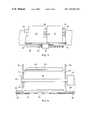
- FIG. 4is a view in longitudinal section illustrating the printing drum in the embodiment of FIG. 1 ;
- FIG. 5is a graphical illustration showing the effect of a long term variation of screw pitch for a lead screw
- FIG. 6is a graphical illustration showing the effect of a cyclical variation of screw pitch in a lead screw.
- FIG. 7is a perspective view showing a typical printhead of the type used in the embodiment shown in FIG. 1 ;
- FIG. 8is a schematic side view showing another embodiment of a printer arranged according to the invention.
- FIG. 9is a graphical illustration showing the Banderly curve representing the variation in the lower limit of visual detectability of adjacent bands in an image with respect to the spacing of the bands and density differences between the bands.
- FIG. 10is a graphical illustration showing the Hammerly curve which represents the lower limit of visual detectability of edge raggedness with respect to image pixel spacing.
- a printer 10includes a housing 12 enclosing a drum 14 which is supported for rotation in the direction indicated by the arrow 16 and a carriage 18 supporting a spaced pair of ink jet printheads 20 and 22 which are arranged to eject ink drops selectively onto a substrate sheet 24 carried by the drum 14 .
- the drum 14has an axial drive shaft 26 which is supported at opposite ends in bearings 28 in two support plates 30 which are rigidly supported on a base plate 32 .
- a drive motor 34is coupled to one end of the drum drive shaft 26 and also to a lead screw 36 which is supported at opposite ends in bearings 38 supported by brackets 39 ( FIG. 4 ) from the support plates 30 .
- both the drum drive shaft 26 and the lead screw 36are biased toward the right end of the support plate 30 , as seen in FIG. 2 , by spring washers (not shown.)
- the lead screw 36passes through a nut 40 affixed to the carriage 18 supporting the printheads 20 and 22 and the pitch of the lead screw 36 is selected so as to drive the carriage parallel to the drum axis by a predetermined distance during each rotation of the drum 14 .
- the lead screw 36is a KERK rolled lead screw designed for high accuracy of the thread pitch throughout its length and has a high stiffness and the nut 40 is a KERK ZBX plastic antibacklash nut.
- the drive shaft 26is coupled to an encoder 42 which encodes each position on the drum and thus generates a train of electrical pulses at a rate which is dependent on the rate of rotation of the drum 14 , such as 1000 pulses per drum rotation.
- the encoder signalsare supplied to a multiplier unit 43 , which preferably includes a phase-locked loop (PLL) multiplier and generates ink drop ejection actuation signals for the printheads 20 and 22 at an increased rate which is directly related to the encoder output signals and therefore to the speed of rotation of the drum 14 , for example, 13,000 pulses per drum rotation and supplies them to a control unit 44 though a line 46 .
- PLLphase-locked loop
- the necessary pulse rate for high resolution imagesis obtained without requiring a high resolution encoder, which is an order of magnitude more expensive than an encoder, such as a Hewlett-Packard HEDS 5540 encoder, producing 1000 pulses per revolution.
- Both the low resolution encoder 42 and the PLL multiplier unit 43together cost only a small fraction of the cost of a high resolution encoder producing, for example, 13,000 pulses per revolution.
- the encodermay also be used to control the drum speed during acceleration and deceleration as well as during continuous running when the output is supplied directly through a line 47 to the servocontroller (not shown) in the control unit 44 for the drum drive motor 34 , while the PLL multiplier 43 supplies high frequency pulses to control the drop ejection rate.
- a cumulative DC pitch errormay occur in the manufacture of a lead screw in the manner shown in FIG. 5 . This may amount to about one part in 500, i.e., about one millimeter over the length of a drum 50 cm long. For adjacent image segments produced by 40-orifice arrays which are about 1.7 mm. long the positioning error between adjacent drops resulting from DC pitch error is only about 0.003 mm, which is not visually detectable.
- Each of the printheads 20 and 22has the same structure, which is illustrated schematically in FIG. 7 for the printhead 20 .
- the printhead 20has four ink reservoirs 48 , 50 , 52 and 54 .
- Each reservoirsupplies a different ink for selective ejection from a corresponding array of 40 orifices in an orifice plate 56 which is mounted at the side of the printhead facing the substrate sheet 24 . Since there are 40 orifices in the array supplied by each reservoir, the orifice plate 56 contains a total of 160 orifices 58 in a straight line.
- the printhead 20includes a conventional piezoelectric drop ejection arrangement for each of the orifices 58 whereby ink supplied from a corresponding reservoir is selectively ejected through the orifice as a drop at the appropriate time in response to a signal received through a line 60 from the control unit 44 .
- each of the ink reservoirs 48 - 54 in the printhead 20is replenished periodically though a corresponding conduit in a flexible ink supply line 62 from one of series of corresponding remote stationary reservoirs 64 , 66 , 68 and 70 provided in the housing 12 .
- a similar set of stationary reservoirs 72 , 74 , 76 and 78is also connected through conduits in a supply line 63 to corresponding reservoirs in the printhead 22 and that printhead likewise receives signals from the line 60 to control the ejection of ink drops from the orifices therein.
- the stationary reservoirs 64 - 78are readily accessible to the operator of the system to permit replenishment of the ink as needed.
- the supply lines 62 and 63may also include a vacuum conduit by which subatomospheric pressure may be supplied to the printheads 20 and 22 for deaeration of the ink as described, for example, in the Hine et. al. U.S. Pat. No. 4,940,995, the disclosure of which is incorporated herein by reference.
- the stationary reservoirs 64 - 78are heated to a temperature above the melting point of the inks therein and each ink conduit in the lines 62 and 63 may include a heater wire in order to melt the ink in the conduit during refill of a printhead reservoir from the corresponding stationary reservoir as described, for example, in the Hoisington et. al. U.S. Pat. No. 4,814,786.
- digital signals representing the image information in terms of color and density of each pixelare supplied through an input line 82 to the control unit 44 .
- the control unitconverts these signals in a conventional manner to produce selective ink drop ejection actuation signals timed for operation of the piezoelectric actuators in the ink jet heads 20 and 22 at the appropriate times to eject ink drops of appropriate color and density for deposition at predetermined locations on the substrate sheet 24 as the drum 14 is rotated and the printheads 20 and 22 are advanced parallel to the axis of the drum by rotation of the lead screw 36 .
- This low density inkmay then be used to produce further reduced density images by printing fewer drops, as with the high density ink. Because the ink is low density, it may be possible to get past the minimum point on the Banderly curve without a grainy image. If not, a third, even less dense, ink may be employed, and if this produces a grainy image at some spot separation, then a fourth, lower density ink could be employed.
- the stationary reservoirs 64 , 66 , 68 and 70 connected to the printhead 20contain conventional, high-density black, magenta, cyan and yellow inks, respectively, which are, in turn, supplied to the onhead reservoirs, 48 , 50 , 52 and 54 in the printhead 20 for selective ejection from corresponding groups of 40 orifices 58 in the orifice plate 56 during the printing operation and three of the four stationary reservoirs 72 , 74 , 76 and 78 connected to the printhead 22 are supplied with low-density black, magenta and cyan inks, respectively.
- the inventiontakes advantage of the fact that the visual perception of density gradations of yellow ink is substantially less than that of cyan, magenta and black inks in order to enhance the quality of a color image without increasing the total number of inks required or the complexity of the printing system.
- the fourth reservoir connected to the printhead 22instead of providing low density yellow ink, is utilized for a special color, such as red or green, which might otherwise require a combination of the standard subtractive colors, or a specific hue which may be used frequently in the printing operation.
- the fourth reservoir of that setmay be supplied with black ink of even lower density than the black ink in the other reservoir in order to enhance the range of available densities.
- the four reservoirs connected to the printhead 20supply yellow ink and black inks of three different density levels and the four reservoirs connected to the printhead 22 supply cyan and magenta inks at two different density levels. This reduces the drop positioning errors in placing high and low density inks of the same color adjacent to each other.
- each ink drop applied to the substrate 24must be deposited at precisely the required position and, to accomplish this, any error in the location of the printhead orifices with respect to the required position must be kept below about 0.005 mm.
- the printhead 22must be positioned on the carriage so as to apply ink drops to exactly the same locations on the substrate sheet 24 as those to which drops may be applied from the printhead 20 , either in combination with drops from the printhead 20 or in place of drops from printhead 20 depending upon the selective activation signals supplied through the line 60 from the control unit 44 .
- the carriage 18includes, as schematically illustrated in FIG. 3 , an angular printhead adjustment 84 for adjusting the sabre angle of each of the printheads 20 and 22 and a lateral spacing adjustment 86 to adjust the axial spacing of the heads with respect to each other.
- the sabre angleis zero and the spacing between the last of the orifices 58 in the printhead 20 and the first of the orifices 58 in the printhead 22 is set at 64 image pixels. If a sabre angle other than zero is used, the control unit 44 should be programmed to time the drop ejection pulses to compensate for differing drop path lengths due to the curvature of the drum surface, taking the substrate motion into account.
- the printheads 20 and 22may be spaced in the circumferential direction of the drum rather than in the axial direction as shown schematically in FIG. 8 .
- the physical spacing between orifices in axially spaced printheadsmust be precisely equal to a unit number of image pixels, the spacing between orifices in angularly spaced printheads need not be equal to a unit number of pixels.
- timing of the pulses from the control unit 44may be used to compensate for variations in the relative positions of the orifices in the printheads 20 and 22 in the circumferential direction of the drum, regardless of whether the printheads are spaced axially or circumferentially.
- the carriage 18is supported on a rail 88 which is affixed near opposite ends on the support plates 30 so as to provide a predetermined spacing between the rail 88 and the drum drive shaft bearings 28 in the support plates 30 .
- the carriage 18is slidably supported on the carriage support rail 88 by three bearing pads 90 which engage the carriage support rail surfaces and have dimensions which provide predetermined, precisely controlled spacing between the rail 88 and the orifice plate 56 in each of the printheads 20 and 22 , the rail surfaces being spaced at a distance from the drum axis which is kept to within about 0.025 mm of the desired value.
- the support plates 30are welded to a torsionally stiff, rectangular steel tube 92 about three millimeters thick and having cross-sectional dimensions of about 3.75 cm by 7.75 cm.
- the drum 14consists of an aluminum cylinder 94 supported at opposite ends from the drive shaft 26 by thermally insulative glass-reinforced plastic end bells 96 .
- the outer drum surfaceis machined by drum rotation to provide the desired drum diameter, which in a preferred embodiment is approximately 16.4 cm, and to assure uniform spacing of the surface 98 of the drum from the axis of the drive shaft 26 .
- This machining of the assembled drumminimizes runout of the drum surface 98 to 0.1 mm, which is small enough to prevent visual detection of image errors resulting from drum surface runout.
- the spacing between the orifice plates 56 of the printheads mounted on the carriage 18 and the surface of the drum 14can be maintained within about 0.075 mm.
- a drum heater 100is mounted outside the drum closely adjacent to the drum surface 98 and is controlled by a temperature detector 102 which engages the surface 98 of the drum outside the image area.
- the thickness of the aluminum cylinder 94is preferably in the range of about 0.25 to 1.25 cm.
- the housing 12is provided with an internal partition 104 , containing entrance and exit openings for the sheets 24 , which defines a “hot zone” enclosing most of the printer components other than the control unit 44 and the power supply.
- a thermostatically controlled exhaust fan 106responsive to a temperature detector 108 mounted on one of the support plates 30 , which is representative of the ambient temperature within the hot zone, is arranged to exhaust air from the hot zone whenever the detected temperature exceeds a predetermined value.
- the drum heater 100has a circumferential dimension equal to about 30-45% of the drum circumference and an axial length approximately equal to that of the drum and the radial spacing of the heater from the drum is about 1-2 mm.
- the hot zone within the housing 12is maintained at a temperature no less than about 10° C. below of the desired temperature of the surface 98 , for example at about 35°-45° C.
- a supply of substrate material such as sheets of paper 24is maintained in a supply tray 110 which is received in the lower end of the rear wall of the housing 12 .
- Each sheet 24is selectively removed from the tray 110 as needed by a friction feed device 112 which advances the top sheet from the supply tray through an opening near the bottom of the partition 104 to a pair of feed rolls 114 .
- the sheet 24With the drum 14 in a stationary position, the sheet 24 is fed against the inclined surface of a baffle 116 which directs the sheet against the drum surface until it is received within a set of lead edge grippers 118 which are actuated in a conventional manner by internal cams (not shown) within the drum 14 so as to be raised away from the drum surface until the sheet 24 is properly positioned.
- the grippers 118are closed to clamp the lead edge of the sheet to the drum surface and the drum is rotated in the direction indicated by the arrow 16 and the sheet is held tightly against the drum by a roll 119 until a set of tail edge grippers 120 is in position to receive and clamp the trailing edge of the sheet 24 against the drum surface.
- the sheetIn order to assure good image quality the sheet must be held in intimate contact with the drum surface while the image is printed.
- the lead edge grippers 118are raised to release the lead edge of the sheet and a set of stripper rolls 121 and sheet strippers 122 , shown in FIG. 1 , are moved against the drum surface to strip the sheet 24 from the drum and direct it through an opening 123 near the top of the partition 104 .
- the stripper rolls 121which have a diameter of about 2.5 cm. and are urged with a low force of about 180 gm ⁇ cm of roll width, are made of resilient rubber or similar material having a low modulus i.e.
- a pair of outfeed drive rolls 124receive the sheet outside the opening 123 in the partition 104 and convey it to an output tray 126 , the trailing edge of the sheet 24 being released by the grippers 120 after the sheet has been captured by the outfeed rolls 124 . Since the outfeed rolls 124 are located outside the hot zone, the image on the sheet 24 has cooled sufficiently by the time it reaches them to prevent any disturbance of the image as it passes between them.
- the carriage 18On startup and periodically during operation of the printer, for example after every 20 or 30 prints have been made, the carriage 18 is automatically driven to the left end of the support rail 88 as seen FIG. 2 , where the printheads 20 and 22 are positioned adjacent to a maintenance station 128 .
- the orifice plates 56are cleaned by wiping with a web of paper as described, for example, in the Spehrley, Jr. et. al. U.S. Pat. No. 4,928,210, the disclosure of which is incorporated herein by reference.
- any necessary purging of the printheadsis carried out at the maintenance station in the manner described in that patent and in the Hine et. al. U.S. Pat. No. 4,937,598, the disclosure of which is also incorporated herein by reference.
- the supply lines 62 and 63may also include an air pressure conduit supplying air at elevated pressure to each printhead.
- the control unit 44transmits signals to the printheads which cause them to print images using an interlace technique.
- interlace arrangementink is ejected during each drum rotation from orifices 58 in each head which are spaced from each other rather than from adjacent orifices.
- Typical ink jet interlace techniquesare described, for example, in the Hoisington et. al. U.S. Pat. No. 5,075,689, the disclosure of which is incorporated herein by reference.
- the orifices which eject ink drops orifice in each color array in the printheads 20 and 22 during any scanare spaced by approximately 0.47 mm.
- thismay be accomplished in many ways.
- the orifices which are actuated during any given scan of a 40-orifice arraymay be spaced by eleven image pixels, which provides a resolution in the subscanning axial direction i.e., the direction parallel to the drum axis, of 232.3 dots/cm., or, for an array having 35 to 39 orifices, by thirteen image pixels which provides resolution in that direction of 274.4 dots/cm.
- the spacing between orifices activated during any scanmay be twelve image pixels, providing resolution of 253.5 dots/cm. and for a 39-orifice array, the orifices actuated during any scan may be spaced by fourteen image pixels, which provides subscanning direction resolution of 295.7 dots/cm. Certain of these arrangements may be more effective than others in avoiding visual effects of drop positioning errors.
- a substrate sheet having dimensions of about 35.5 cm. by 50 cm.can be accommodated and high-resolution multicolor continuous images about having a size as large as 35 cm. by 49 cm. can be printed.
- the imagescan be printed at a rate of about ten per hour.
- the resulting imagewill have a trapezoidal shape which is very slightly skewed from rectangular, by 1.7 mm in a height of 355 mm, which is not easily noticed. If desired, this can be corrected by appropriate programming of the control unit 44 to preconfigure the image by the same skewed amount in the opposite direction.
- the carriage 18may be indexed intermittently rather than continuously by a servomotor, which replaces the coupling between the lead screw and the drumdrive motor 34 .
- the servomotoris actuated to advance the printhead by a distance in pixels corresponding to the number of orifices in each color array by turning the lead screw preferably one revolution during the interval between the tail edge and the lead edge of the sheet 24 as the drum 14 rotates.
- the servometercan be controlled during printing directly from the encoder output through the line 47 and the carriage 18 can be returned at high speed after completing the printing of an image while the drum is stationary or turning at a low speed to permit loading and unloading of the sheets 24 on the drums.
Landscapes
- Engineering & Computer Science (AREA)
- Quality & Reliability (AREA)
- Ink Jet (AREA)
- Particle Formation And Scattering Control In Inkjet Printers (AREA)
Abstract
Description
Claims (47)
Priority Applications (7)
| Application Number | Priority Date | Filing Date | Title |
|---|---|---|---|
| US08/432,783US7237872B1 (en) | 1995-05-02 | 1995-05-02 | High resolution multicolor ink jet printer |
| PCT/US1996/006175WO1996034762A1 (en) | 1995-05-02 | 1996-05-02 | High resolution multicolor ink jet printer |
| DE69623058TDE69623058T2 (en) | 1995-05-02 | 1996-05-02 | High-resolution multi-color inkjet printer |
| EP96913907AEP0771274A4 (en) | 1995-05-02 | 1996-05-02 | High resolution multicolor ink jet printer |
| EP99202139AEP0949081B1 (en) | 1995-05-02 | 1996-05-02 | High resolution multicolor ink jet printer |
| JP53350296AJP3256546B2 (en) | 1995-05-02 | 1996-05-02 | High resolution multicolor inkjet printer |
| US11/765,890US7690779B2 (en) | 1995-05-02 | 2007-06-20 | High resolution multicolor ink jet printer |
Applications Claiming Priority (1)
| Application Number | Priority Date | Filing Date | Title |
|---|---|---|---|
| US08/432,783US7237872B1 (en) | 1995-05-02 | 1995-05-02 | High resolution multicolor ink jet printer |
Related Child Applications (1)
| Application Number | Title | Priority Date | Filing Date |
|---|---|---|---|
| US11/765,890ContinuationUS7690779B2 (en) | 1995-05-02 | 2007-06-20 | High resolution multicolor ink jet printer |
Publications (1)
| Publication Number | Publication Date |
|---|---|
| US7237872B1true US7237872B1 (en) | 2007-07-03 |
Family
ID=23717571
Family Applications (2)
| Application Number | Title | Priority Date | Filing Date |
|---|---|---|---|
| US08/432,783Expired - LifetimeUS7237872B1 (en) | 1995-05-02 | 1995-05-02 | High resolution multicolor ink jet printer |
| US11/765,890Expired - Fee RelatedUS7690779B2 (en) | 1995-05-02 | 2007-06-20 | High resolution multicolor ink jet printer |
Family Applications After (1)
| Application Number | Title | Priority Date | Filing Date |
|---|---|---|---|
| US11/765,890Expired - Fee RelatedUS7690779B2 (en) | 1995-05-02 | 2007-06-20 | High resolution multicolor ink jet printer |
Country Status (5)
| Country | Link |
|---|---|
| US (2) | US7237872B1 (en) |
| EP (2) | EP0771274A4 (en) |
| JP (1) | JP3256546B2 (en) |
| DE (1) | DE69623058T2 (en) |
| WO (1) | WO1996034762A1 (en) |
Cited By (5)
| Publication number | Priority date | Publication date | Assignee | Title |
|---|---|---|---|---|
| US20080018682A1 (en)* | 1995-05-02 | 2008-01-24 | Fujifilm Dimatix, Inc. | High Resolution Multicolor Ink Jet Printer |
| US20090309908A1 (en)* | 2008-03-14 | 2009-12-17 | Osman Basarah | Method for Producing Ultra-Small Drops |
| US20090322803A1 (en)* | 2008-06-25 | 2009-12-31 | Petar Nedeljkovic | Method and system for setting display resolution |
| US20100141973A1 (en)* | 2008-12-05 | 2010-06-10 | Alpha Technologies Inc. | High density, high intensity ink formulation and method for printing high intensity colors |
| CN103249568A (en)* | 2010-12-10 | 2013-08-14 | 柯尼卡美能达株式会社 | Inkjet recording device |
Families Citing this family (16)
| Publication number | Priority date | Publication date | Assignee | Title |
|---|---|---|---|---|
| WO1998026934A1 (en) | 1996-12-18 | 1998-06-25 | Kabushiki Kaisha Tec | Ink jet printer |
| DE69800703T2 (en) | 1998-11-16 | 2001-10-25 | Agfa-Gevaert N.V., Mortsel | Large format printer with a central conditioning unit for checking and monitoring the developer status |
| DE69917589T2 (en)* | 1999-03-31 | 2005-06-16 | Agfa-Gevaert | Improved color quality printing using multiple print stations for the same color |
| GB2379414A (en)* | 2001-09-10 | 2003-03-12 | Seiko Epson Corp | Method of forming a large flexible electronic display on a substrate using an inkjet head(s) disposed about a vacuum roller holding the substrate |
| WO2003029007A2 (en)* | 2001-10-04 | 2003-04-10 | E.I. Du Pont De Nemours And Company | Ink jet printing |
| US6811641B2 (en)* | 2001-12-12 | 2004-11-02 | Eastman Kodak Company | Lamination method to create a pre-press proof with a thermal mark |
| US7021735B2 (en) | 2003-03-28 | 2006-04-04 | Lexmark International, Inc. | Reduction of color plane alignment error in a drum printer |
| US7627343B2 (en)* | 2003-04-25 | 2009-12-01 | Apple Inc. | Media player system |
| US8001924B2 (en) | 2006-03-31 | 2011-08-23 | Asml Netherlands B.V. | Imprint lithography |
| US20100259589A1 (en)* | 2009-04-14 | 2010-10-14 | Jonathan Barry | Inert uv inkjet printing |
| US8567936B2 (en)* | 2010-11-10 | 2013-10-29 | Electronics For Imaging, Inc. | LED roll to roll drum printer systems, structures and methods |
| US8317298B2 (en) | 2010-11-18 | 2012-11-27 | Xerox Corporation | Inkjet ejector arrays aligned to a curved image receiving surface with ink recirculation |
| JP5605199B2 (en)* | 2010-12-10 | 2014-10-15 | コニカミノルタ株式会社 | Inkjet recording apparatus and inkjet recording method |
| JP5673055B2 (en)* | 2010-12-10 | 2015-02-18 | コニカミノルタ株式会社 | Inkjet recording device |
| US9527307B2 (en) | 2010-12-15 | 2016-12-27 | Electronics For Imaging, Inc. | Oxygen inhibition for print-head reliability |
| US9487010B2 (en) | 2010-12-15 | 2016-11-08 | Electronics For Imaging, Inc. | InkJet printer with controlled oxygen levels |
Citations (47)
| Publication number | Priority date | Publication date | Assignee | Title |
|---|---|---|---|---|
| US3008372A (en) | 1958-05-26 | 1961-11-14 | Servo Corp Of America | Code-wheel manufacturing apparatus |
| US3438057A (en) | 1966-12-30 | 1969-04-08 | Texas Instruments Inc | Photographic recorder using an array of solid state light emitters |
| US3512158A (en) | 1968-05-02 | 1970-05-12 | Bunker Ramo | Infra-red printer |
| GB1201624A (en) | 1967-11-14 | 1970-08-12 | Monotype Corp Ltd | Improvements in or relating to display apparatus |
| US3952311A (en) | 1972-04-24 | 1976-04-20 | The Laitram Corporation | Electro-optical printing system |
| US4009332A (en) | 1976-06-28 | 1977-02-22 | International Business Machines Corporation | Memory management system for an ink jet copier |
| JPS5616467A (en) | 1979-07-17 | 1981-02-17 | Bayer Ag | Manufacture of pyridinee44aldehydephenylhydrazone |
| JPS5644259A (en) | 1979-09-20 | 1981-04-23 | Canon Inc | Copying and recording device |
| JPS57178783A (en) | 1981-04-28 | 1982-11-04 | Canon Inc | Recorder |
| DE3122645A1 (en) | 1981-06-06 | 1982-12-23 | Olympia Werke Ag, 2940 Wilhelmshaven | Horizontal drive for a recording head |
| JPS5872461A (en) | 1981-10-26 | 1983-04-30 | Fujitsu Ltd | Ink jet recorder |
| US4401991A (en) | 1981-10-08 | 1983-08-30 | International Business Machines Corporation | Variable resolution, single array, interlace ink jet printer |
| DE3300447A1 (en) | 1983-01-08 | 1984-07-12 | Philips Patentverwaltung Gmbh, 2000 Hamburg | Rotary recording method |
| US4533923A (en)* | 1983-05-24 | 1985-08-06 | Canon Kabushiki Kaisha | Ink-jet recording method |
| US4538160A (en) | 1982-01-26 | 1985-08-27 | Minolta Camera Kabushiki Kaisha | Ink jet recording apparatus |
| JPS61108255A (en) | 1984-10-31 | 1986-05-26 | Canon Inc | Gradation recording method |
| US4672432A (en)* | 1983-04-28 | 1987-06-09 | Canon Kabushiki Kaisha | Method for recording a color image using dots of colorants of different densities |
| US4673951A (en)* | 1984-09-29 | 1987-06-16 | Minolta Camera Kabushiki Kaisha | Tone reproducible ink jet printer |
| JPS62180839A (en) | 1986-01-31 | 1987-08-08 | Ricoh Co Ltd | drum feeder |
| US4686538A (en) | 1984-10-31 | 1987-08-11 | Canon Kabushiki Kaisha | Tone recording method |
| JPS6321167A (en) | 1986-07-15 | 1988-01-28 | Ricoh Co Ltd | Rotary drum type ink jet recorder |
| US4751528A (en) | 1987-09-09 | 1988-06-14 | Spectra, Inc. | Platen arrangement for hot melt ink jet apparatus |
| JPS63183866A (en) | 1986-08-07 | 1988-07-29 | Nippon Seimitsu Kogyo Kk | Printing device |
| JPS63205241A (en) | 1987-02-20 | 1988-08-24 | Fujitsu Ltd | Hot melt inkjet recording device with fixing mechanism |
| JPS63288769A (en) | 1987-05-21 | 1988-11-25 | Nec Corp | Spacing mechanism |
| JPS6455248A (en) | 1987-08-26 | 1989-03-02 | Canon Kk | Ink jet recorder |
| JPH01228859A (en) | 1988-03-09 | 1989-09-12 | Toshiba Corp | Inkjet recording device |
| US4880324A (en)* | 1985-06-24 | 1989-11-14 | Canon Kabushiki Kaisha | Transfer method for heat-sensitive transfer recording |
| US4920355A (en)* | 1989-07-31 | 1990-04-24 | Eastman Kodak Company | Interlace method for scanning print head systems |
| US4959659A (en) | 1983-03-08 | 1990-09-25 | Canon Kabushiki Kaisha | Color picture forming apparatus and method |
| US4978971A (en) | 1989-11-06 | 1990-12-18 | Tektronix, Inc. | Method and apparatus for reformatting print data |
| JPH035161A (en) | 1989-06-01 | 1991-01-10 | Canon Inc | Image regeneration method and device therefor |
| JPH0356186A (en) | 1989-07-25 | 1991-03-11 | Japan Organo Co Ltd | Apparatus for removing dissolved carbon dioxide in liquid |
| US5043741A (en)* | 1988-06-03 | 1991-08-27 | Spectra, Inc. | Controlled ink drop spreading in hot melt ink jet printing |
| JPH04201263A (en) | 1990-11-29 | 1992-07-22 | S R Technos Kk | Registration adjusting device in ink jet printer |
| EP0497614A2 (en) | 1991-02-01 | 1992-08-05 | Tektronix Inc. | Method for high-speed interlaced printing along the axis of print head scanning |
| JPH0516367A (en) | 1991-07-09 | 1993-01-26 | Canon Inc | Image recorder |
| EP0540987A2 (en) | 1991-11-04 | 1993-05-12 | Hewlett-Packard Company | Wide-swath printer/plotter using multiple pen cartridges |
| EP0568272A1 (en) | 1992-05-01 | 1993-11-03 | Hewlett-Packard Company | Preheat roller for thermal ink-jet printer |
| EP0589669A1 (en) | 1992-09-24 | 1994-03-30 | Canon Kabushiki Kaisha | Recording apparatus and recording method |
| JPH06109096A (en) | 1992-06-29 | 1994-04-19 | Xerox Corp | Low-speed scanning stitch mechanism |
| JPH06115079A (en) | 1992-10-06 | 1994-04-26 | Canon Inc | Recording device |
| US5372852A (en)* | 1992-11-25 | 1994-12-13 | Tektronix, Inc. | Indirect printing process for applying selective phase change ink compositions to substrates |
| US5406392A (en)* | 1988-11-15 | 1995-04-11 | Canon Kabushiki Kaisha | Image recording apparatus using multiple recording of the same image information to obtain high resolution and tonality |
| US5485183A (en)* | 1993-06-30 | 1996-01-16 | Dataproducts Corporation | Interlaced dot-on-dot printing |
| US5568173A (en)* | 1993-09-07 | 1996-10-22 | Agfa-Gevaert, N.V. | Ink jet printing method |
| US5625397A (en)* | 1994-11-23 | 1997-04-29 | Iris Graphics, Inc. | Dot on dot ink jet printing using inks of differing densities |
Family Cites Families (36)
| Publication number | Priority date | Publication date | Assignee | Title |
|---|---|---|---|---|
| DE3326330C2 (en) | 1982-07-23 | 1994-06-09 | Canon Kk | Process for creating a grayscale image |
| JPS5970583A (en)* | 1982-10-15 | 1984-04-21 | Toray Ind Inc | Head-moving method of ink jet printer |
| JPS5970582A (en) | 1982-10-15 | 1984-04-21 | Toray Ind Inc | Cylindrical scanning type ink jet printer |
| US4525428A (en)* | 1983-01-25 | 1985-06-25 | Mitsubishi Paper Mills, Ltd. | Process for producing multicolor heat-transfer recording paper |
| US4574291A (en)* | 1984-08-29 | 1986-03-04 | Tektronix, Inc. | Phase locked synchronizer for printer timing control |
| JP2749814B2 (en) | 1987-03-23 | 1998-05-13 | キヤノン株式会社 | Inkjet recording method |
| US5140339A (en)* | 1987-03-23 | 1992-08-18 | Canon Kabushiki Kaisha | Ink jet recording with equal amounts of mono- and mixed color droplets |
| US4814786A (en) | 1987-04-28 | 1989-03-21 | Spectra, Inc. | Hot melt ink supply system |
| US4860026A (en)* | 1987-06-25 | 1989-08-22 | Canon Kabushiki Kaisha | Halftone image recording method using recording data having a plurality of concentrations for one color |
| US4873134A (en)* | 1988-08-10 | 1989-10-10 | Spectra, Inc. | Hot melt ink projection transparency |
| US5337079A (en)* | 1987-09-09 | 1994-08-09 | Spectra, Inc. | Post-processing of colored hot melt ink images |
| US5023111A (en)* | 1988-08-10 | 1991-06-11 | Spectra, Inc. | Treatment of hot melt ink images |
| JP2717798B2 (en) | 1988-05-13 | 1998-02-25 | キヤノン株式会社 | Inkjet recording method |
| US5105204A (en)* | 1988-06-03 | 1992-04-14 | Spectra, Inc. | Subtractive color hot melt ink reflection images on opaque substrates |
| US4971408A (en)* | 1988-11-15 | 1990-11-20 | Spectra, Inc. | Remelting of printed hot melt ink images |
| JPH0247075A (en)* | 1988-08-08 | 1990-02-16 | Minolta Camera Co Ltd | Recorder |
| US5114747A (en)* | 1988-08-10 | 1992-05-19 | Spectra, Inc. | Treatment of hot melt ink images |
| US4940995A (en) | 1988-11-18 | 1990-07-10 | Spectra, Inc. | Removal of dissolved gas from ink in an ink jet system |
| US4937598A (en) | 1989-03-06 | 1990-06-26 | Spectra, Inc. | Ink supply system for an ink jet head |
| JP3133750B2 (en)* | 1989-03-24 | 2001-02-13 | キヤノン株式会社 | Ink jet cartridge and ink jet recording apparatus using the same |
| JPH02286250A (en) | 1989-04-26 | 1990-11-26 | Seiko Epson Corp | inkjet printer |
| US5075689A (en) | 1989-05-31 | 1991-12-24 | Spectra, Inc. | Bidirectional hot melt ink jet printing |
| JPH03288674A (en) | 1990-04-05 | 1991-12-18 | Canon Inc | Recording apparatus |
| DE4021227A1 (en)* | 1990-07-04 | 1991-06-06 | Siemens Ag | DEVICE FOR DRYING RECORDING CARRIERS IN INK PRINTING DEVICES |
| JPH04140148A (en) | 1990-10-01 | 1992-05-14 | Canon Inc | Inkjet recording method |
| ATE221463T1 (en)* | 1993-02-05 | 2002-08-15 | Canon Kk | COLOR BEAM RECORDING DEVICE |
| JP2500583B2 (en) | 1993-03-17 | 1996-05-29 | 日本電気株式会社 | Image signal quantization characteristic control method and image signal compression coding apparatus |
| US5825377A (en)* | 1993-04-28 | 1998-10-20 | Canon Kabushiki Kaisha | Method and apparatus for ink-jet recording with inks having different densities |
| JP3236120B2 (en) | 1993-04-28 | 2001-12-10 | キヤノン株式会社 | Ink jet recording apparatus and ink jet recording method |
| JP3227268B2 (en)* | 1993-05-26 | 2001-11-12 | キヤノン株式会社 | Ink jet recording apparatus and ink jet recording method |
| JP3218851B2 (en) | 1994-03-29 | 2001-10-15 | ミノルタ株式会社 | Driving method of driving device using electro-mechanical conversion element |
| US5574078A (en)* | 1994-11-10 | 1996-11-12 | Lasermaster Corporation | Thermal compositions |
| US7237872B1 (en)* | 1995-05-02 | 2007-07-03 | Fujifilm Dimatrix, Inc. | High resolution multicolor ink jet printer |
| JP3288674B2 (en) | 1999-05-10 | 2002-06-04 | 佐伯 芳子 | Processed food with low moisture content and high calorie and excellent nutritional balance |
| JP4140148B2 (en) | 1999-11-04 | 2008-08-27 | 株式会社三洋物産 | Electric pachinko machine operation handle |
| JP4201263B2 (en) | 2003-10-27 | 2008-12-24 | 日本電信電話株式会社 | Intrusion detection system and recording medium |
- 1995
- 1995-05-02USUS08/432,783patent/US7237872B1/ennot_activeExpired - Lifetime
- 1996
- 1996-05-02EPEP96913907Apatent/EP0771274A4/ennot_activeWithdrawn
- 1996-05-02JPJP53350296Apatent/JP3256546B2/ennot_activeExpired - Lifetime
- 1996-05-02EPEP99202139Apatent/EP0949081B1/ennot_activeExpired - Lifetime
- 1996-05-02DEDE69623058Tpatent/DE69623058T2/ennot_activeExpired - Lifetime
- 1996-05-02WOPCT/US1996/006175patent/WO1996034762A1/ennot_activeApplication Discontinuation
- 2007
- 2007-06-20USUS11/765,890patent/US7690779B2/ennot_activeExpired - Fee Related
Patent Citations (52)
| Publication number | Priority date | Publication date | Assignee | Title |
|---|---|---|---|---|
| US3008372A (en) | 1958-05-26 | 1961-11-14 | Servo Corp Of America | Code-wheel manufacturing apparatus |
| US3438057A (en) | 1966-12-30 | 1969-04-08 | Texas Instruments Inc | Photographic recorder using an array of solid state light emitters |
| GB1201624A (en) | 1967-11-14 | 1970-08-12 | Monotype Corp Ltd | Improvements in or relating to display apparatus |
| US3512158A (en) | 1968-05-02 | 1970-05-12 | Bunker Ramo | Infra-red printer |
| US3952311B1 (en) | 1972-04-24 | 1990-03-27 | Laitram Corp | |
| US3952311A (en) | 1972-04-24 | 1976-04-20 | The Laitram Corporation | Electro-optical printing system |
| US4009332A (en) | 1976-06-28 | 1977-02-22 | International Business Machines Corporation | Memory management system for an ink jet copier |
| JPS5616467A (en) | 1979-07-17 | 1981-02-17 | Bayer Ag | Manufacture of pyridinee44aldehydephenylhydrazone |
| JPS5644259A (en) | 1979-09-20 | 1981-04-23 | Canon Inc | Copying and recording device |
| JPS57178783A (en) | 1981-04-28 | 1982-11-04 | Canon Inc | Recorder |
| DE3122645A1 (en) | 1981-06-06 | 1982-12-23 | Olympia Werke Ag, 2940 Wilhelmshaven | Horizontal drive for a recording head |
| US4401991A (en) | 1981-10-08 | 1983-08-30 | International Business Machines Corporation | Variable resolution, single array, interlace ink jet printer |
| JPS5872461A (en) | 1981-10-26 | 1983-04-30 | Fujitsu Ltd | Ink jet recorder |
| US4538160A (en) | 1982-01-26 | 1985-08-27 | Minolta Camera Kabushiki Kaisha | Ink jet recording apparatus |
| DE3300447A1 (en) | 1983-01-08 | 1984-07-12 | Philips Patentverwaltung Gmbh, 2000 Hamburg | Rotary recording method |
| US4959659A (en) | 1983-03-08 | 1990-09-25 | Canon Kabushiki Kaisha | Color picture forming apparatus and method |
| US4672432A (en)* | 1983-04-28 | 1987-06-09 | Canon Kabushiki Kaisha | Method for recording a color image using dots of colorants of different densities |
| US4533923A (en)* | 1983-05-24 | 1985-08-06 | Canon Kabushiki Kaisha | Ink-jet recording method |
| US4673951A (en)* | 1984-09-29 | 1987-06-16 | Minolta Camera Kabushiki Kaisha | Tone reproducible ink jet printer |
| JPS61108255A (en) | 1984-10-31 | 1986-05-26 | Canon Inc | Gradation recording method |
| US4686538A (en) | 1984-10-31 | 1987-08-11 | Canon Kabushiki Kaisha | Tone recording method |
| US4880324A (en)* | 1985-06-24 | 1989-11-14 | Canon Kabushiki Kaisha | Transfer method for heat-sensitive transfer recording |
| JPS62180839A (en) | 1986-01-31 | 1987-08-08 | Ricoh Co Ltd | drum feeder |
| JPS6321167A (en) | 1986-07-15 | 1988-01-28 | Ricoh Co Ltd | Rotary drum type ink jet recorder |
| JPS63183866A (en) | 1986-08-07 | 1988-07-29 | Nippon Seimitsu Kogyo Kk | Printing device |
| JPS63205241A (en) | 1987-02-20 | 1988-08-24 | Fujitsu Ltd | Hot melt inkjet recording device with fixing mechanism |
| JPS63288769A (en) | 1987-05-21 | 1988-11-25 | Nec Corp | Spacing mechanism |
| JPS6455248A (en) | 1987-08-26 | 1989-03-02 | Canon Kk | Ink jet recorder |
| US4751528A (en) | 1987-09-09 | 1988-06-14 | Spectra, Inc. | Platen arrangement for hot melt ink jet apparatus |
| US4751528B1 (en) | 1987-09-09 | 1991-10-29 | Spectra Inc | |
| JPH01228859A (en) | 1988-03-09 | 1989-09-12 | Toshiba Corp | Inkjet recording device |
| US5043741A (en)* | 1988-06-03 | 1991-08-27 | Spectra, Inc. | Controlled ink drop spreading in hot melt ink jet printing |
| US5406392A (en)* | 1988-11-15 | 1995-04-11 | Canon Kabushiki Kaisha | Image recording apparatus using multiple recording of the same image information to obtain high resolution and tonality |
| US5142374A (en)* | 1989-06-01 | 1992-08-25 | Canon Kabushiki Kaisha | Image recording method and apparatus therefor |
| JPH035161A (en) | 1989-06-01 | 1991-01-10 | Canon Inc | Image regeneration method and device therefor |
| JPH0356186A (en) | 1989-07-25 | 1991-03-11 | Japan Organo Co Ltd | Apparatus for removing dissolved carbon dioxide in liquid |
| US4920355A (en)* | 1989-07-31 | 1990-04-24 | Eastman Kodak Company | Interlace method for scanning print head systems |
| US4978971A (en) | 1989-11-06 | 1990-12-18 | Tektronix, Inc. | Method and apparatus for reformatting print data |
| JPH04201263A (en) | 1990-11-29 | 1992-07-22 | S R Technos Kk | Registration adjusting device in ink jet printer |
| US5450111A (en)* | 1990-11-29 | 1995-09-12 | Sr Technos Ltd. | Ink jet recording apparatus having drop-registration adjusting system |
| EP0497614A2 (en) | 1991-02-01 | 1992-08-05 | Tektronix Inc. | Method for high-speed interlaced printing along the axis of print head scanning |
| JPH0516367A (en) | 1991-07-09 | 1993-01-26 | Canon Inc | Image recorder |
| EP0540987A2 (en) | 1991-11-04 | 1993-05-12 | Hewlett-Packard Company | Wide-swath printer/plotter using multiple pen cartridges |
| EP0568272A1 (en) | 1992-05-01 | 1993-11-03 | Hewlett-Packard Company | Preheat roller for thermal ink-jet printer |
| JPH06109096A (en) | 1992-06-29 | 1994-04-19 | Xerox Corp | Low-speed scanning stitch mechanism |
| US5402156A (en) | 1992-06-29 | 1995-03-28 | Xerox Corporation | Slow scan stitching mechanism |
| EP0589669A1 (en) | 1992-09-24 | 1994-03-30 | Canon Kabushiki Kaisha | Recording apparatus and recording method |
| JPH06115079A (en) | 1992-10-06 | 1994-04-26 | Canon Inc | Recording device |
| US5372852A (en)* | 1992-11-25 | 1994-12-13 | Tektronix, Inc. | Indirect printing process for applying selective phase change ink compositions to substrates |
| US5485183A (en)* | 1993-06-30 | 1996-01-16 | Dataproducts Corporation | Interlaced dot-on-dot printing |
| US5568173A (en)* | 1993-09-07 | 1996-10-22 | Agfa-Gevaert, N.V. | Ink jet printing method |
| US5625397A (en)* | 1994-11-23 | 1997-04-29 | Iris Graphics, Inc. | Dot on dot ink jet printing using inks of differing densities |
Non-Patent Citations (5)
| Title |
|---|
| Patent Abstracts of Japan, vol. 008, No. 180 (M-318), Aug. 18, 1984 and JP 59 070583 A (Toray KK), Apr. 21, 1984. |
| Patent Abstracts of Japan, vol. 013, No. 100 (M-805), Mar. 9, 1989 & JP 63 288769 A (NEC Corp), Nov. 25, 1988. |
| Patent Abstracts of Japan, vol. 014, No. 209 (M-0968), Apr. 27, 1990 and JP 02 047075 A (Minolta Camera Co Ltd), Feb. 16, 1990. |
| Patents Abstracts of Japan, vol. 007, No. 024 (M-189), Jan. 29, 1983 & JP 57 178783 A (Cannon KK), Nov. 4, 1982. |
| Supplementary Partial European Search Report (EPO Form 1503) for Application No. EP 96 91 3907 dated Jun. 20, 1997. |
Cited By (12)
| Publication number | Priority date | Publication date | Assignee | Title |
|---|---|---|---|---|
| US20080018682A1 (en)* | 1995-05-02 | 2008-01-24 | Fujifilm Dimatix, Inc. | High Resolution Multicolor Ink Jet Printer |
| US7690779B2 (en) | 1995-05-02 | 2010-04-06 | Fujifilm Dimatix, Inc. | High resolution multicolor ink jet printer |
| US20090309908A1 (en)* | 2008-03-14 | 2009-12-17 | Osman Basarah | Method for Producing Ultra-Small Drops |
| US8186790B2 (en) | 2008-03-14 | 2012-05-29 | Purdue Research Foundation | Method for producing ultra-small drops |
| US20090322803A1 (en)* | 2008-06-25 | 2009-12-31 | Petar Nedeljkovic | Method and system for setting display resolution |
| US8441474B2 (en) | 2008-06-25 | 2013-05-14 | Aristocrat Technologies Australia Pty Limited | Method and system for setting display resolution |
| US20100141973A1 (en)* | 2008-12-05 | 2010-06-10 | Alpha Technologies Inc. | High density, high intensity ink formulation and method for printing high intensity colors |
| US8553281B2 (en) | 2008-12-05 | 2013-10-08 | Alpha Technologies Inc. | High density, high intensity ink formulation and method for printing high intensity colors |
| CN103249568A (en)* | 2010-12-10 | 2013-08-14 | 柯尼卡美能达株式会社 | Inkjet recording device |
| US8814347B2 (en) | 2010-12-10 | 2014-08-26 | Konica Minolta, Inc. | Inkjet recording device |
| CN103249568B (en)* | 2010-12-10 | 2015-05-06 | 柯尼卡美能达株式会社 | Inkjet recording device |
| EP2650132A4 (en)* | 2010-12-10 | 2017-10-18 | Konica Minolta, Inc. | Inkjet recording device |
Also Published As
| Publication number | Publication date |
|---|---|
| WO1996034762A1 (en) | 1996-11-07 |
| US7690779B2 (en) | 2010-04-06 |
| US20080018682A1 (en) | 2008-01-24 |
| JP3256546B2 (en) | 2002-02-12 |
| EP0771274A1 (en) | 1997-05-07 |
| EP0949081B1 (en) | 2002-08-14 |
| JPH09507806A (en) | 1997-08-12 |
| DE69623058T2 (en) | 2002-12-05 |
| DE69623058D1 (en) | 2002-09-19 |
| EP0949081A1 (en) | 1999-10-13 |
| EP0771274A4 (en) | 1998-02-11 |
Similar Documents
| Publication | Publication Date | Title |
|---|---|---|
| US7690779B2 (en) | High resolution multicolor ink jet printer | |
| EP0938973B1 (en) | Apparatus and method for automatically aligning print heads | |
| US6019466A (en) | Multicolor liquid ink printer and method for printing on plain paper | |
| US6893122B2 (en) | Image forming apparatus | |
| EP0748693B1 (en) | Thermal ink jet printhead with extended print capability | |
| US7959259B2 (en) | Inkjet printing apparatus and driving control method | |
| US8562098B2 (en) | Recording apparatus and recording method | |
| US7478893B2 (en) | Liquid ejection control method and liquid ejection apparatus | |
| US8376498B1 (en) | High productivity spreader/transfix system for duplex media sheets in an inkjet printer | |
| US4495507A (en) | Multicolor transfer heat-sensitive recording apparatus | |
| US6332665B1 (en) | Skewed substrate pixel array printing machine | |
| JPH032068A (en) | Registration correction device | |
| EP0881081B1 (en) | Serial thermal recording apparatus | |
| JP2001158135A (en) | Method and apparatus for printing color image with use of ink-jet printing head and thermosensitive type laser printing head | |
| JP3040455B2 (en) | Image forming device | |
| JP2786234B2 (en) | Ink jet recording apparatus and ink jet recording method | |
| JP2003305830A (en) | Recording device and recording method | |
| JPH02187355A (en) | Image recording device | |
| JPH03199052A (en) | copying device | |
| KR0132419B1 (en) | Video printer devices | |
| JP2004034472A (en) | Inkjet recording device | |
| JPH03189159A (en) | Ink jet recorder | |
| JP2000190535A (en) | Image recording apparatus | |
| GB2254048A (en) | Thermal printhead with plural lines of printing elements. | |
| JP2004142193A (en) | Recording device |
Legal Events
| Date | Code | Title | Description |
|---|---|---|---|
| AS | Assignment | Owner name:SPECTRA, INC., NEW HAMPSHIRE Free format text:ASSIGNMENT OF ASSIGNORS INTEREST;ASSIGNORS:SPEHRLEY, CHARLES W., JR.;HOISINGTON, PAUL A.;REEL/FRAME:007655/0874 Effective date:19950908 | |
| AS | Assignment | Owner name:SPECTRA, INC., NEW HAMPSHIRE Free format text:ASSIGNMENT OF ASSIGNORS INTEREST;ASSIGNOR:SPECTRA, INC.;REEL/FRAME:014210/0151 Effective date:19960531 | |
| AS | Assignment | Owner name:DIMATIX, INC., NEW HAMPSHIRE Free format text:CHANGE OF NAME;ASSIGNOR:SPECTRA, INC.;REEL/FRAME:016361/0929 Effective date:20050502 Owner name:DIMATIX, INC.,NEW HAMPSHIRE Free format text:CHANGE OF NAME;ASSIGNOR:SPECTRA, INC.;REEL/FRAME:016361/0929 Effective date:20050502 | |
| AS | Assignment | Owner name:FUJIFILM DIMATIX, INC., NEW HAMPSHIRE Free format text:CHANGE OF NAME;ASSIGNOR:DIMATIX, INC.;REEL/FRAME:018834/0595 Effective date:20060725 Owner name:FUJIFILM DIMATIX, INC.,NEW HAMPSHIRE Free format text:CHANGE OF NAME;ASSIGNOR:DIMATIX, INC.;REEL/FRAME:018834/0595 Effective date:20060725 | |
| STCF | Information on status: patent grant | Free format text:PATENTED CASE | |
| CC | Certificate of correction | ||
| CC | Certificate of correction | ||
| FPAY | Fee payment | Year of fee payment:4 | |
| FPAY | Fee payment | Year of fee payment:8 | |
| MAFP | Maintenance fee payment | Free format text:PAYMENT OF MAINTENANCE FEE, 12TH YEAR, LARGE ENTITY (ORIGINAL EVENT CODE: M1553); ENTITY STATUS OF PATENT OWNER: LARGE ENTITY Year of fee payment:12 |