US7236179B2 - Display device color channel reconstruction - Google Patents
Display device color channel reconstructionDownload PDFInfo
- Publication number
- US7236179B2 US7236179B2US10/695,545US69554503AUS7236179B2US 7236179 B2US7236179 B2US 7236179B2US 69554503 AUS69554503 AUS 69554503AUS 7236179 B2US7236179 B2US 7236179B2
- Authority
- US
- United States
- Prior art keywords
- display
- color
- spectrum
- channel
- light source
- Prior art date
- Legal status (The legal status is an assumption and is not a legal conclusion. Google has not performed a legal analysis and makes no representation as to the accuracy of the status listed.)
- Expired - Lifetime, expires
Links
Images


Classifications
- G—PHYSICS
- G09—EDUCATION; CRYPTOGRAPHY; DISPLAY; ADVERTISING; SEALS
- G09G—ARRANGEMENTS OR CIRCUITS FOR CONTROL OF INDICATING DEVICES USING STATIC MEANS TO PRESENT VARIABLE INFORMATION
- G09G5/00—Control arrangements or circuits for visual indicators common to cathode-ray tube indicators and other visual indicators
- G09G5/02—Control arrangements or circuits for visual indicators common to cathode-ray tube indicators and other visual indicators characterised by the way in which colour is displayed
- H—ELECTRICITY
- H04—ELECTRIC COMMUNICATION TECHNIQUE
- H04N—PICTORIAL COMMUNICATION, e.g. TELEVISION
- H04N1/00—Scanning, transmission or reproduction of documents or the like, e.g. facsimile transmission; Details thereof
- H04N1/46—Colour picture communication systems
- H04N1/56—Processing of colour picture signals
- H04N1/60—Colour correction or control
- H04N1/603—Colour correction or control controlled by characteristics of the picture signal generator or the picture reproducer
- H—ELECTRICITY
- H04—ELECTRIC COMMUNICATION TECHNIQUE
- H04N—PICTORIAL COMMUNICATION, e.g. TELEVISION
- H04N17/00—Diagnosis, testing or measuring for television systems or their details
- H04N17/04—Diagnosis, testing or measuring for television systems or their details for receivers
- H—ELECTRICITY
- H04—ELECTRIC COMMUNICATION TECHNIQUE
- H04N—PICTORIAL COMMUNICATION, e.g. TELEVISION
- H04N9/00—Details of colour television systems
- H04N9/12—Picture reproducers
- H04N9/31—Projection devices for colour picture display, e.g. using electronic spatial light modulators [ESLM]
- H04N9/3179—Video signal processing therefor
- H04N9/3182—Colour adjustment, e.g. white balance, shading or gamut
- G—PHYSICS
- G09—EDUCATION; CRYPTOGRAPHY; DISPLAY; ADVERTISING; SEALS
- G09G—ARRANGEMENTS OR CIRCUITS FOR CONTROL OF INDICATING DEVICES USING STATIC MEANS TO PRESENT VARIABLE INFORMATION
- G09G2320/00—Control of display operating conditions
- G09G2320/06—Adjustment of display parameters
- G09G2320/0693—Calibration of display systems
- H—ELECTRICITY
- H04—ELECTRIC COMMUNICATION TECHNIQUE
- H04N—PICTORIAL COMMUNICATION, e.g. TELEVISION
- H04N9/00—Details of colour television systems
- H04N9/12—Picture reproducers
- H04N9/30—Picture reproducers using solid-state colour display devices
- H—ELECTRICITY
- H04—ELECTRIC COMMUNICATION TECHNIQUE
- H04N—PICTORIAL COMMUNICATION, e.g. TELEVISION
- H04N9/00—Details of colour television systems
- H04N9/12—Picture reproducers
- H04N9/31—Projection devices for colour picture display, e.g. using electronic spatial light modulators [ESLM]
- H04N9/3102—Projection devices for colour picture display, e.g. using electronic spatial light modulators [ESLM] using two-dimensional electronic spatial light modulators
- H—ELECTRICITY
- H04—ELECTRIC COMMUNICATION TECHNIQUE
- H04N—PICTORIAL COMMUNICATION, e.g. TELEVISION
- H04N9/00—Details of colour television systems
- H04N9/64—Circuits for processing colour signals
- H04N9/73—Colour balance circuits, e.g. white balance circuits or colour temperature control
Definitions
- the inventionrelates to color imaging and, more particularly, to presentation of color images on display devices.
- Color display devicesare typically multi-channel devices in the sense that multiple physical color channels represent every pixel on the display.
- Multi-channel display devicesinclude cathode ray tubes (CRT), liquid crystal displays (LCD), plasma displays, and other imaging devices.
- CTRcathode ray tubes
- LCDliquid crystal displays
- plasma displaysand other imaging devices.
- One common example of a multi-channel deviceis a three channel device comprising red, green, and blue (RGB) channels.
- Each of the color channels in a multi-channel display devicemay be modeled as a combination of a light source and a light valve.
- the light sourcetypically comprises a common backlight and color filters for each of the channels.
- the light valvein the case of an LCD, comprises one or two fixed polarizers and liquid crystal cells (LCC), which rotate a polarization plane of passing light to regulate the amount of light emitted from the display.
- An emission spectrum for the light sourceis useful for spectral modeling and display calibration to improve color accuracy of imagery presented by the display.
- the light source emission spectrumis usually unknown, partially because the spectra of light sources vary between different manufacturers and models of display devices and from device to device.
- the emission spectrum for a light sourcemay change over time due to component aging, especially in the case of an LCD, which uses luminescent lamps as the common backlight.
- the inventionrelates to techniques for reconstructing color channels in a multi-channel display device.
- the inventionmay be particularly useful in reconstructing the light source spectra for the color channels of liquid crystal displays (LCD).
- LCDliquid crystal displays
- a light source spectrumcan be determined for each color channel of a display based on measured emission spectra for the color channels, an inverted contrast ratio for the display, and an assumed transmission spectrum for a light valve in the display.
- the inventionprovides techniques to compensate for light leakage from adjacent color channels with regard to wavelength dependent transmissions that cause hue shifts in images presented by the display device.
- the inventionis directed to a method comprising measuring a first emission spectrum of a display for a maximum display level, measuring a second emission spectrum of the display for a minimum display level, and measuring cumulative emission spectra for each of a plurality of color channels of the display with the respective color channel at a maximum level and the other channels at minimum levels.
- the methodfurther includes assuming a transmission spectrum for a light valve in the display operating at a maximum level, and determining an inverted contrast ratio based on the first emission spectrum measurement and the second emission spectrum measurement.
- a set of equationsis created for the color channels based on the measured cumulative emission spectra for the color channels, the measured inverted contrast ratio, and the assumed transmission spectrum. The equation set is then solved to determine a light source spectrum for each of the color channels.
- the inventionis directed to a system including a display, a plurality of color channels in the display, a light source and a light valve to model each of the color channels, and means for driving the light valve based on a color profile defined by light source spectra.
- the light source spectraare reconstructed from measured emission spectra for the color channels, an inverted contrast ratio for the display, and an assumed transmission spectrum for the light valve in the display.
- the inventionis directed to a method which determines a light source spectrum for each of a plurality of color channels of a display based on measured emission spectra for the color channels, an inverted contrast ratio for the display, and an assumed transmission spectrum for a light valve in the display.
- the inventionis directed to a computer-readable medium containing instructions.
- the instructionscause a programmable processor to receive cumulative emission spectrum measurements for each of a plurality of color channels of a display with the respective color channel at a maximum level and the other channels at minimum levels, assume a transmission spectrum for a light valve in the display operating at a maximum level, and determine an inverted contrast ratio for the display.
- the computer-readable mediumcontains further instructions that cause the programmable processor to solve a set of equations to determine a light source spectrum for each of the color channels based on the measured cumulative emission spectra for the color channels, the inverted contrast ratio, and the assumed transmission spectrum, and drive the light valve based on a color profile defined by the light source spectra.
- the inventionis directed to a method comprising measuring cumulative emission spectra for each of a plurality of color channels of a display with the respective color channel at a maximum level and the other channels at minimum levels, assuming a first transmission spectrum for a light valve in the display operating at a maximum level, and assuming a second transmission spectrum for the light valve in the display operating at a minimum level.
- the methodfurther comprises calculating an inverted contrast ratio based on the first transmission spectrum assumption and the second transmission spectrum assumption, creating a set of equations for the color channels based on the measured cumulative emission spectra for the color channels, the inverted contrast ratio, and the assumed first transmission spectrum, and solving the equations to determine a light source spectrum for each of the color channels.
- the inventionis capable of providing many advantages.
- the described embodimentscan improve color accuracy, and reduce color accuracy variation for images presented by different types and brands of display devices.
- display devicessuch as LCDs
- the light valve transmission spectrumis dependent on a wavelength and a digital driving signal.
- the described embodimentstake the wavelength dependency and its subsequent effects on the light source spectrum into account.
- the color channelscannot achieve a fully closed state, even when set at a minimum level, due to transmission spectrum wavelength dependency.
- the emission spectra measurements for each of the maximum level color channelsinclude light leakage from the minimum level, adjacent color channels.
- the light source emission spectra measurement accuracyimproves due to compensation of the excess light emission.
- Such compensationallows for the more accurate calibration of a display device color model and reduces non-physical effects in model calibration caused by contamination of the measurements by light leakage.
- the capability of reconstructing the light source spectraadds flexibility to color applications and allows for less dependency on particular types and brands of display devices to present imagery with consistent color quality.
- FIG. 1is a block diagram illustrating a color management system that makes use of color profiles formulated for a display device in accordance with the invention.
- FIG. 2is a block diagram illustrating a color profile generation system that generates a color profile based on a display device color model.
- FIG. 3is a block diagram illustrating a light source reconstruction system that reconstructs light source spectra based on display device spectral emission measurements.
- FIG. 4is a schematic diagram illustrating a color channel of a multi-channel liquid crystal display (LCD) device as a portion of the light source reconstruction system from FIG. 3 .
- LCDliquid crystal display
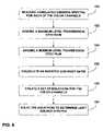
- FIG. 5is a flow diagram illustrating a method for reconstructing light source emission spectra for the multi-channel liquid crystal display.
- FIG. 6is a flow diagram illustrating another method for reconstructing light source emission spectra for the multi-channel liquid crystal display.
- FIG. 1is a block diagram illustrating a color management system 10 that makes use of color profiles formulated for a display device in accordance with the invention.
- the color profilesare built based on a display device color model that makes use of a light source spectrum reconstruction for a multi-channel color display device that takes into account light leakage from adjacent color channels and wavelength dependent transmissions.
- the wavelength dependencycauses hue shifts in the images reconstructed by the display device, as discussed in Reflective Liquid Crystal Displays by Wu S. and Yang D., John Wiley & Sons Ltd, p. 335, 2001.
- the color profiles used by color management system 10promote increased color image accuracy between images produced on different multi-channel color display devices.
- color management system 10includes a color management module 12 that generates a color map 18 between a source device 13 and a destination device 24 based on a source color profile 14 and a destination color profile 16 .
- Color map 18defines a conversion between source coordinates 20 associated with source device 13 and destination coordinates 22 associated with destination device 24 .
- Destination device 24may be a multi-channel color display devices including a liquid crystal display (LCD), a cathode ray tube (CRT) display, a plasma display, or the like.
- source device 13may be a scanner, a camera, or the like that acquires an image.
- An original image obtained by source device 13is color corrected by color management module 12 using color map 18 prior to being displayed via the destination display device 24 .
- a color management modulemay color correct an original image of a source device without generating a color map by using a combination of source and destination color profiles.
- Color management module 12may be realized by one or more software processes executing on a processor such as a desktop computer or workstation. Module 12 executes computer-readable instructions to support, at least in part, the functionality described herein. Color management module 12 facilitates color matching between destination device 24 and source device 13 .
- Source color profile 14specifies a set of color response characteristics associated with source device 13 .
- Destination color profile 16specifies a set of color response characteristics associated with destination device 24 .
- Source and destination color profiles 14 , 16permit reconciliation of color response differences between source device 13 and destination device 24 so that an image obtained by source device 13 can be accurately represented on destination display device 24 .
- Source and destination color profiles 14 , 16may generally conform to profiles specified by the International Color Consortium (ICC).
- Source coordinates 20specify color image values for an image in a device-dependent coordinate system associated with source device 13 , e.g., RGB in the event source device 13 is a scanner.
- Destination coordinates 22specify color image values for an image in a device-dependent coordinate system associated with destination device 24 .
- FIG. 2is a block diagram illustrating a color profile generation system 30 according to an embodiment of the invention.
- a profile generation module 40generates a color profile 42 based on data obtained from a display device, such as destination display device 24 of FIG. 1 .
- the data obtained from the display deviceinclude light source spectra 34 and device coordinates 36 , which are representative of the output characteristics of light sources and light valves, respectively, which form part of the display device.
- a device color model 32uses light source spectra 34 and device coordinates 36 to generate color coordinates 38 .
- Profile generation module 40builds color profile 42 based on the relationship between device coordinates 36 and color coordinates 38 . In the case illustrated in FIG.
- light source spectra 34are included to improve calibration accuracy of device color model 32 and therefore, improve accuracy of color coordinates 38 and color profile 42 .
- a device color modeldoes not input light source spectra and generates color coordinates based only on device coordinates, e.g. RGB.
- a color profileis built without a device color model; however, an accurate color profile would require a significant number of measurements. Building and calibrating a device color model reduces the number of measurements needed to build a color profile as no additional measurements are needed after the device color model is calibrated.
- the device color modelprovides a response similar to a display device, but generates device-independent color coordinates.
- Profile generation module 40sends device coordinates 36 to device color model 32 and receives a modeled response in the form of color coordinates 38 . Profile generation module 40 then creates color profile 42 that is capable of converting images from device-independent color coordinates to device specific coordinates. Profile generation module 40 may be configured to control device coordinates 36 , and therefore the light valves in the display device to obtain color coordinates 38 from device color model 32 , and generate color profile 42 based on the received data. As will be described, light source spectra 34 are calculated from equations based on measured and assumed spectral emissions of the display device.
- the display devicemay comprise any number of color channels, but for purposes of illustration, will be described herein as a three-channel display system with a red channel, a green channel, and a blue channel (RGB).
- Each pixel of an exemplary display devicesuch as an LCD, includes three color channels that combine to generate the color needed to accurately reproduce a pixel of an image.
- Each of the color channelsincludes one of the light sources and one of the light valves that may be manipulated to achieve the color specified for the pixel.
- the light source emission spectrum 34 S i ( ⁇ ) of the i th channelis a function of the wavelength, ⁇ , and determines the color of the channel.
- the light valve transmission spectrum ⁇ (d, ⁇ )is controlled by device coordinates 36 and may be assumed to be identical for every color channel.
- stationary polarizers and liquid crystal cells (LCC) with controllable phase retardationsconstitute the light valves.
- a voltage applied to the LCCis dependent upon the digital driving signal d and determines the phase retardation for passing light.
- the phase retardationcontrols rotation of a polarization plane of the light and therefore, the wavelength dependent intensity of light transmitted through the light valves.
- a cumulative emission spectrum for a pixelis a summation of all N individual color channels, in this case the red, green, and blue color channels.
- the light sourcesdetermine the color of light emitted for each of the color channels.
- the digital driving signal dcontrols the intensity of light transmitted by the light valves for each of the color channels.
- profile generation module 40generates color profile 42 for the LCD based on color coordinates 38 , which are determined by device color model 32 from light source spectra 34 and device coordinates 36 .
- the resulting color profile 42represents the color response characteristics of the LCD device.
- light source spectra 34must be determined from display measurements and calculations. The calculations compensate for adjacent channel leakage and light valve wavelength dependency that create inaccuracies in direct light source spectral measurements.
- the compensated light source spectra 34improve calibration of device color model 32 and therefore create a more accurate color profile 42 for the display device.
- Profile generation module 40may be realized by one or more software processes executing on a processor such as a desktop computer or workstation.
- FIG. 3is a block diagram illustrating a light source reconstruction system 50 that generates light source spectra 34 from display device spectral emission measurements.
- the spectral emission measurementsare from the three-channel LCD described above.
- System 50includes color channel emission spectra 54 , an assumed transmission spectrum 56 , a maximum emission spectrum 58 , and a minimum emission spectrum 60 input to a light source reconstruction module 52 .
- Light source reconstruction module 52makes use of an inverted contrast ratio 62 and an equation solver module 64 .
- Equation solver module 64generates light source spectra 34 based on color channel emission spectra 54 , assumed transmission spectrum 56 , and inverted contrast ratio 62 .
- light source spectra 34are determined by solving equations based on the measured color channel emission spectra 54 , assumed transmission spectrum 56 , and inverted contrast ratio 62 .
- the measured emission spectra of the display for the red, green, and blue channelsare included in color channel emission spectra 54 .
- Color channel emission spectra 54comprise cumulative emission measurements of each color channel with the respective color channel at a maximum level and the other channels at minimum levels.
- the red channel emission spectrumcomprises the cumulative emission measurement of the display when the red channel is at the maximum digital driving signal and the green channel and blue channel are at the minimum digital driving signal.
- the green channel and blue channel minimum level emissionscannot be assumed negligible, however, and can generate significant emission even when the pertinent light valves are turned “off.”
- the minimum level light valve transmission spectrum ⁇ (0, ⁇ )is still dependent on wavelength. Consequently, the light valves cannot fully close to block all light from being emitted.
- the assumed transmission spectrum 56is determined for the maximum digital driving signal, ⁇ (255, ⁇ ).
- the maximum digital driving signalrepresents an 8-bit system for purposes of example.
- the determinationmay be made by assuming the measured color channel emission spectra 54 constitute the light source spectra for the color channels, using default parameters for a particular type or brand of LCD, or squaring a cosine or sine function of phase retardation associated with the light valves.
- the main function of assumed transmission spectrum 56is to normalize the measured color channel emission spectra 54 and compensate for the wavelength dependency of the light valves.
- Inverted contrast ratio 62may be based on the maximum level transmission spectrum ⁇ (255, ⁇ ) and the minimum level transmission spectrum ⁇ (0, ⁇ ) for a given channel. Although both of the transmission spectrum values may be assumed, as described for assumed transmission spectrum 56 , the uncertainty of the rough approximations may introduce significant error in light source spectra 34 , which is perceived as a hue shift in color profile 42 . In the embodiment illustrated in FIG. 3 , a measured contrast ratio, ⁇ , is used in place of the assumed ratio. Maximum emission spectrum 58 of the display is measured for all of the color channels in the display at the maximum level, and minimum emission spectrum 60 is measured for all the color channels at the minimum level. As can be seen, the inverted ratio of emission spectrum measurements 58 and 60 is equivalent to the assumed transmission spectrum ratio.
- equations for the reconstruction of all channelsinclude only one assumed variable and produce a converging set of equations that can be solved by iteration. Accordingly, light source reconstruction module 52 applies the input values to equation solver module 64 .
- Equation solver module 64creates a light source emission equation for each of the color channels. For the case in which inverted contrast ratio 62 is based on the measured emission spectra for maximum and minimum display levels, as in equation (5), the light source spectrum equations may be expressed as:
- Equation solver module 64solves the light source spectrum equations, (6). Equation set (6) converges, which allows equation solver module 64 to solve the set by iterations. A high inverted contrast ratio 62 ensures that equation set (6) will converge.
- the outputs of equation solver module 64are reconstructed light source emission spectra 34 .
- Light source emission spectra 34include light source spectra for each of the color channels in the LCD device. The light source spectra 34 improve calibration accuracy of device color model 32 to accurately model the display device and generate color profile 42 , as shown in FIG. 2 .
- System 50improves the color accuracy of the multi-channel LCD by compensating light leakage contamination in light source spectral measurements.
- FIG. 4is a schematic diagram illustrating a color channel 80 of a typical liquid crystal display (LCD) device as a portion of light source reconstruction system 50 , from FIG. 3 .
- Color channel 80includes a light source 81 and a light valve 85 .
- Light source 81includes a backlight 82 and a color filter 84 .
- Light valve 85includes a first polarizer 86 , a second polarizer 88 , and liquid crystal cells (LCC) 90 disposed between the polarizers 86 and 88 .
- LCCliquid crystal cells
- Backlight 82emits light to every pixel, and therefore every color channel 80 .
- First polarizer 86 of light valve 85polarizes the passing light from backlight 82 .
- LCC 90rotates the polarization plane of the passing light.
- the amount of light transmitted by light valve 85depends on an orientation of the polarization plane of the passing light relative to second polarizer 88 .
- An angle of rotation of the polarization planedepends on a voltage or digital driving signal applied to LCC 90 and a wavelength of the light.
- Color filter 84filters the light transmitted by light valve 85 to define the color of channel 80 . In the case of the three-channel LCD described above, color filter 84 may be a red, green, or blue filter.
- Light source reconstruction system 50may improve the color accuracy of images displayed by the LCD.
- System 50uses display emission measurements to create and calibrate display device color model 32 , which is then used to create color profile 42 for the display.
- Color profile 42drives light valve 85 , e.g., from a host computer coupled to a destination display device, to generate a precise color output from color channel 80 and the LCD.
- Display device emissionmay vary between types and brands of displays.
- the color profile 42 built by color profile generation system 30 from FIG. 2may allow any LCD device to more accurately present the intended color of an image obtained by a source device.
- FIG. 5is a flow diagram illustrating a method for reconstructing light source emission spectra 34 for the multi-channel liquid crystal display described above.
- Light source reconstruction system 50 from FIG. 3reconstructs the light source spectra 34 to create and calibrate device color model 32 .
- Device color model 32may model the LCD and generate color coordinates 38 used to build color profile 42 for the LCD.
- Maximum emission spectrum 58is measured ( 100 ) for all color channels 80 set at a maximum level, which may also be considered an emission of white light.
- Minimum emission spectrum 60is then measured ( 102 ) for all of the color channels 80 set at a minimum level, which may be considered a black emission.
- Cumulative emission spectra 54are measured for each of the individual color channels 80 ( 104 ) with the respective channel at a maximum level and the other channels at minimum levels.
- transmission spectrum 56is assumed for the light valves 85 within the LCD operating at a maximum level ( 106 ). Assumed transmission spectrum 56 is known with accuracy between 5% and 20%. One of the assumption methods discussed in reference to FIG. 3 may be used to determine the assumption. Inverted contrast ratio 62 is determined ( 108 ) based on the maximum and minimum emission spectrum measurements 58 and 60 .
- the color channel emission spectra 54 , assumed transmission spectrum 56 , and measured inverted contrast ratio 62are used by equation solver module 64 in light source reconstruction module 52 to create a set of equations for light source emission spectra of the color channels 80 ( 110 ).
- the set of equationsis then solved by equation solver module 64 for each of the light source spectra 34 ( 112 ).
- FIG. 6is a flow diagram illustrating another method for reconstructing light source emission spectra 34 for the multi-channel liquid crystal display described above.
- Device color model 32uses the light source emission spectra 34 to model and calibrate the display.
- the cumulative emission spectrum 54is measured for each of the color channels 80 ( 120 ) with the respective channel at a maximum level and the other channels at minimum levels.
- Transmission spectraare assumed to be known for the light valves within the color channels 80 .
- Assumed transmission spectrum 56is assumed for one of the light valves operating at a maximum level ( 122 ).
- a minimum transmission spectrumis assumed for one of the light valve operating at a minimum level ( 124 ).
- the assumed transmission spectraare known with accuracy between 5% and 20%.
- One of the methods discussed in reference to FIG. 3may be used to determine the assumptions.
- the inverted contrast ratio 62is calculated ( 126 ) based on assumed maximum transmission spectrum 56 and the assumed minimum transmission spectrum.
- the assumed inverted contrast ratiocauses a larger hue shift to occur than the measured inverted contrast ratio used in the method illustrated in FIG. 5 .
Landscapes
- Engineering & Computer Science (AREA)
- Multimedia (AREA)
- Signal Processing (AREA)
- Physics & Mathematics (AREA)
- General Health & Medical Sciences (AREA)
- Biomedical Technology (AREA)
- Health & Medical Sciences (AREA)
- Computer Hardware Design (AREA)
- General Physics & Mathematics (AREA)
- Theoretical Computer Science (AREA)
- Control Of Indicators Other Than Cathode Ray Tubes (AREA)
- Liquid Crystal Display Device Control (AREA)
- Liquid Crystal (AREA)
- Spectrometry And Color Measurement (AREA)
Abstract
Description
Si(λ)=B(λ)*Fi(λ) (1)
The light valve transmission spectrum φ(d, λ) is controlled by device coordinates36 and may be assumed to be identical for every color channel. In a typical LCD device, stationary polarizers and liquid crystal cells (LCC) with controllable phase retardations constitute the light valves. A voltage applied to the LCC is dependent upon the digital driving signal d and determines the phase retardation for passing light. For polarized light, the phase retardation controls rotation of a polarization plane of the light and therefore, the wavelength dependent intensity of light transmitted through the light valves. An emission spectrum for an individual color channel i and for a given digital level d may be expressed as a product of the light source emission spectrum Si(λ) and the light valve transmission spectrum φ(d,λ) as follows:
Ei(d,λ)=Si(λ)*φ(d,λ) (2)
A cumulative emission spectrum for a pixel is a summation of all N individual color channels, in this case the red, green, and blue color channels.
The light sources determine the color of light emitted for each of the color channels. The digital driving signal d controls the intensity of light transmitted by the light valves for each of the color channels.
Ê(255,0,0,λ)=Sr(λ)*φ(255,λ)+Sg(λ)*φ(0,λ)+Sb(λ)*φ(0,λ)
{circumflex over (E)}(0,255,0,λ)=Sr(λ)*φ(0,λ)+Sg(λ)*φ(255,λ)+Sb(λ)*φ(0,λ) (4)
Ê(0,0,255,λ)=Sr(λ)*φ(0,λ)+Sg(λ)*φ(0,λ)+Sb(λ)*φ(255,λ)
where E is emission, S is the spectral contribution of light source, and φ(255,λ) is the digital driving value for a given light valve. The assumed
The first members of equations (6) are normalized on the assumed maximum
Claims (32)
Priority Applications (3)
| Application Number | Priority Date | Filing Date | Title |
|---|---|---|---|
| US10/695,545US7236179B2 (en) | 2003-10-28 | 2003-10-28 | Display device color channel reconstruction |
| EP04024914.6AEP1528792B1 (en) | 2003-10-28 | 2004-10-20 | Display device color channel reconstruction |
| JP2004314443AJP4571479B2 (en) | 2003-10-28 | 2004-10-28 | Color channel reconstruction method for display device |
Applications Claiming Priority (1)
| Application Number | Priority Date | Filing Date | Title |
|---|---|---|---|
| US10/695,545US7236179B2 (en) | 2003-10-28 | 2003-10-28 | Display device color channel reconstruction |
Publications (2)
| Publication Number | Publication Date |
|---|---|
| US20050088389A1 US20050088389A1 (en) | 2005-04-28 |
| US7236179B2true US7236179B2 (en) | 2007-06-26 |
Family
ID=34423355
Family Applications (1)
| Application Number | Title | Priority Date | Filing Date |
|---|---|---|---|
| US10/695,545Expired - LifetimeUS7236179B2 (en) | 2003-10-28 | 2003-10-28 | Display device color channel reconstruction |
Country Status (3)
| Country | Link |
|---|---|
| US (1) | US7236179B2 (en) |
| EP (1) | EP1528792B1 (en) |
| JP (1) | JP4571479B2 (en) |
Cited By (1)
| Publication number | Priority date | Publication date | Assignee | Title |
|---|---|---|---|---|
| WO2022051911A1 (en)* | 2020-09-08 | 2022-03-17 | 深圳市海谱纳米光学科技有限公司 | Method and device for restoring and reconstructing light source spectrum from hyperspectral image |
Families Citing this family (4)
| Publication number | Priority date | Publication date | Assignee | Title |
|---|---|---|---|---|
| US8878766B2 (en)* | 2007-11-15 | 2014-11-04 | Cree, Inc. | Apparatus and methods for selecting light emitters for a transmissive display |
| US8395638B2 (en)* | 2007-11-29 | 2013-03-12 | Datacolor Holding Ag | Method and apparatus for calibrating a display-coupled color measuring device |
| US8717567B2 (en)* | 2011-08-31 | 2014-05-06 | Datacolor Holding Ag | Method and apparatus for calibrating a color measurement device |
| CN104849220B (en)* | 2015-06-09 | 2017-06-27 | 武汉大学 | A Method for Obtaining Spectral Images of Planar Cultural Relics |
Citations (4)
| Publication number | Priority date | Publication date | Assignee | Title |
|---|---|---|---|---|
| EP0539943A1 (en) | 1991-10-31 | 1993-05-05 | Eastman Kodak Company | A method and apparatus for automatically calibrating a CRT display |
| US20030147085A1 (en)* | 2002-02-07 | 2003-08-07 | Leica Microsystems Jena Gmbh | Method for the determination of layer thicknesses |
| US6611249B1 (en) | 1998-07-22 | 2003-08-26 | Silicon Graphics, Inc. | System and method for providing a wide aspect ratio flat panel display monitor independent white-balance adjustment and gamma correction capabilities |
| US6712993B2 (en)* | 2001-04-27 | 2004-03-30 | Kasei Optonix, Ltd. | Phosphor and its production process |
Family Cites Families (6)
| Publication number | Priority date | Publication date | Assignee | Title |
|---|---|---|---|---|
| JPH01319734A (en)* | 1988-06-21 | 1989-12-26 | Seiko Instr Inc | Transmission type optical writing liquid crystal light valve |
| JP3277109B2 (en)* | 1995-03-22 | 2002-04-22 | シャープ株式会社 | Image display device |
| JPH09113898A (en)* | 1995-10-20 | 1997-05-02 | Toshiba Corp | LCD display |
| JP4050802B2 (en)* | 1996-08-02 | 2008-02-20 | シチズン電子株式会社 | Color display device |
| US6992803B2 (en)* | 2001-05-08 | 2006-01-31 | Koninklijke Philips Electronics N.V. | RGB primary color point identification system and method |
| JP3878030B2 (en)* | 2002-02-22 | 2007-02-07 | 富士通株式会社 | Image display device and image display method |
- 2003
- 2003-10-28USUS10/695,545patent/US7236179B2/ennot_activeExpired - Lifetime
- 2004
- 2004-10-20EPEP04024914.6Apatent/EP1528792B1/ennot_activeExpired - Lifetime
- 2004-10-28JPJP2004314443Apatent/JP4571479B2/ennot_activeExpired - Fee Related
Patent Citations (4)
| Publication number | Priority date | Publication date | Assignee | Title |
|---|---|---|---|---|
| EP0539943A1 (en) | 1991-10-31 | 1993-05-05 | Eastman Kodak Company | A method and apparatus for automatically calibrating a CRT display |
| US6611249B1 (en) | 1998-07-22 | 2003-08-26 | Silicon Graphics, Inc. | System and method for providing a wide aspect ratio flat panel display monitor independent white-balance adjustment and gamma correction capabilities |
| US6712993B2 (en)* | 2001-04-27 | 2004-03-30 | Kasei Optonix, Ltd. | Phosphor and its production process |
| US20030147085A1 (en)* | 2002-02-07 | 2003-08-07 | Leica Microsystems Jena Gmbh | Method for the determination of layer thicknesses |
Non-Patent Citations (5)
| Title |
|---|
| Berns, Roy S., et al. "Estimating Black-Level Emissions of Computer-Controlled Displays," Wiley Periodicals, Inc., vol. 28, No. 5, Oct. 2003. |
| European Search Report from EP Application No. 04024913.8-2217, dated Feb. 28, 2005, 5 pgs. |
| U.S. Appl. No. 10/695,035, entitled "Display Device Light Leakage Compensation," filed Oct. 28, 2003, by Arkady Ten. |
| Wu, S. and Yang, D., Reflective Liquid Crystal Displays. John Wiley & Sons Ltd., p. 35-37, 2001. |
| Yasuhiro Yoshida and Yoichi Yamamoto, "Color Management of Liquid Crystal Display Placed under Light Environment," XP-001144212, Electronics and Communications in Japan, Part 3, vol. 86, No. 7, 2003, 14 pgs. |
Cited By (2)
| Publication number | Priority date | Publication date | Assignee | Title |
|---|---|---|---|---|
| WO2022051911A1 (en)* | 2020-09-08 | 2022-03-17 | 深圳市海谱纳米光学科技有限公司 | Method and device for restoring and reconstructing light source spectrum from hyperspectral image |
| US11788888B2 (en) | 2020-09-08 | 2023-10-17 | Shenzhen Hypernano Optics Technology Co., Ltd | Method and device for restoring and reconstructing a spectrum of a light source based on a hyperspectral image |
Also Published As
| Publication number | Publication date |
|---|---|
| EP1528792B1 (en) | 2013-07-03 |
| US20050088389A1 (en) | 2005-04-28 |
| EP1528792A2 (en) | 2005-05-04 |
| EP1528792A3 (en) | 2009-08-05 |
| JP2005164578A (en) | 2005-06-23 |
| JP4571479B2 (en) | 2010-10-27 |
Similar Documents
| Publication | Publication Date | Title |
|---|---|---|
| KR100787215B1 (en) | Display characteristic calibration method, display characteristic calibration device, and computer program | |
| CN1323373C (en) | Projection plane color correction method and system for projector | |
| US10679544B2 (en) | Digital image processing chain and processing blocks and a display including the same | |
| US7218358B2 (en) | Method and apparatus for calibrating color temperature of color display devices | |
| US7113152B2 (en) | Device, system and method for electronic true color display | |
| US20070152949A1 (en) | Luminance control method, liquid crystal display device and computer program | |
| US8098932B2 (en) | Color correction method and apparatus of display apparatus | |
| US20120013635A1 (en) | Accurate Color Display Device | |
| US20070091055A1 (en) | Aging compensation method for liquid crystal display device, aging compensation apparatus for liquid crystal display device, computer program, and liquid crystal display device | |
| US20060071940A1 (en) | Correction data setting method and manufacturing method of image display apparatus | |
| US20110134332A1 (en) | Camera-Based Color Correction Of Display Devices | |
| US7561167B2 (en) | Image processing apparatus and image processing method | |
| Stone | Color balancing experimental projection displays | |
| JP6238757B2 (en) | White balance adjustment method, white balance adjustment device and display device | |
| US9437160B2 (en) | System and method for automatic color matching in a multi display system using sensor feedback control | |
| US20070024529A1 (en) | Device, system and method for electronic true color display | |
| US7057624B2 (en) | Display device light leakage compensation | |
| US7236179B2 (en) | Display device color channel reconstruction | |
| US11200828B2 (en) | Method for matching color temperature of display and system thereof | |
| US8334883B2 (en) | Rendering multispectral images on reflective displays | |
| US20060071937A1 (en) | Color characterization of projectors | |
| Seime et al. | Colorimetric characterization of LCD and DLP projection displays | |
| Bergquist | Fast and accurate colour gamut volume measurements of RGB displays with degenerate colours | |
| CN116896620A (en) | System and method for determining color mixing on a three-color display device having low brightness or illumination | |
| CN116684563B (en) | Light quality correction method and system for image display and image display method and system |
Legal Events
| Date | Code | Title | Description |
|---|---|---|---|
| AS | Assignment | Owner name:KODAK POLYCHROME GRAPHICS, LLC, CONNECTICUT Free format text:ASSIGNMENT OF ASSIGNORS INTEREST;ASSIGNOR:TEN, ARKADY;REEL/FRAME:014651/0848 Effective date:20031028 | |
| AS | Assignment | Owner name:EASTMAN KODAK COMPANY,NEW YORK Free format text:MERGER;ASSIGNOR:KPG HOLDING COMPANY INC. (FORMERLY KODAK POLYCHROME GRAPHICS LLC);REEL/FRAME:018096/0117 Effective date:20060619 Owner name:EASTMAN KODAK COMPANY, NEW YORK Free format text:MERGER;ASSIGNOR:KPG HOLDING COMPANY INC. (FORMERLY KODAK POLYCHROME GRAPHICS LLC);REEL/FRAME:018096/0117 Effective date:20060619 | |
| FEPP | Fee payment procedure | Free format text:PAYOR NUMBER ASSIGNED (ORIGINAL EVENT CODE: ASPN); ENTITY STATUS OF PATENT OWNER: LARGE ENTITY | |
| STCF | Information on status: patent grant | Free format text:PATENTED CASE | |
| FPAY | Fee payment | Year of fee payment:4 | |
| AS | Assignment | Owner name:CITICORP NORTH AMERICA, INC., AS AGENT, NEW YORK Free format text:SECURITY INTEREST;ASSIGNORS:EASTMAN KODAK COMPANY;PAKON, INC.;REEL/FRAME:028201/0420 Effective date:20120215 | |
| AS | Assignment | Owner name:WILMINGTON TRUST, NATIONAL ASSOCIATION, AS AGENT, Free format text:PATENT SECURITY AGREEMENT;ASSIGNORS:EASTMAN KODAK COMPANY;PAKON, INC.;REEL/FRAME:030122/0235 Effective date:20130322 Owner name:WILMINGTON TRUST, NATIONAL ASSOCIATION, AS AGENT, MINNESOTA Free format text:PATENT SECURITY AGREEMENT;ASSIGNORS:EASTMAN KODAK COMPANY;PAKON, INC.;REEL/FRAME:030122/0235 Effective date:20130322 | |
| AS | Assignment | Owner name:JPMORGAN CHASE BANK, N.A., AS ADMINISTRATIVE, DELAWARE Free format text:INTELLECTUAL PROPERTY SECURITY AGREEMENT (FIRST LIEN);ASSIGNORS:EASTMAN KODAK COMPANY;FAR EAST DEVELOPMENT LTD.;FPC INC.;AND OTHERS;REEL/FRAME:031158/0001 Effective date:20130903 Owner name:BARCLAYS BANK PLC, AS ADMINISTRATIVE AGENT, NEW YORK Free format text:INTELLECTUAL PROPERTY SECURITY AGREEMENT (SECOND LIEN);ASSIGNORS:EASTMAN KODAK COMPANY;FAR EAST DEVELOPMENT LTD.;FPC INC.;AND OTHERS;REEL/FRAME:031159/0001 Effective date:20130903 Owner name:JPMORGAN CHASE BANK, N.A., AS ADMINISTRATIVE, DELA Free format text:INTELLECTUAL PROPERTY SECURITY AGREEMENT (FIRST LIEN);ASSIGNORS:EASTMAN KODAK COMPANY;FAR EAST DEVELOPMENT LTD.;FPC INC.;AND OTHERS;REEL/FRAME:031158/0001 Effective date:20130903 Owner name:PAKON, INC., NEW YORK Free format text:RELEASE OF SECURITY INTEREST IN PATENTS;ASSIGNORS:CITICORP NORTH AMERICA, INC., AS SENIOR DIP AGENT;WILMINGTON TRUST, NATIONAL ASSOCIATION, AS JUNIOR DIP AGENT;REEL/FRAME:031157/0451 Effective date:20130903 Owner name:EASTMAN KODAK COMPANY, NEW YORK Free format text:RELEASE OF SECURITY INTEREST IN PATENTS;ASSIGNORS:CITICORP NORTH AMERICA, INC., AS SENIOR DIP AGENT;WILMINGTON TRUST, NATIONAL ASSOCIATION, AS JUNIOR DIP AGENT;REEL/FRAME:031157/0451 Effective date:20130903 Owner name:BARCLAYS BANK PLC, AS ADMINISTRATIVE AGENT, NEW YO Free format text:INTELLECTUAL PROPERTY SECURITY AGREEMENT (SECOND LIEN);ASSIGNORS:EASTMAN KODAK COMPANY;FAR EAST DEVELOPMENT LTD.;FPC INC.;AND OTHERS;REEL/FRAME:031159/0001 Effective date:20130903 Owner name:BANK OF AMERICA N.A., AS AGENT, MASSACHUSETTS Free format text:INTELLECTUAL PROPERTY SECURITY AGREEMENT (ABL);ASSIGNORS:EASTMAN KODAK COMPANY;FAR EAST DEVELOPMENT LTD.;FPC INC.;AND OTHERS;REEL/FRAME:031162/0117 Effective date:20130903 | |
| FPAY | Fee payment | Year of fee payment:8 | |
| MAFP | Maintenance fee payment | Free format text:PAYMENT OF MAINTENANCE FEE, 12TH YEAR, LARGE ENTITY (ORIGINAL EVENT CODE: M1553); ENTITY STATUS OF PATENT OWNER: LARGE ENTITY Year of fee payment:12 | |
| AS | Assignment | Owner name:QUALEX, INC., NEW YORK Free format text:RELEASE BY SECURED PARTY;ASSIGNOR:JP MORGAN CHASE BANK, N.A., AS ADMINISTRATIVE AGENT;REEL/FRAME:049814/0001 Effective date:20190617 Owner name:KODAK IMAGING NETWORK, INC., NEW YORK Free format text:RELEASE BY SECURED PARTY;ASSIGNOR:JP MORGAN CHASE BANK, N.A., AS ADMINISTRATIVE AGENT;REEL/FRAME:049814/0001 Effective date:20190617 Owner name:KODAK PORTUGUESA LIMITED, NEW YORK Free format text:RELEASE BY SECURED PARTY;ASSIGNOR:JP MORGAN CHASE BANK, N.A., AS ADMINISTRATIVE AGENT;REEL/FRAME:049814/0001 Effective date:20190617 Owner name:PAKON, INC., NEW YORK Free format text:RELEASE BY SECURED PARTY;ASSIGNOR:JP MORGAN CHASE BANK, N.A., AS ADMINISTRATIVE AGENT;REEL/FRAME:049814/0001 Effective date:20190617 Owner name:KODAK PHILIPPINES, LTD., NEW YORK Free format text:RELEASE BY SECURED PARTY;ASSIGNOR:JP MORGAN CHASE BANK, N.A., AS ADMINISTRATIVE AGENT;REEL/FRAME:049814/0001 Effective date:20190617 Owner name:EASTMAN KODAK COMPANY, NEW YORK Free format text:RELEASE BY SECURED PARTY;ASSIGNOR:JP MORGAN CHASE BANK, N.A., AS ADMINISTRATIVE AGENT;REEL/FRAME:049814/0001 Effective date:20190617 Owner name:KODAK AVIATION LEASING LLC, NEW YORK Free format text:RELEASE BY SECURED PARTY;ASSIGNOR:JP MORGAN CHASE BANK, N.A., AS ADMINISTRATIVE AGENT;REEL/FRAME:049814/0001 Effective date:20190617 Owner name:KODAK AMERICAS, LTD., NEW YORK Free format text:RELEASE BY SECURED PARTY;ASSIGNOR:JP MORGAN CHASE BANK, N.A., AS ADMINISTRATIVE AGENT;REEL/FRAME:049814/0001 Effective date:20190617 Owner name:KODAK REALTY, INC., NEW YORK Free format text:RELEASE BY SECURED PARTY;ASSIGNOR:JP MORGAN CHASE BANK, N.A., AS ADMINISTRATIVE AGENT;REEL/FRAME:049814/0001 Effective date:20190617 Owner name:NPEC, INC., NEW YORK Free format text:RELEASE BY SECURED PARTY;ASSIGNOR:JP MORGAN CHASE BANK, N.A., AS ADMINISTRATIVE AGENT;REEL/FRAME:049814/0001 Effective date:20190617 Owner name:FAR EAST DEVELOPMENT LTD., NEW YORK Free format text:RELEASE BY SECURED PARTY;ASSIGNOR:JP MORGAN CHASE BANK, N.A., AS ADMINISTRATIVE AGENT;REEL/FRAME:049814/0001 Effective date:20190617 Owner name:CREO MANUFACTURING AMERICA LLC, NEW YORK Free format text:RELEASE BY SECURED PARTY;ASSIGNOR:JP MORGAN CHASE BANK, N.A., AS ADMINISTRATIVE AGENT;REEL/FRAME:049814/0001 Effective date:20190617 Owner name:FPC, INC., NEW YORK Free format text:RELEASE BY SECURED PARTY;ASSIGNOR:JP MORGAN CHASE BANK, N.A., AS ADMINISTRATIVE AGENT;REEL/FRAME:049814/0001 Effective date:20190617 Owner name:LASER PACIFIC MEDIA CORPORATION, NEW YORK Free format text:RELEASE BY SECURED PARTY;ASSIGNOR:JP MORGAN CHASE BANK, N.A., AS ADMINISTRATIVE AGENT;REEL/FRAME:049814/0001 Effective date:20190617 Owner name:KODAK (NEAR EAST), INC., NEW YORK Free format text:RELEASE BY SECURED PARTY;ASSIGNOR:JP MORGAN CHASE BANK, N.A., AS ADMINISTRATIVE AGENT;REEL/FRAME:049814/0001 Effective date:20190617 | |
| AS | Assignment | Owner name:LASER PACIFIC MEDIA CORPORATION, NEW YORK Free format text:RELEASE BY SECURED PARTY;ASSIGNOR:BARCLAYS BANK PLC;REEL/FRAME:052773/0001 Effective date:20170202 Owner name:FPC INC., NEW YORK Free format text:RELEASE BY SECURED PARTY;ASSIGNOR:BARCLAYS BANK PLC;REEL/FRAME:052773/0001 Effective date:20170202 Owner name:KODAK PHILIPPINES LTD., NEW YORK Free format text:RELEASE BY SECURED PARTY;ASSIGNOR:BARCLAYS BANK PLC;REEL/FRAME:052773/0001 Effective date:20170202 Owner name:QUALEX INC., NEW YORK Free format text:RELEASE BY SECURED PARTY;ASSIGNOR:BARCLAYS BANK PLC;REEL/FRAME:052773/0001 Effective date:20170202 Owner name:NPEC INC., NEW YORK Free format text:RELEASE BY SECURED PARTY;ASSIGNOR:BARCLAYS BANK PLC;REEL/FRAME:052773/0001 Effective date:20170202 Owner name:KODAK (NEAR EAST) INC., NEW YORK Free format text:RELEASE BY SECURED PARTY;ASSIGNOR:BARCLAYS BANK PLC;REEL/FRAME:052773/0001 Effective date:20170202 Owner name:KODAK AMERICAS LTD., NEW YORK Free format text:RELEASE BY SECURED PARTY;ASSIGNOR:BARCLAYS BANK PLC;REEL/FRAME:052773/0001 Effective date:20170202 Owner name:FAR EAST DEVELOPMENT LTD., NEW YORK Free format text:RELEASE BY SECURED PARTY;ASSIGNOR:BARCLAYS BANK PLC;REEL/FRAME:052773/0001 Effective date:20170202 Owner name:EASTMAN KODAK COMPANY, NEW YORK Free format text:RELEASE BY SECURED PARTY;ASSIGNOR:BARCLAYS BANK PLC;REEL/FRAME:052773/0001 Effective date:20170202 Owner name:KODAK REALTY INC., NEW YORK Free format text:RELEASE BY SECURED PARTY;ASSIGNOR:BARCLAYS BANK PLC;REEL/FRAME:052773/0001 Effective date:20170202 | |
| AS | Assignment | Owner name:ALTER DOMUS (US) LLC, ILLINOIS Free format text:INTELLECTUAL PROPERTY SECURITY AGREEMENT;ASSIGNOR:EASTMAN KODAK COMPANY;REEL/FRAME:056733/0681 Effective date:20210226 Owner name:ALTER DOMUS (US) LLC, ILLINOIS Free format text:INTELLECTUAL PROPERTY SECURITY AGREEMENT;ASSIGNOR:EASTMAN KODAK COMPANY;REEL/FRAME:056734/0001 Effective date:20210226 Owner name:ALTER DOMUS (US) LLC, ILLINOIS Free format text:INTELLECTUAL PROPERTY SECURITY AGREEMENT;ASSIGNOR:EASTMAN KODAK COMPANY;REEL/FRAME:056734/0233 Effective date:20210226 Owner name:BANK OF AMERICA, N.A., AS AGENT, MASSACHUSETTS Free format text:NOTICE OF SECURITY INTERESTS;ASSIGNOR:EASTMAN KODAK COMPANY;REEL/FRAME:056984/0001 Effective date:20210226 |