US7235164B2 - Electrokinetic pump having capacitive electrodes - Google Patents
Electrokinetic pump having capacitive electrodesDownload PDFInfo
- Publication number
- US7235164B2 US7235164B2US10/273,723US27372302AUS7235164B2US 7235164 B2US7235164 B2US 7235164B2US 27372302 AUS27372302 AUS 27372302AUS 7235164 B2US7235164 B2US 7235164B2
- Authority
- US
- United States
- Prior art keywords
- electrodes
- pump
- porous dielectric
- dielectric material
- fluid
- Prior art date
- Legal status (The legal status is an assumption and is not a legal conclusion. Google has not performed a legal analysis and makes no representation as to the accuracy of the status listed.)
- Expired - Lifetime, expires
Links
- 239000012530fluidSubstances0.000claimsabstractdescription115
- 239000003989dielectric materialSubstances0.000claimsabstractdescription84
- 239000000463materialSubstances0.000claimsdescription30
- 238000000034methodMethods0.000claimsdescription18
- OKTJSMMVPCPJKN-UHFFFAOYSA-NCarbonChemical compound[C]OKTJSMMVPCPJKN-UHFFFAOYSA-N0.000claimsdescription16
- 229910052799carbonInorganic materials0.000claimsdescription15
- 230000008569processEffects0.000claimsdescription14
- 230000000670limiting effectEffects0.000claimsdescription11
- 239000007787solidSubstances0.000claimsdescription9
- 239000004966Carbon aerogelSubstances0.000claimsdescription8
- 230000004907fluxEffects0.000claimsdescription8
- 229910001925ruthenium oxideInorganic materials0.000claimsdescription8
- WOCIAKWEIIZHES-UHFFFAOYSA-Nruthenium(iv) oxideChemical compoundO=[Ru]=OWOCIAKWEIIZHES-UHFFFAOYSA-N0.000claimsdescription8
- 230000004888barrier functionEffects0.000claimsdescription6
- 238000007599dischargingMethods0.000claimsdescription3
- 239000006096absorbing agentSubstances0.000claims3
- 239000006227byproductSubstances0.000abstractdescription3
- 239000007788liquidSubstances0.000description49
- 125000006850spacer groupChemical group0.000description20
- 239000011148porous materialSubstances0.000description17
- 150000002500ionsChemical class0.000description12
- 239000012528membraneSubstances0.000description10
- 239000012071phaseSubstances0.000description10
- 238000006243chemical reactionMethods0.000description9
- 239000000376reactantSubstances0.000description8
- WQZGKKKJIJFFOK-GASJEMHNSA-NGlucoseNatural productsOC[C@H]1OC(O)[C@H](O)[C@@H](O)[C@@H]1OWQZGKKKJIJFFOK-GASJEMHNSA-N0.000description7
- 230000015572biosynthetic processEffects0.000description7
- 239000007789gasSubstances0.000description7
- 239000008103glucoseSubstances0.000description7
- QTBSBXVTEAMEQO-UHFFFAOYSA-NAcetic acidChemical compoundCC(O)=OQTBSBXVTEAMEQO-UHFFFAOYSA-N0.000description6
- 238000009830intercalationMethods0.000description6
- 229910001416lithium ionInorganic materials0.000description6
- 229910052751metalInorganic materials0.000description6
- 239000002184metalSubstances0.000description6
- -1tetrafluoroborateChemical compound0.000description6
- 238000006073displacement reactionMethods0.000description5
- 239000007772electrode materialSubstances0.000description5
- 238000005868electrolysis reactionMethods0.000description5
- 230000002687intercalationEffects0.000description5
- 239000000047productSubstances0.000description5
- 230000004044responseEffects0.000description5
- 230000008901benefitEffects0.000description4
- 230000009977dual effectEffects0.000description4
- 230000002427irreversible effectEffects0.000description4
- KWGKDLIKAYFUFQ-UHFFFAOYSA-Mlithium chlorideChemical compound[Li+].[Cl-]KWGKDLIKAYFUFQ-UHFFFAOYSA-M0.000description4
- BASFCYQUMIYNBI-UHFFFAOYSA-NplatinumChemical compound[Pt]BASFCYQUMIYNBI-UHFFFAOYSA-N0.000description4
- 230000002441reversible effectEffects0.000description4
- XLYOFNOQVPJJNP-UHFFFAOYSA-NwaterSubstancesOXLYOFNOQVPJJNP-UHFFFAOYSA-N0.000description4
- 239000004697PolyetherimideSubstances0.000description3
- 239000003990capacitorSubstances0.000description3
- 210000004027cellAnatomy0.000description3
- 230000008859changeEffects0.000description3
- 238000002484cyclic voltammetryMethods0.000description3
- 239000003792electrolyteSubstances0.000description3
- 239000002609mediumSubstances0.000description3
- 229920001601polyetherimidePolymers0.000description3
- 239000005020polyethylene terephthalateSubstances0.000description3
- 238000006479redox reactionMethods0.000description3
- 239000002904solventSubstances0.000description3
- VYPSYNLAJGMNEJ-UHFFFAOYSA-NSilicium dioxideChemical compoundO=[Si]=OVYPSYNLAJGMNEJ-UHFFFAOYSA-N0.000description2
- 230000009471actionEffects0.000description2
- 239000002322conducting polymerSubstances0.000description2
- 229920001940conductive polymerPolymers0.000description2
- 238000009826distributionMethods0.000description2
- 238000012377drug deliveryMethods0.000description2
- 238000003487electrochemical reactionMethods0.000description2
- 238000003411electrode reactionMethods0.000description2
- 238000001704evaporationMethods0.000description2
- 230000008020evaporationEffects0.000description2
- 239000006260foamSubstances0.000description2
- 150000002739metalsChemical class0.000description2
- VNWKTOKETHGBQD-UHFFFAOYSA-NmethaneChemical compoundCVNWKTOKETHGBQD-UHFFFAOYSA-N0.000description2
- 238000007254oxidation reactionMethods0.000description2
- 229910052697platinumInorganic materials0.000description2
- 229920000139polyethylene terephthalatePolymers0.000description2
- 230000009467reductionEffects0.000description2
- 230000002829reductive effectEffects0.000description2
- 239000000126substanceSubstances0.000description2
- NWUYHJFMYQTDRP-UHFFFAOYSA-N1,2-bis(ethenyl)benzene;1-ethenyl-2-ethylbenzene;styreneChemical compoundC=CC1=CC=CC=C1.CCC1=CC=CC=C1C=C.C=CC1=CC=CC=C1C=CNWUYHJFMYQTDRP-UHFFFAOYSA-N0.000description1
- QGZKDVFQNNGYKY-UHFFFAOYSA-OAmmoniumChemical compound[NH4+]QGZKDVFQNNGYKY-UHFFFAOYSA-O0.000description1
- OYPRJOBELJOOCE-UHFFFAOYSA-NCalciumChemical compound[Ca]OYPRJOBELJOOCE-UHFFFAOYSA-N0.000description1
- 229920000049Carbon (fiber)Polymers0.000description1
- 229920003043Cellulose fiberPolymers0.000description1
- 229920004934Dacron®Polymers0.000description1
- UFHFLCQGNIYNRP-UHFFFAOYSA-NHydrogenChemical compound[H][H]UFHFLCQGNIYNRP-UHFFFAOYSA-N0.000description1
- 229910019142PO4Inorganic materials0.000description1
- 229920012266Poly(ether sulfone) PESPolymers0.000description1
- 239000004743PolypropyleneSubstances0.000description1
- RTAQQCXQSZGOHL-UHFFFAOYSA-NTitaniumChemical compound[Ti]RTAQQCXQSZGOHL-UHFFFAOYSA-N0.000description1
- 229920004738ULTEM®Polymers0.000description1
- 229920004695VICTREX™ PEEKPolymers0.000description1
- ROZSPJBPUVWBHW-UHFFFAOYSA-N[Ru]=OChemical class[Ru]=OROZSPJBPUVWBHW-UHFFFAOYSA-N0.000description1
- 230000002378acidificating effectEffects0.000description1
- 229920006243acrylic copolymerPolymers0.000description1
- 239000000654additiveSubstances0.000description1
- 230000004075alterationEffects0.000description1
- PNEYBMLMFCGWSK-UHFFFAOYSA-Naluminium oxideInorganic materials[O-2].[O-2].[O-2].[Al+3].[Al+3]PNEYBMLMFCGWSK-UHFFFAOYSA-N0.000description1
- 239000012736aqueous mediumSubstances0.000description1
- 229910052788bariumInorganic materials0.000description1
- DSAJWYNOEDNPEQ-UHFFFAOYSA-Nbarium atomChemical compound[Ba]DSAJWYNOEDNPEQ-UHFFFAOYSA-N0.000description1
- 239000011324beadSubstances0.000description1
- 150000001642boronic acid derivativesChemical class0.000description1
- 239000013590bulk materialSubstances0.000description1
- 229910052791calciumInorganic materials0.000description1
- 239000011575calciumSubstances0.000description1
- 239000006229carbon blackSubstances0.000description1
- 239000004917carbon fiberSubstances0.000description1
- 239000002041carbon nanotubeSubstances0.000description1
- 229910021393carbon nanotubeInorganic materials0.000description1
- BVKZGUZCCUSVTD-UHFFFAOYSA-Ncarbonic acidChemical compoundOC(O)=OBVKZGUZCCUSVTD-UHFFFAOYSA-N0.000description1
- 230000015556catabolic processEffects0.000description1
- 210000002421cell wallAnatomy0.000description1
- 239000000919ceramicSubstances0.000description1
- 239000003153chemical reaction reagentSubstances0.000description1
- 150000001860citric acid derivativesChemical class0.000description1
- 239000011248coating agentSubstances0.000description1
- 238000000576coating methodMethods0.000description1
- 230000000052comparative effectEffects0.000description1
- 150000001875compoundsChemical class0.000description1
- 239000012141concentrateSubstances0.000description1
- 238000009833condensationMethods0.000description1
- 230000005494condensationEffects0.000description1
- 239000004020conductorSubstances0.000description1
- 238000011217control strategyMethods0.000description1
- 238000013270controlled releaseMethods0.000description1
- 230000001276controlling effectEffects0.000description1
- 230000008878couplingEffects0.000description1
- 238000010168coupling processMethods0.000description1
- 238000005859coupling reactionMethods0.000description1
- 230000007423decreaseEffects0.000description1
- 230000003247decreasing effectEffects0.000description1
- 238000006731degradation reactionMethods0.000description1
- 238000004821distillationMethods0.000description1
- 230000000694effectsEffects0.000description1
- 238000006056electrooxidation reactionMethods0.000description1
- 238000005530etchingMethods0.000description1
- 230000001747exhibiting effectEffects0.000description1
- 239000011888foilSubstances0.000description1
- 239000000446fuelSubstances0.000description1
- 238000009499grossingMethods0.000description1
- 239000001257hydrogenSubstances0.000description1
- 229910052739hydrogenInorganic materials0.000description1
- 230000007062hydrolysisEffects0.000description1
- 238000006460hydrolysis reactionMethods0.000description1
- 230000010354integrationEffects0.000description1
- 239000003456ion exchange resinSubstances0.000description1
- 229920003303ion-exchange polymerPolymers0.000description1
- GKOZUEZYRPOHIO-UHFFFAOYSA-Niridium atomChemical compound[Ir]GKOZUEZYRPOHIO-UHFFFAOYSA-N0.000description1
- 229910000457iridium oxideInorganic materials0.000description1
- 238000003475laminationMethods0.000description1
- 239000011159matrix materialSubstances0.000description1
- 230000000116mitigating effectEffects0.000description1
- CWQXQMHSOZUFJS-UHFFFAOYSA-Nmolybdenum disulfideChemical classS=[Mo]=SCWQXQMHSOZUFJS-UHFFFAOYSA-N0.000description1
- VIKNJXKGJWUCNN-XGXHKTLJSA-NnorethisteroneChemical compoundO=C1CC[C@@H]2[C@H]3CC[C@](C)([C@](CC4)(O)C#C)[C@@H]4[C@@H]3CCC2=C1VIKNJXKGJWUCNN-XGXHKTLJSA-N0.000description1
- 238000005457optimizationMethods0.000description1
- 239000011368organic materialSubstances0.000description1
- 230000003534oscillatory effectEffects0.000description1
- 230000003647oxidationEffects0.000description1
- 230000000737periodic effectEffects0.000description1
- 235000021317phosphateNutrition0.000description1
- 150000003013phosphoric acid derivativesChemical class0.000description1
- 239000004033plasticSubstances0.000description1
- 229920003023plasticPolymers0.000description1
- 229920002239polyacrylonitrilePolymers0.000description1
- 229920000642polymerPolymers0.000description1
- 229920005597polymer membranePolymers0.000description1
- 229920001155polypropylenePolymers0.000description1
- RUOJZAUFBMNUDX-UHFFFAOYSA-Npropylene carbonateChemical compoundCC1COC(=O)O1RUOJZAUFBMNUDX-UHFFFAOYSA-N0.000description1
- 238000005086pumpingMethods0.000description1
- 230000008929regenerationEffects0.000description1
- 238000011069regeneration methodMethods0.000description1
- 230000001105regulatory effectEffects0.000description1
- 238000007788rougheningMethods0.000description1
- 238000005070samplingMethods0.000description1
- 239000000377silicon dioxideSubstances0.000description1
- 239000007974sodium acetate bufferSubstances0.000description1
- 239000007790solid phaseSubstances0.000description1
- 239000000243solutionSubstances0.000description1
- 238000007920subcutaneous administrationMethods0.000description1
- 239000010936titaniumSubstances0.000description1
- 229910052719titaniumInorganic materials0.000description1
- 238000004758underpotential depositionMethods0.000description1
- LEONUFNNVUYDNQ-UHFFFAOYSA-Nvanadium atomChemical compound[V]LEONUFNNVUYDNQ-UHFFFAOYSA-N0.000description1
- 229910001935vanadium oxideInorganic materials0.000description1
Images


Classifications
- F—MECHANICAL ENGINEERING; LIGHTING; HEATING; WEAPONS; BLASTING
- F04—POSITIVE - DISPLACEMENT MACHINES FOR LIQUIDS; PUMPS FOR LIQUIDS OR ELASTIC FLUIDS
- F04B—POSITIVE-DISPLACEMENT MACHINES FOR LIQUIDS; PUMPS
- F04B19/00—Machines or pumps having pertinent characteristics not provided for in, or of interest apart from, groups F04B1/00 - F04B17/00
- F04B19/006—Micropumps
- F—MECHANICAL ENGINEERING; LIGHTING; HEATING; WEAPONS; BLASTING
- F04—POSITIVE - DISPLACEMENT MACHINES FOR LIQUIDS; PUMPS FOR LIQUIDS OR ELASTIC FLUIDS
- F04B—POSITIVE-DISPLACEMENT MACHINES FOR LIQUIDS; PUMPS
- F04B17/00—Pumps characterised by combination with, or adaptation to, specific driving engines or motors
- F—MECHANICAL ENGINEERING; LIGHTING; HEATING; WEAPONS; BLASTING
- F04—POSITIVE - DISPLACEMENT MACHINES FOR LIQUIDS; PUMPS FOR LIQUIDS OR ELASTIC FLUIDS
- F04B—POSITIVE-DISPLACEMENT MACHINES FOR LIQUIDS; PUMPS
- F04B19/00—Machines or pumps having pertinent characteristics not provided for in, or of interest apart from, groups F04B1/00 - F04B17/00
- F—MECHANICAL ENGINEERING; LIGHTING; HEATING; WEAPONS; BLASTING
- F04—POSITIVE - DISPLACEMENT MACHINES FOR LIQUIDS; PUMPS FOR LIQUIDS OR ELASTIC FLUIDS
- F04B—POSITIVE-DISPLACEMENT MACHINES FOR LIQUIDS; PUMPS
- F04B43/00—Machines, pumps, or pumping installations having flexible working members
- F04B43/02—Machines, pumps, or pumping installations having flexible working members having plate-like flexible members, e.g. diaphragms
- F04B43/04—Pumps having electric drive
- F04B43/043—Micropumps
Definitions
- Electrokinetic flow devices in the prior artemploy simple wire or wire mesh electrodes immersed in a fluid.
- gas produced by current flowing through the electrodesmust be vented and pH evolution must be tolerated. Therefore, the conductivity of the fluid and hence, the flow rate of the fluid, are limited in order to limit the amount of gas produced and the rate of pH evolution.
- Some prior artignores the pH evolution.
- gasis produced and must be vented, these prior art flow devices cannot operate for extended periods of time in a closed system.
- U.S. Pat. No. 3,923,426teaches periodic switching of the polarity of the electrodes to prolong the life of an electrokinetic flow device.
- a high flow ratee.g. greater than 1 ml/min
- a low flow ratee.g. in the range of about 25 nL/min to 100 microliters/min
- electrokinetic pumpcapable of extended operation (i.e. multiple days to greater than multiple weeks) in a closed system without producing gaseous by-products and without significant evolution of the fluid in the pump.
- the present inventionprovides an electrokinetic device capable of achieving high as well as low flow rates in a closed system without significant evolution of the pump fluid.
- the electrokinetic devicecomprises a pair of electrodes capable of having a voltage drop therebetween and a porous dielectric material between the electrodes.
- the electrodesare made of a capacitive material having a capacitance of at least 10 ⁇ 4 Farads/cm 2 or, more preferably, 10 ⁇ 2 Farads/cm 2 .
- the electrodespreferably are comprised of carbon paper impregnated with carbon aerogel or comprised of a carbon aerogel foam.
- the porous dielectric materialcan be organic (e.g. a polymer membrane) or inorganic (e.g. a sintered ceramic).
- the entire electrokinetic devicecan be laminated.
- a method of using the electrokinetic devicescomprises the steps of: applying a positive current to the electrodes, thereby charging the capacitance of the electrodes; and applying a negative current to the electrodes, thereby charging the capacitance to the opposite polarity.
- the capacitance of the electrodescan be that associated with the electrochemical double-layer at the electrode-liquid interface.
- the electrodescan be made of a pseudocapacitive material having a capacitance of at least 10 ⁇ 4 Farads/cm 2 .
- the pseudocapacitive materialcan be a substantially solid redox material, such as ruthenium oxide.
- the spacercan minimize undesirable effects associated with electrode roughness or irregularities.
- An electrode-support materialcan sandwich the electrodes and the porous dielectric material, so that when there is a current flux on the electrodes it is uniform.
- the flow resistance of the spacer, the support material, and electrodescan be less than that of the porous dielectric material.
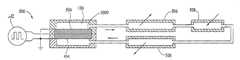
- FIG. 1Ais a front elevation view of a first embodiment of a high flow rate pump in accordance with the present invention
- FIG. 1Bis a top cross-sectional view of the pump of FIG. 1A ;
- FIG. 1Cillustrates enlarged detail view of the pump of FIG. 1A in region 1 C identified in FIG. 1B ;
- FIG. 2is a cross-sectional view of a portion of a second embodiment of an electrokinetic pump in accordance with the invention
- FIG. 3Ais a top cross-sectional view of a stack of three electrokinetic pumps of FIG. 1A ;
- FIG. 3Bis a front elevation view of a simple electrokinetic pump in the stack of FIG. 3A ;
- FIG. 3Cis a front elevation view of the spacer of FIG. 3A ;
- FIG. 3Dis a front elevation view of the cap of FIG. 3A ;
- FIG. 4Ais a current versus voltage plot for a ruthenium oxide pseudocapacitive electrode that can be used in the pump of FIG. 2 ;
- FIG. 4Bis a plot of a calculated current versus voltage for a 5 milli Farad capacitor shown for comparative purposes;
- FIG. 5schematically illustrates a single fluid reciprocating electrokinetic pump driven heat transfer system utilizing an electrokinetic pump according to the present invention
- FIG. 6schematically illustrates a single fluid reciprocating electrokinetic pump driven two phase heat transfer loop using tandem check valves utilizing an electrokinetic pump according to the present invention
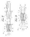
- FIG. 7schematically illustrates a reciprocating electrokinetic pump driven heat transfer system utilizing an electrokinetic pump having two flexible diaphrams according to the present invention
- FIG. 8schematically illustrates an electrokinetic device having a reciprocating electrokinetic pump and four check valves according to the present invention
- FIG. 9schematically illustrates a two-phase heat transfer system that employs a direct electrokinetic pump according to the present invention.
- FIG. 10schematically illustrates a system for contactless dispensing utilizing an electrokinetic pump according to the invention.
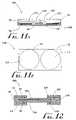
- FIG. 11Ais a side plan view of a glucose monitor that uses an electrokinetic pump in accordance with the present invention.
- FIG. 11Bis a top plan view of the glucose monitor in FIG. 11A ;
- FIG. 12is a cross-sectional view of a dual element electrokinetic pump in accordance with the present invention.
- Double-layer capacitancecapacitance associated with charging of the electrical double layer at an electrode—liquid interface.
- Pseudocapacitancecapacitance associated with an electrochemical oxidation or reduction in which the electrochemical potential depends on the extent of conversion of the electrochemically active species. It is often associated with surface processes. Examples of systems exhibiting pseudocapacitance include hydrous oxides (e.g. ruthenium oxide), intercalation of Li ions into a host material, conducting polymers and hydrogen underpotential deposition on metals.
- hydrous oxidese.g. ruthenium oxide
- Faradaic processoxidation or reduction of a bulk material having an electrochemical potential that is (ideally) constant with extent of conversion.
- Capacitance per areathe capacitance of an electrode material per unit of surface geometric area (i.e. the surface area calculated from the nominal dimensions of the material), having units Farads/cm 2 .
- the geometric areais distinguished from the microscopic surface area. For example, a 1 cm by 1 cm square of aerogel-impregnated carbon paper has a geometric area of 1 cm 2 , but its microscopic area is much higher. For paper 0.25 mm thick the microscopic area is in excess of 1000 cm.
- Capacitive electrodeselectronics made from a material having a double-layer capacitance per area, pseudocapacitance per area, or a combination of the two of at least 10 ⁇ 4 Farads/cm 2 and more preferably, at least 10 ⁇ 2 Farads/cm 2 .
- Pseudocapacitive electrodeselectrodes made from a material having a capacitance of at least 10 ⁇ 4 Farads/cm 2 resulting primarily from pseudocapacitance.
- the present inventionis directed to an electrokinetic device capable of achieving high as well as low flow rates in a closed system without significant evolution of the pump fluid.
- This inventionis directed to electrokinetic pumps having a porous dielectric material between a pair of electrodes that provide for conversion of electronic conduction (external to the pump) to ionic conduction (internal to the pump) at the electrode-fluid interface without significant solvent electrolysis, e.g., hydrolysis in aqueous media, and the resultant generation of gas.
- the electrodesalso work well in non-aqueous systems.
- pumps embodying the inventioncan be used to pump a propylene carbonate solvent with an appropriate electrolyte, such as tetra(alkyl)ammonium tetrafluoroborate.
- a pump 100has a porous dielectric material 102 sandwiched between two capacitive electrodes 104 a and 104 b having a voltage drop therebetween.
- the electrodes 104 a and 104 bpreferably directly contact the porous dielectric material 102 so that the voltage drop across the porous dielectric material preferably is at least 10% of the voltage drop between the electrodes, more preferably at least 50% of the voltage drop between the electrodes, and most preferably at least 85% of the voltage drop between the electrodes.
- This configurationmaximizes the potential across the pump material 102 so that a lower total applied voltage is required for a given flow rate.
- the pump 100It is advantageous for the pump 100 to have a low drive voltage so that it is suitable for integration into compact systems or for close coupling to sensitive electronic devices. Further, sandwich structures with the electrodes 104 a and 104 b in intimate contact with the porous dielectric material 102 prevent the flexure of the porous dielectric material when the pump 100 is configured to pump through the face of the porous dielectric material. Pump flexure reduces the amount of pump fluid pumped in a cycle.
- Electrodes 108are placed in contact with outside surfaces of the electrodes 104 a and 104 b.
- the porous dielectric material 102 , electrodes 104 a and 104 b and the leads 108can be sandwiched between supports 110 , each having a hole 112 so that the pump fluid can flow through the porous dielectric material 102 and the electrodes 104 a and 104 b.
- the supports 110help to maintain the planarity of the pump 100 . Maintaining the planarity of the pump 100 helps to maintain a uniform current flux on the electrodes 104 a and 104 b.
- the pump 100is preferably laminated using a bonding material 116 so that the pump and its lamination forms an integrated assembly that may be in the form of a chip-like assembly as described in U.S. patent application entitled Laminated Flow Device invented by Phillip H. Paul, David W. Neyer, and Jason E. Rehm, filed on Jul. 17, 2002, Ser. No. 10/198,223, and incorporated herein by reference.
- Pump 200 illustrated in FIG. 2is laminated.
- the pump 100can be placed on an etched chip, for example, or incorporated into a flow system by any other means known in the art.
- a spacer 214shown in FIG. 2 , can be used to provide a gap between the electrodes 104 a and 104 b and the porous dielectric material 102 to aid in smoothing the current flux density at the electrodes and to prevent puncture of the porous dielectric material when the electrodes have sharp edges or points.
- Use of the spacer 214is preferable when the electrodes 104 a and 104 b have surface irregularities.
- the electrodes 104 a and 104 b in FIG. 2have lead-out rings 216 , which have flying leads 218 .
- the electrical resistances of the spacers 214are much less than that of the porous dielectric materials 102 .
- supports 110clamp the periphery of the assembled porous dielectric material 102 , electrodes 104 a and 104 b and the leads 108 .
- FIG. 2further support of the assembled porous dielectric material 102 , electrodes 104 a and 104 b, leads 108 , and spacers 214 can be provided by electrode-supports 210 .
- These electrode-supports 210can be, for example, rigid porous frits or sections of honeycomb-like material.
- the flow resistances of the electrode-supports 210 and the electrodes 104 a and 104 bare much less than that of the spacers 214
- the flow resistances of the spacersare much less than that of the porous dielectric material 102 . This can be accomplished by a careful selection of the pore size of each element.
- the electrical resistanceis proportional to the product of formation factor and thickness divided by the area of each element (here ‘thickness’ refers to the dimension of a component along the direction of flow, and ‘area’ refers to the area of the face of an element through which the flow passes).
- the flow resistanceis proportional to the product of formation factor and thickness divided by the product of the area and the square of the pore size for each element.
- the porous dielectric materialto has 0.2 micron pores, a formation factor of 3 and a thickness of 1 mm; the spacers have 3 micron pores, a formation factor of 2 and a thickness of 0.1 mm; the electrodes have 20 micron pores, a formation factor of 3 and a thickness of 2 mm; and the supports have 1 mm pores, a formation factor of 1.2 and a thickness of 3 mm, then the voltage drop across the porous dielectric material is then 88% of the total applied voltage and the flow conductances (i.e. the inverse of the flow resistance) of the porous dielectric, the spacer, the electrode and the support are then about 0.02, 63, 94 and 3900 ml per minute per psi per square cm, respectively.
- the diameter of the faces of the pumps 100 and 200 , which pump fluid can flow through,are each larger than the thicknesses of the respective pumps so that both pumps resemble a coin, with the flow through the face, as opposed to most low-flow-rate and/or high-pressure designs that are more rod-like with the flow along a longitudinal axis.
- Pumps embodying the inventiondo not have to have cylindrical symmetry, but can have any shape.
- the area of the pumps 100 and 200 through which fluid can flowis selected to meet flow rate requirements.
- a pump running at about 3Vcan achieve an open-load flowrate of about 1.2 mL/min per cm 2 thus an open-load flowrate of 10 mL/min can be achieved with a pump having an area of about 8.8 cm 2 .
- the same flow ratecan be achieved by running in parallel multiple pumps having smaller areas.
- FIG. 3AA compact parallel multiple element pump 300 is shown in FIG. 3A .
- This multiple element pump 300comprises a stack of pumps 100 and spacers 214 finished with caps 302 .
- the direction of each pump 100 elementi.e. polarity of the driving voltage, preferably is reversed relative to the adjacent pump so that no voltage drop is applied across the openings created by the spacers 214 .
- Any number of pumpscan be combined to form a parallel pump and any size stack can be made out of just three types of elements, caps 302 shown in FIG. 3D , spacers 214 shown in FIG. 3C and pumps 100 shown in FIGS. 3 B and 1 A- 1 C.
- the flow rate of the parallel pump 300is the sum of the flow rates of each of the pumps 100 .
- the pumps 100may also be configured in series as described by Rakestraw et al. in U.S. patent application Ser. No. 10/066,528, filed Jan. 31, 2002 and entitled Variable Potential Electrokinetic Devices and incorporated herein by reference and act as a pressure amplifier for higher-pressure operation.
- the supports 110can be formed of any material known in the art that provides sufficient mechanical strength and dielectric strength, such as: polyetherimide (PEI, known by the brand name Ultem), polyethersulfone (PES, known by the brand name Victrex), polyethylene terephthalate (PET, known by the brand name Dacron).
- PEIpolyetherimide
- PESpolyethersulfone
- PETpolyethylene terephthalate
- the electrode-supports 210can be a 3-mm thick honeycomb having 1 mm cells, 50-micron cell wall thickness, and a 92% open area, i.e., 92% of the total area of the electrode-support is open, for example.
- the type, cell size, and thickness of the electrode-supports 210are preferably selected to provide the mechanical strength to maintain the necessary degree of planarity of the pump. It is preferable that any flow-induced flexure of the electrodes (and similar flexure of the pump medium sandwiched between the electrodes) be limited to some small fraction (preferably less than ten percent) of the displacement of the liquid per one-half cycle. For example: a pump running at 15 mL/min, with an oscillatory cycle time of 8 seconds and an area of about 12 cm 2 , gives a liquid displacement of about 0.8 mm per one-half cycle. In this example, it is preferable that the electrodes be supported in a fashion to limit any electrode flexure to less than 0.08 mm.
- the electrical contacts to the electrodesare formed from a metal, preferably platinum, that is electrochemically stable (i.e. not subject to redox reactions) under the electrochemical conditions encountered within the pump liquid environment.
- the electrical contactsmay be in the form of a wire lead that may also serve as a flying lead, or a foil or as a thin layer deposited on an insulating support. Flying leads that are connected to the electrode contacting leads and do not contact the liquid may be of any type common in electrical components and wiring.
- the spacer 214can be formed of any large pore dielectric material, such as acrylic copolymer foam membrane or polypropylene.
- the thickness of the spacer 214is as small as possible but greater than one half of the scale of any irregularities in the electrodes 104 a and 104 b, e.g. slightly thicker than one half of the wire diameter for a wire mesh electrode.
- the spacercan have 5-10 micron pores, a formation factor of 1.7 and a 50 micron thickness.
- the electrodes 104 a and 104 bare open and the electrodes have a flow through design that covers an entire face of the porous dielectric material 102 and a geometric structure that provides good fluid exchange at all the current carrying surfaces to facilitate the replenishment of the ions at the electrodes.
- the electrode geometric areapreferably matches the geometric area of the pump medium. For example, in a case where the pump medium has a disc of diameter 13 mm, electrodes with 11 mm diameters have been used.
- the electrodes 104 a and 104 bare preferably free of sharp edges and points so as to support without puncturing the porous dielectric material 102 and to provide a uniform current flux.
- the electrodescan be in the form of carbon paper, carbon foam, perforated plates, porous frits, porous membranes, or wire mesh, for example.
- the electrodes 104 a and 104 bpreferably are made from a material having a double-layer capacitance of at least 10 ⁇ 4 Farads/cm 2 , more preferably, at least 10 ⁇ 2 Farads/cm 2 , as these electrodes can function with a wide range of pump fluids, i.e., any fluid having a pH value and an ionic content compatible with the porous dielectric material 104 , whereas pseudocapacitive electrodes can function with a limited range of pump fluids as they need to be supplied reactants in order to avoid electrolysis of the pump fluid.
- Carbon paper impregnated with carbon aerogelis the most preferable electrode material as it has a substantial double-layer capacitance and is free of sharp edges and points.
- the high capacitance of this materialarises from its large microscopic surface area for a given geometric surface area.
- the double layer capacitanceis about 10 mF/cm 2 and at low currents, (e.g. 1 microamp per square cm) the double-layer capacitance is about 1 F/cm 2 .
- Capacitive electrodescan be formed of materials other than carbon, even though carbon is preferred as it is an inert element and therefore reactions are slow when the voltage applied to the electrodes accidentally exceeds the electrolysis threshold. Capacitive electrodes can be formed of any conductor having a high microscopic surface area, such as sintered metal.
- the electrode chemistryis arranged to minimize any irreversible electro-chemical reactions that might alter the pump fluid and provide for conversion from electronic conduction to ionic conduction at the electrode-fluid interface, so that gaseous products are not produced and irreversible alteration of the pump fluid or electrode materials are not involved. This is accomplished by limiting the rate of unwanted chemical reactions at the electrodes 104 a and 104 b by careful optimization of the combination of: the pump fluid, electrode material, the porous dielectric material 102 , physical geometry of the pump, the applied potential, and the current flux density at the electrodes 104 a and 104 b.
- Examples of possible pseudocapacitive electrode-fluid combinationsinclude:
- Thiscan be iridium-, vanadium-, or ruthenium-oxides. These oxides are relatively insoluble in water and many other solvents. Advantage is taken of the multiple oxidation states of the metals but the redox reaction takes place in the solid phase and the charge can be carried as OH ⁇ or H + ions in the fluid.
- Li + ionsmay be inserted into solids like titanium, molybdenum di-sulfides, certain polymers or carbon. Redox reactions in the solid results in dispensing or uptake of the Li + ions to or from the fluid. These ions are stable when stored in the solid and solids with intercalated ions are stable when exposed to the transport fluid, although some are reactive with H 2 O.
- inorganic porous dielectric materialsare used and more preferably, Anopore® membranes, are employed as the porous dielectric pump material 102 in order to provide both a thin pump (e.g. 60 to 2000 microns), and therefore low drive voltage, and narrow pore size distribution, as well as the capability to have both positive and negative zeta potentials.
- a narrow pore size distributionis desirable as it makes the pump 100 more efficient. Large pores cause the pump 100 to have reduced pressure performance and pores that are too narrow cause increased charge layer overlap, which decreases the flow rate.
- Anapore® membranesare composed of a high purity alumina that is highly porous, where the pores are in the form of a substantially close-packed hexagonal array with a pore diameter of approximately 200 nm.
- the porespreferably have a diameter in the range of 50-500 nm because it is desirable that the pores be as small as possible to achieve high pump stall pressure but still be large enough to avoid substantial double-layer overlap.
- Additives to the fluid that provide polyvalent ions having a charge sign opposite to that of the zeta potential of the porous dielectric materialare preferably avoided.
- the porous dielectric material 102is comprised of a positive zeta potential material
- phosphates, borates and citratespreferably are avoided.
- a negative zeta potential materialbarium and calcium preferably are avoided.
- the desired strategyis to apply a current to the electrodes 104 a and 104 b to produce a desired flow rate while charging the double-layer capacitance of the electrodes during the first half of the pump cycle.
- the polarity of the applied fieldis then changed before Faradaic processes begin, thereby discharging the double-layer capacitance of the electrodes 104 a and 104 b and then recharging the electrodes with the opposite polarity causing the pump fluid to flow in the opposite direction during the second half of the pump cycle.
- This alternation of polarityis referred to here as “AC” operation.
- an applied current (I) of 1 mA and a capacitance (C) of 0.3 Fresults in a voltage rise (dV/dt) of 3.3 mV/sec. At this rate it takes about 5 minutes to increase 1 V. At low enough currents, the time between required polarity changes may be very long and the pump 100 can effectively operate in “DC” mode for some operations.
- the electrodes 104 a and 104 bsupply the current required, even for high flow rates, e.g., greater than 1 mL/min, without significant electrolysis of the pump fluid or significant evolution of the pH of the pump fluid. Avoidance of significant pH evolution of the pump fluid can be accomplished by not allowing the voltage drop between the electrodes 104 a and 104 b and the liquid to exceed the threshold for Faradaic electrochemical reactions, which start at approximately 1.2V for water.
- the double-layer capacitance or the pseudocapacitance of the electrodes 104 a and 104 bpreferably is charged prior to the beginning of bulk Faradaic processes.
- Typical values of double layer capacitance of a plane metal surfaceare 20 to 30 micro Farads/cm 2 . This value can be substantially increased using methods well-known in the electrochemical arts (e.g. surface roughening, surface etching, platinization of platinum).
- the double-layer capacitance of the electrodes 104 a and 104 bis preferably at least 10 ⁇ 4 Farads/cm 2 and more preferably at least 10 ⁇ 2 Farads/cm 2 .
- reactantsare consumed at the electrodes. When all of the reactants are consumed, gas is produced and the pump fluid may be irreversibly altered. Therefore, preferably the reactants are replenished or current stops flowing through the electrodes before all of the reactants are consumed.
- the rate that the reactants are supplied to the electrodes 104 a and 104 bpreferably is high enough to provide for the charge transfer rate required by the applied current. Otherwise, the potential at the electrodes 104 a and 104 b will increase until some other electrode reaction occurs that provides for the charge transfer rate required by the current. This reaction may not be reversible.
- the current that can be drawnhence the electrokinetic flow rate is limited by the transport rate of limiting ionic reactants to or from the electrodes 104 a and 104 b.
- the design of the pump 100 when pseudocapacitive electrodes are usedis thus a careful balance between: increasing ionic concentration to support reversible electrode reactions and decreasing ionic concentration to draw less current to prevent irreversible evolution of the pump fluid.
- FIG. 4AAn example of the current versus voltage behavior (a cyclic voltammogram) of a ruthenium oxide (RuO 2 ) pseudocapacitive electrode is given in FIG. 4A .
- the calculated cyclic voltammogram for a 5 mF capacitoris shown for comparison in FIG. 4B .
- the surface area of the pseudocapacitive electrodewas about 0.1 cm 2 .
- the cyclic voltammogram for an electrode based on bulk Faradaic processeswould appear as a nearly vertical line in these plots.
- the current versus voltage behavior that arises from intercalation of an ion, e.g. Li + , into a host matrix or a conducting polymer electrodeis similar to that of a ruthenium oxide electrode.
- Pseudocapacitive electrodeswhich operate using a surface Faradaic electrochemical process, sacrifice some of the chemical universality of capacitive electrodes, which can be charged by almost any ion.
- Pseudocapacitanceis usually centered on the uptake and release of a specific ion, H + for RuO 2 and Li + for intercalation, for example. Therefore, pseudocapacitive electrodes are compatible with a smaller number of liquids as RuO 2 systems are usually run under acidic conditions and many Li + intercalation compounds are unstable in water.
- electrokinetic pumps embodying the inventioncan be controlled with either voltage or current programming.
- the simplest schemeis constant current operation. Under these conditions the electrode-liquid potential ramps linearly in time.
- the charge transferred on each half of the cycleis preferably balanced. This is to avoid the net charging of the electrodes 104 a and 104 b.
- Equal transfer of charge on each half of the cyclecan be accomplished by driving the pump 100 with a symmetric constant-current square wave.
- the time of each half of the cyclepreferably is adjusted so that the current-time product is equal on both halves of the cycle.
- the pump 100can be driven with a constant voltage for a fixed time period on the first half of the cycle.
- the currentis integrated to measure the total charge transferred.
- the reverse currentis integrated.
- the second half of the cyclepreferably continues until the integrated current of the second half equals that of the first half of the cycle.
- This mode of operationmay give more precise delivery of the pump fluid.
- Even more complex tailored waveforms, controlled current or controlled voltage,are possible.
- an appropriate voltage waveformcan be applied, a voltage step followed by a voltage ramp, for example.
- a number of other voltage- or current-programmed control strategiesare possible.
- a constant current power supplycan be used to provide power to the electrodes.
- Methods of providing a constant currentare well-known in the electrical arts and include, for example, an operational amplifier current regulator or a JFET current limiter.
- the power supplycan be connected to the flying leads 218 via a timed double-pole/double-throw switch that reverses the potential at fixed intervals.
- Using a more sophisticated circuit, which adds the ability to vary the regulated current,will provide the capacity to vary the flow rate in response to a control signal.
- the potentialis reversed when the total charge reaches a fixed limit.
- a time-integrated signal from a current shunt or a signal from a charge integratorpreferably is employed to monitor the charge supplied to the pump 100 . Once the charge reaches a preset level, the polarity is reversed and integrated signal from the current shunt or charge integrator is reset. Then the process is repeated.
- the pump flow rate and pressurecan be modulated by varying the electrical input.
- the electrical inputcan be varied manually or by a feedback loop. It may be desirable to vary the flow rate and/or the pressure, for example: to vary a heat transfer rate or stabilize a temperature in response to a measured temperature or heat flux; to provide a given flow rate or stabilize a flow rate in response to the signal from a flowmeter; to provide a given pressure or stabilize a pressure in response to a signal from a pressure gauge; to provide a given actuator displacement or stabilize an actuator in response to a signal from displacement transducer, velocity meter, or accelerometer.
- any of the embodiments of the high flow rate electrokinetic pumpcan be stacked, arranged in several different configurations and used in conjunction with one or more check valves to fit a specific application.
- the examples given herelist some of the different types of pumps, pump configurations, check valve configurations and types of heat transfer cycles.
- FIGS. 1A-1C and 2Single element pumps are illustrated in FIGS. 1A-1C and 2 .
- Single element pumpshave a single porous dielectric material 102 .
- FIG. 3illustrates a set of single element pumps arranged in a parallel array.
- Dual element pumps 1000illustrated in FIGS. 5 and 6 and shown in detail in FIG. 12 , contain a porous dielectric material 504 having a positive zeta potential and a porous dielectric material 505 having a negative zeta potential.
- Three electrodesare used in the dual element pumps.
- Electrode 104 bis located between the two porous dielectric materials 504 and 505 adjacent to the inside face of each porous dielectric material and electrodes 104 a and 104 c are located on or adjacent to the outside face of each of the porous dielectric materials.
- Electrodes 104 a, 104 b and 104 care connected to an external power supply (not shown) via leads 1010 , 1020 and 1030 , respectively.
- the electrodes 104 a and 104 cpreferably are held at ground and the driving voltage from power supply 502 is applied to the center electrode 104 b.
- multi-element pumpshaving a plurality of sheets of porous dielectric materials and a plurality of electrodes, one electrode being located between every two adjacent sheets.
- the value of the zeta potential of each sheet of porous dielectric materialhas a sign opposite to that of any adjacent sheet of porous dielectric material.
- the porous dielectric material in a direct pumppumps the fluid in the flow path directly. For example, see FIGS. 5 and 6 .
- Indirect pumpssuch as those illustrated in FIGS. 7 and 8 , have a flexible impermeable barrier 702 , such as a membrane or bellows, physically separating the fluid 106 in the pump 100 and a first flow path 716 from a fluid 712 in a second, external fluid path 714 .
- a flexible impermeable barrier 702such as a membrane or bellows
- Configurations with two check valvesgive unidirectional flow, but only pump fluid on one half of the pump cycle, there is no flow on the other half, see for example, FIG. 6 .
- Configurations with four check valvesgive unidirectional flow and utilize the pump on both halves of the pump cycle, see, for example, FIG. 8 .
- FIG. 8there are two separate flow paths 714 and 814 external to the pump 100 .
- the first external fluid 712is pumped through fluid inlet 816 and the check valve 610 a of the first external flow path 714
- the second external fluid 812is pumped through check valve 610 d and out of fluid outlet 818 of the second external flow path 814 .
- the second external fluid 812is pumped through fluid inlet 820 and check valve 610 c of the second external flow path 814 , while the first external fluid is pumped though the check valve 610 b and out of fluid outlet 822 of the first external flow path 714 .
- the external fluids 712 and 714may be the same or different fluids.
- the external flow paths 714 and 814can be combined before the check valves 610 a and 610 c or after the check valves 610 b and 610 d or both.
- FIG. 5illustrates a single fluid reciprocating electrokinetic pump driven heat transfer system 500 .
- the pump 1000pumps fluid counterclockwise through the system 500 and when a negative voltage is applied to the center electrode, fluid flows clockwise through the system.
- Fluidabsorbs heat in the primary heat exchanger 508 and radiates heat in the secondary heat exchangers 506 .
- Two-phase heat exchangersrely on a phase change such as evaporation to remove heat.
- a direct pumpis used in a two-phase heat exchange system
- the entire systemis preferably configured to recycle the concentrated electrolyte deposited during the evaporation process. This can be done, for example, by using a volatile ionic species, e.g. acetic acid in water.
- Use of an indirect pumpseparates the pump liquid, which generally contains added ions, from the heat-transfer liquid.
- FIG. 6illustrates an electrokinetic pump driven two-phase heat transfer loop 600 using a direct pump and tandem check valves 610 and 611 .
- a negative voltageis applied to the second electrode 104 b of the pump 1000 the junction of the two check valves is pressurized, the first check valve 610 is closed and the second check valve is opened, and liquid flows towards the evaporator 608 .
- the evaporator 608absorbs heat and changes the liquid 106 into vapor 614 .
- the vapor 614travels to the condenser 606 where heat is removed and vapor 614 is transformed back to liquid 106 .
- check valve 611When a positive voltage is applied to the middle electrode 104 b, check valve 611 is closed preventing liquid flow in the evaporator/condenser loop and check valve 610 is opened allowing flow around the pump 1000 .
- the second half of the pump cyclewhen a positive voltage is applied to the second electrode 104 b, can be used for electrode regeneration if the charge per half-cycle is balanced.
- FIG. 9shows a two-phase heat transfer system that employs direct pumping. Heat is transferred to liquid 1220 in the evaporator 1270 . The addition of heat converts some portion of the liquid 1220 into a vapor 1230 that convects through vapor transfer lines 1280 to condensers 1240 and 1250 . Heat is removed from condensers 1250 and 1240 and the resulting drop in temperature results in condensation of vapor 1230 . This condensate returns by capillary action through wicks 1260 to the liquid 1220 in the condensers.
- Pump 100operates in an AC mode. During the first half-cycle the pump 100 pushes liquid 1220 from liquid transfer line 1210 to the condenser 1240 and through the liquid transfer line 1310 to evaporator 1270 and also draws liquid (and possibly some vapor) from evaporator 1270 through transfer line 1320 to condenser 1250 . On the second half cycle this process is reversed.
- the condenser wicks 1260are made of a porous material that is selected to provide a substantially high resistance to pressure driven liquid flow relative to that of liquid transfer lines 1320 and 1310 .
- the primary result of operation of the pumpis displacement of liquid through the transfer lines 1310 and 1320 .
- the amount of liquid displaced by the pump per half-cyclepreferably is greater than the amount of evaporator liquid 1220 vaporized per pump half-cycle. In this manner some liquid is continuously present in the evaporator. Further, the amount of liquid displaced by the pump per half-cycle preferably is sufficient so that fresh liquid from a condenser fully refills the evaporator and so that remaining liquid in the evaporator is fully discharged into a condenser. That is the amount of liquid dispensed per pump half-cycle should exceed the volume of liquid within transfer lines 1310 and 1320 plus the volume of liquid evaporated per half-cycle plus the amount of liquid remaining in the evaporator per half-cycle. In this manner any concentrate, which can result from concentration of any electrolyte as a consequence of distillation of liquid in the evaporator, will be transported by liquid convection and re-diluted in the condensers.
- this systemIt is preferable to operate this system of evaporator and condensers at the vapor pressure of the operating liquid.
- the entire systemis preferably vacuum leak tight. Prior to operation, the system pressure is reduced to the vapor pressure of the liquid by a vacuum pump or other means known in the arts and then sealed using a seal-off valve or other means known in the arts.
- the source of heat input to any of the heat transfer systems disclosedcould be, for example, an electronic circuit, such as a computer CPU or a microwave amplifier, that can be directly mounted on or integrated to the evaporators or primary heat exchangers.
- the removal of heat from the condensers or secondary heat exchangerscan be via a passively or actively cooled fin or by any other means known in the arts of heat transfer.
- Any combination of pump type, pump configuration, check valve configuration and type of heat transfer cyclecan be used with a pump utilizing capacitive, Faradaic or pseudocapacitive electrodes.
- Other specific applications of electrokinetic pumps embodying the invention aside from heat transferinclude, but are not limited to, drug delivery, glucose monitors, fuel cells, actuators, and liquid dispensers.
- a high flow rate electrokinetic pump having features of the present inventioncan be used in liquid dispensing applications that require precise delivery of a given volume of fluid.
- the applicationrequires contactless dispensing. That is, the volume of fluid is ejected from a dispenser into a receptacle without the nozzle of the dispenser touching fluid in the receptacle vessel.
- the configuration of an electrokinetic pump having two check valves, shown in FIG. 10may be used.
- the pump 100Upon charging the electrodes, the pump 100 withdraws fluid 1006 from a reservoir 1008 . The fluid 1006 then passes through a first check valve 610 . Upon discharging and recharging the electrodes with the opposite charge, the pump 100 then reverses direction and pushes fluid through the second check valve 611 and out of the nozzle 1010 into a receiving vessel 1012 . Precise programmable contactless fluid dispensing across the 10-80 ⁇ L range using 0.5 to 2 sec dispense times has been demonstrated.
- This embodimentcan be a stand-alone component of a dispensing system or can be configured to fit in the bottom of a chemical reagent container.
- the conduits of the electrokinetic pumpcan be comprised of channels in a plastic plate.
- the nozzle 1010can be directly mounted on the plate, and low-profile (e.g. “umbrella” type) check valves can be utilized.
- Electrokinetic pumps embodying the present inventioncan be used in these applications as well.
- Low-flow-rate pumps in accordance with the present inventioncan be used in a glucose monitor that delivers 100 nL/min. At this flow rate, electrodes having an area of approximately 1.4 cm 2 can run for approximately 7 days before the direction of the current must be changed.
- FIGS. 11A and 11BA design for a low-flow-rate pump that could be used as a glucose monitor pump 1100 is shown in FIGS. 11A and 11B .
- the pump systempumps fluid indirectly.
- the pump systemhas a first reservoir 1102 above a flexible barrier 702 .
- the first reservoiris external to the pump and is filled with the liquid to be delivered (Ringer's solution, for example) 1112 .
- All of the pump fluid 106remains below the flexible barriers 702 .
- the pump fluid 106is pushed through the pump, which extends the flexible barrier 702 and dispenses the liquid 1112 .
- the liquid 1112circulates through an external loop (not shown), which may contain, for example, a subcutaneous sampling membrane and a glucose sensor, then flows to a second reservoir 1103 external to the pump.
- This “push-pull” operation of the pumpis useful for the glucose sensor (not shown), since it is preferable to keep the sensor at ambient pressure.
- the design in FIG. 11may be “folded” such that the reservoirs 1102 and 1103 are stacked to change the footprint of the pump system 1100 .
- the fact that the electrodes 102 do not generate gas and do not alter the pHsimplifies the design considerably. It eliminates the need to vent-to-ambient gases produced by electrolysis and eliminates the need to provide a means of controlling the pH of the fluid reservoir (e.g. ion exchange resin in the pump liquid reservoirs).
- Electrokinetic pumps embodying the inventioninclude: gas-free operation, the ability to draw very high current densities (in excess of 20 mA/cm 2 )and the ability to cycle many times (in excess of 10 million cycles with no apparent change in operating characteristics). Electrokinetic pumps embodying the invention and using capacitive electrodes have the additional advantage of compatibility with a nearly unlimited number of chemical systems.
- the pump 100 illustrated in FIGS. 1A-1Chaving a porous dielectric material of a 25-mm diameter Anopore® membrane and 19-mm diameter electrodes in the form of carbon paper impregnated with carbon aerogel, has been used to pump a 1 millimolar sodium acetate buffer having a pH of about 5 at flow rates up to 10 mL/min, about 170 microliters/second, at a driving current of 40 mA.
- the pump illustrated in FIGS. 1A-1Chaving a porous dielectric material of a 13-mm diameter Durapore-Z® membrane, and 11 mm diameter electrodes in the form of carbon paper impregnated with carbon aerogel, and an 8-mm aperture in the PEI, was driven with a +/ ⁇ 0.5 mA square wave with a 10 second period.
- the pumpdelivered 0.5 mM lithium chloride at 0.8 microliters/second. It was operated for a total of 35 hours without degradation.
- the carbon aerogel/Durapore® membrane sandwiched pumpwas operated in two additional manners.
- an asymmetric driving currentwas used to achieve pulsed operation.
- 0.2 mAwas applied for 9.5 seconds and then ⁇ 3.8 mA was applied for 0.5 seconds.
- fluidwas drawn slowly backward through the pump.
- fluidwas pushed forward, delivering 3 microliters. This is the type of action that can be used for dispensing a liquid.
- the pump illustrated in FIGS. 1A-1Cseparately pumped 0.5 mM of lithium chloride, 34 mM acetic acid, and about 34 mM carbonic acid.
- the pumphad carbon mesh electrodes and an organic amine-derivatized membrane as the porous dielectric material.
- an electrokinetic pump having features of the present inventioncan include three or more porous dielectric pump elements. Therefore, the spirit and scope of the appended claims should not be limited to the description of the preferred versions contained herein.
Landscapes
- Engineering & Computer Science (AREA)
- Mechanical Engineering (AREA)
- General Engineering & Computer Science (AREA)
- Physical Or Chemical Processes And Apparatus (AREA)
- Structures Of Non-Positive Displacement Pumps (AREA)
- Reciprocating Pumps (AREA)
Abstract
Description
Claims (24)
Priority Applications (15)
| Application Number | Priority Date | Filing Date | Title |
|---|---|---|---|
| US10/273,723US7235164B2 (en) | 2002-10-18 | 2002-10-18 | Electrokinetic pump having capacitive electrodes |
| US10/322,083US7267753B2 (en) | 2002-10-18 | 2002-12-17 | Electrokinetic device having capacitive electrodes |
| JP2004545416AJP4684653B2 (en) | 2002-10-18 | 2003-10-17 | Electrokinetic device |
| EP03809093AEP1556612B1 (en) | 2002-10-18 | 2003-10-17 | Electrokinetic devices |
| CA2502671ACA2502671C (en) | 2002-10-18 | 2003-10-17 | Electrokinetic devices |
| AT03809093TATE416310T1 (en) | 2002-10-18 | 2003-10-17 | ELECTROKINETIC DEVICES |
| AU2003277420AAU2003277420C1 (en) | 2002-10-18 | 2003-10-17 | Electrokinetic devices |
| PCT/US2003/032895WO2004036041A2 (en) | 2002-10-18 | 2003-10-17 | Electrokinetic devices |
| DE60325082TDE60325082D1 (en) | 2002-10-18 | 2003-10-17 | ELECTROKINETIC DEVICES |
| US11/112,867US7517440B2 (en) | 2002-07-17 | 2005-04-21 | Electrokinetic delivery systems, devices and methods |
| US11/684,500US7875159B2 (en) | 2002-10-18 | 2007-03-09 | Electrokinetic pump having capacitive electrodes |
| US11/766,678US20080173545A1 (en) | 2002-10-18 | 2007-06-21 | Electrokinetic Pump Having Capacitive Electrodes |
| US13/013,484US8192604B2 (en) | 2002-10-18 | 2011-01-25 | Electrokinetic pump having capacitive electrodes |
| US13/462,634US8715480B2 (en) | 2002-10-18 | 2012-05-02 | Electrokinetic pump having capacitive electrodes |
| US14/265,069US20140231258A1 (en) | 2002-10-18 | 2014-04-29 | Electrokinetic pump having capacitive electrodes |
Applications Claiming Priority (1)
| Application Number | Priority Date | Filing Date | Title |
|---|---|---|---|
| US10/273,723US7235164B2 (en) | 2002-10-18 | 2002-10-18 | Electrokinetic pump having capacitive electrodes |
Related Parent Applications (1)
| Application Number | Title | Priority Date | Filing Date |
|---|---|---|---|
| US10/198,223Continuation-In-PartUS7364647B2 (en) | 2002-07-17 | 2002-07-17 | Laminated flow device |
Related Child Applications (4)
| Application Number | Title | Priority Date | Filing Date |
|---|---|---|---|
| US10/322,083Continuation-In-PartUS7267753B2 (en) | 2002-07-17 | 2002-12-17 | Electrokinetic device having capacitive electrodes |
| US11/112,867Continuation-In-PartUS7517440B2 (en) | 2002-07-17 | 2005-04-21 | Electrokinetic delivery systems, devices and methods |
| US11/684,500DivisionUS7875159B2 (en) | 2002-10-18 | 2007-03-09 | Electrokinetic pump having capacitive electrodes |
| US11/766,678ContinuationUS20080173545A1 (en) | 2002-10-18 | 2007-06-21 | Electrokinetic Pump Having Capacitive Electrodes |
Publications (2)
| Publication Number | Publication Date |
|---|---|
| US20040074768A1 US20040074768A1 (en) | 2004-04-22 |
| US7235164B2true US7235164B2 (en) | 2007-06-26 |
Family
ID=32092877
Family Applications (7)
| Application Number | Title | Priority Date | Filing Date |
|---|---|---|---|
| US10/273,723Expired - LifetimeUS7235164B2 (en) | 2002-07-17 | 2002-10-18 | Electrokinetic pump having capacitive electrodes |
| US10/322,083Expired - Fee RelatedUS7267753B2 (en) | 2002-07-17 | 2002-12-17 | Electrokinetic device having capacitive electrodes |
| US11/684,500Expired - Fee RelatedUS7875159B2 (en) | 2002-10-18 | 2007-03-09 | Electrokinetic pump having capacitive electrodes |
| US11/766,678AbandonedUS20080173545A1 (en) | 2002-10-18 | 2007-06-21 | Electrokinetic Pump Having Capacitive Electrodes |
| US13/013,484Expired - Fee RelatedUS8192604B2 (en) | 2002-10-18 | 2011-01-25 | Electrokinetic pump having capacitive electrodes |
| US13/462,634Expired - Fee RelatedUS8715480B2 (en) | 2002-10-18 | 2012-05-02 | Electrokinetic pump having capacitive electrodes |
| US14/265,069AbandonedUS20140231258A1 (en) | 2002-10-18 | 2014-04-29 | Electrokinetic pump having capacitive electrodes |
Family Applications After (6)
| Application Number | Title | Priority Date | Filing Date |
|---|---|---|---|
| US10/322,083Expired - Fee RelatedUS7267753B2 (en) | 2002-07-17 | 2002-12-17 | Electrokinetic device having capacitive electrodes |
| US11/684,500Expired - Fee RelatedUS7875159B2 (en) | 2002-10-18 | 2007-03-09 | Electrokinetic pump having capacitive electrodes |
| US11/766,678AbandonedUS20080173545A1 (en) | 2002-10-18 | 2007-06-21 | Electrokinetic Pump Having Capacitive Electrodes |
| US13/013,484Expired - Fee RelatedUS8192604B2 (en) | 2002-10-18 | 2011-01-25 | Electrokinetic pump having capacitive electrodes |
| US13/462,634Expired - Fee RelatedUS8715480B2 (en) | 2002-10-18 | 2012-05-02 | Electrokinetic pump having capacitive electrodes |
| US14/265,069AbandonedUS20140231258A1 (en) | 2002-10-18 | 2014-04-29 | Electrokinetic pump having capacitive electrodes |
Country Status (4)
| Country | Link |
|---|---|
| US (7) | US7235164B2 (en) |
| JP (1) | JP4684653B2 (en) |
| AT (1) | ATE416310T1 (en) |
| DE (1) | DE60325082D1 (en) |
Cited By (30)
| Publication number | Priority date | Publication date | Assignee | Title |
|---|---|---|---|---|
| US20050230080A1 (en)* | 2004-04-19 | 2005-10-20 | Paul Phillip H | Electrokinetic pump driven heat transfer system |
| US20050247558A1 (en)* | 2002-07-17 | 2005-11-10 | Anex Deon S | Electrokinetic delivery systems, devices and methods |
| US20050274200A1 (en)* | 2004-05-25 | 2005-12-15 | Henry Manus P | Flowmeter batching techniques |
| US20060207883A1 (en)* | 2004-10-19 | 2006-09-21 | Koval Carl A | Electrochemical high pressure pump |
| US20070068815A1 (en)* | 2005-09-26 | 2007-03-29 | Industrial Technology Research Institute | Micro electro-kinetic pump having a nano porous membrane |
| US20080173545A1 (en)* | 2002-10-18 | 2008-07-24 | Eksigent Technologies, Llc | Electrokinetic Pump Having Capacitive Electrodes |
| US20090148308A1 (en)* | 2007-12-11 | 2009-06-11 | Saleki Mansour A | Electrokinetic Pump with Fixed Stroke Volume |
| US20090209911A1 (en)* | 2008-02-14 | 2009-08-20 | Honeywell International Inc. | Apparatus and method for portable liquid drug delivery |
| US7744738B1 (en)* | 2003-10-16 | 2010-06-29 | The University Of Notre Dame | Method and apparatus for rapid particle manipulation and characterization |
| US20100313683A1 (en)* | 2009-06-12 | 2010-12-16 | Nickel Troy D | Multiple-Specimen Device Testing with Particle Measurement |
| US7867592B2 (en) | 2007-01-30 | 2011-01-11 | Eksigent Technologies, Inc. | Methods, compositions and devices, including electroosmotic pumps, comprising coated porous surfaces |
| US8152477B2 (en) | 2005-11-23 | 2012-04-10 | Eksigent Technologies, Llc | Electrokinetic pump designs and drug delivery systems |
| US8287495B2 (en) | 2009-07-30 | 2012-10-16 | Tandem Diabetes Care, Inc. | Infusion pump system with disposable cartridge having pressure venting and pressure feedback |
| US8408421B2 (en) | 2008-09-16 | 2013-04-02 | Tandem Diabetes Care, Inc. | Flow regulating stopcocks and related methods |
| US20130156615A1 (en)* | 2011-12-15 | 2013-06-20 | General Electric Company | Self contained electroosmotic pump and method of making thereof |
| US20130153425A1 (en)* | 2011-12-15 | 2013-06-20 | General Electric Company | Electroosmotic pump and method of use thereof |
| US8650937B2 (en) | 2008-09-19 | 2014-02-18 | Tandem Diabetes Care, Inc. | Solute concentration measurement device and related methods |
| WO2014193979A1 (en)* | 2013-05-28 | 2014-12-04 | Eksigent Technologies Llc | Electrokinetic pumps |
| US8945094B2 (en) | 2010-09-08 | 2015-02-03 | Honeywell International Inc. | Apparatus and method for medication delivery using single input-single output (SISO) model predictive control |
| US8979511B2 (en) | 2011-05-05 | 2015-03-17 | Eksigent Technologies, Llc | Gel coupling diaphragm for electrokinetic delivery systems |
| US8986253B2 (en) | 2008-01-25 | 2015-03-24 | Tandem Diabetes Care, Inc. | Two chamber pumps and related methods |
| US9314567B2 (en) | 2010-03-09 | 2016-04-19 | Board Of Regents Of The University Of Texas System | Electro-osmotic pumps, systems, methods, and compositions |
| US9416777B2 (en) | 2014-09-26 | 2016-08-16 | Becton, Dickinson And Company | Control circuits for electrochemical pump with E-valves |
| US9555186B2 (en) | 2012-06-05 | 2017-01-31 | Tandem Diabetes Care, Inc. | Infusion pump system with disposable cartridge having pressure venting and pressure feedback |
| US9931462B2 (en) | 2012-09-21 | 2018-04-03 | Board Of Regents Of The University Of Texas System | Electro-osmotic pumps with electrodes comprising a lanthanide oxide or an actinide oxide |
| US9962486B2 (en) | 2013-03-14 | 2018-05-08 | Tandem Diabetes Care, Inc. | System and method for detecting occlusions in an infusion pump |
| US10258736B2 (en) | 2012-05-17 | 2019-04-16 | Tandem Diabetes Care, Inc. | Systems including vial adapter for fluid transfer |
| US20220095484A1 (en)* | 2021-12-03 | 2022-03-24 | Intel Corporation | Vapor chamber with ionized fluid |
| US20230417227A1 (en)* | 2022-06-25 | 2023-12-28 | EvansWerks, Inc. | Pumping systems and methods |
| US12363864B2 (en) | 2022-06-25 | 2025-07-15 | EvansWerks, Inc. | Cooling system and methods |
Families Citing this family (65)
| Publication number | Priority date | Publication date | Assignee | Title |
|---|---|---|---|---|
| US20030098661A1 (en)* | 2001-11-29 | 2003-05-29 | Ken Stewart-Smith | Control system for vehicle seats |
| WO2004015378A1 (en)* | 2002-07-05 | 2004-02-19 | Gaspardo Seminatrici S.P.A. | A volumetric metering device for the metered delivery of granular and powdery materials, particularly for machines for distributing the said materials |
| US7364647B2 (en)* | 2002-07-17 | 2008-04-29 | Eksigent Technologies Llc | Laminated flow device |
| KR100615586B1 (en)* | 2003-07-23 | 2006-08-25 | 삼성전자주식회사 | Phase change memory device having a local phase change region in a porous dielectric film and a method of manufacturing the same |
| US7384526B2 (en)* | 2004-05-17 | 2008-06-10 | Sandia Corporation | High-pressure microhydraulic actuator |
| US20050254967A1 (en)* | 2004-05-17 | 2005-11-17 | Mosier Bruce P | Gasless and gas bubble-free electrodes |
| WO2005120696A1 (en)* | 2004-06-07 | 2005-12-22 | Nano Fusion Technologies, Inc. | Electroosmotic flow pump system and electroosmotic flow pump |
| US7799453B2 (en)* | 2004-08-04 | 2010-09-21 | The Board Of Trustees Of The Leland Stanford Junior University | Fuel cell with electroosmotic pump |
| US7429317B2 (en)* | 2004-12-20 | 2008-09-30 | Eksigent Technologies Llc | Electrokinetic device employing a non-newtonian liquid |
| JP4593507B2 (en)* | 2005-03-30 | 2010-12-08 | ナノフュージョン株式会社 | Electroosmotic pump and liquid supply device |
| JP2006275016A (en)* | 2005-03-30 | 2006-10-12 | Science Solutions International Laboratory Inc | Liquid transport device and liquid transport system |
| KR100773542B1 (en)* | 2005-07-19 | 2007-11-07 | 삼성전자주식회사 | Microfluidic device for electrochemically controlling the pH of a fluid and a method of controlling the pH using the same |
| US20070066940A1 (en)* | 2005-09-19 | 2007-03-22 | Lifescan, Inc. | Systems and Methods for Detecting a Partition Position in an Infusion Pump |
| WO2007035654A2 (en)* | 2005-09-19 | 2007-03-29 | Lifescan, Inc. | Systems and methods for detecting a partition position in an infusion pump |
| US20070093753A1 (en)* | 2005-09-19 | 2007-04-26 | Lifescan, Inc. | Malfunction Detection Via Pressure Pulsation |
| US7692411B2 (en)* | 2006-01-05 | 2010-04-06 | Tpl, Inc. | System for energy harvesting and/or generation, storage, and delivery |
| US20070170056A1 (en)* | 2006-01-26 | 2007-07-26 | Arnold Don W | Microscale electrochemical cell and methods incorporating the cell |
| US7864507B2 (en)* | 2006-09-06 | 2011-01-04 | Tpl, Inc. | Capacitors with low equivalent series resistance |
| US9892650B2 (en)* | 2006-09-11 | 2018-02-13 | Houghton Mifflin Harcourt Publishing Company | Recovery of polled data after an online test platform failure |
| US20080101022A1 (en)* | 2006-10-26 | 2008-05-01 | Honeywell International Inc. | Micro-fluidic cooling apparatus with phase change |
| US8216445B2 (en)* | 2006-10-31 | 2012-07-10 | Wisconsin Alumni Research Foundation | Nanoporous insulating oxide deionization device having asymmetric electrodes and method of use thereof |
| US7654127B2 (en)* | 2006-12-21 | 2010-02-02 | Lifescan, Inc. | Malfunction detection in infusion pumps |
| US20080182136A1 (en)* | 2007-01-26 | 2008-07-31 | Arnold Don W | Microscale Electrochemical Cell And Methods Incorporating The Cell |
| US7825337B2 (en)* | 2007-10-23 | 2010-11-02 | Slam Brands, Inc. | Cable management apparatuses and systems |
| GB0802450D0 (en)* | 2008-02-08 | 2008-03-19 | Osmotex As | Electro-osmotic pump |
| JP4835756B2 (en)* | 2008-02-14 | 2011-12-14 | 独立行政法人情報通信研究機構 | Ion pump system and electromagnetic field generator |
| US20090279158A1 (en)* | 2008-05-08 | 2009-11-12 | Palo Alto Research Center Incorporated | Fluid Actuator For Digitally Controllable Microfluidic Display |
| US20090277056A1 (en)* | 2008-05-08 | 2009-11-12 | Palo Alto Research Center Incorporated | Large Format Microfluidic Digital Display |
| GB0903134D0 (en)* | 2009-02-24 | 2009-04-08 | Osmotex Ag | Charged particle motion inducing apparatus |
| US9801757B2 (en)* | 2011-08-31 | 2017-10-31 | Johnson & Johnson Vision Care, Inc. | Liquid dispensing reservoir |
| US9039666B2 (en) | 2009-10-21 | 2015-05-26 | Johnson & Johnson Vision Care, Inc. | Method and apparatus for liquid dispensing |
| US8361321B2 (en) | 2010-08-25 | 2013-01-29 | Lockheed Martin Corporation | Perforated graphene deionization or desalination |
| US9475709B2 (en) | 2010-08-25 | 2016-10-25 | Lockheed Martin Corporation | Perforated graphene deionization or desalination |
| US9193587B2 (en) | 2011-07-13 | 2015-11-24 | Lockheed Martin Corporation | System and method for water purification and desalination |
| NL2007598C2 (en)* | 2011-10-14 | 2013-04-16 | Voltea Bv | Apparatus and method for removal of ions. |
| US9095823B2 (en) | 2012-03-29 | 2015-08-04 | Lockheed Martin Corporation | Tunable layered membrane configuration for filtration and selective isolation and recovery devices |
| EP2855937B1 (en)* | 2012-04-19 | 2016-05-25 | KCI Licensing, Inc. | Disc pump with perimeter valve configuration |
| US9744617B2 (en) | 2014-01-31 | 2017-08-29 | Lockheed Martin Corporation | Methods for perforating multi-layer graphene through ion bombardment |
| US10653824B2 (en) | 2012-05-25 | 2020-05-19 | Lockheed Martin Corporation | Two-dimensional materials and uses thereof |
| US9834809B2 (en) | 2014-02-28 | 2017-12-05 | Lockheed Martin Corporation | Syringe for obtaining nano-sized materials for selective assays and related methods of use |
| US9067811B1 (en) | 2012-05-25 | 2015-06-30 | Lockheed Martin Corporation | System, method, and control for graphenoid desalination |
| US9610546B2 (en) | 2014-03-12 | 2017-04-04 | Lockheed Martin Corporation | Separation membranes formed from perforated graphene and methods for use thereof |
| US10526218B2 (en)* | 2012-10-01 | 2020-01-07 | The Board Of Trustees Of The Leland Stanford Junior University | Flow control method and apparatuses |
| EP2962092A4 (en)* | 2013-03-01 | 2016-08-24 | Wave 80 Biosciences Inc | METHODS AND SYSTEMS FOR ENHANCED MICRO-FLUIDIC TREATMENT |
| US9995412B2 (en) | 2013-03-01 | 2018-06-12 | Wave 80 Biosciences, Inc. | Long-throw microfluidic actuator |
| WO2014164621A1 (en) | 2013-03-12 | 2014-10-09 | Lockheed Martin Corporation | Method for forming filter with uniform aperture size |
| US9572918B2 (en) | 2013-06-21 | 2017-02-21 | Lockheed Martin Corporation | Graphene-based filter for isolating a substance from blood |
| DE102013218700A1 (en)* | 2013-09-18 | 2015-03-19 | Robert Bosch Gmbh | Device and method for dehumidifying a battery case and battery case, battery separator and battery system |
| SG11201606287VA (en) | 2014-01-31 | 2016-08-30 | Lockheed Corp | Processes for forming composite structures with a two-dimensional material using a porous, non-sacrificial supporting layer |
| JP2017510461A (en) | 2014-01-31 | 2017-04-13 | ロッキード マーティン コーポレイションLockheed Martin Corporation | Perforation of two-dimensional materials using a broad ion field |
| AU2015229331A1 (en) | 2014-03-12 | 2016-10-27 | Lockheed Martin Corporation | Separation membranes formed from perforated graphene |
| AU2015311978A1 (en) | 2014-09-02 | 2017-05-11 | Lockheed Martin Corporation | Hemodialysis and hemofiltration membranes based upon a two-dimensional membrane material and methods employing same |
| WO2017023376A1 (en) | 2015-08-05 | 2017-02-09 | Lockheed Martin Corporation | Perforatable sheets of graphene-based material |
| JP2018530499A (en) | 2015-08-06 | 2018-10-18 | ロッキード・マーチン・コーポレーション | Nanoparticle modification and perforation of graphene |
| WO2017180134A1 (en) | 2016-04-14 | 2017-10-19 | Lockheed Martin Corporation | Methods for in vivo and in vitro use of graphene and other two-dimensional materials |
| JP2019519756A (en) | 2016-04-14 | 2019-07-11 | ロッキード・マーチン・コーポレーション | In-situ monitoring and control of defect formation or defect repair |
| WO2017180135A1 (en) | 2016-04-14 | 2017-10-19 | Lockheed Martin Corporation | Membranes with tunable selectivity |
| JP2019517909A (en) | 2016-04-14 | 2019-06-27 | ロッキード・マーチン・コーポレーション | Two-dimensional membrane structure having a flow path |
| EP3442739A4 (en) | 2016-04-14 | 2020-03-04 | Lockheed Martin Corporation | Method for treating graphene sheets for large-scale transfer using free-float method |
| SG11201809016QA (en) | 2016-04-14 | 2018-11-29 | Lockheed Corp | Selective interfacial mitigation of graphene defects |
| WO2018151430A1 (en)* | 2017-02-20 | 2018-08-23 | 삼성에스디아이 주식회사 | Battery module comprising electroosmotic pump |
| US10814062B2 (en) | 2017-08-31 | 2020-10-27 | Becton, Dickinson And Company | Reservoir with low volume sensor |
| KR102365086B1 (en) | 2018-12-03 | 2022-02-18 | 주식회사 엘지에너지솔루션 | Non-destructive method for measuring active area of active material |
| EP3770593A1 (en)* | 2019-07-26 | 2021-01-27 | Université de Lorraine | Use of a device comprising a porous electrode and an electrically insulating porous layer to remove oxygen in contact with a working electrode |
| KR20210116750A (en)* | 2020-03-13 | 2021-09-28 | 이오플로우(주) | Membrane-electrode assembly for electroosmotic pump, electroosmotic pump and system for pumping of fluid comprising thereof |
Citations (111)
| Publication number | Priority date | Publication date | Assignee | Title |
|---|---|---|---|---|
| US1063204A (en) | 1912-07-22 | 1913-06-03 | Henry J Kraft | Aeroplane. |
| US2615940A (en) | 1949-10-25 | 1952-10-28 | Williams Milton | Electrokinetic transducing method and apparatus |
| US2644902A (en) | 1951-11-27 | 1953-07-07 | Jr Edward V Hardway | Electrokinetic device and electrode arrangement therefor |
| US2644900A (en) | 1951-11-27 | 1953-07-07 | Jr Edward V Hardway | Electrokinetic device |
| US2661430A (en) | 1951-11-27 | 1953-12-01 | Jr Edward V Hardway | Electrokinetic measuring instrument |
| US2995714A (en) | 1955-07-13 | 1961-08-08 | Kenneth W Hannah | Electrolytic oscillator |
| US3143691A (en) | 1958-11-28 | 1964-08-04 | Union Carbide Corp | Electro-osmotic cell |
| US3209255A (en) | 1960-04-22 | 1965-09-28 | Union Carbide Corp | Electro-osmotic current integrator with capillary tube indicator |
| US3298789A (en) | 1964-12-14 | 1967-01-17 | Miles Lab | Test article for the detection of glucose |
| US3427978A (en) | 1964-09-02 | 1969-02-18 | Electro Dynamics Inc | Electro-hydraulic transducer |
| US3544237A (en) | 1968-12-19 | 1970-12-01 | Dornier System Gmbh | Hydraulic regulating device |
| US3630957A (en) | 1966-11-22 | 1971-12-28 | Boehringer Mannheim Gmbh | Diagnostic agent |
| US3682239A (en) | 1971-02-25 | 1972-08-08 | Momtaz M Abu Romia | Electrokinetic heat pipe |
| US3923426A (en)* | 1974-08-15 | 1975-12-02 | Alza Corp | Electroosmotic pump and fluid dispenser including same |
| US4383265A (en)* | 1980-08-18 | 1983-05-10 | Matsushita Electric Industrial Co., Ltd. | Electroosmotic ink recording apparatus |
| US4396925A (en) | 1980-09-18 | 1983-08-02 | Matsushita Electric Industrial Co., Ltd. | Electroosmotic ink printer |
| US4402817A (en)* | 1981-11-12 | 1983-09-06 | Maget Henri J R | Electrochemical prime mover |
| US4999069A (en) | 1987-10-06 | 1991-03-12 | Integrated Fluidics, Inc. | Method of bonding plastics |
| EP0421234A2 (en) | 1989-09-27 | 1991-04-10 | Abbott Laboratories | Hydrophilic laminated porous membranes and methods of preparing same |
| JPH0387659A (en) | 1989-08-31 | 1991-04-12 | Yokogawa Electric Corp | Background removing device |
| US5037457A (en) | 1988-12-15 | 1991-08-06 | Millipore Corporation | Sterile hydrophobic polytetrafluoroethylene membrane laminate |
| US5041181A (en) | 1987-10-06 | 1991-08-20 | Integrated Fluidics Company | Method of bonding plastics |
| US5087338A (en)* | 1988-11-15 | 1992-02-11 | Aligena Ag | Process and device for separating electrically charged macromolecular compounds by forced-flow membrane electrophoresis |
| US5126022A (en) | 1990-02-28 | 1992-06-30 | Soane Tecnologies, Inc. | Method and device for moving molecules by the application of a plurality of electrical fields |
| US5534328A (en) | 1993-12-02 | 1996-07-09 | E. I. Du Pont De Nemours And Company | Integrated chemical processing apparatus and processes for the preparation thereof |
| US5573651A (en) | 1995-04-17 | 1996-11-12 | The Dow Chemical Company | Apparatus and method for flow injection analysis |
| US5581438A (en) | 1993-05-21 | 1996-12-03 | Halliop; Wojtek | Supercapacitor having electrodes with non-activated carbon fibers |
| WO1996039252A1 (en) | 1995-06-06 | 1996-12-12 | David Sarnoff Research Center, Inc. | Electrokinetic pumping |
| US5683443A (en)* | 1995-02-07 | 1997-11-04 | Intermedics, Inc. | Implantable stimulation electrodes with non-native metal oxide coating mixtures |
| CN2286429Y (en) | 1997-03-04 | 1998-07-22 | 中国科学技术大学 | Porous core column electroosmosis pump |
| US5888390A (en) | 1997-04-30 | 1999-03-30 | Hewlett-Packard Company | Multilayer integrated assembly for effecting fluid handling functions |
| WO1999016162A1 (en) | 1997-09-25 | 1999-04-01 | Caliper Technologies Corporation | Micropump |
| US5942093A (en) | 1997-06-18 | 1999-08-24 | Sandia Corporation | Electro-osmotically driven liquid delivery method and apparatus |
| US5958203A (en) | 1996-06-28 | 1999-09-28 | Caliper Technologies Corportion | Electropipettor and compensation means for electrophoretic bias |
| US5961800A (en) | 1997-05-08 | 1999-10-05 | Sarnoff Corporation | Indirect electrode-based pumps |
| US5964997A (en) | 1997-03-21 | 1999-10-12 | Sarnoff Corporation | Balanced asymmetric electronic pulse patterns for operating electrode-based pumps |
| USRE36350E (en) | 1994-10-19 | 1999-10-26 | Hewlett-Packard Company | Fully integrated miniaturized planar liquid sample handling and analysis device |
| US5989402A (en) | 1997-08-29 | 1999-11-23 | Caliper Technologies Corp. | Controller/detector interfaces for microfluidic systems |
| US5997708A (en) | 1997-04-30 | 1999-12-07 | Hewlett-Packard Company | Multilayer integrated assembly having specialized intermediary substrate |
| US6007690A (en) | 1996-07-30 | 1999-12-28 | Aclara Biosciences, Inc. | Integrated microfluidic devices |
| US6013164A (en) | 1997-06-25 | 2000-01-11 | Sandia Corporation | Electokinetic high pressure hydraulic system |
| US6019882A (en) | 1997-06-25 | 2000-02-01 | Sandia Corporation | Electrokinetic high pressure hydraulic system |
| WO2000004832A1 (en) | 1998-07-21 | 2000-02-03 | Spectrx, Inc. | System and method for continuous analyte monitoring |
| US6054034A (en) | 1990-02-28 | 2000-04-25 | Aclara Biosciences, Inc. | Acrylic microchannels and their use in electrophoretic applications |
| US6068243A (en) | 1998-01-05 | 2000-05-30 | A & B Plastics, Inc. | Self-locking, adjustable-width slat for chain link fences |
| US6068767A (en) | 1998-10-29 | 2000-05-30 | Sandia Corporation | Device to improve detection in electro-chromatography |
| US6074725A (en) | 1997-12-10 | 2000-06-13 | Caliper Technologies Corp. | Fabrication of microfluidic circuits by printing techniques |
| US6086243A (en) | 1998-10-01 | 2000-07-11 | Sandia Corporation | Electrokinetic micro-fluid mixer |
| US6100107A (en) | 1998-08-06 | 2000-08-08 | Industrial Technology Research Institute | Microchannel-element assembly and preparation method thereof |
| US6106685A (en) | 1997-05-13 | 2000-08-22 | Sarnoff Corporation | Electrode combinations for pumping fluids |
| WO2000055502A1 (en) | 1999-03-18 | 2000-09-21 | Sandia Corporation | Electrokinetic high pressure hydraulic system |
| US6126723A (en) | 1994-07-29 | 2000-10-03 | Battelle Memorial Institute | Microcomponent assembly for efficient contacting of fluid |
| US6129973A (en) | 1994-07-29 | 2000-10-10 | Battelle Memorial Institute | Microchannel laminated mass exchanger and method of making |
| US6156273A (en) | 1997-05-27 | 2000-12-05 | Purdue Research Corporation | Separation columns and methods for manufacturing the improved separation columns |
| EP1063204A2 (en) | 1999-06-21 | 2000-12-27 | The University of Hull | Chemical devices, methods of manufacturing and of using chemical devices |
| WO2000079131A1 (en) | 1999-06-18 | 2000-12-28 | Sandia Corporation | Eliminating gas blocking in electrokinetic pumping systems |
| US6176962B1 (en) | 1990-02-28 | 2001-01-23 | Aclara Biosciences, Inc. | Methods for fabricating enclosed microchannel structures |
| US6210986B1 (en) | 1999-09-23 | 2001-04-03 | Sandia Corporation | Microfluidic channel fabrication method |
| WO2001025138A1 (en) | 1999-10-04 | 2001-04-12 | Nanostream, Inc. | Modular microfluidic devices comprising sandwiched stencils |
| US6224728B1 (en) | 1998-04-07 | 2001-05-01 | Sandia Corporation | Valve for fluid control |
| US6255551B1 (en) | 1999-06-04 | 2001-07-03 | General Electric Company | Method and system for treating contaminated media |
| US20010008212A1 (en) | 1999-05-12 | 2001-07-19 | Shepodd Timothy J. | Castable three-dimensional stationary phase for electric field-driven applications |
| US6267858B1 (en) | 1996-06-28 | 2001-07-31 | Caliper Technologies Corp. | High throughput screening assay systems in microscale fluidic devices |
| US6290909B1 (en) | 2000-04-13 | 2001-09-18 | Sandia Corporation | Sample injector for high pressure liquid chromatography |
| US6320160B1 (en) | 1997-06-30 | 2001-11-20 | Consensus Ab | Method of fluid transport |
| US20020048425A1 (en) | 2000-09-20 | 2002-04-25 | Sarnoff Corporation | Microfluidic optical electrohydrodynamic switch |
| US20020056639A1 (en) | 2000-07-21 | 2002-05-16 | Hilary Lackritz | Methods and devices for conducting electrophoretic analysis |
| US20020066639A1 (en) | 2000-12-01 | 2002-06-06 | Taylor Matthew G. | Bowl diverter |
| US20020070116A1 (en) | 2000-12-13 | 2002-06-13 | Tihiro Ohkawa | Ferroelectric electro-osmotic pump |
| US6406605B1 (en) | 1999-06-01 | 2002-06-18 | Ysi Incorporated | Electroosmotic flow controlled microfluidic devices |
| US6409698B1 (en)* | 2000-11-27 | 2002-06-25 | John N. Robinson | Perforate electrodiffusion pump |
| US20020089807A1 (en)* | 2000-08-10 | 2002-07-11 | Elestor Ltd. | Polymer electrochemical capacitors |
| US6418968B1 (en) | 2001-04-20 | 2002-07-16 | Nanostream, Inc. | Porous microfluidic valves |
| US6444150B1 (en) | 1998-09-25 | 2002-09-03 | Sandia Corporation | Method of filling a microchannel separation column |
| WO2002068821A2 (en) | 2001-02-28 | 2002-09-06 | Lightwave Microsystems Corporation | Microfluidic control using dieletric pumping |
| US20020125134A1 (en) | 2001-01-24 | 2002-09-12 | Santiago Juan G. | Electrokinetic instability micromixer |
| US6460420B1 (en) | 2000-04-13 | 2002-10-08 | Sandia National Laboratories | Flowmeter for pressure-driven chromatography systems |
| US6472443B1 (en) | 2000-06-22 | 2002-10-29 | Sandia National Laboratories | Porous polymer media |
| US6477410B1 (en) | 2000-05-31 | 2002-11-05 | Biophoretic Therapeutic Systems, Llc | Electrokinetic delivery of medicaments |
| US20020166592A1 (en) | 2001-02-09 | 2002-11-14 | Shaorong Liu | Apparatus and method for small-volume fluid manipulation and transportation |
| US20020187074A1 (en) | 2001-06-07 | 2002-12-12 | Nanostream, Inc. | Microfluidic analytical devices and methods |
| US20020187557A1 (en) | 2001-06-07 | 2002-12-12 | Hobbs Steven E. | Systems and methods for introducing samples into microfluidic devices |
| US20020185184A1 (en) | 2001-06-07 | 2002-12-12 | Nanostream, Inc. | Microfluidic synthesis devices and methods |
| US6495015B1 (en) | 1999-06-18 | 2002-12-17 | Sandia National Corporation | Electrokinetically pumped high pressure sprays |
| US20020189947A1 (en) | 2001-06-13 | 2002-12-19 | Eksigent Technologies Llp | Electroosmotic flow controller |
| US6529377B1 (en)* | 2001-09-05 | 2003-03-04 | Microelectronic & Computer Technology Corporation | Integrated cooling system |
| US20030052007A1 (en) | 2001-06-13 | 2003-03-20 | Paul Phillip H. | Precision flow control system |
| US20030061687A1 (en) | 2000-06-27 | 2003-04-03 | California Institute Of Technology, A California Corporation | High throughput screening of crystallization materials |
| US20030116738A1 (en) | 2001-12-20 | 2003-06-26 | Nanostream, Inc. | Microfluidic flow control device with floating element |
| US20030143081A1 (en) | 2002-01-31 | 2003-07-31 | Eksigent Technologies Llc, A California Corporation | Variable potential electrokinetic device |
| US20030150792A1 (en) | 2002-02-13 | 2003-08-14 | Nanostream, Inc. | Frit material and bonding method for microfluidic separation devices |
| US20030198130A1 (en) | 2000-08-07 | 2003-10-23 | Nanostream, Inc. | Fluidic mixer in microfluidic system |
| US20030198576A1 (en) | 2002-02-22 | 2003-10-23 | Nanostream, Inc. | Ratiometric dilution devices and methods |
| US20030206806A1 (en) | 2002-05-01 | 2003-11-06 | Paul Phillip H. | Bridges, elements and junctions for electroosmotic flow systems |
| US20030226754A1 (en) | 2000-03-16 | 2003-12-11 | Le Febre David A. | Analyte species separation system |
| US20040011648A1 (en) | 2002-07-17 | 2004-01-22 | Paul Phillip H. | Laminated flow device |
| WO2004007348A1 (en) | 2002-07-15 | 2004-01-22 | Osmotex As | Actuator in a microfluidic system for inducing electroosmotic liquid movement in a micro channel |
| US6689373B2 (en) | 1999-03-18 | 2004-02-10 | Durect Corporation | Devices and methods for pain management |
| US20040074784A1 (en) | 2002-10-18 | 2004-04-22 | Anex Deon S. | Electrokinetic device having capacitive electrodes |
| US20040087033A1 (en) | 2002-10-31 | 2004-05-06 | Schembri Carol T. | Integrated microfluidic array device |
| US20040101421A1 (en) | 2002-09-23 | 2004-05-27 | Kenny Thomas W. | Micro-fabricated electrokinetic pump with on-frit electrode |
| US20040115731A1 (en) | 2001-04-06 | 2004-06-17 | California Institute Of Technology | Microfluidic protein crystallography |
| US20040118189A1 (en) | 2002-10-31 | 2004-06-24 | Nanostream, Inc. | Pressurized microfluidic devices with optical detection regions |
| US6755211B1 (en) | 2000-04-14 | 2004-06-29 | Nanostream, Inc. | Microfluidic systems with inter-channel impedances |
| US20040129568A1 (en) | 2001-03-21 | 2004-07-08 | Michael Seul | Analysis and fractionation of particles near surfaces |
| US6770182B1 (en) | 2000-11-14 | 2004-08-03 | Sandia National Laboratories | Method for producing a thin sample band in a microchannel device |
| US20040241006A1 (en) | 2001-10-02 | 2004-12-02 | Rafael Taboryski | Corbino disc electroosmotic flow pump |
| US20040238052A1 (en) | 2001-06-07 | 2004-12-02 | Nanostream, Inc. | Microfluidic devices for methods development |
| US20040241004A1 (en) | 2003-05-30 | 2004-12-02 | Goodson Kenneth E. | Electroosmotic micropump with planar features |
| US20040247450A1 (en) | 2001-10-02 | 2004-12-09 | Jonatan Kutchinsky | Sieve electrooosmotic flow pump |
| US20050247558A1 (en) | 2002-07-17 | 2005-11-10 | Anex Deon S | Electrokinetic delivery systems, devices and methods |
Family Cites Families (104)
| Publication number | Priority date | Publication date | Assignee | Title |
|---|---|---|---|---|
| US36350A (en)* | 1862-09-02 | Improvement in hulling-machines | ||
| US2841324A (en)* | 1955-12-30 | 1958-07-01 | Gen Electric | Ion vacuum pump |
| DE1817719A1 (en) | 1968-11-16 | 1970-07-16 | Dornier System Gmbh | Diaphragm for electro magnetic appts |
| US3587227A (en) | 1969-06-03 | 1971-06-28 | Maxwell H Weingarten | Power generating means |
| US3604417A (en) | 1970-03-31 | 1971-09-14 | Wayne Henry Linkenheimer | Osmotic fluid reservoir for osmotically activated long-term continuous injector device |
| US3666379A (en) | 1970-07-17 | 1972-05-30 | Pennwalt Corp | Tandem diaphragm metering pump for corrosive fluids |
| US3739573A (en)* | 1970-10-20 | 1973-06-19 | Tyco Laboratories Inc | Device for converting electrical energy to mechanical energy |
| US3714528A (en)* | 1972-01-13 | 1973-01-30 | Sprague Electric Co | Electrical capacitor with film-paper dielectric |
| US4043895A (en)* | 1973-05-16 | 1977-08-23 | The Dow Chemical Company | Electrophoresis apparatus |
| CA992348A (en)* | 1974-03-22 | 1976-07-06 | Helen G. Tucker | Measurement of at least one of the fluid flow rate and viscous characteristics using laminar flow and viscous shear |
| DE2626348C3 (en)* | 1976-06-11 | 1980-01-31 | Siemens Ag, 1000 Berlin Und 8000 Muenchen | Implantable dosing device |
| US4634431A (en) | 1976-11-12 | 1987-01-06 | Whitney Douglass G | Syringe injector |
| US4209014A (en) | 1977-12-12 | 1980-06-24 | Canadian Patents And Development Limited | Dispensing device for medicaments |
| JPS5921500B2 (en) | 1978-01-28 | 1984-05-21 | 東洋紡績株式会社 | Enzyme membrane for oxygen electrode |
| US4316233A (en) | 1980-01-29 | 1982-02-16 | Chato John C | Single phase electrohydrodynamic pump |
| DE3316101C1 (en)* | 1983-05-03 | 1984-08-23 | Forschungsgesellschaft für Biomedizinische Technik, 5100 Aachen | Redundant piston pump for operating single or multi-chamber pneumatic blood pumps |
| US4639244A (en)* | 1983-05-03 | 1987-01-27 | Nabil I. Rizk | Implantable electrophoretic pump for ionic drugs and associated methods |
| US4622031A (en) | 1983-08-18 | 1986-11-11 | Drug Delivery Systems Inc. | Indicator for electrophoretic transcutaneous drug delivery device |
| US4808152A (en) | 1983-08-18 | 1989-02-28 | Drug Delivery Systems Inc. | System and method for controlling rate of electrokinetic delivery of a drug |
| US4552277A (en) | 1984-06-04 | 1985-11-12 | Richardson Robert D | Protective shield device for use with medicine vial and the like |
| US4704324A (en) | 1985-04-03 | 1987-11-03 | The Dow Chemical Company | Semi-permeable membranes prepared via reaction of cationic groups with nucleophilic groups |
| US4886514A (en) | 1985-05-02 | 1989-12-12 | Ivac Corporation | Electrochemically driven drug dispenser |
| US4789801A (en) | 1986-03-06 | 1988-12-06 | Zenion Industries, Inc. | Electrokinetic transducing methods and apparatus and systems comprising or utilizing the same |
| US4902278A (en) | 1987-02-18 | 1990-02-20 | Ivac Corporation | Fluid delivery micropump |
| JPH063354B2 (en)* | 1987-06-23 | 1994-01-12 | アクトロニクス株式会社 | Loop type thin tube heat pipe |
| DE3733190A1 (en)* | 1987-10-01 | 1989-04-13 | Kugelfischer G Schaefer & Co | MULTI-ROW BALL OR ROLLER BEARING OR COMBINED BALL ROLLER BEARING |
| US4908112A (en) | 1988-06-16 | 1990-03-13 | E. I. Du Pont De Nemours & Co. | Silicon semiconductor wafer for analyzing micronic biological samples |
| US5004543A (en)* | 1988-06-21 | 1991-04-02 | Millipore Corporation | Charge-modified hydrophobic membrane materials and method for making the same |
| US6150089A (en) | 1988-09-15 | 2000-11-21 | New York University | Method and characterizing polymer molecules or the like |
| JP2530220B2 (en)* | 1989-03-03 | 1996-09-04 | 日本特殊陶業株式会社 | Liquid mixture separator |
| US5151093A (en) | 1990-10-29 | 1992-09-29 | Alza Corporation | Osmotically driven syringe with programmable agent delivery |
| US5219020A (en)* | 1990-11-22 | 1993-06-15 | Actronics Kabushiki Kaisha | Structure of micro-heat pipe |
| GB9027422D0 (en) | 1990-12-18 | 1991-02-06 | Scras | Osmotically driven infusion device |
| US5137633A (en)* | 1991-06-26 | 1992-08-11 | Millipore Corporation | Hydrophobic membrane having hydrophilic and charged surface and process |
| US5296115A (en)* | 1991-10-04 | 1994-03-22 | Dionex Corporation | Method and apparatus for improved detection of ionic species by capillary electrophoresis |
| US5288214A (en) | 1991-09-30 | 1994-02-22 | Toshio Fukuda | Micropump |
| US5116471A (en)* | 1991-10-04 | 1992-05-26 | Varian Associates, Inc. | System and method for improving sample concentration in capillary electrophoresis |
| US5351164A (en)* | 1991-10-29 | 1994-09-27 | T.N. Frantsevich Institute For Problems In Materials Science | Electrolytic double layer capacitor |
| US5260855A (en) | 1992-01-17 | 1993-11-09 | Kaschmitter James L | Supercapacitors based on carbon foams |
| WO1994005354A1 (en) | 1992-09-09 | 1994-03-17 | Alza Corporation | Fluid driven dispensing device |
| US5505831A (en)* | 1993-01-26 | 1996-04-09 | Bio-Rad Laboratories, Inc. | Concentration of biological samples on a microliter scale and analysis by capillary electrophoresis |
| GB9309151D0 (en) | 1993-05-04 | 1993-06-16 | Zeneca Ltd | Syringes and syringe pumps |
| EP0635896B1 (en)* | 1993-07-20 | 1997-09-24 | Sulzer Hexis AG | Centrally symmetric fuel cell battery |
| FR2720542B1 (en)* | 1994-05-30 | 1996-07-05 | Alsthom Cge Alcatel | Method of manufacturing a supercapacitor electrode. |
| JPH0858897A (en)* | 1994-08-12 | 1996-03-05 | Japan Storage Battery Co Ltd | Fluid supply device |
| US5862035A (en)* | 1994-10-07 | 1999-01-19 | Maxwell Energy Products, Inc. | Multi-electrode double layer capacitor having single electrolyte seal and aluminum-impregnated carbon cloth electrodes |
| US5523177A (en)* | 1994-10-12 | 1996-06-04 | Giner, Inc. | Membrane-electrode assembly for a direct methanol fuel cell |
| US5632876A (en)* | 1995-06-06 | 1997-05-27 | David Sarnoff Research Center, Inc. | Apparatus and methods for controlling fluid flow in microchannels |
| JP2727999B2 (en)* | 1995-01-27 | 1998-03-18 | 日本電気株式会社 | Ink jet recording device |
| US5531575A (en) | 1995-07-24 | 1996-07-02 | Lin; Gi S. | Hand pump apparatus having two pumping strokes |
| US5628890A (en)* | 1995-09-27 | 1997-05-13 | Medisense, Inc. | Electrochemical sensor |
| US6045933A (en)* | 1995-10-11 | 2000-04-04 | Honda Giken Kogyo Kabushiki Kaisha | Method of supplying fuel gas to a fuel cell |
| DE19602861C2 (en)* | 1996-01-28 | 1997-12-11 | Meinhard Prof Dr Knoll | Sampling system for analytes contained in carrier liquids and method for its production |
| US6033544A (en)* | 1996-10-11 | 2000-03-07 | Sarnoff Corporation | Liquid distribution system |
| US5942443A (en) | 1996-06-28 | 1999-08-24 | Caliper Technologies Corporation | High throughput screening assay systems in microscale fluidic devices |
| US6116257A (en) | 1997-03-28 | 2000-09-12 | New Technology Management Co., Ltd. | Micromotors, linear motors, micropumps, methods of using the same, microactuators, methods of controlling flow properties of fluids, and apparatuses for controlling flow properties of fluids |
| KR100351531B1 (en)* | 1997-04-25 | 2002-09-11 | 캘리퍼 테크놀로지스 코포레이션 | Microfludic devices incorporating improved channel geometries |
| AU7170298A (en) | 1997-04-30 | 1998-11-24 | Orion Research Inc. | Capillary electrophoretic separation system |
| US6090251A (en) | 1997-06-06 | 2000-07-18 | Caliper Technologies, Inc. | Microfabricated structures for facilitating fluid introduction into microfluidic devices |
| WO1998057161A1 (en)* | 1997-06-09 | 1998-12-17 | Hoefer Pharmacia Biotech, Inc. | Device for rehydration and electrophoresis of gel strips and method of using the same |
| MY125870A (en) | 1997-07-25 | 2006-08-30 | Alza Corp | Osmotic delivery system flow modulator apparatus and method |
| US6137501A (en) | 1997-09-19 | 2000-10-24 | Eastman Kodak Company | Addressing circuitry for microfluidic printing apparatus |
| US6158467A (en)* | 1998-01-08 | 2000-12-12 | George Loo | Four-port, four-way, stopcock for intravenous injections and infusions and direction of flow of fluids and gasses |
| ATE274749T1 (en)* | 1998-09-14 | 2004-09-15 | Asahi Glass Co Ltd | METHOD FOR PRODUCING A HIGH CAPACITY DOUBLE LAYER CAPACITOR |
| SE518114C2 (en)* | 1998-09-28 | 2002-08-27 | Asept Int Ab | Pumping device for pumping liquid food |
| US6572823B1 (en) | 1998-12-09 | 2003-06-03 | Bristol-Myers Squibb Pharma Company | Apparatus and method for reconstituting a solution |
| US6349740B1 (en) | 1999-04-08 | 2002-02-26 | Abbott Laboratories | Monolithic high performance miniature flow control unit |
| JP4539898B2 (en) | 1999-05-17 | 2010-09-08 | フラウンホッファー−ゲゼルシャフト ツァ フェルダールング デァ アンゲヴァンテン フォアシュンク エー.ファオ | Micromechanic pump |
| US6899137B2 (en)* | 1999-06-28 | 2005-05-31 | California Institute Of Technology | Microfabricated elastomeric valve and pump systems |
| US6613211B1 (en) | 1999-08-27 | 2003-09-02 | Aclara Biosciences, Inc. | Capillary electrokinesis based cellular assays |
| US6179586B1 (en) | 1999-09-15 | 2001-01-30 | Honeywell International Inc. | Dual diaphragm, single chamber mesopump |
| US6497680B1 (en) | 1999-12-17 | 2002-12-24 | Abbott Laboratories | Method for compensating for pressure differences across valves in cassette type IV pump |
| DE10001172A1 (en) | 2000-01-13 | 2001-07-26 | Max Planck Gesellschaft | Templating solid particles with polymer multilayers |
| IL151122A0 (en) | 2000-02-23 | 2003-04-10 | Caliper Techn Corp | Multi-reservoir pressure control system |
| US6824900B2 (en) | 2002-03-04 | 2004-11-30 | Mti Microfuel Cells Inc. | Method and apparatus for water management of a fuel cell system |
| US6358387B1 (en) | 2000-03-27 | 2002-03-19 | Caliper Technologies Corporation | Ultra high throughput microfluidic analytical systems and methods |
| US7351376B1 (en) | 2000-06-05 | 2008-04-01 | California Institute Of Technology | Integrated active flux microfluidic devices and methods |
| DE10040084A1 (en)* | 2000-08-16 | 2002-03-07 | Siemens Ag | Process for mixing fuel in water, associated device and use of this device |
| US6952962B2 (en) | 2000-10-24 | 2005-10-11 | Sandia National Laboratories | Mobile monolithic polymer elements for flow control in microfluidic devices |
| US6497975B2 (en)* | 2000-12-15 | 2002-12-24 | Motorola, Inc. | Direct methanol fuel cell including integrated flow field and method of fabrication |
| US6733244B1 (en)* | 2000-12-20 | 2004-05-11 | University Of Arkansas, N.A. | Microfluidics and small volume mixing based on redox magnetohydrodynamics methods |
| DE10108570C2 (en)* | 2001-02-22 | 2003-05-28 | Laeis & Bucher Gmbh | Method and device for producing a shaped body |
| JP2002265598A (en)* | 2001-03-08 | 2002-09-18 | Katsuhiko Naoi | Inorganic/organic compounded nanobeads and method of manufacturing the same |
| JP2002267677A (en)* | 2001-03-12 | 2002-09-18 | Jun Kikuchi | Blood analyzer and method of manufacturing the same |
| US6878473B2 (en)* | 2001-05-02 | 2005-04-12 | Kabushiki Kaisha Toshiba | Fuel cell power generating apparatus, and operating method and combined battery of fuel cell power generating apparatus |
| CA2392241A1 (en)* | 2001-07-03 | 2003-01-03 | Sumitomo Chemical Co., Ltd. | Polymer electrolyte membrane and fuel cell |
| US6770183B1 (en)* | 2001-07-26 | 2004-08-03 | Sandia National Laboratories | Electrokinetic pump |
| US7456025B2 (en)* | 2001-08-28 | 2008-11-25 | Porex Corporation | Sintered polymer membrane for analyte detection device |
| US6942018B2 (en) | 2001-09-28 | 2005-09-13 | The Board Of Trustees Of The Leland Stanford Junior University | Electroosmotic microchannel cooling system |
| US6619925B2 (en)* | 2001-10-05 | 2003-09-16 | Toyo Technologies, Inc. | Fiber filled electro-osmotic pump |
| US20030232203A1 (en) | 2002-01-18 | 2003-12-18 | The Regents Of The University Of Michigan | Porous polymers: compositions and uses thereof |
| US6685442B2 (en) | 2002-02-20 | 2004-02-03 | Sandia National Laboratories | Actuator device utilizing a conductive polymer gel |
| JP3637392B2 (en) | 2002-04-08 | 2005-04-13 | 独立行政法人産業技術総合研究所 | Fuel cell |
| US7470267B2 (en) | 2002-05-01 | 2008-12-30 | Microlin, Llc | Fluid delivery device having an electrochemical pump with an anionic exchange membrane and associated method |
| US7101947B2 (en) | 2002-06-14 | 2006-09-05 | Florida State University Research Foundation, Inc. | Polyelectrolyte complex films for analytical and membrane separation of chiral compounds |
| US7419822B2 (en)* | 2002-10-04 | 2008-09-02 | Noo Li Jeon | Microfluidic device for enabling fluidic isolation among interconnected compartments within the apparatus and methods relating to same |
| US7575722B2 (en)* | 2004-04-02 | 2009-08-18 | Eksigent Technologies, Inc. | Microfluidic device |
| US7521140B2 (en)* | 2004-04-19 | 2009-04-21 | Eksigent Technologies, Llc | Fuel cell system with electrokinetic pump |
| US7559356B2 (en)* | 2004-04-19 | 2009-07-14 | Eksident Technologies, Inc. | Electrokinetic pump driven heat transfer system |
| US7429317B2 (en) | 2004-12-20 | 2008-09-30 | Eksigent Technologies Llc | Electrokinetic device employing a non-newtonian liquid |
| DK1957794T3 (en) | 2005-11-23 | 2014-08-11 | Eksigent Technologies Llc | Electrokinetic pump designs and drug delivery systems |
| US7867592B2 (en)* | 2007-01-30 | 2011-01-11 | Eksigent Technologies, Inc. | Methods, compositions and devices, including electroosmotic pumps, comprising coated porous surfaces |
| WO2009076134A1 (en)* | 2007-12-11 | 2009-06-18 | Eksigent Technologies, Llc | Electrokinetic pump with fixed stroke volume |
| CA2851495A1 (en) | 2011-09-30 | 2013-04-04 | Eksigent Technologies, Llc | Electrokinetic pump based wound treatment system and methods |
- 2002
- 2002-10-18USUS10/273,723patent/US7235164B2/ennot_activeExpired - Lifetime
- 2002-12-17USUS10/322,083patent/US7267753B2/ennot_activeExpired - Fee Related
- 2003
- 2003-10-17DEDE60325082Tpatent/DE60325082D1/ennot_activeExpired - Lifetime
- 2003-10-17JPJP2004545416Apatent/JP4684653B2/ennot_activeExpired - Fee Related
- 2003-10-17ATAT03809093Tpatent/ATE416310T1/enactive
- 2007
- 2007-03-09USUS11/684,500patent/US7875159B2/ennot_activeExpired - Fee Related
- 2007-06-21USUS11/766,678patent/US20080173545A1/ennot_activeAbandoned
- 2011
- 2011-01-25USUS13/013,484patent/US8192604B2/ennot_activeExpired - Fee Related
- 2012
- 2012-05-02USUS13/462,634patent/US8715480B2/ennot_activeExpired - Fee Related
- 2014
- 2014-04-29USUS14/265,069patent/US20140231258A1/ennot_activeAbandoned
Patent Citations (128)
| Publication number | Priority date | Publication date | Assignee | Title |
|---|---|---|---|---|
| US1063204A (en) | 1912-07-22 | 1913-06-03 | Henry J Kraft | Aeroplane. |
| US2615940A (en) | 1949-10-25 | 1952-10-28 | Williams Milton | Electrokinetic transducing method and apparatus |
| US2644902A (en) | 1951-11-27 | 1953-07-07 | Jr Edward V Hardway | Electrokinetic device and electrode arrangement therefor |
| US2644900A (en) | 1951-11-27 | 1953-07-07 | Jr Edward V Hardway | Electrokinetic device |
| US2661430A (en) | 1951-11-27 | 1953-12-01 | Jr Edward V Hardway | Electrokinetic measuring instrument |
| US2995714A (en) | 1955-07-13 | 1961-08-08 | Kenneth W Hannah | Electrolytic oscillator |
| US3143691A (en) | 1958-11-28 | 1964-08-04 | Union Carbide Corp | Electro-osmotic cell |
| US3209255A (en) | 1960-04-22 | 1965-09-28 | Union Carbide Corp | Electro-osmotic current integrator with capillary tube indicator |
| US3427978A (en) | 1964-09-02 | 1969-02-18 | Electro Dynamics Inc | Electro-hydraulic transducer |
| US3298789A (en) | 1964-12-14 | 1967-01-17 | Miles Lab | Test article for the detection of glucose |
| US3630957A (en) | 1966-11-22 | 1971-12-28 | Boehringer Mannheim Gmbh | Diagnostic agent |
| US3544237A (en) | 1968-12-19 | 1970-12-01 | Dornier System Gmbh | Hydraulic regulating device |
| US3682239A (en) | 1971-02-25 | 1972-08-08 | Momtaz M Abu Romia | Electrokinetic heat pipe |
| US3923426A (en)* | 1974-08-15 | 1975-12-02 | Alza Corp | Electroosmotic pump and fluid dispenser including same |
| US4383265A (en)* | 1980-08-18 | 1983-05-10 | Matsushita Electric Industrial Co., Ltd. | Electroosmotic ink recording apparatus |
| US4396925A (en) | 1980-09-18 | 1983-08-02 | Matsushita Electric Industrial Co., Ltd. | Electroosmotic ink printer |
| US4402817A (en)* | 1981-11-12 | 1983-09-06 | Maget Henri J R | Electrochemical prime mover |
| US5041181A (en) | 1987-10-06 | 1991-08-20 | Integrated Fluidics Company | Method of bonding plastics |
| US4999069A (en) | 1987-10-06 | 1991-03-12 | Integrated Fluidics, Inc. | Method of bonding plastics |
| US5087338A (en)* | 1988-11-15 | 1992-02-11 | Aligena Ag | Process and device for separating electrically charged macromolecular compounds by forced-flow membrane electrophoresis |
| US5037457A (en) | 1988-12-15 | 1991-08-06 | Millipore Corporation | Sterile hydrophobic polytetrafluoroethylene membrane laminate |
| JPH0387659A (en) | 1989-08-31 | 1991-04-12 | Yokogawa Electric Corp | Background removing device |
| EP0421234A2 (en) | 1989-09-27 | 1991-04-10 | Abbott Laboratories | Hydrophilic laminated porous membranes and methods of preparing same |
| US5126022A (en) | 1990-02-28 | 1992-06-30 | Soane Tecnologies, Inc. | Method and device for moving molecules by the application of a plurality of electrical fields |
| US6176962B1 (en) | 1990-02-28 | 2001-01-23 | Aclara Biosciences, Inc. | Methods for fabricating enclosed microchannel structures |
| US6054034A (en) | 1990-02-28 | 2000-04-25 | Aclara Biosciences, Inc. | Acrylic microchannels and their use in electrophoretic applications |
| US5581438A (en) | 1993-05-21 | 1996-12-03 | Halliop; Wojtek | Supercapacitor having electrodes with non-activated carbon fibers |
| US5534328A (en) | 1993-12-02 | 1996-07-09 | E. I. Du Pont De Nemours And Company | Integrated chemical processing apparatus and processes for the preparation thereof |
| US6352577B1 (en) | 1994-07-29 | 2002-03-05 | Battelle Memorial Institute | Microchannel laminated mass exchanger and method of making |
| US6126723A (en) | 1994-07-29 | 2000-10-03 | Battelle Memorial Institute | Microcomponent assembly for efficient contacting of fluid |
| US6129973A (en) | 1994-07-29 | 2000-10-10 | Battelle Memorial Institute | Microchannel laminated mass exchanger and method of making |
| US20020059869A1 (en) | 1994-07-29 | 2002-05-23 | Martin Peter M. | Microchannel laminated mass exchanger and method of making |
| USRE36350E (en) | 1994-10-19 | 1999-10-26 | Hewlett-Packard Company | Fully integrated miniaturized planar liquid sample handling and analysis device |
| US5683443A (en)* | 1995-02-07 | 1997-11-04 | Intermedics, Inc. | Implantable stimulation electrodes with non-native metal oxide coating mixtures |
| US5573651A (en) | 1995-04-17 | 1996-11-12 | The Dow Chemical Company | Apparatus and method for flow injection analysis |
| WO1996039252A1 (en) | 1995-06-06 | 1996-12-12 | David Sarnoff Research Center, Inc. | Electrokinetic pumping |
| US5858193A (en) | 1995-06-06 | 1999-01-12 | Sarnoff Corporation | Electrokinetic pumping |
| US5958203A (en) | 1996-06-28 | 1999-09-28 | Caliper Technologies Corportion | Electropipettor and compensation means for electrophoretic bias |
| US6267858B1 (en) | 1996-06-28 | 2001-07-31 | Caliper Technologies Corp. | High throughput screening assay systems in microscale fluidic devices |
| US6080295A (en) | 1996-06-28 | 2000-06-27 | Caliper Technologies Corporation | Electropipettor and compensation means for electrophoretic bias |
| US6007690A (en) | 1996-07-30 | 1999-12-28 | Aclara Biosciences, Inc. | Integrated microfluidic devices |
| CN2286429Y (en) | 1997-03-04 | 1998-07-22 | 中国科学技术大学 | Porous core column electroosmosis pump |
| US5964997A (en) | 1997-03-21 | 1999-10-12 | Sarnoff Corporation | Balanced asymmetric electronic pulse patterns for operating electrode-based pumps |
| US5997708A (en) | 1997-04-30 | 1999-12-07 | Hewlett-Packard Company | Multilayer integrated assembly having specialized intermediary substrate |
| US5888390A (en) | 1997-04-30 | 1999-03-30 | Hewlett-Packard Company | Multilayer integrated assembly for effecting fluid handling functions |
| US5961800A (en) | 1997-05-08 | 1999-10-05 | Sarnoff Corporation | Indirect electrode-based pumps |
| US6106685A (en) | 1997-05-13 | 2000-08-22 | Sarnoff Corporation | Electrode combinations for pumping fluids |
| US6156273A (en) | 1997-05-27 | 2000-12-05 | Purdue Research Corporation | Separation columns and methods for manufacturing the improved separation columns |
| US5942093A (en) | 1997-06-18 | 1999-08-24 | Sandia Corporation | Electro-osmotically driven liquid delivery method and apparatus |
| US6019882A (en) | 1997-06-25 | 2000-02-01 | Sandia Corporation | Electrokinetic high pressure hydraulic system |
| US6277257B1 (en) | 1997-06-25 | 2001-08-21 | Sandia Corporation | Electrokinetic high pressure hydraulic system |
| US6013164A (en) | 1997-06-25 | 2000-01-11 | Sandia Corporation | Electokinetic high pressure hydraulic system |
| US6320160B1 (en) | 1997-06-30 | 2001-11-20 | Consensus Ab | Method of fluid transport |
| US5989402A (en) | 1997-08-29 | 1999-11-23 | Caliper Technologies Corp. | Controller/detector interfaces for microfluidic systems |
| US6171067B1 (en) | 1997-09-25 | 2001-01-09 | Caliper Technologies Corp. | Micropump |
| WO1999016162A1 (en) | 1997-09-25 | 1999-04-01 | Caliper Technologies Corporation | Micropump |
| US6012902A (en) | 1997-09-25 | 2000-01-11 | Caliper Technologies Corp. | Micropump |
| US6074725A (en) | 1997-12-10 | 2000-06-13 | Caliper Technologies Corp. | Fabrication of microfluidic circuits by printing techniques |
| US6068243A (en) | 1998-01-05 | 2000-05-30 | A & B Plastics, Inc. | Self-locking, adjustable-width slat for chain link fences |
| US6224728B1 (en) | 1998-04-07 | 2001-05-01 | Sandia Corporation | Valve for fluid control |
| WO2000004832A1 (en) | 1998-07-21 | 2000-02-03 | Spectrx, Inc. | System and method for continuous analyte monitoring |
| US6100107A (en) | 1998-08-06 | 2000-08-08 | Industrial Technology Research Institute | Microchannel-element assembly and preparation method thereof |
| US6444150B1 (en) | 1998-09-25 | 2002-09-03 | Sandia Corporation | Method of filling a microchannel separation column |
| US6086243A (en) | 1998-10-01 | 2000-07-11 | Sandia Corporation | Electrokinetic micro-fluid mixer |
| US6344145B1 (en) | 1998-10-29 | 2002-02-05 | Sandia Corporation | Device to improve detection in electro-chromatography |
| US6068767A (en) | 1998-10-29 | 2000-05-30 | Sandia Corporation | Device to improve detection in electro-chromatography |
| US6689373B2 (en) | 1999-03-18 | 2004-02-10 | Durect Corporation | Devices and methods for pain management |
| WO2000055502A1 (en) | 1999-03-18 | 2000-09-21 | Sandia Corporation | Electrokinetic high pressure hydraulic system |
| US20010008212A1 (en) | 1999-05-12 | 2001-07-19 | Shepodd Timothy J. | Castable three-dimensional stationary phase for electric field-driven applications |
| US6406605B1 (en) | 1999-06-01 | 2002-06-18 | Ysi Incorporated | Electroosmotic flow controlled microfluidic devices |
| US6255551B1 (en) | 1999-06-04 | 2001-07-03 | General Electric Company | Method and system for treating contaminated media |
| WO2000079131A1 (en) | 1999-06-18 | 2000-12-28 | Sandia Corporation | Eliminating gas blocking in electrokinetic pumping systems |
| US6287440B1 (en) | 1999-06-18 | 2001-09-11 | Sandia Corporation | Method for eliminating gas blocking in electrokinetic pumping systems |
| US6495015B1 (en) | 1999-06-18 | 2002-12-17 | Sandia National Corporation | Electrokinetically pumped high pressure sprays |
| EP1063204A2 (en) | 1999-06-21 | 2000-12-27 | The University of Hull | Chemical devices, methods of manufacturing and of using chemical devices |
| US6210986B1 (en) | 1999-09-23 | 2001-04-03 | Sandia Corporation | Microfluidic channel fabrication method |
| WO2001025138A1 (en) | 1999-10-04 | 2001-04-12 | Nanostream, Inc. | Modular microfluidic devices comprising sandwiched stencils |
| US20030226754A1 (en) | 2000-03-16 | 2003-12-11 | Le Febre David A. | Analyte species separation system |
| US6460420B1 (en) | 2000-04-13 | 2002-10-08 | Sandia National Laboratories | Flowmeter for pressure-driven chromatography systems |
| US6290909B1 (en) | 2000-04-13 | 2001-09-18 | Sandia Corporation | Sample injector for high pressure liquid chromatography |
| US6755211B1 (en) | 2000-04-14 | 2004-06-29 | Nanostream, Inc. | Microfluidic systems with inter-channel impedances |
| US6477410B1 (en) | 2000-05-31 | 2002-11-05 | Biophoretic Therapeutic Systems, Llc | Electrokinetic delivery of medicaments |
| US6472443B1 (en) | 2000-06-22 | 2002-10-29 | Sandia National Laboratories | Porous polymer media |
| US20030061687A1 (en) | 2000-06-27 | 2003-04-03 | California Institute Of Technology, A California Corporation | High throughput screening of crystallization materials |
| US20020056639A1 (en) | 2000-07-21 | 2002-05-16 | Hilary Lackritz | Methods and devices for conducting electrophoretic analysis |
| US20030198130A1 (en) | 2000-08-07 | 2003-10-23 | Nanostream, Inc. | Fluidic mixer in microfluidic system |
| US20020089807A1 (en)* | 2000-08-10 | 2002-07-11 | Elestor Ltd. | Polymer electrochemical capacitors |
| US20020048425A1 (en) | 2000-09-20 | 2002-04-25 | Sarnoff Corporation | Microfluidic optical electrohydrodynamic switch |
| US6770182B1 (en) | 2000-11-14 | 2004-08-03 | Sandia National Laboratories | Method for producing a thin sample band in a microchannel device |
| US20040182709A1 (en) | 2000-11-14 | 2004-09-23 | Griffiths Stewart K. | Apparatus for producing a thin sample band in a microchannel system |
| US6409698B1 (en)* | 2000-11-27 | 2002-06-25 | John N. Robinson | Perforate electrodiffusion pump |
| US20020066639A1 (en) | 2000-12-01 | 2002-06-06 | Taylor Matthew G. | Bowl diverter |
| US20020070116A1 (en) | 2000-12-13 | 2002-06-13 | Tihiro Ohkawa | Ferroelectric electro-osmotic pump |
| US20020125134A1 (en) | 2001-01-24 | 2002-09-12 | Santiago Juan G. | Electrokinetic instability micromixer |
| US20020166592A1 (en) | 2001-02-09 | 2002-11-14 | Shaorong Liu | Apparatus and method for small-volume fluid manipulation and transportation |
| WO2002068821A2 (en) | 2001-02-28 | 2002-09-06 | Lightwave Microsystems Corporation | Microfluidic control using dieletric pumping |
| US20040129568A1 (en) | 2001-03-21 | 2004-07-08 | Michael Seul | Analysis and fractionation of particles near surfaces |
| US20040115731A1 (en) | 2001-04-06 | 2004-06-17 | California Institute Of Technology | Microfluidic protein crystallography |
| US6418968B1 (en) | 2001-04-20 | 2002-07-16 | Nanostream, Inc. | Porous microfluidic valves |
| WO2002086332A1 (en) | 2001-04-20 | 2002-10-31 | Nanostream, Inc. | Porous microfluidic valves |
| US20040238052A1 (en) | 2001-06-07 | 2004-12-02 | Nanostream, Inc. | Microfluidic devices for methods development |
| US20020185184A1 (en) | 2001-06-07 | 2002-12-12 | Nanostream, Inc. | Microfluidic synthesis devices and methods |
| US20020187557A1 (en) | 2001-06-07 | 2002-12-12 | Hobbs Steven E. | Systems and methods for introducing samples into microfluidic devices |
| US6729352B2 (en) | 2001-06-07 | 2004-05-04 | Nanostream, Inc. | Microfluidic synthesis devices and methods |
| US20020187074A1 (en) | 2001-06-07 | 2002-12-12 | Nanostream, Inc. | Microfluidic analytical devices and methods |
| US20030052007A1 (en) | 2001-06-13 | 2003-03-20 | Paul Phillip H. | Precision flow control system |
| US20020195344A1 (en) | 2001-06-13 | 2002-12-26 | Neyer David W. | Combined electroosmotic and pressure driven flow system |
| US20040163957A1 (en) | 2001-06-13 | 2004-08-26 | Neyer David W. | Flow control systems |
| US20020189947A1 (en) | 2001-06-13 | 2002-12-19 | Eksigent Technologies Llp | Electroosmotic flow controller |
| US6529377B1 (en)* | 2001-09-05 | 2003-03-04 | Microelectronic & Computer Technology Corporation | Integrated cooling system |
| US20040247450A1 (en) | 2001-10-02 | 2004-12-09 | Jonatan Kutchinsky | Sieve electrooosmotic flow pump |
| US20040241006A1 (en) | 2001-10-02 | 2004-12-02 | Rafael Taboryski | Corbino disc electroosmotic flow pump |
| US20030116738A1 (en) | 2001-12-20 | 2003-06-26 | Nanostream, Inc. | Microfluidic flow control device with floating element |
| US6719535B2 (en)* | 2002-01-31 | 2004-04-13 | Eksigent Technologies, Llc | Variable potential electrokinetic device |
| US20030143081A1 (en) | 2002-01-31 | 2003-07-31 | Eksigent Technologies Llc, A California Corporation | Variable potential electrokinetic device |
| US20030150792A1 (en) | 2002-02-13 | 2003-08-14 | Nanostream, Inc. | Frit material and bonding method for microfluidic separation devices |
| US6814859B2 (en) | 2002-02-13 | 2004-11-09 | Nanostream, Inc. | Frit material and bonding method for microfluidic separation devices |
| US20030198576A1 (en) | 2002-02-22 | 2003-10-23 | Nanostream, Inc. | Ratiometric dilution devices and methods |
| US20030206806A1 (en) | 2002-05-01 | 2003-11-06 | Paul Phillip H. | Bridges, elements and junctions for electroosmotic flow systems |
| WO2004007348A1 (en) | 2002-07-15 | 2004-01-22 | Osmotex As | Actuator in a microfluidic system for inducing electroosmotic liquid movement in a micro channel |
| US20050247558A1 (en) | 2002-07-17 | 2005-11-10 | Anex Deon S | Electrokinetic delivery systems, devices and methods |
| US20040011648A1 (en) | 2002-07-17 | 2004-01-22 | Paul Phillip H. | Laminated flow device |
| WO2004027535A1 (en) | 2002-09-17 | 2004-04-01 | Eksigent Technologies, Llc | Flow control system |
| US20040101421A1 (en) | 2002-09-23 | 2004-05-27 | Kenny Thomas W. | Micro-fabricated electrokinetic pump with on-frit electrode |
| US20040074784A1 (en) | 2002-10-18 | 2004-04-22 | Anex Deon S. | Electrokinetic device having capacitive electrodes |
| US20040118189A1 (en) | 2002-10-31 | 2004-06-24 | Nanostream, Inc. | Pressurized microfluidic devices with optical detection regions |
| US20040087033A1 (en) | 2002-10-31 | 2004-05-06 | Schembri Carol T. | Integrated microfluidic array device |
| US20040241004A1 (en) | 2003-05-30 | 2004-12-02 | Goodson Kenneth E. | Electroosmotic micropump with planar features |
Non-Patent Citations (58)
| Title |
|---|
| Adamson A.W. et al., Physical Chemistry of Surfaces, pp. 185-187 (Wiley, NY 1997), no month. |
| Ananthakrishnan, V. et al., A.I. Ch.E. Journal, 11(6):1063-1072 (Nov. 1965). |
| Aris, R. On the dispersion of a solute in a fluid flowing through a tube. Proceedings of the Royal Society of London. Series A, Mathematical and Physical Sciences. 1956; 235(1200):67-77. |
| Aris, R., Oxidation of organic sulphides. VI, Proc. Roy. Soc. (London), 235A:67-77, no date. |
| Baquiran, et al. Lippincott's Cancer Chemotherpy Handbook Second Edition. Lippincott, Philadelphia. 2001. |
| Becker, et al. Polymer Microfabrication Method for Microfluidic Analytical Application. Electrophoresis. 2000; 21: 12-26. |
| Belfer, et al. Surface Modification of Commercial Polyamide Reverse Osmosis Membranes. J. Membrane Sci. 1988; 139: 175-181. |
| Burgreen, D. et al.,The Journal of Physical Chemistry, 68(95):1084-1091 (May 1964). |
| Chatwin, P.C. et al., J. Fluid Mech., 120:347-358 (1982), no month. |
| Chu, et al. Physicians Cancer Chemotherapy Drug Manual 2002. Jones and Bartlett Publisher. Massachusetts. 2002. |
| Churchill, et al. Complex Variables and Applications. McGraw-Hill, Inc. New York. 1990. |
| Conway, B.E. Electrochemical Supercapacitors Scientific Fundamentals and Technological Applications. Kluwer Academic/Plenum Publishers. 1999:12-13, 104-105, 192-195. |
| Conway, B.E.. Electrochemical Capacitors Their Nature, Function, and Applications. Electrochemistry Encyclopedia. 2003. Available at http://electrochem.cwru.edu/ed/encycl/art-c03-elchem-cap.htm. Accessed May 16, 2006. |
| Doshl, M.R. et al., Chemical Engineering Science, 33:795-804 (1978), no month. |
| Drott, J. et al., J. Micromech. Microeng. 7:14-23 (1997), no month. |
| Gan, W. et al, Talanta 51:667-675 (2000), no month. |
| Gennaro, A.R. Remington: The Science and Practice of Pharmacy. 20th edition. Lippincott Williams & Wilkins. Philadelphia. 2000. |
| Gleiter, et al. Nanocrystalline Materials: A Way to Solids with Tunable Electronic Structures and Properties? Acta Mater. 2001; 49:737-745. |
| Gongora-Rubio, et al. The Utilization of Low Temperature Co-fired Ceramics (LTCC-ML) Technology for Meso-scale EMS, a Simple Theristor Based Flow Sensor. Sensors and Actuators. 1999; 73 (3): 215-221. |
| Goodman and Gilman's The Pharmacological Basis of Therapeutics. 10th edition. McGraw-Hill Medical Publishing Division. 2001. |
| Gritsch, et al. Impendance Spectroscopy of Porin and Gramicidin Pores Reconstituted into Supported Lipid Bilayers on Indium-Tin-Oxide Electrodes. Langmuir. 1998; 14: 3118-3125. |
| Haisma, J. Direct Bonding in patent literature. Philips. J. Res. 1995;49:165-170. |
| Jackson, J.D. Classical Electrodynamics 2nd Edition. John Wiley & Sons, Inc. New York. 1962. |
| Jessensky O. et al., J. Electrochem. Soc. 145(11):3735-3740 (Nov. 1998). |
| Jimbo, et al. Surface Characterization of Polyacrylonitrile Membranes: Graft-Polymerized with Ionic Monomers as Revealed by Zeta potential Measurements. Macromolecules. 1998; 31: 1277-1284. |
| Johnson, D.L. et al., J. Fluid Mech. 176:379-402 (1987), no month. |
| Johnson, D.L. et al., Physical Review Letter, 57(20):2564-2567 (Nov. 17, 1986). |
| Johnson, D.L. et al., Physical Review Letters, 37(7):3502-3510 (Mar. 1, 1988). |
| Klein, E. Affinity Membranes: a 10 Year Review. J. Membrane Sci. 2000; 179:1-27. |
| Kobatake, Y. et al., J. Chem. Phys. 40(8):2212-2218 (Apr. 1964). |
| Kobatake, Y. et al., J. Chem. Phys. 40(8):2219-2222 ( Apr. 1964). |
| Kotz, et al. Principles and applications of electrochemical capacitors. Electrochimica Acta. 2000; 45:2483-2498. |
| Ma, Y. et al., Microporous and Mesoporous Materials, 37:243-252(2000), no month. |
| Martin, et al. Laminated Plastic Microfluidic Components for Biological and Chemical Systems. J. Vac. Sci. Technol. 1999; 17: 2264-2269. |
| Morrison, F.A. et al., J. Chem. Phys. 43:2111-2115 (1965), no month. |
| Mroz, et al. Disposable Reference Electrode. Analyst. 1998; 123:1373-1376. |
| Nakanishi, K. et al., Journal of Crystalline Solids, 139:1-13 (1992), no month. |
| Paul, P.H. et al., Micro Total Analysis Systems, pp. 49-52 (1998). |
| Paul, P.H. et al., Micro Total Analysis Systems, pp. 583-590 (2000), no month. |
| Peters,. E C. et al., Anal. Chem. 69:3646-3649 (1997. |
| Philipse, A.P., Journal of Materials Science Letters, 8: 1371-1373 (1989). |
| Rastogi, R.P., J. Scient. Ind. Res., (28):284-292 (Aug. 1969). |
| Rice, C.L. et al., J. Phys. Chem. 69(11):4017-4024 (Nov. 1965). |
| Roberts, et al. UV Laser Machined Polymer Substrates for the Develpment of Microdiagnostic Systems. Anal. Chem. 1997; 69: 2035-2042. |
| Rosen, M.J., Surfactants and Interfacial Phenomena, Second Ed., John Wiley & Sons, pp. 32-107. |
| Schmid, G. et al., J. Membrane Sci. 150:197-209 (1998). |
| Schmid, G. J. Membrane Sci. 150:159-170 (1998). |
| Skeel, R. Handbook of Cancer Chemotherapy. 6th edition. Lippincott Williams & Wilkins. 2003. |
| Stokes, V.K. Joining Methods for Plastics and Plastic Composites: An Overview. Poly. Eng. And Sci. 1989; 29:1310-1324. |
| Takata, et al.. Modification of transport properties of ion exchange membranes XIV. Effect of molecular weight of polyethyleneimine bonded to the surface of cation exchange membranes by acid-amide bonding on electrochemical properties of the membranes. J. Membrance Sci. 2000; 179: 101-107. |
| Taylor, G., Prox. Roy. Soc. (London) 21:186-203. |
| Uhlig, E. L. P., et al., "The electro-osmotic actuation of implantable insulin micropumps", Journal of Biomedical Materials Research, (1983), pp. 931-943, vol. 17. |
| US 6,406,905, 06/2002, Parce et al. (withdrawn) |
| Vinson, J. R. Adhesive Bonding for Polymer Composites. Polymer Eng. And Science. 1989; 29:1325-1331. |
| Watson, et al. Recent Developments in Hot Plate Welding of Thermoplastics. Poly. Eng. And Sci. 1989; 29: 1382-1386. |
| Weston, A. et al., HPLC and CE, Principles and Practice, pp. 82-85, Academic Press. |
| Wijnhoven, J. et al., Science, 281:802-804 (Aug. 7, 1998). |
| Yzawa, T., Key Engineering Materials, 115: 125-146 (1996). |
Cited By (51)
| Publication number | Priority date | Publication date | Assignee | Title |
|---|---|---|---|---|
| US20050247558A1 (en)* | 2002-07-17 | 2005-11-10 | Anex Deon S | Electrokinetic delivery systems, devices and methods |
| US7517440B2 (en)* | 2002-07-17 | 2009-04-14 | Eksigent Technologies Llc | Electrokinetic delivery systems, devices and methods |
| US8715480B2 (en) | 2002-10-18 | 2014-05-06 | Eksigent Technologies, Llc | Electrokinetic pump having capacitive electrodes |
| US8192604B2 (en) | 2002-10-18 | 2012-06-05 | Eksigent Technologies, Llc | Electrokinetic pump having capacitive electrodes |
| US7875159B2 (en) | 2002-10-18 | 2011-01-25 | Eksigent Technologies, Llc | Electrokinetic pump having capacitive electrodes |
| US20080173545A1 (en)* | 2002-10-18 | 2008-07-24 | Eksigent Technologies, Llc | Electrokinetic Pump Having Capacitive Electrodes |
| US7744738B1 (en)* | 2003-10-16 | 2010-06-29 | The University Of Notre Dame | Method and apparatus for rapid particle manipulation and characterization |
| US7559356B2 (en)* | 2004-04-19 | 2009-07-14 | Eksident Technologies, Inc. | Electrokinetic pump driven heat transfer system |
| US20050230080A1 (en)* | 2004-04-19 | 2005-10-20 | Paul Phillip H | Electrokinetic pump driven heat transfer system |
| US20050274200A1 (en)* | 2004-05-25 | 2005-12-15 | Henry Manus P | Flowmeter batching techniques |
| US20060207883A1 (en)* | 2004-10-19 | 2006-09-21 | Koval Carl A | Electrochemical high pressure pump |
| US7718047B2 (en) | 2004-10-19 | 2010-05-18 | The Regents Of The University Of Colorado | Electrochemical high pressure pump |
| US20070068815A1 (en)* | 2005-09-26 | 2007-03-29 | Industrial Technology Research Institute | Micro electro-kinetic pump having a nano porous membrane |
| US8152477B2 (en) | 2005-11-23 | 2012-04-10 | Eksigent Technologies, Llc | Electrokinetic pump designs and drug delivery systems |
| US8794929B2 (en) | 2005-11-23 | 2014-08-05 | Eksigent Technologies Llc | Electrokinetic pump designs and drug delivery systems |
| US7867592B2 (en) | 2007-01-30 | 2011-01-11 | Eksigent Technologies, Inc. | Methods, compositions and devices, including electroosmotic pumps, comprising coated porous surfaces |
| US8251672B2 (en) | 2007-12-11 | 2012-08-28 | Eksigent Technologies, Llc | Electrokinetic pump with fixed stroke volume |
| US20090148308A1 (en)* | 2007-12-11 | 2009-06-11 | Saleki Mansour A | Electrokinetic Pump with Fixed Stroke Volume |
| US8986253B2 (en) | 2008-01-25 | 2015-03-24 | Tandem Diabetes Care, Inc. | Two chamber pumps and related methods |
| US20090209911A1 (en)* | 2008-02-14 | 2009-08-20 | Honeywell International Inc. | Apparatus and method for portable liquid drug delivery |
| US8408421B2 (en) | 2008-09-16 | 2013-04-02 | Tandem Diabetes Care, Inc. | Flow regulating stopcocks and related methods |
| US8448824B2 (en) | 2008-09-16 | 2013-05-28 | Tandem Diabetes Care, Inc. | Slideable flow metering devices and related methods |
| US8650937B2 (en) | 2008-09-19 | 2014-02-18 | Tandem Diabetes Care, Inc. | Solute concentration measurement device and related methods |
| US20100313683A1 (en)* | 2009-06-12 | 2010-12-16 | Nickel Troy D | Multiple-Specimen Device Testing with Particle Measurement |
| US8444935B2 (en)* | 2009-06-12 | 2013-05-21 | Bose Corporation | Multiple-specimen device testing with particle measurement |
| US8287495B2 (en) | 2009-07-30 | 2012-10-16 | Tandem Diabetes Care, Inc. | Infusion pump system with disposable cartridge having pressure venting and pressure feedback |
| US12042627B2 (en) | 2009-07-30 | 2024-07-23 | Tandem Diabetes Care, Inc. | Infusion pump systems and methods |
| US8758323B2 (en) | 2009-07-30 | 2014-06-24 | Tandem Diabetes Care, Inc. | Infusion pump system with disposable cartridge having pressure venting and pressure feedback |
| US12144964B2 (en) | 2009-07-30 | 2024-11-19 | Tandem Diabetes Care, Inc | Infusion pump system with disposable cartridge having pressure venting and pressure feedback |
| US11285263B2 (en) | 2009-07-30 | 2022-03-29 | Tandem Diabetes Care, Inc. | Infusion pump systems and methods |
| US8926561B2 (en) | 2009-07-30 | 2015-01-06 | Tandem Diabetes Care, Inc. | Infusion pump system with disposable cartridge having pressure venting and pressure feedback |
| US11135362B2 (en) | 2009-07-30 | 2021-10-05 | Tandem Diabetes Care, Inc. | Infusion pump systems and methods |
| US8298184B2 (en) | 2009-07-30 | 2012-10-30 | Tandem Diabetes Care, Inc. | Infusion pump system with disposable cartridge having pressure venting and pressure feedback |
| US9211377B2 (en) | 2009-07-30 | 2015-12-15 | Tandem Diabetes Care, Inc. | Infusion pump system with disposable cartridge having pressure venting and pressure feedback |
| US9314567B2 (en) | 2010-03-09 | 2016-04-19 | Board Of Regents Of The University Of Texas System | Electro-osmotic pumps, systems, methods, and compositions |
| US8945094B2 (en) | 2010-09-08 | 2015-02-03 | Honeywell International Inc. | Apparatus and method for medication delivery using single input-single output (SISO) model predictive control |
| US8979511B2 (en) | 2011-05-05 | 2015-03-17 | Eksigent Technologies, Llc | Gel coupling diaphragm for electrokinetic delivery systems |
| US20130153425A1 (en)* | 2011-12-15 | 2013-06-20 | General Electric Company | Electroosmotic pump and method of use thereof |
| US9199201B2 (en)* | 2011-12-15 | 2015-12-01 | General Electric Company | Self contained electroosmotic pump and method of making thereof |
| US20130156615A1 (en)* | 2011-12-15 | 2013-06-20 | General Electric Company | Self contained electroosmotic pump and method of making thereof |
| US9103331B2 (en)* | 2011-12-15 | 2015-08-11 | General Electric Company | Electro-osmotic pump |
| US10258736B2 (en) | 2012-05-17 | 2019-04-16 | Tandem Diabetes Care, Inc. | Systems including vial adapter for fluid transfer |
| US9555186B2 (en) | 2012-06-05 | 2017-01-31 | Tandem Diabetes Care, Inc. | Infusion pump system with disposable cartridge having pressure venting and pressure feedback |
| US9931462B2 (en) | 2012-09-21 | 2018-04-03 | Board Of Regents Of The University Of Texas System | Electro-osmotic pumps with electrodes comprising a lanthanide oxide or an actinide oxide |
| US9962486B2 (en) | 2013-03-14 | 2018-05-08 | Tandem Diabetes Care, Inc. | System and method for detecting occlusions in an infusion pump |
| WO2014193979A1 (en)* | 2013-05-28 | 2014-12-04 | Eksigent Technologies Llc | Electrokinetic pumps |
| US9416777B2 (en) | 2014-09-26 | 2016-08-16 | Becton, Dickinson And Company | Control circuits for electrochemical pump with E-valves |
| US20220095484A1 (en)* | 2021-12-03 | 2022-03-24 | Intel Corporation | Vapor chamber with ionized fluid |
| US12336145B2 (en)* | 2021-12-03 | 2025-06-17 | Intel Corporation | Vapor chamber with ionized fluid |
| US20230417227A1 (en)* | 2022-06-25 | 2023-12-28 | EvansWerks, Inc. | Pumping systems and methods |
| US12363864B2 (en) | 2022-06-25 | 2025-07-15 | EvansWerks, Inc. | Cooling system and methods |
Also Published As
| Publication number | Publication date |
|---|---|
| ATE416310T1 (en) | 2008-12-15 |
| US20070144909A1 (en) | 2007-06-28 |
| US20110114492A1 (en) | 2011-05-19 |
| US20080173545A1 (en) | 2008-07-24 |
| JP4684653B2 (en) | 2011-05-18 |
| US7267753B2 (en) | 2007-09-11 |
| JP2006503537A (en) | 2006-01-26 |
| US20040074768A1 (en) | 2004-04-22 |
| US8715480B2 (en) | 2014-05-06 |
| DE60325082D1 (en) | 2009-01-15 |
| US8192604B2 (en) | 2012-06-05 |
| US20140231258A1 (en) | 2014-08-21 |
| US20120219430A1 (en) | 2012-08-30 |
| US7875159B2 (en) | 2011-01-25 |
| US20040074784A1 (en) | 2004-04-22 |
Similar Documents
| Publication | Publication Date | Title |
|---|---|---|
| US7235164B2 (en) | Electrokinetic pump having capacitive electrodes | |
| US7559356B2 (en) | Electrokinetic pump driven heat transfer system | |
| US7521140B2 (en) | Fuel cell system with electrokinetic pump | |
| US9199201B2 (en) | Self contained electroosmotic pump and method of making thereof | |
| US8062007B2 (en) | Fluid transporting device using conductive polymer | |
| CN103816805B (en) | Electroosmosis micropump device | |
| AU2003277420B2 (en) | Electrokinetic devices | |
| KR101766712B1 (en) | Electroosmotic Pump By Means Of Membrane Electrode Assembly For Fluid moving | |
| CN108953123B (en) | A kind of micro-pump structure based on PVC-gel flexible drive | |
| CN113904521B (en) | Multistage Electroosmotic Micropump | |
| AU2022302369A1 (en) | Redox microfluidic energy storage system and method | |
| CN201377412Y (en) | Single-diaphragm piezo pump for continuous fluid delivery | |
| US20120312689A1 (en) | Pump | |
| CN103708408A (en) | Micro-nano fluid driving device | |
| JP2010175360A (en) | Microchemical chip | |
| US7250075B1 (en) | Water outlet control mechanism for fuel cell system operation in variable gravity environments | |
| JP4950424B2 (en) | Fuel cell system | |
| JP2011144692A (en) | Fluid transport device using conductive high polymer | |
| Litster et al. | A two-liquid electroosmotic pump for portable drug delivery systems | |
| CN114632563A (en) | Droplet microfluidic chip and preparation method of micro-droplets | |
| Ishii et al. | An EO pump-based novel type of micro fluidic system | |
| WO2016099814A1 (en) | Optimization of configuration of u-type fluidic systems for uniform flow distribution | |
| Berrouche et al. | Application of an electroosmotic (EO) pump in power electronics cooling and in the direct methanol fuel cell (DMFC) of a portable system |
Legal Events
| Date | Code | Title | Description |
|---|---|---|---|
| AS | Assignment | Owner name:EKSIGENT TECHNOLOGIES, LLP, CALIFORNIA Free format text:ASSIGNMENT OF ASSIGNORS INTEREST;ASSIGNORS:ANEX, DEON S.;PAUL, PHILLIP H.;NEYER, DAVID W.;REEL/FRAME:013568/0513 Effective date:20021101 | |
| AS | Assignment | Owner name:EKSIGENT TECHNOLOGIES LLC, CALIFORNIA Free format text:ASSIGNMENT OF ASSIGNORS INTEREST;ASSIGNORS:ANEX, DEON S.;PAUL, PHILLIP H.;NEYER, DAVID W.;REEL/FRAME:014370/0494 Effective date:20040112 | |
| STCF | Information on status: patent grant | Free format text:PATENTED CASE | |
| FPAY | Fee payment | Year of fee payment:4 | |
| FPAY | Fee payment | Year of fee payment:8 | |
| FEPP | Fee payment procedure | Free format text:PAT HOLDER CLAIMS SMALL ENTITY STATUS, ENTITY STATUS SET TO SMALL (ORIGINAL EVENT CODE: LTOS); ENTITY STATUS OF PATENT OWNER: SMALL ENTITY | |
| AS | Assignment | Owner name:TELEFLEX LIFE SCIENCES UNLIMITED COMPANY, IRELAND Free format text:ASSIGNMENT OF ASSIGNORS INTEREST;ASSIGNOR:EKSIGENT TECHNOLOGIES, LLC;REEL/FRAME:039972/0126 Effective date:20160826 | |
| MAFP | Maintenance fee payment | Free format text:PAYMENT OF MAINTENANCE FEE, 12TH YR, SMALL ENTITY (ORIGINAL EVENT CODE: M2553); ENTITY STATUS OF PATENT OWNER: SMALL ENTITY Year of fee payment:12 | |
| AS | Assignment | Owner name:TELEFLEX LIFE SCIENCES PTE. LTD., SINGAPORE Free format text:ASSIGNMENT OF ASSIGNORS INTEREST;ASSIGNOR:TELEFLEX LIFE SCIENCES UNLIMITED COMPANY;REEL/FRAME:052507/0805 Effective date:20191202 | |
| AS | Assignment | Owner name:TELEFLEX LIFE SCIENCES LLC, DELAWARE Free format text:ASSIGNMENT OF ASSIGNORS INTEREST;ASSIGNOR:TELEFLEX LIFE SCIENCES PTE. LTD.;REEL/FRAME:066616/0118 Effective date:20231211 |