US7235101B2 - Revisable prosthetic device - Google Patents
Revisable prosthetic deviceDownload PDFInfo
- Publication number
- US7235101B2 US7235101B2US10/662,928US66292803AUS7235101B2US 7235101 B2US7235101 B2US 7235101B2US 66292803 AUS66292803 AUS 66292803AUS 7235101 B2US7235101 B2US 7235101B2
- Authority
- US
- United States
- Prior art keywords
- pair
- prosthetic
- anchoring device
- socket
- vertebral
- Prior art date
- Legal status (The legal status is an assumption and is not a legal conclusion. Google has not performed a legal analysis and makes no representation as to the accuracy of the status listed.)
- Expired - Fee Related, expires
Links
- 238000004873anchoringMethods0.000claimsabstractdescription57
- 238000003780insertionMethods0.000claimsabstractdescription49
- 230000037431insertionEffects0.000claimsabstractdescription49
- 230000033001locomotionEffects0.000claimsdescription24
- 230000008468bone growthEffects0.000claimsdescription16
- 230000001737promoting effectEffects0.000claimsdescription11
- 239000000126substanceSubstances0.000claimsdescription10
- 229910052588hydroxylapatiteInorganic materials0.000claimsdescription4
- XYJRXVWERLGGKC-UHFFFAOYSA-Dpentacalcium;hydroxide;triphosphateChemical group[OH-].[Ca+2].[Ca+2].[Ca+2].[Ca+2].[Ca+2].[O-]P([O-])([O-])=O.[O-]P([O-])([O-])=O.[O-]P([O-])([O-])=OXYJRXVWERLGGKC-UHFFFAOYSA-D0.000claimsdescription4
- 230000014759maintenance of locationEffects0.000claims11
- 230000004927fusionEffects0.000description49
- 238000000034methodMethods0.000description16
- 125000006850spacer groupChemical group0.000description13
- 239000007943implantSubstances0.000description11
- 239000000463materialSubstances0.000description9
- 230000007246mechanismEffects0.000description9
- 239000007787solidSubstances0.000description9
- 239000011248coating agentSubstances0.000description6
- 238000000576coating methodMethods0.000description6
- 238000007788rougheningMethods0.000description6
- 238000013459approachMethods0.000description5
- 210000000988bone and boneAnatomy0.000description4
- -1polyethylenePolymers0.000description4
- 239000010935stainless steelSubstances0.000description4
- 229910001220stainless steelInorganic materials0.000description4
- 229910000684Cobalt-chromeInorganic materials0.000description3
- 239000004696Poly ether ether ketoneSubstances0.000description3
- 239000004699Ultra-high molecular weight polyethyleneSubstances0.000description3
- 239000002253acidSubstances0.000description3
- 239000011324beadSubstances0.000description3
- JUPQTSLXMOCDHR-UHFFFAOYSA-Nbenzene-1,4-diol;bis(4-fluorophenyl)methanoneChemical compoundOC1=CC=C(O)C=C1.C1=CC(F)=CC=C1C(=O)C1=CC=C(F)C=C1JUPQTSLXMOCDHR-UHFFFAOYSA-N0.000description3
- 229910000389calcium phosphateInorganic materials0.000description3
- 239000001506calcium phosphateSubstances0.000description3
- 235000011010calcium phosphatesNutrition0.000description3
- 239000000919ceramicSubstances0.000description3
- 239000010952cobalt-chromeSubstances0.000description3
- 238000005530etchingMethods0.000description3
- 238000012986modificationMethods0.000description3
- 230000004048modificationEffects0.000description3
- 229920002530polyetherether ketonePolymers0.000description3
- 238000001356surgical procedureMethods0.000description3
- 210000001519tissueAnatomy0.000description3
- QORWJWZARLRLPR-UHFFFAOYSA-Htricalcium bis(phosphate)Chemical compound[Ca+2].[Ca+2].[Ca+2].[O-]P([O-])([O-])=O.[O-]P([O-])([O-])=OQORWJWZARLRLPR-UHFFFAOYSA-H0.000description3
- 229920000785ultra high molecular weight polyethylenePolymers0.000description3
- 230000000712assemblyEffects0.000description2
- 238000000429assemblyMethods0.000description2
- 239000000560biocompatible materialSubstances0.000description2
- 230000005484gravityEffects0.000description2
- 230000003993interactionEffects0.000description2
- 230000008569processEffects0.000description2
- 229910001200FerrotitaniumInorganic materials0.000description1
- 206010023509KyphosisDiseases0.000description1
- 208000007623LordosisDiseases0.000description1
- 239000004698PolyethyleneSubstances0.000description1
- RTAQQCXQSZGOHL-UHFFFAOYSA-NTitaniumChemical compound[Ti]RTAQQCXQSZGOHL-UHFFFAOYSA-N0.000description1
- 230000004075alterationEffects0.000description1
- 230000009286beneficial effectEffects0.000description1
- 238000005352clarificationMethods0.000description1
- 230000006378damageEffects0.000description1
- 201000010099diseaseDiseases0.000description1
- 208000037265diseases, disorders, signs and symptomsDiseases0.000description1
- 239000000017hydrogelSubstances0.000description1
- 238000002513implantationMethods0.000description1
- 230000036244malformationEffects0.000description1
- 229910001092metal group alloyInorganic materials0.000description1
- 238000012544monitoring processMethods0.000description1
- 230000000399orthopedic effectEffects0.000description1
- 239000013618particulate matterSubstances0.000description1
- 229920000573polyethylenePolymers0.000description1
- 229920000642polymerPolymers0.000description1
- 230000006641stabilisationEffects0.000description1
- 238000011105stabilizationMethods0.000description1
- 230000000087stabilizing effectEffects0.000description1
- 238000006467substitution reactionMethods0.000description1
- 239000010936titaniumSubstances0.000description1
Images


Classifications
- A—HUMAN NECESSITIES
- A61—MEDICAL OR VETERINARY SCIENCE; HYGIENE
- A61F—FILTERS IMPLANTABLE INTO BLOOD VESSELS; PROSTHESES; DEVICES PROVIDING PATENCY TO, OR PREVENTING COLLAPSING OF, TUBULAR STRUCTURES OF THE BODY, e.g. STENTS; ORTHOPAEDIC, NURSING OR CONTRACEPTIVE DEVICES; FOMENTATION; TREATMENT OR PROTECTION OF EYES OR EARS; BANDAGES, DRESSINGS OR ABSORBENT PADS; FIRST-AID KITS
- A61F2/00—Filters implantable into blood vessels; Prostheses, i.e. artificial substitutes or replacements for parts of the body; Appliances for connecting them with the body; Devices providing patency to, or preventing collapsing of, tubular structures of the body, e.g. stents
- A61F2/02—Prostheses implantable into the body
- A61F2/30—Joints
- A61F2/44—Joints for the spine, e.g. vertebrae, spinal discs
- A61F2/442—Intervertebral or spinal discs, e.g. resilient
- A61F2/4425—Intervertebral or spinal discs, e.g. resilient made of articulated components
- A—HUMAN NECESSITIES
- A61—MEDICAL OR VETERINARY SCIENCE; HYGIENE
- A61F—FILTERS IMPLANTABLE INTO BLOOD VESSELS; PROSTHESES; DEVICES PROVIDING PATENCY TO, OR PREVENTING COLLAPSING OF, TUBULAR STRUCTURES OF THE BODY, e.g. STENTS; ORTHOPAEDIC, NURSING OR CONTRACEPTIVE DEVICES; FOMENTATION; TREATMENT OR PROTECTION OF EYES OR EARS; BANDAGES, DRESSINGS OR ABSORBENT PADS; FIRST-AID KITS
- A61F2/00—Filters implantable into blood vessels; Prostheses, i.e. artificial substitutes or replacements for parts of the body; Appliances for connecting them with the body; Devices providing patency to, or preventing collapsing of, tubular structures of the body, e.g. stents
- A61F2/02—Prostheses implantable into the body
- A61F2/30—Joints
- A61F2/44—Joints for the spine, e.g. vertebrae, spinal discs
- A61F2/4455—Joints for the spine, e.g. vertebrae, spinal discs for the fusion of spinal bodies, e.g. intervertebral fusion of adjacent spinal bodies, e.g. fusion cages
- A—HUMAN NECESSITIES
- A61—MEDICAL OR VETERINARY SCIENCE; HYGIENE
- A61B—DIAGNOSIS; SURGERY; IDENTIFICATION
- A61B17/00—Surgical instruments, devices or methods
- A61B17/56—Surgical instruments or methods for treatment of bones or joints; Devices specially adapted therefor
- A61B17/58—Surgical instruments or methods for treatment of bones or joints; Devices specially adapted therefor for osteosynthesis, e.g. bone plates, screws or setting implements
- A61B17/68—Internal fixation devices, including fasteners and spinal fixators, even if a part thereof projects from the skin
- A61B17/70—Spinal positioners or stabilisers, e.g. stabilisers comprising fluid filler in an implant
- A61B17/7059—Cortical plates
- A—HUMAN NECESSITIES
- A61—MEDICAL OR VETERINARY SCIENCE; HYGIENE
- A61F—FILTERS IMPLANTABLE INTO BLOOD VESSELS; PROSTHESES; DEVICES PROVIDING PATENCY TO, OR PREVENTING COLLAPSING OF, TUBULAR STRUCTURES OF THE BODY, e.g. STENTS; ORTHOPAEDIC, NURSING OR CONTRACEPTIVE DEVICES; FOMENTATION; TREATMENT OR PROTECTION OF EYES OR EARS; BANDAGES, DRESSINGS OR ABSORBENT PADS; FIRST-AID KITS
- A61F2/00—Filters implantable into blood vessels; Prostheses, i.e. artificial substitutes or replacements for parts of the body; Appliances for connecting them with the body; Devices providing patency to, or preventing collapsing of, tubular structures of the body, e.g. stents
- A61F2/02—Prostheses implantable into the body
- A61F2/30—Joints
- A61F2002/30001—Additional features of subject-matter classified in A61F2/28, A61F2/30 and subgroups thereof
- A61F2002/30108—Shapes
- A61F2002/30199—Three-dimensional shapes
- A61F2002/30242—Three-dimensional shapes spherical
- A—HUMAN NECESSITIES
- A61—MEDICAL OR VETERINARY SCIENCE; HYGIENE
- A61F—FILTERS IMPLANTABLE INTO BLOOD VESSELS; PROSTHESES; DEVICES PROVIDING PATENCY TO, OR PREVENTING COLLAPSING OF, TUBULAR STRUCTURES OF THE BODY, e.g. STENTS; ORTHOPAEDIC, NURSING OR CONTRACEPTIVE DEVICES; FOMENTATION; TREATMENT OR PROTECTION OF EYES OR EARS; BANDAGES, DRESSINGS OR ABSORBENT PADS; FIRST-AID KITS
- A61F2/00—Filters implantable into blood vessels; Prostheses, i.e. artificial substitutes or replacements for parts of the body; Appliances for connecting them with the body; Devices providing patency to, or preventing collapsing of, tubular structures of the body, e.g. stents
- A61F2/02—Prostheses implantable into the body
- A61F2/30—Joints
- A61F2002/30001—Additional features of subject-matter classified in A61F2/28, A61F2/30 and subgroups thereof
- A61F2002/30316—The prosthesis having different structural features at different locations within the same prosthesis; Connections between prosthetic parts; Special structural features of bone or joint prostheses not otherwise provided for
- A61F2002/30329—Connections or couplings between prosthetic parts, e.g. between modular parts; Connecting elements
- A61F2002/30383—Connections or couplings between prosthetic parts, e.g. between modular parts; Connecting elements made by laterally inserting a protrusion, e.g. a rib into a complementarily-shaped groove
- A61F2002/30387—Dovetail connection
- A—HUMAN NECESSITIES
- A61—MEDICAL OR VETERINARY SCIENCE; HYGIENE
- A61F—FILTERS IMPLANTABLE INTO BLOOD VESSELS; PROSTHESES; DEVICES PROVIDING PATENCY TO, OR PREVENTING COLLAPSING OF, TUBULAR STRUCTURES OF THE BODY, e.g. STENTS; ORTHOPAEDIC, NURSING OR CONTRACEPTIVE DEVICES; FOMENTATION; TREATMENT OR PROTECTION OF EYES OR EARS; BANDAGES, DRESSINGS OR ABSORBENT PADS; FIRST-AID KITS
- A61F2/00—Filters implantable into blood vessels; Prostheses, i.e. artificial substitutes or replacements for parts of the body; Appliances for connecting them with the body; Devices providing patency to, or preventing collapsing of, tubular structures of the body, e.g. stents
- A61F2/02—Prostheses implantable into the body
- A61F2/30—Joints
- A61F2002/30001—Additional features of subject-matter classified in A61F2/28, A61F2/30 and subgroups thereof
- A61F2002/30316—The prosthesis having different structural features at different locations within the same prosthesis; Connections between prosthetic parts; Special structural features of bone or joint prostheses not otherwise provided for
- A61F2002/30329—Connections or couplings between prosthetic parts, e.g. between modular parts; Connecting elements
- A61F2002/30518—Connections or couplings between prosthetic parts, e.g. between modular parts; Connecting elements with possibility of relative movement between the prosthetic parts
- A—HUMAN NECESSITIES
- A61—MEDICAL OR VETERINARY SCIENCE; HYGIENE
- A61F—FILTERS IMPLANTABLE INTO BLOOD VESSELS; PROSTHESES; DEVICES PROVIDING PATENCY TO, OR PREVENTING COLLAPSING OF, TUBULAR STRUCTURES OF THE BODY, e.g. STENTS; ORTHOPAEDIC, NURSING OR CONTRACEPTIVE DEVICES; FOMENTATION; TREATMENT OR PROTECTION OF EYES OR EARS; BANDAGES, DRESSINGS OR ABSORBENT PADS; FIRST-AID KITS
- A61F2/00—Filters implantable into blood vessels; Prostheses, i.e. artificial substitutes or replacements for parts of the body; Appliances for connecting them with the body; Devices providing patency to, or preventing collapsing of, tubular structures of the body, e.g. stents
- A61F2/02—Prostheses implantable into the body
- A61F2/30—Joints
- A61F2002/30001—Additional features of subject-matter classified in A61F2/28, A61F2/30 and subgroups thereof
- A61F2002/30316—The prosthesis having different structural features at different locations within the same prosthesis; Connections between prosthetic parts; Special structural features of bone or joint prostheses not otherwise provided for
- A61F2002/30535—Special structural features of bone or joint prostheses not otherwise provided for
- A61F2002/30593—Special structural features of bone or joint prostheses not otherwise provided for hollow
- A—HUMAN NECESSITIES
- A61—MEDICAL OR VETERINARY SCIENCE; HYGIENE
- A61F—FILTERS IMPLANTABLE INTO BLOOD VESSELS; PROSTHESES; DEVICES PROVIDING PATENCY TO, OR PREVENTING COLLAPSING OF, TUBULAR STRUCTURES OF THE BODY, e.g. STENTS; ORTHOPAEDIC, NURSING OR CONTRACEPTIVE DEVICES; FOMENTATION; TREATMENT OR PROTECTION OF EYES OR EARS; BANDAGES, DRESSINGS OR ABSORBENT PADS; FIRST-AID KITS
- A61F2/00—Filters implantable into blood vessels; Prostheses, i.e. artificial substitutes or replacements for parts of the body; Appliances for connecting them with the body; Devices providing patency to, or preventing collapsing of, tubular structures of the body, e.g. stents
- A61F2/02—Prostheses implantable into the body
- A61F2/30—Joints
- A61F2002/30001—Additional features of subject-matter classified in A61F2/28, A61F2/30 and subgroups thereof
- A61F2002/30316—The prosthesis having different structural features at different locations within the same prosthesis; Connections between prosthetic parts; Special structural features of bone or joint prostheses not otherwise provided for
- A61F2002/30535—Special structural features of bone or joint prostheses not otherwise provided for
- A61F2002/30604—Special structural features of bone or joint prostheses not otherwise provided for modular
- A—HUMAN NECESSITIES
- A61—MEDICAL OR VETERINARY SCIENCE; HYGIENE
- A61F—FILTERS IMPLANTABLE INTO BLOOD VESSELS; PROSTHESES; DEVICES PROVIDING PATENCY TO, OR PREVENTING COLLAPSING OF, TUBULAR STRUCTURES OF THE BODY, e.g. STENTS; ORTHOPAEDIC, NURSING OR CONTRACEPTIVE DEVICES; FOMENTATION; TREATMENT OR PROTECTION OF EYES OR EARS; BANDAGES, DRESSINGS OR ABSORBENT PADS; FIRST-AID KITS
- A61F2/00—Filters implantable into blood vessels; Prostheses, i.e. artificial substitutes or replacements for parts of the body; Appliances for connecting them with the body; Devices providing patency to, or preventing collapsing of, tubular structures of the body, e.g. stents
- A61F2/02—Prostheses implantable into the body
- A61F2/30—Joints
- A61F2002/30001—Additional features of subject-matter classified in A61F2/28, A61F2/30 and subgroups thereof
- A61F2002/30621—Features concerning the anatomical functioning or articulation of the prosthetic joint
- A61F2002/30649—Ball-and-socket joints
- A61F2002/30663—Ball-and-socket joints multiaxial, e.g. biaxial; multipolar, e.g. bipolar or having an intermediate shell articulating between the ball and the socket
- A—HUMAN NECESSITIES
- A61—MEDICAL OR VETERINARY SCIENCE; HYGIENE
- A61F—FILTERS IMPLANTABLE INTO BLOOD VESSELS; PROSTHESES; DEVICES PROVIDING PATENCY TO, OR PREVENTING COLLAPSING OF, TUBULAR STRUCTURES OF THE BODY, e.g. STENTS; ORTHOPAEDIC, NURSING OR CONTRACEPTIVE DEVICES; FOMENTATION; TREATMENT OR PROTECTION OF EYES OR EARS; BANDAGES, DRESSINGS OR ABSORBENT PADS; FIRST-AID KITS
- A61F2/00—Filters implantable into blood vessels; Prostheses, i.e. artificial substitutes or replacements for parts of the body; Appliances for connecting them with the body; Devices providing patency to, or preventing collapsing of, tubular structures of the body, e.g. stents
- A61F2/02—Prostheses implantable into the body
- A61F2/30—Joints
- A61F2002/30001—Additional features of subject-matter classified in A61F2/28, A61F2/30 and subgroups thereof
- A61F2002/30621—Features concerning the anatomical functioning or articulation of the prosthetic joint
- A61F2002/30649—Ball-and-socket joints
- A61F2002/30665—Dual arrangement of two adjacent ball-and-socket joints
- A—HUMAN NECESSITIES
- A61—MEDICAL OR VETERINARY SCIENCE; HYGIENE
- A61F—FILTERS IMPLANTABLE INTO BLOOD VESSELS; PROSTHESES; DEVICES PROVIDING PATENCY TO, OR PREVENTING COLLAPSING OF, TUBULAR STRUCTURES OF THE BODY, e.g. STENTS; ORTHOPAEDIC, NURSING OR CONTRACEPTIVE DEVICES; FOMENTATION; TREATMENT OR PROTECTION OF EYES OR EARS; BANDAGES, DRESSINGS OR ABSORBENT PADS; FIRST-AID KITS
- A61F2/00—Filters implantable into blood vessels; Prostheses, i.e. artificial substitutes or replacements for parts of the body; Appliances for connecting them with the body; Devices providing patency to, or preventing collapsing of, tubular structures of the body, e.g. stents
- A61F2/02—Prostheses implantable into the body
- A61F2/30—Joints
- A61F2002/30001—Additional features of subject-matter classified in A61F2/28, A61F2/30 and subgroups thereof
- A61F2002/30667—Features concerning an interaction with the environment or a particular use of the prosthesis
- A61F2002/30682—Means for preventing migration of particles released by the joint, e.g. wear debris or cement particles
- A61F2002/30683—Means for collecting wear particles in a hollow cavity inside the prosthesis
- A—HUMAN NECESSITIES
- A61—MEDICAL OR VETERINARY SCIENCE; HYGIENE
- A61F—FILTERS IMPLANTABLE INTO BLOOD VESSELS; PROSTHESES; DEVICES PROVIDING PATENCY TO, OR PREVENTING COLLAPSING OF, TUBULAR STRUCTURES OF THE BODY, e.g. STENTS; ORTHOPAEDIC, NURSING OR CONTRACEPTIVE DEVICES; FOMENTATION; TREATMENT OR PROTECTION OF EYES OR EARS; BANDAGES, DRESSINGS OR ABSORBENT PADS; FIRST-AID KITS
- A61F2/00—Filters implantable into blood vessels; Prostheses, i.e. artificial substitutes or replacements for parts of the body; Appliances for connecting them with the body; Devices providing patency to, or preventing collapsing of, tubular structures of the body, e.g. stents
- A61F2/02—Prostheses implantable into the body
- A61F2/30—Joints
- A61F2002/30001—Additional features of subject-matter classified in A61F2/28, A61F2/30 and subgroups thereof
- A61F2002/30667—Features concerning an interaction with the environment or a particular use of the prosthesis
- A61F2002/30682—Means for preventing migration of particles released by the joint, e.g. wear debris or cement particles
- A61F2002/30685—Means for reducing or preventing the generation of wear particulates
- A—HUMAN NECESSITIES
- A61—MEDICAL OR VETERINARY SCIENCE; HYGIENE
- A61F—FILTERS IMPLANTABLE INTO BLOOD VESSELS; PROSTHESES; DEVICES PROVIDING PATENCY TO, OR PREVENTING COLLAPSING OF, TUBULAR STRUCTURES OF THE BODY, e.g. STENTS; ORTHOPAEDIC, NURSING OR CONTRACEPTIVE DEVICES; FOMENTATION; TREATMENT OR PROTECTION OF EYES OR EARS; BANDAGES, DRESSINGS OR ABSORBENT PADS; FIRST-AID KITS
- A61F2/00—Filters implantable into blood vessels; Prostheses, i.e. artificial substitutes or replacements for parts of the body; Appliances for connecting them with the body; Devices providing patency to, or preventing collapsing of, tubular structures of the body, e.g. stents
- A61F2/02—Prostheses implantable into the body
- A61F2/30—Joints
- A61F2002/30001—Additional features of subject-matter classified in A61F2/28, A61F2/30 and subgroups thereof
- A61F2002/30667—Features concerning an interaction with the environment or a particular use of the prosthesis
- A61F2002/3069—Revision endoprostheses
- A—HUMAN NECESSITIES
- A61—MEDICAL OR VETERINARY SCIENCE; HYGIENE
- A61F—FILTERS IMPLANTABLE INTO BLOOD VESSELS; PROSTHESES; DEVICES PROVIDING PATENCY TO, OR PREVENTING COLLAPSING OF, TUBULAR STRUCTURES OF THE BODY, e.g. STENTS; ORTHOPAEDIC, NURSING OR CONTRACEPTIVE DEVICES; FOMENTATION; TREATMENT OR PROTECTION OF EYES OR EARS; BANDAGES, DRESSINGS OR ABSORBENT PADS; FIRST-AID KITS
- A61F2/00—Filters implantable into blood vessels; Prostheses, i.e. artificial substitutes or replacements for parts of the body; Appliances for connecting them with the body; Devices providing patency to, or preventing collapsing of, tubular structures of the body, e.g. stents
- A61F2/02—Prostheses implantable into the body
- A61F2/30—Joints
- A61F2/30767—Special external or bone-contacting surface, e.g. coating for improving bone ingrowth
- A61F2/30771—Special external or bone-contacting surface, e.g. coating for improving bone ingrowth applied in original prostheses, e.g. holes or grooves
- A61F2002/30836—Special external or bone-contacting surface, e.g. coating for improving bone ingrowth applied in original prostheses, e.g. holes or grooves knurled
- A—HUMAN NECESSITIES
- A61—MEDICAL OR VETERINARY SCIENCE; HYGIENE
- A61F—FILTERS IMPLANTABLE INTO BLOOD VESSELS; PROSTHESES; DEVICES PROVIDING PATENCY TO, OR PREVENTING COLLAPSING OF, TUBULAR STRUCTURES OF THE BODY, e.g. STENTS; ORTHOPAEDIC, NURSING OR CONTRACEPTIVE DEVICES; FOMENTATION; TREATMENT OR PROTECTION OF EYES OR EARS; BANDAGES, DRESSINGS OR ABSORBENT PADS; FIRST-AID KITS
- A61F2/00—Filters implantable into blood vessels; Prostheses, i.e. artificial substitutes or replacements for parts of the body; Appliances for connecting them with the body; Devices providing patency to, or preventing collapsing of, tubular structures of the body, e.g. stents
- A61F2/02—Prostheses implantable into the body
- A61F2/30—Joints
- A61F2/30767—Special external or bone-contacting surface, e.g. coating for improving bone ingrowth
- A61F2/30771—Special external or bone-contacting surface, e.g. coating for improving bone ingrowth applied in original prostheses, e.g. holes or grooves
- A61F2002/30878—Special external or bone-contacting surface, e.g. coating for improving bone ingrowth applied in original prostheses, e.g. holes or grooves with non-sharp protrusions, for instance contacting the bone for anchoring, e.g. keels, pegs, pins, posts, shanks, stems, struts
- A61F2002/30884—Fins or wings, e.g. longitudinal wings for preventing rotation within the bone cavity
- A—HUMAN NECESSITIES
- A61—MEDICAL OR VETERINARY SCIENCE; HYGIENE
- A61F—FILTERS IMPLANTABLE INTO BLOOD VESSELS; PROSTHESES; DEVICES PROVIDING PATENCY TO, OR PREVENTING COLLAPSING OF, TUBULAR STRUCTURES OF THE BODY, e.g. STENTS; ORTHOPAEDIC, NURSING OR CONTRACEPTIVE DEVICES; FOMENTATION; TREATMENT OR PROTECTION OF EYES OR EARS; BANDAGES, DRESSINGS OR ABSORBENT PADS; FIRST-AID KITS
- A61F2/00—Filters implantable into blood vessels; Prostheses, i.e. artificial substitutes or replacements for parts of the body; Appliances for connecting them with the body; Devices providing patency to, or preventing collapsing of, tubular structures of the body, e.g. stents
- A61F2/02—Prostheses implantable into the body
- A61F2/30—Joints
- A61F2/30767—Special external or bone-contacting surface, e.g. coating for improving bone ingrowth
- A61F2002/30906—Special external or bone-contacting surface, e.g. coating for improving bone ingrowth shot- sand- or grit-blasted
- A—HUMAN NECESSITIES
- A61—MEDICAL OR VETERINARY SCIENCE; HYGIENE
- A61F—FILTERS IMPLANTABLE INTO BLOOD VESSELS; PROSTHESES; DEVICES PROVIDING PATENCY TO, OR PREVENTING COLLAPSING OF, TUBULAR STRUCTURES OF THE BODY, e.g. STENTS; ORTHOPAEDIC, NURSING OR CONTRACEPTIVE DEVICES; FOMENTATION; TREATMENT OR PROTECTION OF EYES OR EARS; BANDAGES, DRESSINGS OR ABSORBENT PADS; FIRST-AID KITS
- A61F2/00—Filters implantable into blood vessels; Prostheses, i.e. artificial substitutes or replacements for parts of the body; Appliances for connecting them with the body; Devices providing patency to, or preventing collapsing of, tubular structures of the body, e.g. stents
- A61F2/02—Prostheses implantable into the body
- A61F2/30—Joints
- A61F2/30767—Special external or bone-contacting surface, e.g. coating for improving bone ingrowth
- A61F2002/30925—Special external or bone-contacting surface, e.g. coating for improving bone ingrowth etched
- A—HUMAN NECESSITIES
- A61—MEDICAL OR VETERINARY SCIENCE; HYGIENE
- A61F—FILTERS IMPLANTABLE INTO BLOOD VESSELS; PROSTHESES; DEVICES PROVIDING PATENCY TO, OR PREVENTING COLLAPSING OF, TUBULAR STRUCTURES OF THE BODY, e.g. STENTS; ORTHOPAEDIC, NURSING OR CONTRACEPTIVE DEVICES; FOMENTATION; TREATMENT OR PROTECTION OF EYES OR EARS; BANDAGES, DRESSINGS OR ABSORBENT PADS; FIRST-AID KITS
- A61F2/00—Filters implantable into blood vessels; Prostheses, i.e. artificial substitutes or replacements for parts of the body; Appliances for connecting them with the body; Devices providing patency to, or preventing collapsing of, tubular structures of the body, e.g. stents
- A61F2/02—Prostheses implantable into the body
- A61F2/30—Joints
- A61F2/44—Joints for the spine, e.g. vertebrae, spinal discs
- A61F2/442—Intervertebral or spinal discs, e.g. resilient
- A61F2/4425—Intervertebral or spinal discs, e.g. resilient made of articulated components
- A61F2002/443—Intervertebral or spinal discs, e.g. resilient made of articulated components having two transversal endplates and at least one intermediate component
- A—HUMAN NECESSITIES
- A61—MEDICAL OR VETERINARY SCIENCE; HYGIENE
- A61F—FILTERS IMPLANTABLE INTO BLOOD VESSELS; PROSTHESES; DEVICES PROVIDING PATENCY TO, OR PREVENTING COLLAPSING OF, TUBULAR STRUCTURES OF THE BODY, e.g. STENTS; ORTHOPAEDIC, NURSING OR CONTRACEPTIVE DEVICES; FOMENTATION; TREATMENT OR PROTECTION OF EYES OR EARS; BANDAGES, DRESSINGS OR ABSORBENT PADS; FIRST-AID KITS
- A61F2220/00—Fixations or connections for prostheses classified in groups A61F2/00 - A61F2/26 or A61F2/82 or A61F9/00 or A61F11/00 or subgroups thereof
- A61F2220/0025—Connections or couplings between prosthetic parts, e.g. between modular parts; Connecting elements
- A—HUMAN NECESSITIES
- A61—MEDICAL OR VETERINARY SCIENCE; HYGIENE
- A61F—FILTERS IMPLANTABLE INTO BLOOD VESSELS; PROSTHESES; DEVICES PROVIDING PATENCY TO, OR PREVENTING COLLAPSING OF, TUBULAR STRUCTURES OF THE BODY, e.g. STENTS; ORTHOPAEDIC, NURSING OR CONTRACEPTIVE DEVICES; FOMENTATION; TREATMENT OR PROTECTION OF EYES OR EARS; BANDAGES, DRESSINGS OR ABSORBENT PADS; FIRST-AID KITS
- A61F2230/00—Geometry of prostheses classified in groups A61F2/00 - A61F2/26 or A61F2/82 or A61F9/00 or A61F11/00 or subgroups thereof
- A61F2230/0063—Three-dimensional shapes
- A61F2230/0071—Three-dimensional shapes spherical
- A—HUMAN NECESSITIES
- A61—MEDICAL OR VETERINARY SCIENCE; HYGIENE
- A61F—FILTERS IMPLANTABLE INTO BLOOD VESSELS; PROSTHESES; DEVICES PROVIDING PATENCY TO, OR PREVENTING COLLAPSING OF, TUBULAR STRUCTURES OF THE BODY, e.g. STENTS; ORTHOPAEDIC, NURSING OR CONTRACEPTIVE DEVICES; FOMENTATION; TREATMENT OR PROTECTION OF EYES OR EARS; BANDAGES, DRESSINGS OR ABSORBENT PADS; FIRST-AID KITS
- A61F2310/00—Prostheses classified in A61F2/28 or A61F2/30 - A61F2/44 being constructed from or coated with a particular material
- A61F2310/00005—The prosthesis being constructed from a particular material
- A61F2310/00011—Metals or alloys
- A61F2310/00023—Titanium or titanium-based alloys, e.g. Ti-Ni alloys
- A—HUMAN NECESSITIES
- A61—MEDICAL OR VETERINARY SCIENCE; HYGIENE
- A61F—FILTERS IMPLANTABLE INTO BLOOD VESSELS; PROSTHESES; DEVICES PROVIDING PATENCY TO, OR PREVENTING COLLAPSING OF, TUBULAR STRUCTURES OF THE BODY, e.g. STENTS; ORTHOPAEDIC, NURSING OR CONTRACEPTIVE DEVICES; FOMENTATION; TREATMENT OR PROTECTION OF EYES OR EARS; BANDAGES, DRESSINGS OR ABSORBENT PADS; FIRST-AID KITS
- A61F2310/00—Prostheses classified in A61F2/28 or A61F2/30 - A61F2/44 being constructed from or coated with a particular material
- A61F2310/00005—The prosthesis being constructed from a particular material
- A61F2310/00011—Metals or alloys
- A61F2310/00029—Cobalt-based alloys, e.g. Co-Cr alloys or Vitallium
- A—HUMAN NECESSITIES
- A61—MEDICAL OR VETERINARY SCIENCE; HYGIENE
- A61F—FILTERS IMPLANTABLE INTO BLOOD VESSELS; PROSTHESES; DEVICES PROVIDING PATENCY TO, OR PREVENTING COLLAPSING OF, TUBULAR STRUCTURES OF THE BODY, e.g. STENTS; ORTHOPAEDIC, NURSING OR CONTRACEPTIVE DEVICES; FOMENTATION; TREATMENT OR PROTECTION OF EYES OR EARS; BANDAGES, DRESSINGS OR ABSORBENT PADS; FIRST-AID KITS
- A61F2310/00—Prostheses classified in A61F2/28 or A61F2/30 - A61F2/44 being constructed from or coated with a particular material
- A61F2310/00005—The prosthesis being constructed from a particular material
- A61F2310/00179—Ceramics or ceramic-like structures
- A—HUMAN NECESSITIES
- A61—MEDICAL OR VETERINARY SCIENCE; HYGIENE
- A61F—FILTERS IMPLANTABLE INTO BLOOD VESSELS; PROSTHESES; DEVICES PROVIDING PATENCY TO, OR PREVENTING COLLAPSING OF, TUBULAR STRUCTURES OF THE BODY, e.g. STENTS; ORTHOPAEDIC, NURSING OR CONTRACEPTIVE DEVICES; FOMENTATION; TREATMENT OR PROTECTION OF EYES OR EARS; BANDAGES, DRESSINGS OR ABSORBENT PADS; FIRST-AID KITS
- A61F2310/00—Prostheses classified in A61F2/28 or A61F2/30 - A61F2/44 being constructed from or coated with a particular material
- A61F2310/00389—The prosthesis being coated or covered with a particular material
- A61F2310/00592—Coating or prosthesis-covering structure made of ceramics or of ceramic-like compounds
- A61F2310/00598—Coating or prosthesis-covering structure made of compounds based on metal oxides or hydroxides
- A61F2310/00634—Coating made of zirconium oxide or hydroxides
- A—HUMAN NECESSITIES
- A61—MEDICAL OR VETERINARY SCIENCE; HYGIENE
- A61F—FILTERS IMPLANTABLE INTO BLOOD VESSELS; PROSTHESES; DEVICES PROVIDING PATENCY TO, OR PREVENTING COLLAPSING OF, TUBULAR STRUCTURES OF THE BODY, e.g. STENTS; ORTHOPAEDIC, NURSING OR CONTRACEPTIVE DEVICES; FOMENTATION; TREATMENT OR PROTECTION OF EYES OR EARS; BANDAGES, DRESSINGS OR ABSORBENT PADS; FIRST-AID KITS
- A61F2310/00—Prostheses classified in A61F2/28 or A61F2/30 - A61F2/44 being constructed from or coated with a particular material
- A61F2310/00389—The prosthesis being coated or covered with a particular material
- A61F2310/00592—Coating or prosthesis-covering structure made of ceramics or of ceramic-like compounds
- A61F2310/00796—Coating or prosthesis-covering structure made of a phosphorus-containing compound, e.g. hydroxy(l)apatite
Definitions
- the present disclosurerelates generally to the field of orthopedics and spinal surgery, and in some embodiments, the present disclosure relates to intervertebral prosthetic joints and fusion devices for use in the total or partial replacement of a natural intervertebral disc, and methods for implantation thereof.
- Corrective measurescan vary for different spinal procedures. For instance, in some cases, it is desirable to implement spinal devices that preserve motion between adjacent vertebral bodies. In other instances, spinal devices that promote fusion of adjacent vertebral bodies are the preferred corrective measure. Furthermore, continual monitoring of a patient having undergone a corrective spinal procedure may lead to a finding that the original corrective device needs to be replaced, or otherwise repaired.
- a spinal prosthetic devicethat is modular and revisable for use in a variety of corrective spinal procedures and methods of assembly thereof.
- FIG. 1is a lateral view of a pair of adjacent vertebral bodies.
- FIG. 2 ais an isometric view of a pair of end members for use in a modular prosthetic device according to one embodiment of the present disclosure.
- FIG. 2 bis an isometric view of the pair of end members of FIG. 2 a from a different angle.
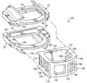
- FIG. 3 ais an exploded view of a modular motion-preserving prosthetic device incorporating the end members of FIG. 2 according to one embodiment of the present disclosure.
- FIG. 3 bis an isometric view of the prosthetic device of FIG. 3 a.
- FIG. 4 ais an exploded view of a modular prosthetic fusion device incorporating the end members of FIG. 2 according to another embodiment of the present disclosure.
- FIG. 4 bis an isometric view of the prosthetic device of FIG. 4 a.
- FIG. 5is a lateral view of a pair of vertebral bodies depicting an intermediate vertebral body removed.
- FIG. 6 ais an isometric view of a stacking member for use in a modular prosthetic device according to one embodiment of the present disclosure.
- FIG. 6 bis an isometric view of the stacking member of FIG. 6 a from a different angle.
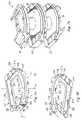
- FIG. 7 ais an exploded view of a modular motion-preserving prosthetic device incorporating the end members of FIGS. 2 a and 2 b and the stacking member of FIGS. 6 a and 6 b according to one embodiment of the present disclosure.
- FIG. 7 bis an isometric view of the prosthetic device of FIG. 7 a.
- FIG. 8 ais an exploded view of a modular prosthetic fusion device incorporating the end members of FIGS. 2 a and 2 b and the stacking member of FIGS. 6 a and 6 b according to another embodiment of the present disclosure.
- FIG. 8 bis an isometric view of the prosthetic device of FIG. 8 a.
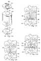
- FIG. 9 ais an exploded view of a modular prosthetic device incorporating the end members of FIGS. 2 a and 2 b and a pair of the stacking members of FIGS. 6 a and 6 b according to another embodiment of the present disclosure.
- FIG. 9 bis an isometric view of the prosthetic device of FIG. 9 a.
- FIG. 10 ais an exploded view of a modular prosthetic device incorporating the end members of FIGS. 2 and 2 b according to another embodiment of the present disclosure.
- FIG. 10 bis an isometric view of the prosthetic device of FIG. 10 a.
- FIG. 11 ais an exploded view of a modular prosthetic device incorporating the end members of FIGS. 2 a and 2 b according to another embodiment of the present disclosure.
- FIG. 11 bis an isometric view of the prosthetic device of FIG. 11 a.
- FIG. 12 ais an exploded view of a modular prosthetic device according to another embodiment of the present disclosure.
- FIG. 12 bis a lateral view depicting the prosthetic device of FIG. 12 a disposed between a pair of vertebral bodies.
- FIG. 12 cis a lateral view of the prosthetic device of FIG. 12 b connected to a verterbral body.
- FIG. 12 dis a lateral view of the prosthetic device of FIG. 12 b connected to a linkage system.
- the anchoring devicefor disposition within an intervertebral space.
- the anchoring deviceincludes first and second end members, the first and second end members cooperating to receive a prosthetic insertion device.
- the first and second end memberseach have a first surface, at least one vertebral-engaging member extending from the first surface, a second surface in an opposed relation to the first surface, and at least one flange extending from the second surface.
- an anchoring devicefor receiving a prosthetic insertion device.
- the anchoring deviceincludes a first end member having a first surface in an opposed relation to a second surface, a pair of vertebral-engaging members extending from the first surface, the vertebral-engaging members being angled towards one another, a pair of flanges extending from the second surface, the flanges being angled towards one another to define a pair of elongated slots, and a pair of cam devices positioned adjacent the elongated slots, the cam devices moveable between a first position and a second position.
- the anchoring devicefurther includes a second end member cooperating with the first end member to receive a prosthetic insertion device, the second end member comprising a first surface in an opposed relation to a second surface, a pair of vertebral-engaging members extending from the first surface, the vertebral-engaging members being angled towards one another, a pair of flanges extending from the second surface, the flanges being angled towards one another to define a pair of elongated slots, and a pair of cam devices positioned adjacent the elongated slots, the cam devices moveable between a first position and a second position.
- an end member for receiving a portion of a prosthetic insertion deviceincludes a first surface, at least one vertebral-engaging member extending from the first surface, a second surface in an opposed relation to the first surface, and at least one flange extending from the second surface, and a locking mechanism for releasably securing a portion of a prosthetic insertion device.
- a modular prosthetic devicein yet another embodiment, includes first and second end members each having at least one receiving portion and at least one locking mechanism positioned adjacent to the receiving portion.
- the modular prosthetic devicefurther includes a prosthetic insertion device having an engaging portion for engaging the at least one receiving portion of the first and second end members, the prosthetic insertion device being adapted to be releasably secured to the first and second end members by the at least one locking mechanism of the first and second end members.
- a stacking memberfor use in forming a modular, stackable prosthetic device.
- the stacking memberincludes a first surface in an opposed relation to a second surface, the first and second surfaces each having at least one flange to define a receiving portion, and a locking mechanism positioned adjacent to the receiving portion, the locking mechanism being movable between a first position and a second position.
- a modular, stackable prosthetic devicein yet another embodiment, includes first and second end members each having at least one receiving portion, a stacking member positioned between the first and second end members, the stacking member having first and second surfaces, and at least one receiving portion defined along each of the first and second surfaces.
- the modular, stackable prosthetic devicefurther includes a first prosthetic insertion device comprising an engaging portion for engaging the at least one receiving portion of the first end member, and an engaging portion for engaging the at least one receiving portion defined along the first surface of the stacking member, and a second prosthetic insertion device comprising an engaging portion for engaging the at least one receiving portion of the second end member, and an engaging portion for engaging the at least one receiving portion defined along the second surface of the stacking member.
- a modular prosthetic devicein yet another embodiment, includes a first implant member having a first articular surface, a second implant member having a second articular surface, and a spacer member positioned between the first and second implant members, the spacer member having a third articular surface cooperating with the first articular surface to permit articulating motion between the spacer member and the first implant member, and a fourth articular surface cooperating with the second articular surface to permit articulating motion between the spacer member and the second implant member.
- a modular prosthetic devicefor insertion into a space created by a vertebrectomy.
- the modular prosthetic deviceincludes a first implant member adapted to engage a first vertebral body and having a first articular surface, a second elongated implant member adapted to engage a second vertebral body and having a second articular surface, the first and second articular surfaces cooperating to permit articulating motion between said first and second implant members.
- the second elongated implant memberspans the space created by the vertebrectomy.
- a method for assembling a prosthetic deviceincludes the steps of providing an anchoring device comprising first and second end members, the first and second end members having slots defined therein, providing a prosthetic insertion device having end portions corresponding to the slots defined in the anchoring device, aligning the end portions of the prosthetic insertion device with the slots of the anchoring device, and inserting the prosthetic insertion device into the anchoring device via the cooperation of the end portions and the slots.
- the present disclosurerelates to modular spinal implants, and more particularly, to modular spinal implants that can be revised according to particular spinal procedures.
- modular spinal implantsthat can be revised according to particular spinal procedures.
- FIG. 1shown therein is a lateral view of a portion of a spinal column 10 , illustrating adjacent upper and lower vertebral bodies V U , V L separated by a space S 1 created by the removal of an intervertebral disc.
- the natural disc that would have been positioned between the two vertebral bodies V U , V Lis typically removed via a discectomy or a similar surgical procedure, the details of which would be known to one of ordinary skill in the art. It is desired to insert a prosthetic device into the space S 1 to restore the structural integrity of the spinal column 10 upon removal of the intervertebral disc.
- an anchoring deviceis generally referred to by the reference numeral 20 .
- the anchoring device 20extends generally along a longitudinal axis L and includes a pair of substantially identical, yet inverted, end members 22 , 22 ′.
- substantially identical componentswill be given the same reference numerals.
- the lower end member 22 ′ as viewed in FIGS. 2 a and 2 b and its componentsare given an apostrophe (“'”) to simplify the following explanation of the anchoring device 20 .
- the end members 22 , 22 ′ of the anchoring device 20may be formed from a wide variety of materials, in one embodiment of the disclosure, the end members 22 , 22 ′ are formed of a cobalt-chrome-molybdenum metallic alloy (ASTM F-799 or F-75). However, in alternative embodiments of the disclosure, the end members 22 , 22 ′ may be formed of other materials such as titanium or stainless steel, a polymeric material such as polyethylene, or any other biocompatible material that would be apparent to one of ordinary skill in the art.
- the end members 22 , 22 ′ of the anchoring device 20are adapted to receive a variety of prosthetic insertion devices for forming a variety of modular prosthetic devices.
- the anchoring device 20may be used in conjunction with a motion-preserving device 30 to form a modular prosthetic joint 32 , which may then be inserted into the space S 1 ( FIG. 1 ) to engage the upper and lower vertebral bodies V U , V L .
- the motion-preserving device 30is configured as a ball and socket device and thus includes a socket component 34 and a ball component 36 .
- a socket component 34 and a ball component 36are contemplated for use with the anchoring device 20 such as devices formed of polymer or hydro gel that can replicate the movement of a healthy disc.
- the socket and ball components 34 and 36may be formed of a variety of materials including, but not limited to, PEEK, stainless steel, UHMWPE, cobalt chrome, zirc coated materials and ceramics.
- the modular prosthetic joint 32provides relative pivotal and rotational movement between the adjacent vertebral bodies to maintain or restore motion substantially similar to the normal bio-mechanical motion provided by a natural intervertebral disc.
- the motion-preserving device 30permits the end members 22 , 22 ′ to pivot relative to one another about a number of axes, including lateral or side-to-side pivotal movement about longitudinal axis L and anterior-posterior pivotal movement about a transverse axis T.
- the motion-preserving device 30permits the end members 22 , 22 ′ to rotate relative to one another about a rotational axis R.
- the modular prosthetic joint 32has been illustrated and described as providing a specific combination of articulating motion, it should be understood that other combinations of articulating movement are also possible, such as, for example, relative translational or linear motion, and such movement is contemplated as falling within the scope of the present disclosure.
- the end member 22includes a pair of fins 40 , 42 longitudinally extending along a substantial portion of an outer surface 44 .
- the fins 40 , 42are provided for engaging an adjacent vertebral body, such as V U in FIG. 1 .
- the fins 40 , 42are angled towards one another and each include a sharp edge 46 , 48 , respectively.
- the fins 40 , 42may be configured in any shape that facilitates the functional demands of the fins such as a tapered or orthogonal (relative to the outer surface 44 ) configuration and that the edges 46 , 48 may be formed on opposite portions of the fins as viewed in FIGS. 2 a – 3 b.
- the fins 40 , 42 and the outer surface 44may be coated with a bone-growth promoting substance, such as, for example, a hydroxyapatite coating formed of calcium phosphate. Additionally, the fins 40 , 42 and the outer surface 44 may be roughened prior to being coated with the bone-growth promoting substance to further enhance bone on-growth. Such surface roughening may be accomplished by way of, for example, acid etching, knurling, application of a bead coating, or other methods of roughening that would occur to one of ordinary skill in the art. Still further, a hole 50 may be formed through the end member 22 in a direction along the rotational axis R to further promote bone-growth between the end member 22 and the adjacent vertebral body V U .
- a bone-growth promoting substancesuch as, for example, a hydroxyapatite coating formed of calcium phosphate.
- the fins 40 , 42 and the outer surface 44may be roughened prior to being coated with the bone-growth promoting substance to further enhance bone
- the end member 22further includes an inner surface 60 ( FIG. 2 b ), which, in one embodiment, is in an opposed relation to the outer surface 44 .
- a pair of angled flanges 62 , 64depend towards one another from the inner surface 60 and extend longitudinally along a substantial portion of the inner surface to define a pair of elongated slots 66 , 68 , respectively.
- the slots 66 , 68may have any number of configurations such as keyway, L, or curved configurations, and thus the flanges 62 , 64 may take any number of shapes to define the slots.
- the slots 66 , 68are open at an anterior portion of the end member 22 (depicted as the front portion of the end member as viewed in FIGS. 2 a and 2 b ) in order to receive corresponding portions of the socket component 34 of the motion preserving device 30 .
- the slots 66 , 68are sealed off at a posterior portion of the end member 22 (depicted as the back portion of the end member as viewed in FIGS. 2 a and 2 b ) via a posterior wall 70 of the end member.
- the posterior wall 70provides a stop against which the socket component 34 abuts upon full insertion into the end member 22 as will be described.
- anterior, posterior and lateralare for purposes of clarification only, and is not intended to limit the modular prosthetic joint 32 (or the additional embodiments described herein) to a specific orientation relative to such anatomical directions.
- the posterior portion of the end member 22may be open and the anterior portion closed, or the open and closed portions may be defined in lateral directions.
- the socket component 34includes a pair of tapered end portions 72 , 74 , which are adapted to fit into the slots 66 , 68 .
- the end portions 72 , 74 of the socket component 34may have any number of configurations so long as the end portions can engage the slots 66 , 68 .
- the end member 22further includes a pair of cam devices 80 , 82 ( FIG. 2 b ), which are positioned adjacent to the slots 66 , 68 , respectively, and aid in securing the socket component 34 to the end member.
- the cam devices 80 , 82each engage a cam slot (one of which is depicted as 88 ) formed in the socket component 34 to retain the socket component 34 to the end member 22 upon insertion therein.
- the cam devices 80 , 82are movable between an open position (cam device 82 in FIG. 2 b ) and a closed position (cam device 80 in FIG.
- an elongated slot 100( FIG. 2 b ) is formed in the cam device 80 such that a tool may engage the slot to actuate the cam device between the open and closed positions.
- cam device 82includes an elongated slot substantially identical to slot 100 .
- the cam devices 80 , 82may be in a frictional engagement with the end member 22 , which allows the cam devices to be maintained in the open and closed positions without regard to gravity.
- cam devices 80 , 82are contemplated for use with the anchoring device 20 such as pressure fits or slot and peg assemblies. It is also understood that no locking mechanism may be necessary and the end member 22 receives a prosthetic insertion device in a frictional engagement.
- the end member 22 ′is substantially similar to the end member 22 and thus includes a pair of fins 40 ′, 42 ′ having a pair of sharp edges 46 ′, 48 ′, an outer surface 44 ′, a hole 50 ′, an inner surface 60 ′, a pair of angled flanges 62 ′, 64 ′ defining a pair of elongated slots 66 ′, 68 ′, a posterior wall 70 ′, a pair of cam devices 80 ′, 82 ′, a pair of access holes 96 ′, 98 ′, and an elongated slot (one of which is shown as 100 ′ in FIG. 2 a ) formed in each cam device.
- the end member 22 ′is adapted to receive and retain the ball component 36 of the motion-preserving device 30 in substantially the same manner as the end member 22 receives and retains the socket component 34 described above.
- the ball component 36includes a pair of tapered end portions 102 , 104 , which are adapted to fit into the slots 66 ′, 68 ′. It is understood that the socket and ball components 34 , 36 are interchangeable between the end members 22 , 22 ′.
- the socket component 34includes a recess 110 .
- the recess 110has a concave shape, and is configured as a spherical-shaped socket.
- other configurations of the recess 110are also contemplated, such as, for example, cylindrical, elliptical or other arcuate configurations or possibly non-arcuate configurations.
- the recess 110is depicted as being formed in a raised portion of the socket component 34 , it is understood that the socket component may be of sufficient thickness to have a recess formed therein without need for the raised portion.
- the remaining portion of the socket component 34can be tapered or otherwise configured to facilitate the insertion of the socket component into the end member 22 .
- the ball component 36includes a projection 112 having a convex shape, which may be configured as a spherical-shaped ball (half of which is shown). It should be understood that other configurations of the projection 112 are also contemplated, such as, for example, cylindrical, elliptical or other arcuate configurations or possibly non-arcuate configurations. It should also be understood that the remaining portion of the ball component 36 may take on planar or non-planar configurations, such as, for example, a tapered configuration extending from the projection 112 to the end portions 102 , 104 .
- the convex projection 112is illustrated as having a generally smooth, uninterrupted surface, it should be understood that a surface depression or cavity may be defined along a portion of the projection to provide a means for clearing out matter, such as particulate debris, that is disposed between the abutting socket and ball components 34 , 36 .
- the convex surface of the recess 110may alternatively define a generally smooth, uninterrupted surface.
- each of the convex projection 112 and the concave recess 110may define a surface depression to facilitate removal of particulate matter disposed between the abutting ball and socket components 34 , 36 .
- the convex projection 112may have a generally smooth, uninterrupted surface and the concave recess 110 may include a surface depression or cavity defined along the surface thereof.
- the modular prosthetic joint 32may be assembled by preparing the end member 22 to receive the socket component 34 by actuating the cam devices 80 , 82 to an open position.
- the end portions 72 , 74 of the socket component 34are then aligned with the slots 66 , 68 of the end member 22 and the socket component is inserted into the end member to the point of making contact with the posterior wall 70 .
- the cam devices 80 , 82are then actuated via a tool (not shown) to a closed position, thereby securing the socket component 34 to the end member 22 .
- the end member 22 ′is prepared for receiving the ball component 36 by actuating the cam devices 80 ′, 82 ′ to an open position.
- the end portions 102 , 104 of the ball component 36are then aligned with the slots 66 ′, 68 ′ of the end member 22 ′ and the ball component is inserted into the end member to the point of making contact with the posterior wall 70 ′.
- the cam devices 80 ′, 82 ′are then actuated via a tool (not shown) to a closed position, thereby securing the ball component 36 to the end member 22 ′.
- the above-described assemblage processesmay take place prior to or after insertion of the end members 22 , 22 ′ into the vertebral bodies V U , V L ( FIG. 1 ). Furthermore, cuts can be formed in the vertebral bodies V U , V L to receive the fins 40 , 42 and 40 ′, 42 ′ of the end members 22 , 22 ′, respectively, or the fins themselves, via the edges 46 , 48 and 46 ′, 48 ′, can be used to cut into the vertebral bodies.
- modular prosthetic joint 32may be inserted into the disc space S 1 between the vertebral bodies V U , V L from a variety of approaches including, but not limited to, the anterior, oblique and lateral approaches.
- prosthetic insertion devicesother than the motion-preserving device 30 can be used with the anchoring device 20 .
- the modular prosthetic joint 32can be revised into a modular prosthetic fusion device without having to discard, or otherwise replace, the anchoring device 20 .
- a modular prosthetic fusion device 120may be inserted into the space S 1 between the vertebral bodies V U , V L ( FIG. 1 ) to promote fusion therebetween.
- the modular prosthetic fusion device 120includes a fusion cage 122 , which is insertable into the end members 22 , 22 ′. It is understood that a variety of other fusion members are contemplated for use with the end members 22 , 22 ′ other than the fusion cage 122 .
- the fusion cage 122may be formed of a variety of materials including, but not limited to, PEEK, stainless steel, UHMWPE, cobalt chrome, zirc coated materials and ceramics.
- the fusion cage 122is a unitary structure that includes a pair of lateral walls 124 , 126 , an anterior wall 128 and a posterior wall 130 , all of which define an opening 132 through the fusion cage 122 along a rotational axis R.
- the opening 132promotes fusing bone growth between the vertebral bodies V U , V L ( FIG. 1 ).
- a plurality of apertures 134 , 136 , 138 , 140 , 142 , 146maybe formed through the lateral 124 , 126 and anterior 128 walls to further encourage bone growth.
- the fusion cage 122may be coated with a bone-growth promoting substance, such as, for example, a hydroxyapatite coating formed of calcium phosphate. Additionally, the fusion cage 122 may be roughened prior to being coated with the bone-growth promoting substance to further enhance bone on-growth. Such surface roughening may be accomplished by way of, for example, acid etching, knurling, application of a bead coating, or other methods of roughening that would occur to one of ordinary skill in the art.
- a bone-growth promoting substancesuch as, for example, a hydroxyapatite coating formed of calcium phosphate.
- the fusion cage 122may be roughened prior to being coated with the bone-growth promoting substance to further enhance bone on-growth.
- Such surface rougheningmay be accomplished by way of, for example, acid etching, knurling, application of a bead coating, or other methods of roughening that would occur to one of ordinary skill in the art.
- a tapered extension 150 , 152 , 154 , 156extends longitudinally along a substantial portion of each edge of each lateral wall 124 , 126 .
- the tapered extensions 150 , 154are adapted to fit into the slots 66 , 68 of the end member 22 and the tapered extensions 152 , 156 are adapted to fit into the slots 66 ′, 68 ′ of end member 22 ′.
- the tapered extensions 150 , 152 , 154 , 156 and the slots 66 , 66 ′, 68 , 68 ′may have any number of configurations so long as the slots can receive the fusion cage 122 in a corresponding engagement.
- the modular prosthetic fusion device 120may be assembled by preparing the end members 22 and 22 ′ to receive the fusion cage 122 by actuating the cam devices 80 , 80 ′, 82 , 82 ′ to an open position.
- the tapered extensions 150 , 152 , 154 , 156 of the fusion cage 122are then aligned with the slots 66 , 66 ′, 68 , 68 ′ of the end members 22 , 22 ′ and the fusion cage 122 is inserted into the end members to the point of making contact with the posterior walls 70 , 70 ′.
- the cam devices 80 , 80 ′, 82 , 82 ′are then actuated via a tool (not shown) to a closed position, thereby securing the fusion cage 122 to the end members 22 , 22 ′.
- the motion-preserving device 30may be disposed within the anchoring device prior to insertion of the fusion cage 122 .
- the motion-preserving device 30can be removed from the anchoring device 20 by simply opening the cam devices 80 , 80 ′, 82 , 82 ′ and extracting the socket and ball components 34 , 36 in an anterior direction.
- the anchoring device 20is contemplated for use not only with modular prosthetic devices for insertion between adjacent vertebral bodies V U , V L ( FIG. 1 ) after discectomy, but also for use in stabilizing regions of the spine in the aftermath of more complex procedures such as corpectomy and vertebrectomy procedures.
- FIG. 5shown therein is a lateral view of a portion of a spinal column 200 , illustrating a pair of vertebral bodies V 1 , V 2 separated by a space S 2 created by the removal of a pair of intervertebral discs and an intervertebral body that had been positioned between the vertebral bodies V 1 , V 2 .
- the natural disc and vertebral body that would have been positioned between the two vertebral bodies V 1 , V 2is typically removed via a corpectomy or vertebrectomy or a similar surgical procedure, the details of which would be known to one of ordinary skill in the art. It is desired to insert a prosthetic device into the space S 2 to restore the structural integrity of the spinal column 200 upon removal of the intervertebral discs and vertebral body.
- a stacking member 202may be used in conjunction with the anchoring device 20 to form a modular stackable prosthetic joint 204 ( FIGS. 7 a and 7 b ), which can be inserted into the space S 2 ( FIG. 5 ).
- the upper portion of the stacking member 202(as viewed in FIGS. 6 a and 6 b ) is substantially identical to the lower portion of the stacking member except for the inverted relationship between the upper and lower portions, and as such, the components of the lower portion of the stacking member are given an apostrophe (“'”) to simplify the following explanation of the stacking member.
- the stacking member 202includes an upper surface 206 (as viewed in FIGS.
- a pair of angled flanges 210 , 212depend towards one another from the upper surface 206 and extend longitudinally along a substantial portion of the upper surface 206 to define a pair of elongated slots 214 , 216 , respectively.
- the slots 214 , 216may have any number of configurations such as keyway, L, or curved configurations, and thus the flanges 210 , 212 may take any number of shapes to define the slots.
- the slots 214 , 216are open at an anterior portion of the end member (as viewed in FIGS. 6 a and 6 b ) in order to receive corresponding portions of a variety of prosthetic insertion devices as will be described.
- the slots 214 , 216are sealed off at a posterior portion of the end member 22 (as viewed in FIGS. 6 a and 6 b ) via a posterior wall 218 of the stacking member 202 .
- the posterior wall 218provides a stop against which a prosthetic insertion device abuts upon full insertion into the upper portion of the stacking member (as viewed in FIGS. 6 a and 6 b ).
- the stacking member 202further includes a pair of cam devices 220 , 222 , which are positioned adjacent to the slots 214 , 216 , respectively, and aid in securing a prosthetic device to the stacking member.
- the cam devices 220 , 222each engage a cam slot (not shown) formed in a prosthetic insertion device to be inserted into the upper portion of the stacking member 202 .
- the cam devices 220 , 222are movable between an open position ( 220 in FIG. 6 a ) and a closed position ( 222 in FIG. 6 a ) via a tool (not depicted), which is insertable through a pair of access holes 232 , 234 , respectively.
- a tool(not depicted), which is insertable through a pair of access holes 232 , 234 , respectively.
- an elongated slot 236is formed in the cam device 220 such that a tool may engage the slot to actuate the cam device between the open and closed positions.
- the cam device 222includes an elongated slot substantially identical to slot 236 .
- cam devices 220 , 222may be in a frictional engagement with the stacking member 202 , which allows the cam devices to be maintained in the open and closed positions without regard to gravity. It is understood that other locking mechanisms other than the depicted cam devices 220 , 222 are contemplated for use with the stacking member 202 such as pressure fits or slot and peg assemblies. It is also understood that no locking mechanism may be necessary and the stacking member 202 receives a prosthetic insertion device in a frictional engagement.
- the lower portion of the stacking member 202is substantially similar to the upper portion of the stacking member (as viewed in FIGS. 6 a and 6 b ) and thus includes a lower surface 206 ′ (corresponding to upper surface 206 ), a pair of angled flanges 210 ′, 212 ′ defining a pair of elongated slots 214 ′, 216 ′, a pair of cam devices 220 ′, 222 ′, a pair of access holes 232 ′, 234 ′, and an elongated slot (not shown) formed in each cam device.
- the upper and lower portions of the stacking member 202share the same posterior wall 218 .
- a hole 240may be formed through the stacking member 202 to define an opening through which bone growth may occur as will be described.
- a pair of motion-preserving devices substantially identical to the motion-preserving device 30may be used in conjunction with the anchoring device 20 and the stacking member 202 to form the modular stackable prosthetic joint 204 .
- the modular stackable prosthetic joint 204may be assembled by aligning the end portions 72 , 74 of the upper motion-preserving device 30 (as viewed in FIGS. 7 a and 7 b ) with the slots 66 , 68 of the upper end member 22 and aligning the end portions 102 , 104 with the slots 214 , 216 of the stacking member 202 .
- the upper motion-preserving device 30may then be inserted into the upper end member 22 and the stacking member 202 .
- the lower motion-preserving device 30(as viewed in FIGS. 7 a and 7 b ) may be assembled into the modular stackable prosthetic joint 204 by aligning the end portions 72 , 74 of the lower motion-preserving device with the slots 214 ′, 216 ′ of the stacking member 202 and aligning the end portions 102 , 104 with the slots 66 ′, 68 ′ of the lower end member 22 ′ (as viewed in FIGS. 7 a and 7 b ). The lower motion-preserving device 30 may then be inserted into the stacking member 202 and the lower end member 22 ′ to complete the assembly of the modular stackable prosthetic joint 204 .
- the modular stackable prosthetic joint 204can be modified into a variety of other modular stackable prosthetic devices.
- the motion-preserving devices 30 of FIGS. 7 a and 7 bcan be replaced with a pair of fusion cages substantially similar to the fusion cage 122 of FIGS. 4 a and 4 b .
- the modular stackable prosthetic joint 204 of FIGS. 7 a and 7 bcan be revised into a modular stackable prosthetic fusion device 250 .
- a modular stackable prosthetic deviceis generally referred to by the reference numeral 300 and includes a pair of motion-preserving devices substantially similar to the motion-preserving device 30 , a fusion cage substantially similar to the fusion cage 122 , a pair of stacking members 202 disposed between the fusion cage 122 and the motion-preserving devices 30 and a pair of end members 22 , 22 ′.
- any combination of motion-preserving devices or fusion devices, or any other type insertion devicesis contemplated as being disposed between the end members 22 , 22 ′ along with any number of stacking members 202 to provide a revisable stackable prosthetic device.
- the stacking member/members 202may be removed, yet the anchoring device 20 is still adaptable for use in a space such as space S 2 ( FIG. 5 ).
- an elongated fusion cage 308may be inserted between the end members 22 , 22 ′ to form an alternative modular prosthetic fusion device 310 such that fusion between V 1 , V 2 ( FIG. 5 ) can be effected.
- the fusion cage 308may be formed of a variety of materials including, but not limited to, PEEK, stainless steel, UHMWPE, cobalt chrome, zirc coated materials and ceramics.
- the fusion cage 308is a unitary structure that includes a pair of elongated lateral walls 312 , 314 , an elongated anterior wall 316 and an elongated posterior wall 318 , all of which define an opening 320 through the fusion cage 308 along a rotational axis R.
- the opening 320promotes fusing bone growth between the vertebral bodies V 1 , V 2 ( FIG. 5 ).
- a plurality of apertures 322 , 324 , 326 , 328 , 330 , 332may be formed through the lateral 312 , 314 and anterior 316 walls to further encourage bone growth.
- the fusion cage 308may be coated with a bone-growth promoting substance, such as, for example, a hydroxyapatite coating formed of calcium phosphate. Additionally, the fusion cage 308 may be roughened prior to being coated with the bone-growth promoting substance to further enhance bone on-growth. Such surface roughening may be accomplished by way of, for example, acid etching, knurling, application of a bead coating, or other methods of roughening that would occur to one of ordinary skill in the art.
- a tapered extension 340 , 342 , 344 , 346extends longitudinally along a substantial portion of each edge of each lateral wall 312 , 314 .
- the tapered extensions 340 , 344are adapted to fit into the slots 66 , 68 of the end member 22 and the tapered extensions 342 , 346 are adapted to fit into the slots 66 ′, 68 ′ of end member 22 ′.
- the tapered extensions 340 , 342 , 344 , 346 and the slots 66 , 66 ′, 68 , 68 ′may have any number of configurations so long as the slots can receive the fusion cage 308 in a corresponding engagement.
- the modular prosthetic fusion device 310may be assembled by preparing the end members 22 and 22 ′ to receive the fusion cage 308 by actuating the cam devices 80 , 80 ′, 82 , 82 ′ to an open position.
- the tapered extensions 340 , 342 , 344 , 346 of the fusion cage 308are then aligned with the slots 66 , 66 ′, 68 , 68 ′ of the end members 22 , 22 ′ and the fusion cage 308 is inserted into the end members to the point of making contact with the posterior walls 70 , 70 ′.
- the cam devices 80 , 80 ′, 82 , 82 ′are then actuated via a tool (not shown) to a closed position, thereby securing the fusion cage 308 to the end members 22 , 22 ′.
- a modular prosthetic device incorporating the anchoring device 20may be revised to include a corpectomy device and a motion-preserving component.
- an alternative modular prosthetic deviceis generally referred to by reference numeral 350 and includes an elongated solid device 352 and a ball component substantially similar to the ball component 36 disposed between the end members 22 , 22 ′.
- the solid device 352includes a recess 354 formed in a lower portion (as viewed in FIGS. 11 a and 11 b ) thereof such that the solid device may receive the corresponding projection 112 of the ball component 36 .
- the solid device 352further includes a pair of tapered extensions 360 , 362 for fitting to the slots 66 , 68 of end member 22 .
- the tapered extensions 360 , 362 and the slots 66 , 68may have any number of configurations so long as the slots can receive the solid device 352 in a corresponding engagement.
- the modular prosthetic device 350may be assembled by preparing the end member 22 to receive the solid device 352 by actuating the cam devices (not shown) to an open position.
- the tapered extensions 360 , 362 of the solid device 352are then aligned with the slots 66 , 68 of the end member 22 and the solid device 352 is inserted into the end member to the point of making contact with the posterior wall 70 .
- the cam devices (not shown)are then actuated via a tool (not shown) to a closed position, thereby securing the solid device 352 to the end member 22 .
- the ball component 36in the embodiment of FIGS.
- the modular prosthetic device 350provides for articulating motion at only one end of the space S 2 ( FIG. 5 ), which may provide a relatively more stable arrangement.
- the anchoring device 20 of the previous embodimentsmay be replaced with socket and ball components 400 , 402 that each include a keel 404 , 406 , respectively, for engaging the vertebral bodies V 1 , V 2 ( FIG. 5 ), respectively.
- the socket and ball components 400 , 402are substantially similar to the socket and ball components 34 , 36 as described with respect to FIGS. 3 a and 3 b .
- Such socket and ball components 400 , 402are described more fully in U.S. Provisional Application No. 60/446,963 filed on Feb. 12, 2003, which is herein incorporated by reference for all legitimate purposes.
- a spacer device 410is provided between the socket and ball components 400 , 402 and includes a projection 412 corresponding to a recess 414 formed in the socket component 400 .
- the spacer device 410also includes a recess 416 corresponding to projection 418 extending from the ball component 402 .
- the socket and ball components 400 , 402are shown laterally engaged with the vertebral bodies V 1 , V 2 , respectively, and the spacer device 410 is shown engaged with the socket and ball components. It is understood that the socket and ball components 400 , 402 may be inserted into the vertebral bodies V 1 , V 2 from a variety of approaches other than the lateral approach, such as the anterior, transforaminal or anterior-oblique approaches. As is also illustrated, the spacer device 410 is positioned adjacent to a floating arch 420 , the floating arch being the portion of vertebral body that remains after a vertebrectomy. The length of the spacer device 410 allows the spacer device to span between the socket and ball components 400 , 402 , thereby allowing articulating motion at both vertebral bodies V 1 , V 2 .
- either of the socket and ball components 400 , 402can be secured to an adjacent vertebral bone, such as an arch 422 , via a linkage 424 .
- the linkage 424may also be secured to a posterior plate 428 , which, is secured to another linkage 430 .
- the linkage 430can be configured to engage the spacer device 410 .
- linkages 424 and 430 and the posterior plate 428can be formed of any bio-compatible material and that the various connections between the linkages and the posterior plate and between the linkages and the prosthetic devices can be accomplished by way of threaded, slotted or any other type of conventional connection means.
- fixation systemsare contemplated for use with the embodiments of FIGS. 12 c and 12 d , such as Antares, Z-Plate and CD Horizon fixation systems.
- stabilizationcan be achieved by removing the spacer device 410 and elongating either of the socket and ball components 400 , 402 such that the socket and ball components engage one another in an articulating arrangement.
- motionwould again only be provided at one of the vertebral bodies V 1 , V 2 , which would result in a relatively stable arrangement.
- the spacer device 410may be provided with a socket and ball arrangement to provide a third articulating segment between the vertebral bodies V 1 , V 2 .
- the present disclosurehas been described relative to several preferred embodiments. Improvements or modifications that become apparent to persons of ordinary skill in the art after reading this disclosure are deemed within the spirit and scope of the application.
- the various prosthetic insertion devices described abovecan be altered according to specific conditions such as lordosis and kyphosis, and thus it is contemplated that the above embodiments can be adapted for implementation into patients having varying spinal orientations. Moreoever, other prosthetic insertion devices are contemplated for use with the anchoring device 20 and the stacking member 202 other than those prosthetic insertion devices illustrated and described above.
Landscapes
- Health & Medical Sciences (AREA)
- Engineering & Computer Science (AREA)
- Biomedical Technology (AREA)
- Orthopedic Medicine & Surgery (AREA)
- Neurology (AREA)
- Heart & Thoracic Surgery (AREA)
- Oral & Maxillofacial Surgery (AREA)
- Transplantation (AREA)
- Cardiology (AREA)
- Vascular Medicine (AREA)
- Life Sciences & Earth Sciences (AREA)
- Animal Behavior & Ethology (AREA)
- General Health & Medical Sciences (AREA)
- Public Health (AREA)
- Veterinary Medicine (AREA)
- Prostheses (AREA)
Abstract
Description
Claims (27)
Priority Applications (8)
| Application Number | Priority Date | Filing Date | Title |
|---|---|---|---|
| US10/662,928US7235101B2 (en) | 2003-09-15 | 2003-09-15 | Revisable prosthetic device |
| EP04784063AEP1673045A2 (en) | 2003-09-15 | 2004-09-15 | Revisable prosthetic device |
| AU2004273860AAU2004273860A1 (en) | 2003-09-15 | 2004-09-15 | Revisable prosthetic device |
| JP2006526410AJP2007505652A (en) | 2003-09-15 | 2004-09-15 | Adhering device placed in the intervertebral space |
| PCT/US2004/030077WO2005027800A2 (en) | 2003-09-15 | 2004-09-15 | Revisable prosthetic device |
| CA002538566ACA2538566A1 (en) | 2003-09-15 | 2004-09-15 | Revisable prosthetic device |
| US11/097,553US7938858B2 (en) | 2003-09-15 | 2005-04-01 | Spinal implant system |
| US11/768,149US7682397B2 (en) | 2003-02-12 | 2007-06-25 | Revisable prosthetic device |
Applications Claiming Priority (1)
| Application Number | Priority Date | Filing Date | Title |
|---|---|---|---|
| US10/662,928US7235101B2 (en) | 2003-09-15 | 2003-09-15 | Revisable prosthetic device |
Related Child Applications (2)
| Application Number | Title | Priority Date | Filing Date |
|---|---|---|---|
| US11/097,553Continuation-In-PartUS7938858B2 (en) | 2003-09-15 | 2005-04-01 | Spinal implant system |
| US11/768,149DivisionUS7682397B2 (en) | 2003-02-12 | 2007-06-25 | Revisable prosthetic device |
Publications (2)
| Publication Number | Publication Date |
|---|---|
| US20050060034A1 US20050060034A1 (en) | 2005-03-17 |
| US7235101B2true US7235101B2 (en) | 2007-06-26 |
Family
ID=34274247
Family Applications (2)
| Application Number | Title | Priority Date | Filing Date |
|---|---|---|---|
| US10/662,928Expired - Fee RelatedUS7235101B2 (en) | 2003-02-12 | 2003-09-15 | Revisable prosthetic device |
| US11/768,149Expired - LifetimeUS7682397B2 (en) | 2003-02-12 | 2007-06-25 | Revisable prosthetic device |
Family Applications After (1)
| Application Number | Title | Priority Date | Filing Date |
|---|---|---|---|
| US11/768,149Expired - LifetimeUS7682397B2 (en) | 2003-02-12 | 2007-06-25 | Revisable prosthetic device |
Country Status (6)
| Country | Link |
|---|---|
| US (2) | US7235101B2 (en) |
| EP (1) | EP1673045A2 (en) |
| JP (1) | JP2007505652A (en) |
| AU (1) | AU2004273860A1 (en) |
| CA (1) | CA2538566A1 (en) |
| WO (1) | WO2005027800A2 (en) |
Cited By (102)
| Publication number | Priority date | Publication date | Assignee | Title |
|---|---|---|---|---|
| US20050149193A1 (en)* | 2003-11-20 | 2005-07-07 | St. Francis Medical Technology, Inc. | Intervertebral body fusion cage with keels and implantation methods |
| US20050251260A1 (en)* | 2002-08-15 | 2005-11-10 | David Gerber | Controlled artificial intervertebral disc implant |
| US20060004453A1 (en)* | 2004-06-30 | 2006-01-05 | Depuy Spine, Inc. | Ceramic disc prosthesis |
| US20060058880A1 (en)* | 2004-08-25 | 2006-03-16 | Steve Wysocki | Expandable interbody fusion device |
| US20070088441A1 (en)* | 2004-06-30 | 2007-04-19 | Synergy Disc Replacement, Inc. | Artificial Spinal Disc |
| US20070093900A1 (en)* | 2005-09-26 | 2007-04-26 | Williams Lytton A | Modular articulating and fusion spinal disc implant system |
| US20070100212A1 (en)* | 2004-10-08 | 2007-05-03 | Nuvasive, Inc. | Surgical access system and related methods |
| US20070100347A1 (en)* | 2005-10-31 | 2007-05-03 | Stad Shawn D | Arthroplasty revision device and method |
| US20070213826A1 (en)* | 2006-03-08 | 2007-09-13 | Seaspine, Inc. | Intervertebral spacer and insertion tool providing multiple angles of insertion |
| US20070233107A1 (en)* | 2006-02-27 | 2007-10-04 | Zielinski Steven C | Method and apparatus for lateral reduction and fusion of the spine |
| US20080015693A1 (en)* | 2004-05-27 | 2008-01-17 | Regis Le Couedic | Spinal Arthroplasty System |
| US20080058939A1 (en)* | 2006-08-25 | 2008-03-06 | Warsaw Orthopedic, Inc. | Revision Spacer |
| US20080071375A1 (en)* | 2005-10-10 | 2008-03-20 | Carver Donna J | Artificial spinal disc replacement system and method |
| US20080133013A1 (en)* | 2004-06-30 | 2008-06-05 | Synergy Disc Replacement, Inc. | Artificial Spinal Disc |
| US20080215156A1 (en)* | 2004-06-30 | 2008-09-04 | Synergy Disc Replacement | Joint Prostheses |
| US20090054986A1 (en)* | 2005-05-02 | 2009-02-26 | Cordaro Nicholas M | Motion restoring intervertebral device |
| US20090076616A1 (en)* | 2004-06-30 | 2009-03-19 | Synergy Disc | Systems and Methods for Vertebral Disc Replacement |
| US20090082868A1 (en)* | 2005-05-02 | 2009-03-26 | Cordaro Nicholas M | Prosthesis for restoring motion in an appendage or spinal joint and an intervertebral spacer |
| US20090105835A1 (en)* | 2007-10-22 | 2009-04-23 | Spinalmotion, Inc. | Vertebral Body Replacement and Method for Spanning a Space Formed upon Removal of a Vertebral Body |
| US20090192618A1 (en)* | 2008-01-30 | 2009-07-30 | Zielinski Steven C | Artificial spinal disk |
| US7585325B2 (en)* | 2004-06-16 | 2009-09-08 | Aesculap Ag | Intervertebral implant |
| US7641698B1 (en)* | 2004-06-04 | 2010-01-05 | Biomet Manufacturing Corp. | Modular hip joint implant |
| US20100204737A1 (en)* | 2009-02-11 | 2010-08-12 | IMDS, Inc. | Intervertebral implant with integrated fixation |
| US20100280617A1 (en)* | 2007-01-12 | 2010-11-04 | Synthes Usa, Llc | Modular intervertebral implant |
| US7832409B2 (en) | 2003-05-06 | 2010-11-16 | Aesculap Implant Systems, Llc | Method of inserting an artificial intervertebral disc |
| US20110087331A1 (en)* | 2008-06-05 | 2011-04-14 | Synthes Usa, Llc | Articulating disc implant |
| US20110172773A1 (en)* | 2008-06-05 | 2011-07-14 | Marc Reichen | Articulating disc implant |
| US20110218627A1 (en)* | 2010-03-03 | 2011-09-08 | Warsaw Orthopedic, Inc. | System and method for replacing at least a portion of a vertebral body |
| US20110288645A1 (en)* | 2010-05-21 | 2011-11-24 | Warsaw Orthopedic, Inc. | Intervertebral prosthetic systems, devices, and associated methods |
| US20120265306A1 (en)* | 2011-04-14 | 2012-10-18 | Warsaw Orthopedic, Inc. | Spinal implant with attachable bone securing componet |
| US20130006357A1 (en)* | 2008-11-14 | 2013-01-03 | David Krueger | Spinal fusion device |
| US8409290B2 (en) | 2006-03-08 | 2013-04-02 | Seaspine, Inc. | Interbody device for spinal applications |
| US8808377B2 (en) | 2010-01-13 | 2014-08-19 | Jcbd, Llc | Sacroiliac joint fixation system |
| US8945228B2 (en) | 2012-11-15 | 2015-02-03 | DePuy Synthes Products, LLC | Endplate for a vertebral implant |
| US9033993B2 (en) | 2009-11-03 | 2015-05-19 | Howmedica Osteonics Corp. | Intervertebral implant with integrated fixation |
| US9084683B2 (en) | 2011-01-07 | 2015-07-21 | Pbn Spinal Implants, Llc | Spinal implant system and method |
| US20150328007A1 (en)* | 2014-05-15 | 2015-11-19 | Globus Medical, Inc | Standalone Interbody Implants |
| US9254130B2 (en) | 2011-11-01 | 2016-02-09 | Hyun Bae | Blade anchor systems for bone fusion |
| US9295562B2 (en) | 2008-01-17 | 2016-03-29 | DePuy Synthes Products, Inc. | Expandable intervertebral implant and associated method of manufacturing the same |
| US9320615B2 (en) | 2010-06-29 | 2016-04-26 | DePuy Synthes Products, Inc. | Distractible intervertebral implant |
| US9333090B2 (en) | 2010-01-13 | 2016-05-10 | Jcbd, Llc | Systems for and methods of fusing a sacroiliac joint |
| US9381045B2 (en) | 2010-01-13 | 2016-07-05 | Jcbd, Llc | Sacroiliac joint implant and sacroiliac joint instrument for fusing a sacroiliac joint |
| US9402737B2 (en) | 2007-06-26 | 2016-08-02 | DePuy Synthes Products, Inc. | Highly lordosed fusion cage |
| US9414934B2 (en) | 2008-04-05 | 2016-08-16 | DePuy Synthes Products, Inc. | Expandable intervertebral implant |
| US9421109B2 (en) | 2010-01-13 | 2016-08-23 | Jcbd, Llc | Systems and methods of fusing a sacroiliac joint |
| US9480511B2 (en) | 2009-12-17 | 2016-11-01 | Engage Medical Holdings, Llc | Blade fixation for ankle fusion and arthroplasty |
| US9510872B2 (en) | 2013-03-15 | 2016-12-06 | Jcbd, Llc | Spinal stabilization system |
| US9526620B2 (en) | 2009-03-30 | 2016-12-27 | DePuy Synthes Products, Inc. | Zero profile spinal fusion cage |
| US9554909B2 (en) | 2012-07-20 | 2017-01-31 | Jcbd, Llc | Orthopedic anchoring system and methods |
| US9561117B2 (en) | 2012-07-26 | 2017-02-07 | DePuy Synthes Products, Inc. | Expandable implant |
| US9700425B1 (en)* | 2011-03-20 | 2017-07-11 | Nuvasive, Inc. | Vertebral body replacement and insertion methods |
| US9700356B2 (en) | 2013-07-30 | 2017-07-11 | Jcbd, Llc | Systems for and methods of fusing a sacroiliac joint |
| US9700434B2 (en) | 2009-08-10 | 2017-07-11 | Howmedica Osteonics Corp. | Intervertebral implant with integrated fixation |
| US9717539B2 (en) | 2013-07-30 | 2017-08-01 | Jcbd, Llc | Implants, systems, and methods for fusing a sacroiliac joint |
| US9717601B2 (en) | 2013-02-28 | 2017-08-01 | DePuy Synthes Products, Inc. | Expandable intervertebral implant, system, kit and method |
| US9724207B2 (en) | 2003-02-14 | 2017-08-08 | DePuy Synthes Products, Inc. | In-situ formed intervertebral fusion device and method |
| US9750552B2 (en) | 2009-07-06 | 2017-09-05 | DePuy Synthes Products, Inc. | Expandable fixation assemblies |
| US9788961B2 (en) | 2010-01-13 | 2017-10-17 | Jcbd, Llc | Sacroiliac joint implant system |
| US9801546B2 (en) | 2014-05-27 | 2017-10-31 | Jcbd, Llc | Systems for and methods of diagnosing and treating a sacroiliac joint disorder |
| US9826986B2 (en) | 2013-07-30 | 2017-11-28 | Jcbd, Llc | Systems for and methods of preparing a sacroiliac joint for fusion |
| US9833334B2 (en) | 2010-06-24 | 2017-12-05 | DePuy Synthes Products, Inc. | Enhanced cage insertion assembly |
| US20170354511A1 (en)* | 2016-06-10 | 2017-12-14 | Globus Medical, Inc. | Vertebral implants and attachment assemblies |
| US9913727B2 (en) | 2015-07-02 | 2018-03-13 | Medos International Sarl | Expandable implant |
| US9925051B2 (en) | 2010-12-16 | 2018-03-27 | Engage Medical Holdings, Llc | Arthroplasty systems and methods |
| US20180092754A1 (en)* | 2016-10-04 | 2018-04-05 | Medyssey Co., Ltd. | Spinal complex cage |
| US9949769B2 (en) | 2004-03-06 | 2018-04-24 | DePuy Synthes Products, Inc. | Dynamized interspinal implant |
| US9968460B2 (en) | 2013-03-15 | 2018-05-15 | Medsmart Innovation Inc. | Dynamic spinal segment replacement |
| US9993349B2 (en) | 2002-06-27 | 2018-06-12 | DePuy Synthes Products, Inc. | Intervertebral disc |
| US10159582B2 (en) | 2011-09-16 | 2018-12-25 | DePuy Synthes Products, Inc. | Removable, bone-securing cover plate for intervertebral fusion cage |
| US10182923B2 (en) | 2015-01-14 | 2019-01-22 | Stryker European Holdings I, Llc | Spinal implant with porous and solid surfaces |
| US10238382B2 (en) | 2012-03-26 | 2019-03-26 | Engage Medical Holdings, Llc | Blade anchor for foot and ankle |
| US10245087B2 (en) | 2013-03-15 | 2019-04-02 | Jcbd, Llc | Systems and methods for fusing a sacroiliac joint and anchoring an orthopedic appliance |
| US10369015B2 (en) | 2010-09-23 | 2019-08-06 | DePuy Synthes Products, Inc. | Implant inserter having a laterally-extending dovetail engagement feature |
| US10390963B2 (en) | 2006-12-07 | 2019-08-27 | DePuy Synthes Products, Inc. | Intervertebral implant |
| US10390955B2 (en) | 2016-09-22 | 2019-08-27 | Engage Medical Holdings, Llc | Bone implants |
| US10398563B2 (en) | 2017-05-08 | 2019-09-03 | Medos International Sarl | Expandable cage |
| US10433974B2 (en) | 2003-06-30 | 2019-10-08 | DePuy Synthes Products, Inc. | Intervertebral implant with conformable endplate |
| US10456272B2 (en) | 2017-03-03 | 2019-10-29 | Engage Uni Llc | Unicompartmental knee arthroplasty |
| US10500062B2 (en) | 2009-12-10 | 2019-12-10 | DePuy Synthes Products, Inc. | Bellows-like expandable interbody fusion cage |
| US10537666B2 (en) | 2015-05-18 | 2020-01-21 | Stryker European Holdings I, Llc | Partially resorbable implants and methods |
| US10537436B2 (en) | 2016-11-01 | 2020-01-21 | DePuy Synthes Products, Inc. | Curved expandable cage |
| US10603055B2 (en) | 2017-09-15 | 2020-03-31 | Jcbd, Llc | Systems for and methods of preparing and fusing a sacroiliac joint |
| US10835388B2 (en) | 2017-09-20 | 2020-11-17 | Stryker European Operations Holdings Llc | Spinal implants |
| US10888433B2 (en) | 2016-12-14 | 2021-01-12 | DePuy Synthes Products, Inc. | Intervertebral implant inserter and related methods |
| US20210030558A1 (en)* | 2008-02-29 | 2021-02-04 | Nuvasive, Inc. | Implants and methods for spinal fusion |
| US10940016B2 (en) | 2017-07-05 | 2021-03-09 | Medos International Sarl | Expandable intervertebral fusion cage |
| US20210401581A1 (en)* | 2010-07-27 | 2021-12-30 | Tenon Medical, Inc. | Sacroiliac Joint Stabilization Prostheses |
| US11266510B2 (en) | 2015-01-14 | 2022-03-08 | Stryker European Operations Holdings Llc | Spinal implant with fluid delivery capabilities |
| US11344424B2 (en) | 2017-06-14 | 2022-05-31 | Medos International Sarl | Expandable intervertebral implant and related methods |
| US11426286B2 (en) | 2020-03-06 | 2022-08-30 | Eit Emerging Implant Technologies Gmbh | Expandable intervertebral implant |
| US11426290B2 (en) | 2015-03-06 | 2022-08-30 | DePuy Synthes Products, Inc. | Expandable intervertebral implant, system, kit and method |
| US11446156B2 (en) | 2018-10-25 | 2022-09-20 | Medos International Sarl | Expandable intervertebral implant, inserter instrument, and related methods |
| US11452607B2 (en) | 2010-10-11 | 2022-09-27 | DePuy Synthes Products, Inc. | Expandable interspinous process spacer implant |
| US11497619B2 (en) | 2013-03-07 | 2022-11-15 | DePuy Synthes Products, Inc. | Intervertebral implant |
| US11510788B2 (en) | 2016-06-28 | 2022-11-29 | Eit Emerging Implant Technologies Gmbh | Expandable, angularly adjustable intervertebral cages |
| US11540928B2 (en) | 2017-03-03 | 2023-01-03 | Engage Uni Llc | Unicompartmental knee arthroplasty |
| US11596523B2 (en) | 2016-06-28 | 2023-03-07 | Eit Emerging Implant Technologies Gmbh | Expandable and angularly adjustable articulating intervertebral cages |
| US11752009B2 (en) | 2021-04-06 | 2023-09-12 | Medos International Sarl | Expandable intervertebral fusion cage |
| US11850160B2 (en) | 2021-03-26 | 2023-12-26 | Medos International Sarl | Expandable lordotic intervertebral fusion cage |
| US11911287B2 (en) | 2010-06-24 | 2024-02-27 | DePuy Synthes Products, Inc. | Lateral spondylolisthesis reduction cage |
| US12090064B2 (en) | 2022-03-01 | 2024-09-17 | Medos International Sarl | Stabilization members for expandable intervertebral implants, and related systems and methods |
| US12440346B2 (en) | 2023-03-31 | 2025-10-14 | DePuy Synthes Products, Inc. | Expandable intervertebral implant |
Families Citing this family (154)
| Publication number | Priority date | Publication date | Assignee | Title |
|---|---|---|---|---|
| US6936071B1 (en) | 1999-07-02 | 2005-08-30 | Spine Solutions, Inc. | Intervertebral implant |
| FR2897259B1 (en) | 2006-02-15 | 2008-05-09 | Ldr Medical Soc Par Actions Si | INTERSOMATIC TRANSFORAMINAL CAGE WITH INTERBREBAL FUSION GRAFT AND CAGE IMPLANTATION INSTRUMENT |
| US7972337B2 (en) | 2005-12-28 | 2011-07-05 | Intrinsic Therapeutics, Inc. | Devices and methods for bone anchoring |
| US8323341B2 (en) | 2007-09-07 | 2012-12-04 | Intrinsic Therapeutics, Inc. | Impaction grafting for vertebral fusion |
| US7717961B2 (en) | 1999-08-18 | 2010-05-18 | Intrinsic Therapeutics, Inc. | Apparatus delivery in an intervertebral disc |
| CA2425951C (en) | 1999-08-18 | 2008-09-16 | Intrinsic Therapeutics, Inc. | Devices and method for nucleus pulposus augmentation and retention |
| FR2824261B1 (en)* | 2001-05-04 | 2004-05-28 | Ldr Medical | INTERVERTEBRAL DISC PROSTHESIS AND IMPLEMENTATION METHOD AND TOOLS |
| FR2827156B1 (en) | 2001-07-13 | 2003-11-14 | Ldr Medical | VERTEBRAL CAGE DEVICE WITH MODULAR FASTENING |
| FR2831048B1 (en) | 2001-10-18 | 2004-09-17 | Ldr Medical | PROGRESSIVE APPROACH OSTEOSYNTHESIS DEVICE AND PRE-ASSEMBLY PROCESS |
| FR2831049B1 (en)* | 2001-10-18 | 2004-08-13 | Ldr Medical | PLATE FOR OSTEOSYNTHESIS DEVICE AND PRE-ASSEMBLY METHOD |
| US7717959B2 (en)* | 2002-03-30 | 2010-05-18 | Lytton William | Intervertebral device and method of use |
| CN1304618C (en)* | 2002-04-05 | 2007-03-14 | 新日本制铁株式会社 | Pealite based rail excellent in wear resistance and ductility and method for production thereof |
| US8388684B2 (en) | 2002-05-23 | 2013-03-05 | Pioneer Signal Technology, Inc. | Artificial disc device |
| FR2846550B1 (en)* | 2002-11-05 | 2006-01-13 | Ldr Medical | INTERVERTEBRAL DISC PROSTHESIS |
| US7235101B2 (en) | 2003-09-15 | 2007-06-26 | Warsaw Orthopedic, Inc. | Revisable prosthetic device |
| US7153325B2 (en)* | 2003-08-01 | 2006-12-26 | Ultra-Kinetics, Inc. | Prosthetic intervertebral disc and methods for using the same |
| FR2858546B1 (en) | 2003-08-04 | 2006-04-28 | Spine Next Sa | INTERVERTEBRAL DISC PROSTHESIS |
| US7909869B2 (en) | 2003-08-05 | 2011-03-22 | Flexuspine, Inc. | Artificial spinal unit assemblies |
| US7799082B2 (en) | 2003-08-05 | 2010-09-21 | Flexuspine, Inc. | Artificial functional spinal unit system and method for use |
| US7753958B2 (en) | 2003-08-05 | 2010-07-13 | Gordon Charles R | Expandable intervertebral implant |
| US7938858B2 (en)* | 2003-09-15 | 2011-05-10 | Warsaw Orthopedic, Inc. | Spinal implant system |
| US8974528B2 (en)* | 2003-10-08 | 2015-03-10 | The University Of North Carolina At Chapel Hill | Spine replacement system for the treatment of spine instability and degenerative disc disease |
| US7819922B2 (en)* | 2003-10-16 | 2010-10-26 | Spinal Generations, Llc | Vertebral prosthesis |
| FR2860974B1 (en)* | 2003-10-17 | 2006-06-16 | Scient X | PROSTHESIS LUMBAR DISC |
| WO2005041816A2 (en)* | 2003-10-20 | 2005-05-12 | Blackstone Medical, Inc. | Vertebral body replacement apparatus and method |
| US7591852B2 (en)* | 2003-12-02 | 2009-09-22 | Alphatec Spine, Inc. | Vertebral body replacement cage assembly |
| FR2865629B1 (en) | 2004-02-04 | 2007-01-26 | Ldr Medical | INTERVERTEBRAL DISC PROSTHESIS |
| EP2113227B1 (en) | 2004-02-04 | 2015-07-29 | LDR Medical | Intervertebral disc prosthesis |
| US8070816B2 (en)* | 2004-03-29 | 2011-12-06 | 3Hbfm, Llc | Arthroplasty spinal prosthesis and insertion device |
| FR2869528B1 (en)* | 2004-04-28 | 2007-02-02 | Ldr Medical | INTERVERTEBRAL DISC PROSTHESIS |
| US20050283241A1 (en)* | 2004-06-17 | 2005-12-22 | Cervitech, Inc. | Intervertebral prosthesis for the cervical spine |
| CA2573340A1 (en)* | 2004-07-09 | 2006-02-16 | Pioneer Laboratories, Inc. | Skeletal reconstruction device |
| US7883543B2 (en)* | 2004-10-01 | 2011-02-08 | Spinal Generations, Llc | Vertebral prosthesis and spinal fixation system |
| WO2006042485A1 (en)* | 2004-10-18 | 2006-04-27 | Buettner-Janz Karin | Intervertebral disk endoprosthesis for lumbar and cervical spine, which corresponds to the physiology of movement |
| FR2879436B1 (en)* | 2004-12-22 | 2007-03-09 | Ldr Medical | INTERVERTEBRAL DISC PROSTHESIS |
| US7488330B2 (en)* | 2005-01-27 | 2009-02-10 | Depuy Spine, Inc. | Modular static intervertebral trial |
| US7578848B2 (en)* | 2005-03-03 | 2009-08-25 | Cervical Xpand, Llc | Intervertebral stabilizer |
| US7780732B2 (en)* | 2005-03-16 | 2010-08-24 | Dennis Lee Abernathie | Spinal fusion cage and method of use |
| US8496686B2 (en)* | 2005-03-22 | 2013-07-30 | Gmedelaware 2 Llc | Minimally invasive spine restoration systems, devices, methods and kits |
| WO2006104722A2 (en)* | 2005-03-24 | 2006-10-05 | Accelerated Innovation, Llc | Intervertebral disc replacement device |
| US20060229723A1 (en)* | 2005-04-08 | 2006-10-12 | Sdgi Holdings, Inc. | Intervertebral fusion device and method |
| US7811327B2 (en)* | 2005-04-21 | 2010-10-12 | Globus Medical Inc. | Expandable vertebral prosthesis |
| EP1879527A4 (en)* | 2005-05-02 | 2009-08-26 | Kinetic Spine Technologies Inc | Artificial vertebral body |
| US9168147B2 (en) | 2005-05-06 | 2015-10-27 | Titan Spine, Llc | Self-deploying locking screw retention device |
| US20120312779A1 (en) | 2005-05-06 | 2012-12-13 | Titian Spine, LLC | Methods for manufacturing implants having integration surfaces |
| US8814939B2 (en) | 2005-05-06 | 2014-08-26 | Titan Spine, Llc | Implants having three distinct surfaces |
| US8545568B2 (en) | 2005-05-06 | 2013-10-01 | Titan Spine, Llc | Method of using instruments and interbody spinal implants to enhance distraction |
| US8758443B2 (en) | 2005-05-06 | 2014-06-24 | Titan Spine, Llc | Implants with integration surfaces having regular repeating surface patterns |
| US8758442B2 (en) | 2005-05-06 | 2014-06-24 | Titan Spine, Llc | Composite implants having integration surfaces composed of a regular repeating pattern |
| US8585766B2 (en) | 2005-05-06 | 2013-11-19 | Titan Spine, Llc | Endplate-preserving spinal implant with an integration plate having durable connectors |
| US8617248B2 (en) | 2005-05-06 | 2013-12-31 | Titan Spine, Llc | Spinal implant having variable ratios of the integration surface area to the axial passage area |
| US11096796B2 (en) | 2005-05-06 | 2021-08-24 | Titan Spine, Llc | Interbody spinal implant having a roughened surface topography on one or more internal surfaces |
| US8992622B2 (en) | 2005-05-06 | 2015-03-31 | Titan Spine, Llc | Interbody spinal implant having a roughened surface topography |
| US20110282454A1 (en)* | 2010-05-14 | 2011-11-17 | Titan Spine, Llc | Interbody Spinal Implant Having Internally Textured Surfaces |
| US8262737B2 (en) | 2005-05-06 | 2012-09-11 | Titan Spine, Llc | Composite interbody spinal implant having openings of predetermined size and shape |
| US8585765B2 (en) | 2005-05-06 | 2013-11-19 | Titan Spine, Llc | Endplate-preserving spinal implant having a raised expulsion-resistant edge |
| US8562685B2 (en) | 2005-05-06 | 2013-10-22 | Titan Spine, Llc | Spinal implant and integration plate for optimizing vertebral endplate contact load-bearing edges |
| US9125756B2 (en) | 2005-05-06 | 2015-09-08 | Titan Spine, Llc | Processes for producing regular repeating patterns on surfaces of interbody devices |
| US8403991B2 (en) | 2005-05-06 | 2013-03-26 | Titan Spine Llc | Implant with critical ratio of load bearing surface area to central opening area |
| US8551176B2 (en) | 2005-05-06 | 2013-10-08 | Titan Spine, Llc | Spinal implant having a passage for enhancing contact between bone graft material and cortical endplate bone |
| US8591590B2 (en) | 2005-05-06 | 2013-11-26 | Titan Spine, Llc | Spinal implant having a transverse aperture |
| US8562684B2 (en) | 2005-05-06 | 2013-10-22 | Titan Spine, Llc | Endplate-preserving spinal implant with an integration plate having a roughened surface topography |
| US8480749B2 (en) | 2005-05-06 | 2013-07-09 | Titan Spine, Llc | Friction fit and vertebral endplate-preserving spinal implant |
| US8435302B2 (en) | 2005-05-06 | 2013-05-07 | Titan Spine, Llc | Instruments and interbody spinal implants enhancing disc space distraction |
| US8585767B2 (en) | 2005-05-06 | 2013-11-19 | Titan Spine, Llc | Endplate-preserving spinal implant with an integration plate having durable connectors |
| US7662186B2 (en)* | 2005-05-06 | 2010-02-16 | Titan Spine, Llc | Anterior interbody spinal implant |
| US10265187B2 (en)* | 2005-06-03 | 2019-04-23 | Arthrodisc, L.L.C. | Spinner body |
| US8394142B2 (en)* | 2005-06-13 | 2013-03-12 | Synthes Usa, Llc | Customizing an intervertebral implant |
| FR2887762B1 (en) | 2005-06-29 | 2007-10-12 | Ldr Medical Soc Par Actions Si | INTERVERTEBRAL DISC PROSTHESIS INSERTION INSTRUMENTATION BETWEEN VERTEBRATES |
| FR2891135B1 (en) | 2005-09-23 | 2008-09-12 | Ldr Medical Sarl | INTERVERTEBRAL DISC PROSTHESIS |
| FR2893838B1 (en)* | 2005-11-30 | 2008-08-08 | Ldr Medical Soc Par Actions Si | PROSTHESIS OF INTERVERTEBRAL DISC AND INSTRUMENTATION OF INSERTION OF THE PROSTHESIS BETWEEN VERTEBRATES |
| US20070135923A1 (en)* | 2005-12-14 | 2007-06-14 | Sdgi Holdings, Inc. | Ceramic and polymer prosthetic device |
| US8252058B2 (en)* | 2006-02-16 | 2012-08-28 | Amedica Corporation | Spinal implant with elliptical articulatory interface |
| US8118869B2 (en)* | 2006-03-08 | 2012-02-21 | Flexuspine, Inc. | Dynamic interbody device |
| EP3628244A1 (en) | 2006-07-24 | 2020-04-01 | Centinel Spine Schweiz GmbH | Intervertebral implant with keel |
| FR2905589B1 (en)* | 2006-09-08 | 2009-04-17 | Alexandre Worcel | SURGICAL APPARATUS FOR OSTEOSYNTHESIS. |
| US8377133B2 (en) | 2006-09-15 | 2013-02-19 | Pioneer Surgical Technology, Inc. | Systems and methods for sizing, inserting and securing an implant in intervertebral space |
| US8715350B2 (en) | 2006-09-15 | 2014-05-06 | Pioneer Surgical Technology, Inc. | Systems and methods for securing an implant in intervertebral space |
| WO2008034135A2 (en)* | 2006-09-15 | 2008-03-20 | Pioneer Surgical Technology, Inc. | Joint arthroplasty devices having articulating members |
| WO2008034140A2 (en)* | 2006-09-15 | 2008-03-20 | Pioneer Surgical Technology, Inc. | Systems and methods for sizing, inserting and securing an implant intervertebral space |
| US20080114453A1 (en)* | 2006-11-13 | 2008-05-15 | Warsaw Orthopedic, Inc. | Intervertebral prosthetic devices and surgical methods |
| US20080161932A1 (en)* | 2006-12-27 | 2008-07-03 | Kevin Armstrong | Artificial Disc |
| US20080161921A1 (en)* | 2006-12-29 | 2008-07-03 | Warsaw Orthopedic, Inc. | Spinal Prosthesis Systems |
| US20080161930A1 (en)* | 2007-01-03 | 2008-07-03 | Warsaw Orthopedic, Inc. | Spinal Prosthesis Systems |
| US7959677B2 (en) | 2007-01-19 | 2011-06-14 | Flexuspine, Inc. | Artificial functional spinal unit system and method for use |
| US8034081B2 (en) | 2007-02-06 | 2011-10-11 | CollabComl, LLC | Interspinous dynamic stabilization implant and method of implanting |
| US8465546B2 (en) | 2007-02-16 | 2013-06-18 | Ldr Medical | Intervertebral disc prosthesis insertion assemblies |
| US7967867B2 (en) | 2007-05-31 | 2011-06-28 | Spine Wave, Inc. | Expandable interbody fusion device |
| FR2916956B1 (en) | 2007-06-08 | 2012-12-14 | Ldr Medical | INTERSOMATIC CAGE, INTERVERTEBRAL PROSTHESIS, ANCHORING DEVICE AND IMPLANTATION INSTRUMENTATION |
| US20080312742A1 (en)* | 2007-06-12 | 2008-12-18 | Dennis Lee Abernathie | Anterior Spinal Fusion and Fixation Cage with Integrated Plate and Method of Use |
| US8231676B2 (en)* | 2007-09-17 | 2012-07-31 | Pioneer Surgical Technology, Inc. | Motion preserving artificial intervertebral disc device |
| US8187330B2 (en) | 2007-10-22 | 2012-05-29 | Flexuspine, Inc. | Dampener system for a posterior stabilization system with a variable length elongated member |
| US8267965B2 (en) | 2007-10-22 | 2012-09-18 | Flexuspine, Inc. | Spinal stabilization systems with dynamic interbody devices |
| US8162994B2 (en) | 2007-10-22 | 2012-04-24 | Flexuspine, Inc. | Posterior stabilization system with isolated, dual dampener systems |
| US8182514B2 (en) | 2007-10-22 | 2012-05-22 | Flexuspine, Inc. | Dampener system for a posterior stabilization system with a fixed length elongated member |
| US8157844B2 (en) | 2007-10-22 | 2012-04-17 | Flexuspine, Inc. | Dampener system for a posterior stabilization system with a variable length elongated member |
| US8523912B2 (en) | 2007-10-22 | 2013-09-03 | Flexuspine, Inc. | Posterior stabilization systems with shared, dual dampener systems |
| US7967866B2 (en)* | 2007-11-27 | 2011-06-28 | Warsaw Orthopedic, Inc. | Stackable intervertebral devices and methods of use |
| DE102007058301A1 (en) | 2007-12-04 | 2009-06-25 | Global Medical Consulting Gmbh | Modular prostheses and methods for implanting modular prostheses |
| US8425608B2 (en)* | 2008-01-18 | 2013-04-23 | Warsaw Orthopedic, Inc. | Lordotic expanding vertebral body spacer |
| EP2271289A4 (en)* | 2008-03-28 | 2013-01-09 | K2M Inc | Expandable cage with locking device |
| WO2009151734A1 (en)* | 2008-03-28 | 2009-12-17 | K2M, Inc. | Expandable cage |
| US9044278B2 (en)* | 2008-11-06 | 2015-06-02 | Spinal Kinetics Inc. | Inter spinous process spacer with compressible core providing dynamic stabilization |
| US8545567B1 (en)* | 2008-11-14 | 2013-10-01 | David Krueger | Spinal fusion device |
| EP2355751A4 (en) | 2008-11-14 | 2013-07-10 | David Krueger | Spinal fusion device |
| WO2010079993A2 (en)* | 2009-01-09 | 2010-07-15 | (주)위노바 | Intervertebral cage |
| US9687357B2 (en) | 2009-03-12 | 2017-06-27 | Nuvasive, Inc. | Vertebral body replacement |
| CN101627931B (en)* | 2009-08-06 | 2010-12-01 | 雷伟 | A kind of artificial cervical compound joint |
| US9173748B2 (en)* | 2009-08-07 | 2015-11-03 | Ebi, Llc | Toroid-shaped spinal disc |
| US20110035010A1 (en)* | 2009-08-07 | 2011-02-10 | Ebi, Llc | Toroid-shaped spinal disc |
| CN105326585B (en) | 2009-09-17 | 2018-12-11 | Ldr控股公司 | Intervertebral implant with extensible bone anchoring element |
| EP2485682A4 (en)* | 2009-11-10 | 2013-10-23 | Zimmer Spine Inc | TISSUE SPACING ELEMENT IMPLANT, IMPLANTATION TOOL, AND METHODS OF USING THE SAME |
| WO2011080535A1 (en) | 2009-12-31 | 2011-07-07 | Lrd Medical | Anchoring device, intervertebral implant and implantation instrument |
| US9474625B2 (en)* | 2010-09-03 | 2016-10-25 | Globus Medical, Inc | Expandable fusion device and method of installation thereof |
| US11529241B2 (en) | 2010-09-23 | 2022-12-20 | DePuy Synthes Products, Inc. | Fusion cage with in-line single piece fixation |
| US20120078373A1 (en) | 2010-09-23 | 2012-03-29 | Thomas Gamache | Stand alone intervertebral fusion device |
| US8377140B2 (en)* | 2011-01-12 | 2013-02-19 | Ebi, Llc | Expandable spinal implant device |
| US8388687B2 (en) | 2011-03-25 | 2013-03-05 | Flexuspine, Inc. | Interbody device insertion systems and methods |
| RU2578177C2 (en) | 2011-05-18 | 2016-03-20 | Ульрих Гмбх Энд Ко. Кг | Artificial disc replacement |
| US9820864B2 (en)* | 2011-09-01 | 2017-11-21 | In Queue Innovations, Llc | Disc replacement device and method of use |
| US9017410B2 (en)* | 2011-10-26 | 2015-04-28 | Globus Medical, Inc. | Artificial discs |
| US8992619B2 (en) | 2011-11-01 | 2015-03-31 | Titan Spine, Llc | Microstructured implant surfaces |
| US9526627B2 (en) | 2011-11-17 | 2016-12-27 | Exactech, Inc. | Expandable interbody device system and method |
| US9198769B2 (en) | 2011-12-23 | 2015-12-01 | Pioneer Surgical Technology, Inc. | Bone anchor assembly, bone plate system, and method |
| US9198764B2 (en) | 2012-01-31 | 2015-12-01 | Blackstone Medical, Inc. | Intervertebral disc prosthesis and method |
| FR2987256B1 (en) | 2012-02-24 | 2014-08-08 | Ldr Medical | ANCHORING DEVICE FOR INTERVERTEBRAL IMPLANT, INTERVERTEBRAL IMPLANT AND IMPLANTATION INSTRUMENTATION |
| US9271836B2 (en) | 2012-03-06 | 2016-03-01 | DePuy Synthes Products, Inc. | Nubbed plate |
| CA2880825C (en) | 2012-03-20 | 2021-03-16 | Titan Spine, Llc | Friction-fit spinal endplate and endplate-preserving method |
| EP2716261A1 (en) | 2012-10-02 | 2014-04-09 | Titan Spine, LLC | Implants with self-deploying anchors |
| US9498349B2 (en) | 2012-10-09 | 2016-11-22 | Titan Spine, Llc | Expandable spinal implant with expansion wedge and anchor |
| US10182921B2 (en) | 2012-11-09 | 2019-01-22 | DePuy Synthes Products, Inc. | Interbody device with opening to allow packing graft and other biologics |
| US9492288B2 (en) | 2013-02-20 | 2016-11-15 | Flexuspine, Inc. | Expandable fusion device for positioning between adjacent vertebral bodies |
| US9707096B2 (en) | 2013-03-14 | 2017-07-18 | K2M, Inc. | Spinal fixation device |
| US10292832B2 (en) | 2013-03-14 | 2019-05-21 | Ohio State Innovation Foundation | Spinal fixation device |
| US20140277507A1 (en)* | 2013-03-15 | 2014-09-18 | Atlas Spine, Inc. | Distractible skid spinal implant |
| FR3005569B1 (en) | 2013-05-16 | 2021-09-03 | Ldr Medical | VERTEBRAL IMPLANT, VERTEBRAL IMPLANT FIXATION DEVICE AND IMPLANTATION INSTRUMENTATION |
| US9615935B2 (en) | 2014-01-30 | 2017-04-11 | Titan Spine, Llc | Thermally activated shape memory spring assemblies for implant expansion |
| FR3016793B1 (en) | 2014-01-30 | 2021-05-07 | Ldr Medical | ANCHORING DEVICE FOR SPINAL IMPLANT, SPINAL IMPLANT AND IMPLANTATION INSTRUMENTATION |
| US10398565B2 (en) | 2014-04-24 | 2019-09-03 | Choice Spine, Llc | Limited profile intervertebral implant with incorporated fastening and locking mechanism |
| US9517144B2 (en) | 2014-04-24 | 2016-12-13 | Exactech, Inc. | Limited profile intervertebral implant with incorporated fastening mechanism |
| FR3020756B1 (en) | 2014-05-06 | 2022-03-11 | Ldr Medical | VERTEBRAL IMPLANT, VERTEBRAL IMPLANT FIXATION DEVICE AND IMPLANT INSTRUMENTATION |
| EP2952834A1 (en)* | 2014-06-04 | 2015-12-09 | Danfoss A/S | Electronic expansion valve and methods for calibrating an electronic expansion valve |
| US10034769B2 (en) | 2014-08-26 | 2018-07-31 | Atlas Spine, Inc. | Spinal implant device |
| US10327908B2 (en) | 2015-09-18 | 2019-06-25 | K2M, Inc. | Corpectomy device and methods of use thereof |
| US9883952B2 (en)* | 2015-10-02 | 2018-02-06 | Warsaw Orthopedic, Inc. | Spinal construct and method |
| WO2017147340A1 (en)* | 2016-02-23 | 2017-08-31 | Life Spine, Inc. (A Delaware Corporation) | Expandable lateral spine cage with reverse dovetail configuration |
| US10278834B2 (en)* | 2016-09-14 | 2019-05-07 | Globus Medical, Inc. | Center lordotic mesh cage |
| US10278833B2 (en)* | 2016-09-14 | 2019-05-07 | Globus Medical, Inc. | Center lordotic mesh cage |
| CN110831548B (en)* | 2017-05-22 | 2022-07-22 | 公理医学有限公司 | System and method for performing a disc replacement procedure through a lateral approach |
| JP6998393B2 (en)* | 2017-07-28 | 2022-02-04 | ライト メディカル テクノロジー インコーポレイテッド | Joint osteotomy system and method |
| WO2019051260A1 (en) | 2017-09-08 | 2019-03-14 | Pioneer Surgical Technology, Inc. | Intervertebral implants, instruments, and methods |
| USD907771S1 (en) | 2017-10-09 | 2021-01-12 | Pioneer Surgical Technology, Inc. | Intervertebral implant |
| EP3856085A4 (en) | 2018-09-26 | 2022-06-29 | Revivo Medical, LLC | Flexible interbody spacer and methods for use |
| TWM598130U (en)* | 2019-12-19 | 2020-07-11 | 謝瑞洋 | Support member, support member combination, guide template push-in member and tamper rod for implanting in or between individual bone bodies |
Citations (22)
| Publication number | Priority date | Publication date | Assignee | Title |
|---|---|---|---|---|
| US5258031A (en) | 1992-01-06 | 1993-11-02 | Danek Medical | Intervertebral disk arthroplasty |
| US5401269A (en) | 1992-03-13 | 1995-03-28 | Waldemar Link Gmbh & Co. | Intervertebral disc endoprosthesis |
| US5556431A (en) | 1992-03-13 | 1996-09-17 | B+E,Uml U+Ee Ttner-Janz; Karin | Intervertebral disc endoprosthesis |
| US5562738A (en) | 1992-01-06 | 1996-10-08 | Danek Medical, Inc. | Intervertebral disk arthroplasty device |
| US5658335A (en)* | 1995-03-09 | 1997-08-19 | Cohort Medical Products Group, Inc. | Spinal fixator |
| US5674284A (en) | 1993-07-28 | 1997-10-07 | Iolab Corporation | Intraocular lens with fracture resistant haptics |
| US5674296A (en) | 1994-11-14 | 1997-10-07 | Spinal Dynamics Corporation | Human spinal disc prosthesis |
| US5888226A (en) | 1997-11-12 | 1999-03-30 | Rogozinski; Chaim | Intervertebral prosthetic disc |
| US5893889A (en) | 1997-06-20 | 1999-04-13 | Harrington; Michael | Artificial disc |
| US5899941A (en) | 1997-12-09 | 1999-05-04 | Chubu Bearing Kabushiki Kaisha | Artificial intervertebral disk |
| US6063121A (en) | 1998-07-29 | 2000-05-16 | Xavier; Ravi | Vertebral body prosthesis |
| US6176882B1 (en)* | 1998-02-20 | 2001-01-23 | Biedermann Motech Gmbh | Intervertebral implant |
| US6375682B1 (en) | 2001-08-06 | 2002-04-23 | Lewis W. Fleischmann | Collapsible, rotatable and expandable spinal hydraulic prosthetic device |
| US20020077702A1 (en) | 2000-12-19 | 2002-06-20 | Cortek, Inc. | Dynamic implanted intervertebral spacer |
| US6540785B1 (en) | 1998-10-22 | 2003-04-01 | Sdgi Holdings, Inc. | Artificial intervertebral joint permitting translational and rotational motion |
| US6572653B1 (en)* | 2001-12-07 | 2003-06-03 | Rush E. Simonson | Vertebral implant adapted for posterior insertion |
| US20030135277A1 (en) | 2001-11-26 | 2003-07-17 | Sdgi Holdings, Inc. | Implantable joint prosthesis and associated instrumentation |
| US20030187506A1 (en)* | 2002-03-27 | 2003-10-02 | Raymond Ross | Modular disc prosthesis |
| US20040176843A1 (en) | 2003-03-06 | 2004-09-09 | Rafail Zubok | Instrumentation and methods for use in implanting a cervical disc replacement device |
| US20040193271A1 (en)* | 2003-03-31 | 2004-09-30 | Depuy Acromed | Method and apparatus for implant stability |
| US20050060034A1 (en) | 2003-09-15 | 2005-03-17 | Sdgi Holdings, Inc. | Revisable prosthetic device |
| US20050228500A1 (en)* | 2003-08-01 | 2005-10-13 | Spinal Kinetics, Inc. | Prosthetic intervertebral disc and methods for using same |
Family Cites Families (11)
| Publication number | Priority date | Publication date | Assignee | Title |
|---|---|---|---|---|
| US423712A (en)* | 1890-03-18 | Island | ||
| US135277A (en)* | 1873-01-28 | Improvement in street-cars | ||
| US77702A (en)* | 1868-05-05 | Heinrich a | ||
| AT394307B (en)* | 1990-07-24 | 1992-03-10 | Mohamed Ibrahim Dr Rasheed | SPINE PROSTHESIS |
| US5827328A (en)* | 1996-11-22 | 1998-10-27 | Buttermann; Glenn R. | Intervertebral prosthetic device |
| FR2762778B1 (en)* | 1997-05-02 | 1999-07-16 | Stryker France Sa | IMPLANT, IN PARTICULAR FOR THE REPLACEMENT OF A VERTEBRAL BODY IN RACHIS SURGERY |
| US6936071B1 (en)* | 1999-07-02 | 2005-08-30 | Spine Solutions, Inc. | Intervertebral implant |
| WO2002071986A2 (en)* | 2001-03-13 | 2002-09-19 | Depuy International Ltd. | Vertebral body replacement device |
| US6899735B2 (en)* | 2002-10-02 | 2005-05-31 | Sdgi Holdings, Inc. | Modular intervertebral prosthesis system |
| US7169150B2 (en)* | 2003-04-25 | 2007-01-30 | Warsaw Orthopedic, Inc. | Non-metallic orthopedic plate |
| US20050143824A1 (en)* | 2003-05-06 | 2005-06-30 | Marc Richelsoph | Artificial intervertebral disc |
- 2003
- 2003-09-15USUS10/662,928patent/US7235101B2/ennot_activeExpired - Fee Related
- 2004
- 2004-09-15CACA002538566Apatent/CA2538566A1/ennot_activeAbandoned
- 2004-09-15WOPCT/US2004/030077patent/WO2005027800A2/enactiveApplication Filing
- 2004-09-15JPJP2006526410Apatent/JP2007505652A/enactivePending
- 2004-09-15AUAU2004273860Apatent/AU2004273860A1/ennot_activeAbandoned
- 2004-09-15EPEP04784063Apatent/EP1673045A2/ennot_activeWithdrawn
- 2007
- 2007-06-25USUS11/768,149patent/US7682397B2/ennot_activeExpired - Lifetime
Patent Citations (24)
| Publication number | Priority date | Publication date | Assignee | Title |
|---|---|---|---|---|
| US5562738A (en) | 1992-01-06 | 1996-10-08 | Danek Medical, Inc. | Intervertebral disk arthroplasty device |
| US5258031A (en) | 1992-01-06 | 1993-11-02 | Danek Medical | Intervertebral disk arthroplasty |
| US5401269A (en) | 1992-03-13 | 1995-03-28 | Waldemar Link Gmbh & Co. | Intervertebral disc endoprosthesis |
| US5556431A (en) | 1992-03-13 | 1996-09-17 | B+E,Uml U+Ee Ttner-Janz; Karin | Intervertebral disc endoprosthesis |
| US5674284A (en) | 1993-07-28 | 1997-10-07 | Iolab Corporation | Intraocular lens with fracture resistant haptics |
| US6156067A (en) | 1994-11-14 | 2000-12-05 | Spinal Dynamics Corporation | Human spinal disc prosthesis |
| US6001130A (en) | 1994-11-14 | 1999-12-14 | Bryan; Vincent | Human spinal disc prosthesis with hinges |
| US5674296A (en) | 1994-11-14 | 1997-10-07 | Spinal Dynamics Corporation | Human spinal disc prosthesis |
| US5658335A (en)* | 1995-03-09 | 1997-08-19 | Cohort Medical Products Group, Inc. | Spinal fixator |
| US5893889A (en) | 1997-06-20 | 1999-04-13 | Harrington; Michael | Artificial disc |
| US5888226A (en) | 1997-11-12 | 1999-03-30 | Rogozinski; Chaim | Intervertebral prosthetic disc |
| US5899941A (en) | 1997-12-09 | 1999-05-04 | Chubu Bearing Kabushiki Kaisha | Artificial intervertebral disk |
| US6176882B1 (en)* | 1998-02-20 | 2001-01-23 | Biedermann Motech Gmbh | Intervertebral implant |
| US6063121A (en) | 1998-07-29 | 2000-05-16 | Xavier; Ravi | Vertebral body prosthesis |
| US6540785B1 (en) | 1998-10-22 | 2003-04-01 | Sdgi Holdings, Inc. | Artificial intervertebral joint permitting translational and rotational motion |
| US20020077702A1 (en) | 2000-12-19 | 2002-06-20 | Cortek, Inc. | Dynamic implanted intervertebral spacer |
| US6375682B1 (en) | 2001-08-06 | 2002-04-23 | Lewis W. Fleischmann | Collapsible, rotatable and expandable spinal hydraulic prosthetic device |
| US20030135277A1 (en) | 2001-11-26 | 2003-07-17 | Sdgi Holdings, Inc. | Implantable joint prosthesis and associated instrumentation |
| US6572653B1 (en)* | 2001-12-07 | 2003-06-03 | Rush E. Simonson | Vertebral implant adapted for posterior insertion |
| US20030187506A1 (en)* | 2002-03-27 | 2003-10-02 | Raymond Ross | Modular disc prosthesis |
| US20040176843A1 (en) | 2003-03-06 | 2004-09-09 | Rafail Zubok | Instrumentation and methods for use in implanting a cervical disc replacement device |
| US20040193271A1 (en)* | 2003-03-31 | 2004-09-30 | Depuy Acromed | Method and apparatus for implant stability |
| US20050228500A1 (en)* | 2003-08-01 | 2005-10-13 | Spinal Kinetics, Inc. | Prosthetic intervertebral disc and methods for using same |
| US20050060034A1 (en) | 2003-09-15 | 2005-03-17 | Sdgi Holdings, Inc. | Revisable prosthetic device |
Non-Patent Citations (1)
| Title |
|---|
| U.S. Appl. No. 10/423,712, Shipp, et al. |
Cited By (270)
| Publication number | Priority date | Publication date | Assignee | Title |
|---|---|---|---|---|
| US10238500B2 (en) | 2002-06-27 | 2019-03-26 | DePuy Synthes Products, Inc. | Intervertebral disc |
| US9993349B2 (en) | 2002-06-27 | 2018-06-12 | DePuy Synthes Products, Inc. | Intervertebral disc |
| US8435301B2 (en) | 2002-08-15 | 2013-05-07 | DePuy Synthes Products, LLC | Artificial intervertebral disc implant |
| US20050251260A1 (en)* | 2002-08-15 | 2005-11-10 | David Gerber | Controlled artificial intervertebral disc implant |
| US20090270992A1 (en)* | 2002-08-15 | 2009-10-29 | David Gerber | Artificial intervertebral disc implant |
| US7563286B2 (en) | 2002-08-15 | 2009-07-21 | Synthes Usa, Llc | Controlled artificial intervertebral disc implant |
| US10583013B2 (en) | 2003-02-14 | 2020-03-10 | DePuy Synthes Products, Inc. | In-situ formed intervertebral fusion device and method |
| US9801729B2 (en) | 2003-02-14 | 2017-10-31 | DePuy Synthes Products, Inc. | In-situ formed intervertebral fusion device and method |
| US9724207B2 (en) | 2003-02-14 | 2017-08-08 | DePuy Synthes Products, Inc. | In-situ formed intervertebral fusion device and method |
| US9925060B2 (en) | 2003-02-14 | 2018-03-27 | DePuy Synthes Products, Inc. | In-situ formed intervertebral fusion device and method |
| US11207187B2 (en) | 2003-02-14 | 2021-12-28 | DePuy Synthes Products, Inc. | In-situ formed intervertebral fusion device and method |
| US9788963B2 (en) | 2003-02-14 | 2017-10-17 | DePuy Synthes Products, Inc. | In-situ formed intervertebral fusion device and method |
| US10405986B2 (en) | 2003-02-14 | 2019-09-10 | DePuy Synthes Products, Inc. | In-situ formed intervertebral fusion device and method |
| US10639164B2 (en) | 2003-02-14 | 2020-05-05 | DePuy Synthes Products, Inc. | In-situ formed intervertebral fusion device and method |
| US10492918B2 (en) | 2003-02-14 | 2019-12-03 | DePuy Synthes Products, Inc. | In-situ formed intervertebral fusion device and method |
| US11432938B2 (en) | 2003-02-14 | 2022-09-06 | DePuy Synthes Products, Inc. | In-situ intervertebral fusion device and method |
| US10555817B2 (en) | 2003-02-14 | 2020-02-11 | DePuy Synthes Products, Inc. | In-situ formed intervertebral fusion device and method |
| US10575959B2 (en) | 2003-02-14 | 2020-03-03 | DePuy Synthes Products, Inc. | In-situ formed intervertebral fusion device and method |
| US9814590B2 (en) | 2003-02-14 | 2017-11-14 | DePuy Synthes Products, Inc. | In-situ formed intervertebral fusion device and method |
| US10376372B2 (en) | 2003-02-14 | 2019-08-13 | DePuy Synthes Products, Inc. | In-situ formed intervertebral fusion device and method |
| US10786361B2 (en) | 2003-02-14 | 2020-09-29 | DePuy Synthes Products, Inc. | In-situ formed intervertebral fusion device and method |
| US10085843B2 (en) | 2003-02-14 | 2018-10-02 | DePuy Synthes Products, Inc. | In-situ formed intervertebral fusion device and method |
| US9808351B2 (en) | 2003-02-14 | 2017-11-07 | DePuy Synthes Products, Inc. | In-situ formed intervertebral fusion device and method |
| US10433971B2 (en) | 2003-02-14 | 2019-10-08 | DePuy Synthes Products, Inc. | In-situ formed intervertebral fusion device and method |
| US9814589B2 (en) | 2003-02-14 | 2017-11-14 | DePuy Synthes Products, Inc. | In-situ formed intervertebral fusion device and method |
| US10420651B2 (en) | 2003-02-14 | 2019-09-24 | DePuy Synthes Products, Inc. | In-situ formed intervertebral fusion device and method |
| US11096794B2 (en) | 2003-02-14 | 2021-08-24 | DePuy Synthes Products, Inc. | In-situ formed intervertebral fusion device and method |
| US7832409B2 (en) | 2003-05-06 | 2010-11-16 | Aesculap Implant Systems, Llc | Method of inserting an artificial intervertebral disc |
| US11612493B2 (en) | 2003-06-30 | 2023-03-28 | DePuy Synthes Products, Inc. | Intervertebral implant with conformable endplate |
| US10433974B2 (en) | 2003-06-30 | 2019-10-08 | DePuy Synthes Products, Inc. | Intervertebral implant with conformable endplate |
| US20050149193A1 (en)* | 2003-11-20 | 2005-07-07 | St. Francis Medical Technology, Inc. | Intervertebral body fusion cage with keels and implantation methods |
| US7837732B2 (en)* | 2003-11-20 | 2010-11-23 | Warsaw Orthopedic, Inc. | Intervertebral body fusion cage with keels and implantation methods |
| US8491653B2 (en) | 2003-11-20 | 2013-07-23 | Warsaw Orthopedic, Inc. | Intervertebral body fusion cage with keels and implantation methods |
| US9949769B2 (en) | 2004-03-06 | 2018-04-24 | DePuy Synthes Products, Inc. | Dynamized interspinal implant |
| US10512489B2 (en) | 2004-03-06 | 2019-12-24 | DePuy Synthes Products, Inc. | Dynamized interspinal implant |
| US10433881B2 (en) | 2004-03-06 | 2019-10-08 | DePuy Synthes Products, Inc. | Dynamized interspinal implant |
| US20080015693A1 (en)* | 2004-05-27 | 2008-01-17 | Regis Le Couedic | Spinal Arthroplasty System |
| US20100114324A1 (en)* | 2004-06-04 | 2010-05-06 | Biomet Manufacturing Corp. | Modular Hip Joint Implant |
| US7641698B1 (en)* | 2004-06-04 | 2010-01-05 | Biomet Manufacturing Corp. | Modular hip joint implant |
| US8066779B2 (en) | 2004-06-04 | 2011-11-29 | Biomet Manufacturing Corp. | Modular hip joint implant |
| US7585325B2 (en)* | 2004-06-16 | 2009-09-08 | Aesculap Ag | Intervertebral implant |
| US8172904B2 (en) | 2004-06-30 | 2012-05-08 | Synergy Disc Replacement, Inc. | Artificial spinal disc |
| US8852193B2 (en) | 2004-06-30 | 2014-10-07 | Synergy Disc Replacement, Inc. | Systems and methods for vertebral disc replacement |
| US20110082556A1 (en)* | 2004-06-30 | 2011-04-07 | Synergy Disc Replacement, Inc. | Artificial Spinal Disc |
| US20060004453A1 (en)* | 2004-06-30 | 2006-01-05 | Depuy Spine, Inc. | Ceramic disc prosthesis |
| US7927374B2 (en) | 2004-06-30 | 2011-04-19 | Synergy Disc Replacement, Inc. | Artificial spinal disc |
| US8454699B2 (en) | 2004-06-30 | 2013-06-04 | Synergy Disc Replacement, Inc | Systems and methods for vertebral disc replacement |
| US10786362B2 (en) | 2004-06-30 | 2020-09-29 | Synergy Disc Replacement, Inc. | Systems and methods for vertebral disc replacement |
| US8894709B2 (en) | 2004-06-30 | 2014-11-25 | Synergy Disc Replacement, Inc. | Systems and methods for vertebral disc replacement |
| US8021428B2 (en)* | 2004-06-30 | 2011-09-20 | Depuy Spine, Inc. | Ceramic disc prosthesis |
| US8038716B2 (en) | 2004-06-30 | 2011-10-18 | Synergy Disc Replacement, Inc | Artificial spinal disc |
| US20080133013A1 (en)* | 2004-06-30 | 2008-06-05 | Synergy Disc Replacement, Inc. | Artificial Spinal Disc |
| US9237958B2 (en) | 2004-06-30 | 2016-01-19 | Synergy Disc Replacement Inc. | Joint prostheses |
| US20080215156A1 (en)* | 2004-06-30 | 2008-09-04 | Synergy Disc Replacement | Joint Prostheses |
| US20090043393A1 (en)* | 2004-06-30 | 2009-02-12 | Synergy Disc Replacement, Inc. | Artificial Spinal Disc |
| US8100974B2 (en) | 2004-06-30 | 2012-01-24 | Synergy Disc Replacement, Inc. | Artificial spinal disc |
| US20090076616A1 (en)* | 2004-06-30 | 2009-03-19 | Synergy Disc | Systems and Methods for Vertebral Disc Replacement |
| US8231677B2 (en) | 2004-06-30 | 2012-07-31 | Synergy Disc Replacement, Inc. | Artificial spinal disc |
| US20090069894A1 (en)* | 2004-06-30 | 2009-03-12 | Synergy Disc Replacement, Inc. | Artificial Spinal Disc |
| US10064739B2 (en) | 2004-06-30 | 2018-09-04 | Synergy Disc Replacement, Inc. | Systems and methods for vertebral disc replacement |
| US20070088441A1 (en)* | 2004-06-30 | 2007-04-19 | Synergy Disc Replacement, Inc. | Artificial Spinal Disc |
| US20090043392A1 (en)* | 2004-06-30 | 2009-02-12 | Synergy Disc Replacement, Inc. | Artificial Spinal Disc |
| US9125754B2 (en) | 2004-06-30 | 2015-09-08 | Synergy Disc Replacement, Inc. | Artificial spinal disc |
| US20060058880A1 (en)* | 2004-08-25 | 2006-03-16 | Steve Wysocki | Expandable interbody fusion device |
| US7875078B2 (en)* | 2004-08-25 | 2011-01-25 | Spine Wave, Inc. | Expandable interbody fusion device |
| US9486199B2 (en) | 2004-10-08 | 2016-11-08 | Nuvasive, Inc. | Surgical access system and related methods |
| US8876904B2 (en)* | 2004-10-08 | 2014-11-04 | Nuvasive, Inc. | Surgical access system and related methods |
| US20070100212A1 (en)* | 2004-10-08 | 2007-05-03 | Nuvasive, Inc. | Surgical access system and related methods |
| US20090054986A1 (en)* | 2005-05-02 | 2009-02-26 | Cordaro Nicholas M | Motion restoring intervertebral device |
| US8097036B2 (en) | 2005-05-02 | 2012-01-17 | Seaspine, Inc. | Motion restoring intervertebral device |
| US20090082868A1 (en)* | 2005-05-02 | 2009-03-26 | Cordaro Nicholas M | Prosthesis for restoring motion in an appendage or spinal joint and an intervertebral spacer |
| US7799083B2 (en)* | 2005-05-02 | 2010-09-21 | Seaspine, Inc. | Prosthesis for restoring motion in an appendage or spinal joint and an intervertebral spacer |
| US20070093900A1 (en)* | 2005-09-26 | 2007-04-26 | Williams Lytton A | Modular articulating and fusion spinal disc implant system |
| US20080071375A1 (en)* | 2005-10-10 | 2008-03-20 | Carver Donna J | Artificial spinal disc replacement system and method |
| US20070100347A1 (en)* | 2005-10-31 | 2007-05-03 | Stad Shawn D | Arthroplasty revision device and method |
| US7867237B2 (en)* | 2005-10-31 | 2011-01-11 | Depuy Spine, Inc. | Arthroplasty revision device and method |
| US20110040341A1 (en)* | 2005-10-31 | 2011-02-17 | Depuy Spine, Inc. | Arthroplasty revision device and method |
| US20070233107A1 (en)* | 2006-02-27 | 2007-10-04 | Zielinski Steven C | Method and apparatus for lateral reduction and fusion of the spine |
| US7914562B2 (en) | 2006-02-27 | 2011-03-29 | Zielinski Steven C | Method and apparatus for lateral reduction and fusion of the spine |
| US8673012B2 (en) | 2006-03-08 | 2014-03-18 | Seaspine, Inc. | Intervertebral spacer and insertion tool providing multiple angles of insertion |
| US20070213826A1 (en)* | 2006-03-08 | 2007-09-13 | Seaspine, Inc. | Intervertebral spacer and insertion tool providing multiple angles of insertion |
| US8409290B2 (en) | 2006-03-08 | 2013-04-02 | Seaspine, Inc. | Interbody device for spinal applications |
| US8057545B2 (en)* | 2006-08-25 | 2011-11-15 | Warsaw Orthopedic, Inc. | Revision spacer |
| US20080058939A1 (en)* | 2006-08-25 | 2008-03-06 | Warsaw Orthopedic, Inc. | Revision Spacer |
| US11273050B2 (en) | 2006-12-07 | 2022-03-15 | DePuy Synthes Products, Inc. | Intervertebral implant |
| US10583015B2 (en) | 2006-12-07 | 2020-03-10 | DePuy Synthes Products, Inc. | Intervertebral implant |
| US10390963B2 (en) | 2006-12-07 | 2019-08-27 | DePuy Synthes Products, Inc. | Intervertebral implant |
| US11432942B2 (en) | 2006-12-07 | 2022-09-06 | DePuy Synthes Products, Inc. | Intervertebral implant |
| US11497618B2 (en) | 2006-12-07 | 2022-11-15 | DePuy Synthes Products, Inc. | Intervertebral implant |
| US11642229B2 (en) | 2006-12-07 | 2023-05-09 | DePuy Synthes Products, Inc. | Intervertebral implant |
| US11660206B2 (en) | 2006-12-07 | 2023-05-30 | DePuy Synthes Products, Inc. | Intervertebral implant |
| US11712345B2 (en) | 2006-12-07 | 2023-08-01 | DePuy Synthes Products, Inc. | Intervertebral implant |
| US10398566B2 (en) | 2006-12-07 | 2019-09-03 | DePuy Synthes Products, Inc. | Intervertebral implant |
| US20100280617A1 (en)* | 2007-01-12 | 2010-11-04 | Synthes Usa, Llc | Modular intervertebral implant |
| US8568483B2 (en)* | 2007-01-12 | 2013-10-29 | DePuy Synthes Products, LLC | Modular intervertebral implant |
| US10973652B2 (en) | 2007-06-26 | 2021-04-13 | DePuy Synthes Products, Inc. | Highly lordosed fusion cage |
| US9839530B2 (en) | 2007-06-26 | 2017-12-12 | DePuy Synthes Products, Inc. | Highly lordosed fusion cage |
| US9402737B2 (en) | 2007-06-26 | 2016-08-02 | DePuy Synthes Products, Inc. | Highly lordosed fusion cage |
| US11622868B2 (en) | 2007-06-26 | 2023-04-11 | DePuy Synthes Products, Inc. | Highly lordosed fusion cage |
| USRE47470E1 (en)* | 2007-10-22 | 2019-07-02 | Simplify Medical Pty Ltd | Vertebral body placement and method for spanning a space formed upon removal of a vertebral body |
| US11364129B2 (en) | 2007-10-22 | 2022-06-21 | Simplify Medical Pty Ltd | Method and spacer device for spanning a space formed upon removal of an intervertebral disc |
| US20090105835A1 (en)* | 2007-10-22 | 2009-04-23 | Spinalmotion, Inc. | Vertebral Body Replacement and Method for Spanning a Space Formed upon Removal of a Vertebral Body |
| US8758441B2 (en)* | 2007-10-22 | 2014-06-24 | Spinalmotion, Inc. | Vertebral body replacement and method for spanning a space formed upon removal of a vertebral body |
| US20090105833A1 (en)* | 2007-10-22 | 2009-04-23 | Spinalmotion, Inc. | Method and Spacer Device for Spanning a Space Formed upon Removal of an Intervertebral Disc |
| US10433977B2 (en) | 2008-01-17 | 2019-10-08 | DePuy Synthes Products, Inc. | Expandable intervertebral implant and associated method of manufacturing the same |
| US10449058B2 (en) | 2008-01-17 | 2019-10-22 | DePuy Synthes Products, Inc. | Expandable intervertebral implant and associated method of manufacturing the same |
| US9433510B2 (en) | 2008-01-17 | 2016-09-06 | DePuy Synthes Products, Inc. | Expandable intervertebral implant and associated method of manufacturing the same |
| US11737881B2 (en) | 2008-01-17 | 2023-08-29 | DePuy Synthes Products, Inc. | Expandable intervertebral implant and associated method of manufacturing the same |
| US9295562B2 (en) | 2008-01-17 | 2016-03-29 | DePuy Synthes Products, Inc. | Expandable intervertebral implant and associated method of manufacturing the same |
| US20110224794A1 (en)* | 2008-01-30 | 2011-09-15 | Zielinski Steven C | Artificial spinal disk |
| US8425605B2 (en)* | 2008-01-30 | 2013-04-23 | Steven C. Zielinski | Artificial spinal disk |
| WO2009097293A1 (en)* | 2008-01-30 | 2009-08-06 | Zielinski Steven C | Artificial spinal disk |
| US7909875B2 (en) | 2008-01-30 | 2011-03-22 | Zielinski Steven C | Artificial spinal disk |
| US20090192618A1 (en)* | 2008-01-30 | 2009-07-30 | Zielinski Steven C | Artificial spinal disk |
| US7909874B2 (en) | 2008-01-30 | 2011-03-22 | Zielinski Steven C | Artificial spinal disk |
| US8414649B1 (en)* | 2008-01-30 | 2013-04-09 | Steven C. Zielinski | Artificial spinal disk |
| US12016783B2 (en)* | 2008-02-29 | 2024-06-25 | Nuvasive, Inc. | Implants and methods for spinal fusion |
| US20210030558A1 (en)* | 2008-02-29 | 2021-02-04 | Nuvasive, Inc. | Implants and methods for spinal fusion |
| US9597195B2 (en) | 2008-04-05 | 2017-03-21 | DePuy Synthes Products, Inc. | Expandable intervertebral implant |
| US11712341B2 (en) | 2008-04-05 | 2023-08-01 | DePuy Synthes Products, Inc. | Expandable intervertebral implant |
| US10449056B2 (en) | 2008-04-05 | 2019-10-22 | DePuy Synthes Products, Inc. | Expandable intervertebral implant |
| US9526625B2 (en) | 2008-04-05 | 2016-12-27 | DePuy Synthes Products, Inc. | Expandable intervertebral implant |
| US9414934B2 (en) | 2008-04-05 | 2016-08-16 | DePuy Synthes Products, Inc. | Expandable intervertebral implant |
| US11617655B2 (en) | 2008-04-05 | 2023-04-04 | DePuy Synthes Products, Inc. | Expandable intervertebral implant |
| US9474623B2 (en) | 2008-04-05 | 2016-10-25 | DePuy Synthes Products, Inc. | Expandable intervertebral implant |
| US9993350B2 (en) | 2008-04-05 | 2018-06-12 | DePuy Synthes Products, Inc. | Expandable intervertebral implant |
| US11602438B2 (en) | 2008-04-05 | 2023-03-14 | DePuy Synthes Products, Inc. | Expandable intervertebral implant |
| US11712342B2 (en) | 2008-04-05 | 2023-08-01 | DePuy Synthes Products, Inc. | Expandable intervertebral implant |
| US9931223B2 (en) | 2008-04-05 | 2018-04-03 | DePuy Synthes Products, Inc. | Expandable intervertebral implant |
| US11701234B2 (en) | 2008-04-05 | 2023-07-18 | DePuy Synthes Products, Inc. | Expandable intervertebral implant |
| US9545314B2 (en) | 2008-04-05 | 2017-01-17 | DePuy Synthes Products, Inc. | Expandable intervertebral implant |
| US12023255B2 (en) | 2008-04-05 | 2024-07-02 | DePuy Synthes Products, Inc. | Expandable inter vertebral implant |
| US11707359B2 (en) | 2008-04-05 | 2023-07-25 | DePuy Synthes Products, Inc. | Expandable intervertebral implant |
| US12011361B2 (en) | 2008-04-05 | 2024-06-18 | DePuy Synthes Products, Inc. | Expandable intervertebral implant |
| US20110087331A1 (en)* | 2008-06-05 | 2011-04-14 | Synthes Usa, Llc | Articulating disc implant |
| US20110172773A1 (en)* | 2008-06-05 | 2011-07-14 | Marc Reichen | Articulating disc implant |
| US10154910B2 (en) | 2008-06-05 | 2018-12-18 | DePuy Synthes Products, Inc. | Articulating disc implant |
| US9168148B2 (en) | 2008-06-05 | 2015-10-27 | DePuy Synthes Products, Inc. | Articulating disc implant |
| US8882838B2 (en) | 2008-06-05 | 2014-11-11 | DePuy Synthes Products, LLC | Articulating disc implant |
| US20130006357A1 (en)* | 2008-11-14 | 2013-01-03 | David Krueger | Spinal fusion device |
| US9526628B2 (en)* | 2008-11-14 | 2016-12-27 | David Krueger | Spinal fusion device |
| US10271959B2 (en) | 2009-02-11 | 2019-04-30 | Howmedica Osteonics Corp. | Intervertebral implant with integrated fixation |
| US20100204796A1 (en)* | 2009-02-11 | 2010-08-12 | IMDS, Inc. | Intervertebral implant with integrated fixation |
| US9138276B2 (en) | 2009-02-11 | 2015-09-22 | Howmedica Osteonics Corp. | Intervertebral implant with integrated fixation |
| US8349015B2 (en) | 2009-02-11 | 2013-01-08 | Howmedica Osteonics Corp. | Intervertebral implant with integrated fixation |
| US9138275B2 (en) | 2009-02-11 | 2015-09-22 | Howmedica Osteonics Corp. | Intervertebral implant with integrated fixation |
| US20100204737A1 (en)* | 2009-02-11 | 2010-08-12 | IMDS, Inc. | Intervertebral implant with integrated fixation |
| US8821555B2 (en)* | 2009-02-11 | 2014-09-02 | Howmedica Osteonics Corp. | Intervertebral implant with integrated fixation |
| US9788968B2 (en) | 2009-02-11 | 2017-10-17 | Howmedica Osteonics Corp. | Intervertebral implant with integrated fixation |
| US8287572B2 (en) | 2009-02-11 | 2012-10-16 | Howmedica Osteonics Corp. | Intervertebral implant with integrated fixation |
| US20100204739A1 (en)* | 2009-02-11 | 2010-08-12 | IMDS, Inc. | Intervertebral implant with integrated fixation |
| US12097124B2 (en) | 2009-03-30 | 2024-09-24 | DePuy Synthes Products, Inc. | Zero profile spinal fusion cage |
| US9526620B2 (en) | 2009-03-30 | 2016-12-27 | DePuy Synthes Products, Inc. | Zero profile spinal fusion cage |
| US10624758B2 (en) | 2009-03-30 | 2020-04-21 | DePuy Synthes Products, Inc. | Zero profile spinal fusion cage |
| US11612491B2 (en) | 2009-03-30 | 2023-03-28 | DePuy Synthes Products, Inc. | Zero profile spinal fusion cage |
| US9592129B2 (en) | 2009-03-30 | 2017-03-14 | DePuy Synthes Products, Inc. | Zero profile spinal fusion cage |
| US9750552B2 (en) | 2009-07-06 | 2017-09-05 | DePuy Synthes Products, Inc. | Expandable fixation assemblies |
| US10687964B2 (en) | 2009-08-10 | 2020-06-23 | Howmedica Osteonics Corp. | Intervertebral implant with integrated fixation |
| US9700434B2 (en) | 2009-08-10 | 2017-07-11 | Howmedica Osteonics Corp. | Intervertebral implant with integrated fixation |
| US11628071B2 (en) | 2009-11-03 | 2023-04-18 | Howmedica Osteonics Corp. | Intervertebral implant with integrated fixation |
| US10799370B2 (en) | 2009-11-03 | 2020-10-13 | Howmedica Osteonics Corp. | Intervertebral implant with integrated fixation |
| US9861498B2 (en) | 2009-11-03 | 2018-01-09 | Howmedica Osteonics Corp. | Intervertebral implant with integrated fixation |
| US9033993B2 (en) | 2009-11-03 | 2015-05-19 | Howmedica Osteonics Corp. | Intervertebral implant with integrated fixation |
| US11607321B2 (en) | 2009-12-10 | 2023-03-21 | DePuy Synthes Products, Inc. | Bellows-like expandable interbody fusion cage |
| US10500062B2 (en) | 2009-12-10 | 2019-12-10 | DePuy Synthes Products, Inc. | Bellows-like expandable interbody fusion cage |
| US9480511B2 (en) | 2009-12-17 | 2016-11-01 | Engage Medical Holdings, Llc | Blade fixation for ankle fusion and arthroplasty |
| US10238426B2 (en) | 2009-12-17 | 2019-03-26 | Engage Medical Holdings, Llc | Blade fixation for ankle fusion and arthroplasty |
| US10034676B2 (en) | 2010-01-13 | 2018-07-31 | Jcbd, Llc | Systems for and methods of fusing a sacroiliac joint |
| US9381045B2 (en) | 2010-01-13 | 2016-07-05 | Jcbd, Llc | Sacroiliac joint implant and sacroiliac joint instrument for fusing a sacroiliac joint |
| US9788961B2 (en) | 2010-01-13 | 2017-10-17 | Jcbd, Llc | Sacroiliac joint implant system |
| US9333090B2 (en) | 2010-01-13 | 2016-05-10 | Jcbd, Llc | Systems for and methods of fusing a sacroiliac joint |
| US9017407B2 (en) | 2010-01-13 | 2015-04-28 | Jcbd, Llc | Systems for and methods of fusing a sacroiliac joint |
| US8979928B2 (en) | 2010-01-13 | 2015-03-17 | Jcbd, Llc | Sacroiliac joint fixation fusion system |
| US9421109B2 (en) | 2010-01-13 | 2016-08-23 | Jcbd, Llc | Systems and methods of fusing a sacroiliac joint |
| US8808377B2 (en) | 2010-01-13 | 2014-08-19 | Jcbd, Llc | Sacroiliac joint fixation system |
| US20110218627A1 (en)* | 2010-03-03 | 2011-09-08 | Warsaw Orthopedic, Inc. | System and method for replacing at least a portion of a vertebral body |
| US20110288645A1 (en)* | 2010-05-21 | 2011-11-24 | Warsaw Orthopedic, Inc. | Intervertebral prosthetic systems, devices, and associated methods |
| US8409287B2 (en)* | 2010-05-21 | 2013-04-02 | Warsaw Orthopedic, Inc. | Intervertebral prosthetic systems, devices, and associated methods |
| US10327911B2 (en) | 2010-06-24 | 2019-06-25 | DePuy Synthes Products, Inc. | Enhanced cage insertion assembly |
| US12318304B2 (en) | 2010-06-24 | 2025-06-03 | DePuy Synthes Products, Inc. | Lateral spondylolisthesis reduction cage |
| US10966840B2 (en) | 2010-06-24 | 2021-04-06 | DePuy Synthes Products, Inc. | Enhanced cage insertion assembly |
| US11872139B2 (en) | 2010-06-24 | 2024-01-16 | DePuy Synthes Products, Inc. | Enhanced cage insertion assembly |
| US11911287B2 (en) | 2010-06-24 | 2024-02-27 | DePuy Synthes Products, Inc. | Lateral spondylolisthesis reduction cage |
| US9833334B2 (en) | 2010-06-24 | 2017-12-05 | DePuy Synthes Products, Inc. | Enhanced cage insertion assembly |
| US9895236B2 (en) | 2010-06-24 | 2018-02-20 | DePuy Synthes Products, Inc. | Enhanced cage insertion assembly |
| US9320615B2 (en) | 2010-06-29 | 2016-04-26 | DePuy Synthes Products, Inc. | Distractible intervertebral implant |
| US10548741B2 (en) | 2010-06-29 | 2020-02-04 | DePuy Synthes Products, Inc. | Distractible intervertebral implant |
| US11654033B2 (en) | 2010-06-29 | 2023-05-23 | DePuy Synthes Products, Inc. | Distractible intervertebral implant |
| US9579215B2 (en) | 2010-06-29 | 2017-02-28 | DePuy Synthes Products, Inc. | Distractible intervertebral implant |
| US12115076B2 (en)* | 2010-07-27 | 2024-10-15 | Tenon Medical, Inc. | Sacroiliac joint stabilization prostheses |
| US12115075B2 (en)* | 2010-07-27 | 2024-10-15 | Tenon Medical, Inc. | Sacroiliac joint stabilization prostheses |
| US20210401581A1 (en)* | 2010-07-27 | 2021-12-30 | Tenon Medical, Inc. | Sacroiliac Joint Stabilization Prostheses |
| US20210401580A1 (en)* | 2010-07-27 | 2021-12-30 | Tenon Medical, Inc. | Sacroiliac Joint Stabilization Prostheses |
| US12109127B2 (en) | 2010-09-23 | 2024-10-08 | DePuy Synthes Products, Inc. | Implant inserter having a laterally-extending dovetail engagement feature |
| US10369015B2 (en) | 2010-09-23 | 2019-08-06 | DePuy Synthes Products, Inc. | Implant inserter having a laterally-extending dovetail engagement feature |
| US11452607B2 (en) | 2010-10-11 | 2022-09-27 | DePuy Synthes Products, Inc. | Expandable interspinous process spacer implant |
| US9925051B2 (en) | 2010-12-16 | 2018-03-27 | Engage Medical Holdings, Llc | Arthroplasty systems and methods |
| US11197763B2 (en) | 2010-12-16 | 2021-12-14 | Engage Medical Holdings, Llc | Arthroplasty systems and methods |
| US10342667B2 (en) | 2010-12-16 | 2019-07-09 | Engage Medical Holdings, Llc | Arthroplasty systems and methods |
| US9084683B2 (en) | 2011-01-07 | 2015-07-21 | Pbn Spinal Implants, Llc | Spinal implant system and method |
| US10485672B2 (en)* | 2011-03-20 | 2019-11-26 | Nuvasive, Inc. | Vertebral body replacement and insertion methods |
| US9700425B1 (en)* | 2011-03-20 | 2017-07-11 | Nuvasive, Inc. | Vertebral body replacement and insertion methods |
| US12186198B2 (en)* | 2011-03-20 | 2025-01-07 | Nuvasive, Inc. | Vertebral body replacement and insertion methods |
| US20220323231A1 (en)* | 2011-03-20 | 2022-10-13 | Nuvasive, Inc. | Vertebral body replacement and insertion methods |
| US20170304066A1 (en)* | 2011-03-20 | 2017-10-26 | Nuvasive, Inc. | Vertebral Body Replacement and Insertion Methods |
| US11389301B2 (en)* | 2011-03-20 | 2022-07-19 | Nuvasive, Inc. | Vertebral body replacement and insertion methods |
| US20120265306A1 (en)* | 2011-04-14 | 2012-10-18 | Warsaw Orthopedic, Inc. | Spinal implant with attachable bone securing componet |
| US10813773B2 (en) | 2011-09-16 | 2020-10-27 | DePuy Synthes Products, Inc. | Removable, bone-securing cover plate for intervertebral fusion cage |
| US10159582B2 (en) | 2011-09-16 | 2018-12-25 | DePuy Synthes Products, Inc. | Removable, bone-securing cover plate for intervertebral fusion cage |
| US9254130B2 (en) | 2011-11-01 | 2016-02-09 | Hyun Bae | Blade anchor systems for bone fusion |
| US10245090B2 (en) | 2011-11-01 | 2019-04-02 | Engage Medical Holdings, Llc | Blade anchor systems for bone fusion |
| US10238382B2 (en) | 2012-03-26 | 2019-03-26 | Engage Medical Holdings, Llc | Blade anchor for foot and ankle |
| US9554909B2 (en) | 2012-07-20 | 2017-01-31 | Jcbd, Llc | Orthopedic anchoring system and methods |
| US10058433B2 (en) | 2012-07-26 | 2018-08-28 | DePuy Synthes Products, Inc. | Expandable implant |
| US9561117B2 (en) | 2012-07-26 | 2017-02-07 | DePuy Synthes Products, Inc. | Expandable implant |
| US8945228B2 (en) | 2012-11-15 | 2015-02-03 | DePuy Synthes Products, LLC | Endplate for a vertebral implant |
| USRE49973E1 (en) | 2013-02-28 | 2024-05-21 | DePuy Synthes Products, Inc. | Expandable intervertebral implant, system, kit and method |
| US9717601B2 (en) | 2013-02-28 | 2017-08-01 | DePuy Synthes Products, Inc. | Expandable intervertebral implant, system, kit and method |
| US11497619B2 (en) | 2013-03-07 | 2022-11-15 | DePuy Synthes Products, Inc. | Intervertebral implant |
| US11850164B2 (en) | 2013-03-07 | 2023-12-26 | DePuy Synthes Products, Inc. | Intervertebral implant |
| US9968460B2 (en) | 2013-03-15 | 2018-05-15 | Medsmart Innovation Inc. | Dynamic spinal segment replacement |
| US9510872B2 (en) | 2013-03-15 | 2016-12-06 | Jcbd, Llc | Spinal stabilization system |
| US10245087B2 (en) | 2013-03-15 | 2019-04-02 | Jcbd, Llc | Systems and methods for fusing a sacroiliac joint and anchoring an orthopedic appliance |
| US9700356B2 (en) | 2013-07-30 | 2017-07-11 | Jcbd, Llc | Systems for and methods of fusing a sacroiliac joint |
| US9826986B2 (en) | 2013-07-30 | 2017-11-28 | Jcbd, Llc | Systems for and methods of preparing a sacroiliac joint for fusion |
| US9717539B2 (en) | 2013-07-30 | 2017-08-01 | Jcbd, Llc | Implants, systems, and methods for fusing a sacroiliac joint |
| US9545320B2 (en)* | 2014-05-15 | 2017-01-17 | Globus Medical, Inc. | Standalone interbody implants |
| US20150328007A1 (en)* | 2014-05-15 | 2015-11-19 | Globus Medical, Inc | Standalone Interbody Implants |
| US9801546B2 (en) | 2014-05-27 | 2017-10-31 | Jcbd, Llc | Systems for and methods of diagnosing and treating a sacroiliac joint disorder |
| US10182923B2 (en) | 2015-01-14 | 2019-01-22 | Stryker European Holdings I, Llc | Spinal implant with porous and solid surfaces |
| US11266510B2 (en) | 2015-01-14 | 2022-03-08 | Stryker European Operations Holdings Llc | Spinal implant with fluid delivery capabilities |
| US12268613B2 (en) | 2015-01-14 | 2025-04-08 | Stryker European Operations Holdings Llc | Spinal implant with porous and solid surfaces |
| US11000386B2 (en) | 2015-01-14 | 2021-05-11 | Stryker European Holdings I, Llc | Spinal implant with porous and solid surfaces |
| US11426290B2 (en) | 2015-03-06 | 2022-08-30 | DePuy Synthes Products, Inc. | Expandable intervertebral implant, system, kit and method |
| US12263279B2 (en) | 2015-05-18 | 2025-04-01 | Stryker European Operations Holdings Llc | Partially resorbable implants and methods |
| US10537666B2 (en) | 2015-05-18 | 2020-01-21 | Stryker European Holdings I, Llc | Partially resorbable implants and methods |
| US11623027B2 (en) | 2015-05-18 | 2023-04-11 | Stryker European Operations Holdings Llc | Partially resorbable implants and methods |
| US9913727B2 (en) | 2015-07-02 | 2018-03-13 | Medos International Sarl | Expandable implant |
| US10842651B2 (en)* | 2016-06-10 | 2020-11-24 | Globus Medical, Inc. | Vertebral implants and attachment assemblies |
| US20170354511A1 (en)* | 2016-06-10 | 2017-12-14 | Globus Medical, Inc. | Vertebral implants and attachment assemblies |
| US12390343B2 (en) | 2016-06-28 | 2025-08-19 | Eit Emerging Implant Technologies Gmbh | Expandable, angularly adjustable intervertebral cages |
| US11596523B2 (en) | 2016-06-28 | 2023-03-07 | Eit Emerging Implant Technologies Gmbh | Expandable and angularly adjustable articulating intervertebral cages |
| US11510788B2 (en) | 2016-06-28 | 2022-11-29 | Eit Emerging Implant Technologies Gmbh | Expandable, angularly adjustable intervertebral cages |
| US11596522B2 (en) | 2016-06-28 | 2023-03-07 | Eit Emerging Implant Technologies Gmbh | Expandable and angularly adjustable intervertebral cages with articulating joint |
| US12433757B2 (en) | 2016-06-28 | 2025-10-07 | Eit Emerging Implant Technologies Gmbh | Expandable, angularly adjustable and articulating intervertebral cages |
| US10390955B2 (en) | 2016-09-22 | 2019-08-27 | Engage Medical Holdings, Llc | Bone implants |
| US10610373B2 (en)* | 2016-10-04 | 2020-04-07 | Medyssey Co., Ltd. | Spinal complex cage |
| US20180092754A1 (en)* | 2016-10-04 | 2018-04-05 | Medyssey Co., Ltd. | Spinal complex cage |
| US10537436B2 (en) | 2016-11-01 | 2020-01-21 | DePuy Synthes Products, Inc. | Curved expandable cage |
| US10888433B2 (en) | 2016-12-14 | 2021-01-12 | DePuy Synthes Products, Inc. | Intervertebral implant inserter and related methods |
| US10456272B2 (en) | 2017-03-03 | 2019-10-29 | Engage Uni Llc | Unicompartmental knee arthroplasty |
| US11369488B2 (en) | 2017-03-03 | 2022-06-28 | Engage Uni Llc | Unicompartmental knee arthroplasty |
| US11540928B2 (en) | 2017-03-03 | 2023-01-03 | Engage Uni Llc | Unicompartmental knee arthroplasty |
| US10398563B2 (en) | 2017-05-08 | 2019-09-03 | Medos International Sarl | Expandable cage |
| US12427031B2 (en) | 2017-05-08 | 2025-09-30 | Medos International Sarl | Expandable cage |
| US11446155B2 (en) | 2017-05-08 | 2022-09-20 | Medos International Sarl | Expandable cage |
| US11344424B2 (en) | 2017-06-14 | 2022-05-31 | Medos International Sarl | Expandable intervertebral implant and related methods |
| US10940016B2 (en) | 2017-07-05 | 2021-03-09 | Medos International Sarl | Expandable intervertebral fusion cage |
| US10603055B2 (en) | 2017-09-15 | 2020-03-31 | Jcbd, Llc | Systems for and methods of preparing and fusing a sacroiliac joint |
| US11622867B2 (en) | 2017-09-20 | 2023-04-11 | Stryker European Operations Holdings Llc | Spinal implants |
| US12133806B2 (en) | 2017-09-20 | 2024-11-05 | Stryker European Operations Holdings Llc | Spinal implants |
| US10835388B2 (en) | 2017-09-20 | 2020-11-17 | Stryker European Operations Holdings Llc | Spinal implants |
| US11446156B2 (en) | 2018-10-25 | 2022-09-20 | Medos International Sarl | Expandable intervertebral implant, inserter instrument, and related methods |
| US11806245B2 (en) | 2020-03-06 | 2023-11-07 | Eit Emerging Implant Technologies Gmbh | Expandable intervertebral implant |
| US11426286B2 (en) | 2020-03-06 | 2022-08-30 | Eit Emerging Implant Technologies Gmbh | Expandable intervertebral implant |
| US11850160B2 (en) | 2021-03-26 | 2023-12-26 | Medos International Sarl | Expandable lordotic intervertebral fusion cage |
| US12023258B2 (en) | 2021-04-06 | 2024-07-02 | Medos International Sarl | Expandable intervertebral fusion cage |
| US11752009B2 (en) | 2021-04-06 | 2023-09-12 | Medos International Sarl | Expandable intervertebral fusion cage |
| US12090064B2 (en) | 2022-03-01 | 2024-09-17 | Medos International Sarl | Stabilization members for expandable intervertebral implants, and related systems and methods |
| US12440346B2 (en) | 2023-03-31 | 2025-10-14 | DePuy Synthes Products, Inc. | Expandable intervertebral implant |
Also Published As
| Publication number | Publication date |
|---|---|
| US20070250173A1 (en) | 2007-10-25 |
| US7682397B2 (en) | 2010-03-23 |
| WO2005027800A3 (en) | 2005-07-21 |
| EP1673045A2 (en) | 2006-06-28 |
| JP2007505652A (en) | 2007-03-15 |
| WO2005027800A2 (en) | 2005-03-31 |
| CA2538566A1 (en) | 2005-03-31 |
| AU2004273860A1 (en) | 2005-03-31 |
| US20050060034A1 (en) | 2005-03-17 |
Similar Documents
| Publication | Publication Date | Title |
|---|---|---|
| US7235101B2 (en) | Revisable prosthetic device | |
| EP1753376B1 (en) | Artificial intervertebral disc for lateral insertion | |
| US7594919B2 (en) | Artificial disc inserter | |
| US20040230307A1 (en) | Device for fusing two bone segments | |
| US6899735B2 (en) | Modular intervertebral prosthesis system | |
| US20080114453A1 (en) | Intervertebral prosthetic devices and surgical methods | |
| US7179294B2 (en) | Articular disc prosthesis and method for implanting the same | |
| EP2299940B1 (en) | Limited motion prosthetic intervertebral disc | |
| US20040073312A1 (en) | Intervertebral prosthetic joint | |
| US8292962B2 (en) | Spinal nucleus replacement implants | |
| US8419796B2 (en) | Intervertebral prosthetic systems, devices, and associated methods | |
| US20090326658A1 (en) | Intervertebral prosthetic disc and method of installing same | |
| AU2007211165A1 (en) | Posterior joint replacement device | |
| US20070173942A1 (en) | Intervertebral prosthetic disc | |
| US20080161921A1 (en) | Spinal Prosthesis Systems | |
| EP3169280B1 (en) | Intervertebral disc implant for restoring function to a damaged functional spinal unit | |
| EP1596772B1 (en) | Device for fusing two bone segments | |
| KR20040077868A (en) | Intervertebral prosthetic joint |
Legal Events
| Date | Code | Title | Description |
|---|---|---|---|
| AS | Assignment | Owner name:SDGI HOLDINGS, INC., DELAWARE Free format text:ASSIGNMENT OF ASSIGNORS INTEREST;ASSIGNORS:BERRY, BRET M.;LANGE, ERIC C.;EISERMANN, LUKAS;REEL/FRAME:014502/0986;SIGNING DATES FROM 20030911 TO 20030912 | |
| AS | Assignment | Owner name:WARSAW ORTHOPEDIC, INC.,INDIANA Free format text:MERGER;ASSIGNOR:SDGI HOLDINGS, INC.;REEL/FRAME:018573/0086 Effective date:20061201 Owner name:WARSAW ORTHOPEDIC, INC., INDIANA Free format text:MERGER;ASSIGNOR:SDGI HOLDINGS, INC.;REEL/FRAME:018573/0086 Effective date:20061201 | |
| STCF | Information on status: patent grant | Free format text:PATENTED CASE | |
| FEPP | Fee payment procedure | Free format text:PAYOR NUMBER ASSIGNED (ORIGINAL EVENT CODE: ASPN); ENTITY STATUS OF PATENT OWNER: LARGE ENTITY | |
| FPAY | Fee payment | Year of fee payment:4 | |
| AS | Assignment | Owner name:WARSAW ORTHOPEDIC, INC, INDIANA Free format text:CORRECTIVE ASSIGNMENT TO CORRECT T0 REMOVE APPLICATION NUMBER PREVIOUSLY RECORDED AT REEL: 018573 FRAME: 0086. ASSIGNOR(S) HEREBY CONFIRMS THE MERGER;ASSIGNOR:SDGI HOLDINGS, INC.;REEL/FRAME:033904/0891 Effective date:20061201 | |
| FPAY | Fee payment | Year of fee payment:8 | |
| FEPP | Fee payment procedure | Free format text:MAINTENANCE FEE REMINDER MAILED (ORIGINAL EVENT CODE: REM.); ENTITY STATUS OF PATENT OWNER: LARGE ENTITY | |
| LAPS | Lapse for failure to pay maintenance fees | Free format text:PATENT EXPIRED FOR FAILURE TO PAY MAINTENANCE FEES (ORIGINAL EVENT CODE: EXP.); ENTITY STATUS OF PATENT OWNER: LARGE ENTITY | |
| STCH | Information on status: patent discontinuation | Free format text:PATENT EXPIRED DUE TO NONPAYMENT OF MAINTENANCE FEES UNDER 37 CFR 1.362 | |
| FP | Lapsed due to failure to pay maintenance fee | Effective date:20190626 |