US7235088B2 - Neuro thrombectomy catheter - Google Patents
Neuro thrombectomy catheterDownload PDFInfo
- Publication number
- US7235088B2 US7235088B2US10/200,475US20047502AUS7235088B2US 7235088 B2US7235088 B2US 7235088B2US 20047502 AUS20047502 AUS 20047502AUS 7235088 B2US7235088 B2US 7235088B2
- Authority
- US
- United States
- Prior art keywords
- tubular body
- rotational
- thrombectomy catheter
- cutter
- neuro
- Prior art date
- Legal status (The legal status is an assumption and is not a legal conclusion. Google has not performed a legal analysis and makes no representation as to the accuracy of the status listed.)
- Expired - Fee Related, expires
Links
- 238000013151thrombectomyMethods0.000titleclaimsdescription76
- 210000001367arteryAnatomy0.000claimsabstractdescription25
- 239000000463materialSubstances0.000claimsdescription95
- 238000005520cutting processMethods0.000claimsdescription74
- 210000003657middle cerebral arteryAnatomy0.000claimsdescription31
- 230000004323axial lengthEffects0.000claimsdescription23
- 229910052751metalInorganic materials0.000claimsdescription15
- 239000002184metalSubstances0.000claimsdescription15
- 229920000642polymerPolymers0.000claimsdescription11
- 210000002385vertebral arteryAnatomy0.000claimsdescription7
- 210000001841basilar arteryAnatomy0.000claimsdescription6
- 210000004973left posterior cerebral arteryAnatomy0.000claimsdescription5
- 210000004004carotid artery internalAnatomy0.000abstractdescription17
- 238000000034methodMethods0.000description34
- 230000009471actionEffects0.000description17
- 208000037260Atherosclerotic PlaqueDiseases0.000description13
- 230000001965increasing effectEffects0.000description13
- 239000012530fluidSubstances0.000description12
- 239000010410layerSubstances0.000description12
- 238000012546transferMethods0.000description12
- 238000011282treatmentMethods0.000description12
- 230000006835compressionEffects0.000description11
- 238000007906compressionMethods0.000description11
- 230000006870functionEffects0.000description11
- 210000001519tissueAnatomy0.000description11
- 210000005166vasculatureAnatomy0.000description11
- 230000003466anti-cipated effectEffects0.000description10
- 230000000994depressogenic effectEffects0.000description10
- 230000003902lesionEffects0.000description10
- 230000002829reductive effectEffects0.000description10
- 230000002441reversible effectEffects0.000description10
- 239000000853adhesiveSubstances0.000description9
- 230000001070adhesive effectEffects0.000description9
- 230000008901benefitEffects0.000description9
- 238000013461designMethods0.000description9
- 238000001802infusionMethods0.000description9
- 238000007917intracranial administrationMethods0.000description9
- 238000004519manufacturing processMethods0.000description9
- 229910001220stainless steelInorganic materials0.000description9
- 230000002966stenotic effectEffects0.000description9
- 230000005540biological transmissionEffects0.000description8
- 230000004087circulationEffects0.000description8
- 239000011248coating agentSubstances0.000description8
- 238000000576coating methodMethods0.000description8
- 210000004351coronary vesselAnatomy0.000description8
- 230000007246mechanismEffects0.000description8
- -1polyethylenePolymers0.000description7
- 239000010935stainless steelSubstances0.000description7
- 239000004698PolyethyleneSubstances0.000description6
- 208000007536ThrombosisDiseases0.000description6
- 230000002490cerebral effectEffects0.000description6
- 238000010276constructionMethods0.000description6
- 230000006378damageEffects0.000description6
- 230000002093peripheral effectEffects0.000description6
- 229920000573polyethylenePolymers0.000description6
- 230000003014reinforcing effectEffects0.000description6
- 230000002792vascularEffects0.000description6
- FAPWRFPIFSIZLT-UHFFFAOYSA-MSodium chlorideChemical compound[Na+].[Cl-]FAPWRFPIFSIZLT-UHFFFAOYSA-M0.000description5
- 210000003484anatomyAnatomy0.000description5
- 239000002872contrast mediaSubstances0.000description5
- 238000001125extrusionMethods0.000description5
- 239000000835fiberSubstances0.000description5
- 230000014759maintenance of locationEffects0.000description5
- 238000012360testing methodMethods0.000description5
- 239000004593EpoxySubstances0.000description4
- 208000027418Wounds and injuryDiseases0.000description4
- 230000003143atherosclerotic effectEffects0.000description4
- 238000005452bendingMethods0.000description4
- 239000008280bloodSubstances0.000description4
- 210000004369bloodAnatomy0.000description4
- 210000004556brainAnatomy0.000description4
- 239000003990capacitorSubstances0.000description4
- 239000004519greaseSubstances0.000description4
- 210000004972left anterior cerebral arteryAnatomy0.000description4
- 230000000414obstructive effectEffects0.000description4
- 239000002245particleSubstances0.000description4
- 229920005594polymer fiberPolymers0.000description4
- 230000000717retained effectEffects0.000description4
- 239000007787solidSubstances0.000description4
- 229920004943Delrin®Polymers0.000description3
- RYECOJGRJDOGPP-UHFFFAOYSA-NEthylureaChemical groupCCNC(N)=ORYECOJGRJDOGPP-UHFFFAOYSA-N0.000description3
- 208000031481Pathologic ConstrictionDiseases0.000description3
- 239000004809TeflonSubstances0.000description3
- 229920006362Teflon®Polymers0.000description3
- 229920000508VectranPolymers0.000description3
- 239000004979VectranSubstances0.000description3
- 210000005249arterial vasculatureAnatomy0.000description3
- 229920005549butyl rubberPolymers0.000description3
- 210000001715carotid arteryAnatomy0.000description3
- 230000008878couplingEffects0.000description3
- 238000010168coupling processMethods0.000description3
- 238000005859coupling reactionMethods0.000description3
- 238000002788crimpingMethods0.000description3
- 229910003460diamondInorganic materials0.000description3
- 239000010432diamondSubstances0.000description3
- 229940079593drugDrugs0.000description3
- 239000003814drugSubstances0.000description3
- 208000014674injuryDiseases0.000description3
- 238000003780insertionMethods0.000description3
- 230000037431insertionEffects0.000description3
- 239000007788liquidSubstances0.000description3
- 229920001296polysiloxanePolymers0.000description3
- 230000008569processEffects0.000description3
- 238000007789sealingMethods0.000description3
- 238000010008shearingMethods0.000description3
- 239000011780sodium chlorideSubstances0.000description3
- 238000005476solderingMethods0.000description3
- 230000000007visual effectEffects0.000description3
- LFQSCWFLJHTTHZ-UHFFFAOYSA-NEthanolChemical compoundCCOLFQSCWFLJHTTHZ-UHFFFAOYSA-N0.000description2
- 239000004677NylonSubstances0.000description2
- 229920002614Polyether block amidePolymers0.000description2
- 239000003082abrasive agentSubstances0.000description2
- 125000000218acetic acid groupChemical groupC(C)(=O)*0.000description2
- NIXOWILDQLNWCW-UHFFFAOYSA-Nacrylic acid groupChemical groupC(C=C)(=O)ONIXOWILDQLNWCW-UHFFFAOYSA-N0.000description2
- 230000000712assemblyEffects0.000description2
- 238000000429assemblyMethods0.000description2
- 210000001168carotid artery commonAnatomy0.000description2
- HVYWMOMLDIMFJA-DPAQBDIFSA-NcholesterolChemical compoundC1C=C2C[C@@H](O)CC[C@]2(C)[C@@H]2[C@@H]1[C@@H]1CC[C@H]([C@H](C)CCCC(C)C)[C@@]1(C)CC2HVYWMOMLDIMFJA-DPAQBDIFSA-N0.000description2
- 210000000275circle of willisAnatomy0.000description2
- 229940039231contrast mediaDrugs0.000description2
- 230000001419dependent effectEffects0.000description2
- 230000003292diminished effectEffects0.000description2
- 230000000694effectsEffects0.000description2
- 230000005489elastic deformationEffects0.000description2
- 230000002708enhancing effectEffects0.000description2
- 230000008713feedback mechanismEffects0.000description2
- 210000001105femoral arteryAnatomy0.000description2
- 238000007667floatingMethods0.000description2
- 230000012010growthEffects0.000description2
- 238000002347injectionMethods0.000description2
- 239000007924injectionSubstances0.000description2
- 238000009434installationMethods0.000description2
- 230000003993interactionEffects0.000description2
- 239000000314lubricantSubstances0.000description2
- 238000012544monitoring processMethods0.000description2
- 229920001778nylonPolymers0.000description2
- 238000005457optimizationMethods0.000description2
- 230000010412perfusionEffects0.000description2
- 229920000647polyepoxidePolymers0.000description2
- 238000003825pressingMethods0.000description2
- 230000002787reinforcementEffects0.000description2
- 230000004044responseEffects0.000description2
- 229920002379silicone rubberPolymers0.000description2
- 239000004945silicone rubberSubstances0.000description2
- 210000004872soft tissueAnatomy0.000description2
- 239000000243solutionSubstances0.000description2
- 238000003860storageMethods0.000description2
- 239000000126substanceSubstances0.000description2
- 230000008733traumaEffects0.000description2
- 210000003462veinAnatomy0.000description2
- 238000004804windingMethods0.000description2
- 239000004925Acrylic resinSubstances0.000description1
- 229920000178Acrylic resinPolymers0.000description1
- 206010001526Air embolismDiseases0.000description1
- 206010002383Angina PectorisDiseases0.000description1
- 206010003211Arteriosclerosis coronary arteryDiseases0.000description1
- 201000001320AtherosclerosisDiseases0.000description1
- 229920013683CelanesePolymers0.000description1
- JOYRKODLDBILNP-UHFFFAOYSA-NEthyl urethaneChemical compoundCCOC(N)=OJOYRKODLDBILNP-UHFFFAOYSA-N0.000description1
- 206010020772HypertensionDiseases0.000description1
- 229920000106Liquid crystal polymerPolymers0.000description1
- 239000004977Liquid-crystal polymers (LCPs)Substances0.000description1
- 229920005383Plexiglas® DR®Polymers0.000description1
- 239000004642PolyimideSubstances0.000description1
- 229910000831SteelInorganic materials0.000description1
- 208000006011StrokeDiseases0.000description1
- 239000004830Super GlueSubstances0.000description1
- 238000009825accumulationMethods0.000description1
- 239000002253acidSubstances0.000description1
- 230000003872anastomosisEffects0.000description1
- 238000013459approachMethods0.000description1
- 230000002146bilateral effectEffects0.000description1
- 230000000903blocking effectEffects0.000description1
- 230000036772blood pressureEffects0.000description1
- 210000004204blood vesselAnatomy0.000description1
- 210000000269carotid artery externalAnatomy0.000description1
- 230000008859changeEffects0.000description1
- 235000012000cholesterolNutrition0.000description1
- 230000007012clinical effectEffects0.000description1
- 238000004891communicationMethods0.000description1
- 230000000295complement effectEffects0.000description1
- 208000029078coronary artery diseaseDiseases0.000description1
- 230000001054cortical effectEffects0.000description1
- 230000003247decreasing effectEffects0.000description1
- 230000003111delayed effectEffects0.000description1
- 230000000881depressing effectEffects0.000description1
- 230000035487diastolic blood pressureEffects0.000description1
- 238000006073displacement reactionMethods0.000description1
- 238000012377drug deliveryMethods0.000description1
- 239000000428dustSubstances0.000description1
- 230000003073embolic effectEffects0.000description1
- 230000010102embolizationEffects0.000description1
- 210000003038endotheliumAnatomy0.000description1
- 125000003700epoxy groupChemical group0.000description1
- 239000003822epoxy resinSubstances0.000description1
- 238000005530etchingMethods0.000description1
- 238000000605extractionMethods0.000description1
- 239000002657fibrous materialSubstances0.000description1
- 239000003292glueSubstances0.000description1
- 238000000227grindingMethods0.000description1
- 230000035876healingEffects0.000description1
- 230000023597hemostasisEffects0.000description1
- 238000011065in-situ storageMethods0.000description1
- 238000011068loading methodMethods0.000description1
- 230000007787long-term memoryEffects0.000description1
- 238000003754machiningMethods0.000description1
- 239000003550markerSubstances0.000description1
- 229920002529medical grade siliconePolymers0.000description1
- 230000015654memoryEffects0.000description1
- 150000002739metalsChemical class0.000description1
- 208000010125myocardial infarctionDiseases0.000description1
- 230000000926neurological effectEffects0.000description1
- 229910001000nickel titaniumInorganic materials0.000description1
- HLXZNVUGXRDIFK-UHFFFAOYSA-Nnickel titaniumChemical compound[Ti].[Ti].[Ti].[Ti].[Ti].[Ti].[Ti].[Ti].[Ti].[Ti].[Ti].[Ni].[Ni].[Ni].[Ni].[Ni].[Ni].[Ni].[Ni].[Ni].[Ni].[Ni].[Ni].[Ni].[Ni]HLXZNVUGXRDIFK-UHFFFAOYSA-N0.000description1
- 230000000704physical effectEffects0.000description1
- 229920000139polyethylene terephthalatePolymers0.000description1
- 239000005020polyethylene terephthalateSubstances0.000description1
- 229920001721polyimidePolymers0.000description1
- 239000013047polymeric layerSubstances0.000description1
- 229920001343polytetrafluoroethylenePolymers0.000description1
- 239000004810polytetrafluoroethyleneSubstances0.000description1
- 229920002635polyurethanePolymers0.000description1
- 239000004814polyurethaneSubstances0.000description1
- 238000012545processingMethods0.000description1
- 230000002062proliferating effectEffects0.000description1
- 230000002035prolonged effectEffects0.000description1
- 238000010926purgeMethods0.000description1
- 230000001105regulatory effectEffects0.000description1
- 238000007634remodelingMethods0.000description1
- 230000008439repair processEffects0.000description1
- 238000012552reviewMethods0.000description1
- 210000003752saphenous veinAnatomy0.000description1
- 238000000926separation methodMethods0.000description1
- 239000002356single layerSubstances0.000description1
- 239000007779soft materialSubstances0.000description1
- 239000002904solventSubstances0.000description1
- 238000009987spinningMethods0.000description1
- 229910001256stainless steel alloyInorganic materials0.000description1
- 239000010959steelSubstances0.000description1
- 230000036262stenosisEffects0.000description1
- 208000037804stenosisDiseases0.000description1
- 230000001954sterilising effectEffects0.000description1
- 238000004659sterilization and disinfectionMethods0.000description1
- 229940126585therapeutic drugDrugs0.000description1
- 229960000103thrombolytic agentDrugs0.000description1
- 230000002537thrombolytic effectEffects0.000description1
- 230000001732thrombotic effectEffects0.000description1
- 230000007704transitionEffects0.000description1
- 230000000472traumatic effectEffects0.000description1
- 210000004026tunica intimaAnatomy0.000description1
Images


Classifications
- A—HUMAN NECESSITIES
- A61—MEDICAL OR VETERINARY SCIENCE; HYGIENE
- A61B—DIAGNOSIS; SURGERY; IDENTIFICATION
- A61B17/00—Surgical instruments, devices or methods
- A61B17/32—Surgical cutting instruments
- A61B17/3205—Excision instruments
- A61B17/3207—Atherectomy devices working by cutting or abrading; Similar devices specially adapted for non-vascular obstructions
- A61B17/320758—Atherectomy devices working by cutting or abrading; Similar devices specially adapted for non-vascular obstructions with a rotating cutting instrument, e.g. motor driven
- A—HUMAN NECESSITIES
- A61—MEDICAL OR VETERINARY SCIENCE; HYGIENE
- A61B—DIAGNOSIS; SURGERY; IDENTIFICATION
- A61B17/00—Surgical instruments, devices or methods
- A61B2017/00017—Electrical control of surgical instruments
- A61B2017/00022—Sensing or detecting at the treatment site
- A—HUMAN NECESSITIES
- A61—MEDICAL OR VETERINARY SCIENCE; HYGIENE
- A61B—DIAGNOSIS; SURGERY; IDENTIFICATION
- A61B17/00—Surgical instruments, devices or methods
- A61B2017/00681—Aspects not otherwise provided for
- A61B2017/00685—Archimedes screw
- A—HUMAN NECESSITIES
- A61—MEDICAL OR VETERINARY SCIENCE; HYGIENE
- A61B—DIAGNOSIS; SURGERY; IDENTIFICATION
- A61B17/00—Surgical instruments, devices or methods
- A61B17/22—Implements for squeezing-off ulcers or the like on inner organs of the body; Implements for scraping-out cavities of body organs, e.g. bones; for invasive removal or destruction of calculus using mechanical vibrations; for removing obstructions in blood vessels, not otherwise provided for
- A61B2017/22038—Implements for squeezing-off ulcers or the like on inner organs of the body; Implements for scraping-out cavities of body organs, e.g. bones; for invasive removal or destruction of calculus using mechanical vibrations; for removing obstructions in blood vessels, not otherwise provided for with a guide wire
- A61B2017/22039—Implements for squeezing-off ulcers or the like on inner organs of the body; Implements for scraping-out cavities of body organs, e.g. bones; for invasive removal or destruction of calculus using mechanical vibrations; for removing obstructions in blood vessels, not otherwise provided for with a guide wire eccentric
- A—HUMAN NECESSITIES
- A61—MEDICAL OR VETERINARY SCIENCE; HYGIENE
- A61B—DIAGNOSIS; SURGERY; IDENTIFICATION
- A61B17/00—Surgical instruments, devices or methods
- A61B17/22—Implements for squeezing-off ulcers or the like on inner organs of the body; Implements for scraping-out cavities of body organs, e.g. bones; for invasive removal or destruction of calculus using mechanical vibrations; for removing obstructions in blood vessels, not otherwise provided for
- A61B2017/22051—Implements for squeezing-off ulcers or the like on inner organs of the body; Implements for scraping-out cavities of body organs, e.g. bones; for invasive removal or destruction of calculus using mechanical vibrations; for removing obstructions in blood vessels, not otherwise provided for with an inflatable part, e.g. balloon, for positioning, blocking, or immobilisation
- A61B2017/22052—Implements for squeezing-off ulcers or the like on inner organs of the body; Implements for scraping-out cavities of body organs, e.g. bones; for invasive removal or destruction of calculus using mechanical vibrations; for removing obstructions in blood vessels, not otherwise provided for with an inflatable part, e.g. balloon, for positioning, blocking, or immobilisation eccentric
- A—HUMAN NECESSITIES
- A61—MEDICAL OR VETERINARY SCIENCE; HYGIENE
- A61B—DIAGNOSIS; SURGERY; IDENTIFICATION
- A61B17/00—Surgical instruments, devices or methods
- A61B17/22—Implements for squeezing-off ulcers or the like on inner organs of the body; Implements for scraping-out cavities of body organs, e.g. bones; for invasive removal or destruction of calculus using mechanical vibrations; for removing obstructions in blood vessels, not otherwise provided for
- A61B2017/22051—Implements for squeezing-off ulcers or the like on inner organs of the body; Implements for scraping-out cavities of body organs, e.g. bones; for invasive removal or destruction of calculus using mechanical vibrations; for removing obstructions in blood vessels, not otherwise provided for with an inflatable part, e.g. balloon, for positioning, blocking, or immobilisation
- A61B2017/22065—Functions of balloons
- A61B2017/22068—Centering
- A—HUMAN NECESSITIES
- A61—MEDICAL OR VETERINARY SCIENCE; HYGIENE
- A61B—DIAGNOSIS; SURGERY; IDENTIFICATION
- A61B17/00—Surgical instruments, devices or methods
- A61B17/22—Implements for squeezing-off ulcers or the like on inner organs of the body; Implements for scraping-out cavities of body organs, e.g. bones; for invasive removal or destruction of calculus using mechanical vibrations; for removing obstructions in blood vessels, not otherwise provided for
- A61B2017/22051—Implements for squeezing-off ulcers or the like on inner organs of the body; Implements for scraping-out cavities of body organs, e.g. bones; for invasive removal or destruction of calculus using mechanical vibrations; for removing obstructions in blood vessels, not otherwise provided for with an inflatable part, e.g. balloon, for positioning, blocking, or immobilisation
- A61B2017/22065—Functions of balloons
- A61B2017/22071—Steering
- A—HUMAN NECESSITIES
- A61—MEDICAL OR VETERINARY SCIENCE; HYGIENE
- A61B—DIAGNOSIS; SURGERY; IDENTIFICATION
- A61B17/00—Surgical instruments, devices or methods
- A61B17/32—Surgical cutting instruments
- A61B2017/320004—Surgical cutting instruments abrasive
- A—HUMAN NECESSITIES
- A61—MEDICAL OR VETERINARY SCIENCE; HYGIENE
- A61B—DIAGNOSIS; SURGERY; IDENTIFICATION
- A61B17/00—Surgical instruments, devices or methods
- A61B17/32—Surgical cutting instruments
- A61B2017/320004—Surgical cutting instruments abrasive
- A61B2017/320008—Scrapers
- A—HUMAN NECESSITIES
- A61—MEDICAL OR VETERINARY SCIENCE; HYGIENE
- A61B—DIAGNOSIS; SURGERY; IDENTIFICATION
- A61B17/00—Surgical instruments, devices or methods
- A61B17/32—Surgical cutting instruments
- A61B17/320016—Endoscopic cutting instruments, e.g. arthroscopes, resectoscopes
- A61B17/32002—Endoscopic cutting instruments, e.g. arthroscopes, resectoscopes with continuously rotating, oscillating or reciprocating cutting instruments
- A61B2017/320032—Details of the rotating or oscillating shaft, e.g. using a flexible shaft
- A—HUMAN NECESSITIES
- A61—MEDICAL OR VETERINARY SCIENCE; HYGIENE
- A61B—DIAGNOSIS; SURGERY; IDENTIFICATION
- A61B17/00—Surgical instruments, devices or methods
- A61B17/32—Surgical cutting instruments
- A61B17/3205—Excision instruments
- A61B17/3207—Atherectomy devices working by cutting or abrading; Similar devices specially adapted for non-vascular obstructions
- A61B17/320758—Atherectomy devices working by cutting or abrading; Similar devices specially adapted for non-vascular obstructions with a rotating cutting instrument, e.g. motor driven
- A61B2017/320775—Morcellators, impeller or propeller like means
Definitions
- the present inventiongenerally relates to thrombectomy or atherectomy devices and, more particularly, to thrombectomy catheter devices adapted to access vasculature above the carotid arteries.
- a variety of techniques and instrumentshave been developed to remove obstructive material in arteries or other body passageways or to repair the arteries or body passageways.
- a frequent objective of such techniques and instrumentsis the removal of atherosclerotic plaques in a patient's arteries.
- the buildup of fatty deposits (atheromas) in the intimal layercharacterizes atherosclerosis.
- the atheromasmay be referred to as stenotic lesions or stenoses while the blocking material may be referred to as stenotic material. If left untreated, such stenoses can so sufficiently reduce perfusion that angina, hypertension, myocardial infarction, strokes and the like may result.
- Atherectomy deviceshave been developed for attempting to remove some or all of such stenotic material.
- a cylindrical housingcarried at the distal end of a catheter, has a portion of its side-wall cut out to form a window into which the atherosclerotic plaque can protrude when the device is positioned next to the plaque.
- An atherectomy bladedisposed within the housing, is then advanced the length of the housing to lance the portion of the atherosclerotic plaque that extends into the housing cavity.
- While such devicesprovide for directional control in selection of tissue to be excised, the length of the portion excised at each pass of the atherectomy blade is necessarily limited to the length of the cavity in the device.
- the length and relative rigidity of the housinglimits the maneuverability and therefore also limits the utility of the device in narrow and tortuous arteries such as coronary arteries.
- Such devicesare also generally limited to lateral cutting relative to the longitudinal axis of the device.
- the abrading device in such systemsis rotated at speeds up to 200,000 rpm or more, which, depending on the diameter of the abrading device utilized, can provide surface speeds of the abrasive particles in the range of 40 ft/sec.
- Authat surface speeds below 40 ft/sec his abrasive burr will remove hardened atherosclerotic materials but will not damage normal elastic soft tissue of the vessel wall. See, e.g., U.S. Pat. No. 4,990,134 at col. 3, lines 20-23.
- Atherosclerotic lesionsare asymmetrical (i.e., the atherosclerotic plaque is thicker on one side of the artery than on the other).
- the stenotic materialwill be entirely removed on the thinner side of an eccentric lesion before it will be removed on the thicker side of the lesion.
- the abrasive burr of the Auth device or the abrasive-coated enlarged diameter segment of the drive shaft of the Shturman devicewill necessarily engage healthy tissue on the side that has been cleared.
- lateral pressure by such healthy tissue against the abrading deviceis inherently required to keep the abrading device in contact with the remaining stenotic tissue on the opposite wall of the passageway.
- the healthy tissue across from the stenotic lesionwill be exposed to and in contact with the abrading device for substantially the entire procedure.
- pressure from that healthy tissue against the abrading devicewill be, in fact, the only pressure urging the abrading device against the atherosclerotic plaque. Under these conditions, a certain amount of damage to the healthy tissue is almost unavoidable, even though undesirable, and there is a clear risk of perforation or proliferative healing response.
- the “healthy tissue” across from a stenotic lesionmay be somewhat hardened by the interaction (i.e., it has diminished elasticity); under such circumstances, the differential cutting phenomenon described by Auth will also be diminished, resulting in a risk that this “healthy” tissue may also be removed, potentially causing perforation.
- the devicepreferably exhibits sufficient flexibility and other characteristics to enable access to the arterial vasculature distal to the internal carotid and basilar arteries.
- a neurothrombectomy catheteradapted to access remote intracranial vasculature.
- the thrombectomy cathetercomprises an elongate flexible tubular body having a sufficiently small outside diameter and sufficient kink resistance and pushability to navigate through the common carotid artery, the internal carotid artery, and at least as far distal as the M2, or sylvian, segment of the middle cerebral artery.
- Rotation of a cutter tip in a distal portion of the catheter, and application of vacuum through the catheterenables removal of thrombus from the vicinity of the bifurcation in the distal M1 segment of the middle cerebral artery, or other remote location elsewhere in the intracranial, coronary, or other vasculature of a patient.
- a rotational neurothrombectomy cathetercomprising an elongate flexible tubular body, having a proximal end and a distal end, and a distal segment with an outside diameter small enough to access the M1, or horizontal, segment of the middle cerebral artery and sufficiently kink-resistant to enable rotation of a rotatable tip therein.
- a rotatable elementextends through the body, and is connected at its distal end to a rotatable tip in the distal end of the body.
- a controlis provided on the proximal end of the body.
- At least one radially inwardly extending stationary cutting memberis provided on the tubular body, and at least one radially outwardly extending flange on the rotatable tip is provided for cooperating with the stationary cutting member to cut material drawn into the tubular body.
- two radially outwardly extending flanges on the rotatable tipcooperate with two stationary cutting members on the tubular body.
- a method of removing material from the middle cerebral arterycomprises the steps of providing an elongate flexible tubular body, having a proximal end and a distal end, a rotatable tip at the distal end of the tubular body, and at least one stationary cutting member on the tubular body which cooperates with at least one flange on the rotatable tip.
- the distal end of the tubular bodyis advanced transluminally through the internal carotid artery at least as distal as the M1 segment of the middle cerebral artery.
- the tipis rotated, and portions of material from the middle cerebral artery are drawn proximally past the rotated tip so that the material is cut by the action of the flange rotating past the stationary member.
- the drawing stepis accomplished by applying vacuum to the proximal end of the tubular body.
- FIG. 1is a schematic view of a device embodying the present invention.
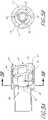
- FIG. 2is a partially sectioned side view of a distal end of the device of FIG. 1 , showing an embodiment of the cutter assembly.
- FIG. 3is a side view of the cutter of FIG. 2 .
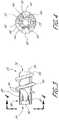
- FIG. 4is an end view of the cutter of FIG. 3 taken along the line 4 - 4 .
- FIG. 5Ais a partially sectioned side view of another embodiment of the cutter and housing.
- FIG. 5Bis a cross-sectional view of the cutter and housing of FIG. 5A taken along the lines 5 B- 5 B.
- FIG. 6is a partially sectioned side view of yet another cutter and housing.
- FIG. 7is a partially sectioned side view of a further cutter and housing.
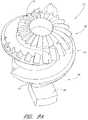
- FIG. 8Ais a top perspective view of a serrated cutter configured in accordance with certain features, aspects and advantages of the present invention.
- FIG. 8Bis a side view of the serrated cutter of FIG. 8A .
- FIG. 8Cis a top view of the serrated cutter of FIG. 8A .
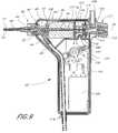
- FIG. 9is a sectioned side view of a control having features, aspects and advantages in accordance with the present invention.
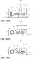
- FIG. 10Ais a schematic illustration of a pinch-valve switch in a position which interrupts an applied vacuum and interrupts power flow to a drive motor.
- FIG. 10Bis a schematic illustration of a pinch-valve switch in a position that applies the vacuum and interrupts power flow to the drive motor.
- FIG. 10Cis a schematic illustration of a pinch-valve switch in a position which applies the vacuum and allows power to flow to the drive motor.
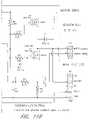
- FIG. 11is a schematic illustration of a representative motor control circuit in accordance with the present invention.
- FIG. 11Ais a schematic illustration of the left portion of a representative motor control circuit in accordance with the present invention.
- FIG. 11Bis a schematic illustration of the right portion of a representative motor control circuit in accordance with the present invention.
- FIG. 12is an enlarged, partially sectioned side view of a cutter, housing and catheter assembly configured in accordance with certain aspects and advantages of the present invention.
- FIG. 13is a schematic view of a treatment process performed according to a first mode of off-set operation.
- FIG. 14is a schematic view of a treatment process performed according to a second mode of off-set operation.
- FIG. 15Ais a schematic view of the middle cerebral artery anatomy and proximal arterial vasculature.
- FIG. 15Bis a detailed view of the middle cerebral artery and adjacent structures.
- FIG. 15Cis a schematic coronal sectional view of the brain and vasculature, including the middle cerebral artery and adjacent structures.
- FIG. 15Dis a schematic close-up view of the Circle of Willis and the anterior and posterior cerebral circulations.
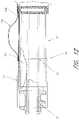
- FIG. 16is a side elevational cross-section of a neurothrombectomy catheter in accordance with one aspect of the present invention.
- FIG. 17Ais a cross-sectional view taken along the line 17 - 17 of FIG. 16 , illustrating a monorail configuration.
- FIG. 17Bis an alternate cross-section taken along the line 17 - 17 in FIG. 16 , illustrating an over the wire configuration.
- FIG. 18is an enlarged detail view of the distal tip of the catheter of FIG. 16 .
- FIG. 19is an enlarged detail view of the proximal opening to the guidewire lumen of the embodiment in FIG. 16 .
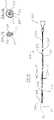
- FIG. 20is a side elevational view of a drive shaft which may be used in the embodiments of FIGS. 16 and 17A .
- FIG. 21is a partially sectioned side view of a cutting element used in the embodiment of FIG. 16 .
- FIG. 22is a distal end view of the cutting element of FIG. 21 .
- a surgical instrumentindicated generally by reference numeral 10 having features, aspects and advantages in accordance with the present invention is depicted therein.
- the illustrative surgical instrumentcomprises an elongate flexible tubular body 12 having a proximal end 14 and a distal end 16 .
- a control 18is preferably provided at or near the proximal end 14 of the tubular body 12 for permitting manipulation of the instrument 10 .
- the control 18advantageously carries electronic controls and indicators as well as vacuum controls as will be discussed below.
- the tubular body 12preferably has an elongate central lumen 20 .
- the tubular body 12has a cutter housing 21 for receiving a cutter 22 that may rotate therein.
- the illustrated cutter 22is coupled to the control 18 for rotation by way of an elongate flexible drive shaft 24 , as will be described below.
- the drive shaft 24is provided with an axially extending central lumen 26 for slidably receiving a guidewire 28 as will be understood by those of skill in the art.
- the cutter 22may also have a central lumen.
- the diameter of the guidewire 28is preferably in the range of about 0.010 inch to about 0.020 inch.
- the lengths of the guidewire 28 and the tubular body 12may be varied to correspond to a distance between a percutaneous access site and a lesion being treated.
- the guidewire 28 and the tubular body 12should be long enough to allow the cutter 22 of the present surgical instrument 10 to track along the guidewire 28 and reach a target occlusion while also allowing a proximal portion of the guidewire 28 to remain exterior to the patient for manipulation by the clinician (not shown).
- guidewireshaving lengths from about 120 cm to about 160 cm may be used, and the length of the tubular body 12 may range between about 50 cm and about 150 cm, as will be understood by those of skill in art.
- the length of the guidewire 28 and the tubular body 12may depend upon the location of the graft or other treatment site relative to the percutaneous or surgical access site.
- Suitable guidewires for coronary artery applicationsinclude those manufactured by Guidant or Cordis.
- the illustrated cutter 22includes a generally cylindrical sleeve shaped body 30 having a central lumen 32 ( FIG. 4 ).
- the cylindrical body 30 of the cutter 22generally has an external diameter of between about 0.035 inch and 0.092 inch. In one embodiment, the external diameter is approximately 0.042 inch.
- the body 30has a wall thickness between about 0.003 inch and about 0.010 inch. In one embodiment, the wall thickness is about 0.009 inch.
- the length of one embodiment of the present cutter 22 from proximal end 34 to distal end 36is approximately 0.096 inch but the length may vary from about 0.040 inch to about 0.120 inch or more, depending upon the intended use. In general, tip lengths of no more than about 0.100 inch are preferred; shorter tip lengths permit greater lateral flexibility and enable increased remote access as will be apparent to those of skill in the art.
- an end cap 38may be formed on the distal end 36 of the present cutter tip 22 .
- the cylindrical body 30may be machined to create an integral (i.e., one piece) end cap 38 .
- the end cap 38may have a thickness of approximately 0.007 inch; however, the end cap thickness may range from about 0.003 inch to about 0.020 inch.
- a discrete end cap 38may also be separately machined and attached.
- the end cap 38may be formed from a more lubricious material to reduce frictional contact between the guidewire 28 and the end cap 38 .
- Such an end capmay be attached in any suitable manner.
- the end cap 38preferably has an outside diameter that substantially corresponds to the outside diameter of the distal end 26 of the present cutter tip 22 .
- the end cap outside diametermay, however, substantially correspond to the inside diameter of the cylindrical body in some embodiments.
- the end cap 38may also have a centrally located aperture 39 .
- the aperture 39if present, preferably has a diameter of between about 0.013 inch and about 0.025 inch. In one embodiment, the aperture 39 has a diameter of approximately 0.022 inch. Desirably, the aperture 39 may accommodate a guidewire 28 or allow fluids to flow therethrough.
- the cutter 22may have a machined or otherwise integrally formed radially inwardly extending annular flange 41 (see FIG. 6 ). It is also anticipated that aspects of the present invention may also be practiced without employing an end cap or inwardly extending annular flange 41 .
- the flange 41may extend fully around the circumference of the cutter 22 or may have portions removed such that the annular flange 41 is actually a series of inwardly projecting tabs. Additionally, an outside distal edge of the end cap 38 or annular flange 41 is desirably broken, chamfered or rounded such that any sharp edge resulting from manufacturing may be removed, and such that the end cap may be rendered substantially atraumatic.
- a connector portion 40is preferably provided at or near the proximal end 34 of the illustrated cutter 22 for securing the cutter 22 within the cutter housing 21 such that the cutter may rotate therein.
- the connector portion 40may be a mechanical, self-locking method to secure the rotating cutter 22 within the cutter housing 21 and to guard against undesired axial movement of the cutter 22 relative to the housing 21 .
- axial movement of the cuttermay be accommodated within the housing 21 , and even within the tubular body 12 , as will be discussed below in more detail.
- the connector portion 40retains the cutter tip 22 within the cutter housing 21 and may reduce the need for such multiple redundancies.
- the connector portion 40may take various forms.
- the connector portion 40generally comprises two outwardly extending radial supports, such as a set of wedge-shaped flanges 42 .
- the flanges 42may be formed by removing material from an annular circumferential flange at the proximal end 34 of the cutter 22 .
- the flanges 42may be formed into the illustrated wedge-shape, although other shapes may also be desirable.
- the flanges 42may also be bent from a proximal extension of the wall of tubular body 30 , or adhered or otherwise secured to the proximal end 34 of the cutter 22 .
- the cutter 22 and flanges 42may be cast or molded using any suitable method dependent upon the material chosen.
- the flanges 42may alternatively be connected to tubular body 30 at a point in between the proximal end 34 and the distal end 36 of the cutter tip.
- FIGS. 2-4Although two opposing flanges 42 are illustrated in FIGS. 2-4 , three or more flanges 42 may be utilized, as will be apparent to those of skill in the art. In general, the flanges 42 should be evenly distributed around the circumference of the cutter 22 to improve balance during rotation of the cutter 22 . For example, three flanges 42 would preferably extend radially outward from the cylindrical wall of the body 30 on approximately 120° centers. Similarly, four outwardly extending radial flanges 42 would preferably be located on approximately 90° centers.
- the outwardly extending radial supports 42are also formed by removing material from an annular circumferential flange at the proximal end of the cutter 22 .
- the supports 42are attached to the balance of the cutter 22 with tangs 43 that are carved from the cutter 22 when the supports 42 are formed. In this manner, the tangs 43 do not require the slots that form the arms described above.
- a combination of the slots and arms and the tangs without slotsmay also be used to attach the flange 42 to the cutter 22 .
- the tangs 43preferably are between about 0.010 inch and about 0.050 inch in length.
- the tangs 43are about 0.015 inch long. In one embodiment, the tangs are about 0.25 inch long. The tangs also have a width between about 0.010 inch and about 0.050 inch. In a presently preferred embodiment, the tangs have a width of about 0.020 inch.
- the illustrated connector portion 40has an outside diameter taken about the opposing flanges 42 of approximately 0.071 inch.
- the outside diametermay range from about 0.057 inch to about 0.096 inch in a device intended for coronary artery applications.
- the thickness of the flanges 42 in the axial directioni.e., the dimension normal to the increase in diameter resulting from the flanges
- an outside diameter defined about the flanges 42may be selected to cooperate with the inside diameter of an annular retaining race or groove 54 in the housing 21 , discussed below, to axially retain the cutter 22 while permitting rotation of the cutter 22 relative to the housing 21 .
- the thickness of the flanges 42 and the axial width of the retaining groove 54also are generally designed to either allow axial movement of the cutter 22 within the housing 21 or to limit or eliminate substantial axial movement of the cutter 22 within the housing 21 , as is discussed below.
- each illustrated flange 42is preferably attached to the cutter 22 by a spring arm 43 .
- Each arm 43is defined by two longitudinally extending slots 44 which are formed in the cylindrical wall of the body 30 adjacent each flange 42 .
- the slots 44are preferably about 0.005 inch in width; however the width may range from approximately 0.001 inch to approximately 0.025 inch.
- the slots 44 of the present cutter 22are also generally at least about 0.025 inch in axial length along the longitudinal axis of the body 30 .
- the slots 44 of the present cutter 22can be varied in axial length to vary the length of the cantilevered arm 43 that connects the flanges 42 to the cutter 22 .
- the slots 44 , and the arm 43 defined between the slots 44 , and the tangsallow radial inward compression of the flanges 42 and spring arms 43 , or tangs, to ease assembly of the cutter 22 within the cutter housing 21 as described below.
- the cutter 22is made of a material having an adequate spring constant as will be understood by those of skill in the art.
- the cutter 22is made from a medical grade stainless steel alloy.
- the chosen materialpreferably has characteristics including the ability to allow the cantilevered spring arm 43 to deflect radially inwardly an adequate distance over the length of the arm 43 without exceeding the elastic limit of the material (i.e., the deflection is an elastic deformation).
- elastic deformationsallow structures to deflect and substantially return to their initial shape or position. For instance, special hardening methods may be used to maintain the elasticity of the selected material in the deflection range necessary for a specific application.
- the cutter 22is snap fit into the cutter housing 21 .
- the arms 43may be deflected radially inward such that the cutter 22 may be inserted into the cutter housing 21 through an aperture or lumen having a smaller ID than the inside diameter of the retaining groove 54 of the cutter housing 21 .
- the cutter 22is inserted from the distal end of the housing 21 and slid proximally through the housing 21 until the flanges 42 snap outward into the race 54 .
- the cutter 22will be retained in this housing even if it separates from its drive element 24 .
- the arms 43substantially return to their original, relaxed positions within the retaining groove 54 the cutter housing 21 following installation. It should be appreciated that the arms 43 may also be maintained under a slight bending stress (i.e., the inside diameter of the race 54 may be smaller than the outside diameter about the relaxed flanges 42 ) if desired.
- the elementmay include a thread 46 that extends along a portion of the exterior surface of the body 30 of the present cutter 22 .
- the thread 46preferably extends distally from a location on the body 30 that is distal to the connector 40 .
- the thread 46may be manufactured using any suitable technique well known to those of skill in the art.
- the major diameter of the thread 46is approximately 0.0681 inch.
- the major diameter of the present thread 46may range from about 0.050 inch to about 0.130 inch or otherwise, depending upon both the inner diameter of the cutter housing and the intended clinical application.
- the thread 46 of the foregoing embodimenthas a pitch of approximately 0.0304 inch and is desirably helical. The pitch may range from about 0.005 inch to about 0.060 inch, and may be constant or variable along the axial length of the cutter 22 .
- the thickness of the present thread 46 in the axial directionis approximately 0.008 inch; however, the thickness may range from about 0.003 to about 0.05, and may be constant or variable along the length of the thread 46 .
- the cutters 22may also have a generally spiral helix thread.
- the thread 46extends approximately two complete revolutions around the cylindrical body 30 .
- the thread 46may be a continuous radially outwardly extending ridge as illustrated, or may comprise a plurality of radially outstanding blades or projections preferably arranged in a helical pattern.
- the thread 46may extend as little as about one-half to one full revolution around the cutter body 30 , or may extend as many as 21 ⁇ 2 or 3 or more full revolutions around the circumference of the body 30 , as is discussed more below.
- optimization of the length of the thread 46may be accomplished through routine experimentation in view of the desired clinical objectives, including the desired maneuverability (i.e., tractability through tortuous anatomy) and the length of the cutter 22 , as well as the nature of the cutting and/or aspiration action to be accomplished or facilitated by the cutter 22 .
- the present cutter 22is illustrated and described as having a single thread, one skilled in the art will appreciate that the cutter 22 may also have multiple threads, a discontinuous thread or no threads.
- the thread 46 illustrated thereinis a constant pitch and varies in cross-section along its length from a relatively low profile at the distal end 36 to a relatively higher profile at the proximal end 34 of the cutter tip 22 .
- Such a ramped thread 46improves performance when the catheter encounters more dense obstructive material.
- the major diameter of the distal lead 47 of the thread 46is smaller than the major diameter of the thread along the more proximal portions of the cutter shaft 30 . It is anticipated that the pitch of the thread 46 may also vary along with the profile of the thread 46 to alter the clinical effects accomplished.
- the pitch of the thread 46may also be varied along the axial length of the cutter body 30 . Varying the pitch allows a modified function at different points along the axial length of the cutter 22 , such as a greater axial thread spacing at the distal end 36 of the cutter 22 to engage material and a relatively closer axial spacing of the threads at the proximal end 34 of the cutter 22 for processing the material.
- the pitchmay range from about 0.010 inch at the distal end to about 0.080 inch at the proximal end.
- the pitch at the distal end 36is approximately 0.034
- the pitch at the proximal end 34is approximately 0.054, and the pitch varies continuously therebetween.
- the maximum and minimum pitch, together with the rate of change of the pitch between the proximal end 34 and the distal end 36can be optimized through routine experimentation by those of skill in the art in view of the disclosure herein.
- the ramped thread diameterresults in a distal portion 36 of the cutter 22 that can extend distally beyond the cutter housing 21 and a proximal portion 34 of the cutter tip 22 that will be retained within the cutter housing 21 .
- the distal portion 45 of the thread 46may have its leading edge broken, chamfered or rounded to remove a sharp corner or edge. By eliminating the sharp corner or edge, the risk of accidental damage to the patient is reduced.
- the distal edge of the cylindrical body 30 and the flanges 42may also be broken, chamfered or otherwise rounded to eliminate or reduce sharp edges.
- the outside diameter of the thread 46 in this embodimenthas a close sliding fit with the inside diameter, or inner wall, of the cutter housing 21 .
- the atheromatous materialwill be avulsed by the threads 46 , fed further into the housing 21 toward the flanges 42 and chopped or minced by the flanges 42 .
- a stationary member(not shown) or a set of stationary members (see, e.g., on FIGS. 21 and 22 ) may be positioned such that the rotating flanges 42 and the stationary member or members (not shown) effect a shearing action.
- the shearing actionbreaks up the strands into shorter sections, which are less likely to clog the instrument, as described below.
- the flanges 42may be provided with sharply chamfered leading or trailing edges to alter their cutting action, if desired.
- annular spacebetween the outside diameter of the thread 46 and the inside diameter of the cutter housing 21 .
- an annular spaceis provided for material to pass through the cutter housing 21 without being severed by the thread 46 of the cutter tip 22 .
- Thismay be utilized in conjunction with vacuum, discussed below, to aspirate material into the atherectomy device without the necessity of complete cutting by the thread 46 or flanges 42 . This may be advantageous if the rate of material removal effected by aspiration is higher than the rate at which material removal may occur with the thread 46 engaging such material.
- the rotational atherectomy device 10may more readily aspirate certain lesion morphologies, such as those including portions of calcified plaque, if the thread 46 is not required to cut all the way through the aspirated material.
- the desired radial distance between the thread 46 and the inside wall of the cutter housing 21will be between about 0.0001 inch and about 0.008 inch, to be optimized in view of the desired performance characteristics of the particular embodiment.
- the cutting function of the thread 46 , or the thread 46 itselfmay be deleted entirely, so that cutting occurs by the flanges or cutting blocks 42 and/or stationary members (not shown) in cooperation with the aspiration provided by a vacuum source.
- Interventions for which an atraumatic distal tip is desiredcan be well served by an atraumatically tipped cutter 22 , as illustrated in FIG. 7 .
- the blunt tip cutter 22preferably has a bulbous or rounded tip 23 that extends from the distal end of the cutter 22 .
- the tip 23preferably has a radially symmetrical configuration such that upon rotation it presents a smooth, atraumatic surface for tissue contact. Viewed in side elevation, such as in FIG.
- the tip 23may have a generally hemispherical, oval, elliptical, aspheric or other smooth curve on its radial surface with either a curved or truncated (i.e., flat) distal surface.
- the shape of the tip 23may be varied to achieve desirable effects on the catheter crossing profile or on soft atheromas, etc.
- the tip 23advantageously minimizes the possibility of traumatic contact between the healthy wall of the vessel and the thread 46 or other cutting element.
- the outside diameter of the tip 23may range from the outside diameter of the cutter body 30 to the outside diameter of the cutter housing 21 . Diameters greater than the housing 21 may also be used, but diameters smaller than the housing 21 facilitate a smaller crossing profile of the instrument 10 .
- the axial length of the tip 23may be varied to suit the intended application, but will generally be within the range of from about 0.050 inch to about 0.100 inch in a coronary artery application.
- the outside surface of tip 23may be provided with surface texturing or treatments.
- the surface texturing or treatmentsmay be formed by abrasive coating (i.e., coating the tip with diamond particles), acid etching or any other suitable method.
- the texture or treatmentsmay be on the distal surface or the lateral surfaces or both such that a two-stage interaction with the encountered materials may occur.
- the tipcan be used for grinding or otherwise remodeling the encountered materials.
- an abrasive distal surfacecan be used to cut through calcified plaque, while a smooth radial surface can compress soft material against the vessel wall to facilitate acceptance into the helical thread 46 of the cutter 22 .
- Varying the distance between the distal end 47 of the thread 46 and the proximal end of the tip 23 , as well as varying its geometry,can allow adjustments to the cutter aggressiveness.
- the thread 46may extend up to the proximal edge of the tip 23 and allow early engagement of the encountered materials relative to a cutter 22 having a length of unthreaded shaft between the proximal edge of the tip 23 and the distal end 47 of the thread 46 .
- the tip 23can be integrally formed with the cutter tip 22 , such as by machining techniques known in the art. Alternatively, it can be separately formed and secured thereto, such as by soldering, adhesives, mechanical interference fit, threaded engagement and the like.
- the tipcan be machined from a suitable metal or molded or otherwise formed from a suitable polymeric material such as polyethylene, nylon, PTFE or others known to those of ordinary skill in the art.
- the cutter tip 22itself may be machined such that the distal facing end is serrated or discontinuously formed.
- the discontinuous threadmay comprise a number of inclined surfaces forming distally facing teeth. In such cutters, the cutter is more aggressive in the forward direction.
- a cutter tip 22may have serrations 57 formed along the distal end 47 of the thread 46 .
- the serrationsmay also be positioned on an extended nose portion (not shown) of the cutter.
- the serrations 57preferably are formed to extend outward radially from the center axis of the cutter 22 . While the illustrated serrations 57 are formed in a straight line, the serrations 57 may also be arcuate in shape to form a sickle-shaped cutting surface.
- the illustrated serrations 57preferably have a depth of between about 0.0005 inch and about 0.0040. More preferably, the serrations 57 are about 0.0020 deep.
- the serrations 57also preferably are formed with a sloping face 59 that is at an angle ⁇ of between about 45° and about 85° with a longitudinal plane that extends through the axis of rotation. In a presently preferred arrangement, the sloping face extends at an angle of about 60° relative to the same plane.
- the run of the sloping face 59is preferably between about 0.0020 inch and about 0.0050 inch. In the preferred arrangement, the run is about 0.0035 inch in length.
- the serrations in the illustrated cutterextend over only a forward facing portion 45 of the distal end 36 of the cutter 22 ; however, it is anticipated that the cutter 22 may also comprise a serrated thread that extends the entire length of the thread 46 .
- FIG. 6illustrates a cutter 22 arranged to float axially within the housing 21 .
- the cutter 22is provided with an anti-locking thread design.
- the thread 46may be configured such that it cannot jam within the housing 21 at either extreme of axial travel.
- Such a configurationmay involve having a minimum thread major diameter which is greater than the diameter of the opening in the distal end of the device 10 or having a pitch which is less than the thickness of the ring flange 41 formed at the distal tip of the cutter housing 21 .
- Other configurationsmay also be readily apparent to those of ordinary skill in the art.
- the axial travel and the thread designdesirably cooperate to allow the cutter 22 to self-adjust to digest soft fibrous material.
- the housing 21may conveniently be assembled from two pieces, to entrap the cutter 22 therein. The two pieces are then laser-welded or otherwise secured together. In one embodiment, the housing 21 may be split longitudinally, the cutter 22 inserted, and the two pieces may then be secured together. In another presently preferred embodiment, the two pieces may split the housing 21 into a distal component and a proximal component (see FIG. 6 ). The two components may be assembled to trap the cutter 22 therein and may then be laser-welded or otherwise secured together.
- Such assembliesallow for the cutter 22 to be captured within the cutter housing 21 as well as allow for certain relatively loose manufacturing tolerances for the cutter 22 and the cutter housing 21 such as will reduce manufacturing costs. Such assemblies also enable better fits because the flanges 42 require less travel (i.e., the flanges 42 do not require deflection for insertion into the housing 21 ).
- the illustrated housing 21internally may be a stepped cylinder having a proximal end 50 and the distal end 52 .
- an annular bearing surface 48(see FIG. 6 ) provides a proximal limit of travel for the flanges 42 on cutter 22 .
- the annular bearing surface 48may be formed within the cutter housing 22 (as illustrated in FIG. 6 ) or within the tubular body 12 (not shown).
- the internal diameter of the distal portion 52 of the cutter housing 21is approximately 0.0689 inch and may range from about 0.050 inch to about 0.150 inch.
- the proximal end 50 of the present cutter housing 21preferably has an internal diameter of approximately 0.0558 inch.
- the internal diameter 50 of the proximal end of the present cutter housing 21may range from about 0.035 inch to about 0.130 inch.
- the cutter housing 21may be provided with a radially inwardly extending retaining lip, such as flange 41 in FIG. 6 , sized and configured such that the cutter 22 is captured within the cutter housing 21 and such that the cutter 22 cannot screw itself out of its captured position within the cutter housing 21 .
- the exterior diameter of the distal end 52 of the cutter housing 21 in one embodimentis approximately 0.0790 inch; however, the distal exterior diameter may range from about 0.039 inch to about 0.150 inch depending upon cutter design and the intended clinical application.
- the distal portion 52 of the cutter housing 21 in the illustrated embodimentis about 0.117 inch in length but the length may vary from about 0.020 inch to about 0.50 inch.
- the outside diameter of the proximal portion 50 of the cutter housing 21may be less than the diameter of the distal portion 52 to produce an annular shoulder 51 to limit concentric proximal advance of the proximal section within the tubular body 12 .
- the proximal section of the housing 50extends axially for approximately 0.09 inch but its length may vary as will be understood by those of skill in the art.
- the cutter housing 21may be integrally formed or separately formed and secured to the distal end 16 of the tubular body 12 in accordance with any of a variety of techniques which will be known to those of skill in the art.
- the concentric overlapping joint illustrated in FIG. 2can be utilized with any of a variety of secondary retention techniques, such as soldering, the use of adhesives, solvent bonding, crimping, swaging or thermal bonding.
- an outer tubular sleeve(not shown) may be heat shrunk over the joint between the cutter housing 21 and the tubular body 12 .
- the proximal portion 50 of the cutter housing 21desirably does not block a portion of the annual recess defined between the central lumen 20 and the outer surface of the drive element 24 . It is anticipated that this style of connection can be utilized with any of the cutter housing features described herein and that the cutter housing 21 may be provided with an internal stop to limit axial displacement of the cutter housing 21 relative to the distal end 16 of the tubular body 12 .
- the retaining race 54in one embodiment is approximately 0.0015 inch deep relative to the inner diameter of the distal section 52 and may range in depth from about 0.0005 inch to about 0.020 inch.
- the retaining race 54 in the illustrated embodimentis about 0.0135 inch in axial width; however, as one skilled in the art will readily appreciate, the race width may be varied and still accomplish its retention function as is discussed further below.
- the race 54may be located proximally, or extend proximally, of the cutter housing 21 such that the cutter 22 may be retracted within the tubular body 12 .
- the retaining race 54cooperates with the flanges 42 of the present cutter 22 to retain the cutter 22 within the cutter housing 21 as described in detail above.
- the flanges 42provide a bearing surface for the cutter 22 to facilitate rotational movement of the cutter 22 relative to the housing 21 .
- the cutter 22may be substantially restrained from axial movement within the cutter housing 21 .
- the race 54may be larger in axial width relative to the thickness of the flanges 42 to allow axial movement of the cutter 22 within the cutter housing 21 or even into the tubular body 12 as discussed above.
- the distal extremity of the illustrated cutter 22may be approximately aligned with the distal extremity of the cutter housing 21 .
- the length of the cutter housing 21 distal of the retaining groove 54substantially corresponds to the length of the portion of the of the cutter 22 which extends distally of the distal surfaces of flanges 42 .
- the distal end 36 of the cutter 22may alternatively extend beyond, or be recessed within, the distal end 52 of the cutter housing 21 (i.e., the embodiment of FIG. 7 ).
- the cutter 22may be arranged for selective extension and retraction relative to the cutter housing 21 , the benefits of which are described below.
- FIGS. 5A and 5BAnother cutter 60 and associated cutter housing 70 are illustrated in FIGS. 5A and 5B .
- the cutter 60embodies many of the same features as the cutter 22 described above, like elements will generally be called out by new reference numerals for ease of discussion. It should be recognized, however, that any of the features, aspects or advantages of the cutter 22 described above and the cutter 60 described below may be easily interchanged by one of ordinary skill in the art.
- the cutter 60is preferably symmetrical about the rotational axis having a body 61 with an annular retention structure, such as a retaining race 62 , located near the body's proximal end 64 .
- the retaining race 62 , or connector portion, in the illustrated embodimentis about 0.007 inch deep, and about 0.008 inch wide, although both dimensions can be varied as may be desired and still achieve the desired retention function, as will be readily recognized by one with skill in the art.
- Proximal to the retaining race 62the outside diameter of the body 61 is rounded or tapers from about 0.04 inch to about 0.036 inch. Preferably, all edges are broken, chamfered or otherwise rounded to ensure burr free and dull corners and to facilitate assembly.
- the cutter 60may also have a thread 66 similar to that described above.
- the cutter 60is preferably snap fit into the cutter housing 70 by inserting the cutter 60 into the distal end 74 of the cutter housing 70 .
- the cutter housing 70is preferably similar to that described above with the exception that the retaining race 54 of the first housing is replaced by a set of inwardly extending radial retaining members 72 .
- the present cutter housing 70has three retaining members 72 , preferably circumferentially symmetrically distributed (i.e., on about 120 ⁇ centers).
- the number, size and shape of the retaining memberscan vary; at least two will generally be used to achieve opposition, and embodiments having 3, 4, 5 or more may be readily utilized. It is possible, however, to utilize a single retaining member in some applications such that the single retaining member operates as a stationary cutter member either with or without a set of cutter blocks ( 42 in the embodiments described above).
- the retaining members 72are sized and configured to allow deflection within the elastic range such that the retaining members 72 may be deflected and inserted into the race 62 as discussed below.
- this snap fit configurationadvantageously enables the cutter 60 to be retained in the cutter housing 70 even if the cutter 60 separates from the driving element (not illustrated).
- the retaining members 72may serve the added function of stationary cutting members. As such the retaining members 72 may be sized accordingly.
- the illustrated retaining members 72are about 0.007 inch thick in the axial direction; however, one skilled in the art will appreciate that the thickness can range from about 0.003 inch to about 0.030 inch or otherwise depending upon material choice and the desired degree of axial restraint.
- the retaining members 72extend about 0.007 inch inward from the interior wall of the cylindrical cutter housing 70 .
- the retaining member 72 lengthcan vary, however, depending upon the desired dimensions of the cutter housing 70 and the cutter 60 .
- the side edges 73 of the retaining members 72may be provided with a radius such that the radial interior and exterior ends are wider than the central portion.
- the stationary retaining members 72may alternatively be provided with a convex radius (not shown) to form a smoothly transitioning profile.
- the retaining members 72are provided to engage within the retaining race 62 of the cutter 60 .
- the retaining members 72 and the race 62may be sized and configured such that the cutter 60 is either substantially restrained from axial movement relative to the cutter housing 70 or some axial travel is allowed between the two components.
- the retaining members 72may also provide a bearing surface for the rotational movement of the cutter 60 relative to the cutter housing 70 .
- the race 62 of the cutter 60desirably rides on the ends of the retaining members 72 such that the retaining members 72 provide bearing surfaces at their inner most edges and allow the cutter 60 to be rotated relative to the housing 70 .
- the distal end 65 of the cutter 60may be approximately flush with the distal end 74 of the cutter housing 70 .
- the distal end 65 of the cutter 60may extend distally from or may be slightly recessed within the distal end 74 of the cutter housing 70 by as much or more than is shown in FIG. 5A .
- the cutter 60may be selectively advanced or retracted relative to the cutter housing 70 , enabling advantages that are described below.
- a flexible drive shaft 24may be firmly secured within an axial bore 32 of the cutter 22 .
- the cutter 22may be secured to the flexible drive shaft 24 by any of a variety of ways such as crimping, swaging, soldering, interference fit structures, and/or threaded engagement as will be apparent to those of skill in the art.
- the flexible drive shaft 24could extend axially through the cutter 22 and be secured at the distal end 36 of the cutter 22 .
- the cutter 22 and the cutter housing 21may be designed so that the cutter 22 may be positioned within the cutter housing 21 in a manner that allows axial movement of the cutter 22 relative to the cutter housing 21 .
- Controllable axial movement of the cutter 22may be accomplished in a variety of ways, to achieve various desired clinical objectives. For example, in either of the embodiments illustrated in FIGS. 2 and 5 a , a minor amount of axial movement can be achieved by increasing the axial dimension of the annular recesses 54 , 62 with respect to the axial dimension of the flanges 42 , or retaining members 72 .
- the annular proximal stop 48( FIG.
- the proximal stop 48can be eliminated entirely such that the entire inside diameter of the tubular body 12 is able to accommodate the flanges 42 or their structural equivalent, or the outside diameter of the thread 46 , depending upon the embodiment. Limited axial movement can also be accomplished in the manner illustrated in FIGS. 6 and 7 , as will be appreciated by those of skill in the art.
- relatively minor degrees of axial movementsuch as on the order of about one or two millimeters or less may be desirable to help reduce the incidence of clogging and also reduce trauma, such as by the distal cutting tip pressing against a vessel wall.
- Minor axial movabilitycan also help compensate for differential elongation or compression between the tubular body 12 and the drive shaft 24 .
- a greater degree of axial movabilitymay be desirable in embodiments in which the cutter 22 may be controllably extended partially beyond the housing 21 such as to improve engagement with hard obstructive material. Retraction of the cutter 22 within the cutter housing 21 may be desirable during insertion of the device 10 , to minimize trauma to the vascular intima during positioning of the device 10 . The cutter 22 may thereafter be advanced distally on the order of 1 to 3 or 5 millimeters beyond the distal end 52 of the housing 21 , such as to engage obstructive material to be drawn into the cutter housing 21 .
- More significant proximal retraction of the cutter 22 within the housing 21may be advantageous during positioning of the atherectomy catheter.
- one of the limitations on positioning of a transluminal medical device within tortuous vascular anatomyis the lateral flexibility of the distal portion of the device. Even if the outside diameter or crossing profile of the device is small enough to reach the stenotic region, the device still must have sufficient pushability and sufficient lateral flexibility to navigate the tortuous anatomy.
- the rotatable drive shaft 24can significantly increase the rigidity of the catheter.
- the drive shaft 24 and the cutter 22may be proximally withdrawn within the tubular housing 12 to provide a relatively highly flexible distal catheter section that is capable of tracking a guidewire 28 through tortuous vascular anatomy.
- the cutter 22 and the drive shaft 24may be distally advanced through the tubular body 12 and into position at the distal end 16 . In this manner, the rotational atherectomy catheter can be positioned at anatomical locations that are not reachable if the drive shaft 28 and housing 21 at the distal end 16 of the tubular body 12 are advanced as a single unit.
- the cutter 22is preferably proximally retractable from the distal end 52 of the cutter housing 21 by a distance sufficient to permit the outer tubular body 12 and cutter housing 21 to be positioned at the desired treatment site.
- the distance between the distal end 52 of the cutter housing 21 and the retracted cutter 22is generally be within the range of from about 5 cm to about 30 cm and preferably at least about 10 cm. Proximal retraction of the cutter 22 over distances on that order will normally be sufficient for most coronary artery applications.
- the flexible drive shaft 24is preferably a hollow, laminated flexible “torque tube” such as may be fabricated from an inner thin-wall polymeric tubing, an intermediate layer of braided or woven wire, and an outer polymeric layer.
- the torque tubecomprises a polyimide tube having a wall thickness of about 0.004 inch, with a layer of braided 0.0015 inch stainless steel wire embedded therein.
- the laminated constructionadvantageously produces a tube with a very high torsional stiffness and sufficient tensile strength, but which is generally laterally flexible. However, depending upon the desired torque transmission, diameter and flexibility, any of a variety of other materials and constructions may also be used.
- the drive shaft 24should have sufficient torsional rigidity to drive the cutter 22 through reasonably foreseeable blockages. It is also recognized that in some applications, the drive shaft 24 may be a wire or other solid construction such that no inner lumen 26 extends therethrough.
- the outside diameter of one embodiment of the present hollow flexible drive shaft 24is approximately 0.032 inch, but may range between about 0.020 inch and about 0.034 inch or more.
- the diameter of the flexible drive shaft 24may be limited by a minimum torsional strength and a guidewire diameter, if a guidewire 28 is present, at the low end, and maximum permissible catheter outside diameter at the high end.
- a hollow drive shaft 24allows the device 10 to be advanced over a conventional spring-tipped guidewire 28 , and preferably still leaves room for saline solution, drugs or contrast media to flow through the lumen 26 of the drive shaft 24 and out of the distal opening 39 on the cutter 22 .
- the internal diameter of the present hollow flexible drive shaft 24is thus partially dependent upon the diameter of the guidewire 28 over which the flexible drive shaft 24 must track.
- the internal diameter of the guidewire lumen 26 in one embodiment of the present hollow flexible drive shaft 24intended for use with a 0.018 inch diameter guidewire, is approximately 0.024 inch. Because the flexible drive shaft 24 preferably extends between the control 18 and the cutter 22 , the length of the present hollow flexible drive shaft 24 should be sufficient to allow the cutter assembly to reach the target location while also allowing adequate length outside of the patient for the clinician to manipulate the instrument 10 .
- the lumen 20 of the assembled device 10is thus an annular space defined between the inside wall of the flexible tubular body 12 and the outside of the flexible drive shaft 24 .
- This lumen 20may be used to aspirate fluid and material from the cutter.
- sufficient clearanceis maintained between the tubular body 12 and the rotating drive shaft 24 to minimize the likelihood of binding or clogging by material aspirated from the treatment site.
- the cross-sectional area of the lumen 20is preferably maximized as a percentage of the outside diameter of the tubular body 12 . This permits an optimization of lumen cross-sectional area which maintains a minimal outside diameter for tubular body 12 , while at the same time permitting an acceptable flow rate of material through the aspiration lumen 20 , with minimal likelihood of clogging or binding which would interrupt the procedure.
- Cross-sectional area of the aspiration lumen 20thus may be optimized if the drive tube 24 is constructed to have relatively high torque transmission per unit wall thickness such as in the constructions described above.
- the outside diameter of tubular body 12is about 0.080 inch, the wall thickness of tubular body 12 is about 0.008 inch, and the outside diameter of the drive shaft 24 is about 0.031 inch.
- Such a constructionproduces a cross-sectional area of the available aspiration portion of central lumen 20 of about 0.00245 square inch. This is approximately 50% of the total cross-sectional area of the tubular body 12 .
- the cross-sectional area of the lumen 20is at least about 25%, more preferably at least about 40%, and optimally at least about 60% of the total cross-sectional area of the tubular body 12 .
- the tubular body 12may comprise any of a variety of constructions, such as a multi-layer torque tube. Alternatively, any of a variety of conventional catheter shaft materials such as stainless steel, or single layer polymeric extrusions of polyethylenes, polyethylene terephthalate, nylon and others well known in the art can be used.
- the tubular body 12is a PEBAX extrusion having an outside diameter of approximately 0.090 inch.
- the outer diametercan vary between about 0.056 inch for coronary vascular applications and about 0.150 inch for peripheral vascular applications.
- the foregoing tubular body 12desirably has a wall thickness of at least about 0.005 inch. The wall thickness can, however, be varied depending upon materials and design.
- the distal end of the tubular body 12may be affixed to the proximal end 50 of the cutter housing 21 as shown in FIG. 2 and described above.
- the proximal end of the tubular body 12may be affixed to the control 18 as described below.
- a reinforcing tube 80is desirably provided to reduce the likelihood of a failure at that location due to bending forces.
- the reinforcing tube 80may extend from the control unit 18 along a proximal portion of the tubular body 12 .
- the reinforcing tube 80preferably extends distally over the tubular body 12 at least about 3 cm and more preferably about 6 cm, and desirably comprises silicone or other conventional biocompatible polymeric material.
- the illustrated reinforcing tube 80provides support to avoid over bending and kinking at the proximal end of the drive shaft 24 .
- the reinforcing tube 80may be fastened to the control 18 such as by interference fit over a snap tip assembly 82 through which the flexible drive shaft 24 and tubular body 12 enter the control 18 .
- the reinforcing tube 80advantageously envelops a proximal portion of the tubular body 12 .
- the flexible drive shaft 24 and the tubular body 12operatively connect the cutter 22 and the cutter housing 21 to the control 18 of the illustrated embodiment.
- the tubular body 12 and the drive shaft 24enter the control 18 through the snap tip assembly 82 .
- the snap tip assembly 82may be provided with a connector, such as a hub 84 , having a central lumen in communication with a vacuum manifold 86 .
- the tubular body 12may be connected to the hub 84 .
- the hub 84may snap onto and seal a vacuum manifold 86 to the hub 84 and, consequently, to the tubular body 12 .
- the hub materialtherefore, desirably provides long-term memory for snap-fit tabs that secure this part to the rest of the assembly.
- the presently preferred hub 84is injection molded using a white acetyl such as Delrin.
- the hub 84may be rotatable, and may enable the operator to rotate the tubular body 12 relative to the control 18 such that the operator, or clinician, may steer the tubular body 12 without having to move the control 18 along with the tubular body 12 . Friction to limit this rotation may be provided by a bushing 87 that is compressed against the hub 84 in the illustrated embodiment.
- the tubular body 12may be reinforced internally where it passes through the hub 84 , such as by a thin-wall stainless steel tube (not shown) that extends through and is bonded to the hub 84 .
- a good rotational couplingis desired between the tubular body 12 and the hub.
- a portion of the hub boremay be hexagonal shaped, or formed in any other non-circular shape which corresponds to a complementary shape on the tube to enhance the rotational connection between the hub bore and the tube (not shown).
- Epoxy or other adhesivesmay also be injected into a space around the stainless steel tube to help prevent the stainless steel tube (not shown) from rotating relative to the hub 84 .
- the adhesivealso advantageously secures the two components such that the tube (not shown) is less likely to axially pull out of the hub 84 .
- the vacuum manifold 86is preferably fastened to a vacuum hose 88 at one outlet and to a motor 90 at a second outlet.
- the hub-end of the vacuum manifold 86desirably houses two silicone rubber O-rings 85 that function as dynamic (rotatable) seals between the manifold 86 and the steel tube (not shown) which extends through the hub 84 .
- the opposite end of the manifold 86near the proximal end of the drive tube 24 , preferably contains a pair of butyl rubber fluid seals 94 . These dynamic fluid seals 94 may be lubricated with silicone grease.
- the two fluid seals 94are mounted back-to-back, with their lips pointing away from each other.
- the distal seali.e., closest to the cutter 22
- the proximal seali.e., closest to the motor 90
- the vacuum manifold 86may be connected to the motor 90 through use of a threaded motor face plate 100 .
- the vacuum manifold 86is preferably threaded onto the face plate 100 but may be connected in any suitable manner.
- the face plate 100may be attached to the output end of the motor 90 by a threaded fastener 102 .
- the presently preferred motor 90is a modified 6-volt direct-current hollow-shaft, 22 mm outside diameter motor built by MicroMo.
- poweris transmitted from the motor 90 to the flexible drive shaft 24 by a length of medium-wall stainless steel tubing that is preferably adhesively-bonded to the drive shaft 24 .
- the tubingforms a transfer shaft 107 and is preferably coated on the outer surface with approximately 0.001 inch of Type-S Teflon.
- the Teflon-coated, exposed ends of the rigid drive shaft, or transfer shaft 107provide a smooth wear-surface for the dynamic fluid seals discussed above.
- the transfer shaft tubingmay be hypodermic needle stock measuring approximately 0.036 inch inside diameter by 0.053 inch outside diameter, before coating.
- the transfer shaft 107desirably is slip fit through the approximately 0.058 inch inside diameter of the hollow motor shaft, and desirably extends beyond the length of the motor shaft in both directions.
- the slip fitadvantageously accommodates axial sliding movement of the transfer shaft 107 relative to the motor 90 and the balance of the instrument 10 .
- axial movabilitymay be accommodated.
- the drive shaft 24is advantageously capable of axial movement relative to the motor 90 as described above. Controlled axial movement of the drive shaft 24 , and ultimately the cutter 22 and its connected components, is desirable regardless of the mechanical connection allowing such movement.
- the movementallows the cutter 22 and, in some embodiments, the drive shaft 24 to be withdrawn proximally during placement of the catheter sheath, or tubular body 12 , in the vasculature. Following positioning, the cutter 22 may then be advanced forward into a cutting position.
- Such a configurationallows increased maneuverability and flexibility during positioning and easier tracking through the vasculature. This configuration also allows for easier sterilization of the outer tubular body 12 in a compact coiled package.
- such relative axial movement of the cutter 22 and the tubular body 12is not necessary for utilization of various other aspects and advantages of the current invention.
- a small drive plate 103bonded to the rear end of the transfer shaft 107 , advantageously couples with a drive sleeve 105 that is attached to the approximately 0.078 inch outside diameter motor shaft 92 .
- the drive plate 103may be any of a number of geometric configurations.
- the drive plate 103is a rotationally symmetrical shape having a central aperture although other configurations may also be used. The symmetry facilitates rotational balancing.
- the drive plate 103is square with a central aperture, triangular with a central aperture, or circular with a central aperture, with a connecting member to tie the drive plate to the drive sleeve with a reduced likelihood of slippage.
- the drive plate 103 and the drive sleeve 105form a concentric drive coupling, similar to a spline connection, between the motor shaft 92 and the transfer shaft 107 .
- the transfer shaft 107may be connected to the flexible drive shaft 24 .
- the concentric drive coupler configurationpreferably allows approximately 0.25 inch of relative longitudinal movement between the drive plate 103 and the drive sleeve 105 , which is sufficient to accommodate thermal and mechanical changes in the relative lengths of the outer tube 12 and flexible drive tube 24 .
- An integral flange on the drive plate 103 or the drive sleeve 105may serve as a shield to deflect fluid away from the rear motor bearings in the event of a leaking fluid seal.
- the drive sleeve 105is preferably a solid walled annular flange which acts as a tubular deflection as will be understood by those of skill in the art.
- the drive sleeve 105 and the drive plate 103are preferably molded from Plexiglas-DR, a medical-grade, toughened acrylic resin made by Rohm and Haas. These parts have shown little tendency to crack in the presence of the chemicals that might be present or used in the assembly of the device; these chemicals include cyanoacrylate adhesives and accelerators, motor bearing lubricants, alcohol, epoxies, etc.
- the drive sleeve 105 and the drive plate 103are also preferably lightly press-fitted to their respective shafts 92 , 107 , and secured with a fillet of adhesive applied to the outside of the joints.
- an infusion manifold 108may be arranged at the proximal end of the control 18 .
- the infusion manifold 108is preferably designed as an input circuit; thus any fluid that can be pumped or injected at a pressure exceeding the diastolic pressure in the artery or vein could be used, but saline solutions, therapeutic drugs and fluoroscope contrast media are most likely to be used with this device.
- saline solutionsmay be used to purge air from the tubular body 12 and drive tube 24 before performing procedures such that air embolism may be avoided, and may also be used during an atherectomy procedure to provide a continuous flow of liquid (other than blood) during cutting to help carry debris through a return circuit.
- the device 10generally is purged of air prior to performing procedures.
- an infusion pump or elevated IV bagmay be used to ensure a continuous, low-pressure flow of saline solution through the system, depending upon the application and procedure.
- Contrast mediumis a relatively dense material and high pressure (usually several atmospheres) is usually required to force the material quickly through the small, elongated lumen 26 of the drive tube 24 .
- Such a mediummay be infused using an infusion pump, for instance.
- the infusion manifold 108may be comprised of several components.
- the first componentmay be an infusion port that may contain a medical infusion valve 109 , such as that supplied by Halkey-Roberts Corp.
- This silicone rubber check valve assembly 109is preferably designed to be opened by insertion of a male Luer-taper (or lock) fitting.
- the valve 109more preferably stays open as long as the taper fitting remains in place, but desirably closes immediately if it is withdrawn. This action provides simple access when needed, but provides the required backflow protection to minimize loss of blood through this route.
- the infusion valve 109is preferably permanently bonded into a side arm of a flush port manifold 111 , an injection-molded, transparent acrylic fitting.
- the flush port manifold 111desirably has an integral threaded extension that may protrude from the proximal side of the control 18 .
- the threaded extensionmay be provided with a silicone guidewire seal 113 , and an acetyl (Delrin) guidewire clamp nut 112 that together function as a hemostasis valve compression-fitting. Delrin may be used for the clamp nut 112 to minimize stiction and galling of the threads during use. Note that the materials indicated for the compression-fitting may be varied as will be recognized by those of skill in the art.
- An internal shoulder on the threaded portion of the nut 112advantageously acts as a position stop, preventing extrusion of the seal 113 that might otherwise result from over-tightening.
- the guidewire 28desirably extends through both the seal 113 and the nut 112 .
- the guidewire seal 113may compress against the guidewire 28 to lock it in place and to prevent leakage of blood or air through the seal 113 .
- the clamp nut 112is first loosened to reduce the clamping action somewhat and the relative movement is then initiated. If no guidewire 28 is used, the seal 113 may compress against itself and close off the passageways to reduce or prevent leakage.
- a fluid channeladvantageously extends through the flush port manifold 111 , continuing through the open lumen of the drive tube 24 , through a distal aperture 39 in the distal extremity of the cutter 22 .
- the guidewire 28preferably follows the same path. A leak-proof connection between the flush port manifold 111 and the drive tube 24 is therefore desirable.
- a flush port flange 106may be bonded to the motor end of the flush port manifold 111 , creating a chamber housing a low durometer butyl rubber lip seal 114 .
- the flange 106may be manufactured of molded acrylic or the like.
- the lip seal 114forms an effective dynamic seal against one end of the transfer shaft 107 .
- Lip sealsare pressure-compensating devices that function at zero or low pressure by light elastomeric compression against a shaft, minimizing the drag component in a dynamic application. When pressure against the seal increases, the lip tightens against the shaft, increasing both the sealing action and the dynamic friction. In this application, however, a high pressure sealing requirement preferably is only encountered during injection of contrast medium, typically when the cutter 22 is not rotating. Lower pressure dynamic sealing may be required during saline infusion, however, so pressure compensating lip seals are presently preferred.
- the lip seal 114is desirably transfer-molded butyl rubber, with about a 0.047 inch inside diameter lip (generally within the range of from about 0.035 inch to about 0.050 inch), running on the transfer shaft 107 , which may have an outside diameter of approximately 0.055 inch.
- Medical-grade silicone greasemay be used lubricate the interface between the lip seal 114 and the transfer shaft 107 , but the grease tends to be forced away from the lip during prolonged use.
- a Teflon coating on the transfer shaft 107may act as a back-up lubricant to reduce or eliminate seal damage in the event the grease is lost.
- the vacuum hose 88may be attached to the remaining port of the Y-shaped vacuum manifold 86 .
- the hose 88may be attached in any suitable manner as will be appreciated by those of ordinary skill in the art.
- the vacuum hose 88generally extends between the vacuum manifold 86 of the control 18 and a vacuum source (see FIG. 1 ) such as a house vacuum of the catheter lab of a hospital or a vacuum bottle.
- the vacuum hose 88desirably extends through a switch configuration 120 described in detail below. In the illustrated embodiment, the vacuum hose 88 then further extends to the bottom portion of the control 18 .
- a pinch resistant sleeve 116may be provided to prevent the pinching of the vacuum hose 88 as it exits the control 18 . Additionally, the pinch resistant sleeve 116 provides a liquid seal to further reduce the likelihood of liquids entering the control 18 unit during operation.
- an aspect of the present inventioninvolves a cutter lock-out mechanism that will not allow cutting of material unless sufficient aspiration is present.
- the aspiration ratemay be directly sensed (i.e., flow monitoring) or indirectly sensed (i.e., vacuum monitoring).
- the vacuum levelmay be monitored to determine when a new vacuum bottle should be employed. In such a situation, if the level of a sensed vacuum drops below about 15 inches Hg, insufficient clearing vacuum is present and the risk of blockage within the device 10 increases.
- a cutter lock-out mechanismshould be employed to prevent cutting of material until the vacuum level is replenished. Specifically, it has been determined that a sensed vacuum of about 13.5 to about 14 inches Hg usually precedes clogging in the illustrated embodiment.
- the cutter lock-out mechanismis generally comprised of two components, either of which may find utility individually or in combination.
- One of the componentsis a vacuum monitor.
- the vacuum monitor(not shown) is desirably a linear pressure transducer that senses the presence of an adequate vacuum force.
- the signal from the transduceris preferably utilized to enable an automatic override of the motor such that the motor cannot turn the cutter 22 if the vacuum drops below a threshold level (e.g. 15 inches Hg).
- a threshold levele.g. 15 inches Hg
- the vacuum monitormay also comprise a vacuum detector, a comparator of any suitable type, an alarm or circuit cut-out.
- the vacuum detectormay sample the state of operation of the vacuum, the comparator may determine varying operating conditions, and if the vacuum force drops below or unexpectedly and suddenly exceeds the pre-set threshold level for any reason the alarm can alert the operator to take corrective action, and/or the cut-out circuit can automatically stop rotation of the cutter.
- the cutter lock-out mechanismmay also comprise a flow monitor (not shown).
- the flow monitormay be of any suitable type and may simply monitor the flow rate, or aspiration rate, through the aspiration channel.
- the flow monitoralso may be connected to circuitry or alarms such that the user may be warned if the aspiration rate slows (i.e., conditions indicative of a blockage arise) and/or such that the device 10 may automatically take corrective action when a decrease in the aspiration rate is detected. For instance, the device 10 may disable cutting (i.e., rotation of the cutter 22 ), increase the suction level or otherwise attempt to auto-correct the situation.
- various alarmsbe they visual, tactile or auditory, may be utilized to inform the operator or clinician of the alert status.
- a switch arrangementthat advantageously controls the motor state and vacuum application as described below.
- a switchmay be mechanical, electromechanical, or software-controlled.
- a schematically illustrated switch configuration 120desirably assures that the motor 90 driving the rotatable drive shaft 24 , which in turn drives the cutter 22 , may not be activated unless the vacuum is being applied.
- the illustrated pinch valve switch 120generally comprises a push button oriented along the Z axis shown in FIG. 10A .
- the switch push button 124may translate along the Z axis when depressed by the user.
- the lower portion of the push button 124is provided with a u-shaped cut out forming a tunnel along the x-axis.
- the cut outis preferably sized to correspond to a compression spring 126 extending therethrough.
- the presently preferred compression spring 126is a precision-length stack-wound button spring fabricated from 0.027′′ diameter 302 stainless steel wire, with a closed retainer loop at one end.
- the push button 124may be positioned along a portion of the compression spring 126 such that the push button 124 rests on the compression spring 126 and is supported in an up position.
- the switch push button 124thus can travel to a down position when depressed by the operator to a position such as that shown in FIG. 10B .
- the compression spring 126provides a bias such that the push button 124 will return to the up position when released.
- any other suitable biasing mechanism or componentmay also be used.
- the switch push button 124may be further provided with an axial arm 128 that preferably extends in a direction perpendicular to the direction of travel of the push button 124 .
- the armmay assume an “L” shaped configuration. It is anticipated that a variety of arm configurations may also be employed.
- An electronic switch 130is desirably located below the axial arm 128 of the switch push button 124 .
- the electrical switch 130when closed, allows current to flow from a power source 122 to the motor 90 .
- depression of the push button 124creates a flow of current that drives the motor 90 .
- the motor 90drives the drive tube 24 and cutter 22 of the present surgical instrument 10 as described above.
- the compression spring 126is also preferably attached to a pinching member 132 of the switch configuration 120 .
- the compression spring 126is advantageously initially deflected.
- the deflection in the compression spring 126causes the pinch member 132 to retract.
- the pinch member 132is retracted once the push button 124 is depressed.
- a vacuumis initiated and aspiration flow is allowed to pass the pinch valve 120 .
- the amount of flow past valvemay depend on how far the button 124 is depressed, enabling control of the amount of suction (and, thereby, the level of aspiration) if desired. Further depression of the push button 124 beyond the retraction point initiates a contact of the electrical switch 130 and, therefore, allows the motor 90 to be powered only after the vacuum flow has begun.
- FIG. 10Aillustrates a relaxed, non-depressed condition in which the vacuum hose 88 is closed by the pinch valve 132 and the spring 126 , and the electrical switch 130 which controls power supply to the motor 90 is open.
- the push button 124is partially depressed, thereby causing the vacuum hose 88 to be opened while maintaining the electrical switch 130 open.
- Further depression of the push button 124illustrated in FIG. 10C , closes the electrical switch 130 while the vacuum hose 88 is maintained in an open state.
- depressing the push button 124an initial amount starts the vacuum first and further depression initiates the cutting action.
- Such timingreduces risks associated with cutting without aspiration. Because repeated cycles of opening and closing the valve may tend to shift the position of the tube 88 , internal ribs (not shown) are preferably provided in the control 18 to maintain the proper position of the tube 88 .
- a return flow path of the illustrated device 10 for aspiration and the likestarts at the cutter 22 , passes through the helical thread 46 and the cutter blocks 42 of the cutter 22 (and stationary blocks of the cutter housing, if present), continues through the outer lumen 20 of the outer tube 12 to the vacuum manifold 86 , and then passes through a length of vacuum tubing 88 to a tissue collection/fluid separation container, such as a vacuum bottle.
- the return flowmay be assisted by a positive vacuum supply, such as the vacuum bottle or a house vacuum, as is known in the art.
- the collection containermay be connected to a vacuum collection canister that may be, in turn, hooked to a regulated central vacuum source or a suction collection pump or evacuated container.
- the pinch valve assemblyis preferably designed with a “shipping lock-out” feature (not shown) that secures the button 124 in a partially depressed position where the vacuum tube 88 is no longer compressed, but the switch 130 is not yet actuated. This preserves the elastic memory of the pinch tube and protects the device from accidental actuation during handling or storage.
- a thin, flexible lock-out wire with an identifying tagcan be inserted at the last stage of instrument manufacturing, passing through a hole in the button (not shown) and extending through a notch in the side wall of the control 18 .
- a highly-visible tagprotrudes from the side of the control 18 , preventing use of the device until the wire is pulled free. Removing the lock-out wire releases the button 124 and returns the control 18 to a functional condition.
- the lock-out wiredesirably cannot be reinserted without disassembly of the control 18 .
- the device 10is preferably controlled by electronic circuitry such as may be contained on a printed circuit board 133 .
- the circuitry providing the power to the motor 90may also include a circuit to check the load on the motor.
- An exemplary motor control and feedback circuitis illustrated in FIG. 11 ; FIG. 11A illustrates the left portion of this representative motor control circuit, and FIG. 11B illustrates the right portion.
- many other motor control circuitsmay also be implemented. As is known, when a direct current motor, as used in this invention, encounters resistance to rotational movement, an increased load is placed on the power source 122 .
- the circuitryis provided with the capability to identify, indicate, record and possibly compare the speed and/or torque to previously recorded speeds or torques. Specifically, the speed and/or torque, as indicated by the level of current to the motor, may be compared over time through the use of a comparator. Additionally, a reverse switch may be provided to reverse out of jams or potential jams when necessary. Such a reverse switch may be a momentary switch or any other suitable switch as will be recognized by those of skill in the art.
- a motor controller 134preferably provides the motor 90 with sufficient energy by using a combination of missing pulse and pulse width modulation.
- the motor speedmay be sensed by measuring the back electromotive force (EMF), which is proportional to speed. A portion of the back EMF may be fed to the controller 134 , which preferably varies the drive power to the motor 90 to maintain a constant speed.
- EMFback electromotive force
- the circuit values of the controller 134allow motor speed settings of about 1,000 RPM to about 8,000 RPM.
- the speed chosen for no load operationin one embodiment may preferably range from approximately 1,500 RPM to about 5,000 RPM. In a presently preferred embodiment, the no load operation speed is approximately 2,000 RPM.
- the motor speeds associated with the present inventionare less than those associated with abrasive-type devices and turbulence-based devices as will be recognized by those of skill in the art.
- the motor control circuitrymay limit the motor torque to a range of about 0.10 oz-inches to about 0.45 oz-inches by sensing the motor current and setting the motor drive power to the appropriate level.
- a switching controllerthus, may be used for two reasons: (a) it is very efficient—it uses less than 0.015 amperes (the motor current would vary from 0.05 to 0.4 amperes, or perhaps more), and (b) it can deliver appropriate torque instantly or on demand, even at low motor speeds, so the likelihood of stalling is minimized.
- the power source 122may not be electrically connected to the controller 134 until the push button 124 is depressed, as discussed above, so standby power drain is advantageously eliminated or reduced.
- a light emitting diodeLED is desirably on when the motor is running at normal loads (i.e., the sensed current level is lower than a predetermined current level requiring an alert). This LED may be green in some embodiments and will be referred to as such in connection with the illustrated embodiment. Another LED turns on at a motor current of approximately 0.25 amperes, or another threshold level that may indicate a motor “overload” situation. This LED may be red in some embodiments and will be referred to as such in connection with the illustrated embodiment.
- the red LEDmay indicate that the current is proximate, or has achieved, a predetermined maximum safe value.
- the preset maximum safe valueis the upper limit, as determined by the specific design and configuration of the device 10 , for current that indicates an overload condition.
- another feature of the present inventionincludes the ability to provide feedback to the operator based upon motor load. This is advantageous in that the operator can be alerted to a potential binding of the instrument and react accordingly. For instance, the progression rate of the instrument may be reduced or stopped or the instrument may be backed from the trouble location using the reverse switch or otherwise. It should also be understood that the device may make automatic adjustments to the motor speed relative to the sensed load utilizing methods which would be readily apparent to one skilled in the art following a review of FIG. 11 .
- any of a variety of tactile, auditory or visual alarmsmay also be provided either in combination with, or as alternatives to, each other and the LEDs.
- the surgical instrumentcould vibrate or provide an audible signal when it encounters an overload situation.
- the pulses or tonesmay vary to correspond to any variance in resistance to rotation.
- the pitchmay increase with resistance or the speed of a repeating pulse of sound may increase.
- a visual signalcould be sent to the monitor to display the operating characteristics of the surgical equipment.
- other variations of alerting the operator to the operating characteristics of the present inventionmay be provided.
- the present inventionthus provides feedback to the clinician in real time during the progress of the rotational atherectomy procedure.
- Real time feedbackcan allow the clinician to adjust the procedure in response to circumstances that may vary from procedure to procedure, thereby enhancing the overall efficiency of the procedure and possibly minimizing additional risks such as the creation of emboli.
- Pressing the cutter 22 into a lesion with too much forcemay produce an increased load, which can then be detected by the circuitry 131 and communicated to the clinician in any of a variety of ways as has been discussed. This may allow the clinician to ease back on the distal advancement force and/or adjust the vacuum or RPM of the cutter 22 , such as by reducing the advancement force and lowering the resistance to rotation of the cutter 22 , until the load is reduced to an acceptable level, and continue with the procedure.
- the loadis likely to have increased; therefore, the clinician is alerted to such an increase in load such that corrective action may be taken.
- the aspiration ratemay also return to an acceptable level in some embodiments.
- the loadmay increase due to a blockage and the blockage would lower the aspiration rate; however, clearing the blockage will generally return the aspiration rate to a desired level as well as reduce the load on the motor.
- Another aspect of the present inventioninvolves a selectively reversible tip rotation.
- the drive motormay be reversed such as by manipulation of the reverse control switch (not shown) on the handle of the control 18 .
- Motor reversing circuitrywith or without a variable speed control, is well understood by those of skill in the art.
- Momentary reversing of the direction of rotation of the distal cuttermost likely at a relatively low speed of rotation, may be desirable to dislodge material which may have become jammed in the cutter tip. In this manner, the clinician may be able to clear a cutter tip blockage without needing to remove the catheter from the patient and incur the additional time and effort of clearing the tip and replacing the device.
- Low speed reverse rotation of the cuttermay be accomplished in combination with a relatively increased vacuum, to reduce the likelihood of dislodging emboli into the blood stream. Following a brief period of reverse rotation, forward rotation of the cutter tip can be resumed. Whether the obstruction has been successfully dislodged from the cutter tip will be apparent to the clinician through the feedback mechanisms discussed above. Moreover, it is anticipated that the device may alternatively have substantially the same torque, speed, vacuum force, and alarm thresholds when the cutter is rotated in either direction. It is, however, presently preferred to utilize the same speed of rotation in both forward and reverse rotation.
- the motor controllerhas an LM3578A switching regulator, indicated generally by U 1 in FIG. 11 .
- the switching regulatormay be an LM3578A switching regulator in some embodiments; one of ordinary skill in the art will readily recognize other components and circuitry that can perform essentially the same functions.
- the switching regulatoris normally used as a power supply regulator, wherein it may provide a substantially constant voltage regardless of load.
- a negative in jack (pin 1 )may be used as an error input. For instance, when the voltage at pin 1 is less than about 1 volt, an inference may be established that the motor speed may be too low, therefore the output jack (pin 6 ) goes low.
- the comparisonadvantageously continues during the 90% period, with the output on or off as determined by the error signal. If the motor speed were to increase to the proper level during the 90% portion of the cycle, the output would preferably shut off immediately, thereby resulting in a narrowed pulse. Hence, pulse width modulation is achieved.
- the output of the switching regulator U 1only goes low, so R 1 preferably pulls the output high when the switching regulator U 1 is off.
- R 13isolates the switching regulator U 1 from the gate capacitance of Q 1 , thereby advantageously ensuring a more reliable start-up of the switching regulator U 1 upon application of power.
- D 1preferably prevents below-ground motor switching transients from reaching the transistor Q 1 .
- the VP2204may have a 40-volt rating, which advantageously provides plenty of margin for withstanding voltage transients.
- any other suitable control circuitmay also be utilized.
- Power supply filter C 5preferably helps provide the large short duration currents demanded by the controller, especially when the battery power is nearly depleted.
- an N-channel FETpreferably switches the motor's back EMF to a storage capacitor C 2 during the portion of the control cycle when the motor is not powered (i.e., Q 2 is off when Q 1 is on, and vice versa).
- the resistor R 2along with the gate capacitance of the FET Q 2 , advantageously forms a delay network so that when the FET Q 2 turns on after the FET Q 1 turns off. This configuration may block turn-off transients and may present a voltage to C 2 that more accurately reflects the back EMF.
- a resistor R 5 and a resistor R 6preferably divide the back EMF to provide the error voltage (nominally about 1 volt) to pin 1 of the switching regulator U 1 .
- the value of the resistor R 5desirably determines the level of back EMF, and, therefore, the motor speed required to produce about 1 volt at the switching regulator U 1 , pin 1 .
- the resistor R 4may be in series with the motor and may be used to sense the motor current and limit the motor torque accordingly. For instance, the current pulses through the resistor R 4 generate voltage pulses, which may be integrated (averaged) by the resistor R 3 and the capacitor C 1 and fed to pin 7 of the switching regulator U 1 , which is the current limit input.
- the switching regulator U 1may not increase the output drive, regardless of the error voltage.
- the circuit values shownresult in about 0.45 amp average, or between about 0.45 and about 0.5 oz-in. of stall torque for the motor.
- the back EMF voltage stored by the capacitor C 2is preferably further filtered by a resistor R 7 and a capacitor C 3 and may appear at the output (pin 7 ) of an amplifier (U 2 ) as a relatively noise-free signal which follows the motor speed with a slight time lag.
- the amplifier in the illustrated embodimentis an LM358 buffer amplifier.
- the voltageis desirably divided by a resistor R 8 , a resistor R 9 and a resistor R 10 and may appear at the positive input of the comparator section of the amplifier U 2 (pin 3 ).
- a negative inputis desirably fixed at about 1 volt, since it is connected to the switching regulator U 1 , pin 2 .
- a test connector P 2provides signals and voltages for production testing of the controller board, which may be tested as a subassembly prior to installation.
- the test connector P 2may also be accessible when the top half of the housing is removed, such as for testing at higher levels of assembly. It should be appreciated that one of skill in the art may modify the test connector and related circuitry such that the connector could also become a data bus all data to be passed from the control to a recorder, a display or the like.
- a guidewire 28is first percutaneously introduced and transluminally advanced in accordance with well known techniques to the obstruction to be cleared.
- the surgical instrument 10is then introduced by placing the distal end 16 of the flexible tubular body 12 on the guidewire 28 , and advancing the flexible tubular body 12 along the guidewire 28 through the vessel to the treatment site.
- the drive tube 24is rotated relative to the tubular body 12 to cause the cutter 22 to rotate in a direction which will cause the forward end 47 of the thread 46 to draw material into the housing 21 .
- a circular cutting actionmay be provided by mutual cooperation of the outer cutting edge of the screw thread 46 with lip 39 of the cutter housing 21 and the internal peripheral wall of the cutter housing 21 .
- the cutter housing 21in cooperation with the flanges 42 and any other stationary members present, effectively chops or minces the strands of material being drawn into the cutter housing 21 .
- the cut materialis then carried proximally through the annular passageway between the flexible drive tube 24 and the tubular body 12 under the force of vacuum. If an increase in load and/or decrease in RPM is detected, the clinician can take reactive measures as described above.
- the vacuumpreferably pulls the cuttings through the entire length of the lumen 20 and vacuum tube 88 and into a suitable disposal receptacle.
- a manual or automatic regulatormay regulate the vacuum source such that a constant flow velocity may be maintained, or blockages reduced or cleared, through the vacuum tube 88 regardless of the viscosity of the material passing through the vacuum tube 88 .
- the elongate flexible member 12preferably includes an expandable component 150 near the distal end 16 of the flexible member 12 . More preferably, the expandable component 150 is positioned proximate the cutter housing 21 at a location directly adjacent the proximate end of the housing 21 . In some embodiments, the expandable member 150 may be positioned on the housing 21 itself.
- the expandable member 150preferably extends about only a portion of the total circumference of the flexible member 12 .
- the expandable memberis used to offset the cutter tip 22 such that the axis of rotation of the cutter tip is disposed about a second axis that is generally parallel to an axis of the artery in which the device is disposed but the cutter tip axis is laterally displaced from the axis of the artery.
- the expandable member 150contacts one of the sides of the artery, thereby displacing the flexible member 12 and the cutter tip 22 in a radial direction away from the center of the artery.
- the expandable member 150extends about 75° around the circumference of the flexible member 12 . In other embodiments, the expandable member may extend around between about 45° to about 270°.
- the expandable membermay comprise any of a number of components.
- the illustrated expandable memberis a Pellethane balloon having eccentric tails 152 .
- the presently preferred material, Pellethaneforms a compliant balloon that allows the diameter to grow with increases in inflation pressure.
- the preferred variant of Pellethaneis 2363-90AE which allows a working pressure of between about 10 psi and about 60 psi with diameter growths of between about 1.5 mm to about 2.0 mm.
- the working pressuremay range from about 5 psi and about 50 psi with diameter growths of between about 0.8 mm and about 3.0 mm.
- the inflatable portion of the balloonpreferably has an axial length of between about 8 mm and 2 mm with a more preferred length being about 5 mm. In arrangements having an inflatable length of about 5 mm, it is anticipated that about 3 mm of the balloon will be useful in offsetting the cutter tip 22 relative to an axis of the lumen in which the cutter tip 22 is disposed.
- the eccentric tails 152 of the balloonalso form a part of the presently preferred arrangement.
- the eccentric tails 152generally lie flat along the flexible member 12 to which they are attached. Such an arrangement allows the deflated profile of the device 10 to be decreased as well as eases the bonding between the expandable member 150 and the flexible member 12 . While concentric tailed balloons may adequately function as the expandable member 150 , the eccentric tailed balloons are presently preferred.
- the tailsare preferably adhered to the flexible member with an epoxy resin or ultraviolet adhesive. In some arrangements, the tails 152 are preferably captured by external rings, housings or tubes.
- An inflation lumen 154extends between the expandable member 150 and a portion of the device 10 which is external to a patient.
- the lumen 154may be formed within the flexible member 12 or may be positioned to the outside of the flexible member 12 . The positioning of the inflation lumen 154 may be selected as a result of the application in which the device 10 will be used.
- the device 10 featuring the balloonoperates in a similar manner to the device 10 described above.
- the guidewire 28is first percutaneously introduced and transluminally advanced in accordance with well known techniques to the obstruction to be cleared.
- the surgical instrument 10is then introduced by placing the distal end 16 of the flexible tubular body 12 on the guidewire 28 , and advancing the flexible tubular body 12 along the guidewire 28 through the vessel to the treatment site.
- the expandable elementis inflated with a fluid in a known manner.
- the expandable member 150acts as a deflecting mechanism to offset the cutter tip 22 from the centerline of the artery.
- any of at least two modes of operationmay be used.
- a first modeillustrated schematically in FIG. 13
- the drive tube 24is rotated relative to the tubular body 12 to cause the cutter 22 to rotate in a direction which will cause the forward end 47 of the thread 46 to draw material into the housing 21 .
- suctionmay be used to pull material into the housing 21 .
- a circular cutting actionmay be provided by mutual cooperation of the outer cutting edge of the screw thread 46 with lip 39 of the cutter housing 21 and the internal peripheral wall of the cutter housing 21 .
- the cutter housing 21in cooperation with the flanges 42 and any other stationary members present, effectively chops or minces the strands of material being drawn into the cutter housing 21 .
- the cutter tip 22is then rotated in an eccentric rotation by turning the flexible member 12 while the cutter tip 22 is spinning in the housing 22 .
- the cutter tipis eccentrically rotated through a pass of about 360°; however, the sweep of the cutter tip may be varied depending upon any one of a number of factors.
- the rotation of the flexible member 12may be performed manually.
- the cutter tip 12is then advanced forward through another portion of the material to be removed. The cut material is carried proximally through the annular passageway between the flexible drive tube 24 and the tubular body 12 under the force of vacuum. If an increase in load and/or decrease in RPM is detected, the clinician can take reactive measures as described above.
- the vacuumpreferably pulls the cuttings through the entire length of the lumen 20 and vacuum tube 88 and into a suitable disposal receptacle.
- a manual or automatic regulatormay regulate the vacuum source such that a constant flow velocity may be maintained, or blockages reduced or cleared, through the vacuum tube 88 regardless of the viscosity of the material passing through the vacuum tube 88 .
- the cutter tip 22is axially advanced through the material to be removed after the deflecting expandable member 150 is inflated.
- a circular cutting actionmay be provided by mutual cooperation of the outer cutting edge of the screw thread 46 with lip 39 of the cutter housing 21 and the internal peripheral wall of the cutter housing 21 .
- the cutter housing 21in cooperation with the flanges 42 and any other stationary members present, effectively chops or minces the strands of material being drawn into the cutter housing 21 .
- the cut materialis carried proximally through the annular passageway between the flexible drive tube 24 and the tubular body 12 under the force of vacuum. If an increase in load and/or decrease in RPM is detected, the clinician can take reactive measures as described above.
- the vacuumpreferably pulls the cuttings through the entire length of the lumen 20 and vacuum tube 88 and into a suitable disposal receptacle.
- a manual or automatic regulatormay regulate the vacuum source such that a constant flow velocity may be maintained, or blockages reduced or cleared, through the vacuum tube 88 regardless of the viscosity of the material passing through the vacuum tube 88 .
- the cutter tip 22After the cutter tip 22 has traversed the length of the material to be removed, the cutter tip 22 is withdrawn through substantially the same path of axial travel through the material.
- the expandable member 150is then deflated and the flexible member 12 is reoriented for a second pass through the material. In some arrangements, the expandable member 150 may remain inflated or may be partially deflated during reorientation.
- the flexible member 12may be rotated to any degree desired by the operator. In one arrangement, the flexible member 12 is rotated about 60 degrees from the first pass. This arrangement is illustrated schematically in FIG. 14 .
- the expandable member 150is then inflated and the cutter tip 22 is again axially advanced through the material to be removed. This process is repeated as desired in any particular application.
- a non-offset passis also performed such that the cutter tip 22 passes through a generally central location.
- the degree of overlap between passesmay vary from operator to operator. Also, in instances in which the overlap is not extensive, the paths formed by the individual passes may coalesce into a single lumen.
- the off-center cutting arrangementadvantageously implements the device 10 in an operation which enlarges the diameter of the cleared material over and above the outside diameter of the catheter being used to house the cutter.
- the anterior circulationcomprises the right and left common carotid arteries 180 , 182 , each of which branch into an external carotid artery 184 , 186 and an internal carotid artery 188 , 190 . Due to the bilateral symmetry in the normal vasculature, only the left hemisphere will be detailed below.
- the left posterior communicating artery 192branches off from the left internal carotid artery 190 near its terminus.
- the left internal carotid artery 190then terminates in two branches: the left anterior cerebral artery 191 and the left middle cerebral artery 193 .
- the posterior circulation of the brainwhich comprises the right vertebral artery and left vertebral artery 195 , which converge to form the basilar artery 196 and its terminal branches, the right and left posterior cerebral arteries 197 .
- the left middle cerebral artery 193comprises, in proximal to distal sequence, the M1 (horizontal) segment, the M2 (sylvian) segment, and the M3 (cortical) segments. At about the distal end of the M1 segment or the beginning of the M2 segment, the left middle cerebral artery 193 variably bifurcates or trifurcates into upper and lower divisions of the M2 segment.
- FIG. 15Cis a schematic view of a coronal section through the brain, illustrating the left internal carotid artery 190 and right internal carotid artery 188 . Also shown is the left posterior communicating artery 192 , which branches off from the left internal carotid artery 190 . The left internal carotid artery's 190 two terminal branches are also shown: the left anterior cerebral artery 191 and the left middle cerebral artery 193 . The segments of the middle cerebral artery 193 are illustrated, including the M1, M2, and M3 segments.
- FIG. 15Dis a schematic close-up view of the Circle of Willis 199 , which is the circular anastomosis of the anterior and posterior cerebral circulations.
- the anterior cerebral circulationagain shown are the right and left internal carotid arteries 188 , 190 , as well as the relationships (with reference again to the left side only) between the left internal carotid artery 190 , the anterior communicating artery 203 , the left posterior communicating artery 192 , the left anterior cerebral artery 191 , and the left middle cerebral artery 193 .
- the posterior cerebral circulationincluding the right vertebral artery and left vertebral artery 195 , the basilar artery 196 , and its terminal branches, the right and left posterior cerebral arteries 197 .
- the internal carotid artery 190makes several tight turns, including a 180-degree turn at its genu, which pose a challenge to any neurovascular catheter intended to reach the middle cerebral artery 193 .
- the radius of curvature for this turnis approximately 5 mm, and the diameter of the internal carotid artery 190 is typically 3-4 mm.
- the M1 segment of the middle cerebral artery 193typically has a luminal diameter ranging between 2.5 and 5 mm, with a mean diameter of about 3 mm.
- the M2 segment of the middle cerebral artery 193has a luminal diameter typically ranging between 1 and 3 mm, with a mean diameter of about 2 mm.
- the neurothrombectomy catheter 200 in accordance with the present inventionis adapted to navigate the arterial vasculature into at least the M3 segment of either the right or left middle cerebral artery 193 , to remove both primary thrombi, which have formed in situ, and embolic material that has intially formed in the carotid arteries or in the heart and that has become lodged within the middle cerebral artery 193 , frequently at a bifurcation.
- the neurothrombectomy catheter 200 in accordance with the present inventioncan remove both primary thrombi and emboli from other arteries, including the right and left internal carotid arteries 188 , 190 , the anterior communicating artery 203 , the right and left posterior communicating artery 192 , and the right and left anterior cerebral artery 191 .
- the neurothrombectomy catheter 200is also adapted to traverse the right or left vertebral artery 195 ( FIG. 15A ) to reach thrombus formed or lodged in arteries of the posterior cerebral circulation, including the basilar artery 196 and its terminal branches, the right and left posterior cerebral artery 197 , as well as the right and left posterior communicating artery 192 .
- FIGS. 16-22illustrate one embodiment of the present invention, particularly adapted for use in remote tortuous anatomy, such as in the intracranial vasculature above the carotid arteries.
- the neurothrombectomy catheter 200comprises an elongate flexible tubular body 202 having a proximal end 204 and a distal end 206 .
- Proximal end 204is adapted for coupling to a drive device such as those described elsewhere herein, for providing rotational energy as well as applying vacuum.
- the tubular body 202has an axial length within the range of from about 125 cm to about 200 cm and, in one embodiment, about 165 cm.
- the tubular body 202is further provided with a cutting tip 208 , coupled by drive shaft 210 to a source of rotational force at the proximal end 204 of the device 200 , as has been discussed elsewhere herein.
- the neurothrombectomy catheter 200may be configured either as an over-the-wire or monorail device.
- a guide wire lumen 212extends from a distal guidewire port 214 to a proximal guidewire port 216 .
- Proximal guidewire port 216is spaced distally apart from the proximal end 204 of the tubular body 202 as is understood in the art.
- the proximal guidewire port 216may be spaced proximally from the distal guidewire port 214 by a distance within the range of from about 10 cm to about 155 cm, depending upon the desired performance.
- the proximal guidewire port 216is spaced apart from the distal guidewire port 214 by a distance in excess of about 100 cm, such as about 145 cm.
- a marker band 220 having an axial length of about 5 mmis positioned approximately 1 cm proximally of guidewire port 216 .
- the distal guidewire port 214is positioned on a distal advance segment 222 for enhancing the trackability of the neurothrombectomy catheter 200 .
- the distal advance segment 222has an outside diameter of preferably less than about 1 mm and, in one embodiment, about 0.58 mm.
- the axial length of the advance segment 222is within the range of from about 1 mm to about 6 mm, and, in one embodiment, is about 4 mm.
- the proximal guidewire access port 216is provided with an angled opening having an axial length 217 within the range of from zero to about 8.0 mm and, in one embodiment, about 6.0 mm.
- the cutting tip 208is recessed within the tubular body 202 , and exposed externally by way of a distal opening 226 .
- opening 226is formed by an angled termination of the tubular body 202 , over an axial length 228 of between about 0.5 mm and 3 mm and, in one embodiment, about 1.5 mm.
- the resulting angled transition between the advance segment 222 having guidewire lumen 212 therein, and the tubular body 202 having a cutting tip 208 thereinenhances the crossability and tracking of the neurothrombectomy catheter 200 as will be appreciated by those of skill in the art in view of the disclosure herein.
- the tubular body 202has an outside diameter of about 0.047′′ and the aspiration lumen 218 has an inside diameter of about 0.037′′.
- the wall surrounding guidewire lumen 212has an outside diameter of about 0.027′′ and an inside diameter of about 0.017′′.
- the greatest cross-sectional dimension, extending through both the aspiration lumen 218 and guidewire lumen 212is about 0.069′′.
- the aspiration lumen 218is provided with an inside diameter within the range of from about 0.015′′ to about 0.050′′, depending upon the intended application of the catheter and diameter of the drive shaft 210 , to maintain a small O.D. but also optimize proximal flow of extracted material.
- the aspiration lumen 218is additionally configured to enable drug delivery, such as thrombolytics or other drugs as may be desired. This may be accomplished by providing a valve and side port on the proximal control, enabling access to the aspiration lumen 218 , so that the vacuum source may be turned off and drug or other media may be infused through the aspiration lumen 218 .
- the inside diameter of the aspiration lumen 218increases from the distal end 206 to the proximal end 204 , to enhance proximal flowability of material and reduce the likelihood of occlusion.
- multiple sections of differing hardness or flexibilitymay be included, with hardness increasing from distal end 206 to proximal end 204 , or flexibility increasing from proximal end 204 to distal end 206 to optimize pushability and flexibility.
- the proximal component of the catheter 200may be provided with additional wall thickness, less flexible materials or greater diameter to enhance pushability without compromising the ability of the thrombectomy catheter 200 to reach remote intracranial treatment sites.
- Either the proximal portion or distal portion or both of the neurothrombectomy device 200may be provided with a wire braid or coil or polymer fiber reinforcement, to provide pushability and shape retention so that the tubular body 202 resists collapse under vacuum and resists kinking on tight radius turns.
- the tubular body 202may be constructed such as by extrusion or coextrusion with wire or other reinforcement using materials such as polyethylene, PEBAX, polyethylene copolymers, polyurethanes, or other materials well known in the art.
- the guidewire lumen 212generally has an inside diameter within the range of from about 0.008′′ to about 0.024′′.
- the guidewire lumen 212will slideably accept a guidewire having a diameter within the range of from about 0.010′′ to about 0.014′′.
- the tubular wall which defines guidewire lumen 212may be attached to the wall defining aspiration lumen 218 along the entire length of the guidewire lumen 212 , or intermittently along the length of guidewire lumen 212 .
- the two tubular wallsmay either be formed as a unitary extrusion, or may be separately produced and subsequently attached in a manufacturing step.
- the guidewire lumen 212may extend in parallel to the aspiration lumen 218 , or may be configured in a gradual spiral around the aspiration lumen 218 .
- the overall outside diameter of the thrombectomy catheter 200is compatible for use with a seven French or smaller guide catheter.
- the drive shaft 210has an axial length sufficient to extend from the proximal source of rotational energy to the cutting tip 208 . In most embodiments, this will be within the range of from about 125 cm to about 200 cm. In one embodiment, the drive shaft 210 has an axial length of about 74′′. The outside diameter of the drive shaft may be anywhere within the range of from about 0.003′′ to about 0.020′′. Preferably, the drive shaft 210 is stepped or tapered from a relatively larger diameter at the proximal end to a relatively smaller diameter at the distal end to optimize torque transmission and flexibility.
- Drive shaft 210may be constructed either as a solid core wire, coil, or tube, depending upon the desired diameter and performance characteristics. Metals such as nitinol or stainless steel may be used, or Vectran or other polymer wound on a metal core.
- the drive shaft 210has a proximal, first section 240 having an axial length on the order of about 60′′ and an outside diameter of about 0.016′′ ⁇ 0.004′′.
- a third section 242is separated from the first section 240 by a second, tapered section 244 .
- Tapered section 244has an axial length of about 5 inches.
- the third section 242has an axial length of about 8′′, and an outside diameter of about 0.007′′ ⁇ 0.001′′.
- a distal portion 246 of the third section 242may be provided with a gradual taper from the outside diameter of the proximal portion of third section 242 to the outside diameter of a fourth section 248 .
- Fourth section 248has an outside diameter of about 0.006′′ ⁇ 0.001′′.
- the length of the tapered section 246 between the proximal portion of third section 242 and fourth section 248is, in one embodiment, about 2′′. Any of a variety of alternate stepped configurations may be used, such as with two or three or four or five or more sections, as will be understood by those of skill in the art.
- the neurothrombectomy catheter 200is configured as an over-the-wire design.
- the drive shaft 210is formed as a tubular element having the guidewire lumen 212 extending axially therethrough.
- the driveshaft 210is thus configured in the form of a torque transmission tube 211 , although the term “driveshaft” as used herein is generic to both the solid core or hollow versions unless further modified.
- the torque tube 211is preferably provided with a thin wall, having as much flexibility as possible, while also retaining a high torque transmission capability and high resistance to collapse during navigation of tight radius turns and also under vacuum.
- the distal-most 10 to 30 cm of the torque tube 211should be able to navigate a number of 1.0 cm or 0.5 cm or tighter radius sometimes non-coplanar turns of a vessel having a diameter of no greater than about 3 mm, such as the carotid siphon and middle cerebral arteries.
- Kink resistanceis important in this embodiment, since the guidewire extending through the guidewire lumen 212 could bind if the inside diameter of the torque tube 211 is allowed to bend out of round while navigating or positioned within turns.
- the hollow torque tube 211has an inside diameter within the range of from about 0.010′ to 0.020′′, and minimized in an intracranial application.
- the wallis constructed from two to five or more layers of material configured to optimize the physical properties discussed above. In one embodiment, four layers are included to permit bi-directional torque transmission. This enables reverse winding of the cutter tip as desired to dislodge blockages as has been discussed elsewhere herein.
- the torque tube 211may be formed by selecting a wire mandrel having a diameter corresponding to the desired inside diameter of the finished tube.
- the wire mandrelis provided with a polymer coating, of a heat softenable material such as polyethylene.
- a coil of metal ribbon(e.g., 0.001′′ by 0.004′′) is wound onto the polymer coating. The assembly is heated to allow the metal coil to be embedded or buried in the polymer.
- the metal coilhas a moderate pitch, such as on the order of 22°, to provide a balance between flexibility and crush resistance.
- a first fiber layeris wound onto the polymer coating on top of the metal coil in a first wind direction at a very high pitch.
- Vectran fiberobtained from Celanese
- One purpose of the high pitch first layer of fiberis to prevent axial elongation of the tube when rotated in either direction. This layer may be unnecessary in a unidirectional embodiment, and may be unnecessary in an embodiment which includes a floating drive shaft.
- Two additional layers of polymer fiberare added in opposing wind directions, and embedded into the polymer coating on the metal coil.
- the exterior of the assemblyis then smoothed off under heat, to maintain tight control of both the outside diameter and inside diameter.
- the mandrelmay then be removed.
- the foregoing torque tubesmay be useful in any of the coronary, peripheral, neurological or other applications in which a rotational component is desired.
- the use of high tensile strength polymer fiber to provide torque strength instead of relying upon metal coils to provide torque strengthexhibits improved flexibility and/or profile over prior designs in which the metal coil is utilized to provide torque strength.
- the hollow torque tubeis particularly useful in an over the wire embodiment, in which the central lumen functions as the guidewire lumen.
- the wire of the inner metal wire coilhas a maximum cross-section within the range of from about 0.0005′′ to about 0.004′′.
- the liquid crystal polymer fibere.g., Vectran
- the metal and/or polymer fiber windingsmay be encapsulated within any of a variety of suitable materials, including urethane and polyethylene, to produce an overall wall thickness within the range of from about 0.003′′ to about 0.008′′.
- the torque tube 211may be formed by spiral wrapping one or more wires or filaments without the use of a continuous polymer layer isolating the guidewire lumen 212 from the extraction lumen 218 .
- a tightly wound spring coilmay be made from 0.006′′ diameter round wire, to have an inside diameter of about 0.014′′ and an O.D. of about 0.026′′.
- Other diameters or wire ribbon dimensionscan be used depending upon the desired performance and size of the torque tube 211 .
- the cutter tip 250comprises a proximal end 252 and a distal end 254 .
- a tubular body 256may be provided with a central aperture 257 for slidably receiving a guidewire therethrough, in the over-the-wire embodiment.
- the tubular body 256is rotationally carried by a housing 258 in a manner similar to that described in connection with previous embodiments.
- tubular body 256can attach to the torque tube 211 (or other driveshaft 210 ), as illustrated in cross-section at FIG. 17B , by either having the tubular body 256 fit into the end of, or onto (i.e., partially around), the torque tube 211 .
- the tubular body 256can attach to the torque tube 211 by a laser weld or other weld, in a butt-joint configuration.
- the tubular body 256 and the torque tube 211are both hollow, to accommodate a central guidewire, which is 0.010′′ in a preferred embodiment.
- a heat-shrinkable polymer tubecan optionally be applied over any of the length of the tubular body 256 , to improve pushability and limit vacuum loss.
- At least a first and preferably first and second radially outwardly extending rotating cutting flanges 260 , 262are carried by the tubular body 256 .
- cutting flanges 260 and 262are carried distally of the tubular body 256 .
- the cutting flanges 260 and 262may alternatively be carried within the tubular body 256 .
- the cutting flanges 260 and 262are preferably each provided with a cutting edge 264 and 266 , to facilitate cutting material to be retrieved from the vessel.
- thrombus materialis pulled into an aspiration lumen 259 under negative (vacuum) pressure, and the material is subsequently moved proximally through the aspiration lumen 259 toward the proximal end 252 of the cutter tip 250 and toward the proximal end of the neurothrombectomy catheter 200 .
- Cutting edges 264 and 266cooperate with first and second radially inwardly extending stationary cutting members 268 and 270 .
- Stationary cutting members 268 and 270are preferably integrally formed with the housing 258 , or attached thereto in a subsequent manufacturing step.
- One or two or three or four or more stationary cutting members 268 , 270may be provided, depending upon the desired cutting characteristics of the cutter tip 250 .
- One or more of the stationary cutting members 268 , 270can act as a “wiper,” to wipe or remove thrombotic material from the tubular body 256 and thus prevent the accumulation of debris that could partially or totally block the aspiration lumen 259 .
- the stationary cutting members 268 , 270also act to complete the shearing mechanism that is begun by the cutting edge 264 and 266 of the cutting flanges 260 and 262 .
- the stationary cutting members 268 , 270may also act to increase the mass of the distal end 254 of the cutter 250 , in order to increase radiopacity.
- the tubular body 256is rotationally carried within the housing 258 .
- First and second radially outwardly extending flanges 274 , 276are slidably received within an annular retaining race 272 in a manner similar to that previously described.
- the flanges 274 and 276may be carried by deflectable arms 278 and 280 , as has been discussed, for example, in connection with FIG. 3 . This enables radially inward deflection of the flanges 274 , 276 , if desired, during the manufacturing process.
- the proximal end 252 of the cutter tip 250is provided with an attachment surface 282 such as a blind bore or throughbore for receiving the distal end of the torque wire or torque tube.
- the overall length of the cutter tip 250is generally no more than about 1.5 mm, and, in one embodiment, about 1.0 mm.
- the outside diameter of housing 258is preferably no more than about 1.3 mm and, in one embodiment, is about 1.0. This embodiment is adapted to be positioned within the aspiration lumen 218 , at the distal end 206 of the neuro thrombectomy catheter 200 .
- the housing 258comprises stainless steel.
- the cutter tip 250may be secured to the drive shaft in any of a variety of ways as will be apparent to those of skill in the art in view of the disclosure herein.
- the cutteris bonded to the drive shaft by inserting the distal end of the drive shaft into the lumen defined by attachment surface 282 and bonding using a two-part epoxy such as EP42HT available from Master Bond.
- the adhesiveis cured for approximately 2 hours at 135° C.
- the partsare preferably ultrasonically cleaned and rinsed in alcohol prior to bonding.
- the housing 258is thereafter bonded to the interior of the aspiration lumen 218 using the same epoxy, and curing the adhesive for 12 hours or more at approximately 50° C.
- the housing 258 OD and tubing IDare preferably mechanically roughened prior to bonding.
- the housingmay be ultrasonically cleaned, for example, for 5 minutes, prior to bonding.
- the cutter tip 250may be secured to the drive shaft by a laser weld.
Landscapes
- Health & Medical Sciences (AREA)
- Surgery (AREA)
- Life Sciences & Earth Sciences (AREA)
- Medical Informatics (AREA)
- Animal Behavior & Ethology (AREA)
- Engineering & Computer Science (AREA)
- Biomedical Technology (AREA)
- Heart & Thoracic Surgery (AREA)
- Vascular Medicine (AREA)
- Molecular Biology (AREA)
- Nuclear Medicine, Radiotherapy & Molecular Imaging (AREA)
- General Health & Medical Sciences (AREA)
- Public Health (AREA)
- Veterinary Medicine (AREA)
- Surgical Instruments (AREA)
- Materials For Medical Uses (AREA)
- Ultra Sonic Daignosis Equipment (AREA)
Abstract
Description
Claims (66)
Priority Applications (5)
| Application Number | Priority Date | Filing Date | Title |
|---|---|---|---|
| US10/200,475US7235088B2 (en) | 1998-04-10 | 2002-07-19 | Neuro thrombectomy catheter |
| US11/490,620US7842055B2 (en) | 1998-04-10 | 2006-07-21 | Neuro thrombectomy catheter |
| US11/754,863US20070225739A1 (en) | 1998-04-10 | 2007-05-29 | Neuro thrombectomy catheter |
| US12/871,780US20100324576A1 (en) | 1998-04-10 | 2010-08-30 | Plaque removal device with rotatable cutting element |
| US13/305,000US8579926B2 (en) | 1998-04-10 | 2011-11-28 | Plaque removal device with rotatable cutting element |
Applications Claiming Priority (5)
| Application Number | Priority Date | Filing Date | Title |
|---|---|---|---|
| US09/058,513US6001112A (en) | 1998-04-10 | 1998-04-10 | Rotational atherectomy device |
| US09/260,199US6206898B1 (en) | 1998-04-10 | 1999-03-01 | Rotational atherectomy device |
| US09/398,241US6666874B2 (en) | 1998-04-10 | 1999-09-17 | Rotational atherectomy system with serrated cutting tip |
| US09/656,635US6482217B1 (en) | 1998-04-10 | 2000-09-07 | Neuro thrombectomy catheter |
| US10/200,475US7235088B2 (en) | 1998-04-10 | 2002-07-19 | Neuro thrombectomy catheter |
Related Parent Applications (1)
| Application Number | Title | Priority Date | Filing Date |
|---|---|---|---|
| US09/656,635ContinuationUS6482217B1 (en) | 1998-04-10 | 2000-09-07 | Neuro thrombectomy catheter |
Related Child Applications (2)
| Application Number | Title | Priority Date | Filing Date |
|---|---|---|---|
| US11/490,620ContinuationUS7842055B2 (en) | 1998-04-10 | 2006-07-21 | Neuro thrombectomy catheter |
| US11/754,863ContinuationUS20070225739A1 (en) | 1998-04-10 | 2007-05-29 | Neuro thrombectomy catheter |
Publications (2)
| Publication Number | Publication Date |
|---|---|
| US20020188307A1 US20020188307A1 (en) | 2002-12-12 |
| US7235088B2true US7235088B2 (en) | 2007-06-26 |
Family
ID=24633887
Family Applications (6)
| Application Number | Title | Priority Date | Filing Date |
|---|---|---|---|
| US09/656,635Expired - LifetimeUS6482217B1 (en) | 1998-04-10 | 2000-09-07 | Neuro thrombectomy catheter |
| US10/200,475Expired - Fee RelatedUS7235088B2 (en) | 1998-04-10 | 2002-07-19 | Neuro thrombectomy catheter |
| US11/490,620Expired - Fee RelatedUS7842055B2 (en) | 1998-04-10 | 2006-07-21 | Neuro thrombectomy catheter |
| US11/754,863AbandonedUS20070225739A1 (en) | 1998-04-10 | 2007-05-29 | Neuro thrombectomy catheter |
| US12/871,780AbandonedUS20100324576A1 (en) | 1998-04-10 | 2010-08-30 | Plaque removal device with rotatable cutting element |
| US13/305,000Expired - Fee RelatedUS8579926B2 (en) | 1998-04-10 | 2011-11-28 | Plaque removal device with rotatable cutting element |
Family Applications Before (1)
| Application Number | Title | Priority Date | Filing Date |
|---|---|---|---|
| US09/656,635Expired - LifetimeUS6482217B1 (en) | 1998-04-10 | 2000-09-07 | Neuro thrombectomy catheter |
Family Applications After (4)
| Application Number | Title | Priority Date | Filing Date |
|---|---|---|---|
| US11/490,620Expired - Fee RelatedUS7842055B2 (en) | 1998-04-10 | 2006-07-21 | Neuro thrombectomy catheter |
| US11/754,863AbandonedUS20070225739A1 (en) | 1998-04-10 | 2007-05-29 | Neuro thrombectomy catheter |
| US12/871,780AbandonedUS20100324576A1 (en) | 1998-04-10 | 2010-08-30 | Plaque removal device with rotatable cutting element |
| US13/305,000Expired - Fee RelatedUS8579926B2 (en) | 1998-04-10 | 2011-11-28 | Plaque removal device with rotatable cutting element |
Country Status (8)
| Country | Link |
|---|---|
| US (6) | US6482217B1 (en) |
| EP (2) | EP1875871A3 (en) |
| JP (2) | JP5008166B2 (en) |
| AT (1) | ATE380505T1 (en) |
| AU (1) | AU2001293253A1 (en) |
| DE (1) | DE60131859T2 (en) |
| ES (1) | ES2296805T3 (en) |
| WO (1) | WO2002019928A2 (en) |
Cited By (93)
| Publication number | Priority date | Publication date | Assignee | Title |
|---|---|---|---|---|
| US20010004700A1 (en)* | 1998-04-10 | 2001-06-21 | Honeycutt John S. | Rotational atherectomy device |
| US20040230212A1 (en)* | 2000-04-05 | 2004-11-18 | Pathway Medical Technologies, Inc. | Medical sealed tubular structures |
| US20070118072A1 (en)* | 1996-07-26 | 2007-05-24 | Kensey Nash Corporation | System and Method of Use for Revascularizing Stenotic Bypass Grafts and Other Blood Vessels |
| US20080004646A1 (en)* | 2006-06-30 | 2008-01-03 | Atheromed, Inc. | Atherectomy devices and methods |
| US20080004645A1 (en)* | 2006-06-30 | 2008-01-03 | Atheromed, Inc. | Atherectomy devices and methods |
| US20080004647A1 (en)* | 2006-06-30 | 2008-01-03 | Atheromed, Inc. | Atherectomy devices and methods |
| US20080097500A1 (en)* | 1996-07-26 | 2008-04-24 | Kensey Nash Corporation | System for opening a lumen in an occluded blood vessel |
| US20090018565A1 (en)* | 2006-06-30 | 2009-01-15 | Artheromed, Inc. | Atherectomy devices, systems, and methods |
| US20090024085A1 (en)* | 2006-06-30 | 2009-01-22 | Artheromed, Inc | Atherectomy devices, systems, and methods |
| US20090156941A1 (en)* | 2007-12-17 | 2009-06-18 | Silicon Valley Medical Instruments, Inc. | Telescope for an imaging catheter |
| US20090234378A1 (en)* | 2007-10-22 | 2009-09-17 | Atheromed, Inc. | Atherectomy devices and methods |
| US20090270888A1 (en)* | 2008-04-23 | 2009-10-29 | Patel Himanshu N | Catheter System and Method for Boring through Blocked Vascular Passages |
| US20090292276A1 (en)* | 1996-07-26 | 2009-11-26 | Nash John E | System and method of use for agent delivery and revascularizing of grafts and vessels |
| US20100010525A1 (en)* | 2008-06-23 | 2010-01-14 | Microfabrica Inc. | Miniature Shredding Tool for Use in Medical Applications and Methods for Making |
| US20100023033A1 (en)* | 2008-07-25 | 2010-01-28 | Medtronic Vescular, Inc. | Hydrodynamic Thrombectomy Catheter |
| US7771445B2 (en)* | 1998-04-10 | 2010-08-10 | Ev3 Endovascular, Inc. | Rotational atherectomy system with stationary cutting elements |
| US7842055B2 (en)* | 1998-04-10 | 2010-11-30 | Ev3 Endovascular, Inc. | Neuro thrombectomy catheter |
| US8192452B2 (en) | 2009-05-14 | 2012-06-05 | Tyco Healthcare Group Lp | Easily cleaned atherectomy catheters and methods of use |
| US8226674B2 (en) | 2000-12-20 | 2012-07-24 | Tyco Healthcare Group Lp | Debulking catheters and methods |
| US8236016B2 (en) | 2007-10-22 | 2012-08-07 | Atheromed, Inc. | Atherectomy devices and methods |
| US8246640B2 (en) | 2003-04-22 | 2012-08-21 | Tyco Healthcare Group Lp | Methods and devices for cutting tissue at a vascular location |
| US8328829B2 (en) | 1999-08-19 | 2012-12-11 | Covidien Lp | High capacity debulking catheter with razor edge cutting window |
| US8414607B1 (en) | 2008-06-23 | 2013-04-09 | Microfabrica Inc. | Miniature shredding tool for use in medical applications and methods for making |
| US8414604B2 (en) | 2008-10-13 | 2013-04-09 | Covidien Lp | Devices and methods for manipulating a catheter shaft |
| US8469979B2 (en) | 2000-12-20 | 2013-06-25 | Covidien Lp | High capacity debulking catheter with distal driven cutting wheel |
| US8496677B2 (en) | 2009-12-02 | 2013-07-30 | Covidien Lp | Methods and devices for cutting tissue |
| US8597315B2 (en) | 1999-08-19 | 2013-12-03 | Covidien Lp | Atherectomy catheter with first and second imaging devices |
| US8696695B2 (en) | 2009-04-28 | 2014-04-15 | Avinger, Inc. | Guidewire positioning catheter |
| US8784440B2 (en) | 2008-02-25 | 2014-07-22 | Covidien Lp | Methods and devices for cutting tissue |
| US8795278B2 (en) | 2008-06-23 | 2014-08-05 | Microfabrica Inc. | Selective tissue removal tool for use in medical applications and methods for making and using |
| US8795306B2 (en) | 2011-10-13 | 2014-08-05 | Atheromed, Inc. | Atherectomy apparatus, systems and methods |
| US8808186B2 (en) | 2010-11-11 | 2014-08-19 | Covidien Lp | Flexible debulking catheters with imaging and methods of use and manufacture |
| US8920450B2 (en) | 2010-10-28 | 2014-12-30 | Covidien Lp | Material removal device and method of use |
| US8992717B2 (en) | 2011-09-01 | 2015-03-31 | Covidien Lp | Catheter with helical drive shaft and methods of manufacture |
| US8998937B2 (en) | 1999-08-19 | 2015-04-07 | Covidien Lp | Methods and devices for cutting tissue |
| US9028512B2 (en) | 2009-12-11 | 2015-05-12 | Covidien Lp | Material removal device having improved material capture efficiency and methods of use |
| US9055964B2 (en) | 2011-03-15 | 2015-06-16 | Angio Dynamics, Inc. | Device and method for removing material from a hollow anatomical structure |
| US9119662B2 (en) | 2010-06-14 | 2015-09-01 | Covidien Lp | Material removal device and method of use |
| US9290854B2 (en) | 2013-07-16 | 2016-03-22 | Microfabrica Inc. | Counterfeiting deterrent and security devices, systems and methods |
| US9308016B2 (en) | 2006-06-30 | 2016-04-12 | Atheromed, Inc. | Devices, systems, and methods for performing atherectomy including delivery of a bioactive material |
| US9314263B2 (en) | 2006-06-30 | 2016-04-19 | Atheromed, Inc. | Atherectomy devices, systems, and methods |
| US9433437B2 (en) | 2013-03-15 | 2016-09-06 | Acclarent, Inc. | Apparatus and method for treatment of ethmoid sinusitis |
| US9451977B2 (en) | 2008-06-23 | 2016-09-27 | Microfabrica Inc. | MEMS micro debrider devices and methods of tissue removal |
| US9456843B2 (en) | 2014-02-03 | 2016-10-04 | Covidien Lp | Tissue-removing catheter including angular displacement sensor |
| US9498600B2 (en) | 2009-07-01 | 2016-11-22 | Avinger, Inc. | Atherectomy catheter with laterally-displaceable tip |
| US9526519B2 (en) | 2014-02-03 | 2016-12-27 | Covidien Lp | Tissue-removing catheter with improved angular tissue-removing positioning within body lumen |
| US9532844B2 (en) | 2012-09-13 | 2017-01-03 | Covidien Lp | Cleaning device for medical instrument and method of use |
| US9597110B2 (en) | 2012-11-08 | 2017-03-21 | Covidien Lp | Tissue-removing catheter including operational control mechanism |
| US9629684B2 (en) | 2013-03-15 | 2017-04-25 | Acclarent, Inc. | Apparatus and method for treatment of ethmoid sinusitis |
| EP3175803A1 (en) | 2009-08-18 | 2017-06-07 | Microfabrica Inc. | Concentric cutting devices for use in minimally invasive medical procedures |
| US9675376B2 (en) | 2006-06-30 | 2017-06-13 | Atheromed, Inc. | Atherectomy devices and methods |
| US9687266B2 (en) | 2009-04-29 | 2017-06-27 | Covidien Lp | Methods and devices for cutting and abrading tissue |
| USD802769S1 (en) | 2016-05-16 | 2017-11-14 | Teleflex Medical Incorporated | Thrombectomy handle assembly |
| US9814484B2 (en) | 2012-11-29 | 2017-11-14 | Microfabrica Inc. | Micro debrider devices and methods of tissue removal |
| US9918705B2 (en) | 2016-07-07 | 2018-03-20 | Brian Giles | Medical devices with distal control |
| WO2018134381A1 (en) | 2016-07-12 | 2018-07-26 | Koninklijke Philips N.V. | Methods and devices for clots and tissue removal |
| US10039900B2 (en) | 2010-09-07 | 2018-08-07 | Angiodynamics, Inc. | Fluid delivery and treatment device and method of use |
| US10213224B2 (en) | 2014-06-27 | 2019-02-26 | Covidien Lp | Cleaning device for catheter and catheter including the same |
| US10292721B2 (en) | 2015-07-20 | 2019-05-21 | Covidien Lp | Tissue-removing catheter including movable distal tip |
| US10314667B2 (en) | 2015-03-25 | 2019-06-11 | Covidien Lp | Cleaning device for cleaning medical instrument |
| US10314664B2 (en) | 2015-10-07 | 2019-06-11 | Covidien Lp | Tissue-removing catheter and tissue-removing element with depth stop |
| US10391274B2 (en) | 2016-07-07 | 2019-08-27 | Brian Giles | Medical device with distal torque control |
| US10676836B2 (en) | 2003-06-27 | 2020-06-09 | Microfabrica Inc. | Electrochemical fabrication methods incorporating dielectric materials and/or using dielectric substrates |
| US10835272B2 (en)* | 2018-05-01 | 2020-11-17 | Incept, Llc | Devices and methods for removing obstructive material from an intravascular site |
| US10939934B2 (en) | 2008-06-23 | 2021-03-09 | Microfabrica Inc. | Miniature shredding tools for use in medical applications, methods for making, and procedures for using |
| US10959750B2 (en) | 2013-04-25 | 2021-03-30 | Cardioprolific Inc. | Methods and devices for removing obstructing material from the human body |
| US11065018B2 (en) | 2019-12-18 | 2021-07-20 | Imperative Care, Inc. | Methods and systems for advancing a catheter to a target site |
| US11134859B2 (en) | 2019-10-15 | 2021-10-05 | Imperative Care, Inc. | Systems and methods for multivariate stroke detection |
| US11147949B2 (en) | 2016-02-24 | 2021-10-19 | Incept, Llc | Method of making an enhanced flexibility neurovascular catheter |
| US11207096B2 (en) | 2006-06-30 | 2021-12-28 | Atheromed, Inc. | Devices systems and methods for cutting and removing occlusive material from a body lumen |
| US11207497B1 (en) | 2020-08-11 | 2021-12-28 | Imperative Care, Inc. | Catheter with enhanced tensile strength |
| US11224434B2 (en) | 2017-01-06 | 2022-01-18 | Incept, Llc | Thromboresistant coatings for aneurysm treatment devices |
| US11304723B1 (en) | 2020-12-17 | 2022-04-19 | Avantec Vascular Corporation | Atherectomy devices that are self-driving with controlled deflection |
| US11376035B2 (en) | 2020-02-07 | 2022-07-05 | 2Mg, Inc. | Devices and methods for removal of material in a vasculature |
| US11395665B2 (en) | 2018-05-01 | 2022-07-26 | Incept, Llc | Devices and methods for removing obstructive material, from an intravascular site |
| US11439799B2 (en) | 2019-12-18 | 2022-09-13 | Imperative Care, Inc. | Split dilator aspiration system |
| US11471582B2 (en) | 2018-07-06 | 2022-10-18 | Incept, Llc | Vacuum transfer tool for extendable catheter |
| US11517335B2 (en) | 2018-07-06 | 2022-12-06 | Incept, Llc | Sealed neurovascular extendable catheter |
| US11553935B2 (en) | 2019-12-18 | 2023-01-17 | Imperative Care, Inc. | Sterile field clot capture module for use in thrombectomy system |
| US11565082B2 (en) | 2020-03-10 | 2023-01-31 | Imperative Care, Inc. | Enhanced flexibility neurovascular catheter |
| US11589880B2 (en) | 2007-12-20 | 2023-02-28 | Angiodynamics, Inc. | System and methods for removing undesirable material within a circulatory system utilizing during a surgical procedure |
| US11648020B2 (en) | 2020-02-07 | 2023-05-16 | Angiodynamics, Inc. | Device and method for manual aspiration and removal of an undesirable material |
| US11766539B2 (en) | 2019-03-29 | 2023-09-26 | Incept, Llc | Enhanced flexibility neurovascular catheter |
| US11896246B2 (en) | 2007-12-20 | 2024-02-13 | Angiodynamics, Inc. | Systems and methods for removing undesirable material within a circulatory system utilizing a balloon catheter |
| US12171917B1 (en) | 2024-01-08 | 2024-12-24 | Imperative Care, Inc. | Devices for blood capture and reintroduction during aspiration procedure |
| US12201506B2 (en) | 2019-12-18 | 2025-01-21 | Imperative Care, Inc. | Rotatable thrombus engagement tool |
| US12220140B1 (en) | 2023-08-16 | 2025-02-11 | Avantec Vascular Corporation | Thrombectomy devices with lateral and vertical bias |
| US12232838B2 (en) | 2021-08-12 | 2025-02-25 | Imperative Care, Inc. | Method of robotically performing a neurovascular procedure |
| US12245788B2 (en) | 2011-03-15 | 2025-03-11 | Angiodynamics, Inc. | Device and method for removing material from a hollow anatomical structure |
| US12290279B2 (en) | 2021-06-07 | 2025-05-06 | Avantec Vascular Corporation | Hybrid atherectomy devices |
| USD1077996S1 (en) | 2021-10-18 | 2025-06-03 | Imperative Care, Inc. | Inline fluid filter |
| US12318097B2 (en) | 2007-12-20 | 2025-06-03 | Angiodynamics, Inc. | Systems and methods for removing undesirable material within a circulatory system |
| US12414785B1 (en) | 2025-03-17 | 2025-09-16 | Avantec Vascular Corporation | Cutters with pulsating vacuum control |
Families Citing this family (711)
| Publication number | Priority date | Publication date | Assignee | Title |
|---|---|---|---|---|
| US20030216761A1 (en)* | 1990-03-27 | 2003-11-20 | Samuel Shiber | Guidewire system |
| US6830577B2 (en)* | 1996-07-26 | 2004-12-14 | Kensey Nash Corporation | System and method of use for treating occluded vessels and diseased tissue |
| US6652546B1 (en)* | 1996-07-26 | 2003-11-25 | Kensey Nash Corporation | System and method of use for revascularizing stenotic bypass grafts and other occluded blood vessels |
| US20060074442A1 (en)* | 2000-04-06 | 2006-04-06 | Revascular Therapeutics, Inc. | Guidewire for crossing occlusions or stenoses |
| US8177762B2 (en) | 1998-12-07 | 2012-05-15 | C. R. Bard, Inc. | Septum including at least one identifiable feature, access ports including same, and related methods |
| US7344546B2 (en)* | 2000-04-05 | 2008-03-18 | Pathway Medical Technologies | Intralumenal material removal using a cutting device for differential cutting |
| US7485125B2 (en)* | 2001-12-17 | 2009-02-03 | Smith & Nephew, Inc. | Cutting instrument |
| US6960189B2 (en)* | 2002-03-29 | 2005-11-01 | Gore Enterprise Holdings | Proximal catheter assembly allowing for natural and suction-assisted aspiration |
| US7033336B2 (en)* | 2002-03-29 | 2006-04-25 | Gore Enterprise Holdings, Inc. | Proximal catheter assembly having a relief valve |
| JP3971320B2 (en) | 2003-02-17 | 2007-09-05 | 修 加藤 | catheter |
| JP2006514577A (en)* | 2003-03-10 | 2006-05-11 | パスウェイ メディカル テクノロジーズ インコーポレイテッド | Intervening catheter with differential cutting edge surface |
| US9060770B2 (en) | 2003-05-20 | 2015-06-23 | Ethicon Endo-Surgery, Inc. | Robotically-driven surgical instrument with E-beam driver |
| US20070084897A1 (en) | 2003-05-20 | 2007-04-19 | Shelton Frederick E Iv | Articulating surgical stapling instrument incorporating a two-piece e-beam firing mechanism |
| US20050143768A1 (en)* | 2003-06-17 | 2005-06-30 | Samuel Shiber | Sleeved guidewire system method of use |
| US20050027309A1 (en)* | 2003-06-17 | 2005-02-03 | Samuel Shiber | Guidewire system |
| US20050177073A1 (en)* | 2003-06-17 | 2005-08-11 | Samuel Shiber | Guidewire system with a deflectable distal tip |
| EP1533146B1 (en)* | 2003-11-19 | 2008-09-03 | Siemens VDO Automotive Corporation | Asynchronous interleaving of RF signals |
| US20050227175A1 (en)* | 2004-04-09 | 2005-10-13 | Coronado Instruments, Inc. | Method of manufacture of integrated optical devices |
| US8920402B2 (en) | 2004-04-27 | 2014-12-30 | The Spectranetics Corporation | Thrombectomy and soft debris removal device |
| US7959608B2 (en)* | 2004-04-27 | 2011-06-14 | The Spectranetics Corporation | Thrombectomy and soft debris removal device |
| US8215531B2 (en) | 2004-07-28 | 2012-07-10 | Ethicon Endo-Surgery, Inc. | Surgical stapling instrument having a medical substance dispenser |
| US11998198B2 (en) | 2004-07-28 | 2024-06-04 | Cilag Gmbh International | Surgical stapling instrument incorporating a two-piece E-beam firing mechanism |
| US9072535B2 (en) | 2011-05-27 | 2015-07-07 | Ethicon Endo-Surgery, Inc. | Surgical stapling instruments with rotatable staple deployment arrangements |
| US11890012B2 (en) | 2004-07-28 | 2024-02-06 | Cilag Gmbh International | Staple cartridge comprising cartridge body and attached support |
| US7931659B2 (en)* | 2004-09-10 | 2011-04-26 | Penumbra, Inc. | System and method for treating ischemic stroke |
| US9655633B2 (en) | 2004-09-10 | 2017-05-23 | Penumbra, Inc. | System and method for treating ischemic stroke |
| US8328797B2 (en) | 2004-12-23 | 2012-12-11 | C. R. Bard, Inc. | Blood vessel transecting and anastomosis |
| US8029482B2 (en) | 2005-03-04 | 2011-10-04 | C. R. Bard, Inc. | Systems and methods for radiographically identifying an access port |
| JP5484674B2 (en) | 2005-03-04 | 2014-05-07 | シー・アール・バード・インコーポレーテッド | Access port and identification method |
| US9474888B2 (en) | 2005-03-04 | 2016-10-25 | C. R. Bard, Inc. | Implantable access port including a sandwiched radiopaque insert |
| US7947022B2 (en) | 2005-03-04 | 2011-05-24 | C. R. Bard, Inc. | Access port identification systems and methods |
| US10653440B2 (en)* | 2005-04-15 | 2020-05-19 | Cook Medical Technologies Llc | Tip for lead extraction device |
| EP3884989B1 (en) | 2005-04-27 | 2022-07-13 | C. R. Bard, Inc. | Vascular access port |
| US10307581B2 (en) | 2005-04-27 | 2019-06-04 | C. R. Bard, Inc. | Reinforced septum for an implantable medical device |
| EP1874393B1 (en) | 2005-04-27 | 2017-09-06 | C.R.Bard, Inc. | Infusion apparatuses |
| US20070055259A1 (en)* | 2005-08-17 | 2007-03-08 | Norton Britt K | Apparatus and methods for removal of intervertebral disc tissues |
| US10159482B2 (en) | 2005-08-31 | 2018-12-25 | Ethicon Llc | Fastener cartridge assembly comprising a fixed anvil and different staple heights |
| US7934630B2 (en) | 2005-08-31 | 2011-05-03 | Ethicon Endo-Surgery, Inc. | Staple cartridges for forming staples having differing formed staple heights |
| US11484312B2 (en) | 2005-08-31 | 2022-11-01 | Cilag Gmbh International | Staple cartridge comprising a staple driver arrangement |
| US9237891B2 (en) | 2005-08-31 | 2016-01-19 | Ethicon Endo-Surgery, Inc. | Robotically-controlled surgical stapling devices that produce formed staples having different lengths |
| US11246590B2 (en) | 2005-08-31 | 2022-02-15 | Cilag Gmbh International | Staple cartridge including staple drivers having different unfired heights |
| US7669746B2 (en) | 2005-08-31 | 2010-03-02 | Ethicon Endo-Surgery, Inc. | Staple cartridges for forming staples having differing formed staple heights |
| US9445784B2 (en)* | 2005-09-22 | 2016-09-20 | Boston Scientific Scimed, Inc | Intravascular ultrasound catheter |
| US20070106317A1 (en) | 2005-11-09 | 2007-05-10 | Shelton Frederick E Iv | Hydraulically and electrically actuated articulation joints for surgical instruments |
| US8708213B2 (en) | 2006-01-31 | 2014-04-29 | Ethicon Endo-Surgery, Inc. | Surgical instrument having a feedback system |
| US11224427B2 (en) | 2006-01-31 | 2022-01-18 | Cilag Gmbh International | Surgical stapling system including a console and retraction assembly |
| US8820603B2 (en) | 2006-01-31 | 2014-09-02 | Ethicon Endo-Surgery, Inc. | Accessing data stored in a memory of a surgical instrument |
| US7753904B2 (en) | 2006-01-31 | 2010-07-13 | Ethicon Endo-Surgery, Inc. | Endoscopic surgical instrument with a handle that can articulate with respect to the shaft |
| US8186555B2 (en) | 2006-01-31 | 2012-05-29 | Ethicon Endo-Surgery, Inc. | Motor-driven surgical cutting and fastening instrument with mechanical closure system |
| US11793518B2 (en) | 2006-01-31 | 2023-10-24 | Cilag Gmbh International | Powered surgical instruments with firing system lockout arrangements |
| US20110024477A1 (en) | 2009-02-06 | 2011-02-03 | Hall Steven G | Driven Surgical Stapler Improvements |
| US20110295295A1 (en) | 2006-01-31 | 2011-12-01 | Ethicon Endo-Surgery, Inc. | Robotically-controlled surgical instrument having recording capabilities |
| US20120292367A1 (en) | 2006-01-31 | 2012-11-22 | Ethicon Endo-Surgery, Inc. | Robotically-controlled end effector |
| US11278279B2 (en) | 2006-01-31 | 2022-03-22 | Cilag Gmbh International | Surgical instrument assembly |
| US7845537B2 (en) | 2006-01-31 | 2010-12-07 | Ethicon Endo-Surgery, Inc. | Surgical instrument having recording capabilities |
| US9345509B2 (en) | 2006-02-22 | 2016-05-24 | Baylis Medical Company Inc. | Guide-wire dilation device for facilitation of lesion crossing |
| JP2009527291A (en)* | 2006-02-22 | 2009-07-30 | ブラッドリー・エイチ・ストラウス | Guide wire sleeve for easy crossing of lesions |
| US8992422B2 (en) | 2006-03-23 | 2015-03-31 | Ethicon Endo-Surgery, Inc. | Robotically-controlled endoscopic accessory channel |
| JP4504941B2 (en)* | 2006-04-25 | 2010-07-14 | テルモ株式会社 | Thrombus aspiration catheter |
| US20070276419A1 (en) | 2006-05-26 | 2007-11-29 | Fox Hollow Technologies, Inc. | Methods and devices for rotating an active element and an energy emitter on a catheter |
| US8322455B2 (en) | 2006-06-27 | 2012-12-04 | Ethicon Endo-Surgery, Inc. | Manually driven surgical cutting and fastening instrument |
| CN101547653B (en) | 2006-09-13 | 2012-02-29 | 瓦斯库勒英赛特有限公司 | Vascular Therapy Devices |
| US10568652B2 (en) | 2006-09-29 | 2020-02-25 | Ethicon Llc | Surgical staples having attached drivers of different heights and stapling instruments for deploying the same |
| US7506791B2 (en) | 2006-09-29 | 2009-03-24 | Ethicon Endo-Surgery, Inc. | Surgical stapling instrument with mechanical mechanism for limiting maximum tissue compression |
| US11980366B2 (en) | 2006-10-03 | 2024-05-14 | Cilag Gmbh International | Surgical instrument |
| WO2008049088A2 (en) | 2006-10-21 | 2008-04-24 | Rollins Aaron M D | Guidewire manipulation device |
| US9265912B2 (en) | 2006-11-08 | 2016-02-23 | C. R. Bard, Inc. | Indicia informative of characteristics of insertable medical devices |
| US9642986B2 (en) | 2006-11-08 | 2017-05-09 | C. R. Bard, Inc. | Resource information key for an insertable medical device |
| US8632535B2 (en) | 2007-01-10 | 2014-01-21 | Ethicon Endo-Surgery, Inc. | Interlock and surgical instrument including same |
| US8652120B2 (en) | 2007-01-10 | 2014-02-18 | Ethicon Endo-Surgery, Inc. | Surgical instrument with wireless communication between control unit and sensor transponders |
| US8684253B2 (en) | 2007-01-10 | 2014-04-01 | Ethicon Endo-Surgery, Inc. | Surgical instrument with wireless communication between a control unit of a robotic system and remote sensor |
| US11291441B2 (en) | 2007-01-10 | 2022-04-05 | Cilag Gmbh International | Surgical instrument with wireless communication between control unit and remote sensor |
| US11039836B2 (en) | 2007-01-11 | 2021-06-22 | Cilag Gmbh International | Staple cartridge for use with a surgical stapling instrument |
| US20080169333A1 (en) | 2007-01-11 | 2008-07-17 | Shelton Frederick E | Surgical stapler end effector with tapered distal end |
| EP3689274A1 (en) | 2007-02-05 | 2020-08-05 | Boston Scientific Limited | Thrombectomy system |
| US10716528B2 (en) | 2007-03-08 | 2020-07-21 | Sync-Rx, Ltd. | Automatic display of previously-acquired endoluminal images |
| US11064964B2 (en) | 2007-03-08 | 2021-07-20 | Sync-Rx, Ltd | Determining a characteristic of a lumen by measuring velocity of a contrast agent |
| US9629571B2 (en) | 2007-03-08 | 2017-04-25 | Sync-Rx, Ltd. | Co-use of endoluminal data and extraluminal imaging |
| US8781193B2 (en) | 2007-03-08 | 2014-07-15 | Sync-Rx, Ltd. | Automatic quantitative vessel analysis |
| US9305334B2 (en) | 2007-03-08 | 2016-04-05 | Sync-Rx, Ltd. | Luminal background cleaning |
| US11197651B2 (en) | 2007-03-08 | 2021-12-14 | Sync-Rx, Ltd. | Identification and presentation of device-to-vessel relative motion |
| US9375164B2 (en) | 2007-03-08 | 2016-06-28 | Sync-Rx, Ltd. | Co-use of endoluminal data and extraluminal imaging |
| US9968256B2 (en) | 2007-03-08 | 2018-05-15 | Sync-Rx Ltd. | Automatic identification of a tool |
| WO2008107905A2 (en) | 2007-03-08 | 2008-09-12 | Sync-Rx, Ltd. | Imaging and tools for use with moving organs |
| US7673782B2 (en) | 2007-03-15 | 2010-03-09 | Ethicon Endo-Surgery, Inc. | Surgical stapling instrument having a releasable buttress material |
| US8893946B2 (en) | 2007-03-28 | 2014-11-25 | Ethicon Endo-Surgery, Inc. | Laparoscopic tissue thickness and clamp load measuring devices |
| US9254144B2 (en) | 2007-03-30 | 2016-02-09 | Covidien Lp | Methods and apparatus for thrombectomy system |
| WO2008124650A1 (en)* | 2007-04-06 | 2008-10-16 | Interlace Medical, Inc. | Method, system and device for tissue removal |
| US8931682B2 (en) | 2007-06-04 | 2015-01-13 | Ethicon Endo-Surgery, Inc. | Robotically-controlled shaft based rotary drive systems for surgical instruments |
| US11564682B2 (en) | 2007-06-04 | 2023-01-31 | Cilag Gmbh International | Surgical stapler device |
| ES2651269T3 (en) | 2007-06-20 | 2018-01-25 | Medical Components, Inc. | Venous reservoir with molded indications and / or radiopacas |
| US7753245B2 (en) | 2007-06-22 | 2010-07-13 | Ethicon Endo-Surgery, Inc. | Surgical stapling instruments |
| US11849941B2 (en) | 2007-06-29 | 2023-12-26 | Cilag Gmbh International | Staple cartridge having staple cavities extending at a transverse angle relative to a longitudinal cartridge axis |
| GB0715259D0 (en) | 2007-08-06 | 2007-09-12 | Smith & Nephew | Canister status determination |
| GB0712759D0 (en) | 2007-07-02 | 2007-08-08 | Smith & Nephew | Measuring pressure |
| US9408954B2 (en) | 2007-07-02 | 2016-08-09 | Smith & Nephew Plc | Systems and methods for controlling operation of negative pressure wound therapy apparatus |
| WO2009012385A1 (en) | 2007-07-19 | 2009-01-22 | Medical Components, Inc. | Venous access port assembly with x-ray discernable indicia |
| US9610432B2 (en) | 2007-07-19 | 2017-04-04 | Innovative Medical Devices, Llc | Venous access port assembly with X-ray discernable indicia |
| US12121648B2 (en) | 2007-08-06 | 2024-10-22 | Smith & Nephew Plc | Canister status determination |
| US9034007B2 (en) | 2007-09-21 | 2015-05-19 | Insera Therapeutics, Inc. | Distal embolic protection devices with a variable thickness microguidewire and methods for their use |
| US9579496B2 (en) | 2007-11-07 | 2017-02-28 | C. R. Bard, Inc. | Radiopaque and septum-based indicators for a multi-lumen implantable port |
| US7866527B2 (en) | 2008-02-14 | 2011-01-11 | Ethicon Endo-Surgery, Inc. | Surgical stapling apparatus with interlockable firing system |
| US8636736B2 (en) | 2008-02-14 | 2014-01-28 | Ethicon Endo-Surgery, Inc. | Motorized surgical cutting and fastening instrument |
| JP5410110B2 (en) | 2008-02-14 | 2014-02-05 | エシコン・エンド−サージェリィ・インコーポレイテッド | Surgical cutting / fixing instrument with RF electrode |
| US8758391B2 (en) | 2008-02-14 | 2014-06-24 | Ethicon Endo-Surgery, Inc. | Interchangeable tools for surgical instruments |
| US7819298B2 (en) | 2008-02-14 | 2010-10-26 | Ethicon Endo-Surgery, Inc. | Surgical stapling apparatus with control features operable with one hand |
| US11986183B2 (en) | 2008-02-14 | 2024-05-21 | Cilag Gmbh International | Surgical cutting and fastening instrument comprising a plurality of sensors to measure an electrical parameter |
| US8573465B2 (en) | 2008-02-14 | 2013-11-05 | Ethicon Endo-Surgery, Inc. | Robotically-controlled surgical end effector system with rotary actuated closure systems |
| US9179912B2 (en) | 2008-02-14 | 2015-11-10 | Ethicon Endo-Surgery, Inc. | Robotically-controlled motorized surgical cutting and fastening instrument |
| US11272927B2 (en) | 2008-02-15 | 2022-03-15 | Cilag Gmbh International | Layer arrangements for surgical staple cartridges |
| US9585657B2 (en) | 2008-02-15 | 2017-03-07 | Ethicon Endo-Surgery, Llc | Actuator for releasing a layer of material from a surgical end effector |
| US9125562B2 (en) | 2009-07-01 | 2015-09-08 | Avinger, Inc. | Catheter-based off-axis optical coherence tomography imaging system |
| US20100125253A1 (en)* | 2008-11-17 | 2010-05-20 | Avinger | Dual-tip Catheter System for Boring through Blocked Vascular Passages |
| US9788790B2 (en) | 2009-05-28 | 2017-10-17 | Avinger, Inc. | Optical coherence tomography for biological imaging |
| EP2303385B1 (en) | 2008-06-19 | 2013-12-11 | Sync-RX, Ltd. | Stepwise advancement of a medical tool |
| US8070694B2 (en) | 2008-07-14 | 2011-12-06 | Medtronic Vascular, Inc. | Fiber based medical devices and aspiration catheters |
| US9386983B2 (en) | 2008-09-23 | 2016-07-12 | Ethicon Endo-Surgery, Llc | Robotically-controlled motorized surgical instrument |
| US9005230B2 (en) | 2008-09-23 | 2015-04-14 | Ethicon Endo-Surgery, Inc. | Motorized surgical instrument |
| US11648005B2 (en) | 2008-09-23 | 2023-05-16 | Cilag Gmbh International | Robotically-controlled motorized surgical instrument with an end effector |
| US8210411B2 (en) | 2008-09-23 | 2012-07-03 | Ethicon Endo-Surgery, Inc. | Motor-driven surgical cutting instrument |
| US8608045B2 (en) | 2008-10-10 | 2013-12-17 | Ethicon Endo-Sugery, Inc. | Powered surgical cutting and stapling apparatus with manually retractable firing system |
| US9510854B2 (en) | 2008-10-13 | 2016-12-06 | Boston Scientific Scimed, Inc. | Thrombectomy catheter with control box having pressure/vacuum valve for synchronous aspiration and fluid irrigation |
| ES2906416T3 (en) | 2008-10-31 | 2022-04-18 | Bard Inc C R | Systems and methods to identify an access road |
| US11890443B2 (en) | 2008-11-13 | 2024-02-06 | C. R. Bard, Inc. | Implantable medical devices including septum-based indicators |
| US8932271B2 (en) | 2008-11-13 | 2015-01-13 | C. R. Bard, Inc. | Implantable medical devices including septum-based indicators |
| US8657821B2 (en) | 2008-11-14 | 2014-02-25 | Revascular Therapeutics Inc. | Method and system for reversibly controlled drilling of luminal occlusions |
| US9144394B2 (en) | 2008-11-18 | 2015-09-29 | Sync-Rx, Ltd. | Apparatus and methods for determining a plurality of local calibration factors for an image |
| US9974509B2 (en) | 2008-11-18 | 2018-05-22 | Sync-Rx Ltd. | Image super enhancement |
| US9095313B2 (en) | 2008-11-18 | 2015-08-04 | Sync-Rx, Ltd. | Accounting for non-uniform longitudinal motion during movement of an endoluminal imaging probe |
| US9101286B2 (en) | 2008-11-18 | 2015-08-11 | Sync-Rx, Ltd. | Apparatus and methods for determining a dimension of a portion of a stack of endoluminal data points |
| US8855744B2 (en) | 2008-11-18 | 2014-10-07 | Sync-Rx, Ltd. | Displaying a device within an endoluminal image stack |
| US11064903B2 (en) | 2008-11-18 | 2021-07-20 | Sync-Rx, Ltd | Apparatus and methods for mapping a sequence of images to a roadmap image |
| US10362962B2 (en) | 2008-11-18 | 2019-07-30 | Synx-Rx, Ltd. | Accounting for skipped imaging locations during movement of an endoluminal imaging probe |
| US8162891B2 (en) | 2008-11-26 | 2012-04-24 | Revascular Therapeutics, Inc. | Delivery and exchange catheter for storing guidewire |
| WO2010075445A1 (en) | 2008-12-23 | 2010-07-01 | Silk Road Medical, Inc. | Methods and systems for treatment of acute ischemic stroke |
| US8517239B2 (en) | 2009-02-05 | 2013-08-27 | Ethicon Endo-Surgery, Inc. | Surgical stapling instrument comprising a magnetic element driver |
| US8444036B2 (en) | 2009-02-06 | 2013-05-21 | Ethicon Endo-Surgery, Inc. | Motor driven surgical fastener device with mechanisms for adjusting a tissue gap within the end effector |
| RU2525225C2 (en) | 2009-02-06 | 2014-08-10 | Этикон Эндо-Серджери, Инк. | Improvement of drive surgical suturing instrument |
| EP2395924B1 (en) | 2009-02-10 | 2021-03-24 | Vesatek, LLC | Apparatus for manipulating a surgical guidewire |
| EP2395929A4 (en)* | 2009-02-11 | 2014-02-26 | Mark Mallaby | Neurovascular microcatheter device, system and methods for use thereof |
| US8636803B2 (en) | 2009-04-07 | 2014-01-28 | Spinal Stabilization Technologies, Llc | Percutaneous implantable nuclear prosthesis |
| EP2451512A1 (en) | 2009-07-07 | 2012-05-16 | C.R. Bard Inc. | Extensible internal bolster for a medical device |
| US8357179B2 (en)* | 2009-07-08 | 2013-01-22 | Concentric Medical, Inc. | Vascular and bodily duct treatment devices and methods |
| US8795345B2 (en)* | 2009-07-08 | 2014-08-05 | Concentric Medical, Inc. | Vascular and bodily duct treatment devices and methods |
| US8795317B2 (en)* | 2009-07-08 | 2014-08-05 | Concentric Medical, Inc. | Embolic obstruction retrieval devices and methods |
| US8529596B2 (en) | 2009-07-08 | 2013-09-10 | Concentric Medical, Inc. | Vascular and bodily duct treatment devices and methods |
| US20110009941A1 (en)* | 2009-07-08 | 2011-01-13 | Concentric Medical, Inc. | Vascular and bodily duct treatment devices and methods |
| US8357178B2 (en)* | 2009-07-08 | 2013-01-22 | Concentric Medical, Inc. | Vascular and bodily duct treatment devices and methods |
| GB2472213B (en)* | 2009-07-28 | 2011-08-10 | Cook William Europ | Aspiration catheter |
| EP2452637B1 (en)* | 2009-09-29 | 2014-04-09 | Terumo Kabushiki Kaisha | Catheter with mechanism for removing object that occludes duct of tubular organ |
| ES2695907T3 (en) | 2009-11-17 | 2019-01-11 | Bard Inc C R | Overmolded access port that includes anchoring and identification features |
| WO2011072068A2 (en) | 2009-12-08 | 2011-06-16 | Avinger, Inc. | Devices and methods for predicting and preventing restenosis |
| US8870950B2 (en) | 2009-12-08 | 2014-10-28 | Mitral Tech Ltd. | Rotation-based anchoring of an implant |
| US8220688B2 (en) | 2009-12-24 | 2012-07-17 | Ethicon Endo-Surgery, Inc. | Motor-driven surgical cutting instrument with electric actuator directional control assembly |
| US8851354B2 (en) | 2009-12-24 | 2014-10-07 | Ethicon Endo-Surgery, Inc. | Surgical cutting instrument that analyzes tissue thickness |
| US9050126B2 (en)* | 2010-02-26 | 2015-06-09 | Cardiovascular Systems, Inc. | Rotational atherectomy device with electric motor |
| US8663259B2 (en) | 2010-05-13 | 2014-03-04 | Rex Medical L.P. | Rotational thrombectomy wire |
| US8764779B2 (en) | 2010-05-13 | 2014-07-01 | Rex Medical, L.P. | Rotational thrombectomy wire |
| US9795406B2 (en) | 2010-05-13 | 2017-10-24 | Rex Medical, L.P. | Rotational thrombectomy wire |
| US9023070B2 (en) | 2010-05-13 | 2015-05-05 | Rex Medical, L.P. | Rotational thrombectomy wire coupler |
| US11382653B2 (en) | 2010-07-01 | 2022-07-12 | Avinger, Inc. | Atherectomy catheter |
| WO2014039096A1 (en) | 2012-09-06 | 2014-03-13 | Avinger, Inc. | Re-entry stylet for catheter |
| US10548478B2 (en) | 2010-07-01 | 2020-02-04 | Avinger, Inc. | Balloon atherectomy catheters with imaging |
| US9345510B2 (en) | 2010-07-01 | 2016-05-24 | Avinger, Inc. | Atherectomy catheters with longitudinally displaceable drive shafts |
| US8783543B2 (en) | 2010-07-30 | 2014-07-22 | Ethicon Endo-Surgery, Inc. | Tissue acquisition arrangements and methods for surgical stapling devices |
| US12213666B2 (en) | 2010-09-30 | 2025-02-04 | Cilag Gmbh International | Tissue thickness compensator comprising layers |
| US9364233B2 (en) | 2010-09-30 | 2016-06-14 | Ethicon Endo-Surgery, Llc | Tissue thickness compensators for circular surgical staplers |
| US9351730B2 (en) | 2011-04-29 | 2016-05-31 | Ethicon Endo-Surgery, Llc | Tissue thickness compensator comprising channels |
| US11925354B2 (en) | 2010-09-30 | 2024-03-12 | Cilag Gmbh International | Staple cartridge comprising staples positioned within a compressible portion thereof |
| US9016542B2 (en) | 2010-09-30 | 2015-04-28 | Ethicon Endo-Surgery, Inc. | Staple cartridge comprising compressible distortion resistant components |
| US9232941B2 (en) | 2010-09-30 | 2016-01-12 | Ethicon Endo-Surgery, Inc. | Tissue thickness compensator comprising a reservoir |
| US9386988B2 (en) | 2010-09-30 | 2016-07-12 | Ethicon End-Surgery, LLC | Retainer assembly including a tissue thickness compensator |
| US9788834B2 (en) | 2010-09-30 | 2017-10-17 | Ethicon Llc | Layer comprising deployable attachment members |
| US11298125B2 (en) | 2010-09-30 | 2022-04-12 | Cilag Gmbh International | Tissue stapler having a thickness compensator |
| US11812965B2 (en) | 2010-09-30 | 2023-11-14 | Cilag Gmbh International | Layer of material for a surgical end effector |
| US9629814B2 (en) | 2010-09-30 | 2017-04-25 | Ethicon Endo-Surgery, Llc | Tissue thickness compensator configured to redistribute compressive forces |
| US10945731B2 (en) | 2010-09-30 | 2021-03-16 | Ethicon Llc | Tissue thickness compensator comprising controlled release and expansion |
| US8695866B2 (en) | 2010-10-01 | 2014-04-15 | Ethicon Endo-Surgery, Inc. | Surgical instrument having a power control circuit |
| US9585667B2 (en) | 2010-11-15 | 2017-03-07 | Vascular Insights Llc | Sclerotherapy catheter with lumen having wire rotated by motor and simultaneous withdrawal from vein |
| USD676955S1 (en) | 2010-12-30 | 2013-02-26 | C. R. Bard, Inc. | Implantable access port |
| USD682416S1 (en) | 2010-12-30 | 2013-05-14 | C. R. Bard, Inc. | Implantable access port |
| WO2012106657A2 (en) | 2011-02-04 | 2012-08-09 | Concentric Medical, Inc. | Vascular and bodily duct treatment devices and methods |
| US9949754B2 (en) | 2011-03-28 | 2018-04-24 | Avinger, Inc. | Occlusion-crossing devices |
| EP2691038B1 (en) | 2011-03-28 | 2016-07-20 | Avinger, Inc. | Occlusion-crossing devices, imaging, and atherectomy devices |
| AU2012250197B2 (en) | 2011-04-29 | 2017-08-10 | Ethicon Endo-Surgery, Inc. | Staple cartridge comprising staples positioned within a compressible portion thereof |
| US11207064B2 (en) | 2011-05-27 | 2021-12-28 | Cilag Gmbh International | Automated end effector component reloading system for use with a robotic system |
| US10779855B2 (en) | 2011-08-05 | 2020-09-22 | Route 92 Medical, Inc. | Methods and systems for treatment of acute ischemic stroke |
| EP4101399B1 (en) | 2011-08-05 | 2025-04-09 | Route 92 Medical, Inc. | System for treatment of acute ischemic stroke |
| US12096951B2 (en) | 2011-10-05 | 2024-09-24 | Penumbra, Inc. | System and method for treating ischemic stroke |
| EP3653151A1 (en) | 2011-10-17 | 2020-05-20 | Avinger, Inc. | Atherectomy catheters and non-contact actuation mechanism for catheters |
| US9345406B2 (en) | 2011-11-11 | 2016-05-24 | Avinger, Inc. | Occlusion-crossing devices, atherectomy devices, and imaging |
| US11076840B2 (en) | 2011-12-02 | 2021-08-03 | Interscope, Inc. | Surgical console, specimen receiver, and insertable endoscopic instrument for tissue removal |
| US9033895B2 (en) | 2011-12-02 | 2015-05-19 | Interscope, Inc. | Endoscope including an torque generation component or torque delivery component disposed within an insertable portion of the endoscope and a surgical cutting assembly insertable within the endoscope |
| US9033864B2 (en) | 2011-12-02 | 2015-05-19 | Interscope, Inc. | Endoscope including a torque generation component or torque delivery component disposed within an insertable portion of the endoscope and a surgical cutting assembly insertable within the endoscope |
| US9204868B2 (en) | 2011-12-02 | 2015-12-08 | Interscope, Inc. | Methods and apparatus for removing material from within a mammalian cavity using an insertable endoscopic instrument |
| US9028424B2 (en) | 2011-12-02 | 2015-05-12 | Interscope, Inc. | Endoscope including a torque generation component or torque delivery component disposed within an insertable portion of the endoscope and a surgical cutting assembly insertable within the endoscope |
| US9808146B2 (en)* | 2011-12-02 | 2017-11-07 | Interscope, Inc. | Endoscopic tool for debriding and removing polyps |
| US8882680B2 (en) | 2011-12-02 | 2014-11-11 | Interscope, Inc. | Insertable endoscopic instrument for tissue removal |
| USD855802S1 (en) | 2011-12-23 | 2019-08-06 | Interscope, Inc. | Disposable tool |
| US9044230B2 (en) | 2012-02-13 | 2015-06-02 | Ethicon Endo-Surgery, Inc. | Surgical cutting and fastening instrument with apparatus for determining cartridge and firing motion status |
| US9522258B2 (en) | 2012-02-24 | 2016-12-20 | Cook Medical Technologies Llc | Clot removal system and method |
| JP6224070B2 (en) | 2012-03-28 | 2017-11-01 | エシコン・エンド−サージェリィ・インコーポレイテッドEthicon Endo−Surgery,Inc. | Retainer assembly including tissue thickness compensator |
| MX358135B (en) | 2012-03-28 | 2018-08-06 | Ethicon Endo Surgery Inc | Tissue thickness compensator comprising a plurality of layers. |
| BR112014024098B1 (en) | 2012-03-28 | 2021-05-25 | Ethicon Endo-Surgery, Inc. | staple cartridge |
| US9557156B2 (en) | 2012-05-14 | 2017-01-31 | Avinger, Inc. | Optical coherence tomography with graded index fiber for biological imaging |
| WO2013172970A1 (en) | 2012-05-14 | 2013-11-21 | Avinger, Inc. | Atherectomy catheters with imaging |
| EP2849660B1 (en) | 2012-05-14 | 2021-08-25 | Avinger, Inc. | Atherectomy catheter drive assemblies |
| US11871901B2 (en) | 2012-05-20 | 2024-01-16 | Cilag Gmbh International | Method for situational awareness for surgical network or surgical network connected device capable of adjusting function based on a sensed situation or usage |
| US9381062B2 (en) | 2012-05-31 | 2016-07-05 | Covidien Lp | Electro-mechanical intravascular device |
| US9101358B2 (en) | 2012-06-15 | 2015-08-11 | Ethicon Endo-Surgery, Inc. | Articulatable surgical instrument comprising a firing drive |
| EP2863802B1 (en) | 2012-06-26 | 2020-11-04 | Sync-RX, Ltd. | Flow-related image processing in luminal organs |
| US9050127B2 (en)* | 2012-06-27 | 2015-06-09 | Boston Scientific Limited | Consolidated atherectomy and thrombectomy catheter |
| JP6290201B2 (en) | 2012-06-28 | 2018-03-07 | エシコン・エンド−サージェリィ・インコーポレイテッドEthicon Endo−Surgery,Inc. | Lockout for empty clip cartridge |
| US20140005718A1 (en) | 2012-06-28 | 2014-01-02 | Ethicon Endo-Surgery, Inc. | Multi-functional powered surgical device with external dissection features |
| US12383267B2 (en) | 2012-06-28 | 2025-08-12 | Cilag Gmbh International | Robotically powered surgical device with manually-actuatable reversing system |
| US11278284B2 (en) | 2012-06-28 | 2022-03-22 | Cilag Gmbh International | Rotary drive arrangements for surgical instruments |
| US9289256B2 (en) | 2012-06-28 | 2016-03-22 | Ethicon Endo-Surgery, Llc | Surgical end effectors having angled tissue-contacting surfaces |
| US20140001231A1 (en) | 2012-06-28 | 2014-01-02 | Ethicon Endo-Surgery, Inc. | Firing system lockout arrangements for surgical instruments |
| US9408606B2 (en) | 2012-06-28 | 2016-08-09 | Ethicon Endo-Surgery, Llc | Robotically powered surgical device with manually-actuatable reversing system |
| US9282974B2 (en) | 2012-06-28 | 2016-03-15 | Ethicon Endo-Surgery, Llc | Empty clip cartridge lockout |
| BR112014032776B1 (en) | 2012-06-28 | 2021-09-08 | Ethicon Endo-Surgery, Inc | SURGICAL INSTRUMENT SYSTEM AND SURGICAL KIT FOR USE WITH A SURGICAL INSTRUMENT SYSTEM |
| US11284916B2 (en) | 2012-09-06 | 2022-03-29 | Avinger, Inc. | Atherectomy catheters and occlusion crossing devices |
| US9498247B2 (en) | 2014-02-06 | 2016-11-22 | Avinger, Inc. | Atherectomy catheters and occlusion crossing devices |
| US11419613B2 (en) | 2012-09-11 | 2022-08-23 | Carevature Medical Ltd. | Tissue removal device |
| US9943329B2 (en) | 2012-11-08 | 2018-04-17 | Covidien Lp | Tissue-removing catheter with rotatable cutter |
| US9539022B2 (en) | 2012-11-28 | 2017-01-10 | Microvention, Inc. | Matter conveyance system |
| RU2672520C2 (en) | 2013-03-01 | 2018-11-15 | Этикон Эндо-Серджери, Инк. | Hingedly turnable surgical instruments with conducting ways for signal transfer |
| BR112015021082B1 (en) | 2013-03-01 | 2022-05-10 | Ethicon Endo-Surgery, Inc | surgical instrument |
| EP2967635B1 (en) | 2013-03-12 | 2017-06-28 | Boston Scientific Scimed, Inc. | Vibration and inertia enhanced atherectomy |
| US9808244B2 (en) | 2013-03-14 | 2017-11-07 | Ethicon Llc | Sensor arrangements for absolute positioning system for surgical instruments |
| US9629629B2 (en) | 2013-03-14 | 2017-04-25 | Ethicon Endo-Surgey, LLC | Control systems for surgical instruments |
| US9750525B2 (en)* | 2013-03-14 | 2017-09-05 | Cardiovascular Systems, Inc. | Devices, systems and methods for an oscillating crown drive for rotational atherectomy |
| US9295479B2 (en)* | 2013-03-14 | 2016-03-29 | Spinal Stabilization Technologies, Llc | Surgical device |
| US20140277467A1 (en) | 2013-03-14 | 2014-09-18 | Spinal Stabilization Technologies, Llc | Prosthetic Spinal Disk Nucleus |
| WO2014145052A1 (en) | 2013-03-15 | 2014-09-18 | Health Research, Inc. | Suction device for normal and viscous materials |
| US8690907B1 (en) | 2013-03-15 | 2014-04-08 | Insera Therapeutics, Inc. | Vascular treatment methods |
| US20140277039A1 (en)* | 2013-03-15 | 2014-09-18 | Acclarent, Inc. | Apparatus and method for treatment of ethmoid sinusitis |
| US11096717B2 (en) | 2013-03-15 | 2021-08-24 | Avinger, Inc. | Tissue collection device for catheter |
| CN105228688B (en)* | 2013-03-15 | 2019-02-19 | 伊瑟拉医疗公司 | Vascular treatment devices and methods |
| US8715314B1 (en) | 2013-03-15 | 2014-05-06 | Insera Therapeutics, Inc. | Vascular treatment measurement methods |
| CN105228514B (en) | 2013-03-15 | 2019-01-22 | 阿维格公司 | Optical Pressure Sensor Assembly |
| US8679150B1 (en) | 2013-03-15 | 2014-03-25 | Insera Therapeutics, Inc. | Shape-set textile structure based mechanical thrombectomy methods |
| WO2014143064A1 (en) | 2013-03-15 | 2014-09-18 | Avinger, Inc. | Chronic total occlusion crossing devices with imaging |
| US9826976B2 (en) | 2013-04-16 | 2017-11-28 | Ethicon Llc | Motor driven surgical instruments with lockable dual drive shafts |
| BR112015026109B1 (en) | 2013-04-16 | 2022-02-22 | Ethicon Endo-Surgery, Inc | surgical instrument |
| EP3019096B1 (en) | 2013-07-08 | 2023-07-05 | Avinger, Inc. | System for identification of elastic lamina to guide interventional therapy |
| US9775609B2 (en) | 2013-08-23 | 2017-10-03 | Ethicon Llc | Tamper proof circuit for surgical instrument battery pack |
| MX369362B (en) | 2013-08-23 | 2019-11-06 | Ethicon Endo Surgery Llc | Firing member retraction devices for powered surgical instruments. |
| US9265512B2 (en) | 2013-12-23 | 2016-02-23 | Silk Road Medical, Inc. | Transcarotid neurovascular catheter |
| US10052122B2 (en) | 2014-01-17 | 2018-08-21 | Cardiovascular Systems, Inc. | Spin-to-open atherectomy device with electric motor control |
| MX2016010141A (en) | 2014-02-06 | 2017-04-06 | Avinger Inc | Atherectomy catheters and occlusion crossing devices. |
| US9962161B2 (en) | 2014-02-12 | 2018-05-08 | Ethicon Llc | Deliverable surgical instrument |
| JP6462004B2 (en) | 2014-02-24 | 2019-01-30 | エシコン エルエルシー | Fastening system with launcher lockout |
| US10271869B2 (en) | 2014-03-01 | 2019-04-30 | Rex Medical, L.P. | Atherectomy device |
| WO2015141202A1 (en)* | 2014-03-17 | 2015-09-24 | 株式会社根本杏林堂 | Injection device and device for controlling injection device |
| US9820761B2 (en) | 2014-03-21 | 2017-11-21 | Route 92 Medical, Inc. | Rapid aspiration thrombectomy system and method |
| US9241699B1 (en) | 2014-09-04 | 2016-01-26 | Silk Road Medical, Inc. | Methods and devices for transcarotid access |
| US10013049B2 (en) | 2014-03-26 | 2018-07-03 | Ethicon Llc | Power management through sleep options of segmented circuit and wake up control |
| US12232723B2 (en) | 2014-03-26 | 2025-02-25 | Cilag Gmbh International | Systems and methods for controlling a segmented circuit |
| US10004497B2 (en) | 2014-03-26 | 2018-06-26 | Ethicon Llc | Interface systems for use with surgical instruments |
| US20150272580A1 (en) | 2014-03-26 | 2015-10-01 | Ethicon Endo-Surgery, Inc. | Verification of number of battery exchanges/procedure count |
| BR112016021943B1 (en) | 2014-03-26 | 2022-06-14 | Ethicon Endo-Surgery, Llc | SURGICAL INSTRUMENT FOR USE BY AN OPERATOR IN A SURGICAL PROCEDURE |
| US9248221B2 (en) | 2014-04-08 | 2016-02-02 | Incuvate, Llc | Aspiration monitoring system and method |
| US9433427B2 (en) | 2014-04-08 | 2016-09-06 | Incuvate, Llc | Systems and methods for management of thrombosis |
| CN106456159B (en) | 2014-04-16 | 2019-03-08 | 伊西康内外科有限责任公司 | Fastener Cartridge Assembly and Nail Retainer Cover Arrangement |
| BR112016023825B1 (en) | 2014-04-16 | 2022-08-02 | Ethicon Endo-Surgery, Llc | STAPLE CARTRIDGE FOR USE WITH A SURGICAL STAPLER AND STAPLE CARTRIDGE FOR USE WITH A SURGICAL INSTRUMENT |
| US10327764B2 (en) | 2014-09-26 | 2019-06-25 | Ethicon Llc | Method for creating a flexible staple line |
| CN106456176B (en) | 2014-04-16 | 2019-06-28 | 伊西康内外科有限责任公司 | Fastener Cartridge Including Extensions With Different Configurations |
| US10470768B2 (en) | 2014-04-16 | 2019-11-12 | Ethicon Llc | Fastener cartridge including a layer attached thereto |
| US20150297225A1 (en) | 2014-04-16 | 2015-10-22 | Ethicon Endo-Surgery, Inc. | Fastener cartridges including extensions having different configurations |
| US9883877B2 (en) | 2014-05-19 | 2018-02-06 | Walk Vascular, Llc | Systems and methods for removal of blood and thrombotic material |
| CN106470728A (en)* | 2014-06-09 | 2017-03-01 | 因赛普特斯医学有限责任公司 | Retraction and suction device and related systems and methods for treating embolism |
| EP3151764B1 (en)* | 2014-06-09 | 2023-02-01 | Cook Medical Technologies LLC | Screw-driven handles and systems for fiducial deployment |
| US10357277B2 (en) | 2014-07-08 | 2019-07-23 | Avinger, Inc. | High speed chronic total occlusion crossing devices |
| US10702300B2 (en)* | 2014-07-18 | 2020-07-07 | Cardiovascular Systems, Inc. | Methods, devices and systems for slow rotation of drive shaft driven atherectomy systems |
| US11027104B2 (en) | 2014-09-04 | 2021-06-08 | Silk Road Medical, Inc. | Methods and devices for transcarotid access |
| US11311294B2 (en) | 2014-09-05 | 2022-04-26 | Cilag Gmbh International | Powered medical device including measurement of closure state of jaws |
| US10135242B2 (en) | 2014-09-05 | 2018-11-20 | Ethicon Llc | Smart cartridge wake up operation and data retention |
| BR112017004361B1 (en) | 2014-09-05 | 2023-04-11 | Ethicon Llc | ELECTRONIC SYSTEM FOR A SURGICAL INSTRUMENT |
| US10105142B2 (en) | 2014-09-18 | 2018-10-23 | Ethicon Llc | Surgical stapler with plurality of cutting elements |
| US11523821B2 (en) | 2014-09-26 | 2022-12-13 | Cilag Gmbh International | Method for creating a flexible staple line |
| CN107427300B (en) | 2014-09-26 | 2020-12-04 | 伊西康有限责任公司 | Surgical suture buttresses and auxiliary materials |
| US9936961B2 (en) | 2014-09-26 | 2018-04-10 | DePuy Synthes Products, Inc. | Surgical tool with feedback |
| US10076325B2 (en) | 2014-10-13 | 2018-09-18 | Ethicon Llc | Surgical stapling apparatus comprising a tissue stop |
| US9924944B2 (en) | 2014-10-16 | 2018-03-27 | Ethicon Llc | Staple cartridge comprising an adjunct material |
| US10517594B2 (en) | 2014-10-29 | 2019-12-31 | Ethicon Llc | Cartridge assemblies for surgical staplers |
| US11141153B2 (en) | 2014-10-29 | 2021-10-12 | Cilag Gmbh International | Staple cartridges comprising driver arrangements |
| KR102464886B1 (en) | 2014-11-04 | 2022-11-08 | 스파이널 스태빌라이제이션 테크놀로지스, 엘엘씨 | Percutaneous implantable nuclear prosthesis |
| WO2016073587A1 (en) | 2014-11-04 | 2016-05-12 | Spinal Stabilization Technologies Llc | Percutaneous implantable nuclear prosthesis |
| US9844376B2 (en) | 2014-11-06 | 2017-12-19 | Ethicon Llc | Staple cartridge comprising a releasable adjunct material |
| US10736636B2 (en) | 2014-12-10 | 2020-08-11 | Ethicon Llc | Articulatable surgical instrument system |
| US10188385B2 (en) | 2014-12-18 | 2019-01-29 | Ethicon Llc | Surgical instrument system comprising lockable systems |
| MX389118B (en) | 2014-12-18 | 2025-03-20 | Ethicon Llc | SURGICAL INSTRUMENT WITH AN ANVIL THAT CAN BE SELECTIVELY MOVED ON A DISCRETE, NON-MOBILE AXIS RELATIVE TO A STAPLE CARTRIDGE. |
| US10085748B2 (en) | 2014-12-18 | 2018-10-02 | Ethicon Llc | Locking arrangements for detachable shaft assemblies with articulatable surgical end effectors |
| US9943309B2 (en) | 2014-12-18 | 2018-04-17 | Ethicon Llc | Surgical instruments with articulatable end effectors and movable firing beam support arrangements |
| US9987000B2 (en) | 2014-12-18 | 2018-06-05 | Ethicon Llc | Surgical instrument assembly comprising a flexible articulation system |
| US9844375B2 (en) | 2014-12-18 | 2017-12-19 | Ethicon Llc | Drive arrangements for articulatable surgical instruments |
| US9844374B2 (en) | 2014-12-18 | 2017-12-19 | Ethicon Llc | Surgical instrument systems comprising an articulatable end effector and means for adjusting the firing stroke of a firing member |
| US10433868B2 (en) | 2014-12-27 | 2019-10-08 | Rex Medical, L.P. | Artherectomy device |
| US10463389B2 (en) | 2014-12-27 | 2019-11-05 | Rex Medical, L.P. | Atherectomy device |
| US11065019B1 (en) | 2015-02-04 | 2021-07-20 | Route 92 Medical, Inc. | Aspiration catheter systems and methods of use |
| CN119949953A (en) | 2015-02-04 | 2025-05-09 | 92号医疗公司 | Intravascular access system, dilator and system including dilator |
| US10426497B2 (en) | 2015-07-24 | 2019-10-01 | Route 92 Medical, Inc. | Anchoring delivery system and methods |
| US11154301B2 (en) | 2015-02-27 | 2021-10-26 | Cilag Gmbh International | Modular stapling assembly |
| US10159483B2 (en) | 2015-02-27 | 2018-12-25 | Ethicon Llc | Surgical apparatus configured to track an end-of-life parameter |
| US10180463B2 (en) | 2015-02-27 | 2019-01-15 | Ethicon Llc | Surgical apparatus configured to assess whether a performance parameter of the surgical apparatus is within an acceptable performance band |
| US9901342B2 (en) | 2015-03-06 | 2018-02-27 | Ethicon Endo-Surgery, Llc | Signal and power communication system positioned on a rotatable shaft |
| JP2020121162A (en) | 2015-03-06 | 2020-08-13 | エシコン エルエルシーEthicon LLC | Time dependent evaluation of sensor data to determine stability element, creep element and viscoelastic element of measurement |
| US10441279B2 (en) | 2015-03-06 | 2019-10-15 | Ethicon Llc | Multiple level thresholds to modify operation of powered surgical instruments |
| US10687806B2 (en) | 2015-03-06 | 2020-06-23 | Ethicon Llc | Adaptive tissue compression techniques to adjust closure rates for multiple tissue types |
| US10245033B2 (en) | 2015-03-06 | 2019-04-02 | Ethicon Llc | Surgical instrument comprising a lockable battery housing |
| US9993248B2 (en) | 2015-03-06 | 2018-06-12 | Ethicon Endo-Surgery, Llc | Smart sensors with local signal processing |
| US9924961B2 (en) | 2015-03-06 | 2018-03-27 | Ethicon Endo-Surgery, Llc | Interactive feedback system for powered surgical instruments |
| US10548504B2 (en) | 2015-03-06 | 2020-02-04 | Ethicon Llc | Overlaid multi sensor radio frequency (RF) electrode system to measure tissue compression |
| US9808246B2 (en) | 2015-03-06 | 2017-11-07 | Ethicon Endo-Surgery, Llc | Method of operating a powered surgical instrument |
| US10617412B2 (en) | 2015-03-06 | 2020-04-14 | Ethicon Llc | System for detecting the mis-insertion of a staple cartridge into a surgical stapler |
| US10433844B2 (en) | 2015-03-31 | 2019-10-08 | Ethicon Llc | Surgical instrument with selectively disengageable threaded drive systems |
| US9730773B2 (en) | 2015-04-22 | 2017-08-15 | Maxillent Ltd. | Bone graft injection methods |
| US10413318B2 (en)* | 2015-06-01 | 2019-09-17 | Cardiovascular Systems, Inc. | Rotational systems comprising a polymer driveshaft |
| US10517632B2 (en) | 2015-06-25 | 2019-12-31 | Covidien Lp | Tissue-removing catheter with reciprocating tissue-removing head |
| US10568520B2 (en) | 2015-07-13 | 2020-02-25 | Avinger, Inc. | Micro-molded anamorphic reflector lens for image guided therapeutic/diagnostic catheters |
| US10835249B2 (en) | 2015-08-17 | 2020-11-17 | Ethicon Llc | Implantable layers for a surgical instrument |
| US10702292B2 (en) | 2015-08-28 | 2020-07-07 | Incuvate, Llc | Aspiration monitoring system and method |
| JP6891176B2 (en) | 2015-09-01 | 2021-06-18 | スパイナル スタビライゼーション テクノロジーズ リミテッド ライアビリティ カンパニー | Implantable nucleus pulposus prosthesis |
| US10561440B2 (en) | 2015-09-03 | 2020-02-18 | Vesatek, Llc | Systems and methods for manipulating medical devices |
| US11253292B2 (en) | 2015-09-13 | 2022-02-22 | Rex Medical, L.P. | Atherectomy device |
| US10105139B2 (en) | 2015-09-23 | 2018-10-23 | Ethicon Llc | Surgical stapler having downstream current-based motor control |
| US10327769B2 (en) | 2015-09-23 | 2019-06-25 | Ethicon Llc | Surgical stapler having motor control based on a drive system component |
| US10238386B2 (en) | 2015-09-23 | 2019-03-26 | Ethicon Llc | Surgical stapler having motor control based on an electrical parameter related to a motor current |
| US10363036B2 (en) | 2015-09-23 | 2019-07-30 | Ethicon Llc | Surgical stapler having force-based motor control |
| US10299878B2 (en) | 2015-09-25 | 2019-05-28 | Ethicon Llc | Implantable adjunct systems for determining adjunct skew |
| US10433846B2 (en) | 2015-09-30 | 2019-10-08 | Ethicon Llc | Compressible adjunct with crossing spacer fibers |
| US10980539B2 (en) | 2015-09-30 | 2021-04-20 | Ethicon Llc | Implantable adjunct comprising bonded layers |
| US11890015B2 (en) | 2015-09-30 | 2024-02-06 | Cilag Gmbh International | Compressible adjunct with crossing spacer fibers |
| US10478188B2 (en) | 2015-09-30 | 2019-11-19 | Ethicon Llc | Implantable layer comprising a constricted configuration |
| US20170100142A1 (en) | 2015-10-09 | 2017-04-13 | Incuvate, Llc | Systems and methods for management of thrombosis |
| US10166013B2 (en)* | 2015-10-30 | 2019-01-01 | Medtronic Xomed, Inc. | Flexible member for angled system |
| US10716915B2 (en) | 2015-11-23 | 2020-07-21 | Mivi Neuroscience, Inc. | Catheter systems for applying effective suction in remote vessels and thrombectomy procedures facilitated by catheter systems |
| US10226263B2 (en)* | 2015-12-23 | 2019-03-12 | Incuvate, Llc | Aspiration monitoring system and method |
| US10265068B2 (en) | 2015-12-30 | 2019-04-23 | Ethicon Llc | Surgical instruments with separable motors and motor control circuits |
| US10368865B2 (en) | 2015-12-30 | 2019-08-06 | Ethicon Llc | Mechanisms for compensating for drivetrain failure in powered surgical instruments |
| US10292704B2 (en) | 2015-12-30 | 2019-05-21 | Ethicon Llc | Mechanisms for compensating for battery pack failure in powered surgical instruments |
| JP6927986B2 (en) | 2016-01-25 | 2021-09-01 | アビンガー・インコーポレイテッドAvinger, Inc. | OCT imaging catheter with delay compensation |
| US11213293B2 (en) | 2016-02-09 | 2022-01-04 | Cilag Gmbh International | Articulatable surgical instruments with single articulation link arrangements |
| BR112018016098B1 (en) | 2016-02-09 | 2023-02-23 | Ethicon Llc | SURGICAL INSTRUMENT |
| US10413291B2 (en) | 2016-02-09 | 2019-09-17 | Ethicon Llc | Surgical instrument articulation mechanism with slotted secondary constraint |
| US10258331B2 (en) | 2016-02-12 | 2019-04-16 | Ethicon Llc | Mechanisms for compensating for drivetrain failure in powered surgical instruments |
| US11224426B2 (en) | 2016-02-12 | 2022-01-18 | Cilag Gmbh International | Mechanisms for compensating for drivetrain failure in powered surgical instruments |
| US10448948B2 (en) | 2016-02-12 | 2019-10-22 | Ethicon Llc | Mechanisms for compensating for drivetrain failure in powered surgical instruments |
| CN108697423A (en) | 2016-02-16 | 2018-10-23 | 伊瑟拉医疗公司 | The part flow arrangement of suction unit and anchoring |
| US10307175B2 (en) | 2016-03-26 | 2019-06-04 | Rex Medical, L.P | Atherectomy device |
| EP3435892B1 (en) | 2016-04-01 | 2024-04-03 | Avinger, Inc. | Atherectomy catheter with serrated cutter |
| US10413297B2 (en) | 2016-04-01 | 2019-09-17 | Ethicon Llc | Surgical stapling system configured to apply annular rows of staples having different heights |
| US10617413B2 (en) | 2016-04-01 | 2020-04-14 | Ethicon Llc | Closure system arrangements for surgical cutting and stapling devices with separate and distinct firing shafts |
| US10492805B2 (en) | 2016-04-06 | 2019-12-03 | Walk Vascular, Llc | Systems and methods for thrombolysis and delivery of an agent |
| US10335145B2 (en) | 2016-04-15 | 2019-07-02 | Ethicon Llc | Modular surgical instrument with configurable operating mode |
| US11179150B2 (en) | 2016-04-15 | 2021-11-23 | Cilag Gmbh International | Systems and methods for controlling a surgical stapling and cutting instrument |
| US10357247B2 (en) | 2016-04-15 | 2019-07-23 | Ethicon Llc | Surgical instrument with multiple program responses during a firing motion |
| US10426467B2 (en) | 2016-04-15 | 2019-10-01 | Ethicon Llc | Surgical instrument with detection sensors |
| US10405859B2 (en)* | 2016-04-15 | 2019-09-10 | Ethicon Llc | Surgical instrument with adjustable stop/start control during a firing motion |
| US10456137B2 (en) | 2016-04-15 | 2019-10-29 | Ethicon Llc | Staple formation detection mechanisms |
| US10828028B2 (en) | 2016-04-15 | 2020-11-10 | Ethicon Llc | Surgical instrument with multiple program responses during a firing motion |
| US10492783B2 (en) | 2016-04-15 | 2019-12-03 | Ethicon, Llc | Surgical instrument with improved stop/start control during a firing motion |
| US11607239B2 (en) | 2016-04-15 | 2023-03-21 | Cilag Gmbh International | Systems and methods for controlling a surgical stapling and cutting instrument |
| US11317917B2 (en) | 2016-04-18 | 2022-05-03 | Cilag Gmbh International | Surgical stapling system comprising a lockable firing assembly |
| US20170296173A1 (en) | 2016-04-18 | 2017-10-19 | Ethicon Endo-Surgery, Llc | Method for operating a surgical instrument |
| US10363037B2 (en) | 2016-04-18 | 2019-07-30 | Ethicon Llc | Surgical instrument system comprising a magnetic lockout |
| US11344327B2 (en) | 2016-06-03 | 2022-05-31 | Avinger, Inc. | Catheter device with detachable distal end |
| WO2018006041A1 (en) | 2016-06-30 | 2018-01-04 | Avinger, Inc. | Atherectomy catheter with shapeable distal tip |
| US10500000B2 (en) | 2016-08-16 | 2019-12-10 | Ethicon Llc | Surgical tool with manual control of end effector jaws |
| JP2019531787A (en) | 2016-08-30 | 2019-11-07 | ザ リージェンツ オブ ザ ユニバーシティ オブ カリフォルニア | Biomedical targeting and delivery method and apparatus and system for performing the same |
| US11229445B2 (en) | 2016-10-06 | 2022-01-25 | Mivi Neuroscience, Inc. | Hydraulic displacement and removal of thrombus clots, and catheters for performing hydraulic displacement |
| US10603472B2 (en) | 2016-10-25 | 2020-03-31 | Biosense Webster (Israel) Ltd. | Guidewires having improved mechanical strength and electromagnetic shielding |
| JP2020501815A (en) | 2016-12-21 | 2020-01-23 | エシコン エルエルシーEthicon LLC | Surgical stapling system |
| US10485543B2 (en) | 2016-12-21 | 2019-11-26 | Ethicon Llc | Anvil having a knife slot width |
| CN110087565A (en) | 2016-12-21 | 2019-08-02 | 爱惜康有限责任公司 | Surgical stapling system |
| US20180168625A1 (en) | 2016-12-21 | 2018-06-21 | Ethicon Endo-Surgery, Llc | Surgical stapling instruments with smart staple cartridges |
| US20180168615A1 (en) | 2016-12-21 | 2018-06-21 | Ethicon Endo-Surgery, Llc | Method of deforming staples from two different types of staple cartridges with the same surgical stapling instrument |
| US10542982B2 (en) | 2016-12-21 | 2020-01-28 | Ethicon Llc | Shaft assembly comprising first and second articulation lockouts |
| US10973516B2 (en) | 2016-12-21 | 2021-04-13 | Ethicon Llc | Surgical end effectors and adaptable firing members therefor |
| US10898186B2 (en) | 2016-12-21 | 2021-01-26 | Ethicon Llc | Staple forming pocket arrangements comprising primary sidewalls and pocket sidewalls |
| US10582928B2 (en) | 2016-12-21 | 2020-03-10 | Ethicon Llc | Articulation lock arrangements for locking an end effector in an articulated position in response to actuation of a jaw closure system |
| MX2019007295A (en) | 2016-12-21 | 2019-10-15 | Ethicon Llc | Surgical instrument system comprising an end effector lockout and a firing assembly lockout. |
| JP7010957B2 (en) | 2016-12-21 | 2022-01-26 | エシコン エルエルシー | Shaft assembly with lockout |
| US11090048B2 (en) | 2016-12-21 | 2021-08-17 | Cilag Gmbh International | Method for resetting a fuse of a surgical instrument shaft |
| US10980536B2 (en) | 2016-12-21 | 2021-04-20 | Ethicon Llc | No-cartridge and spent cartridge lockout arrangements for surgical staplers |
| US10695055B2 (en) | 2016-12-21 | 2020-06-30 | Ethicon Llc | Firing assembly comprising a lockout |
| US10426471B2 (en) | 2016-12-21 | 2019-10-01 | Ethicon Llc | Surgical instrument with multiple failure response modes |
| JP7010956B2 (en) | 2016-12-21 | 2022-01-26 | エシコン エルエルシー | How to staple tissue |
| US11134942B2 (en) | 2016-12-21 | 2021-10-05 | Cilag Gmbh International | Surgical stapling instruments and staple-forming anvils |
| US10758229B2 (en) | 2016-12-21 | 2020-09-01 | Ethicon Llc | Surgical instrument comprising improved jaw control |
| US10813638B2 (en) | 2016-12-21 | 2020-10-27 | Ethicon Llc | Surgical end effectors with expandable tissue stop arrangements |
| US11419606B2 (en) | 2016-12-21 | 2022-08-23 | Cilag Gmbh International | Shaft assembly comprising a clutch configured to adapt the output of a rotary firing member to two different systems |
| US10568625B2 (en) | 2016-12-21 | 2020-02-25 | Ethicon Llc | Staple cartridges and arrangements of staples and staple cavities therein |
| JP6983893B2 (en) | 2016-12-21 | 2021-12-17 | エシコン エルエルシーEthicon LLC | Lockout configuration for surgical end effectors and replaceable tool assemblies |
| CN110392591B (en) | 2017-01-10 | 2022-06-03 | 92号医疗公司 | Aspiration catheter system and method of use |
| US10864350B2 (en) | 2017-01-20 | 2020-12-15 | Route 92 Medical, Inc. | Single operator intracranial medical device delivery systems and methods of use |
| US11517346B2 (en)* | 2017-02-24 | 2022-12-06 | Cardiovascular Systems, Inc. | Gearless cannulated motor assembly and system for rotational atherectomy |
| EP4018946A1 (en) | 2017-05-03 | 2022-06-29 | Medtronic Vascular, Inc. | Tissue-removing catheter |
| US11690645B2 (en) | 2017-05-03 | 2023-07-04 | Medtronic Vascular, Inc. | Tissue-removing catheter |
| US11234723B2 (en) | 2017-12-20 | 2022-02-01 | Mivi Neuroscience, Inc. | Suction catheter systems for applying effective aspiration in remote vessels, especially cerebral arteries |
| US10478535B2 (en) | 2017-05-24 | 2019-11-19 | Mivi Neuroscience, Inc. | Suction catheter systems for applying effective aspiration in remote vessels, especially cerebral arteries |
| US11389191B2 (en) | 2017-05-31 | 2022-07-19 | Terumo Kabushiki Kaisha | Device handle for a medical device |
| JP7244416B2 (en)* | 2017-05-31 | 2023-03-22 | テルモ株式会社 | medical device |
| US10888350B2 (en)* | 2017-05-31 | 2021-01-12 | Terumo Kabushiki Kaisha | Device handle for a medical device |
| USD890784S1 (en) | 2017-06-20 | 2020-07-21 | Ethicon Llc | Display panel with changeable graphical user interface |
| US10779820B2 (en) | 2017-06-20 | 2020-09-22 | Ethicon Llc | Systems and methods for controlling motor speed according to user input for a surgical instrument |
| US10368864B2 (en) | 2017-06-20 | 2019-08-06 | Ethicon Llc | Systems and methods for controlling displaying motor velocity for a surgical instrument |
| US10307170B2 (en) | 2017-06-20 | 2019-06-04 | Ethicon Llc | Method for closed loop control of motor velocity of a surgical stapling and cutting instrument |
| US11653914B2 (en) | 2017-06-20 | 2023-05-23 | Cilag Gmbh International | Systems and methods for controlling motor velocity of a surgical stapling and cutting instrument according to articulation angle of end effector |
| US11382638B2 (en) | 2017-06-20 | 2022-07-12 | Cilag Gmbh International | Closed loop feedback control of motor velocity of a surgical stapling and cutting instrument based on measured time over a specified displacement distance |
| US11090046B2 (en) | 2017-06-20 | 2021-08-17 | Cilag Gmbh International | Systems and methods for controlling displacement member motion of a surgical stapling and cutting instrument |
| US11517325B2 (en) | 2017-06-20 | 2022-12-06 | Cilag Gmbh International | Closed loop feedback control of motor velocity of a surgical stapling and cutting instrument based on measured displacement distance traveled over a specified time interval |
| US10624633B2 (en) | 2017-06-20 | 2020-04-21 | Ethicon Llc | Systems and methods for controlling motor velocity of a surgical stapling and cutting instrument |
| US10881396B2 (en) | 2017-06-20 | 2021-01-05 | Ethicon Llc | Surgical instrument with variable duration trigger arrangement |
| USD879808S1 (en) | 2017-06-20 | 2020-03-31 | Ethicon Llc | Display panel with graphical user interface |
| US10646220B2 (en) | 2017-06-20 | 2020-05-12 | Ethicon Llc | Systems and methods for controlling displacement member velocity for a surgical instrument |
| US10327767B2 (en) | 2017-06-20 | 2019-06-25 | Ethicon Llc | Control of motor velocity of a surgical stapling and cutting instrument based on angle of articulation |
| US10881399B2 (en) | 2017-06-20 | 2021-01-05 | Ethicon Llc | Techniques for adaptive control of motor velocity of a surgical stapling and cutting instrument |
| US10813639B2 (en) | 2017-06-20 | 2020-10-27 | Ethicon Llc | Closed loop feedback control of motor velocity of a surgical stapling and cutting instrument based on system conditions |
| US10980537B2 (en) | 2017-06-20 | 2021-04-20 | Ethicon Llc | Closed loop feedback control of motor velocity of a surgical stapling and cutting instrument based on measured time over a specified number of shaft rotations |
| US10888321B2 (en) | 2017-06-20 | 2021-01-12 | Ethicon Llc | Systems and methods for controlling velocity of a displacement member of a surgical stapling and cutting instrument |
| US11071554B2 (en) | 2017-06-20 | 2021-07-27 | Cilag Gmbh International | Closed loop feedback control of motor velocity of a surgical stapling and cutting instrument based on magnitude of velocity error measurements |
| USD879809S1 (en) | 2017-06-20 | 2020-03-31 | Ethicon Llc | Display panel with changeable graphical user interface |
| US10390841B2 (en) | 2017-06-20 | 2019-08-27 | Ethicon Llc | Control of motor velocity of a surgical stapling and cutting instrument based on angle of articulation |
| US11324503B2 (en) | 2017-06-27 | 2022-05-10 | Cilag Gmbh International | Surgical firing member arrangements |
| US10993716B2 (en) | 2017-06-27 | 2021-05-04 | Ethicon Llc | Surgical anvil arrangements |
| US10856869B2 (en) | 2017-06-27 | 2020-12-08 | Ethicon Llc | Surgical anvil arrangements |
| US11090049B2 (en) | 2017-06-27 | 2021-08-17 | Cilag Gmbh International | Staple forming pocket arrangements |
| US10772629B2 (en) | 2017-06-27 | 2020-09-15 | Ethicon Llc | Surgical anvil arrangements |
| US11266405B2 (en) | 2017-06-27 | 2022-03-08 | Cilag Gmbh International | Surgical anvil manufacturing methods |
| US10903685B2 (en) | 2017-06-28 | 2021-01-26 | Ethicon Llc | Surgical shaft assemblies with slip ring assemblies forming capacitive channels |
| USD854151S1 (en) | 2017-06-28 | 2019-07-16 | Ethicon Llc | Surgical instrument shaft |
| EP3420947B1 (en) | 2017-06-28 | 2022-05-25 | Cilag GmbH International | Surgical instrument comprising selectively actuatable rotatable couplers |
| US10765427B2 (en) | 2017-06-28 | 2020-09-08 | Ethicon Llc | Method for articulating a surgical instrument |
| US10716614B2 (en) | 2017-06-28 | 2020-07-21 | Ethicon Llc | Surgical shaft assemblies with slip ring assemblies with increased contact pressure |
| US10758232B2 (en) | 2017-06-28 | 2020-09-01 | Ethicon Llc | Surgical instrument with positive jaw opening features |
| US11259805B2 (en) | 2017-06-28 | 2022-03-01 | Cilag Gmbh International | Surgical instrument comprising firing member supports |
| USD851762S1 (en) | 2017-06-28 | 2019-06-18 | Ethicon Llc | Anvil |
| USD906355S1 (en) | 2017-06-28 | 2020-12-29 | Ethicon Llc | Display screen or portion thereof with a graphical user interface for a surgical instrument |
| USD869655S1 (en) | 2017-06-28 | 2019-12-10 | Ethicon Llc | Surgical fastener cartridge |
| US10211586B2 (en) | 2017-06-28 | 2019-02-19 | Ethicon Llc | Surgical shaft assemblies with watertight housings |
| US11564686B2 (en) | 2017-06-28 | 2023-01-31 | Cilag Gmbh International | Surgical shaft assemblies with flexible interfaces |
| US11484310B2 (en) | 2017-06-28 | 2022-11-01 | Cilag Gmbh International | Surgical instrument comprising a shaft including a closure tube profile |
| US11246592B2 (en) | 2017-06-28 | 2022-02-15 | Cilag Gmbh International | Surgical instrument comprising an articulation system lockable to a frame |
| US10932772B2 (en) | 2017-06-29 | 2021-03-02 | Ethicon Llc | Methods for closed loop velocity control for robotic surgical instrument |
| US10258418B2 (en) | 2017-06-29 | 2019-04-16 | Ethicon Llc | System for controlling articulation forces |
| US10398434B2 (en) | 2017-06-29 | 2019-09-03 | Ethicon Llc | Closed loop velocity control of closure member for robotic surgical instrument |
| US11007022B2 (en) | 2017-06-29 | 2021-05-18 | Ethicon Llc | Closed loop velocity control techniques based on sensed tissue parameters for robotic surgical instrument |
| US10898183B2 (en) | 2017-06-29 | 2021-01-26 | Ethicon Llc | Robotic surgical instrument with closed loop feedback techniques for advancement of closure member during firing |
| CN111132626B (en) | 2017-07-17 | 2024-01-30 | 沃雅戈治疗公司 | track array guidance system |
| CN109316224B (en)* | 2017-08-01 | 2024-02-09 | 上海蓝脉医疗科技有限公司 | Thrombus removing device |
| US11304695B2 (en) | 2017-08-03 | 2022-04-19 | Cilag Gmbh International | Surgical system shaft interconnection |
| US11471155B2 (en) | 2017-08-03 | 2022-10-18 | Cilag Gmbh International | Surgical system bailout |
| US11944300B2 (en) | 2017-08-03 | 2024-04-02 | Cilag Gmbh International | Method for operating a surgical system bailout |
| US11974742B2 (en) | 2017-08-03 | 2024-05-07 | Cilag Gmbh International | Surgical system comprising an articulation bailout |
| USD917500S1 (en) | 2017-09-29 | 2021-04-27 | Ethicon Llc | Display screen or portion thereof with graphical user interface |
| USD907647S1 (en) | 2017-09-29 | 2021-01-12 | Ethicon Llc | Display screen or portion thereof with animated graphical user interface |
| US11399829B2 (en) | 2017-09-29 | 2022-08-02 | Cilag Gmbh International | Systems and methods of initiating a power shutdown mode for a surgical instrument |
| US10765429B2 (en) | 2017-09-29 | 2020-09-08 | Ethicon Llc | Systems and methods for providing alerts according to the operational state of a surgical instrument |
| USD907648S1 (en) | 2017-09-29 | 2021-01-12 | Ethicon Llc | Display screen or portion thereof with animated graphical user interface |
| US10729501B2 (en) | 2017-09-29 | 2020-08-04 | Ethicon Llc | Systems and methods for language selection of a surgical instrument |
| US10796471B2 (en) | 2017-09-29 | 2020-10-06 | Ethicon Llc | Systems and methods of displaying a knife position for a surgical instrument |
| US10743872B2 (en) | 2017-09-29 | 2020-08-18 | Ethicon Llc | System and methods for controlling a display of a surgical instrument |
| US11911045B2 (en) | 2017-10-30 | 2024-02-27 | Cllag GmbH International | Method for operating a powered articulating multi-clip applier |
| US11134944B2 (en) | 2017-10-30 | 2021-10-05 | Cilag Gmbh International | Surgical stapler knife motion controls |
| US11291510B2 (en) | 2017-10-30 | 2022-04-05 | Cilag Gmbh International | Method of hub communication with surgical instrument systems |
| US11801098B2 (en) | 2017-10-30 | 2023-10-31 | Cilag Gmbh International | Method of hub communication with surgical instrument systems |
| US11510741B2 (en) | 2017-10-30 | 2022-11-29 | Cilag Gmbh International | Method for producing a surgical instrument comprising a smart electrical system |
| US11564756B2 (en) | 2017-10-30 | 2023-01-31 | Cilag Gmbh International | Method of hub communication with surgical instrument systems |
| US11090075B2 (en) | 2017-10-30 | 2021-08-17 | Cilag Gmbh International | Articulation features for surgical end effector |
| US11925373B2 (en) | 2017-10-30 | 2024-03-12 | Cilag Gmbh International | Surgical suturing instrument comprising a non-circular needle |
| US10779903B2 (en) | 2017-10-31 | 2020-09-22 | Ethicon Llc | Positive shaft rotation lock activated by jaw closure |
| US10842490B2 (en) | 2017-10-31 | 2020-11-24 | Ethicon Llc | Cartridge body design with force reduction based on firing completion |
| US10588656B2 (en) | 2017-11-10 | 2020-03-17 | Penumbra, Inc. | Thrombectomy catheter |
| US10966718B2 (en) | 2017-12-15 | 2021-04-06 | Ethicon Llc | Dynamic clamping assemblies with improved wear characteristics for use in connection with electromechanical surgical instruments |
| US11071543B2 (en) | 2017-12-15 | 2021-07-27 | Cilag Gmbh International | Surgical end effectors with clamping assemblies configured to increase jaw aperture ranges |
| US10687813B2 (en) | 2017-12-15 | 2020-06-23 | Ethicon Llc | Adapters with firing stroke sensing arrangements for use in connection with electromechanical surgical instruments |
| US10828033B2 (en) | 2017-12-15 | 2020-11-10 | Ethicon Llc | Handheld electromechanical surgical instruments with improved motor control arrangements for positioning components of an adapter coupled thereto |
| US10779826B2 (en) | 2017-12-15 | 2020-09-22 | Ethicon Llc | Methods of operating surgical end effectors |
| US10743875B2 (en) | 2017-12-15 | 2020-08-18 | Ethicon Llc | Surgical end effectors with jaw stiffener arrangements configured to permit monitoring of firing member |
| US11006955B2 (en) | 2017-12-15 | 2021-05-18 | Ethicon Llc | End effectors with positive jaw opening features for use with adapters for electromechanical surgical instruments |
| US11197670B2 (en) | 2017-12-15 | 2021-12-14 | Cilag Gmbh International | Surgical end effectors with pivotal jaws configured to touch at their respective distal ends when fully closed |
| US10743874B2 (en) | 2017-12-15 | 2020-08-18 | Ethicon Llc | Sealed adapters for use with electromechanical surgical instruments |
| US10779825B2 (en) | 2017-12-15 | 2020-09-22 | Ethicon Llc | Adapters with end effector position sensing and control arrangements for use in connection with electromechanical surgical instruments |
| US11033267B2 (en) | 2017-12-15 | 2021-06-15 | Ethicon Llc | Systems and methods of controlling a clamping member firing rate of a surgical instrument |
| US10869666B2 (en) | 2017-12-15 | 2020-12-22 | Ethicon Llc | Adapters with control systems for controlling multiple motors of an electromechanical surgical instrument |
| US10716565B2 (en) | 2017-12-19 | 2020-07-21 | Ethicon Llc | Surgical instruments with dual articulation drivers |
| US10835330B2 (en) | 2017-12-19 | 2020-11-17 | Ethicon Llc | Method for determining the position of a rotatable jaw of a surgical instrument attachment assembly |
| US11045270B2 (en) | 2017-12-19 | 2021-06-29 | Cilag Gmbh International | Robotic attachment comprising exterior drive actuator |
| US10729509B2 (en) | 2017-12-19 | 2020-08-04 | Ethicon Llc | Surgical instrument comprising closure and firing locking mechanism |
| US11020112B2 (en) | 2017-12-19 | 2021-06-01 | Ethicon Llc | Surgical tools configured for interchangeable use with different controller interfaces |
| USD910847S1 (en) | 2017-12-19 | 2021-02-16 | Ethicon Llc | Surgical instrument assembly |
| US11129680B2 (en) | 2017-12-21 | 2021-09-28 | Cilag Gmbh International | Surgical instrument comprising a projector |
| US11076853B2 (en) | 2017-12-21 | 2021-08-03 | Cilag Gmbh International | Systems and methods of displaying a knife position during transection for a surgical instrument |
| US12336705B2 (en) | 2017-12-21 | 2025-06-24 | Cilag Gmbh International | Continuous use self-propelled stapling instrument |
| US11311290B2 (en) | 2017-12-21 | 2022-04-26 | Cilag Gmbh International | Surgical instrument comprising an end effector dampener |
| US11179151B2 (en) | 2017-12-21 | 2021-11-23 | Cilag Gmbh International | Surgical instrument comprising a display |
| US11633237B2 (en) | 2017-12-28 | 2023-04-25 | Cilag Gmbh International | Usage and technique analysis of surgeon / staff performance against a baseline to optimize device utilization and performance for both current and future procedures |
| US12396806B2 (en) | 2017-12-28 | 2025-08-26 | Cilag Gmbh International | Adjustment of a surgical device function based on situational awareness |
| US11257589B2 (en) | 2017-12-28 | 2022-02-22 | Cilag Gmbh International | Real-time analysis of comprehensive cost of all instrumentation used in surgery utilizing data fluidity to track instruments through stocking and in-house processes |
| US20190201039A1 (en) | 2017-12-28 | 2019-07-04 | Ethicon Llc | Situational awareness of electrosurgical systems |
| US20190201112A1 (en) | 2017-12-28 | 2019-07-04 | Ethicon Llc | Computer implemented interactive surgical systems |
| US11109866B2 (en) | 2017-12-28 | 2021-09-07 | Cilag Gmbh International | Method for circular stapler control algorithm adjustment based on situational awareness |
| JP2021509311A (en)* | 2017-12-28 | 2021-03-25 | エシコン エルエルシーEthicon LLC | Surgical instrument with tissue marking assembly |
| US11166772B2 (en) | 2017-12-28 | 2021-11-09 | Cilag Gmbh International | Surgical hub coordination of control and communication of operating room devices |
| US11969142B2 (en) | 2017-12-28 | 2024-04-30 | Cilag Gmbh International | Method of compressing tissue within a stapling device and simultaneously displaying the location of the tissue within the jaws |
| US11786251B2 (en) | 2017-12-28 | 2023-10-17 | Cilag Gmbh International | Method for adaptive control schemes for surgical network control and interaction |
| US11864728B2 (en) | 2017-12-28 | 2024-01-09 | Cilag Gmbh International | Characterization of tissue irregularities through the use of mono-chromatic light refractivity |
| US11324557B2 (en) | 2017-12-28 | 2022-05-10 | Cilag Gmbh International | Surgical instrument with a sensing array |
| US11311306B2 (en) | 2017-12-28 | 2022-04-26 | Cilag Gmbh International | Surgical systems for detecting end effector tissue distribution irregularities |
| US11026751B2 (en) | 2017-12-28 | 2021-06-08 | Cilag Gmbh International | Display of alignment of staple cartridge to prior linear staple line |
| JP7438951B2 (en)* | 2017-12-28 | 2024-02-27 | エシコン エルエルシー | Surgical discharge sensing and motor control |
| US12376855B2 (en) | 2017-12-28 | 2025-08-05 | Cilag Gmbh International | Safety systems for smart powered surgical stapling |
| US11832899B2 (en) | 2017-12-28 | 2023-12-05 | Cilag Gmbh International | Surgical systems with autonomously adjustable control programs |
| US11013563B2 (en) | 2017-12-28 | 2021-05-25 | Ethicon Llc | Drive arrangements for robot-assisted surgical platforms |
| US11896322B2 (en) | 2017-12-28 | 2024-02-13 | Cilag Gmbh International | Sensing the patient position and contact utilizing the mono-polar return pad electrode to provide situational awareness to the hub |
| US11744604B2 (en) | 2017-12-28 | 2023-09-05 | Cilag Gmbh International | Surgical instrument with a hardware-only control circuit |
| US11559308B2 (en) | 2017-12-28 | 2023-01-24 | Cilag Gmbh International | Method for smart energy device infrastructure |
| US11464559B2 (en) | 2017-12-28 | 2022-10-11 | Cilag Gmbh International | Estimating state of ultrasonic end effector and control system therefor |
| US11132462B2 (en) | 2017-12-28 | 2021-09-28 | Cilag Gmbh International | Data stripping method to interrogate patient records and create anonymized record |
| US20190206569A1 (en) | 2017-12-28 | 2019-07-04 | Ethicon Llc | Method of cloud based data analytics for use with the hub |
| US12096916B2 (en) | 2017-12-28 | 2024-09-24 | Cilag Gmbh International | Method of sensing particulate from smoke evacuated from a patient, adjusting the pump speed based on the sensed information, and communicating the functional parameters of the system to the hub |
| US11969216B2 (en) | 2017-12-28 | 2024-04-30 | Cilag Gmbh International | Surgical network recommendations from real time analysis of procedure variables against a baseline highlighting differences from the optimal solution |
| US11304699B2 (en) | 2017-12-28 | 2022-04-19 | Cilag Gmbh International | Method for adaptive control schemes for surgical network control and interaction |
| US12062442B2 (en) | 2017-12-28 | 2024-08-13 | Cilag Gmbh International | Method for operating surgical instrument systems |
| US11857152B2 (en) | 2017-12-28 | 2024-01-02 | Cilag Gmbh International | Surgical hub spatial awareness to determine devices in operating theater |
| US12127729B2 (en) | 2017-12-28 | 2024-10-29 | Cilag Gmbh International | Method for smoke evacuation for surgical hub |
| US20190201090A1 (en) | 2017-12-28 | 2019-07-04 | Ethicon Llc | Capacitive coupled return path pad with separable array elements |
| US11896443B2 (en) | 2017-12-28 | 2024-02-13 | Cilag Gmbh International | Control of a surgical system through a surgical barrier |
| US11818052B2 (en) | 2017-12-28 | 2023-11-14 | Cilag Gmbh International | Surgical network determination of prioritization of communication, interaction, or processing based on system or device needs |
| US11179175B2 (en) | 2017-12-28 | 2021-11-23 | Cilag Gmbh International | Controlling an ultrasonic surgical instrument according to tissue location |
| US11076921B2 (en) | 2017-12-28 | 2021-08-03 | Cilag Gmbh International | Adaptive control program updates for surgical hubs |
| WO2019133144A1 (en) | 2017-12-28 | 2019-07-04 | Ethicon Llc | Detection and escalation of security responses of surgical instruments to increasing severity threats |
| US11696760B2 (en) | 2017-12-28 | 2023-07-11 | Cilag Gmbh International | Safety systems for smart powered surgical stapling |
| US11202570B2 (en) | 2017-12-28 | 2021-12-21 | Cilag Gmbh International | Communication hub and storage device for storing parameters and status of a surgical device to be shared with cloud based analytics systems |
| US11376002B2 (en) | 2017-12-28 | 2022-07-05 | Cilag Gmbh International | Surgical instrument cartridge sensor assemblies |
| US10758310B2 (en) | 2017-12-28 | 2020-09-01 | Ethicon Llc | Wireless pairing of a surgical device with another device within a sterile surgical field based on the usage and situational awareness of devices |
| US11389164B2 (en) | 2017-12-28 | 2022-07-19 | Cilag Gmbh International | Method of using reinforced flexible circuits with multiple sensors to optimize performance of radio frequency devices |
| US11998193B2 (en) | 2017-12-28 | 2024-06-04 | Cilag Gmbh International | Method for usage of the shroud as an aspect of sensing or controlling a powered surgical device, and a control algorithm to adjust its default operation |
| US11612444B2 (en) | 2017-12-28 | 2023-03-28 | Cilag Gmbh International | Adjustment of a surgical device function based on situational awareness |
| US11534196B2 (en) | 2018-03-08 | 2022-12-27 | Cilag Gmbh International | Using spectroscopy to determine device use state in combo instrument |
| US11986233B2 (en) | 2018-03-08 | 2024-05-21 | Cilag Gmbh International | Adjustment of complex impedance to compensate for lost power in an articulating ultrasonic device |
| US11259830B2 (en) | 2018-03-08 | 2022-03-01 | Cilag Gmbh International | Methods for controlling temperature in ultrasonic device |
| US11090047B2 (en) | 2018-03-28 | 2021-08-17 | Cilag Gmbh International | Surgical instrument comprising an adaptive control system |
| US11589865B2 (en) | 2018-03-28 | 2023-02-28 | Cilag Gmbh International | Methods for controlling a powered surgical stapler that has separate rotary closure and firing systems |
| US12167867B2 (en) | 2018-04-19 | 2024-12-17 | Avinger, Inc. | Occlusion-crossing devices |
| JP7616642B2 (en) | 2018-05-17 | 2025-01-17 | ルート92メディカル・インコーポレイテッド | Suction catheter system and method of use |
| US10716880B2 (en) | 2018-06-15 | 2020-07-21 | Incuvate, Llc | Systems and methods for aspiration and monitoring |
| US11678905B2 (en) | 2018-07-19 | 2023-06-20 | Walk Vascular, Llc | Systems and methods for removal of blood and thrombotic material |
| JP7164988B2 (en)* | 2018-08-02 | 2022-11-02 | テルモ株式会社 | medical device |
| US11039834B2 (en) | 2018-08-20 | 2021-06-22 | Cilag Gmbh International | Surgical stapler anvils with staple directing protrusions and tissue stability features |
| US20200054321A1 (en) | 2018-08-20 | 2020-02-20 | Ethicon Llc | Surgical instruments with progressive jaw closure arrangements |
| USD914878S1 (en) | 2018-08-20 | 2021-03-30 | Ethicon Llc | Surgical instrument anvil |
| US11253256B2 (en) | 2018-08-20 | 2022-02-22 | Cilag Gmbh International | Articulatable motor powered surgical instruments with dedicated articulation motor arrangements |
| US10842492B2 (en) | 2018-08-20 | 2020-11-24 | Ethicon Llc | Powered articulatable surgical instruments with clutching and locking arrangements for linking an articulation drive system to a firing drive system |
| US11324501B2 (en) | 2018-08-20 | 2022-05-10 | Cilag Gmbh International | Surgical stapling devices with improved closure members |
| US11083458B2 (en) | 2018-08-20 | 2021-08-10 | Cilag Gmbh International | Powered surgical instruments with clutching arrangements to convert linear drive motions to rotary drive motions |
| US11045192B2 (en) | 2018-08-20 | 2021-06-29 | Cilag Gmbh International | Fabricating techniques for surgical stapler anvils |
| US10912559B2 (en) | 2018-08-20 | 2021-02-09 | Ethicon Llc | Reinforced deformable anvil tip for surgical stapler anvil |
| US11207065B2 (en) | 2018-08-20 | 2021-12-28 | Cilag Gmbh International | Method for fabricating surgical stapler anvils |
| US10856870B2 (en) | 2018-08-20 | 2020-12-08 | Ethicon Llc | Switching arrangements for motor powered articulatable surgical instruments |
| US10779821B2 (en) | 2018-08-20 | 2020-09-22 | Ethicon Llc | Surgical stapler anvils with tissue stop features configured to avoid tissue pinch |
| US11291440B2 (en) | 2018-08-20 | 2022-04-05 | Cilag Gmbh International | Method for operating a powered articulatable surgical instrument |
| CA3111639A1 (en) | 2018-09-04 | 2020-05-28 | Spinal Stabilization Technologies, Llc | Implantable nuclear prosthesis, kits, and related methods |
| CN118697424A (en) | 2018-11-16 | 2024-09-27 | 美敦力瓦斯科尔勒公司 | Tissue Removal Catheter |
| US12420069B2 (en) | 2018-12-19 | 2025-09-23 | Covidien Lp | Internal carotid artery thrombectomy devices and methods |
| US12225656B2 (en) | 2018-12-28 | 2025-02-11 | Shanghai United Imaging Healthcare Co., Ltd. | Accelerating apparatus for a radiation device |
| CN109462932B (en)* | 2018-12-28 | 2021-04-06 | 上海联影医疗科技股份有限公司 | Standing wave accelerating tube |
| US11331100B2 (en) | 2019-02-19 | 2022-05-17 | Cilag Gmbh International | Staple cartridge retainer system with authentication keys |
| US11147551B2 (en) | 2019-03-25 | 2021-10-19 | Cilag Gmbh International | Firing drive arrangements for surgical systems |
| US11147553B2 (en) | 2019-03-25 | 2021-10-19 | Cilag Gmbh International | Firing drive arrangements for surgical systems |
| US11172929B2 (en) | 2019-03-25 | 2021-11-16 | Cilag Gmbh International | Articulation drive arrangements for surgical systems |
| US11696761B2 (en) | 2019-03-25 | 2023-07-11 | Cilag Gmbh International | Firing drive arrangements for surgical systems |
| US11253254B2 (en) | 2019-04-30 | 2022-02-22 | Cilag Gmbh International | Shaft rotation actuator on a surgical instrument |
| US11426251B2 (en) | 2019-04-30 | 2022-08-30 | Cilag Gmbh International | Articulation directional lights on a surgical instrument |
| US11471157B2 (en) | 2019-04-30 | 2022-10-18 | Cilag Gmbh International | Articulation control mapping for a surgical instrument |
| US11903581B2 (en) | 2019-04-30 | 2024-02-20 | Cilag Gmbh International | Methods for stapling tissue using a surgical instrument |
| US11452528B2 (en) | 2019-04-30 | 2022-09-27 | Cilag Gmbh International | Articulation actuators for a surgical instrument |
| US11648009B2 (en) | 2019-04-30 | 2023-05-16 | Cilag Gmbh International | Rotatable jaw tip for a surgical instrument |
| US11432816B2 (en) | 2019-04-30 | 2022-09-06 | Cilag Gmbh International | Articulation pin for a surgical instrument |
| US20200345904A1 (en)* | 2019-05-01 | 2020-11-05 | Neuravi Limited | Aspiration control valve |
| US11819236B2 (en) | 2019-05-17 | 2023-11-21 | Medtronic Vascular, Inc. | Tissue-removing catheter |
| US20200375596A1 (en)* | 2019-05-28 | 2020-12-03 | Ethicon Llc | Nozzle Fluid Ingress Prevention Features for Surgical Stapler |
| US11523822B2 (en) | 2019-06-28 | 2022-12-13 | Cilag Gmbh International | Battery pack including a circuit interrupter |
| US11246678B2 (en) | 2019-06-28 | 2022-02-15 | Cilag Gmbh International | Surgical stapling system having a frangible RFID tag |
| US11241235B2 (en) | 2019-06-28 | 2022-02-08 | Cilag Gmbh International | Method of using multiple RFID chips with a surgical assembly |
| US11497492B2 (en) | 2019-06-28 | 2022-11-15 | Cilag Gmbh International | Surgical instrument including an articulation lock |
| US11638587B2 (en) | 2019-06-28 | 2023-05-02 | Cilag Gmbh International | RFID identification systems for surgical instruments |
| US11399837B2 (en) | 2019-06-28 | 2022-08-02 | Cilag Gmbh International | Mechanisms for motor control adjustments of a motorized surgical instrument |
| US12004740B2 (en) | 2019-06-28 | 2024-06-11 | Cilag Gmbh International | Surgical stapling system having an information decryption protocol |
| US11553971B2 (en) | 2019-06-28 | 2023-01-17 | Cilag Gmbh International | Surgical RFID assemblies for display and communication |
| US11291451B2 (en) | 2019-06-28 | 2022-04-05 | Cilag Gmbh International | Surgical instrument with battery compatibility verification functionality |
| US11660163B2 (en) | 2019-06-28 | 2023-05-30 | Cilag Gmbh International | Surgical system with RFID tags for updating motor assembly parameters |
| US11684434B2 (en) | 2019-06-28 | 2023-06-27 | Cilag Gmbh International | Surgical RFID assemblies for instrument operational setting control |
| US11051807B2 (en) | 2019-06-28 | 2021-07-06 | Cilag Gmbh International | Packaging assembly including a particulate trap |
| US11224497B2 (en) | 2019-06-28 | 2022-01-18 | Cilag Gmbh International | Surgical systems with multiple RFID tags |
| US11627959B2 (en) | 2019-06-28 | 2023-04-18 | Cilag Gmbh International | Surgical instruments including manual and powered system lockouts |
| US11298132B2 (en) | 2019-06-28 | 2022-04-12 | Cilag GmbH Inlernational | Staple cartridge including a honeycomb extension |
| US11298127B2 (en) | 2019-06-28 | 2022-04-12 | Cilag GmbH Interational | Surgical stapling system having a lockout mechanism for an incompatible cartridge |
| US11426167B2 (en) | 2019-06-28 | 2022-08-30 | Cilag Gmbh International | Mechanisms for proper anvil attachment surgical stapling head assembly |
| US11464601B2 (en) | 2019-06-28 | 2022-10-11 | Cilag Gmbh International | Surgical instrument comprising an RFID system for tracking a movable component |
| US11771419B2 (en) | 2019-06-28 | 2023-10-03 | Cilag Gmbh International | Packaging for a replaceable component of a surgical stapling system |
| US11219455B2 (en) | 2019-06-28 | 2022-01-11 | Cilag Gmbh International | Surgical instrument including a lockout key |
| US11376098B2 (en) | 2019-06-28 | 2022-07-05 | Cilag Gmbh International | Surgical instrument system comprising an RFID system |
| US11259803B2 (en) | 2019-06-28 | 2022-03-01 | Cilag Gmbh International | Surgical stapling system having an information encryption protocol |
| US11478241B2 (en) | 2019-06-28 | 2022-10-25 | Cilag Gmbh International | Staple cartridge including projections |
| EP4017383A1 (en)* | 2019-08-22 | 2022-06-29 | Philips Image Guided Therapy Corporation | Atherectomy devices including cutting blades having different edge shapes |
| EP4017382A1 (en)* | 2019-08-22 | 2022-06-29 | Koninklijke Philips N.V. | Atherectomy devices including axially oscillating cutting elements |
| CN114746033B (en) | 2019-10-18 | 2025-01-10 | 阿维格公司 | Blocking crossing device |
| US11576672B2 (en) | 2019-12-19 | 2023-02-14 | Cilag Gmbh International | Surgical instrument comprising a closure system including a closure member and an opening member driven by a drive screw |
| US11504122B2 (en) | 2019-12-19 | 2022-11-22 | Cilag Gmbh International | Surgical instrument comprising a nested firing member |
| US11844520B2 (en) | 2019-12-19 | 2023-12-19 | Cilag Gmbh International | Staple cartridge comprising driver retention members |
| US11931033B2 (en) | 2019-12-19 | 2024-03-19 | Cilag Gmbh International | Staple cartridge comprising a latch lockout |
| US11701111B2 (en) | 2019-12-19 | 2023-07-18 | Cilag Gmbh International | Method for operating a surgical stapling instrument |
| US11234698B2 (en) | 2019-12-19 | 2022-02-01 | Cilag Gmbh International | Stapling system comprising a clamp lockout and a firing lockout |
| US11446029B2 (en) | 2019-12-19 | 2022-09-20 | Cilag Gmbh International | Staple cartridge comprising projections extending from a curved deck surface |
| US11304696B2 (en) | 2019-12-19 | 2022-04-19 | Cilag Gmbh International | Surgical instrument comprising a powered articulation system |
| US11464512B2 (en) | 2019-12-19 | 2022-10-11 | Cilag Gmbh International | Staple cartridge comprising a curved deck surface |
| US11291447B2 (en) | 2019-12-19 | 2022-04-05 | Cilag Gmbh International | Stapling instrument comprising independent jaw closing and staple firing systems |
| US11607219B2 (en) | 2019-12-19 | 2023-03-21 | Cilag Gmbh International | Staple cartridge comprising a detachable tissue cutting knife |
| US11911032B2 (en) | 2019-12-19 | 2024-02-27 | Cilag Gmbh International | Staple cartridge comprising a seating cam |
| US11559304B2 (en) | 2019-12-19 | 2023-01-24 | Cilag Gmbh International | Surgical instrument comprising a rapid closure mechanism |
| US11529137B2 (en) | 2019-12-19 | 2022-12-20 | Cilag Gmbh International | Staple cartridge comprising driver retention members |
| US12035913B2 (en) | 2019-12-19 | 2024-07-16 | Cilag Gmbh International | Staple cartridge comprising a deployable knife |
| US11529139B2 (en) | 2019-12-19 | 2022-12-20 | Cilag Gmbh International | Motor driven surgical instrument |
| US11617865B2 (en) | 2020-01-24 | 2023-04-04 | Mivi Neuroscience, Inc. | Suction catheter systems with designs allowing rapid clearing of clots |
| USD975851S1 (en) | 2020-06-02 | 2023-01-17 | Cilag Gmbh International | Staple cartridge |
| USD967421S1 (en) | 2020-06-02 | 2022-10-18 | Cilag Gmbh International | Staple cartridge |
| USD975850S1 (en) | 2020-06-02 | 2023-01-17 | Cilag Gmbh International | Staple cartridge |
| USD975278S1 (en) | 2020-06-02 | 2023-01-10 | Cilag Gmbh International | Staple cartridge |
| USD974560S1 (en) | 2020-06-02 | 2023-01-03 | Cilag Gmbh International | Staple cartridge |
| USD966512S1 (en) | 2020-06-02 | 2022-10-11 | Cilag Gmbh International | Staple cartridge |
| USD976401S1 (en) | 2020-06-02 | 2023-01-24 | Cilag Gmbh International | Staple cartridge |
| US11871925B2 (en) | 2020-07-28 | 2024-01-16 | Cilag Gmbh International | Surgical instruments with dual spherical articulation joint arrangements |
| WO2022076893A1 (en) | 2020-10-09 | 2022-04-14 | Route 92 Medical, Inc. | Aspiration catheter systems and methods of use |
| US11844518B2 (en) | 2020-10-29 | 2023-12-19 | Cilag Gmbh International | Method for operating a surgical instrument |
| US12053175B2 (en) | 2020-10-29 | 2024-08-06 | Cilag Gmbh International | Surgical instrument comprising a stowed closure actuator stop |
| USD1013170S1 (en) | 2020-10-29 | 2024-01-30 | Cilag Gmbh International | Surgical instrument assembly |
| US11617577B2 (en) | 2020-10-29 | 2023-04-04 | Cilag Gmbh International | Surgical instrument comprising a sensor configured to sense whether an articulation drive of the surgical instrument is actuatable |
| US11779330B2 (en) | 2020-10-29 | 2023-10-10 | Cilag Gmbh International | Surgical instrument comprising a jaw alignment system |
| US11717289B2 (en) | 2020-10-29 | 2023-08-08 | Cilag Gmbh International | Surgical instrument comprising an indicator which indicates that an articulation drive is actuatable |
| US11896217B2 (en) | 2020-10-29 | 2024-02-13 | Cilag Gmbh International | Surgical instrument comprising an articulation lock |
| US11517390B2 (en) | 2020-10-29 | 2022-12-06 | Cilag Gmbh International | Surgical instrument comprising a limited travel switch |
| US11931025B2 (en) | 2020-10-29 | 2024-03-19 | Cilag Gmbh International | Surgical instrument comprising a releasable closure drive lock |
| US11452526B2 (en) | 2020-10-29 | 2022-09-27 | Cilag Gmbh International | Surgical instrument comprising a staged voltage regulation start-up system |
| USD980425S1 (en) | 2020-10-29 | 2023-03-07 | Cilag Gmbh International | Surgical instrument assembly |
| US11534259B2 (en) | 2020-10-29 | 2022-12-27 | Cilag Gmbh International | Surgical instrument comprising an articulation indicator |
| US11653915B2 (en) | 2020-12-02 | 2023-05-23 | Cilag Gmbh International | Surgical instruments with sled location detection and adjustment features |
| US11627960B2 (en) | 2020-12-02 | 2023-04-18 | Cilag Gmbh International | Powered surgical instruments with smart reload with separately attachable exteriorly mounted wiring connections |
| US11737751B2 (en) | 2020-12-02 | 2023-08-29 | Cilag Gmbh International | Devices and methods of managing energy dissipated within sterile barriers of surgical instrument housings |
| US11944296B2 (en) | 2020-12-02 | 2024-04-02 | Cilag Gmbh International | Powered surgical instruments with external connectors |
| US11744581B2 (en) | 2020-12-02 | 2023-09-05 | Cilag Gmbh International | Powered surgical instruments with multi-phase tissue treatment |
| US11678882B2 (en) | 2020-12-02 | 2023-06-20 | Cilag Gmbh International | Surgical instruments with interactive features to remedy incidental sled movements |
| US11890010B2 (en) | 2020-12-02 | 2024-02-06 | Cllag GmbH International | Dual-sided reinforced reload for surgical instruments |
| US11849943B2 (en) | 2020-12-02 | 2023-12-26 | Cilag Gmbh International | Surgical instrument with cartridge release mechanisms |
| US11653920B2 (en) | 2020-12-02 | 2023-05-23 | Cilag Gmbh International | Powered surgical instruments with communication interfaces through sterile barrier |
| US12274458B2 (en) | 2021-02-15 | 2025-04-15 | Walk Vascular, Llc | Systems and methods for removal of blood and thrombotic material |
| JP2024506374A (en) | 2021-02-15 | 2024-02-13 | ウォーク バスキュラー, エルエルシー | System and method for removing blood and thrombotic material |
| US12324580B2 (en) | 2021-02-26 | 2025-06-10 | Cilag Gmbh International | Method of powering and communicating with a staple cartridge |
| US11751869B2 (en) | 2021-02-26 | 2023-09-12 | Cilag Gmbh International | Monitoring of multiple sensors over time to detect moving characteristics of tissue |
| US11950779B2 (en) | 2021-02-26 | 2024-04-09 | Cilag Gmbh International | Method of powering and communicating with a staple cartridge |
| US11793514B2 (en) | 2021-02-26 | 2023-10-24 | Cilag Gmbh International | Staple cartridge comprising sensor array which may be embedded in cartridge body |
| US11701113B2 (en) | 2021-02-26 | 2023-07-18 | Cilag Gmbh International | Stapling instrument comprising a separate power antenna and a data transfer antenna |
| US11925349B2 (en) | 2021-02-26 | 2024-03-12 | Cilag Gmbh International | Adjustment to transfer parameters to improve available power |
| US12108951B2 (en) | 2021-02-26 | 2024-10-08 | Cilag Gmbh International | Staple cartridge comprising a sensing array and a temperature control system |
| US11812964B2 (en) | 2021-02-26 | 2023-11-14 | Cilag Gmbh International | Staple cartridge comprising a power management circuit |
| US11696757B2 (en) | 2021-02-26 | 2023-07-11 | Cilag Gmbh International | Monitoring of internal systems to detect and track cartridge motion status |
| US11730473B2 (en) | 2021-02-26 | 2023-08-22 | Cilag Gmbh International | Monitoring of manufacturing life-cycle |
| US11749877B2 (en) | 2021-02-26 | 2023-09-05 | Cilag Gmbh International | Stapling instrument comprising a signal antenna |
| US11744583B2 (en) | 2021-02-26 | 2023-09-05 | Cilag Gmbh International | Distal communication array to tune frequency of RF systems |
| US11950777B2 (en) | 2021-02-26 | 2024-04-09 | Cilag Gmbh International | Staple cartridge comprising an information access control system |
| US11723657B2 (en) | 2021-02-26 | 2023-08-15 | Cilag Gmbh International | Adjustable communication based on available bandwidth and power capacity |
| US11980362B2 (en) | 2021-02-26 | 2024-05-14 | Cilag Gmbh International | Surgical instrument system comprising a power transfer coil |
| US11737749B2 (en) | 2021-03-22 | 2023-08-29 | Cilag Gmbh International | Surgical stapling instrument comprising a retraction system |
| US11717291B2 (en) | 2021-03-22 | 2023-08-08 | Cilag Gmbh International | Staple cartridge comprising staples configured to apply different tissue compression |
| US11723658B2 (en) | 2021-03-22 | 2023-08-15 | Cilag Gmbh International | Staple cartridge comprising a firing lockout |
| US11806011B2 (en) | 2021-03-22 | 2023-11-07 | Cilag Gmbh International | Stapling instrument comprising tissue compression systems |
| US11826042B2 (en) | 2021-03-22 | 2023-11-28 | Cilag Gmbh International | Surgical instrument comprising a firing drive including a selectable leverage mechanism |
| US11826012B2 (en) | 2021-03-22 | 2023-11-28 | Cilag Gmbh International | Stapling instrument comprising a pulsed motor-driven firing rack |
| US11759202B2 (en) | 2021-03-22 | 2023-09-19 | Cilag Gmbh International | Staple cartridge comprising an implantable layer |
| US11786239B2 (en) | 2021-03-24 | 2023-10-17 | Cilag Gmbh International | Surgical instrument articulation joint arrangements comprising multiple moving linkage features |
| US11832816B2 (en) | 2021-03-24 | 2023-12-05 | Cilag Gmbh International | Surgical stapling assembly comprising nonplanar staples and planar staples |
| US11744603B2 (en) | 2021-03-24 | 2023-09-05 | Cilag Gmbh International | Multi-axis pivot joints for surgical instruments and methods for manufacturing same |
| US11793516B2 (en) | 2021-03-24 | 2023-10-24 | Cilag Gmbh International | Surgical staple cartridge comprising longitudinal support beam |
| US11944336B2 (en) | 2021-03-24 | 2024-04-02 | Cilag Gmbh International | Joint arrangements for multi-planar alignment and support of operational drive shafts in articulatable surgical instruments |
| US11849944B2 (en) | 2021-03-24 | 2023-12-26 | Cilag Gmbh International | Drivers for fastener cartridge assemblies having rotary drive screws |
| US11896219B2 (en) | 2021-03-24 | 2024-02-13 | Cilag Gmbh International | Mating features between drivers and underside of a cartridge deck |
| US11786243B2 (en) | 2021-03-24 | 2023-10-17 | Cilag Gmbh International | Firing members having flexible portions for adapting to a load during a surgical firing stroke |
| US12102323B2 (en) | 2021-03-24 | 2024-10-01 | Cilag Gmbh International | Rotary-driven surgical stapling assembly comprising a floatable component |
| US11896218B2 (en) | 2021-03-24 | 2024-02-13 | Cilag Gmbh International | Method of using a powered stapling device |
| US11849945B2 (en) | 2021-03-24 | 2023-12-26 | Cilag Gmbh International | Rotary-driven surgical stapling assembly comprising eccentrically driven firing member |
| US11903582B2 (en) | 2021-03-24 | 2024-02-20 | Cilag Gmbh International | Leveraging surfaces for cartridge installation |
| US11857183B2 (en) | 2021-03-24 | 2024-01-02 | Cilag Gmbh International | Stapling assembly components having metal substrates and plastic bodies |
| US12220145B2 (en) | 2021-03-29 | 2025-02-11 | Medtronic Vascular, Inc. | Debulking catheter |
| US11944343B2 (en)* | 2021-05-05 | 2024-04-02 | Covidien Lp | Aspiration catheter including mechanical cutter |
| US11826047B2 (en) | 2021-05-28 | 2023-11-28 | Cilag Gmbh International | Stapling instrument comprising jaw mounts |
| US11980363B2 (en) | 2021-10-18 | 2024-05-14 | Cilag Gmbh International | Row-to-row staple array variations |
| US11877745B2 (en) | 2021-10-18 | 2024-01-23 | Cilag Gmbh International | Surgical stapling assembly having longitudinally-repeating staple leg clusters |
| US12239317B2 (en) | 2021-10-18 | 2025-03-04 | Cilag Gmbh International | Anvil comprising an arrangement of forming pockets proximal to tissue stop |
| US11957337B2 (en) | 2021-10-18 | 2024-04-16 | Cilag Gmbh International | Surgical stapling assembly with offset ramped drive surfaces |
| US12089841B2 (en) | 2021-10-28 | 2024-09-17 | Cilag CmbH International | Staple cartridge identification systems |
| US12432790B2 (en) | 2021-10-28 | 2025-09-30 | Cilag Gmbh International | Method and device for transmitting UART communications over a security short range wireless communication |
| US11937816B2 (en) | 2021-10-28 | 2024-03-26 | Cilag Gmbh International | Electrical lead arrangements for surgical instruments |
| WO2023224667A1 (en)* | 2022-05-19 | 2023-11-23 | Cardiovascular Systems, Inc. | Management of stored angular momentum in stalled intravascular rotational drive shafts for atherectomy |
| CN114711897B (en)* | 2022-06-08 | 2022-09-02 | 深圳佰特微医疗科技有限公司 | Extraction system for undesired substances in blood vessels |
| CN218651946U (en)* | 2022-07-19 | 2023-03-21 | 武汉微新坦医疗科技有限公司 | Myocardial bending and cutting device and system |
| WO2024058809A1 (en)* | 2022-09-15 | 2024-03-21 | Bard Peripheral Vascular, Inc. | Atherectomy devices and systems |
| WO2024104574A1 (en)* | 2022-11-16 | 2024-05-23 | Straub Medical Ag | Catheter assemblies for thrombectomy or atherectomy |
| US12280222B2 (en) | 2023-08-28 | 2025-04-22 | Incuvate, Llc | Systems and methods for injection and aspiration |
| WO2025131445A1 (en)* | 2023-12-20 | 2025-06-26 | Biotronik Se & Co. Kg | An interference-based approach to reducing the need for flush support on lumens in catheter systems |
Citations (229)
| Publication number | Priority date | Publication date | Assignee | Title |
|---|---|---|---|---|
| US1481078A (en) | 1922-11-24 | 1924-01-15 | Albertson & Company | Flexible shafting |
| US2701559A (en) | 1951-08-02 | 1955-02-08 | William A Cooper | Apparatus for exfoliating and collecting diagnostic material from inner walls of hollow viscera |
| US2850007A (en) | 1956-05-31 | 1958-09-02 | American Cyanamid Co | Biopsy device |
| US3064651A (en) | 1959-05-26 | 1962-11-20 | Henderson Edward | Hypodermic needle |
| US3082805A (en) | 1960-12-21 | 1963-03-26 | John H Royce | Tissue macerator |
| US3614953A (en) | 1968-01-30 | 1971-10-26 | Nat Res Dev | Drills for clearing obstructions in arteries |
| US3683891A (en) | 1970-06-26 | 1972-08-15 | Marshall Eskridge | Tissue auger |
| US3732858A (en) | 1968-09-16 | 1973-05-15 | Surgical Design Corp | Apparatus for removing blood clots, cataracts and other objects from the eye |
| US3749085A (en) | 1970-06-26 | 1973-07-31 | J Willson | Vascular tissue removing device |
| US3800783A (en) | 1972-06-22 | 1974-04-02 | K Jamshidi | Muscle biopsy device |
| SU442795A1 (en) | 1972-04-27 | 1974-09-15 | Л.С. Юхин | Intravascular Surgery Device |
| US3845375A (en) | 1973-11-09 | 1974-10-29 | Mclaughlin Ward & Co | Electronic rotational sensor |
| US3937222A (en) | 1973-11-09 | 1976-02-10 | Surgical Design Corporation | Surgical instrument employing cutter means |
| US3945375A (en) | 1972-04-04 | 1976-03-23 | Surgical Design Corporation | Rotatable surgical instrument |
| US3976077A (en) | 1975-02-03 | 1976-08-24 | Kerfoot Jr Franklin W | Eye surgery device |
| US4007732A (en) | 1975-09-02 | 1977-02-15 | Robert Carl Kvavle | Method for location and removal of soft tissue in human biopsy operations |
| US4020847A (en) | 1975-11-05 | 1977-05-03 | Clark Iii William T | Rotating cutter catheter |
| US4030503A (en) | 1975-11-05 | 1977-06-21 | Clark Iii William T | Embolectomy catheter |
| US4038985A (en) | 1975-10-07 | 1977-08-02 | Medico Developments, Inc. | Device for repairing arteries |
| US4112708A (en) | 1976-06-21 | 1978-09-12 | Nippon Cable Systems Inc. | Flexible drive cable |
| SU665908A1 (en) | 1977-11-09 | 1979-06-05 | Silin Semen A | Device for intravascular surgery |
| US4177797A (en) | 1977-03-04 | 1979-12-11 | Shelby M. Baylis | Rotary biopsy device and method of using same |
| US4273128A (en) | 1980-01-14 | 1981-06-16 | Lary Banning G | Coronary cutting and dilating instrument |
| US4368730A (en) | 1981-02-12 | 1983-01-18 | Nigel Sharrock | Intravenous catheter |
| EP0086048A2 (en) | 1982-02-04 | 1983-08-17 | David Christopher Auth | Method and apparatus for removal of enclosed intra-arterial deposits |
| US4424045A (en) | 1982-05-24 | 1984-01-03 | Pennwalt Corporation | Rigid high speed flexible shaft casing assembly for tight radii installations |
| US4436091A (en) | 1981-03-20 | 1984-03-13 | Surgical Design Corporation | Surgical cutting instrument with release mechanism |
| GB2093353B (en) | 1981-02-25 | 1984-09-19 | Dyonics Inc | A surgical instrument for arthroscopic arthroplasty |
| US4490139A (en) | 1983-01-28 | 1984-12-25 | Eli Lilly And Company | Implant needle and method |
| US4512344A (en) | 1982-05-12 | 1985-04-23 | Barber Forest C | Arthroscopic surgery dissecting apparatus |
| US4589412A (en) | 1984-01-03 | 1986-05-20 | Intravascular Surgical Instruments, Inc. | Method and apparatus for surgically removing remote deposits |
| US4603694A (en) | 1983-03-08 | 1986-08-05 | Richards Medical Company | Arthroscopic shaver |
| US4631052A (en) | 1984-01-03 | 1986-12-23 | Intravascular Surgical Instruments, Inc. | Method and apparatus for surgically removing remote deposits |
| US4646719A (en) | 1984-06-11 | 1987-03-03 | Aries Medical Incorporated | Intra-aortic balloon catheter having flexible torque transmitting tube |
| US4646736A (en) | 1984-09-10 | 1987-03-03 | E. R. Squibb & Sons, Inc. | Transluminal thrombectomy apparatus |
| US4646738A (en) | 1985-12-05 | 1987-03-03 | Concept, Inc. | Rotary surgical tool |
| US4649919A (en) | 1985-01-23 | 1987-03-17 | Precision Surgical Instruments, Inc. | Surgical instrument |
| US4653496A (en) | 1985-02-01 | 1987-03-31 | Bundy Mark A | Transluminal lysing system |
| US4664112A (en) | 1985-08-12 | 1987-05-12 | Intravascular Surgical Instruments, Inc. | Catheter based surgical methods and apparatus therefor |
| US4669469A (en) | 1986-02-28 | 1987-06-02 | Devices For Vascular Intervention | Single lumen atherectomy catheter device |
| US4679558A (en) | 1985-08-12 | 1987-07-14 | Intravascular Surgical Instruments, Inc. | Catheter based surgical methods and apparatus therefor |
| US4686982A (en) | 1985-06-19 | 1987-08-18 | John Nash | Spiral wire bearing for rotating wire drive catheter |
| US4696667A (en) | 1986-03-20 | 1987-09-29 | Helmut Masch | Intravascular catheter and method |
| US4705038A (en) | 1985-01-23 | 1987-11-10 | Dyonics, Inc. | Surgical system for powered instruments |
| US4706671A (en) | 1985-05-02 | 1987-11-17 | Weinrib Harry P | Catheter with coiled tip |
| US4728319A (en) | 1986-03-20 | 1988-03-01 | Helmut Masch | Intravascular catheter |
| US4729763A (en) | 1986-06-06 | 1988-03-08 | Henrie Rodney A | Catheter for removing occlusive material |
| US4732154A (en) | 1984-05-14 | 1988-03-22 | Surgical Systems & Instruments, Inc. | Rotary catheter system |
| US4745919A (en) | 1985-02-01 | 1988-05-24 | Bundy Mark A | Transluminal lysing system |
| US4747406A (en) | 1985-02-13 | 1988-05-31 | Intravascular Surgical Instruments, Inc. | Shaft driven, flexible intravascular recanalization catheter |
| US4747821A (en) | 1986-10-22 | 1988-05-31 | Intravascular Surgical Instruments, Inc. | Catheter with high speed moving working head |
| US4754755A (en) | 1984-05-14 | 1988-07-05 | Husted Royce Hill | Catheter with a rotary blade |
| US4765332A (en) | 1986-07-14 | 1988-08-23 | Medinnovations, Inc. | Pullback atherectomy catheter system |
| US4771774A (en) | 1986-02-28 | 1988-09-20 | Devices For Vascular Intervention, Inc. | Motor drive unit |
| US4781186A (en) | 1984-05-30 | 1988-11-01 | Devices For Vascular Intervention, Inc. | Atherectomy device having a flexible housing |
| US4784636A (en) | 1987-04-30 | 1988-11-15 | Schneider-Shiley (U.S.A.) Inc. | Balloon atheroectomy catheter |
| EP0291170A1 (en) | 1987-04-17 | 1988-11-17 | EASTMAN KODAK COMPANY (a New Jersey corporation) | Rearwardly acting surgical catheter |
| US4790812A (en) | 1985-11-15 | 1988-12-13 | Hawkins Jr Irvin F | Apparatus and method for removing a target object from a body passsageway |
| US4794931A (en) | 1986-02-28 | 1989-01-03 | Cardiovascular Imaging Systems, Inc. | Catheter apparatus, system and method for intravascular two-dimensional ultrasonography |
| US4819634A (en) | 1984-05-14 | 1989-04-11 | Surgical Systems & Instruments | Rotary-catheter for atherectomy system |
| DE8900059U1 (en) | 1989-01-04 | 1989-05-24 | Schneider (Europe) AG, Zürich | Catheter for the treatment of arterial thrombosis |
| US4838268A (en) | 1988-03-07 | 1989-06-13 | Scimed Life Systems, Inc. | Non-over-the wire balloon catheter |
| US4842579A (en) | 1984-05-14 | 1989-06-27 | Surgical Systems & Instruments, Inc. | Atherectomy device |
| US4844064A (en) | 1987-09-30 | 1989-07-04 | Baxter Travenol Laboratories, Inc. | Surgical cutting instrument with end and side openings |
| US4848343A (en) | 1986-10-31 | 1989-07-18 | Medinvent S.A. | Device for transluminal implantation |
| US4850957A (en) | 1988-01-11 | 1989-07-25 | American Biomed, Inc. | Atherectomy catheter |
| WO1989006517A1 (en) | 1988-01-19 | 1989-07-27 | Uwe Stocksmeier | Medical catheter with cutting device |
| US4857046A (en) | 1987-10-21 | 1989-08-15 | Cordis Corporation | Drive catheter having helical pump drive shaft |
| EP0330843A1 (en) | 1988-03-04 | 1989-09-06 | ANGIOMED Aktiengesellschaft | Method and apparatus for removing deposits from blood vessels and organs of living beings |
| US4867157A (en) | 1987-08-13 | 1989-09-19 | Baxter Travenol Laboratories, Inc. | Surgical cutting instrument |
| US4870953A (en) | 1987-11-13 | 1989-10-03 | Donmicheal T Anthony | Intravascular ultrasonic catheter/probe and method for treating intravascular blockage |
| US4883458A (en) | 1987-02-24 | 1989-11-28 | Surgical Systems & Instruments, Inc. | Atherectomy system and method of using the same |
| US4886490A (en) | 1984-05-14 | 1989-12-12 | Surgical Systems & Instruments, Inc. | Atherectomy catheter system and method of using the same |
| US4887613A (en) | 1987-11-23 | 1989-12-19 | Interventional Technologies Inc. | Cutter for atherectomy device |
| US4894051A (en) | 1984-05-14 | 1990-01-16 | Surgical Systems & Instruments, Inc. | Atherectomy system with a biasing sleeve and method of using the same |
| US4919133A (en) | 1988-08-18 | 1990-04-24 | Chiang Tien Hon | Catheter apparatus employing shape memory alloy structures |
| US4923462A (en) | 1987-03-17 | 1990-05-08 | Cordis Corporation | Catheter system having a small diameter rotatable drive member |
| US4926858A (en) | 1984-05-30 | 1990-05-22 | Devices For Vascular Intervention, Inc. | Atherectomy device for severe occlusions |
| EP0373927A2 (en) | 1988-12-14 | 1990-06-20 | Medtronic, Inc. | Medical device |
| US4950238A (en) | 1988-07-07 | 1990-08-21 | Clarence E. Sikes | Hydro-rotary vascular catheter |
| US4957482A (en) | 1988-12-19 | 1990-09-18 | Surgical Systems & Instruments, Inc. | Atherectomy device with a positive pump means |
| US4966604A (en) | 1989-01-23 | 1990-10-30 | Interventional Technologies Inc. | Expandable atherectomy cutter with flexibly bowed blades |
| US4979951A (en) | 1984-05-30 | 1990-12-25 | Simpson John B | Atherectomy device and method |
| US4979939A (en) | 1984-05-14 | 1990-12-25 | Surgical Systems & Instruments, Inc. | Atherectomy system with a guide wire |
| US4986807A (en) | 1989-01-23 | 1991-01-22 | Interventional Technologies, Inc. | Atherectomy cutter with radially projecting blade |
| US4990134A (en) | 1986-01-06 | 1991-02-05 | Heart Technology, Inc. | Transluminal microdissection device |
| US4994067A (en) | 1989-02-17 | 1991-02-19 | American Biomed, Inc. | Distal atherectomy catheter |
| US5002553A (en) | 1984-05-14 | 1991-03-26 | Surgical Systems & Instruments, Inc. | Atherectomy system with a clutch |
| US5003918A (en) | 1989-12-28 | 1991-04-02 | Interventional Technologies, Inc. | Apparatus for manufacturing atherectomy torque tubes |
| EP0421457A1 (en) | 1989-10-06 | 1991-04-10 | Angiomed Ag | Device for removal of deposits in vessels |
| US5007896A (en) | 1988-12-19 | 1991-04-16 | Surgical Systems & Instruments, Inc. | Rotary-catheter for atherectomy |
| US5009659A (en) | 1989-10-30 | 1991-04-23 | Schneider (Usa) Inc. | Fiber tip atherectomy catheter |
| US5019088A (en) | 1989-11-07 | 1991-05-28 | Interventional Technologies Inc. | Ovoid atherectomy cutter |
| US5026384A (en) | 1989-11-07 | 1991-06-25 | Interventional Technologies, Inc. | Atherectomy systems and methods |
| US5030201A (en) | 1989-11-24 | 1991-07-09 | Aubrey Palestrant | Expandable atherectomy catheter device |
| US5047040A (en) | 1987-11-05 | 1991-09-10 | Devices For Vascular Intervention, Inc. | Atherectomy device and method |
| US5049124A (en) | 1989-10-14 | 1991-09-17 | Dow Corning Wright Corporation | Catheter drive apparatus having fluid delivery bearing |
| EP0448859A2 (en) | 1990-03-27 | 1991-10-02 | Samuel Shiber | Guided atherectomy system |
| US5064435A (en) | 1990-06-28 | 1991-11-12 | Schneider (Usa) Inc. | Self-expanding prosthesis having stable axial length |
| US5071425A (en) | 1988-09-12 | 1991-12-10 | Devices For Vascular Intervention, Inc. | Atherectomy catheter and method of forming the same |
| US5074841A (en) | 1990-01-30 | 1991-12-24 | Microcision, Inc. | Atherectomy device with helical cutter |
| US5077506A (en) | 1989-02-03 | 1991-12-31 | Dyonics, Inc. | Microprocessor controlled arthroscopic surgical system |
| EP0463798A1 (en) | 1990-06-22 | 1992-01-02 | VANCE PRODUCTS INCORPORATED d/b/a COOK UROLOGICAL INCORPORATED | Surgical cutting instrument |
| US5078722A (en) | 1990-08-14 | 1992-01-07 | Cordis Corporation | Method and apparatus for removing deposits from a vessel |
| US5078723A (en) | 1989-05-08 | 1992-01-07 | Medtronic, Inc. | Atherectomy device |
| US5087265A (en) | 1989-02-17 | 1992-02-11 | American Biomed, Inc. | Distal atherectomy catheter |
| US5092839A (en) | 1989-09-29 | 1992-03-03 | Kipperman Robert M | Coronary thrombectomy |
| US5092873A (en) | 1990-02-28 | 1992-03-03 | Devices For Vascular Intervention, Inc. | Balloon configuration for atherectomy catheter |
| US5100426A (en) | 1989-07-26 | 1992-03-31 | Fts Engineering, Inc. | Catheter for performing an atherectomy procedure |
| US5112345A (en) | 1990-12-17 | 1992-05-12 | Interventional Technologies | Atherectomy cutter with arcuate blades |
| US5114399A (en) | 1990-10-01 | 1992-05-19 | Intramed Laboratories | Surgical device |
| GB2210965B (en) | 1987-12-15 | 1992-06-10 | Moffat Appliances Ltd | Gas burner for a cooking tank or for heating air |
| US5154705A (en) | 1987-09-30 | 1992-10-13 | Lake Region Manufacturing Co., Inc. | Hollow lumen cable apparatus |
| US5165421A (en) | 1987-09-30 | 1992-11-24 | Lake Region Manufacturing Co., Inc. | Hollow lumen cable apparatus |
| EP0514810A1 (en) | 1991-05-22 | 1992-11-25 | Antonio La Rosa | Ultrasonic dissector and detacher for atherosclerotic plaques |
| US5176693A (en) | 1992-05-11 | 1993-01-05 | Interventional Technologies, Inc. | Balloon expandable atherectomy cutter |
| US5178625A (en) | 1989-12-07 | 1993-01-12 | Evi Corporation | Catheter atherotome |
| US5181920A (en) | 1990-06-08 | 1993-01-26 | Devices For Vascular Intervention, Inc. | Atherectomy device with angioplasty balloon and method |
| US5192291A (en) | 1992-01-13 | 1993-03-09 | Interventional Technologies, Inc. | Rotationally expandable atherectomy cutter assembly |
| EP0533320A2 (en) | 1991-07-22 | 1993-03-24 | Theratek International, Inc. | Variable diameter rotating recanalization catheter and surgical method |
| US5222966A (en) | 1990-02-28 | 1993-06-29 | Devices For Vascular Intervention, Inc. | Balloon connection and inflation lumen for atherectomy catheter |
| US5224945A (en) | 1992-01-13 | 1993-07-06 | Interventional Technologies, Inc. | Compressible/expandable atherectomy cutter |
| WO1993013716A1 (en) | 1992-01-13 | 1993-07-22 | Schneider (Usa) Inc. | Surgical cutting tool |
| WO1993013717A1 (en) | 1992-01-13 | 1993-07-22 | Schneider (Usa) Inc. | Cutter for atherectomy catheter |
| JPH0556984B2 (en) | 1987-10-12 | 1993-08-20 | Nippon Catalytic Chem Ind | |
| US5242460A (en) | 1990-10-25 | 1993-09-07 | Devices For Vascular Intervention, Inc. | Atherectomy catheter having axially-disposed cutting edge |
| JPH0542162Y2 (en) | 1987-11-25 | 1993-10-25 | ||
| US5263959A (en) | 1991-10-21 | 1993-11-23 | Cathco, Inc. | Dottering auger catheter system and method |
| US5267955A (en) | 1990-05-10 | 1993-12-07 | Lake Region Manufacturing Company, Inc. | Atherectomy device |
| US5269793A (en) | 1989-07-20 | 1993-12-14 | Devices For Vascular Intervention, Inc. | Guide wire systems for intravascular catheters |
| US5273526A (en) | 1991-06-21 | 1993-12-28 | Lake Region Manufacturing Company, Inc. | Vascular occulusion removal devices and method |
| US5284486A (en) | 1991-06-11 | 1994-02-08 | Microvena Corporation | Self-centering mechanical medical device |
| US5295493A (en) | 1992-03-19 | 1994-03-22 | Interventional Technologies, Inc. | Anatomical guide wire |
| US5306294A (en) | 1992-08-05 | 1994-04-26 | Ultrasonic Sensing And Monitoring Systems, Inc. | Stent construction of rolled configuration |
| US5308354A (en) | 1991-07-15 | 1994-05-03 | Zacca Nadim M | Atherectomy and angioplasty method and apparatus |
| US5314438A (en) | 1992-12-17 | 1994-05-24 | Shturman Cardiology Systems, Inc. | Abrasive drive shaft device for rotational atherectomy |
| US5350390A (en) | 1992-03-25 | 1994-09-27 | Arieh Sher | Device for removal of intraluminal occlusions |
| US5356418A (en) | 1992-10-28 | 1994-10-18 | Shturman Cardiology Systems, Inc. | Apparatus and method for rotational atherectomy |
| US5366463A (en) | 1990-05-02 | 1994-11-22 | Ryan William J | Atherectomy catheter for the removal of atherosclerosis from within blood vessels |
| US5370609A (en) | 1990-08-06 | 1994-12-06 | Possis Medical, Inc. | Thrombectomy device |
| US5372601A (en) | 1993-03-30 | 1994-12-13 | Lary; Banning G. | Longitudinal reciprocating incisor |
| US5378234A (en)* | 1993-03-15 | 1995-01-03 | Pilot Cardiovascular Systems, Inc. | Coil polymer composite |
| US5395311A (en) | 1990-05-14 | 1995-03-07 | Andrews; Winston A. | Atherectomy catheter |
| US5397345A (en) | 1983-12-09 | 1995-03-14 | Endovascular Technologies, Inc. | Artificial graft and implantation method |
| US5403334A (en) | 1989-09-12 | 1995-04-04 | Devices For Vascular Intervention, Inc. | Atherectomy device having helical blade and blade guide |
| US5409454A (en) | 1991-02-19 | 1995-04-25 | Arrow International Investment Corp. | Apparatus for atherectomy |
| US5423846A (en) | 1991-10-21 | 1995-06-13 | Cathco, Inc. | Dottering auger catheter system |
| US5423740A (en) | 1991-07-22 | 1995-06-13 | Theratek International, Inc. | Controller for intravascular catheter system |
| US5431673A (en) | 1989-02-17 | 1995-07-11 | American Biomed, Inc. | Distal atherectomy catheter |
| US5441510A (en) | 1993-09-01 | 1995-08-15 | Technology Development Center | Bi-axial cutter apparatus for catheter |
| WO1995021576A1 (en) | 1994-02-08 | 1995-08-17 | Microvena Corporation | Mechanical thrombus maceration device |
| US5443497A (en) | 1993-11-22 | 1995-08-22 | The Johns Hopkins University | Percutaneous prosthetic by-pass graft and method of use |
| US5454809A (en) | 1989-01-06 | 1995-10-03 | Angioplasty Systems, Inc. | Electrosurgical catheter and method for resolving atherosclerotic plaque by radio frequency sparking |
| US5489295A (en) | 1991-04-11 | 1996-02-06 | Endovascular Technologies, Inc. | Endovascular graft having bifurcation and apparatus and method for deploying the same |
| US5501694A (en) | 1992-11-13 | 1996-03-26 | Scimed Life Systems, Inc. | Expandable intravascular occlusion material removal devices and methods of use |
| US5507292A (en) | 1990-05-21 | 1996-04-16 | Cardiovascular Imaging Systems, Inc. | Intravascular catheter having combined imaging abrasion head |
| US5507761A (en) | 1994-10-11 | 1996-04-16 | Duer; Edward Y. | Embolic cutting catheter |
| US5507760A (en) | 1993-11-09 | 1996-04-16 | Devices For Vascular Intervention, Inc. | Cutter device |
| WO1996011648A1 (en) | 1994-10-18 | 1996-04-25 | Stentco, Inc. | Method and apparatus for forming an endoluminal bifurcated graft |
| US5512044A (en) | 1994-10-11 | 1996-04-30 | Duer; Edward Y. | Embolic cutting catheter |
| US5514115A (en) | 1993-07-07 | 1996-05-07 | Device For Vascular Intervention, Inc. | Flexible housing for intracorporeal use |
| US5522880A (en) | 1990-06-11 | 1996-06-04 | Barone; Hector D. | Method for repairing an abdominal aortic aneurysm |
| US5522825A (en) | 1993-03-25 | 1996-06-04 | Ferromec S.A. | Medical instrument for the removal of deposits formed on the inner walls of the arteries or veins |
| US5556408A (en) | 1995-04-27 | 1996-09-17 | Interventional Technologies Inc. | Expandable and compressible atherectomy cutter |
| US5562726A (en) | 1991-10-25 | 1996-10-08 | Cook Incorporated | Expandable transluminal graft prosthesis for repair of aneurysm and method for implanting |
| US5562728A (en) | 1983-12-09 | 1996-10-08 | Endovascular Tech Inc | Endovascular grafting apparatus, system and method and devices for use therewith |
| US5569279A (en) | 1994-04-29 | 1996-10-29 | Rainin; Edgar A. | Surgical abrading device |
| US5571130A (en) | 1994-10-04 | 1996-11-05 | Advanced Cardiovascular Systems, Inc. | Atherectomy and prostectomy system |
| US5575817A (en) | 1994-08-19 | 1996-11-19 | Martin; Eric C. | Aorto femoral bifurcation graft and method of implantation |
| US5584843A (en) | 1994-12-20 | 1996-12-17 | Boston Scientific Corporation | Shaped wire multi-burr rotational ablation device |
| US5609605A (en) | 1994-08-25 | 1997-03-11 | Ethicon, Inc. | Combination arterial stent |
| US5624457A (en) | 1994-04-07 | 1997-04-29 | Devices For Vascular Intervention | Directional atherectomy device with flexible housing |
| US5628761A (en) | 1994-07-08 | 1997-05-13 | Rizik; David G. | Guide wire passage creation device |
| US5632755A (en) | 1992-11-09 | 1997-05-27 | Endo Vascular Intruments, Inc. | Intra-artery obstruction clearing apparatus and methods |
| US5632754A (en) | 1994-12-23 | 1997-05-27 | Devices For Vascular Intervention | Universal catheter with interchangeable work element |
| US5643296A (en) | 1994-12-16 | 1997-07-01 | Devices For Vasclar Intervention | Intravascular catheter with guiding structure |
| US5649941A (en) | 1995-01-10 | 1997-07-22 | Interventional Technologies Inc. | Improved vascular incisor/dilator |
| US5662671A (en) | 1996-07-17 | 1997-09-02 | Embol-X, Inc. | Atherectomy device having trapping and excising means for removal of plaque from the aorta and other arteries |
| US5665098A (en) | 1992-11-09 | 1997-09-09 | Endovascular Instruments, Inc. | Unitary removal of plaque |
| US5669920A (en) | 1993-07-09 | 1997-09-23 | Devices For Vascular Intervention, Inc. | Atherectomy catheter |
| US5676697A (en) | 1996-07-29 | 1997-10-14 | Cardiovascular Dynamics, Inc. | Two-piece, bifurcated intraluminal graft for repair of aneurysm |
| US5676696A (en) | 1995-02-24 | 1997-10-14 | Intervascular, Inc. | Modular bifurcated intraluminal grafts and methods for delivering and assembling same |
| US5681336A (en) | 1995-09-07 | 1997-10-28 | Boston Scientific Corporation | Therapeutic device for treating vien graft lesions |
| US5683453A (en) | 1992-01-08 | 1997-11-04 | Expandable Grafts Partnership | Apparatus for bilateral intra-aortic bypass |
| US5695507A (en) | 1994-10-03 | 1997-12-09 | Boston Scientific Corporation Northwest Technology Center, Inc. | Transluminal thrombectomy apparatus |
| US5695506A (en) | 1996-02-06 | 1997-12-09 | Devices For Vascular Intervention | Catheter device with a flexible housing |
| WO1997046164A1 (en) | 1996-06-07 | 1997-12-11 | Scieran Technologies, Inc. | An apparatus and method for performing ophthalmic procedures |
| US5697944A (en) | 1995-11-15 | 1997-12-16 | Interventional Technologies Inc. | Universal dilator with expandable incisor |
| US5700240A (en) | 1994-01-28 | 1997-12-23 | Barwick, Jr.; Billie John | Phacoemulsification system having ultrasonic power controlled by aspiration vacuum sensor |
| US5707350A (en) | 1990-02-07 | 1998-01-13 | Smith & Nephew Endoscopy Inc. | Surgical instrument |
| US5707383A (en) | 1995-10-05 | 1998-01-13 | Xomed Surgical Products, Inc. | Method of removing soft tissue in the middle ear |
| US5713913A (en) | 1996-11-12 | 1998-02-03 | Interventional Technologies Inc. | Device and method for transecting a coronary artery |
| WO1998004199A1 (en) | 1996-07-26 | 1998-02-05 | Kensey Nash Corporation | System and method of use for revascularizing stenotic bypass grafts and others blood vessels |
| US5728123A (en) | 1995-04-26 | 1998-03-17 | Lemelson; Jerome H. | Balloon actuated catheter |
| US5735816A (en) | 1996-07-23 | 1998-04-07 | Medtronic, Inc. | Spiral sheath retainer for autoperfusion dilatation catheter balloon |
| WO1998024372A1 (en) | 1996-12-02 | 1998-06-11 | Angiotrax, Inc. | Apparatus and methods for percutaneously performing surgery |
| US5766192A (en) | 1995-10-20 | 1998-06-16 | Zacca; Nadim M. | Atherectomy, angioplasty and stent method and apparatus |
| US5772674A (en) | 1997-03-31 | 1998-06-30 | Nakhjavan; Fred K. | Catheter for removal of clots in blood vessels |
| US5776153A (en) | 1993-07-03 | 1998-07-07 | Medical Miracles Company Limited | Angioplasty catheter with guidewire |
| US5779722A (en) | 1997-01-21 | 1998-07-14 | Shturman Cardiology Systems, Inc. | Atherectomy device handle with guide wire clamp override device |
| US5779673A (en)* | 1995-06-26 | 1998-07-14 | Focal, Inc. | Devices and methods for application of intraluminal photopolymerized gels |
| US5792157A (en) | 1992-11-13 | 1998-08-11 | Scimed Life Systems, Inc. | Expandable intravascular occlusion material removal devices and methods of use |
| US5797949A (en) | 1996-05-30 | 1998-08-25 | Parodi; Juan C. | Method and apparatus for implanting a prosthesis within a body passageway |
| US5807329A (en) | 1996-05-07 | 1998-09-15 | Gelman; Martin L. | Displaceable catheter device |
| US5820592A (en)* | 1996-07-16 | 1998-10-13 | Hammerslag; Gary R. | Angiographic and/or guide catheter |
| US5824055A (en) | 1997-03-25 | 1998-10-20 | Endotex Interventional Systems, Inc. | Stent graft delivery system and methods of use |
| US5827304A (en) | 1995-11-16 | 1998-10-27 | Applied Medical Resources Corporation | Intraluminal extraction catheter |
| US5827322A (en) | 1994-11-16 | 1998-10-27 | Advanced Cardiovascular Systems, Inc. | Shape memory locking mechanism for intravascular stents |
| US5836957A (en) | 1994-12-22 | 1998-11-17 | Devices For Vascular Intervention, Inc. | Large volume atherectomy device |
| US5843161A (en) | 1996-06-26 | 1998-12-01 | Cordis Corporation | Endoprosthesis assembly for percutaneous deployment and method of deploying same |
| US5843103A (en) | 1997-03-06 | 1998-12-01 | Scimed Life Systems, Inc. | Shaped wire rotational atherectomy device |
| US5871536A (en) | 1993-11-08 | 1999-02-16 | Lazarus; Harrison M. | Intraluminal vascular graft and method |
| US5873882A (en) | 1995-03-28 | 1999-02-23 | Straub Medical Ag | Catheter for detaching abnormal deposits from blood vessels in humans |
| US5876414A (en) | 1995-03-28 | 1999-03-02 | Straub Medical Ag | Catheter for detaching abnormal deposits from blood vessels in humans |
| DE29722136U1 (en) | 1997-12-15 | 1999-04-15 | Ischinger, Thomas, Prof. Dr., 81927 München | Vascular thrombectomy catheter to remove endoluminal thrombus |
| US5941869A (en) | 1997-02-12 | 1999-08-24 | Prolifix Medical, Inc. | Apparatus and method for controlled removal of stenotic material from stents |
| WO1999052454A1 (en) | 1998-04-10 | 1999-10-21 | Endicor Medical, Inc. | Rotational atherectomy device |
| US6032673A (en) | 1994-10-13 | 2000-03-07 | Femrx, Inc. | Methods and devices for tissue removal |
| US6156046A (en) | 1997-11-07 | 2000-12-05 | Prolifix Medical, Inc. | Methods and systems for treating obstructions in a body lumen |
| US6238405B1 (en) | 1999-04-30 | 2001-05-29 | Edwards Lifesciences Corp. | Percutaneous material removal device and method |
| US6451036B1 (en) | 1998-04-10 | 2002-09-17 | Endicor Medical, Inc. | Rotational atherectomy system with stationary cutting elements |
| US6482217B1 (en) | 1998-04-10 | 2002-11-19 | Endicor Medical, Inc. | Neuro thrombectomy catheter |
| US6565588B1 (en) | 2000-04-05 | 2003-05-20 | Pathway Medical Technologies, Inc. | Intralumenal material removal using an expandable cutting device |
| US6623437B2 (en)* | 2001-08-28 | 2003-09-23 | Rex Medical, L.P. | Tissue biopsy apparatus |
| US6656195B2 (en) | 2000-09-22 | 2003-12-02 | Medtronic Xomed, Inc. | Flexible inner tubular members and rotary tissue cutting instruments having flexible inner tubular members |
| US20030229369A1 (en) | 1999-04-30 | 2003-12-11 | Findlay Thomas R. | Method of use for percutaneous material removal device and tip |
| US20040006358A1 (en) | 2000-04-05 | 2004-01-08 | Pathway Medical Technologies, Inc. | Intralumenal material removal using a cutting device for differential cutting |
| US6818001B2 (en) | 2000-04-05 | 2004-11-16 | Pathway Medical Technologies, Inc. | Intralumenal material removal systems and methods |
| US6843797B2 (en) | 1996-07-26 | 2005-01-18 | Kensey Nash Corporation | System and method of use for revascularizing stenotic bypass grafts and other occluded blood vessels |
Family Cites Families (43)
| Publication number | Priority date | Publication date | Assignee | Title |
|---|---|---|---|---|
| US666874A (en)* | 1900-02-26 | 1901-01-29 | Parnell Rabbidge | Arrangement of switching appliances in connection with telephones. |
| JPS5887494U (en)* | 1981-12-05 | 1983-06-14 | 株式会社モリタ製作所 | Speed control device for small medical motors |
| US4692141A (en) | 1982-03-08 | 1987-09-08 | Mahurkar Sakharam D | Double lumen catheter |
| US5350395A (en)* | 1986-04-15 | 1994-09-27 | Yock Paul G | Angioplasty apparatus facilitating rapid exchanges |
| DE3732236C1 (en) | 1987-09-24 | 1988-12-15 | Rainer Dr Baumgart | Recanalization catheter |
| DE8813144U1 (en) | 1988-10-19 | 1988-12-15 | Günther, Rolf W., Prof. Dr., 5100 Aachen | Device for percutaneous removal of thrombi and emboli |
| JPH06319745A (en)* | 1988-12-19 | 1994-11-22 | Samuel Shiber | Atheromatous occlusion eliminating device |
| US4928693A (en)* | 1989-03-13 | 1990-05-29 | Schneider (Usa), Inc. | Pressure monitor catheter |
| US5496267A (en)* | 1990-11-08 | 1996-03-05 | Possis Medical, Inc. | Asymmetric water jet atherectomy |
| US5395335A (en)* | 1991-05-24 | 1995-03-07 | Jang; G. David | Universal mode vascular catheter system |
| US5324300A (en) | 1991-10-25 | 1994-06-28 | Elias Elias G | Device for the controlled excision of tissue from a living body |
| US5531690A (en) | 1992-10-30 | 1996-07-02 | Cordis Corporation | Rapid exchange catheter |
| US5549556A (en) | 1992-11-19 | 1996-08-27 | Medtronic, Inc. | Rapid exchange catheter with external wire lumen |
| US5322508A (en)* | 1993-04-08 | 1994-06-21 | Cordis Corporation | Guidewire fluid delivery system and method of use |
| US5554163A (en) | 1995-04-27 | 1996-09-10 | Shturman Cardiology Systems, Inc. | Atherectomy device |
| US5827229A (en)* | 1995-05-24 | 1998-10-27 | Boston Scientific Corporation Northwest Technology Center, Inc. | Percutaneous aspiration thrombectomy catheter system |
| US5938645A (en) | 1995-05-24 | 1999-08-17 | Boston Scientific Corporation Northwest Technology Center Inc. | Percutaneous aspiration catheter system |
| US5618293A (en) | 1995-06-06 | 1997-04-08 | Smith & Nephews Dyonics, Inc. | Surgical instrument |
| US5843022A (en) | 1995-10-25 | 1998-12-01 | Scimied Life Systems, Inc. | Intravascular device utilizing fluid to extract occlusive material |
| JP3587610B2 (en)* | 1996-01-29 | 2004-11-10 | 株式会社ニフコ | Float valve device |
| US5733296A (en)* | 1996-02-06 | 1998-03-31 | Devices For Vascular Intervention | Composite atherectomy cutter |
| US20010049517A1 (en) | 1997-03-06 | 2001-12-06 | Gholam-Reza Zadno-Azizi | Method for containing and removing occlusions in the carotid arteries |
| US6152909A (en) | 1996-05-20 | 2000-11-28 | Percusurge, Inc. | Aspiration system and method |
| US6682536B2 (en) | 2000-03-22 | 2004-01-27 | Advanced Stent Technologies, Inc. | Guidewire introducer sheath |
| US5899915A (en) | 1996-12-02 | 1999-05-04 | Angiotrax, Inc. | Apparatus and method for intraoperatively performing surgery |
| US6849068B1 (en)* | 1997-03-06 | 2005-02-01 | Medtronic Ave, Inc. | Aspiration catheter |
| US6027514A (en)* | 1997-12-17 | 2000-02-22 | Fox Hollow Technologies, Inc. | Apparatus and method for removing occluding material from body lumens |
| US6159195A (en) | 1998-02-19 | 2000-12-12 | Percusurge, Inc. | Exchange catheter and method of use |
| US6095990A (en) | 1998-08-31 | 2000-08-01 | Parodi; Juan Carlos | Guiding device and method for inserting and advancing catheters and guidewires into a vessel of a patient in endovascular treatments |
| US6165199A (en)* | 1999-01-12 | 2000-12-26 | Coaxia, Inc. | Medical device for removing thromboembolic material from cerebral arteries and methods of use |
| US6142987A (en)* | 1999-08-03 | 2000-11-07 | Scimed Life Systems, Inc. | Guided filter with support wire and methods of use |
| US6638233B2 (en) | 1999-08-19 | 2003-10-28 | Fox Hollow Technologies, Inc. | Apparatus and methods for material capture and removal |
| US6447525B2 (en) | 1999-08-19 | 2002-09-10 | Fox Hollow Technologies, Inc. | Apparatus and methods for removing material from a body lumen |
| US6299622B1 (en) | 1999-08-19 | 2001-10-09 | Fox Hollow Technologies, Inc. | Atherectomy catheter with aligned imager |
| AU1313301A (en) | 1999-10-26 | 2001-05-08 | Mark Wilson Ian Webster | A guidewire positioning device |
| AU2263001A (en) | 1999-12-16 | 2001-06-25 | Advanced Cardiovascular Systems Inc. | Catheter assembly and method for positioning the same at a bifurcated vessel |
| US20020058904A1 (en) | 2000-11-08 | 2002-05-16 | Robert Boock | Thrombus removal device |
| JP4080874B2 (en) | 2000-12-20 | 2008-04-23 | フォックス ハロウ テクノロジーズ,インコーポレイティド | Bulking catheter |
| US7169165B2 (en) | 2001-01-16 | 2007-01-30 | Boston Scientific Scimed, Inc. | Rapid exchange sheath for deployment of medical devices and methods of use |
| US20020177800A1 (en) | 2001-04-16 | 2002-11-28 | Bagaoisan Celso J. | Aspiration catheters and method of use |
| US20030023263A1 (en)* | 2001-07-24 | 2003-01-30 | Incept Llc | Apparatus and methods for aspirating emboli |
| US20040049225A1 (en)* | 2002-09-11 | 2004-03-11 | Denison Andy E. | Aspiration catheter |
| US20050004594A1 (en)* | 2003-07-02 | 2005-01-06 | Jeffrey Nool | Devices and methods for aspirating from filters |
- 2000
- 2000-09-07USUS09/656,635patent/US6482217B1/ennot_activeExpired - Lifetime
- 2001
- 2001-09-06DEDE60131859Tpatent/DE60131859T2/ennot_activeExpired - Lifetime
- 2001-09-06ATAT01973700Tpatent/ATE380505T1/ennot_activeIP Right Cessation
- 2001-09-06JPJP2002524416Apatent/JP5008166B2/ennot_activeExpired - Lifetime
- 2001-09-06EPEP07020538Apatent/EP1875871A3/ennot_activeWithdrawn
- 2001-09-06ESES01973700Tpatent/ES2296805T3/ennot_activeExpired - Lifetime
- 2001-09-06AUAU2001293253Apatent/AU2001293253A1/ennot_activeAbandoned
- 2001-09-06WOPCT/US2001/042064patent/WO2002019928A2/enactiveIP Right Grant
- 2001-09-06EPEP01973700Apatent/EP1315460B1/ennot_activeExpired - Lifetime
- 2002
- 2002-07-19USUS10/200,475patent/US7235088B2/ennot_activeExpired - Fee Related
- 2006
- 2006-07-21USUS11/490,620patent/US7842055B2/ennot_activeExpired - Fee Related
- 2007
- 2007-05-29USUS11/754,863patent/US20070225739A1/ennot_activeAbandoned
- 2010
- 2010-08-30USUS12/871,780patent/US20100324576A1/ennot_activeAbandoned
- 2011
- 2011-11-28USUS13/305,000patent/US8579926B2/ennot_activeExpired - Fee Related
- 2012
- 2012-02-01JPJP2012019549Apatent/JP2012115689A/ennot_activeWithdrawn
Patent Citations (258)
| Publication number | Priority date | Publication date | Assignee | Title |
|---|---|---|---|---|
| US1481078A (en) | 1922-11-24 | 1924-01-15 | Albertson & Company | Flexible shafting |
| US2701559A (en) | 1951-08-02 | 1955-02-08 | William A Cooper | Apparatus for exfoliating and collecting diagnostic material from inner walls of hollow viscera |
| US2850007A (en) | 1956-05-31 | 1958-09-02 | American Cyanamid Co | Biopsy device |
| US3064651A (en) | 1959-05-26 | 1962-11-20 | Henderson Edward | Hypodermic needle |
| US3082805A (en) | 1960-12-21 | 1963-03-26 | John H Royce | Tissue macerator |
| US3614953A (en) | 1968-01-30 | 1971-10-26 | Nat Res Dev | Drills for clearing obstructions in arteries |
| US3732858A (en) | 1968-09-16 | 1973-05-15 | Surgical Design Corp | Apparatus for removing blood clots, cataracts and other objects from the eye |
| US3749085A (en) | 1970-06-26 | 1973-07-31 | J Willson | Vascular tissue removing device |
| US3683891A (en) | 1970-06-26 | 1972-08-15 | Marshall Eskridge | Tissue auger |
| US3945375A (en) | 1972-04-04 | 1976-03-23 | Surgical Design Corporation | Rotatable surgical instrument |
| SU442795A1 (en) | 1972-04-27 | 1974-09-15 | Л.С. Юхин | Intravascular Surgery Device |
| US3800783A (en) | 1972-06-22 | 1974-04-02 | K Jamshidi | Muscle biopsy device |
| US3845375A (en) | 1973-11-09 | 1974-10-29 | Mclaughlin Ward & Co | Electronic rotational sensor |
| US3937222A (en) | 1973-11-09 | 1976-02-10 | Surgical Design Corporation | Surgical instrument employing cutter means |
| US3976077A (en) | 1975-02-03 | 1976-08-24 | Kerfoot Jr Franklin W | Eye surgery device |
| US4007732A (en) | 1975-09-02 | 1977-02-15 | Robert Carl Kvavle | Method for location and removal of soft tissue in human biopsy operations |
| US4038985A (en) | 1975-10-07 | 1977-08-02 | Medico Developments, Inc. | Device for repairing arteries |
| US4020847A (en) | 1975-11-05 | 1977-05-03 | Clark Iii William T | Rotating cutter catheter |
| US4030503A (en) | 1975-11-05 | 1977-06-21 | Clark Iii William T | Embolectomy catheter |
| US4112708A (en) | 1976-06-21 | 1978-09-12 | Nippon Cable Systems Inc. | Flexible drive cable |
| US4177797A (en) | 1977-03-04 | 1979-12-11 | Shelby M. Baylis | Rotary biopsy device and method of using same |
| SU665908A1 (en) | 1977-11-09 | 1979-06-05 | Silin Semen A | Device for intravascular surgery |
| US4273128A (en) | 1980-01-14 | 1981-06-16 | Lary Banning G | Coronary cutting and dilating instrument |
| US4368730A (en) | 1981-02-12 | 1983-01-18 | Nigel Sharrock | Intravenous catheter |
| GB2093353B (en) | 1981-02-25 | 1984-09-19 | Dyonics Inc | A surgical instrument for arthroscopic arthroplasty |
| US4436091A (en) | 1981-03-20 | 1984-03-13 | Surgical Design Corporation | Surgical cutting instrument with release mechanism |
| EP0086048A2 (en) | 1982-02-04 | 1983-08-17 | David Christopher Auth | Method and apparatus for removal of enclosed intra-arterial deposits |
| US4445509A (en) | 1982-02-04 | 1984-05-01 | Auth David C | Method and apparatus for removal of enclosed abnormal deposits |
| US4512344A (en) | 1982-05-12 | 1985-04-23 | Barber Forest C | Arthroscopic surgery dissecting apparatus |
| US4424045A (en) | 1982-05-24 | 1984-01-03 | Pennwalt Corporation | Rigid high speed flexible shaft casing assembly for tight radii installations |
| US4490139A (en) | 1983-01-28 | 1984-12-25 | Eli Lilly And Company | Implant needle and method |
| US4603694A (en) | 1983-03-08 | 1986-08-05 | Richards Medical Company | Arthroscopic shaver |
| US5562728A (en) | 1983-12-09 | 1996-10-08 | Endovascular Tech Inc | Endovascular grafting apparatus, system and method and devices for use therewith |
| US5397345A (en) | 1983-12-09 | 1995-03-14 | Endovascular Technologies, Inc. | Artificial graft and implantation method |
| US4589412A (en) | 1984-01-03 | 1986-05-20 | Intravascular Surgical Instruments, Inc. | Method and apparatus for surgically removing remote deposits |
| US4631052A (en) | 1984-01-03 | 1986-12-23 | Intravascular Surgical Instruments, Inc. | Method and apparatus for surgically removing remote deposits |
| US4842579A (en) | 1984-05-14 | 1989-06-27 | Surgical Systems & Instruments, Inc. | Atherectomy device |
| US4979939A (en) | 1984-05-14 | 1990-12-25 | Surgical Systems & Instruments, Inc. | Atherectomy system with a guide wire |
| US5002553A (en) | 1984-05-14 | 1991-03-26 | Surgical Systems & Instruments, Inc. | Atherectomy system with a clutch |
| US5135531A (en) | 1984-05-14 | 1992-08-04 | Surgical Systems & Instruments, Inc. | Guided atherectomy system |
| US4894051A (en) | 1984-05-14 | 1990-01-16 | Surgical Systems & Instruments, Inc. | Atherectomy system with a biasing sleeve and method of using the same |
| US4886490A (en) | 1984-05-14 | 1989-12-12 | Surgical Systems & Instruments, Inc. | Atherectomy catheter system and method of using the same |
| US4754755A (en) | 1984-05-14 | 1988-07-05 | Husted Royce Hill | Catheter with a rotary blade |
| US4819634A (en) | 1984-05-14 | 1989-04-11 | Surgical Systems & Instruments | Rotary-catheter for atherectomy system |
| US4842579B1 (en) | 1984-05-14 | 1995-10-31 | Surgical Systems & Instr Inc | Atherectomy device |
| US4732154A (en) | 1984-05-14 | 1988-03-22 | Surgical Systems & Instruments, Inc. | Rotary catheter system |
| US4979951A (en) | 1984-05-30 | 1990-12-25 | Simpson John B | Atherectomy device and method |
| US4926858A (en) | 1984-05-30 | 1990-05-22 | Devices For Vascular Intervention, Inc. | Atherectomy device for severe occlusions |
| US4781186A (en) | 1984-05-30 | 1988-11-01 | Devices For Vascular Intervention, Inc. | Atherectomy device having a flexible housing |
| US4646719A (en) | 1984-06-11 | 1987-03-03 | Aries Medical Incorporated | Intra-aortic balloon catheter having flexible torque transmitting tube |
| US4646736A (en) | 1984-09-10 | 1987-03-03 | E. R. Squibb & Sons, Inc. | Transluminal thrombectomy apparatus |
| US4649919A (en) | 1985-01-23 | 1987-03-17 | Precision Surgical Instruments, Inc. | Surgical instrument |
| US4705038A (en) | 1985-01-23 | 1987-11-10 | Dyonics, Inc. | Surgical system for powered instruments |
| US4745919A (en) | 1985-02-01 | 1988-05-24 | Bundy Mark A | Transluminal lysing system |
| US4653496A (en) | 1985-02-01 | 1987-03-31 | Bundy Mark A | Transluminal lysing system |
| US4747406A (en) | 1985-02-13 | 1988-05-31 | Intravascular Surgical Instruments, Inc. | Shaft driven, flexible intravascular recanalization catheter |
| US4706671A (en) | 1985-05-02 | 1987-11-17 | Weinrib Harry P | Catheter with coiled tip |
| US4686982A (en) | 1985-06-19 | 1987-08-18 | John Nash | Spiral wire bearing for rotating wire drive catheter |
| US4664112A (en) | 1985-08-12 | 1987-05-12 | Intravascular Surgical Instruments, Inc. | Catheter based surgical methods and apparatus therefor |
| US4679558A (en) | 1985-08-12 | 1987-07-14 | Intravascular Surgical Instruments, Inc. | Catheter based surgical methods and apparatus therefor |
| US4790812A (en) | 1985-11-15 | 1988-12-13 | Hawkins Jr Irvin F | Apparatus and method for removing a target object from a body passsageway |
| US4646738A (en) | 1985-12-05 | 1987-03-03 | Concept, Inc. | Rotary surgical tool |
| US4990134B1 (en) | 1986-01-06 | 1996-11-05 | Heart Techn Inc | Transluminal microdissection device |
| US4990134A (en) | 1986-01-06 | 1991-02-05 | Heart Technology, Inc. | Transluminal microdissection device |
| US4771774A (en) | 1986-02-28 | 1988-09-20 | Devices For Vascular Intervention, Inc. | Motor drive unit |
| US4794931A (en) | 1986-02-28 | 1989-01-03 | Cardiovascular Imaging Systems, Inc. | Catheter apparatus, system and method for intravascular two-dimensional ultrasonography |
| US4669469A (en) | 1986-02-28 | 1987-06-02 | Devices For Vascular Intervention | Single lumen atherectomy catheter device |
| US4728319A (en) | 1986-03-20 | 1988-03-01 | Helmut Masch | Intravascular catheter |
| US4696667A (en) | 1986-03-20 | 1987-09-29 | Helmut Masch | Intravascular catheter and method |
| US4729763A (en) | 1986-06-06 | 1988-03-08 | Henrie Rodney A | Catheter for removing occlusive material |
| US4765332A (en) | 1986-07-14 | 1988-08-23 | Medinnovations, Inc. | Pullback atherectomy catheter system |
| US4747821A (en) | 1986-10-22 | 1988-05-31 | Intravascular Surgical Instruments, Inc. | Catheter with high speed moving working head |
| US4848343A (en) | 1986-10-31 | 1989-07-18 | Medinvent S.A. | Device for transluminal implantation |
| US4883458A (en) | 1987-02-24 | 1989-11-28 | Surgical Systems & Instruments, Inc. | Atherectomy system and method of using the same |
| US4923462A (en) | 1987-03-17 | 1990-05-08 | Cordis Corporation | Catheter system having a small diameter rotatable drive member |
| EP0291170A1 (en) | 1987-04-17 | 1988-11-17 | EASTMAN KODAK COMPANY (a New Jersey corporation) | Rearwardly acting surgical catheter |
| US4784636A (en) | 1987-04-30 | 1988-11-15 | Schneider-Shiley (U.S.A.) Inc. | Balloon atheroectomy catheter |
| US4867157A (en) | 1987-08-13 | 1989-09-19 | Baxter Travenol Laboratories, Inc. | Surgical cutting instrument |
| US5373619A (en) | 1987-09-30 | 1994-12-20 | Lake Region Manufacturing Co., Inc. | Method of making a hollow lumen cable |
| US5154705A (en) | 1987-09-30 | 1992-10-13 | Lake Region Manufacturing Co., Inc. | Hollow lumen cable apparatus |
| US5165421A (en) | 1987-09-30 | 1992-11-24 | Lake Region Manufacturing Co., Inc. | Hollow lumen cable apparatus |
| US4844064A (en) | 1987-09-30 | 1989-07-04 | Baxter Travenol Laboratories, Inc. | Surgical cutting instrument with end and side openings |
| JPH0556984B2 (en) | 1987-10-12 | 1993-08-20 | Nippon Catalytic Chem Ind | |
| US4857046A (en) | 1987-10-21 | 1989-08-15 | Cordis Corporation | Drive catheter having helical pump drive shaft |
| US5047040A (en) | 1987-11-05 | 1991-09-10 | Devices For Vascular Intervention, Inc. | Atherectomy device and method |
| US4870953A (en) | 1987-11-13 | 1989-10-03 | Donmicheal T Anthony | Intravascular ultrasonic catheter/probe and method for treating intravascular blockage |
| US4887613A (en) | 1987-11-23 | 1989-12-19 | Interventional Technologies Inc. | Cutter for atherectomy device |
| JPH0542162Y2 (en) | 1987-11-25 | 1993-10-25 | ||
| GB2210965B (en) | 1987-12-15 | 1992-06-10 | Moffat Appliances Ltd | Gas burner for a cooking tank or for heating air |
| US4850957A (en) | 1988-01-11 | 1989-07-25 | American Biomed, Inc. | Atherectomy catheter |
| WO1989006517A1 (en) | 1988-01-19 | 1989-07-27 | Uwe Stocksmeier | Medical catheter with cutting device |
| US5195956A (en) | 1988-01-19 | 1993-03-23 | Uwe Stockmeier | Medical catheter with a cutting device |
| EP0330843A1 (en) | 1988-03-04 | 1989-09-06 | ANGIOMED Aktiengesellschaft | Method and apparatus for removing deposits from blood vessels and organs of living beings |
| US4838268A (en) | 1988-03-07 | 1989-06-13 | Scimed Life Systems, Inc. | Non-over-the wire balloon catheter |
| US4950238A (en) | 1988-07-07 | 1990-08-21 | Clarence E. Sikes | Hydro-rotary vascular catheter |
| US4919133A (en) | 1988-08-18 | 1990-04-24 | Chiang Tien Hon | Catheter apparatus employing shape memory alloy structures |
| US5071425A (en) | 1988-09-12 | 1991-12-10 | Devices For Vascular Intervention, Inc. | Atherectomy catheter and method of forming the same |
| JPH02271847A (en) | 1988-12-14 | 1990-11-06 | Medtronic Inc | Surgical instrument for surgery |
| US5423799A (en)* | 1988-12-14 | 1995-06-13 | Medtronic, Inc. | Surgical instrument |
| EP0373927A2 (en) | 1988-12-14 | 1990-06-20 | Medtronic, Inc. | Medical device |
| US4957482A (en) | 1988-12-19 | 1990-09-18 | Surgical Systems & Instruments, Inc. | Atherectomy device with a positive pump means |
| US5007896A (en) | 1988-12-19 | 1991-04-16 | Surgical Systems & Instruments, Inc. | Rotary-catheter for atherectomy |
| DE8900059U1 (en) | 1989-01-04 | 1989-05-24 | Schneider (Europe) AG, Zürich | Catheter for the treatment of arterial thrombosis |
| US5454809A (en) | 1989-01-06 | 1995-10-03 | Angioplasty Systems, Inc. | Electrosurgical catheter and method for resolving atherosclerotic plaque by radio frequency sparking |
| US5626576A (en) | 1989-01-06 | 1997-05-06 | Advanced Coronary Intervention, Inc. | Electrosurgical catheter for resolving atherosclerotic plaque by radio frequency sparking |
| US4986807A (en) | 1989-01-23 | 1991-01-22 | Interventional Technologies, Inc. | Atherectomy cutter with radially projecting blade |
| US4966604A (en) | 1989-01-23 | 1990-10-30 | Interventional Technologies Inc. | Expandable atherectomy cutter with flexibly bowed blades |
| US5077506A (en) | 1989-02-03 | 1991-12-31 | Dyonics, Inc. | Microprocessor controlled arthroscopic surgical system |
| US4994067A (en) | 1989-02-17 | 1991-02-19 | American Biomed, Inc. | Distal atherectomy catheter |
| US5087265A (en) | 1989-02-17 | 1992-02-11 | American Biomed, Inc. | Distal atherectomy catheter |
| US5431673A (en) | 1989-02-17 | 1995-07-11 | American Biomed, Inc. | Distal atherectomy catheter |
| US5370651A (en) | 1989-02-17 | 1994-12-06 | Summers; David P. | Distal atherectomy catheter |
| US5078723A (en) | 1989-05-08 | 1992-01-07 | Medtronic, Inc. | Atherectomy device |
| US5269793A (en) | 1989-07-20 | 1993-12-14 | Devices For Vascular Intervention, Inc. | Guide wire systems for intravascular catheters |
| US5100426A (en) | 1989-07-26 | 1992-03-31 | Fts Engineering, Inc. | Catheter for performing an atherectomy procedure |
| US5403334A (en) | 1989-09-12 | 1995-04-04 | Devices For Vascular Intervention, Inc. | Atherectomy device having helical blade and blade guide |
| US5569277A (en) | 1989-09-12 | 1996-10-29 | Devices For Vascular Intervention, Inc. | Atherectomy device having helical blade and blade guide |
| US5092839A (en) | 1989-09-29 | 1992-03-03 | Kipperman Robert M | Coronary thrombectomy |
| EP0421457A1 (en) | 1989-10-06 | 1991-04-10 | Angiomed Ag | Device for removal of deposits in vessels |
| US5049124A (en) | 1989-10-14 | 1991-09-17 | Dow Corning Wright Corporation | Catheter drive apparatus having fluid delivery bearing |
| US5009659A (en) | 1989-10-30 | 1991-04-23 | Schneider (Usa) Inc. | Fiber tip atherectomy catheter |
| US5026384A (en) | 1989-11-07 | 1991-06-25 | Interventional Technologies, Inc. | Atherectomy systems and methods |
| US5019088A (en) | 1989-11-07 | 1991-05-28 | Interventional Technologies Inc. | Ovoid atherectomy cutter |
| US5030201A (en) | 1989-11-24 | 1991-07-09 | Aubrey Palestrant | Expandable atherectomy catheter device |
| US5178625A (en) | 1989-12-07 | 1993-01-12 | Evi Corporation | Catheter atherotome |
| US5003918A (en) | 1989-12-28 | 1991-04-02 | Interventional Technologies, Inc. | Apparatus for manufacturing atherectomy torque tubes |
| US5074841A (en) | 1990-01-30 | 1991-12-24 | Microcision, Inc. | Atherectomy device with helical cutter |
| US5707350A (en) | 1990-02-07 | 1998-01-13 | Smith & Nephew Endoscopy Inc. | Surgical instrument |
| US5222966A (en) | 1990-02-28 | 1993-06-29 | Devices For Vascular Intervention, Inc. | Balloon connection and inflation lumen for atherectomy catheter |
| US5092873A (en) | 1990-02-28 | 1992-03-03 | Devices For Vascular Intervention, Inc. | Balloon configuration for atherectomy catheter |
| EP0448859A2 (en) | 1990-03-27 | 1991-10-02 | Samuel Shiber | Guided atherectomy system |
| US5366463A (en) | 1990-05-02 | 1994-11-22 | Ryan William J | Atherectomy catheter for the removal of atherosclerosis from within blood vessels |
| US5267955A (en) | 1990-05-10 | 1993-12-07 | Lake Region Manufacturing Company, Inc. | Atherectomy device |
| US5395311A (en) | 1990-05-14 | 1995-03-07 | Andrews; Winston A. | Atherectomy catheter |
| US5507292A (en) | 1990-05-21 | 1996-04-16 | Cardiovascular Imaging Systems, Inc. | Intravascular catheter having combined imaging abrasion head |
| US5569276A (en) | 1990-05-21 | 1996-10-29 | Cardiovascular Imaging Systems, Inc. | Intravascular catheter having combined imaging abrasion head |
| US5181920A (en) | 1990-06-08 | 1993-01-26 | Devices For Vascular Intervention, Inc. | Atherectomy device with angioplasty balloon and method |
| US5522880A (en) | 1990-06-11 | 1996-06-04 | Barone; Hector D. | Method for repairing an abdominal aortic aneurysm |
| EP0463798A1 (en) | 1990-06-22 | 1992-01-02 | VANCE PRODUCTS INCORPORATED d/b/a COOK UROLOGICAL INCORPORATED | Surgical cutting instrument |
| US5064435A (en) | 1990-06-28 | 1991-11-12 | Schneider (Usa) Inc. | Self-expanding prosthesis having stable axial length |
| US5370609A (en) | 1990-08-06 | 1994-12-06 | Possis Medical, Inc. | Thrombectomy device |
| US5078722A (en) | 1990-08-14 | 1992-01-07 | Cordis Corporation | Method and apparatus for removing deposits from a vessel |
| US5114399A (en) | 1990-10-01 | 1992-05-19 | Intramed Laboratories | Surgical device |
| US5242460A (en) | 1990-10-25 | 1993-09-07 | Devices For Vascular Intervention, Inc. | Atherectomy catheter having axially-disposed cutting edge |
| US5112345A (en) | 1990-12-17 | 1992-05-12 | Interventional Technologies | Atherectomy cutter with arcuate blades |
| US5409454A (en) | 1991-02-19 | 1995-04-25 | Arrow International Investment Corp. | Apparatus for atherectomy |
| US5824039A (en) | 1991-04-11 | 1998-10-20 | Endovascular Technologies, Inc. | Endovascular graft having bifurcation and apparatus and method for deploying the same |
| US5489295A (en) | 1991-04-11 | 1996-02-06 | Endovascular Technologies, Inc. | Endovascular graft having bifurcation and apparatus and method for deploying the same |
| EP0514810A1 (en) | 1991-05-22 | 1992-11-25 | Antonio La Rosa | Ultrasonic dissector and detacher for atherosclerotic plaques |
| US5569275A (en) | 1991-06-11 | 1996-10-29 | Microvena Corporation | Mechanical thrombus maceration device |
| US5284486A (en) | 1991-06-11 | 1994-02-08 | Microvena Corporation | Self-centering mechanical medical device |
| US5273526A (en) | 1991-06-21 | 1993-12-28 | Lake Region Manufacturing Company, Inc. | Vascular occulusion removal devices and method |
| US5308354A (en) | 1991-07-15 | 1994-05-03 | Zacca Nadim M | Atherectomy and angioplasty method and apparatus |
| US5423740A (en) | 1991-07-22 | 1995-06-13 | Theratek International, Inc. | Controller for intravascular catheter system |
| US5242461A (en) | 1991-07-22 | 1993-09-07 | Dow Corning Wright | Variable diameter rotating recanalization catheter and surgical method |
| EP0533320A2 (en) | 1991-07-22 | 1993-03-24 | Theratek International, Inc. | Variable diameter rotating recanalization catheter and surgical method |
| US5423846A (en) | 1991-10-21 | 1995-06-13 | Cathco, Inc. | Dottering auger catheter system |
| US5263959A (en) | 1991-10-21 | 1993-11-23 | Cathco, Inc. | Dottering auger catheter system and method |
| US5562726A (en) | 1991-10-25 | 1996-10-08 | Cook Incorporated | Expandable transluminal graft prosthesis for repair of aneurysm and method for implanting |
| US5683453A (en) | 1992-01-08 | 1997-11-04 | Expandable Grafts Partnership | Apparatus for bilateral intra-aortic bypass |
| US5224945A (en) | 1992-01-13 | 1993-07-06 | Interventional Technologies, Inc. | Compressible/expandable atherectomy cutter |
| US5192291A (en) | 1992-01-13 | 1993-03-09 | Interventional Technologies, Inc. | Rotationally expandable atherectomy cutter assembly |
| WO1993013716A1 (en) | 1992-01-13 | 1993-07-22 | Schneider (Usa) Inc. | Surgical cutting tool |
| WO1993013717A1 (en) | 1992-01-13 | 1993-07-22 | Schneider (Usa) Inc. | Cutter for atherectomy catheter |
| US5358485A (en) | 1992-01-13 | 1994-10-25 | Schneider (Usa) Inc. | Cutter for atherectomy catheter |
| US5358472A (en) | 1992-01-13 | 1994-10-25 | Schneider (Usa) Inc. | Guidewire atherectomy catheter and method of using the same |
| US5295493A (en) | 1992-03-19 | 1994-03-22 | Interventional Technologies, Inc. | Anatomical guide wire |
| US5350390A (en) | 1992-03-25 | 1994-09-27 | Arieh Sher | Device for removal of intraluminal occlusions |
| US5176693A (en) | 1992-05-11 | 1993-01-05 | Interventional Technologies, Inc. | Balloon expandable atherectomy cutter |
| US5306294A (en) | 1992-08-05 | 1994-04-26 | Ultrasonic Sensing And Monitoring Systems, Inc. | Stent construction of rolled configuration |
| US5356418A (en) | 1992-10-28 | 1994-10-18 | Shturman Cardiology Systems, Inc. | Apparatus and method for rotational atherectomy |
| US5632755A (en) | 1992-11-09 | 1997-05-27 | Endo Vascular Intruments, Inc. | Intra-artery obstruction clearing apparatus and methods |
| US5665098A (en) | 1992-11-09 | 1997-09-09 | Endovascular Instruments, Inc. | Unitary removal of plaque |
| US5501694A (en) | 1992-11-13 | 1996-03-26 | Scimed Life Systems, Inc. | Expandable intravascular occlusion material removal devices and methods of use |
| US5792157A (en) | 1992-11-13 | 1998-08-11 | Scimed Life Systems, Inc. | Expandable intravascular occlusion material removal devices and methods of use |
| US5314438A (en) | 1992-12-17 | 1994-05-24 | Shturman Cardiology Systems, Inc. | Abrasive drive shaft device for rotational atherectomy |
| US5378234A (en)* | 1993-03-15 | 1995-01-03 | Pilot Cardiovascular Systems, Inc. | Coil polymer composite |
| US5522825A (en) | 1993-03-25 | 1996-06-04 | Ferromec S.A. | Medical instrument for the removal of deposits formed on the inner walls of the arteries or veins |
| US5372601A (en) | 1993-03-30 | 1994-12-13 | Lary; Banning G. | Longitudinal reciprocating incisor |
| US5776153A (en) | 1993-07-03 | 1998-07-07 | Medical Miracles Company Limited | Angioplasty catheter with guidewire |
| US5514115A (en) | 1993-07-07 | 1996-05-07 | Device For Vascular Intervention, Inc. | Flexible housing for intracorporeal use |
| US5669920A (en) | 1993-07-09 | 1997-09-23 | Devices For Vascular Intervention, Inc. | Atherectomy catheter |
| US5441510A (en) | 1993-09-01 | 1995-08-15 | Technology Development Center | Bi-axial cutter apparatus for catheter |
| US5871536A (en) | 1993-11-08 | 1999-02-16 | Lazarus; Harrison M. | Intraluminal vascular graft and method |
| US5507760A (en) | 1993-11-09 | 1996-04-16 | Devices For Vascular Intervention, Inc. | Cutter device |
| EP0657140A1 (en) | 1993-11-12 | 1995-06-14 | Robert E. Fischell | Catheter system for forming a passage through an arterial blockage prior to atherectomy or angioplasty |
| US5443497A (en) | 1993-11-22 | 1995-08-22 | The Johns Hopkins University | Percutaneous prosthetic by-pass graft and method of use |
| US5700240A (en) | 1994-01-28 | 1997-12-23 | Barwick, Jr.; Billie John | Phacoemulsification system having ultrasonic power controlled by aspiration vacuum sensor |
| WO1995021576A1 (en) | 1994-02-08 | 1995-08-17 | Microvena Corporation | Mechanical thrombus maceration device |
| US5624457A (en) | 1994-04-07 | 1997-04-29 | Devices For Vascular Intervention | Directional atherectomy device with flexible housing |
| US5569279A (en) | 1994-04-29 | 1996-10-29 | Rainin; Edgar A. | Surgical abrading device |
| US5628761A (en) | 1994-07-08 | 1997-05-13 | Rizik; David G. | Guide wire passage creation device |
| US5575817A (en) | 1994-08-19 | 1996-11-19 | Martin; Eric C. | Aorto femoral bifurcation graft and method of implantation |
| US5609605A (en) | 1994-08-25 | 1997-03-11 | Ethicon, Inc. | Combination arterial stent |
| US5695507A (en) | 1994-10-03 | 1997-12-09 | Boston Scientific Corporation Northwest Technology Center, Inc. | Transluminal thrombectomy apparatus |
| US5571130A (en) | 1994-10-04 | 1996-11-05 | Advanced Cardiovascular Systems, Inc. | Atherectomy and prostectomy system |
| US5512044A (en) | 1994-10-11 | 1996-04-30 | Duer; Edward Y. | Embolic cutting catheter |
| US5507761A (en) | 1994-10-11 | 1996-04-16 | Duer; Edward Y. | Embolic cutting catheter |
| US6032673A (en) | 1994-10-13 | 2000-03-07 | Femrx, Inc. | Methods and devices for tissue removal |
| WO1996011648A1 (en) | 1994-10-18 | 1996-04-25 | Stentco, Inc. | Method and apparatus for forming an endoluminal bifurcated graft |
| US5827322A (en) | 1994-11-16 | 1998-10-27 | Advanced Cardiovascular Systems, Inc. | Shape memory locking mechanism for intravascular stents |
| US5643296A (en) | 1994-12-16 | 1997-07-01 | Devices For Vasclar Intervention | Intravascular catheter with guiding structure |
| US5584843A (en) | 1994-12-20 | 1996-12-17 | Boston Scientific Corporation | Shaped wire multi-burr rotational ablation device |
| US5836957A (en) | 1994-12-22 | 1998-11-17 | Devices For Vascular Intervention, Inc. | Large volume atherectomy device |
| US5632754A (en) | 1994-12-23 | 1997-05-27 | Devices For Vascular Intervention | Universal catheter with interchangeable work element |
| US5649941A (en) | 1995-01-10 | 1997-07-22 | Interventional Technologies Inc. | Improved vascular incisor/dilator |
| US5676696A (en) | 1995-02-24 | 1997-10-14 | Intervascular, Inc. | Modular bifurcated intraluminal grafts and methods for delivering and assembling same |
| US5683449A (en) | 1995-02-24 | 1997-11-04 | Marcade; Jean Paul | Modular bifurcated intraluminal grafts and methods for delivering and assembling same |
| US5876414A (en) | 1995-03-28 | 1999-03-02 | Straub Medical Ag | Catheter for detaching abnormal deposits from blood vessels in humans |
| US5873882A (en) | 1995-03-28 | 1999-02-23 | Straub Medical Ag | Catheter for detaching abnormal deposits from blood vessels in humans |
| US5728123A (en) | 1995-04-26 | 1998-03-17 | Lemelson; Jerome H. | Balloon actuated catheter |
| US5556408A (en) | 1995-04-27 | 1996-09-17 | Interventional Technologies Inc. | Expandable and compressible atherectomy cutter |
| US5779673A (en)* | 1995-06-26 | 1998-07-14 | Focal, Inc. | Devices and methods for application of intraluminal photopolymerized gels |
| US5681336A (en) | 1995-09-07 | 1997-10-28 | Boston Scientific Corporation | Therapeutic device for treating vien graft lesions |
| US5707383A (en) | 1995-10-05 | 1998-01-13 | Xomed Surgical Products, Inc. | Method of removing soft tissue in the middle ear |
| US5766192A (en) | 1995-10-20 | 1998-06-16 | Zacca; Nadim M. | Atherectomy, angioplasty and stent method and apparatus |
| US5697944A (en) | 1995-11-15 | 1997-12-16 | Interventional Technologies Inc. | Universal dilator with expandable incisor |
| US5827304A (en) | 1995-11-16 | 1998-10-27 | Applied Medical Resources Corporation | Intraluminal extraction catheter |
| US5695506A (en) | 1996-02-06 | 1997-12-09 | Devices For Vascular Intervention | Catheter device with a flexible housing |
| US5807329A (en) | 1996-05-07 | 1998-09-15 | Gelman; Martin L. | Displaceable catheter device |
| US5797949A (en) | 1996-05-30 | 1998-08-25 | Parodi; Juan C. | Method and apparatus for implanting a prosthesis within a body passageway |
| WO1997046164A1 (en) | 1996-06-07 | 1997-12-11 | Scieran Technologies, Inc. | An apparatus and method for performing ophthalmic procedures |
| US5843161A (en) | 1996-06-26 | 1998-12-01 | Cordis Corporation | Endoprosthesis assembly for percutaneous deployment and method of deploying same |
| US5820592A (en)* | 1996-07-16 | 1998-10-13 | Hammerslag; Gary R. | Angiographic and/or guide catheter |
| US5662671A (en) | 1996-07-17 | 1997-09-02 | Embol-X, Inc. | Atherectomy device having trapping and excising means for removal of plaque from the aorta and other arteries |
| US5735816A (en) | 1996-07-23 | 1998-04-07 | Medtronic, Inc. | Spiral sheath retainer for autoperfusion dilatation catheter balloon |
| US5779721A (en) | 1996-07-26 | 1998-07-14 | Kensey Nash Corporation | System and method of use for revascularizing stenotic bypass grafts and other blood vessels |
| WO1998004199A1 (en) | 1996-07-26 | 1998-02-05 | Kensey Nash Corporation | System and method of use for revascularizing stenotic bypass grafts and others blood vessels |
| US6843797B2 (en) | 1996-07-26 | 2005-01-18 | Kensey Nash Corporation | System and method of use for revascularizing stenotic bypass grafts and other occluded blood vessels |
| US5676697A (en) | 1996-07-29 | 1997-10-14 | Cardiovascular Dynamics, Inc. | Two-piece, bifurcated intraluminal graft for repair of aneurysm |
| US5713913A (en) | 1996-11-12 | 1998-02-03 | Interventional Technologies Inc. | Device and method for transecting a coronary artery |
| WO1998024372A1 (en) | 1996-12-02 | 1998-06-11 | Angiotrax, Inc. | Apparatus and methods for percutaneously performing surgery |
| US5779722A (en) | 1997-01-21 | 1998-07-14 | Shturman Cardiology Systems, Inc. | Atherectomy device handle with guide wire clamp override device |
| US5941869A (en) | 1997-02-12 | 1999-08-24 | Prolifix Medical, Inc. | Apparatus and method for controlled removal of stenotic material from stents |
| US5843103A (en) | 1997-03-06 | 1998-12-01 | Scimed Life Systems, Inc. | Shaped wire rotational atherectomy device |
| US5824055A (en) | 1997-03-25 | 1998-10-20 | Endotex Interventional Systems, Inc. | Stent graft delivery system and methods of use |
| US5772674A (en) | 1997-03-31 | 1998-06-30 | Nakhjavan; Fred K. | Catheter for removal of clots in blood vessels |
| US6156046A (en) | 1997-11-07 | 2000-12-05 | Prolifix Medical, Inc. | Methods and systems for treating obstructions in a body lumen |
| DE29722136U1 (en) | 1997-12-15 | 1999-04-15 | Ischinger, Thomas, Prof. Dr., 81927 München | Vascular thrombectomy catheter to remove endoluminal thrombus |
| US6666874B2 (en) | 1998-04-10 | 2003-12-23 | Endicor Medical, Inc. | Rotational atherectomy system with serrated cutting tip |
| WO1999052454A1 (en) | 1998-04-10 | 1999-10-21 | Endicor Medical, Inc. | Rotational atherectomy device |
| US6206898B1 (en) | 1998-04-10 | 2001-03-27 | Endicor Medical, Inc. | Rotational atherectomy device |
| US20010004700A1 (en) | 1998-04-10 | 2001-06-21 | Honeycutt John S. | Rotational atherectomy device |
| US6451036B1 (en) | 1998-04-10 | 2002-09-17 | Endicor Medical, Inc. | Rotational atherectomy system with stationary cutting elements |
| US6454779B1 (en) | 1998-04-10 | 2002-09-24 | Endicor Medical, Inc. | Rotational atherectomy device |
| US6482217B1 (en) | 1998-04-10 | 2002-11-19 | Endicor Medical, Inc. | Neuro thrombectomy catheter |
| US20030093098A1 (en) | 1998-04-10 | 2003-05-15 | Heitzmann Harold A. | Rotational atherectomy system with stationary cutting elements |
| US20040087988A1 (en) | 1998-04-10 | 2004-05-06 | Heitzmann Harold A. | Rotational atherectomy system with stationary cutting elements |
| US6001112A (en) | 1998-04-10 | 1999-12-14 | Endicor Medical, Inc. | Rotational atherectomy device |
| US6623495B2 (en) | 1999-04-30 | 2003-09-23 | Edwards Lifesciences Corporation | Percutaneous material removal device tip |
| US20030229369A1 (en) | 1999-04-30 | 2003-12-11 | Findlay Thomas R. | Method of use for percutaneous material removal device and tip |
| US6790215B2 (en) | 1999-04-30 | 2004-09-14 | Edwards Lifesciences Corporation | Method of use for percutaneous material removal device and tip |
| US6238405B1 (en) | 1999-04-30 | 2001-05-29 | Edwards Lifesciences Corp. | Percutaneous material removal device and method |
| US20040006358A1 (en) | 2000-04-05 | 2004-01-08 | Pathway Medical Technologies, Inc. | Intralumenal material removal using a cutting device for differential cutting |
| US6565588B1 (en) | 2000-04-05 | 2003-05-20 | Pathway Medical Technologies, Inc. | Intralumenal material removal using an expandable cutting device |
| US6818001B2 (en) | 2000-04-05 | 2004-11-16 | Pathway Medical Technologies, Inc. | Intralumenal material removal systems and methods |
| US6656195B2 (en) | 2000-09-22 | 2003-12-02 | Medtronic Xomed, Inc. | Flexible inner tubular members and rotary tissue cutting instruments having flexible inner tubular members |
| US6623437B2 (en)* | 2001-08-28 | 2003-09-23 | Rex Medical, L.P. | Tissue biopsy apparatus |
Non-Patent Citations (3)
| Title |
|---|
| European Patent Office Examination Report dated Aug. 30, 2006, Application No. 01973700.6, Applicant: Endicor Medical, Inc., 4 page(s). |
| European Patent Office Examination Report dated Aug. 4, 2006, Application No. 99919808.8, Applicant: Endicor Medical, Inc., 5 page(s). |
| European Patent Office Examination Report dated Jul. 28, 2006, Application No. 00905773.8, Applicant: Endicor Medical, Inc., 6 page(s). |
Cited By (188)
| Publication number | Priority date | Publication date | Assignee | Title |
|---|---|---|---|---|
| US20080097500A1 (en)* | 1996-07-26 | 2008-04-24 | Kensey Nash Corporation | System for opening a lumen in an occluded blood vessel |
| US7833239B2 (en)* | 1996-07-26 | 2010-11-16 | Kensey Nash Corporation | System and method of use for revascularizing stenotic bypass grafts and other blood vessels |
| US20070118072A1 (en)* | 1996-07-26 | 2007-05-24 | Kensey Nash Corporation | System and Method of Use for Revascularizing Stenotic Bypass Grafts and Other Blood Vessels |
| US8226673B2 (en) | 1996-07-26 | 2012-07-24 | Kensey Nash Corporation | System and method of use for agent delivery and revascularizing of grafts and vessels |
| US7981129B2 (en) | 1996-07-26 | 2011-07-19 | Kensey Nash Corporation | System for opening a lumen in an occluded blood vessel |
| US20090292276A1 (en)* | 1996-07-26 | 2009-11-26 | Nash John E | System and method of use for agent delivery and revascularizing of grafts and vessels |
| US20010004700A1 (en)* | 1998-04-10 | 2001-06-21 | Honeycutt John S. | Rotational atherectomy device |
| US7771445B2 (en)* | 1998-04-10 | 2010-08-10 | Ev3 Endovascular, Inc. | Rotational atherectomy system with stationary cutting elements |
| US7479147B2 (en) | 1998-04-10 | 2009-01-20 | Ev3 Endovascular, Inc. | Rotational atherectomy device |
| US7842055B2 (en)* | 1998-04-10 | 2010-11-30 | Ev3 Endovascular, Inc. | Neuro thrombectomy catheter |
| US8579926B2 (en) | 1998-04-10 | 2013-11-12 | Covidien Lp | Plaque removal device with rotatable cutting element |
| US8998937B2 (en) | 1999-08-19 | 2015-04-07 | Covidien Lp | Methods and devices for cutting tissue |
| US9532799B2 (en) | 1999-08-19 | 2017-01-03 | Covidien Lp | Method and devices for cutting tissue |
| US9615850B2 (en) | 1999-08-19 | 2017-04-11 | Covidien Lp | Atherectomy catheter with aligned imager |
| US8597315B2 (en) | 1999-08-19 | 2013-12-03 | Covidien Lp | Atherectomy catheter with first and second imaging devices |
| US8328829B2 (en) | 1999-08-19 | 2012-12-11 | Covidien Lp | High capacity debulking catheter with razor edge cutting window |
| US8911459B2 (en) | 1999-08-19 | 2014-12-16 | Covidien Lp | Debulking catheters and methods |
| US10092313B2 (en)* | 2000-04-05 | 2018-10-09 | Boston Scientific Limited | Medical sealed tubular structures |
| US20040230212A1 (en)* | 2000-04-05 | 2004-11-18 | Pathway Medical Technologies, Inc. | Medical sealed tubular structures |
| US8469979B2 (en) | 2000-12-20 | 2013-06-25 | Covidien Lp | High capacity debulking catheter with distal driven cutting wheel |
| US9241733B2 (en) | 2000-12-20 | 2016-01-26 | Covidien Lp | Debulking catheter |
| US8226674B2 (en) | 2000-12-20 | 2012-07-24 | Tyco Healthcare Group Lp | Debulking catheters and methods |
| US8961546B2 (en) | 2003-04-22 | 2015-02-24 | Covidien Lp | Methods and devices for cutting tissue at a vascular location |
| US8246640B2 (en) | 2003-04-22 | 2012-08-21 | Tyco Healthcare Group Lp | Methods and devices for cutting tissue at a vascular location |
| US9999438B2 (en) | 2003-04-22 | 2018-06-19 | Covidien Lp | Methods and devices for cutting tissue at a vascular location |
| US10676836B2 (en) | 2003-06-27 | 2020-06-09 | Microfabrica Inc. | Electrochemical fabrication methods incorporating dielectric materials and/or using dielectric substrates |
| US8007506B2 (en)* | 2006-06-30 | 2011-08-30 | Atheromed, Inc. | Atherectomy devices and methods |
| US9314263B2 (en) | 2006-06-30 | 2016-04-19 | Atheromed, Inc. | Atherectomy devices, systems, and methods |
| US9308016B2 (en) | 2006-06-30 | 2016-04-12 | Atheromed, Inc. | Devices, systems, and methods for performing atherectomy including delivery of a bioactive material |
| US10154853B2 (en) | 2006-06-30 | 2018-12-18 | Atheromed, Inc. | Devices, systems, and methods for cutting and removing occlusive material from a body lumen |
| US8888801B2 (en) | 2006-06-30 | 2014-11-18 | Atheromed, Inc. | Atherectomy devices and methods |
| US10154854B2 (en) | 2006-06-30 | 2018-12-18 | Atheromed, Inc. | Atherectomy devices and methods |
| US7981128B2 (en) | 2006-06-30 | 2011-07-19 | Atheromed, Inc. | Atherectomy devices and methods |
| US9492193B2 (en) | 2006-06-30 | 2016-11-15 | Atheromed, Inc. | Devices, systems, and methods for cutting and removing occlusive material from a body lumen |
| US9492192B2 (en) | 2006-06-30 | 2016-11-15 | Atheromed, Inc. | Atherectomy devices, systems, and methods |
| US8361094B2 (en) | 2006-06-30 | 2013-01-29 | Atheromed, Inc. | Atherectomy devices and methods |
| US10226275B2 (en) | 2006-06-30 | 2019-03-12 | Atheromed, Inc. | Devices, systems, and methods for debulking restenosis of a blood vessel |
| US9675376B2 (en) | 2006-06-30 | 2017-06-13 | Atheromed, Inc. | Atherectomy devices and methods |
| US9668767B2 (en) | 2006-06-30 | 2017-06-06 | Atheromed, Inc. | Atherectomy devices and methods |
| US20090024085A1 (en)* | 2006-06-30 | 2009-01-22 | Artheromed, Inc | Atherectomy devices, systems, and methods |
| US20090018565A1 (en)* | 2006-06-30 | 2009-01-15 | Artheromed, Inc. | Atherectomy devices, systems, and methods |
| US20080004644A1 (en)* | 2006-06-30 | 2008-01-03 | Atheromed, Inc. | Atherectomy devices and methods |
| US8920448B2 (en)* | 2006-06-30 | 2014-12-30 | Atheromed, Inc. | Atherectomy devices and methods |
| US11207096B2 (en) | 2006-06-30 | 2021-12-28 | Atheromed, Inc. | Devices systems and methods for cutting and removing occlusive material from a body lumen |
| US20080004647A1 (en)* | 2006-06-30 | 2008-01-03 | Atheromed, Inc. | Atherectomy devices and methods |
| US20080004645A1 (en)* | 2006-06-30 | 2008-01-03 | Atheromed, Inc. | Atherectomy devices and methods |
| US8628549B2 (en) | 2006-06-30 | 2014-01-14 | Atheromed, Inc. | Atherectomy devices, systems, and methods |
| US20080004646A1 (en)* | 2006-06-30 | 2008-01-03 | Atheromed, Inc. | Atherectomy devices and methods |
| US9095371B2 (en) | 2007-10-22 | 2015-08-04 | Atheromed, Inc. | Atherectomy devices and methods |
| US8070762B2 (en) | 2007-10-22 | 2011-12-06 | Atheromed Inc. | Atherectomy devices and methods |
| US8236016B2 (en) | 2007-10-22 | 2012-08-07 | Atheromed, Inc. | Atherectomy devices and methods |
| US11786269B2 (en)* | 2007-10-22 | 2023-10-17 | Atheromed, Inc. | Atherectomy devices and methods |
| US8337516B2 (en) | 2007-10-22 | 2012-12-25 | Atheromed, Inc. | Atherectomy devices and methods |
| US20090234378A1 (en)* | 2007-10-22 | 2009-09-17 | Atheromed, Inc. | Atherectomy devices and methods |
| US8647355B2 (en) | 2007-10-22 | 2014-02-11 | Atheromed, Inc. | Atherectomy devices and methods |
| US9198679B2 (en) | 2007-10-22 | 2015-12-01 | Atheromed, Inc. | Atherectomy devices and methods |
| US9333007B2 (en) | 2007-10-22 | 2016-05-10 | Atheromed, Inc. | Atherectomy devices and methods |
| US20160228146A1 (en)* | 2007-10-22 | 2016-08-11 | Atheromed, Inc. | Atherectomy devices and methods |
| WO2009079569A3 (en)* | 2007-12-17 | 2010-07-01 | Silicon Valley Medical Instruments, Inc. | Telescope for an imaging catheter |
| US8062226B2 (en) | 2007-12-17 | 2011-11-22 | Silicon Valley Medical Instruments, Inc. | Telescope for an imaging catheter |
| US20090156941A1 (en)* | 2007-12-17 | 2009-06-18 | Silicon Valley Medical Instruments, Inc. | Telescope for an imaging catheter |
| US12245781B2 (en) | 2007-12-20 | 2025-03-11 | Angiodynamics, Inc. | Systems and methods for removing undesirable material within a circulatory system |
| US11896246B2 (en) | 2007-12-20 | 2024-02-13 | Angiodynamics, Inc. | Systems and methods for removing undesirable material within a circulatory system utilizing a balloon catheter |
| US11589880B2 (en) | 2007-12-20 | 2023-02-28 | Angiodynamics, Inc. | System and methods for removing undesirable material within a circulatory system utilizing during a surgical procedure |
| US12318097B2 (en) | 2007-12-20 | 2025-06-03 | Angiodynamics, Inc. | Systems and methods for removing undesirable material within a circulatory system |
| US8784440B2 (en) | 2008-02-25 | 2014-07-22 | Covidien Lp | Methods and devices for cutting tissue |
| US9445834B2 (en) | 2008-02-25 | 2016-09-20 | Covidien Lp | Methods and devices for cutting tissue |
| US10219824B2 (en) | 2008-02-25 | 2019-03-05 | Covidien Lp | Methods and devices for cutting tissue |
| US20090270888A1 (en)* | 2008-04-23 | 2009-10-29 | Patel Himanshu N | Catheter System and Method for Boring through Blocked Vascular Passages |
| US8062316B2 (en) | 2008-04-23 | 2011-11-22 | Avinger, Inc. | Catheter system and method for boring through blocked vascular passages |
| US8361097B2 (en) | 2008-04-23 | 2013-01-29 | Avinger, Inc. | Catheter system and method for boring through blocked vascular passages |
| US8968346B2 (en) | 2008-06-23 | 2015-03-03 | Microfabrica Inc. | Miniature shredding tool for use in medical applications and methods for making |
| US20100010492A1 (en)* | 2008-06-23 | 2010-01-14 | Microfabrica Inc. | Miniature Shredding Tool for Use in Medical Applications and Methods for Making |
| US8414607B1 (en) | 2008-06-23 | 2013-04-09 | Microfabrica Inc. | Miniature shredding tool for use in medical applications and methods for making |
| US8795278B2 (en) | 2008-06-23 | 2014-08-05 | Microfabrica Inc. | Selective tissue removal tool for use in medical applications and methods for making and using |
| US8475458B2 (en) | 2008-06-23 | 2013-07-02 | Microfabrica Inc. | Miniature shredding tool for use in medical applications and methods for making |
| US10064644B2 (en) | 2008-06-23 | 2018-09-04 | Microfabrica Inc. | Selective tissue removal tool for use in medical applications and methods for making and using |
| US8475483B2 (en) | 2008-06-23 | 2013-07-02 | Microfabrica Inc. | Selective tissue removal tool for use in medical applications and methods for making and using |
| US9451977B2 (en) | 2008-06-23 | 2016-09-27 | Microfabrica Inc. | MEMS micro debrider devices and methods of tissue removal |
| US10939934B2 (en) | 2008-06-23 | 2021-03-09 | Microfabrica Inc. | Miniature shredding tools for use in medical applications, methods for making, and procedures for using |
| US20100010525A1 (en)* | 2008-06-23 | 2010-01-14 | Microfabrica Inc. | Miniature Shredding Tool for Use in Medical Applications and Methods for Making |
| US9907564B2 (en) | 2008-06-23 | 2018-03-06 | Microfabrica Inc. | Miniature shredding tool for use in medical applications and methods for making |
| US20100023033A1 (en)* | 2008-07-25 | 2010-01-28 | Medtronic Vescular, Inc. | Hydrodynamic Thrombectomy Catheter |
| US9192406B2 (en) | 2008-10-13 | 2015-11-24 | Covidien Lp | Method for manipulating catheter shaft |
| US8414604B2 (en) | 2008-10-13 | 2013-04-09 | Covidien Lp | Devices and methods for manipulating a catheter shaft |
| US10507037B2 (en) | 2008-10-13 | 2019-12-17 | Covidien Lp | Method for manipulating catheter shaft |
| US8696695B2 (en) | 2009-04-28 | 2014-04-15 | Avinger, Inc. | Guidewire positioning catheter |
| US9687266B2 (en) | 2009-04-29 | 2017-06-27 | Covidien Lp | Methods and devices for cutting and abrading tissue |
| US10555753B2 (en) | 2009-04-29 | 2020-02-11 | Covidien Lp | Methods and devices for cutting and abrading tissue |
| US8192452B2 (en) | 2009-05-14 | 2012-06-05 | Tyco Healthcare Group Lp | Easily cleaned atherectomy catheters and methods of use |
| US8574249B2 (en) | 2009-05-14 | 2013-11-05 | Covidien Lp | Easily cleaned atherectomy catheters and methods of use |
| US9220530B2 (en) | 2009-05-14 | 2015-12-29 | Covidien Lp | Easily cleaned atherectomy catheters and methods of use |
| US9498600B2 (en) | 2009-07-01 | 2016-11-22 | Avinger, Inc. | Atherectomy catheter with laterally-displaceable tip |
| EP3175803A1 (en) | 2009-08-18 | 2017-06-07 | Microfabrica Inc. | Concentric cutting devices for use in minimally invasive medical procedures |
| US10492822B2 (en) | 2009-08-18 | 2019-12-03 | Microfabrica Inc. | Concentric cutting devices for use in minimally invasive medical procedures |
| US10499947B2 (en) | 2009-12-02 | 2019-12-10 | Covidien Lp | Device for cutting tissue |
| US9687267B2 (en) | 2009-12-02 | 2017-06-27 | Covidien Lp | Device for cutting tissue |
| US8496677B2 (en) | 2009-12-02 | 2013-07-30 | Covidien Lp | Methods and devices for cutting tissue |
| US10751082B2 (en) | 2009-12-11 | 2020-08-25 | Covidien Lp | Material removal device having improved material capture efficiency and methods of use |
| US9028512B2 (en) | 2009-12-11 | 2015-05-12 | Covidien Lp | Material removal device having improved material capture efficiency and methods of use |
| US9913659B2 (en) | 2009-12-11 | 2018-03-13 | Covidien Lp | Material removal device having improved material capture efficiency and methods of use |
| US9855072B2 (en) | 2010-06-14 | 2018-01-02 | Covidien Lp | Material removal device and method of use |
| US9119662B2 (en) | 2010-06-14 | 2015-09-01 | Covidien Lp | Material removal device and method of use |
| US10039900B2 (en) | 2010-09-07 | 2018-08-07 | Angiodynamics, Inc. | Fluid delivery and treatment device and method of use |
| US9717520B2 (en) | 2010-10-28 | 2017-08-01 | Covidien Lp | Material removal device and method of use |
| US10952762B2 (en) | 2010-10-28 | 2021-03-23 | Covidien Lp | Material removal device and method of use |
| US8920450B2 (en) | 2010-10-28 | 2014-12-30 | Covidien Lp | Material removal device and method of use |
| US9326789B2 (en) | 2010-11-11 | 2016-05-03 | Covidien Lp | Flexible debulking catheters with imaging and methods of use and manufacture |
| US8808186B2 (en) | 2010-11-11 | 2014-08-19 | Covidien Lp | Flexible debulking catheters with imaging and methods of use and manufacture |
| US12178467B2 (en) | 2011-03-15 | 2024-12-31 | Angiodynamics, Inc. | Device and method for removing material from a hollow anatomical structure |
| US12245788B2 (en) | 2011-03-15 | 2025-03-11 | Angiodynamics, Inc. | Device and method for removing material from a hollow anatomical structure |
| US11464537B2 (en) | 2011-03-15 | 2022-10-11 | Angiodynamics, Inc. | Device and method for removing material from a hollow anatomical structure |
| US9055964B2 (en) | 2011-03-15 | 2015-06-16 | Angio Dynamics, Inc. | Device and method for removing material from a hollow anatomical structure |
| US9770259B2 (en) | 2011-09-01 | 2017-09-26 | Covidien Lp | Catheter with helical drive shaft and methods of manufacture |
| US8992717B2 (en) | 2011-09-01 | 2015-03-31 | Covidien Lp | Catheter with helical drive shaft and methods of manufacture |
| US10335188B2 (en) | 2011-09-01 | 2019-07-02 | Covidien Lp | Methods of manufacture of catheter with helical drive shaft |
| US10226277B2 (en) | 2011-10-13 | 2019-03-12 | Atheromed, Inc. | Atherectomy apparatus, systems, and methods |
| US8795306B2 (en) | 2011-10-13 | 2014-08-05 | Atheromed, Inc. | Atherectomy apparatus, systems and methods |
| US9345511B2 (en) | 2011-10-13 | 2016-05-24 | Atheromed, Inc. | Atherectomy apparatus, systems and methods |
| US11259835B2 (en) | 2011-10-13 | 2022-03-01 | Atheromed, Inc. | Atherectomy apparatus systems and methods |
| US10434281B2 (en) | 2012-09-13 | 2019-10-08 | Covidien Lp | Cleaning device for medical instrument and method of use |
| US10406316B2 (en) | 2012-09-13 | 2019-09-10 | Covidien Lp | Cleaning device for medical instrument and method of use |
| US9532844B2 (en) | 2012-09-13 | 2017-01-03 | Covidien Lp | Cleaning device for medical instrument and method of use |
| US9579157B2 (en) | 2012-09-13 | 2017-02-28 | Covidien Lp | Cleaning device for medical instrument and method of use |
| US10368902B2 (en) | 2012-11-08 | 2019-08-06 | Covidien Lp | Tissue-removing catheter including operational control mechanism |
| US9597110B2 (en) | 2012-11-08 | 2017-03-21 | Covidien Lp | Tissue-removing catheter including operational control mechanism |
| US9814484B2 (en) | 2012-11-29 | 2017-11-14 | Microfabrica Inc. | Micro debrider devices and methods of tissue removal |
| US9433437B2 (en) | 2013-03-15 | 2016-09-06 | Acclarent, Inc. | Apparatus and method for treatment of ethmoid sinusitis |
| US9629684B2 (en) | 2013-03-15 | 2017-04-25 | Acclarent, Inc. | Apparatus and method for treatment of ethmoid sinusitis |
| US10524869B2 (en) | 2013-03-15 | 2020-01-07 | Acclarent, Inc. | Apparatus and method for treatment of ethmoid sinusitis |
| US10959750B2 (en) | 2013-04-25 | 2021-03-30 | Cardioprolific Inc. | Methods and devices for removing obstructing material from the human body |
| US9290854B2 (en) | 2013-07-16 | 2016-03-22 | Microfabrica Inc. | Counterfeiting deterrent and security devices, systems and methods |
| US9567682B2 (en) | 2013-07-16 | 2017-02-14 | Microfabrica Inc. | Counterfeiting deterrent and security devices, systems, and methods |
| US10801119B2 (en) | 2013-07-16 | 2020-10-13 | Microfabrica Inc. | Counterfeiting deterrent and security devices, systems, and methods |
| US9526519B2 (en) | 2014-02-03 | 2016-12-27 | Covidien Lp | Tissue-removing catheter with improved angular tissue-removing positioning within body lumen |
| US9456843B2 (en) | 2014-02-03 | 2016-10-04 | Covidien Lp | Tissue-removing catheter including angular displacement sensor |
| US10292728B2 (en) | 2014-02-03 | 2019-05-21 | Covidien Lp | Tissue-removing catheter with improved angular tissue-removing positioning within body lumen |
| US12048453B2 (en) | 2014-06-27 | 2024-07-30 | Covidien Lp | Cleaning device for catheter and catheter including the same |
| US10213224B2 (en) | 2014-06-27 | 2019-02-26 | Covidien Lp | Cleaning device for catheter and catheter including the same |
| US10314667B2 (en) | 2015-03-25 | 2019-06-11 | Covidien Lp | Cleaning device for cleaning medical instrument |
| US10292721B2 (en) | 2015-07-20 | 2019-05-21 | Covidien Lp | Tissue-removing catheter including movable distal tip |
| US10314664B2 (en) | 2015-10-07 | 2019-06-11 | Covidien Lp | Tissue-removing catheter and tissue-removing element with depth stop |
| US11147949B2 (en) | 2016-02-24 | 2021-10-19 | Incept, Llc | Method of making an enhanced flexibility neurovascular catheter |
| US12343479B2 (en) | 2016-02-24 | 2025-07-01 | Incept, Llc | Neurovascular catheter |
| USD802769S1 (en) | 2016-05-16 | 2017-11-14 | Teleflex Medical Incorporated | Thrombectomy handle assembly |
| US10786230B2 (en) | 2016-07-07 | 2020-09-29 | Micronovus, Llc | Medical devices with distal control |
| US11141141B2 (en) | 2016-07-07 | 2021-10-12 | Micronovus, Llc | Medical devices with distal control |
| US9918705B2 (en) | 2016-07-07 | 2018-03-20 | Brian Giles | Medical devices with distal control |
| US10391274B2 (en) | 2016-07-07 | 2019-08-27 | Brian Giles | Medical device with distal torque control |
| US11717641B2 (en) | 2016-07-07 | 2023-08-08 | Micronovus, Llc | Medical device with distal torque control |
| WO2018134381A1 (en) | 2016-07-12 | 2018-07-26 | Koninklijke Philips N.V. | Methods and devices for clots and tissue removal |
| US11224434B2 (en) | 2017-01-06 | 2022-01-18 | Incept, Llc | Thromboresistant coatings for aneurysm treatment devices |
| US11903588B2 (en) | 2017-01-06 | 2024-02-20 | Incept, Llc | Thromboresistant coatings for aneurysm treatment devices |
| US11395665B2 (en) | 2018-05-01 | 2022-07-26 | Incept, Llc | Devices and methods for removing obstructive material, from an intravascular site |
| US12042160B2 (en) | 2018-05-01 | 2024-07-23 | Incept, Llc | Catheter having angled tip |
| US10835272B2 (en)* | 2018-05-01 | 2020-11-17 | Incept, Llc | Devices and methods for removing obstructive material from an intravascular site |
| US11123090B2 (en) | 2018-05-01 | 2021-09-21 | Incept, Llc | Neurovascular catheter having atraumatic angled tip |
| US11311303B2 (en) | 2018-05-01 | 2022-04-26 | Incept, Llc | Enhanced flexibility neurovascular catheter with tensile support |
| US11471582B2 (en) | 2018-07-06 | 2022-10-18 | Incept, Llc | Vacuum transfer tool for extendable catheter |
| US11517335B2 (en) | 2018-07-06 | 2022-12-06 | Incept, Llc | Sealed neurovascular extendable catheter |
| US11850349B2 (en) | 2018-07-06 | 2023-12-26 | Incept, Llc | Vacuum transfer tool for extendable catheter |
| US12350443B2 (en) | 2019-03-29 | 2025-07-08 | Incept, Llc | Enhanced flexibility neurovascular catheter |
| US11766539B2 (en) | 2019-03-29 | 2023-09-26 | Incept, Llc | Enhanced flexibility neurovascular catheter |
| US11134859B2 (en) | 2019-10-15 | 2021-10-05 | Imperative Care, Inc. | Systems and methods for multivariate stroke detection |
| US11504020B2 (en) | 2019-10-15 | 2022-11-22 | Imperative Care, Inc. | Systems and methods for multivariate stroke detection |
| US12201506B2 (en) | 2019-12-18 | 2025-01-21 | Imperative Care, Inc. | Rotatable thrombus engagement tool |
| US11638637B2 (en) | 2019-12-18 | 2023-05-02 | Imperative Care, Inc. | Method of removing embolic material with thrombus engagement tool |
| US11819228B2 (en) | 2019-12-18 | 2023-11-21 | Imperative Care, Inc. | Methods and systems for treating a pulmonary embolism |
| US11633272B2 (en) | 2019-12-18 | 2023-04-25 | Imperative Care, Inc. | Manually rotatable thrombus engagement tool |
| US11253277B2 (en) | 2019-12-18 | 2022-02-22 | Imperative Care, Inc. | Systems for accessing a central pulmonary artery |
| US11553935B2 (en) | 2019-12-18 | 2023-01-17 | Imperative Care, Inc. | Sterile field clot capture module for use in thrombectomy system |
| US11457936B2 (en) | 2019-12-18 | 2022-10-04 | Imperative Care, Inc. | Catheter system for treating thromboembolic disease |
| US11065018B2 (en) | 2019-12-18 | 2021-07-20 | Imperative Care, Inc. | Methods and systems for advancing a catheter to a target site |
| US11439799B2 (en) | 2019-12-18 | 2022-09-13 | Imperative Care, Inc. | Split dilator aspiration system |
| US11376035B2 (en) | 2020-02-07 | 2022-07-05 | 2Mg, Inc. | Devices and methods for removal of material in a vasculature |
| US11648029B2 (en) | 2020-02-07 | 2023-05-16 | 2Mg, Inc. | Devices and methods for removal of material in a vasculature |
| US11648020B2 (en) | 2020-02-07 | 2023-05-16 | Angiodynamics, Inc. | Device and method for manual aspiration and removal of an undesirable material |
| US11565082B2 (en) | 2020-03-10 | 2023-01-31 | Imperative Care, Inc. | Enhanced flexibility neurovascular catheter |
| US11207497B1 (en) | 2020-08-11 | 2021-12-28 | Imperative Care, Inc. | Catheter with enhanced tensile strength |
| US12089867B2 (en) | 2020-12-17 | 2024-09-17 | Avantec Vascular Corporation | Telescoping atherectomy device |
| US11304723B1 (en) | 2020-12-17 | 2022-04-19 | Avantec Vascular Corporation | Atherectomy devices that are self-driving with controlled deflection |
| US12290279B2 (en) | 2021-06-07 | 2025-05-06 | Avantec Vascular Corporation | Hybrid atherectomy devices |
| US12232838B2 (en) | 2021-08-12 | 2025-02-25 | Imperative Care, Inc. | Method of robotically performing a neurovascular procedure |
| US12376928B2 (en) | 2021-08-12 | 2025-08-05 | Imperative Care, Inc. | Catheter drive system for supra-aortic access |
| USD1077996S1 (en) | 2021-10-18 | 2025-06-03 | Imperative Care, Inc. | Inline fluid filter |
| US12220140B1 (en) | 2023-08-16 | 2025-02-11 | Avantec Vascular Corporation | Thrombectomy devices with lateral and vertical bias |
| US12171917B1 (en) | 2024-01-08 | 2024-12-24 | Imperative Care, Inc. | Devices for blood capture and reintroduction during aspiration procedure |
| US12414785B1 (en) | 2025-03-17 | 2025-09-16 | Avantec Vascular Corporation | Cutters with pulsating vacuum control |
Also Published As
| Publication number | Publication date |
|---|---|
| US20100324576A1 (en) | 2010-12-23 |
| AU2001293253A1 (en) | 2002-03-22 |
| JP2012115689A (en) | 2012-06-21 |
| EP1875871A3 (en) | 2008-02-13 |
| EP1315460B1 (en) | 2007-12-12 |
| JP2004508096A (en) | 2004-03-18 |
| JP5008166B2 (en) | 2012-08-22 |
| DE60131859T2 (en) | 2008-11-27 |
| ES2296805T3 (en) | 2008-05-01 |
| US6482217B1 (en) | 2002-11-19 |
| US20060259052A1 (en) | 2006-11-16 |
| US20070225739A1 (en) | 2007-09-27 |
| ATE380505T1 (en) | 2007-12-15 |
| WO2002019928A3 (en) | 2002-06-13 |
| DE60131859D1 (en) | 2008-01-24 |
| US20120071907A1 (en) | 2012-03-22 |
| US20020188307A1 (en) | 2002-12-12 |
| EP1875871A2 (en) | 2008-01-09 |
| US8579926B2 (en) | 2013-11-12 |
| US7842055B2 (en) | 2010-11-30 |
| WO2002019928A2 (en) | 2002-03-14 |
| EP1315460A2 (en) | 2003-06-04 |
Similar Documents
| Publication | Publication Date | Title |
|---|---|---|
| US7235088B2 (en) | Neuro thrombectomy catheter | |
| US6451036B1 (en) | Rotational atherectomy system with stationary cutting elements | |
| US6206898B1 (en) | Rotational atherectomy device | |
| US20020058956A1 (en) | Rotational atherectomy system with side balloon | |
| EP1870044B1 (en) | Rotational atherectomy system with serrated cutting tip | |
| US20160015420A1 (en) | Methods, devices and systems for slow rotation of drive shaft driven atherectomy systems | |
| WO2000051503A1 (en) | Rotational atherectomy system with side balloon |
Legal Events
| Date | Code | Title | Description |
|---|---|---|---|
| AS | Assignment | Owner name:EV3 ENDOVASCULAR, INC., MINNESOTA Free format text:ASSIGNMENT OF ASSIGNORS INTEREST;ASSIGNOR:ENDICOR MEDICAL, INC.;REEL/FRAME:018026/0671 Effective date:20060712 | |
| STCF | Information on status: patent grant | Free format text:PATENTED CASE | |
| CC | Certificate of correction | ||
| FEPP | Fee payment procedure | Free format text:PAYOR NUMBER ASSIGNED (ORIGINAL EVENT CODE: ASPN); ENTITY STATUS OF PATENT OWNER: LARGE ENTITY | |
| FPAY | Fee payment | Year of fee payment:4 | |
| FEPP | Fee payment procedure | Free format text:PAYOR NUMBER ASSIGNED (ORIGINAL EVENT CODE: ASPN); ENTITY STATUS OF PATENT OWNER: LARGE ENTITY Free format text:PAYER NUMBER DE-ASSIGNED (ORIGINAL EVENT CODE: RMPN); ENTITY STATUS OF PATENT OWNER: LARGE ENTITY | |
| AS | Assignment | Owner name:EV3 LLC, MINNESOTA Free format text:CHANGE OF NAME;ASSIGNOR:EV3 INC.;REEL/FRAME:026690/0697 Effective date:20101222 Owner name:EV3 ENDOVASCULAR LLC, MINNESOTA Free format text:CHANGE OF NAME;ASSIGNOR:EV3 ENDOVASCULAR, INC.;REEL/FRAME:026690/0673 Effective date:20101109 Owner name:TYCO HEALTHCARE GROUP LP, MASSACHUSETTS Free format text:ASSIGNMENT OF ASSIGNORS INTEREST;ASSIGNOR:EV3 LLC;REEL/FRAME:026689/0284 Effective date:20101223 Owner name:EV3 INC., MINNESOTA Free format text:MERGER;ASSIGNOR:EV3 ENDOVASCULAR LLC;REEL/FRAME:026689/0261 Effective date:20101220 | |
| AS | Assignment | Owner name:COVIDIEN LP, MASSACHUSETTS Free format text:CHANGE OF NAME;ASSIGNOR:TYCO HEALTHCARE GROUP LP;REEL/FRAME:029414/0550 Effective date:20120928 | |
| FPAY | Fee payment | Year of fee payment:8 | |
| FEPP | Fee payment procedure | Free format text:MAINTENANCE FEE REMINDER MAILED (ORIGINAL EVENT CODE: REM.); ENTITY STATUS OF PATENT OWNER: LARGE ENTITY | |
| LAPS | Lapse for failure to pay maintenance fees | Free format text:PATENT EXPIRED FOR FAILURE TO PAY MAINTENANCE FEES (ORIGINAL EVENT CODE: EXP.); ENTITY STATUS OF PATENT OWNER: LARGE ENTITY | |
| STCH | Information on status: patent discontinuation | Free format text:PATENT EXPIRED DUE TO NONPAYMENT OF MAINTENANCE FEES UNDER 37 CFR 1.362 | |
| FP | Lapsed due to failure to pay maintenance fee | Effective date:20190626 |