US7235081B2 - Wedge plate inserter/impactor and related methods for use in implanting an artificial intervertebral disc - Google Patents
Wedge plate inserter/impactor and related methods for use in implanting an artificial intervertebral discDownload PDFInfo
- Publication number
- US7235081B2 US7235081B2US10/425,267US42526703AUS7235081B2US 7235081 B2US7235081 B2US 7235081B2US 42526703 AUS42526703 AUS 42526703AUS 7235081 B2US7235081 B2US 7235081B2
- Authority
- US
- United States
- Prior art keywords
- disc
- impactor
- artificial intervertebral
- pin
- inserter
- Prior art date
- Legal status (The legal status is an assumption and is not a legal conclusion. Google has not performed a legal analysis and makes no representation as to the accuracy of the status listed.)
- Expired - Fee Related, expires
Links
- 238000000034methodMethods0.000titledescription18
- 239000007943implantSubstances0.000claimsdescription4
- 238000013459approachMethods0.000abstractdescription17
- 208000007623LordosisDiseases0.000abstractdescription6
- 230000003116impacting effectEffects0.000abstractdescription3
- 230000000399orthopedic effectEffects0.000description21
- 125000006850spacer groupChemical group0.000description20
- 230000003068static effectEffects0.000description11
- 210000000988bone and boneAnatomy0.000description10
- 230000004927fusionEffects0.000description10
- 238000003780insertionMethods0.000description8
- 230000037431insertionEffects0.000description8
- 210000000115thoracic cavityAnatomy0.000description4
- 230000003466anti-cipated effectEffects0.000description3
- 238000004519manufacturing processMethods0.000description3
- 239000000463materialSubstances0.000description3
- 238000011882arthroplastyMethods0.000description2
- 230000006835compressionEffects0.000description2
- 238000007906compressionMethods0.000description2
- 210000004705lumbosacral regionAnatomy0.000description2
- 210000000954sacrococcygeal regionAnatomy0.000description2
- 239000007787solidSubstances0.000description2
- 206010028980NeoplasmDiseases0.000description1
- 210000003484anatomyAnatomy0.000description1
- 230000000712assemblyEffects0.000description1
- 238000000429assemblyMethods0.000description1
- 230000008901benefitEffects0.000description1
- 210000000845cartilageAnatomy0.000description1
- 230000037326chronic stressEffects0.000description1
- 210000002808connective tissueAnatomy0.000description1
- 230000008878couplingEffects0.000description1
- 238000010168coupling processMethods0.000description1
- 238000005859coupling reactionMethods0.000description1
- 230000006378damageEffects0.000description1
- 230000003412degenerative effectEffects0.000description1
- 238000011161developmentMethods0.000description1
- 230000000694effectsEffects0.000description1
- 238000000605extractionMethods0.000description1
- 230000002068genetic effectEffects0.000description1
- 238000002513implantationMethods0.000description1
- 208000014674injuryDiseases0.000description1
- 230000003993interactionEffects0.000description1
- 230000013011matingEffects0.000description1
- 238000012986modificationMethods0.000description1
- 230000004048modificationEffects0.000description1
- 210000000653nervous systemAnatomy0.000description1
- 230000007170pathologyEffects0.000description1
- 210000004197pelvisAnatomy0.000description1
- 210000000578peripheral nerveAnatomy0.000description1
- 238000002360preparation methodMethods0.000description1
- 210000003625skullAnatomy0.000description1
- 238000011477surgical interventionMethods0.000description1
- 238000001356surgical procedureMethods0.000description1
- 230000008733traumaEffects0.000description1
- 210000002517zygapophyseal jointAnatomy0.000description1
Images


Classifications
- A—HUMAN NECESSITIES
- A61—MEDICAL OR VETERINARY SCIENCE; HYGIENE
- A61F—FILTERS IMPLANTABLE INTO BLOOD VESSELS; PROSTHESES; DEVICES PROVIDING PATENCY TO, OR PREVENTING COLLAPSING OF, TUBULAR STRUCTURES OF THE BODY, e.g. STENTS; ORTHOPAEDIC, NURSING OR CONTRACEPTIVE DEVICES; FOMENTATION; TREATMENT OR PROTECTION OF EYES OR EARS; BANDAGES, DRESSINGS OR ABSORBENT PADS; FIRST-AID KITS
- A61F2/00—Filters implantable into blood vessels; Prostheses, i.e. artificial substitutes or replacements for parts of the body; Appliances for connecting them with the body; Devices providing patency to, or preventing collapsing of, tubular structures of the body, e.g. stents
- A61F2/02—Prostheses implantable into the body
- A61F2/30—Joints
- A61F2/44—Joints for the spine, e.g. vertebrae, spinal discs
- A61F2/442—Intervertebral or spinal discs, e.g. resilient
- A61F2/4425—Intervertebral or spinal discs, e.g. resilient made of articulated components
- A—HUMAN NECESSITIES
- A61—MEDICAL OR VETERINARY SCIENCE; HYGIENE
- A61F—FILTERS IMPLANTABLE INTO BLOOD VESSELS; PROSTHESES; DEVICES PROVIDING PATENCY TO, OR PREVENTING COLLAPSING OF, TUBULAR STRUCTURES OF THE BODY, e.g. STENTS; ORTHOPAEDIC, NURSING OR CONTRACEPTIVE DEVICES; FOMENTATION; TREATMENT OR PROTECTION OF EYES OR EARS; BANDAGES, DRESSINGS OR ABSORBENT PADS; FIRST-AID KITS
- A61F2/00—Filters implantable into blood vessels; Prostheses, i.e. artificial substitutes or replacements for parts of the body; Appliances for connecting them with the body; Devices providing patency to, or preventing collapsing of, tubular structures of the body, e.g. stents
- A61F2/02—Prostheses implantable into the body
- A61F2/30—Joints
- A61F2/44—Joints for the spine, e.g. vertebrae, spinal discs
- A61F2/4455—Joints for the spine, e.g. vertebrae, spinal discs for the fusion of spinal bodies, e.g. intervertebral fusion of adjacent spinal bodies, e.g. fusion cages
- A61F2/446—Joints for the spine, e.g. vertebrae, spinal discs for the fusion of spinal bodies, e.g. intervertebral fusion of adjacent spinal bodies, e.g. fusion cages having a circular or elliptical cross-section substantially parallel to the axis of the spine, e.g. cylinders or frustocones
- A—HUMAN NECESSITIES
- A61—MEDICAL OR VETERINARY SCIENCE; HYGIENE
- A61F—FILTERS IMPLANTABLE INTO BLOOD VESSELS; PROSTHESES; DEVICES PROVIDING PATENCY TO, OR PREVENTING COLLAPSING OF, TUBULAR STRUCTURES OF THE BODY, e.g. STENTS; ORTHOPAEDIC, NURSING OR CONTRACEPTIVE DEVICES; FOMENTATION; TREATMENT OR PROTECTION OF EYES OR EARS; BANDAGES, DRESSINGS OR ABSORBENT PADS; FIRST-AID KITS
- A61F2/00—Filters implantable into blood vessels; Prostheses, i.e. artificial substitutes or replacements for parts of the body; Appliances for connecting them with the body; Devices providing patency to, or preventing collapsing of, tubular structures of the body, e.g. stents
- A61F2/02—Prostheses implantable into the body
- A61F2/30—Joints
- A61F2/46—Special tools for implanting artificial joints
- A61F2/4603—Special tools for implanting artificial joints for insertion or extraction of endoprosthetic joints or of accessories thereof
- A61F2/4611—Special tools for implanting artificial joints for insertion or extraction of endoprosthetic joints or of accessories thereof of spinal prostheses
- A—HUMAN NECESSITIES
- A61—MEDICAL OR VETERINARY SCIENCE; HYGIENE
- A61F—FILTERS IMPLANTABLE INTO BLOOD VESSELS; PROSTHESES; DEVICES PROVIDING PATENCY TO, OR PREVENTING COLLAPSING OF, TUBULAR STRUCTURES OF THE BODY, e.g. STENTS; ORTHOPAEDIC, NURSING OR CONTRACEPTIVE DEVICES; FOMENTATION; TREATMENT OR PROTECTION OF EYES OR EARS; BANDAGES, DRESSINGS OR ABSORBENT PADS; FIRST-AID KITS
- A61F2/00—Filters implantable into blood vessels; Prostheses, i.e. artificial substitutes or replacements for parts of the body; Appliances for connecting them with the body; Devices providing patency to, or preventing collapsing of, tubular structures of the body, e.g. stents
- A61F2/02—Prostheses implantable into the body
- A61F2/30—Joints
- A61F2/46—Special tools for implanting artificial joints
- A61F2/4684—Trial or dummy prostheses
- A—HUMAN NECESSITIES
- A61—MEDICAL OR VETERINARY SCIENCE; HYGIENE
- A61F—FILTERS IMPLANTABLE INTO BLOOD VESSELS; PROSTHESES; DEVICES PROVIDING PATENCY TO, OR PREVENTING COLLAPSING OF, TUBULAR STRUCTURES OF THE BODY, e.g. STENTS; ORTHOPAEDIC, NURSING OR CONTRACEPTIVE DEVICES; FOMENTATION; TREATMENT OR PROTECTION OF EYES OR EARS; BANDAGES, DRESSINGS OR ABSORBENT PADS; FIRST-AID KITS
- A61F2/00—Filters implantable into blood vessels; Prostheses, i.e. artificial substitutes or replacements for parts of the body; Appliances for connecting them with the body; Devices providing patency to, or preventing collapsing of, tubular structures of the body, e.g. stents
- A61F2/02—Prostheses implantable into the body
- A61F2/30—Joints
- A61F2/30721—Accessories
- A61F2/30742—Bellows or hose-like seals; Sealing membranes
- A—HUMAN NECESSITIES
- A61—MEDICAL OR VETERINARY SCIENCE; HYGIENE
- A61F—FILTERS IMPLANTABLE INTO BLOOD VESSELS; PROSTHESES; DEVICES PROVIDING PATENCY TO, OR PREVENTING COLLAPSING OF, TUBULAR STRUCTURES OF THE BODY, e.g. STENTS; ORTHOPAEDIC, NURSING OR CONTRACEPTIVE DEVICES; FOMENTATION; TREATMENT OR PROTECTION OF EYES OR EARS; BANDAGES, DRESSINGS OR ABSORBENT PADS; FIRST-AID KITS
- A61F2/00—Filters implantable into blood vessels; Prostheses, i.e. artificial substitutes or replacements for parts of the body; Appliances for connecting them with the body; Devices providing patency to, or preventing collapsing of, tubular structures of the body, e.g. stents
- A61F2/02—Prostheses implantable into the body
- A61F2/30—Joints
- A61F2/30767—Special external or bone-contacting surface, e.g. coating for improving bone ingrowth
- A—HUMAN NECESSITIES
- A61—MEDICAL OR VETERINARY SCIENCE; HYGIENE
- A61F—FILTERS IMPLANTABLE INTO BLOOD VESSELS; PROSTHESES; DEVICES PROVIDING PATENCY TO, OR PREVENTING COLLAPSING OF, TUBULAR STRUCTURES OF THE BODY, e.g. STENTS; ORTHOPAEDIC, NURSING OR CONTRACEPTIVE DEVICES; FOMENTATION; TREATMENT OR PROTECTION OF EYES OR EARS; BANDAGES, DRESSINGS OR ABSORBENT PADS; FIRST-AID KITS
- A61F2/00—Filters implantable into blood vessels; Prostheses, i.e. artificial substitutes or replacements for parts of the body; Appliances for connecting them with the body; Devices providing patency to, or preventing collapsing of, tubular structures of the body, e.g. stents
- A61F2/02—Prostheses implantable into the body
- A61F2/30—Joints
- A61F2002/30001—Additional features of subject-matter classified in A61F2/28, A61F2/30 and subgroups thereof
- A61F2002/30108—Shapes
- A61F2002/3011—Cross-sections or two-dimensional shapes
- A61F2002/30159—Concave polygonal shapes
- A61F2002/30171—Concave polygonal shapes rosette- or star-shaped
- A—HUMAN NECESSITIES
- A61—MEDICAL OR VETERINARY SCIENCE; HYGIENE
- A61F—FILTERS IMPLANTABLE INTO BLOOD VESSELS; PROSTHESES; DEVICES PROVIDING PATENCY TO, OR PREVENTING COLLAPSING OF, TUBULAR STRUCTURES OF THE BODY, e.g. STENTS; ORTHOPAEDIC, NURSING OR CONTRACEPTIVE DEVICES; FOMENTATION; TREATMENT OR PROTECTION OF EYES OR EARS; BANDAGES, DRESSINGS OR ABSORBENT PADS; FIRST-AID KITS
- A61F2/00—Filters implantable into blood vessels; Prostheses, i.e. artificial substitutes or replacements for parts of the body; Appliances for connecting them with the body; Devices providing patency to, or preventing collapsing of, tubular structures of the body, e.g. stents
- A61F2/02—Prostheses implantable into the body
- A61F2/30—Joints
- A61F2002/30001—Additional features of subject-matter classified in A61F2/28, A61F2/30 and subgroups thereof
- A61F2002/30108—Shapes
- A61F2002/3011—Cross-sections or two-dimensional shapes
- A61F2002/30182—Other shapes
- A61F2002/30187—D-shaped or half-disc-shaped
- A—HUMAN NECESSITIES
- A61—MEDICAL OR VETERINARY SCIENCE; HYGIENE
- A61F—FILTERS IMPLANTABLE INTO BLOOD VESSELS; PROSTHESES; DEVICES PROVIDING PATENCY TO, OR PREVENTING COLLAPSING OF, TUBULAR STRUCTURES OF THE BODY, e.g. STENTS; ORTHOPAEDIC, NURSING OR CONTRACEPTIVE DEVICES; FOMENTATION; TREATMENT OR PROTECTION OF EYES OR EARS; BANDAGES, DRESSINGS OR ABSORBENT PADS; FIRST-AID KITS
- A61F2/00—Filters implantable into blood vessels; Prostheses, i.e. artificial substitutes or replacements for parts of the body; Appliances for connecting them with the body; Devices providing patency to, or preventing collapsing of, tubular structures of the body, e.g. stents
- A61F2/02—Prostheses implantable into the body
- A61F2/30—Joints
- A61F2002/30001—Additional features of subject-matter classified in A61F2/28, A61F2/30 and subgroups thereof
- A61F2002/30108—Shapes
- A61F2002/30199—Three-dimensional shapes
- A61F2002/302—Three-dimensional shapes toroidal, e.g. rings
- A—HUMAN NECESSITIES
- A61—MEDICAL OR VETERINARY SCIENCE; HYGIENE
- A61F—FILTERS IMPLANTABLE INTO BLOOD VESSELS; PROSTHESES; DEVICES PROVIDING PATENCY TO, OR PREVENTING COLLAPSING OF, TUBULAR STRUCTURES OF THE BODY, e.g. STENTS; ORTHOPAEDIC, NURSING OR CONTRACEPTIVE DEVICES; FOMENTATION; TREATMENT OR PROTECTION OF EYES OR EARS; BANDAGES, DRESSINGS OR ABSORBENT PADS; FIRST-AID KITS
- A61F2/00—Filters implantable into blood vessels; Prostheses, i.e. artificial substitutes or replacements for parts of the body; Appliances for connecting them with the body; Devices providing patency to, or preventing collapsing of, tubular structures of the body, e.g. stents
- A61F2/02—Prostheses implantable into the body
- A61F2/30—Joints
- A61F2002/30001—Additional features of subject-matter classified in A61F2/28, A61F2/30 and subgroups thereof
- A61F2002/30316—The prosthesis having different structural features at different locations within the same prosthesis; Connections between prosthetic parts; Special structural features of bone or joint prostheses not otherwise provided for
- A61F2002/30329—Connections or couplings between prosthetic parts, e.g. between modular parts; Connecting elements
- A61F2002/30331—Connections or couplings between prosthetic parts, e.g. between modular parts; Connecting elements made by longitudinally pushing a protrusion into a complementarily-shaped recess, e.g. held by friction fit
- A61F2002/30362—Connections or couplings between prosthetic parts, e.g. between modular parts; Connecting elements made by longitudinally pushing a protrusion into a complementarily-shaped recess, e.g. held by friction fit with possibility of relative movement between the protrusion and the recess
- A61F2002/30364—Rotation about the common longitudinal axis
- A61F2002/30365—Rotation about the common longitudinal axis with additional means for limiting said rotation
- A—HUMAN NECESSITIES
- A61—MEDICAL OR VETERINARY SCIENCE; HYGIENE
- A61F—FILTERS IMPLANTABLE INTO BLOOD VESSELS; PROSTHESES; DEVICES PROVIDING PATENCY TO, OR PREVENTING COLLAPSING OF, TUBULAR STRUCTURES OF THE BODY, e.g. STENTS; ORTHOPAEDIC, NURSING OR CONTRACEPTIVE DEVICES; FOMENTATION; TREATMENT OR PROTECTION OF EYES OR EARS; BANDAGES, DRESSINGS OR ABSORBENT PADS; FIRST-AID KITS
- A61F2/00—Filters implantable into blood vessels; Prostheses, i.e. artificial substitutes or replacements for parts of the body; Appliances for connecting them with the body; Devices providing patency to, or preventing collapsing of, tubular structures of the body, e.g. stents
- A61F2/02—Prostheses implantable into the body
- A61F2/30—Joints
- A61F2002/30001—Additional features of subject-matter classified in A61F2/28, A61F2/30 and subgroups thereof
- A61F2002/30316—The prosthesis having different structural features at different locations within the same prosthesis; Connections between prosthetic parts; Special structural features of bone or joint prostheses not otherwise provided for
- A61F2002/30329—Connections or couplings between prosthetic parts, e.g. between modular parts; Connecting elements
- A61F2002/30331—Connections or couplings between prosthetic parts, e.g. between modular parts; Connecting elements made by longitudinally pushing a protrusion into a complementarily-shaped recess, e.g. held by friction fit
- A61F2002/30378—Spherically-shaped protrusion and recess
- A—HUMAN NECESSITIES
- A61—MEDICAL OR VETERINARY SCIENCE; HYGIENE
- A61F—FILTERS IMPLANTABLE INTO BLOOD VESSELS; PROSTHESES; DEVICES PROVIDING PATENCY TO, OR PREVENTING COLLAPSING OF, TUBULAR STRUCTURES OF THE BODY, e.g. STENTS; ORTHOPAEDIC, NURSING OR CONTRACEPTIVE DEVICES; FOMENTATION; TREATMENT OR PROTECTION OF EYES OR EARS; BANDAGES, DRESSINGS OR ABSORBENT PADS; FIRST-AID KITS
- A61F2/00—Filters implantable into blood vessels; Prostheses, i.e. artificial substitutes or replacements for parts of the body; Appliances for connecting them with the body; Devices providing patency to, or preventing collapsing of, tubular structures of the body, e.g. stents
- A61F2/02—Prostheses implantable into the body
- A61F2/30—Joints
- A61F2002/30001—Additional features of subject-matter classified in A61F2/28, A61F2/30 and subgroups thereof
- A61F2002/30316—The prosthesis having different structural features at different locations within the same prosthesis; Connections between prosthetic parts; Special structural features of bone or joint prostheses not otherwise provided for
- A61F2002/30329—Connections or couplings between prosthetic parts, e.g. between modular parts; Connecting elements
- A61F2002/30433—Connections or couplings between prosthetic parts, e.g. between modular parts; Connecting elements using additional screws, bolts, dowels, rivets or washers e.g. connecting screws
- A—HUMAN NECESSITIES
- A61—MEDICAL OR VETERINARY SCIENCE; HYGIENE
- A61F—FILTERS IMPLANTABLE INTO BLOOD VESSELS; PROSTHESES; DEVICES PROVIDING PATENCY TO, OR PREVENTING COLLAPSING OF, TUBULAR STRUCTURES OF THE BODY, e.g. STENTS; ORTHOPAEDIC, NURSING OR CONTRACEPTIVE DEVICES; FOMENTATION; TREATMENT OR PROTECTION OF EYES OR EARS; BANDAGES, DRESSINGS OR ABSORBENT PADS; FIRST-AID KITS
- A61F2/00—Filters implantable into blood vessels; Prostheses, i.e. artificial substitutes or replacements for parts of the body; Appliances for connecting them with the body; Devices providing patency to, or preventing collapsing of, tubular structures of the body, e.g. stents
- A61F2/02—Prostheses implantable into the body
- A61F2/30—Joints
- A61F2002/30001—Additional features of subject-matter classified in A61F2/28, A61F2/30 and subgroups thereof
- A61F2002/30316—The prosthesis having different structural features at different locations within the same prosthesis; Connections between prosthetic parts; Special structural features of bone or joint prostheses not otherwise provided for
- A61F2002/30329—Connections or couplings between prosthetic parts, e.g. between modular parts; Connecting elements
- A61F2002/30451—Connections or couplings between prosthetic parts, e.g. between modular parts; Connecting elements soldered or brazed or welded
- A—HUMAN NECESSITIES
- A61—MEDICAL OR VETERINARY SCIENCE; HYGIENE
- A61F—FILTERS IMPLANTABLE INTO BLOOD VESSELS; PROSTHESES; DEVICES PROVIDING PATENCY TO, OR PREVENTING COLLAPSING OF, TUBULAR STRUCTURES OF THE BODY, e.g. STENTS; ORTHOPAEDIC, NURSING OR CONTRACEPTIVE DEVICES; FOMENTATION; TREATMENT OR PROTECTION OF EYES OR EARS; BANDAGES, DRESSINGS OR ABSORBENT PADS; FIRST-AID KITS
- A61F2/00—Filters implantable into blood vessels; Prostheses, i.e. artificial substitutes or replacements for parts of the body; Appliances for connecting them with the body; Devices providing patency to, or preventing collapsing of, tubular structures of the body, e.g. stents
- A61F2/02—Prostheses implantable into the body
- A61F2/30—Joints
- A61F2002/30001—Additional features of subject-matter classified in A61F2/28, A61F2/30 and subgroups thereof
- A61F2002/30316—The prosthesis having different structural features at different locations within the same prosthesis; Connections between prosthetic parts; Special structural features of bone or joint prostheses not otherwise provided for
- A61F2002/30329—Connections or couplings between prosthetic parts, e.g. between modular parts; Connecting elements
- A61F2002/30476—Connections or couplings between prosthetic parts, e.g. between modular parts; Connecting elements locked by an additional locking mechanism
- A61F2002/30492—Connections or couplings between prosthetic parts, e.g. between modular parts; Connecting elements locked by an additional locking mechanism using a locking pin
- A—HUMAN NECESSITIES
- A61—MEDICAL OR VETERINARY SCIENCE; HYGIENE
- A61F—FILTERS IMPLANTABLE INTO BLOOD VESSELS; PROSTHESES; DEVICES PROVIDING PATENCY TO, OR PREVENTING COLLAPSING OF, TUBULAR STRUCTURES OF THE BODY, e.g. STENTS; ORTHOPAEDIC, NURSING OR CONTRACEPTIVE DEVICES; FOMENTATION; TREATMENT OR PROTECTION OF EYES OR EARS; BANDAGES, DRESSINGS OR ABSORBENT PADS; FIRST-AID KITS
- A61F2/00—Filters implantable into blood vessels; Prostheses, i.e. artificial substitutes or replacements for parts of the body; Appliances for connecting them with the body; Devices providing patency to, or preventing collapsing of, tubular structures of the body, e.g. stents
- A61F2/02—Prostheses implantable into the body
- A61F2/30—Joints
- A61F2002/30001—Additional features of subject-matter classified in A61F2/28, A61F2/30 and subgroups thereof
- A61F2002/30316—The prosthesis having different structural features at different locations within the same prosthesis; Connections between prosthetic parts; Special structural features of bone or joint prostheses not otherwise provided for
- A61F2002/30329—Connections or couplings between prosthetic parts, e.g. between modular parts; Connecting elements
- A61F2002/30476—Connections or couplings between prosthetic parts, e.g. between modular parts; Connecting elements locked by an additional locking mechanism
- A61F2002/305—Snap connection
- A—HUMAN NECESSITIES
- A61—MEDICAL OR VETERINARY SCIENCE; HYGIENE
- A61F—FILTERS IMPLANTABLE INTO BLOOD VESSELS; PROSTHESES; DEVICES PROVIDING PATENCY TO, OR PREVENTING COLLAPSING OF, TUBULAR STRUCTURES OF THE BODY, e.g. STENTS; ORTHOPAEDIC, NURSING OR CONTRACEPTIVE DEVICES; FOMENTATION; TREATMENT OR PROTECTION OF EYES OR EARS; BANDAGES, DRESSINGS OR ABSORBENT PADS; FIRST-AID KITS
- A61F2/00—Filters implantable into blood vessels; Prostheses, i.e. artificial substitutes or replacements for parts of the body; Appliances for connecting them with the body; Devices providing patency to, or preventing collapsing of, tubular structures of the body, e.g. stents
- A61F2/02—Prostheses implantable into the body
- A61F2/30—Joints
- A61F2002/30001—Additional features of subject-matter classified in A61F2/28, A61F2/30 and subgroups thereof
- A61F2002/30316—The prosthesis having different structural features at different locations within the same prosthesis; Connections between prosthetic parts; Special structural features of bone or joint prostheses not otherwise provided for
- A61F2002/30329—Connections or couplings between prosthetic parts, e.g. between modular parts; Connecting elements
- A61F2002/30476—Connections or couplings between prosthetic parts, e.g. between modular parts; Connecting elements locked by an additional locking mechanism
- A61F2002/30507—Connections or couplings between prosthetic parts, e.g. between modular parts; Connecting elements locked by an additional locking mechanism using a threaded locking member, e.g. a locking screw or a set screw
- A—HUMAN NECESSITIES
- A61—MEDICAL OR VETERINARY SCIENCE; HYGIENE
- A61F—FILTERS IMPLANTABLE INTO BLOOD VESSELS; PROSTHESES; DEVICES PROVIDING PATENCY TO, OR PREVENTING COLLAPSING OF, TUBULAR STRUCTURES OF THE BODY, e.g. STENTS; ORTHOPAEDIC, NURSING OR CONTRACEPTIVE DEVICES; FOMENTATION; TREATMENT OR PROTECTION OF EYES OR EARS; BANDAGES, DRESSINGS OR ABSORBENT PADS; FIRST-AID KITS
- A61F2/00—Filters implantable into blood vessels; Prostheses, i.e. artificial substitutes or replacements for parts of the body; Appliances for connecting them with the body; Devices providing patency to, or preventing collapsing of, tubular structures of the body, e.g. stents
- A61F2/02—Prostheses implantable into the body
- A61F2/30—Joints
- A61F2002/30001—Additional features of subject-matter classified in A61F2/28, A61F2/30 and subgroups thereof
- A61F2002/30316—The prosthesis having different structural features at different locations within the same prosthesis; Connections between prosthetic parts; Special structural features of bone or joint prostheses not otherwise provided for
- A61F2002/30329—Connections or couplings between prosthetic parts, e.g. between modular parts; Connecting elements
- A61F2002/30518—Connections or couplings between prosthetic parts, e.g. between modular parts; Connecting elements with possibility of relative movement between the prosthetic parts
- A61F2002/30528—Means for limiting said movement
- A—HUMAN NECESSITIES
- A61—MEDICAL OR VETERINARY SCIENCE; HYGIENE
- A61F—FILTERS IMPLANTABLE INTO BLOOD VESSELS; PROSTHESES; DEVICES PROVIDING PATENCY TO, OR PREVENTING COLLAPSING OF, TUBULAR STRUCTURES OF THE BODY, e.g. STENTS; ORTHOPAEDIC, NURSING OR CONTRACEPTIVE DEVICES; FOMENTATION; TREATMENT OR PROTECTION OF EYES OR EARS; BANDAGES, DRESSINGS OR ABSORBENT PADS; FIRST-AID KITS
- A61F2/00—Filters implantable into blood vessels; Prostheses, i.e. artificial substitutes or replacements for parts of the body; Appliances for connecting them with the body; Devices providing patency to, or preventing collapsing of, tubular structures of the body, e.g. stents
- A61F2/02—Prostheses implantable into the body
- A61F2/30—Joints
- A61F2002/30001—Additional features of subject-matter classified in A61F2/28, A61F2/30 and subgroups thereof
- A61F2002/30316—The prosthesis having different structural features at different locations within the same prosthesis; Connections between prosthetic parts; Special structural features of bone or joint prostheses not otherwise provided for
- A61F2002/30535—Special structural features of bone or joint prostheses not otherwise provided for
- A61F2002/30537—Special structural features of bone or joint prostheses not otherwise provided for adjustable
- A61F2002/30538—Special structural features of bone or joint prostheses not otherwise provided for adjustable for adjusting angular orientation
- A—HUMAN NECESSITIES
- A61—MEDICAL OR VETERINARY SCIENCE; HYGIENE
- A61F—FILTERS IMPLANTABLE INTO BLOOD VESSELS; PROSTHESES; DEVICES PROVIDING PATENCY TO, OR PREVENTING COLLAPSING OF, TUBULAR STRUCTURES OF THE BODY, e.g. STENTS; ORTHOPAEDIC, NURSING OR CONTRACEPTIVE DEVICES; FOMENTATION; TREATMENT OR PROTECTION OF EYES OR EARS; BANDAGES, DRESSINGS OR ABSORBENT PADS; FIRST-AID KITS
- A61F2/00—Filters implantable into blood vessels; Prostheses, i.e. artificial substitutes or replacements for parts of the body; Appliances for connecting them with the body; Devices providing patency to, or preventing collapsing of, tubular structures of the body, e.g. stents
- A61F2/02—Prostheses implantable into the body
- A61F2/30—Joints
- A61F2002/30001—Additional features of subject-matter classified in A61F2/28, A61F2/30 and subgroups thereof
- A61F2002/30316—The prosthesis having different structural features at different locations within the same prosthesis; Connections between prosthetic parts; Special structural features of bone or joint prostheses not otherwise provided for
- A61F2002/30535—Special structural features of bone or joint prostheses not otherwise provided for
- A61F2002/30563—Special structural features of bone or joint prostheses not otherwise provided for having elastic means or damping means, different from springs, e.g. including an elastomeric core or shock absorbers
- A—HUMAN NECESSITIES
- A61—MEDICAL OR VETERINARY SCIENCE; HYGIENE
- A61F—FILTERS IMPLANTABLE INTO BLOOD VESSELS; PROSTHESES; DEVICES PROVIDING PATENCY TO, OR PREVENTING COLLAPSING OF, TUBULAR STRUCTURES OF THE BODY, e.g. STENTS; ORTHOPAEDIC, NURSING OR CONTRACEPTIVE DEVICES; FOMENTATION; TREATMENT OR PROTECTION OF EYES OR EARS; BANDAGES, DRESSINGS OR ABSORBENT PADS; FIRST-AID KITS
- A61F2/00—Filters implantable into blood vessels; Prostheses, i.e. artificial substitutes or replacements for parts of the body; Appliances for connecting them with the body; Devices providing patency to, or preventing collapsing of, tubular structures of the body, e.g. stents
- A61F2/02—Prostheses implantable into the body
- A61F2/30—Joints
- A61F2002/30001—Additional features of subject-matter classified in A61F2/28, A61F2/30 and subgroups thereof
- A61F2002/30316—The prosthesis having different structural features at different locations within the same prosthesis; Connections between prosthetic parts; Special structural features of bone or joint prostheses not otherwise provided for
- A61F2002/30535—Special structural features of bone or joint prostheses not otherwise provided for
- A61F2002/30565—Special structural features of bone or joint prostheses not otherwise provided for having spring elements
- A61F2002/30571—Leaf springs
- A—HUMAN NECESSITIES
- A61—MEDICAL OR VETERINARY SCIENCE; HYGIENE
- A61F—FILTERS IMPLANTABLE INTO BLOOD VESSELS; PROSTHESES; DEVICES PROVIDING PATENCY TO, OR PREVENTING COLLAPSING OF, TUBULAR STRUCTURES OF THE BODY, e.g. STENTS; ORTHOPAEDIC, NURSING OR CONTRACEPTIVE DEVICES; FOMENTATION; TREATMENT OR PROTECTION OF EYES OR EARS; BANDAGES, DRESSINGS OR ABSORBENT PADS; FIRST-AID KITS
- A61F2/00—Filters implantable into blood vessels; Prostheses, i.e. artificial substitutes or replacements for parts of the body; Appliances for connecting them with the body; Devices providing patency to, or preventing collapsing of, tubular structures of the body, e.g. stents
- A61F2/02—Prostheses implantable into the body
- A61F2/30—Joints
- A61F2002/30001—Additional features of subject-matter classified in A61F2/28, A61F2/30 and subgroups thereof
- A61F2002/30316—The prosthesis having different structural features at different locations within the same prosthesis; Connections between prosthetic parts; Special structural features of bone or joint prostheses not otherwise provided for
- A61F2002/30535—Special structural features of bone or joint prostheses not otherwise provided for
- A61F2002/30594—Special structural features of bone or joint prostheses not otherwise provided for slotted, e.g. radial or meridian slot ending in a polar aperture, non-polar slots, horizontal or arcuate slots
- A—HUMAN NECESSITIES
- A61—MEDICAL OR VETERINARY SCIENCE; HYGIENE
- A61F—FILTERS IMPLANTABLE INTO BLOOD VESSELS; PROSTHESES; DEVICES PROVIDING PATENCY TO, OR PREVENTING COLLAPSING OF, TUBULAR STRUCTURES OF THE BODY, e.g. STENTS; ORTHOPAEDIC, NURSING OR CONTRACEPTIVE DEVICES; FOMENTATION; TREATMENT OR PROTECTION OF EYES OR EARS; BANDAGES, DRESSINGS OR ABSORBENT PADS; FIRST-AID KITS
- A61F2/00—Filters implantable into blood vessels; Prostheses, i.e. artificial substitutes or replacements for parts of the body; Appliances for connecting them with the body; Devices providing patency to, or preventing collapsing of, tubular structures of the body, e.g. stents
- A61F2/02—Prostheses implantable into the body
- A61F2/30—Joints
- A61F2002/30001—Additional features of subject-matter classified in A61F2/28, A61F2/30 and subgroups thereof
- A61F2002/30316—The prosthesis having different structural features at different locations within the same prosthesis; Connections between prosthetic parts; Special structural features of bone or joint prostheses not otherwise provided for
- A61F2002/30535—Special structural features of bone or joint prostheses not otherwise provided for
- A61F2002/30604—Special structural features of bone or joint prostheses not otherwise provided for modular
- A—HUMAN NECESSITIES
- A61—MEDICAL OR VETERINARY SCIENCE; HYGIENE
- A61F—FILTERS IMPLANTABLE INTO BLOOD VESSELS; PROSTHESES; DEVICES PROVIDING PATENCY TO, OR PREVENTING COLLAPSING OF, TUBULAR STRUCTURES OF THE BODY, e.g. STENTS; ORTHOPAEDIC, NURSING OR CONTRACEPTIVE DEVICES; FOMENTATION; TREATMENT OR PROTECTION OF EYES OR EARS; BANDAGES, DRESSINGS OR ABSORBENT PADS; FIRST-AID KITS
- A61F2/00—Filters implantable into blood vessels; Prostheses, i.e. artificial substitutes or replacements for parts of the body; Appliances for connecting them with the body; Devices providing patency to, or preventing collapsing of, tubular structures of the body, e.g. stents
- A61F2/02—Prostheses implantable into the body
- A61F2/30—Joints
- A61F2002/30001—Additional features of subject-matter classified in A61F2/28, A61F2/30 and subgroups thereof
- A61F2002/30621—Features concerning the anatomical functioning or articulation of the prosthetic joint
- A61F2002/30649—Ball-and-socket joints
- A—HUMAN NECESSITIES
- A61—MEDICAL OR VETERINARY SCIENCE; HYGIENE
- A61F—FILTERS IMPLANTABLE INTO BLOOD VESSELS; PROSTHESES; DEVICES PROVIDING PATENCY TO, OR PREVENTING COLLAPSING OF, TUBULAR STRUCTURES OF THE BODY, e.g. STENTS; ORTHOPAEDIC, NURSING OR CONTRACEPTIVE DEVICES; FOMENTATION; TREATMENT OR PROTECTION OF EYES OR EARS; BANDAGES, DRESSINGS OR ABSORBENT PADS; FIRST-AID KITS
- A61F2/00—Filters implantable into blood vessels; Prostheses, i.e. artificial substitutes or replacements for parts of the body; Appliances for connecting them with the body; Devices providing patency to, or preventing collapsing of, tubular structures of the body, e.g. stents
- A61F2/02—Prostheses implantable into the body
- A61F2/30—Joints
- A61F2/30767—Special external or bone-contacting surface, e.g. coating for improving bone ingrowth
- A61F2002/30769—Special external or bone-contacting surface, e.g. coating for improving bone ingrowth madreporic
- A—HUMAN NECESSITIES
- A61—MEDICAL OR VETERINARY SCIENCE; HYGIENE
- A61F—FILTERS IMPLANTABLE INTO BLOOD VESSELS; PROSTHESES; DEVICES PROVIDING PATENCY TO, OR PREVENTING COLLAPSING OF, TUBULAR STRUCTURES OF THE BODY, e.g. STENTS; ORTHOPAEDIC, NURSING OR CONTRACEPTIVE DEVICES; FOMENTATION; TREATMENT OR PROTECTION OF EYES OR EARS; BANDAGES, DRESSINGS OR ABSORBENT PADS; FIRST-AID KITS
- A61F2/00—Filters implantable into blood vessels; Prostheses, i.e. artificial substitutes or replacements for parts of the body; Appliances for connecting them with the body; Devices providing patency to, or preventing collapsing of, tubular structures of the body, e.g. stents
- A61F2/02—Prostheses implantable into the body
- A61F2/30—Joints
- A61F2/30767—Special external or bone-contacting surface, e.g. coating for improving bone ingrowth
- A61F2/30771—Special external or bone-contacting surface, e.g. coating for improving bone ingrowth applied in original prostheses, e.g. holes or grooves
- A61F2002/30772—Apertures or holes, e.g. of circular cross section
- A61F2002/30774—Apertures or holes, e.g. of circular cross section internally-threaded
- A—HUMAN NECESSITIES
- A61—MEDICAL OR VETERINARY SCIENCE; HYGIENE
- A61F—FILTERS IMPLANTABLE INTO BLOOD VESSELS; PROSTHESES; DEVICES PROVIDING PATENCY TO, OR PREVENTING COLLAPSING OF, TUBULAR STRUCTURES OF THE BODY, e.g. STENTS; ORTHOPAEDIC, NURSING OR CONTRACEPTIVE DEVICES; FOMENTATION; TREATMENT OR PROTECTION OF EYES OR EARS; BANDAGES, DRESSINGS OR ABSORBENT PADS; FIRST-AID KITS
- A61F2/00—Filters implantable into blood vessels; Prostheses, i.e. artificial substitutes or replacements for parts of the body; Appliances for connecting them with the body; Devices providing patency to, or preventing collapsing of, tubular structures of the body, e.g. stents
- A61F2/02—Prostheses implantable into the body
- A61F2/30—Joints
- A61F2/30767—Special external or bone-contacting surface, e.g. coating for improving bone ingrowth
- A61F2/30771—Special external or bone-contacting surface, e.g. coating for improving bone ingrowth applied in original prostheses, e.g. holes or grooves
- A61F2002/30772—Apertures or holes, e.g. of circular cross section
- A61F2002/30784—Plurality of holes
- A61F2002/30785—Plurality of holes parallel
- A—HUMAN NECESSITIES
- A61—MEDICAL OR VETERINARY SCIENCE; HYGIENE
- A61F—FILTERS IMPLANTABLE INTO BLOOD VESSELS; PROSTHESES; DEVICES PROVIDING PATENCY TO, OR PREVENTING COLLAPSING OF, TUBULAR STRUCTURES OF THE BODY, e.g. STENTS; ORTHOPAEDIC, NURSING OR CONTRACEPTIVE DEVICES; FOMENTATION; TREATMENT OR PROTECTION OF EYES OR EARS; BANDAGES, DRESSINGS OR ABSORBENT PADS; FIRST-AID KITS
- A61F2/00—Filters implantable into blood vessels; Prostheses, i.e. artificial substitutes or replacements for parts of the body; Appliances for connecting them with the body; Devices providing patency to, or preventing collapsing of, tubular structures of the body, e.g. stents
- A61F2/02—Prostheses implantable into the body
- A61F2/30—Joints
- A61F2/30767—Special external or bone-contacting surface, e.g. coating for improving bone ingrowth
- A61F2/30771—Special external or bone-contacting surface, e.g. coating for improving bone ingrowth applied in original prostheses, e.g. holes or grooves
- A61F2002/30841—Sharp anchoring protrusions for impaction into the bone, e.g. sharp pins, spikes
- A—HUMAN NECESSITIES
- A61—MEDICAL OR VETERINARY SCIENCE; HYGIENE
- A61F—FILTERS IMPLANTABLE INTO BLOOD VESSELS; PROSTHESES; DEVICES PROVIDING PATENCY TO, OR PREVENTING COLLAPSING OF, TUBULAR STRUCTURES OF THE BODY, e.g. STENTS; ORTHOPAEDIC, NURSING OR CONTRACEPTIVE DEVICES; FOMENTATION; TREATMENT OR PROTECTION OF EYES OR EARS; BANDAGES, DRESSINGS OR ABSORBENT PADS; FIRST-AID KITS
- A61F2/00—Filters implantable into blood vessels; Prostheses, i.e. artificial substitutes or replacements for parts of the body; Appliances for connecting them with the body; Devices providing patency to, or preventing collapsing of, tubular structures of the body, e.g. stents
- A61F2/02—Prostheses implantable into the body
- A61F2/30—Joints
- A61F2/30767—Special external or bone-contacting surface, e.g. coating for improving bone ingrowth
- A61F2/30907—Nets or sleeves applied to surface of prostheses or in cement
- A61F2002/30909—Nets
- A—HUMAN NECESSITIES
- A61—MEDICAL OR VETERINARY SCIENCE; HYGIENE
- A61F—FILTERS IMPLANTABLE INTO BLOOD VESSELS; PROSTHESES; DEVICES PROVIDING PATENCY TO, OR PREVENTING COLLAPSING OF, TUBULAR STRUCTURES OF THE BODY, e.g. STENTS; ORTHOPAEDIC, NURSING OR CONTRACEPTIVE DEVICES; FOMENTATION; TREATMENT OR PROTECTION OF EYES OR EARS; BANDAGES, DRESSINGS OR ABSORBENT PADS; FIRST-AID KITS
- A61F2/00—Filters implantable into blood vessels; Prostheses, i.e. artificial substitutes or replacements for parts of the body; Appliances for connecting them with the body; Devices providing patency to, or preventing collapsing of, tubular structures of the body, e.g. stents
- A61F2/02—Prostheses implantable into the body
- A61F2/30—Joints
- A61F2/30767—Special external or bone-contacting surface, e.g. coating for improving bone ingrowth
- A61F2002/3092—Special external or bone-contacting surface, e.g. coating for improving bone ingrowth having an open-celled or open-pored structure
- A—HUMAN NECESSITIES
- A61—MEDICAL OR VETERINARY SCIENCE; HYGIENE
- A61F—FILTERS IMPLANTABLE INTO BLOOD VESSELS; PROSTHESES; DEVICES PROVIDING PATENCY TO, OR PREVENTING COLLAPSING OF, TUBULAR STRUCTURES OF THE BODY, e.g. STENTS; ORTHOPAEDIC, NURSING OR CONTRACEPTIVE DEVICES; FOMENTATION; TREATMENT OR PROTECTION OF EYES OR EARS; BANDAGES, DRESSINGS OR ABSORBENT PADS; FIRST-AID KITS
- A61F2/00—Filters implantable into blood vessels; Prostheses, i.e. artificial substitutes or replacements for parts of the body; Appliances for connecting them with the body; Devices providing patency to, or preventing collapsing of, tubular structures of the body, e.g. stents
- A61F2/02—Prostheses implantable into the body
- A61F2/30—Joints
- A61F2/3094—Designing or manufacturing processes
- A61F2002/30975—Designing or manufacturing processes made of two halves
- A—HUMAN NECESSITIES
- A61—MEDICAL OR VETERINARY SCIENCE; HYGIENE
- A61F—FILTERS IMPLANTABLE INTO BLOOD VESSELS; PROSTHESES; DEVICES PROVIDING PATENCY TO, OR PREVENTING COLLAPSING OF, TUBULAR STRUCTURES OF THE BODY, e.g. STENTS; ORTHOPAEDIC, NURSING OR CONTRACEPTIVE DEVICES; FOMENTATION; TREATMENT OR PROTECTION OF EYES OR EARS; BANDAGES, DRESSINGS OR ABSORBENT PADS; FIRST-AID KITS
- A61F2/00—Filters implantable into blood vessels; Prostheses, i.e. artificial substitutes or replacements for parts of the body; Appliances for connecting them with the body; Devices providing patency to, or preventing collapsing of, tubular structures of the body, e.g. stents
- A61F2/02—Prostheses implantable into the body
- A61F2/30—Joints
- A61F2/44—Joints for the spine, e.g. vertebrae, spinal discs
- A61F2/442—Intervertebral or spinal discs, e.g. resilient
- A61F2/4425—Intervertebral or spinal discs, e.g. resilient made of articulated components
- A61F2002/443—Intervertebral or spinal discs, e.g. resilient made of articulated components having two transversal endplates and at least one intermediate component
- A—HUMAN NECESSITIES
- A61—MEDICAL OR VETERINARY SCIENCE; HYGIENE
- A61F—FILTERS IMPLANTABLE INTO BLOOD VESSELS; PROSTHESES; DEVICES PROVIDING PATENCY TO, OR PREVENTING COLLAPSING OF, TUBULAR STRUCTURES OF THE BODY, e.g. STENTS; ORTHOPAEDIC, NURSING OR CONTRACEPTIVE DEVICES; FOMENTATION; TREATMENT OR PROTECTION OF EYES OR EARS; BANDAGES, DRESSINGS OR ABSORBENT PADS; FIRST-AID KITS
- A61F2/00—Filters implantable into blood vessels; Prostheses, i.e. artificial substitutes or replacements for parts of the body; Appliances for connecting them with the body; Devices providing patency to, or preventing collapsing of, tubular structures of the body, e.g. stents
- A61F2/02—Prostheses implantable into the body
- A61F2/30—Joints
- A61F2/46—Special tools for implanting artificial joints
- A61F2/4603—Special tools for implanting artificial joints for insertion or extraction of endoprosthetic joints or of accessories thereof
- A61F2002/4619—Special tools for implanting artificial joints for insertion or extraction of endoprosthetic joints or of accessories thereof for extraction
- A—HUMAN NECESSITIES
- A61—MEDICAL OR VETERINARY SCIENCE; HYGIENE
- A61F—FILTERS IMPLANTABLE INTO BLOOD VESSELS; PROSTHESES; DEVICES PROVIDING PATENCY TO, OR PREVENTING COLLAPSING OF, TUBULAR STRUCTURES OF THE BODY, e.g. STENTS; ORTHOPAEDIC, NURSING OR CONTRACEPTIVE DEVICES; FOMENTATION; TREATMENT OR PROTECTION OF EYES OR EARS; BANDAGES, DRESSINGS OR ABSORBENT PADS; FIRST-AID KITS
- A61F2/00—Filters implantable into blood vessels; Prostheses, i.e. artificial substitutes or replacements for parts of the body; Appliances for connecting them with the body; Devices providing patency to, or preventing collapsing of, tubular structures of the body, e.g. stents
- A61F2/02—Prostheses implantable into the body
- A61F2/30—Joints
- A61F2/46—Special tools for implanting artificial joints
- A61F2/4603—Special tools for implanting artificial joints for insertion or extraction of endoprosthetic joints or of accessories thereof
- A61F2002/4625—Special tools for implanting artificial joints for insertion or extraction of endoprosthetic joints or of accessories thereof with relative movement between parts of the instrument during use
- A61F2002/4627—Special tools for implanting artificial joints for insertion or extraction of endoprosthetic joints or of accessories thereof with relative movement between parts of the instrument during use with linear motion along or rotating motion about the instrument axis or the implantation direction, e.g. telescopic, along a guiding rod, screwing inside the instrument
- A—HUMAN NECESSITIES
- A61—MEDICAL OR VETERINARY SCIENCE; HYGIENE
- A61F—FILTERS IMPLANTABLE INTO BLOOD VESSELS; PROSTHESES; DEVICES PROVIDING PATENCY TO, OR PREVENTING COLLAPSING OF, TUBULAR STRUCTURES OF THE BODY, e.g. STENTS; ORTHOPAEDIC, NURSING OR CONTRACEPTIVE DEVICES; FOMENTATION; TREATMENT OR PROTECTION OF EYES OR EARS; BANDAGES, DRESSINGS OR ABSORBENT PADS; FIRST-AID KITS
- A61F2/00—Filters implantable into blood vessels; Prostheses, i.e. artificial substitutes or replacements for parts of the body; Appliances for connecting them with the body; Devices providing patency to, or preventing collapsing of, tubular structures of the body, e.g. stents
- A61F2/02—Prostheses implantable into the body
- A61F2/30—Joints
- A61F2/46—Special tools for implanting artificial joints
- A61F2/4603—Special tools for implanting artificial joints for insertion or extraction of endoprosthetic joints or of accessories thereof
- A61F2002/4625—Special tools for implanting artificial joints for insertion or extraction of endoprosthetic joints or of accessories thereof with relative movement between parts of the instrument during use
- A61F2002/4628—Special tools for implanting artificial joints for insertion or extraction of endoprosthetic joints or of accessories thereof with relative movement between parts of the instrument during use with linear motion along or rotating motion about an axis transverse to the instrument axis or to the implantation direction, e.g. clamping
- A—HUMAN NECESSITIES
- A61—MEDICAL OR VETERINARY SCIENCE; HYGIENE
- A61F—FILTERS IMPLANTABLE INTO BLOOD VESSELS; PROSTHESES; DEVICES PROVIDING PATENCY TO, OR PREVENTING COLLAPSING OF, TUBULAR STRUCTURES OF THE BODY, e.g. STENTS; ORTHOPAEDIC, NURSING OR CONTRACEPTIVE DEVICES; FOMENTATION; TREATMENT OR PROTECTION OF EYES OR EARS; BANDAGES, DRESSINGS OR ABSORBENT PADS; FIRST-AID KITS
- A61F2220/00—Fixations or connections for prostheses classified in groups A61F2/00 - A61F2/26 or A61F2/82 or A61F9/00 or A61F11/00 or subgroups thereof
- A61F2220/0025—Connections or couplings between prosthetic parts, e.g. between modular parts; Connecting elements
- A61F2220/0033—Connections or couplings between prosthetic parts, e.g. between modular parts; Connecting elements made by longitudinally pushing a protrusion into a complementary-shaped recess, e.g. held by friction fit
- A—HUMAN NECESSITIES
- A61—MEDICAL OR VETERINARY SCIENCE; HYGIENE
- A61F—FILTERS IMPLANTABLE INTO BLOOD VESSELS; PROSTHESES; DEVICES PROVIDING PATENCY TO, OR PREVENTING COLLAPSING OF, TUBULAR STRUCTURES OF THE BODY, e.g. STENTS; ORTHOPAEDIC, NURSING OR CONTRACEPTIVE DEVICES; FOMENTATION; TREATMENT OR PROTECTION OF EYES OR EARS; BANDAGES, DRESSINGS OR ABSORBENT PADS; FIRST-AID KITS
- A61F2220/00—Fixations or connections for prostheses classified in groups A61F2/00 - A61F2/26 or A61F2/82 or A61F9/00 or A61F11/00 or subgroups thereof
- A61F2220/0025—Connections or couplings between prosthetic parts, e.g. between modular parts; Connecting elements
- A61F2220/0041—Connections or couplings between prosthetic parts, e.g. between modular parts; Connecting elements using additional screws, bolts, dowels or rivets, e.g. connecting screws
- A—HUMAN NECESSITIES
- A61—MEDICAL OR VETERINARY SCIENCE; HYGIENE
- A61F—FILTERS IMPLANTABLE INTO BLOOD VESSELS; PROSTHESES; DEVICES PROVIDING PATENCY TO, OR PREVENTING COLLAPSING OF, TUBULAR STRUCTURES OF THE BODY, e.g. STENTS; ORTHOPAEDIC, NURSING OR CONTRACEPTIVE DEVICES; FOMENTATION; TREATMENT OR PROTECTION OF EYES OR EARS; BANDAGES, DRESSINGS OR ABSORBENT PADS; FIRST-AID KITS
- A61F2220/00—Fixations or connections for prostheses classified in groups A61F2/00 - A61F2/26 or A61F2/82 or A61F9/00 or A61F11/00 or subgroups thereof
- A61F2220/0025—Connections or couplings between prosthetic parts, e.g. between modular parts; Connecting elements
- A61F2220/0058—Connections or couplings between prosthetic parts, e.g. between modular parts; Connecting elements soldered or brazed or welded
- A—HUMAN NECESSITIES
- A61—MEDICAL OR VETERINARY SCIENCE; HYGIENE
- A61F—FILTERS IMPLANTABLE INTO BLOOD VESSELS; PROSTHESES; DEVICES PROVIDING PATENCY TO, OR PREVENTING COLLAPSING OF, TUBULAR STRUCTURES OF THE BODY, e.g. STENTS; ORTHOPAEDIC, NURSING OR CONTRACEPTIVE DEVICES; FOMENTATION; TREATMENT OR PROTECTION OF EYES OR EARS; BANDAGES, DRESSINGS OR ABSORBENT PADS; FIRST-AID KITS
- A61F2230/00—Geometry of prostheses classified in groups A61F2/00 - A61F2/26 or A61F2/82 or A61F9/00 or A61F11/00 or subgroups thereof
- A61F2230/0002—Two-dimensional shapes, e.g. cross-sections
- A61F2230/0028—Shapes in the form of latin or greek characters
- A61F2230/0034—D-shaped
- A—HUMAN NECESSITIES
- A61—MEDICAL OR VETERINARY SCIENCE; HYGIENE
- A61F—FILTERS IMPLANTABLE INTO BLOOD VESSELS; PROSTHESES; DEVICES PROVIDING PATENCY TO, OR PREVENTING COLLAPSING OF, TUBULAR STRUCTURES OF THE BODY, e.g. STENTS; ORTHOPAEDIC, NURSING OR CONTRACEPTIVE DEVICES; FOMENTATION; TREATMENT OR PROTECTION OF EYES OR EARS; BANDAGES, DRESSINGS OR ABSORBENT PADS; FIRST-AID KITS
- A61F2230/00—Geometry of prostheses classified in groups A61F2/00 - A61F2/26 or A61F2/82 or A61F9/00 or A61F11/00 or subgroups thereof
- A61F2230/0002—Two-dimensional shapes, e.g. cross-sections
- A61F2230/0028—Shapes in the form of latin or greek characters
- A61F2230/005—Rosette-shaped, e.g. star-shaped
- A—HUMAN NECESSITIES
- A61—MEDICAL OR VETERINARY SCIENCE; HYGIENE
- A61F—FILTERS IMPLANTABLE INTO BLOOD VESSELS; PROSTHESES; DEVICES PROVIDING PATENCY TO, OR PREVENTING COLLAPSING OF, TUBULAR STRUCTURES OF THE BODY, e.g. STENTS; ORTHOPAEDIC, NURSING OR CONTRACEPTIVE DEVICES; FOMENTATION; TREATMENT OR PROTECTION OF EYES OR EARS; BANDAGES, DRESSINGS OR ABSORBENT PADS; FIRST-AID KITS
- A61F2230/00—Geometry of prostheses classified in groups A61F2/00 - A61F2/26 or A61F2/82 or A61F9/00 or A61F11/00 or subgroups thereof
- A61F2230/0063—Three-dimensional shapes
- A61F2230/0065—Three-dimensional shapes toroidal, e.g. ring-shaped, doughnut-shaped
- A—HUMAN NECESSITIES
- A61—MEDICAL OR VETERINARY SCIENCE; HYGIENE
- A61F—FILTERS IMPLANTABLE INTO BLOOD VESSELS; PROSTHESES; DEVICES PROVIDING PATENCY TO, OR PREVENTING COLLAPSING OF, TUBULAR STRUCTURES OF THE BODY, e.g. STENTS; ORTHOPAEDIC, NURSING OR CONTRACEPTIVE DEVICES; FOMENTATION; TREATMENT OR PROTECTION OF EYES OR EARS; BANDAGES, DRESSINGS OR ABSORBENT PADS; FIRST-AID KITS
- A61F2250/00—Special features of prostheses classified in groups A61F2/00 - A61F2/26 or A61F2/82 or A61F9/00 or A61F11/00 or subgroups thereof
- A61F2250/0004—Special features of prostheses classified in groups A61F2/00 - A61F2/26 or A61F2/82 or A61F9/00 or A61F11/00 or subgroups thereof adjustable
- A61F2250/0006—Special features of prostheses classified in groups A61F2/00 - A61F2/26 or A61F2/82 or A61F9/00 or A61F11/00 or subgroups thereof adjustable for adjusting angular orientation
- A—HUMAN NECESSITIES
- A61—MEDICAL OR VETERINARY SCIENCE; HYGIENE
- A61F—FILTERS IMPLANTABLE INTO BLOOD VESSELS; PROSTHESES; DEVICES PROVIDING PATENCY TO, OR PREVENTING COLLAPSING OF, TUBULAR STRUCTURES OF THE BODY, e.g. STENTS; ORTHOPAEDIC, NURSING OR CONTRACEPTIVE DEVICES; FOMENTATION; TREATMENT OR PROTECTION OF EYES OR EARS; BANDAGES, DRESSINGS OR ABSORBENT PADS; FIRST-AID KITS
- A61F2310/00—Prostheses classified in A61F2/28 or A61F2/30 - A61F2/44 being constructed from or coated with a particular material
- A61F2310/00005—The prosthesis being constructed from a particular material
- A61F2310/00011—Metals or alloys
- A61F2310/00017—Iron- or Fe-based alloys, e.g. stainless steel
- A—HUMAN NECESSITIES
- A61—MEDICAL OR VETERINARY SCIENCE; HYGIENE
- A61F—FILTERS IMPLANTABLE INTO BLOOD VESSELS; PROSTHESES; DEVICES PROVIDING PATENCY TO, OR PREVENTING COLLAPSING OF, TUBULAR STRUCTURES OF THE BODY, e.g. STENTS; ORTHOPAEDIC, NURSING OR CONTRACEPTIVE DEVICES; FOMENTATION; TREATMENT OR PROTECTION OF EYES OR EARS; BANDAGES, DRESSINGS OR ABSORBENT PADS; FIRST-AID KITS
- A61F2310/00—Prostheses classified in A61F2/28 or A61F2/30 - A61F2/44 being constructed from or coated with a particular material
- A61F2310/00005—The prosthesis being constructed from a particular material
- A61F2310/00011—Metals or alloys
- A61F2310/00023—Titanium or titanium-based alloys, e.g. Ti-Ni alloys
- A—HUMAN NECESSITIES
- A61—MEDICAL OR VETERINARY SCIENCE; HYGIENE
- A61F—FILTERS IMPLANTABLE INTO BLOOD VESSELS; PROSTHESES; DEVICES PROVIDING PATENCY TO, OR PREVENTING COLLAPSING OF, TUBULAR STRUCTURES OF THE BODY, e.g. STENTS; ORTHOPAEDIC, NURSING OR CONTRACEPTIVE DEVICES; FOMENTATION; TREATMENT OR PROTECTION OF EYES OR EARS; BANDAGES, DRESSINGS OR ABSORBENT PADS; FIRST-AID KITS
- A61F2310/00—Prostheses classified in A61F2/28 or A61F2/30 - A61F2/44 being constructed from or coated with a particular material
- A61F2310/00005—The prosthesis being constructed from a particular material
- A61F2310/00365—Proteins; Polypeptides; Degradation products thereof
- Y—GENERAL TAGGING OF NEW TECHNOLOGICAL DEVELOPMENTS; GENERAL TAGGING OF CROSS-SECTIONAL TECHNOLOGIES SPANNING OVER SEVERAL SECTIONS OF THE IPC; TECHNICAL SUBJECTS COVERED BY FORMER USPC CROSS-REFERENCE ART COLLECTIONS [XRACs] AND DIGESTS
- Y10—TECHNICAL SUBJECTS COVERED BY FORMER USPC
- Y10S—TECHNICAL SUBJECTS COVERED BY FORMER USPC CROSS-REFERENCE ART COLLECTIONS [XRACs] AND DIGESTS
- Y10S606/00—Surgery
- Y10S606/914—Toolkit for installing or removing spinal positioner or stabilizer
Definitions
- This inventionrelates generally to systems and methods for use in spine arthroplasty, and more specifically to instruments for inserting and impacting artificial intervertebral discs, and methods of use thereof.
- the bones and connective tissue of an adult human spinal columnconsists of more than twenty discrete bones coupled sequentially to one another by a tri-joint complex that consists of an anterior disc and the two posterior facet joints, the anterior discs of adjacent bones being cushioned by cartilage spacers referred to as intervertebral discs.
- These more than twenty bonesare anatomically categorized as being members of one of four classifications: cervical, thoracic, lumbar, or sacral.
- the cervical portion of the spinewhich comprises the top of the spine, up to the base of the skull, includes the first seven vertebrae.
- the intermediate twelve bonesare the thoracic vertebrae, and connect to the lower spine comprising the five lumbar vertebrae.
- the base of the spineis the sacral bones (including the coccyx).
- the component bones of the cervical spineare generally smaller than those of the thoracic spine, which are in turn smaller than those of the lumbar region.
- the sacral regionconnects laterally to the pelvis. While the sacral region is an integral part of the spine, for the purposes of fusion surgeries and for this disclosure, the word spine shall refer only to the cervical, thoracic, and lumbar regions.
- the spinal columnis highly complex in that it includes these more than twenty bones coupled to one another, housing and protecting critical elements of the nervous system having innumerable peripheral nerves and circulatory bodies in close proximity.
- the spineis a highly flexible structure, capable of a high degree of curvature and twist in nearly every direction.
- the preparation of the intervertebral space for the receipt of fusion or non-fusion devicesinvolves removing the damaged disc material and thereafter distracting the adjacent vertebral bones to their appropriate distance apart. Once the proper height of the intervertebral space is restored, the fusion or non-fusion device can be implanted.
- an inserter/impactor(sometimes referred to herein as an “inserter/impactor”) useful for holding and manipulating artificial intervertebral discs.
- FIG. 1the instrumentation described herein (e.g., the inserter/impactor) will be discussed for use with the artificial intervertebral disc of FIG. 1 of the present application (hereinafter, such figures will merely be referred to as “FIG. 1 ”), such discussions are merely by way of example and not intended to be limiting of their uses.
- the instrumentation and methodscan be used with any of the artificial intervertebral discs disclosed in the '356 or '160 applications, or any other artificial intervertebral disc having (or being modifiable or modified to have) suitable features therefor.
- the features of the artificial intervertebral discse.g., plate surfaces and engagement holes
- the features of the artificial intervertebral discscan be applied, individually, or collectively or in various combinations, to other trials, spacers, artificial intervertebral discs, or other orthopedic devices as stand-alone innovative features for enabling such trials, spacers, artificial intervertebral discs, or other orthopedic devices to be more efficiently and more effectively held and/or manipulated by the inserter/impactor described herein or by tools having suitable features.
- the inventionencompasses instrumentation and methods for implanting artificial intervertebral discs, spacers, trials (static or dynamic), and/or other orthopedic devices, that have one or more of the features disclosed herein, in any combination, and that the invention is therefore not limited to artificial intervertebral discs, spacers, trials, and/or other orthopedic devices having all of the features simultaneously.
- a plurality of sizes of the artificial intervertebral discwould be available (e.g., the artificial intervertebral disc 160 of FIG. 1 ). That is, preferably, a plurality of the same type of artificial intervertebral disc would be available, each of the plurality having a respective width and depth dimension combination that allows it to fit within a correspondingly dimensioned intervertebral space.
- the plurality of artificial intervertebral discscould include artificial intervertebral discs having widths being either 35 mm or 40 mm, and depths ranging from 14 mm to 18 mm in 1 mm increments, for a total of 10 discs.
- each of the plurality of artificial intevertebral discpreferably further includes features that can be used by the inserter/impactor (described below) and/or the inserter/impactor described in the '356 application.
- each artificial intervertebral discincludes an anteriorly facing flat surface, flanked by two anteriolaterally facing flat surfaces (one on each side of the anteriorly facing flat surface), and, to provide for holding of the disc for an anterior insertion approach, a hole spaced from the anteriorly facing flat surface, the hole having a longitudinal axis parallel to the anteriorly facing flat surface.
- the holding pin of the inserter/impactorfits within the hole, and the angled flat surfaces of the disc fit against the correspondingly angled flat surfaces of the inserter/impactor, and operation of the inserter/impactor pulls the holding pin toward the flat surface of the inserter/impactor opposite the pin, to rigidly hold the disc by the lower baseplate.
- the holding pinprotrudes from the wedge-shaped extended surface of the distal end of the inserter/impactor and is restricted from upward movement with respect to the distal head by the presence of the wedge-shaped extended surface of the distal end of the inserter/impactor. More particularly, with any attempted upward movement of the holding pin, the pin encounters the upper surface of the channel in which the pin travels, preventing any such upward movement.
- the wedge on the inserter/impactorwill interfere between the first and second baseplates (e.g., upper and lower) so that the surfaces of the first and second baseplates align at a preferred 15 degrees angle of lordosis when the disc is held by the inserter/impactor.
- each discin order to provide for a holding of the disc for two additional (here, anteriolateral) insertion approaches, each disc also include two additional holes, one spaced apart from one of the anteriolaterally facing flat surfaces, and the other spaced apart from the other of the anteriolaterally facing flat surfaces. Accordingly, operation of the inserter/impactor can fit the holding pin into either of these two additional holes, and hold the anteriolaterally facing flat surface (the one associated with the hole into which the pin is fit) of the disc against the flat surface of the inserter/impactor opposite the pin.
- the angle separating the anteriorly facing flat surface of the disc and one of the anteriolaterally facing flat surfaces of the discis equal to the angle separating the anteriorly facing flat surface and the other of the anteriolaterally facing flat surfaces.
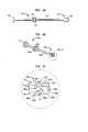
- FIG. 1 of the present applicationshow front ( FIG. 1 a ), side cutaway ( FIG. 1 b ), top ( FIG. 1 c ), perspective cutaway ( FIG. 1 d ), bottom cutaway ( FIG. 1 e ), top cutaway ( FIG. 1 f ), bottom perspective ( FIG. 1 g ), and top perspective ( FIG. 1 h ) views of an exemplary artificial intervertebral disc for use with the present invention.
- FIGS. 2 a–cshow side ( FIG. 2 a ), perspective ( FIG. 2 b ), and close-up perspective ( FIG. 2 c ) views of a wedge plate inserter/impactor of the present invention.
- FIGS. 3 a–dshow bottom ( FIG. 3 a ), side ( FIG. 3 b ), top ( FIG. 3 c ), and side cutaway ( FIG. 3 d ) views of a distal end of a wedge plate inserter/impactor of the present invention.
- FIGS. 4 a–bshow top ( FIG. 4 a ) and side ( FIG. 4 b ) views of a wedge plate inserter/impactor of the present invention holding an exemplary artificial intervertebral disc.
- FIGS. 4 c–eshow top ( FIG. 4 c ), side ( FIG. 4 d ), and side cutaway ( FIG. 4 e ) views of a distal end of a wedge plate inserter/impactor of the present invention holding an exemplary artificial intervertebral disc.
- an artificial intervertebral disce.g., artificial intervertebral disc 160
- an artificial intervertebral discfor use with the instrumentation of the present invention is referenced and described in the '356 application, and the same description is hereby incorporated by reference herein.
- the artificial intervertebral disc illustrated in FIGS. 1 a–h of the present applicationis discussed herein with reference to such figures, as an example of an artificial intervertebral disc suitable for use with the present invention.
- FIGS. 1 a–han artificial intervertabral disc of the present invention is shown in front ( FIG. 1 a ), side cutaway ( FIG. 1 b ), top ( FIG. 1 c ), side cutaway ( FIG. 1 d ), bottom cutaway ( FIG. 1 e ), top cutaway ( FIG. 1 f ), bottom perspective ( FIG. 1 g ), and top perspective ( FIG. 1 h ) views.
- FIGS. 1 a – 1 hare merely to show an example of one type of artificial intervertebral disc that is contemplated by, encompassed by, and suitable for use with, the present invention, and that such illustration and reference herein is not meant to limit the scope of the present invention or limit the uses of the present invention. Rather, any other artificial intervertebral disc (or any other orthopedic device) having suitable features for being manipulated by the instrumentation and methods described herein are contemplated by the present invention. Indeed, the features suitable for manipulation (e.g., angled flat surfaces with adjacent holes) are encompassed by the present invention, regardless of to what orthopedic device they may be applied.
- FIGS. 1 a – 1 hOther exemplary suitable artificial intervertebral discs include, but are not limited to, the artificial intervertebral discs described in the '160 application.
- the artificial intervertebral disc shown in FIGS. 1 a – 1 hhas features similar to those of these other suitable artificial intervertebral discs of the '160 application, and it should be understood that such similar features are structurally and functionally as described in the '160 application.
- Such similar featuresinclude an inwardly facing surface of the upper baseplate 164 a , and a convex structure 162 on the lower baseplate 168 b , the convex structure 162 having an inwardly facing surface 164 b.
- the features of the artificial intervertebral disce.g., the flat surfaces and accompanying holes
- the static trialse.g., the cylindrical trunks and flat surfaces and accompanying holes
- the features of the artificial intervertebral disccan be applied, individually or collectively or in various combinations, to other trials, spacers, artificial intervertebral discs or other orthopedic devices as stand-alone innovative features for enabling such trials, spacers, artificial intervertebral discs, or other orthopedic devices to be more efficiently and more effectively held and/or manipulated by the tools described herein or by other tools having similar features.
- the inventionencompasses artificial intervertebral discs, spacers, trials (static or dynamic), and/or other orthopedic devices, that have one or more of the features disclosed herein, in any combination, and that the invention is therefore not limited to artificial intervertebral discs, spacers, trials, and/or other orthopedic devices having all of the features simultaneously.
- a plurality of static trialsare provided primarily for use in determining the appropriate size of an artificial intervertebral disc to be implanted (or whether a particular size of the artificial intervertebral disc can be implanted) into the distracted intervertebral space (e.g., the artificial intervertebral disc 160 of FIGS. 1 a – 1 h ).
- a plurality of sizes of the artificial intervertebral discwould be available for each artificial intervertebral disc to be implanted. That is, preferably, a plurality of the same type of artificial intervertebral disc would be available, each of the plurality having a respective width and depth dimension combination that allows it to fit within a correspondingly dimensioned intervertebral space.
- the plurality of artificial intervertebral discscould include artificial intervertebral discs having widths being either 35 mm or 40 mm, and depths ranging from 14 mm to 18 mm in 1 mm increments, for a total of 10 discs.
- each of the plurality of static trials for use with a particular plurality of differently sized artificial intervertebral discswould have a respective width and depth dimension set corresponding to the width and depth of a respective one of the plurality of differently sized artificial intervertebral discs.
- the plurality of static trials for use with the set of artificial intervertebral discs described for examplecould include static trials having widths being either 35 mm or 40 mm, and depths ranging from 14 mm to 18 mm in 1 mm increments, for a total of 10 static trials.
- the artificial intervertebral discs and/or the static trialscan be offered in a variety of dimensions without departing from the scope of the invention, and that the dimensions specifically identified and quantified herein are merely exemplary.
- the set of static trialsneed not include the same number of trials for each artificial intervertebral disc in the set of artificial intervertebral discs, but rather, none, one, or more than one trial can be included in the trial set for any particular artificial intervertebral disc in the set.
- FIGS. 2 a – 4 eFIGS. 2 a–c side ( FIG. 2 a ), perspective ( FIG. 2 b ), and close-up perspective ( FIG. 2 c ), and perspective ( FIG. 4 d ) views of a wedge plate inserter/impactor of the present invention.
- FIGS. 3 a–dshow bottom ( FIG. 3 a ), side ( FIG. 3 b ), top ( FIG. 3 c ), and side cutaway ( FIG. 3 d ) views of a distal end of a wedge plate inserter/impactor of the present invention.
- FIGS. 4 a–bshow top ( FIG. 4 a ) and side ( FIG.
- FIGS. 4 c–eshow top ( FIG. 4 c ), side ( FIG. 4 d ), and side cutaway ( FIG. 4 e ) views of a distal end of a wedge plate inserter/impactor of the present invention holding an exemplary artificial intervertebral disc.
- FIGS. 1 a–h of the present applicationis merely to show an example of one type of artificial intervertebral disc that is contemplated by, encompassed by, and suitable for use with, the present invention, and that such illustration and reference herein is not meant to limit the scope of the present invention or limit the uses of the present invention. Rather, any other artificial intervertebral disc (or any other orthopedic device) having suitable features for being used with the instrumentation and methods described herein are contemplated by the present invention.
- the artificial intervertebral disc shown in FIG. 1 1 –h of the present applicationhas features similar to those of these other suitable artificial intervertebral discs of the '160 application, and it should be understood that such similar features are structurally and functionally as described in the '160 application.
- Such similar featuresinclude an inwardly facing surface of the upper baseplate, and a convex structure on the lower baseplate, the convex structure having an inwardly facing surface.
- the features of the artificial intervertebral disce.g., the angled flat surfaces and the inwardly facing baseplate surfaces, and accompanying holes
- the features of the artificial intervertebral disccan be applied, individually or collectively or in various combinations, to other trials, spacers, artificial intervertebral discs or other orthopedic devices as stand-alone innovative features for enabling such trials, spacers, artificial intervertebral discs, or other orthopedic devices to be more efficiently and more effectively held and/or manipulated by the tools described herein (or in the '356 application) or by other tools having suitable features.
- the inventionencompasses artificial intervertebral discs, spacers, trials (static or dynamic), and/or other orthopedic devices, that have one or more of the features disclosed herein (or in the '356 application), in any combination, and that the invention is therefore not limited to artificial intervertebral discs, spacers, trials, and/or other orthopedic devices having all of the features simultaneously.
- a plurality of sizes of the artificial intervertebral discwould be available for each artificial intervertebral disc to be implanted. That is, preferably, a plurality of the same type of artificial intervertebral disc would be available, each of the plurality having a respective width and depth dimension combination that allows it to fit within a correspondingly dimensioned intervertebral space.
- the plurality of artificial intervertebral discscould include artificial intervertebral discs having widths being either 35 mm or 40 mm, and depths ranging from 14 mm to 18 mm in 1 mm increments, for a total of 10 discs.
- the inserter/impactor 4000is provided primarily for holding, inserting, repositioning, removing, impacting, extracting, and otherwise manipulating an artificial intervertebral disc having features suitable for being manipulated by the inserter/impactor. (However, it can also be used to hold, insert, reposition, remove, impact, extract, and otherwise manipulate any other orthopedic device having suitable features therefor.
- exemplary suitable artificial intervertebral discsinclude, but are not limited to, the artificial intervertebral disc 160 described herein and the artificial intervertebral discs described in the '160 application with regard to FIGS. 8 a–y , 9 a–t , 10 a–t , 11 a–j , and 12 a–o thereof and by the accompanying descriptions therefor (e.g., embodiments identified as the first, second, third, fourth, and fifth preferred embodiments of the fourth embodiment family, etc.).
- such featuresinclude those discussed above as being suitable features on the disc 160 , namely, an anteriorly facing flat surface on the second (e.g., lower) baseplate of the trial or disc, flanked by two anteriolaterally facing flat surfaces (one on each side of the anteriorly facing flat surface), and, to provide for holding of the trial or disc for an anterior insertion approach, a hole spaced from the anteriorly facing flat surface, the hole having a longitudinal axis parallel to the anteriorly facing flat surface.
- such features suitable for being manipulated by the inserter/impactorsuch features further include the inwardly facing surfaces of the baseplates of the disc.
- the inserter/impactor 4000includes a shaft 4020 having a distal end 4040 that has angled flat surfaces 4200 a–c corresponding to and fittable against angled flat surfaces of the artificial intervertebral disc (e.g., the surfaces 180 a–c of the artificial intervertebral disc 160 ) to be implanted.
- the distal end 4040has angled flat surfaces 4200 d–f corresponding to and fittable against angled flat surfaces of the artificial intervertebral disc. (e.g., the surfaces 180 d–f of the artificial intervertebral disc 160 ) to be implanted.
- the distal end 4040has a wedge-shaped extension 4042 including upper 4200 g and lower 4200 h wedge surfaces corresponding to and fittable against the inwardly facing surfaces of the artificial intervertebral disc (e.g., the lower surface 164 a of the upper baseplate 168 a of the disc 160 , and the upper surface 164 b of the lower baseplate 168 b of the disc 160 , respectively) to be implanted.
- the artificial intervertebral disce.g., the lower surface 164 a of the upper baseplate 168 a of the disc 160 , and the upper surface 164 b of the lower baseplate 168 b of the disc 160 , respectively
- the inserter/impactor 4000holds the disc 160 in a preferred position with respect to the inserter/impactor 4000 .
- the surfaces of the wedge-shaped extension 4042can be modified within the scope of the present invention to hold the disc 160 (or another orthopedic device) at positions other than those illustrated herein.
- the preferred positionis with the baseplates 168 a,b of the disc 160 angle at 15 degrees of lordosis with respect to one another.
- the upper and lower surfaces (e.g., 4200 g and 4200 h ) of the wedge-shaped extension 4042protrude from the distal end 4040 and are formed to hold the baseplates 168 a,b such that they are angled at 15 degrees of lordosis with respect to one another.
- a surface (e.g., lower surface 4200 h ) of the wedge-shape extension 4042 that mates with an inwardly facing surface of a baseplate (e.g., the lower baseplate 168 b ) of a disc (e.g., 160 )may be correspondingly shaped (e.g., curved or flat) for interaction or mating with the disc baseplate (e.g., the lower surface 4200 h of the wedge-shaped extension as illustrated is curved to accommodate the surface of the shield of the disc).
- the forward surface 4200 i of the wedge-shaped extension 4042has a concave curvature towards the shaft 4020 of the inserter/impactor 4000 , also for accommodating the curvature of the surface of the shield of the disc.
- the wedge surfaces of the distal end 4040protrude from a distance midway with respect to the top and bottom of the distal end 4040 and span (e.g., right to left or vice-versa) the entire distal face of the distal end 4040 , and the surfaces 4200 d–f above the wedge on the distal end 4040 are respectively perpendicular to the wedge's upper surface 4200 g such that each is disposed in parallel with its respective corresponding surface of the disc 160 when the disc 160 is held by the inserter/impactor 4000 at the appropriate lordosis angle.
- the wedge-shaped extension 4042is designed and shaped to fit with its antero-lateral confronting surfaces ( 4200 d,f and 4200 a,c ) tightly against the correspondingly antero-laterally facing surfaces ( 180 d,f and 180 a,c ) of the disc 160 , but such that its anterior confronting surfaces ( 4200 e and 4200 b ) are slightly spaced from the anteriorly facing surfaces ( 180 d and 180 b ) of the disc 160 , when the disc is held by the inserter/impactor 4000 .
- anterior confronting surfaces ( 4200 e and 4200 b )can be slightly greater in length than the corresponding anteriorly facing surfaces ( 180 e and 180 b ) of the disc baseplates, while still being angled with respect to the antero-lateral confronting surfaces ( 4200 d,f and 4200 a,c ) at the same angle the antero-laterally facing surfaces ( 180 d,f and 180 a,c ) of the disc baseplates are angled with respect to the anteriorly facing surfaces ( 180 e and 180 b ) of the disc.
- the increased length of the anterior confronting surfaces on the wedge extensionresults in the slight clearance between the anteriorly facing surfaces ( 180 e and 180 b ) of the disc and the corresponding anterior confronting surface ( 4200 e and 4200 b ) of the wedged distal end, thereby ensuring that the disc will be fully seated against the antero-lateral confronting surfaces of the distal end despite possible manufacturing, material or other inevitable variations in tolerances of the artificial intervertebral disc or the inserter/impactor.
- this fittingincreases the mechanical advantage toward repositioning the disc in the intervertebral space.
- the anterior confronting surfaces ( 4200 e and 4200 b )should also be longer than the antero-laterally facing surfaces ( 180 d,f and 180 a,c ) of the disc, so that a similar fitting occurs when the disc is held from the antero-lateral angles.
- the primary confronting surfaces (e.g., the anterior confronting surfaces) of the inserter/impactorare preferably slightly longer than the primary confronted surfaces (e.g., anteriorly facing surfaces) of the disc for any given holding orientation.
- the inserter/impactor 4000includes a holding pin 4080 that extends from the wedge 4042 along a longitudinal axis of the shaft 4020 , the pin 4080 having a distal end 4100 that is bent downwardly.
- the holding pin 4080is spring loaded (e.g., by a spring 4090 ) in a central channel of the shaft 4020 , so that it is biased toward the shaft 4020 (preferably, the bent end 4100 of the pin 4080 prevents it from entering the central channel).
- the holding pin 4080is restricted from upwardly lateral movement with respect to the distal end of the inserter/impactor by the presence of the wedge-shaped extension 4042 of the distal end 4040 of the inserter/impactor 4000 .
- the holding pin 4080is preferably heat treated (e.g., cold formed) to increase material quality (e.q., strength).
- a flange 4110mechanically connected to the pin 4080 and translating adjacent the shaft 4020 , can be pushed distally to overcome the bias of the spring 4090 to space the pin 4080 away from the wedge 4042 .
- the pin 4080In this extended position, the pin 4080 can be inserted in a hole (e.g., 182 b ) in the baseplate (e.g., 168 b ) of the artificial intervertebral disc (e.g., 160 ).
- the anteriorly facing surface 180 e of the baseplate 168 ais pulled against the upper central flat surface 4200 e of the inserter/impactor 4000 and the anterioloaterally facing flat surfaces 180 d,f of the artificial intervertebral disc 160 is pulled against the other corresponding flat surfaces 4200 d,f of the inserter/impactor 4000 .
- the upper and lower wedge surfaces( 4200 g,h ) interfere between the inwardly facing surfaces 164 a,b of the disc baseplates, causing the baseplate to be angled at a 15 degree lordosis angle, with the lower surface 164 a of the upper baseplate 168 a held against the upper surface 4200 g , and the upper surface of the shield being held against the lower surface 4200 h , as best shown in FIGS. 4 a–e.
- a knob 4120threaded on the shaft 4020 , can be rotated about the longitudinal axis of the shaft 4020 to push the flange 4110 farther proximally, to pull the pin 4080 tighter and therefore lock its position (the interference of the threads of the knob-shaft interface prevents the knob 4120 from moving distally unless the knob 4120 is reverse rotated to effect that result) to more securely hold the baseplate 168 b , and reverse rotated to unlock and loosen the pin 4080 .
- the holding of the disc in this mannerallows for some repositioning of the disc in the intervertebral space via rotation of the disc in either direction about the longitudinal or latitudinal axis of the intervertebral space.
- the flat surfaces 180 a–care more closely confronted by the angled flat surfaces 4200 a–c of the inserter/impactor 4000 , compared with the flat surfaces 180 d–f being less closely confronted by the angled flat surfaces 4200 d–f of the inserter/impactor 4000 .
- the structure of the artificial intervertebral disc 160 having the flat surfaces 180 d–f(e.g., the upper baseplate 168 a ) has slightly more rotation and angulation freedom relative to the inserter/impactor 4000 when being held, compared to the structure of the artificial intervertebral disc 160 having the flat surfaces 180 a–c (e.g., the lower baseplate 168 b ).
- each disc 160also includes two additional holes 182 a and 182 c , one (e.g., 182 a ) spaced apart from one of the anteriolaterally facing flat surfaces (e.g. 180 a ), and the other (e.g. 182 c ) spaced apart from the other of the anteriolaterally facing flat surfaces (e.g. 180 c ).
- operation of the inserter/impactor 4000can fit the holding pin 4080 into either of these two additional holes 182 a or 182 c , and hold the associated anteriolaterally facing flat surface (the one associated with the hole into which the pin 4080 is fit) of the disc 160 against the flat surface of the inserter/impactor 4000 opposite the pin 4080 .
- the angle separating the anteriorly facing flat surface of the disc 160 and one of the anteriolaterally facing flat surfaces of the disc 160is equal to the angle separating the anteriorly facing flat surface and the other of the anteriolaterally facing flat surfaces.
- the surfacesare angled with respect to one another at an angle of 33.4 degrees.
- a trial or disccan have angled surfaces (and corresponding holes) along the entire perimeter of one or both of the baseplates, and thus enable the surgeon to engage the trial or disc from a number of angles, including anterior, posterior, lateral, anteriolateral, and posteriolateral angles.
- the inserter/impactor 4000further includes at a proximal end a cap 4140 for use as an impact surface if the disc 160 must be impacted further into the intervertebral space after insertion, or forcibly extracted from the intervertebral space.
- a malletcan be used to strike the cap 4140 (in a distal direction for impaction, or in a proximal direction (using the flange of the cap 4140 ) for extraction). It should be noted a striking of the cap 4140 will translate the striking force to the baseplates through the shaft 4020 and the flat surfaces, but will not damage the holding pin 4080 because the holding pin 4080 is spring loaded in the central channel and thus buffered from the striking force thereby.
- the distal end 4040 of the inserter/impactor 4000further preferably includes at least one vertebral body stop 4202 that protrudes longitudinally with respect to the shaft 4020 , from the surfaces of the distal end.
- the stopshelp prevent the inserter/impactor from being used to insert the disc (or other orthopedic device) too far into the intervertebral space.
- the inserter/impactor 4000can be used to grip the artificial intervertebral disc to be implanted, and hold the same during insertion and/or removal of the same, and is useful for a variety of surgical approach angles.
Landscapes
- Health & Medical Sciences (AREA)
- Engineering & Computer Science (AREA)
- Biomedical Technology (AREA)
- Orthopedic Medicine & Surgery (AREA)
- Transplantation (AREA)
- Neurology (AREA)
- Heart & Thoracic Surgery (AREA)
- Oral & Maxillofacial Surgery (AREA)
- Cardiology (AREA)
- Vascular Medicine (AREA)
- Life Sciences & Earth Sciences (AREA)
- Animal Behavior & Ethology (AREA)
- General Health & Medical Sciences (AREA)
- Public Health (AREA)
- Veterinary Medicine (AREA)
- Physical Education & Sports Medicine (AREA)
- Prostheses (AREA)
Abstract
Description
Claims (8)
Priority Applications (29)
| Application Number | Priority Date | Filing Date | Title |
|---|---|---|---|
| US10/425,267US7235081B2 (en) | 2001-07-16 | 2003-04-29 | Wedge plate inserter/impactor and related methods for use in implanting an artificial intervertebral disc |
| US10/663,492US7223291B2 (en) | 2001-07-16 | 2003-09-16 | Intervertebral spacer device having engagement hole pairs for manipulation using a surgical tool |
| US10/663,488US7811287B2 (en) | 2001-07-16 | 2003-09-16 | Intervertebral spacer device having an engagement hole for a tool with an extendable post |
| US10/663,493US8366775B2 (en) | 2001-07-16 | 2003-09-16 | Intervertebral spacer device having an angled perimeter for manipulation using a surgical tool |
| US10/663,487US7635368B2 (en) | 2001-07-16 | 2003-09-16 | Intervertebral spacer device having simultaneously engageable angled perimeters for manipulation using a surgical tool |
| CA2632115ACA2632115C (en) | 2002-10-29 | 2003-09-16 | Instrumentation, methods and features for use in implanting an artificial intervertebral disc |
| PCT/US2003/028957WO2004039291A1 (en) | 2002-10-29 | 2003-09-16 | Instrumentation, methods, and features for use in implanting an artificial intervertebral disc |
| JP2005501875AJP4654125B2 (en) | 2002-10-29 | 2003-09-16 | Instruments, methods, and functions for use in implanting an artificial disc |
| CA2632125ACA2632125C (en) | 2002-10-29 | 2003-09-16 | Instrumentation, methods and features for use in implanting an artificial intervertebral disc |
| EP03749686AEP1555966A4 (en) | 2002-10-29 | 2003-09-16 | Instrumentation, methods, and features for use in implanting an artificial intervertebral disc |
| AU2003267215AAU2003267215B2 (en) | 2002-10-29 | 2003-09-16 | Instrumentation, methods, and features for use in implanting an artificial intervertebral disc |
| US10/663,486US7491241B2 (en) | 2001-07-16 | 2003-09-16 | Intervertebral spacer device having recessed notch pairs for manipulation using a surgical tool |
| CA002503848ACA2503848C (en) | 2002-10-29 | 2003-09-16 | Instrumentation, methods, and features for use in implanting an artificial intervertebral disc |
| US10/782,981US7575576B2 (en) | 2001-07-16 | 2004-02-20 | Wedge ramp distractor and related methods for use in implanting artificial intervertebral discs |
| US10/783,152US20050143747A1 (en) | 2001-07-16 | 2004-02-20 | Parallel distractor and related methods for use in implanting an artificial intervertebral disc |
| US10/784,645US8858564B2 (en) | 2001-02-15 | 2004-02-23 | Wedge plate inserter/impactor and related methods for use in implanting an artificial intervertebral disc |
| US11/657,268US20070123906A1 (en) | 2001-07-16 | 2007-01-24 | Inserter/impactor for implanting an artificial intervertebral disc |
| US11/716,360US8303659B2 (en) | 2001-07-16 | 2007-03-09 | Intervertebral spacer device having engagement hole pairs |
| US11/789,327US20070198092A1 (en) | 2001-07-16 | 2007-04-24 | System for inserting artificial intervertebral discs |
| US12/321,562US8940047B2 (en) | 2001-02-15 | 2009-01-22 | Intervertebral spacer device having recessed notch pairs for manipulation using a surgical tool |
| AU2009200850AAU2009200850B2 (en) | 2002-10-29 | 2009-03-03 | Instrumentation, methods, and features for use in implanting an artificial intervertebral disc |
| JP2009151399AJP4979741B2 (en) | 2002-10-29 | 2009-06-25 | Intervertebral spacer instrument and tool set for use in implanting an artificial disc |
| US12/501,889US9132020B2 (en) | 2001-07-16 | 2009-07-13 | Wedge ramp distractor for use in implanting artificial intervertebral discs |
| US12/938,080US8545564B2 (en) | 2001-07-16 | 2010-11-02 | Intervertebral spacer device having an articulation member and housing |
| AU2011200915AAU2011200915B2 (en) | 2002-10-29 | 2011-03-02 | Instrumentation, methods, and features for use in implanting an artificial intervertebral disc |
| US14/340,091US9814596B2 (en) | 2001-07-16 | 2014-07-24 | Method of orienting an intervertebral spacer device having recessed notch pairs by using a surgical tool |
| US15/014,803US9700429B2 (en) | 2001-07-16 | 2016-02-03 | Intervertebral spacer device having recessed notch pairs for manipulation using a surgical tool |
| US15/618,566US20170273805A1 (en) | 2001-07-16 | 2017-06-09 | Intervertebral spacer device having recessed notch pairs for manipulation using a surgical tool |
| US15/726,958US20180028330A1 (en) | 2001-07-16 | 2017-10-06 | Intervertebral spacer device having recessed notch pairs for manipulation using a surgical tool |
Applications Claiming Priority (11)
| Application Number | Priority Date | Filing Date | Title |
|---|---|---|---|
| US09/906,119US6607559B2 (en) | 2001-07-16 | 2001-07-16 | Trial intervertebral distraction spacers |
| US09/968,046US20020111687A1 (en) | 2001-02-15 | 2001-10-01 | Intervertebral spacer device utilizing a belleville washer having radially extending grooves |
| US09/970,479US6669730B2 (en) | 2001-02-15 | 2001-10-04 | Intervertebral spacer device utilizing a spirally slotted belleville washer having radially extending grooves |
| US09/982,148US6673113B2 (en) | 2001-10-18 | 2001-10-18 | Intervertebral spacer device having arch shaped spring elements |
| US10/128,619US6863689B2 (en) | 2001-07-16 | 2002-04-23 | Intervertebral spacer having a flexible wire mesh vertebral body contact element |
| US10/140,153US20030069642A1 (en) | 2001-10-04 | 2002-05-07 | Artificial intervertebral disc having a flexible wire mesh vertebral body contact element |
| US10/151,280US7604664B2 (en) | 2001-07-16 | 2002-05-20 | Spinal baseplates with ball joint coupling and a retaining member |
| US10/175,417US7563285B2 (en) | 2001-07-16 | 2002-06-19 | Artificial intervertebral disc utilizing a ball joint coupling |
| US10/256,160US6989032B2 (en) | 2001-07-16 | 2002-09-26 | Artificial intervertebral disc |
| US10/282,356US7169182B2 (en) | 2001-07-16 | 2002-10-29 | Implanting an artificial intervertebral disc |
| US10/425,267US7235081B2 (en) | 2001-07-16 | 2003-04-29 | Wedge plate inserter/impactor and related methods for use in implanting an artificial intervertebral disc |
Related Parent Applications (2)
| Application Number | Title | Priority Date | Filing Date |
|---|---|---|---|
| US10/282,356Continuation-In-PartUS7169182B2 (en) | 2001-02-15 | 2002-10-29 | Implanting an artificial intervertebral disc |
| US10/309,585Continuation-In-PartUS7115132B2 (en) | 2001-02-15 | 2002-12-04 | Static trials and related instruments and methods for use in implanting an artificial intervertebral disc |
Related Child Applications (11)
| Application Number | Title | Priority Date | Filing Date |
|---|---|---|---|
| US10/309,585Continuation-In-PartUS7115132B2 (en) | 2001-02-15 | 2002-12-04 | Static trials and related instruments and methods for use in implanting an artificial intervertebral disc |
| US10/663,492Continuation-In-PartUS7223291B2 (en) | 2001-02-15 | 2003-09-16 | Intervertebral spacer device having engagement hole pairs for manipulation using a surgical tool |
| US10/663,486Continuation-In-PartUS7491241B2 (en) | 2001-07-16 | 2003-09-16 | Intervertebral spacer device having recessed notch pairs for manipulation using a surgical tool |
| US10/663,487Continuation-In-PartUS7635368B2 (en) | 2001-07-16 | 2003-09-16 | Intervertebral spacer device having simultaneously engageable angled perimeters for manipulation using a surgical tool |
| US10/663,487ContinuationUS7635368B2 (en) | 2001-07-16 | 2003-09-16 | Intervertebral spacer device having simultaneously engageable angled perimeters for manipulation using a surgical tool |
| US10/663,493Continuation-In-PartUS8366775B2 (en) | 2001-07-16 | 2003-09-16 | Intervertebral spacer device having an angled perimeter for manipulation using a surgical tool |
| US10/663,488Continuation-In-PartUS7811287B2 (en) | 2001-07-16 | 2003-09-16 | Intervertebral spacer device having an engagement hole for a tool with an extendable post |
| US10/782,981Continuation-In-PartUS7575576B2 (en) | 2001-02-15 | 2004-02-20 | Wedge ramp distractor and related methods for use in implanting artificial intervertebral discs |
| US10/784,645ContinuationUS8858564B2 (en) | 2001-02-15 | 2004-02-23 | Wedge plate inserter/impactor and related methods for use in implanting an artificial intervertebral disc |
| US11/657,268ContinuationUS20070123906A1 (en) | 2001-07-16 | 2007-01-24 | Inserter/impactor for implanting an artificial intervertebral disc |
| US11/789,327ContinuationUS20070198092A1 (en) | 2001-07-16 | 2007-04-24 | System for inserting artificial intervertebral discs |
Publications (2)
| Publication Number | Publication Date |
|---|---|
| US20030229358A1 US20030229358A1 (en) | 2003-12-11 |
| US7235081B2true US7235081B2 (en) | 2007-06-26 |
Family
ID=46282287
Family Applications (1)
| Application Number | Title | Priority Date | Filing Date |
|---|---|---|---|
| US10/425,267Expired - Fee RelatedUS7235081B2 (en) | 2001-02-15 | 2003-04-29 | Wedge plate inserter/impactor and related methods for use in implanting an artificial intervertebral disc |
Country Status (1)
| Country | Link |
|---|---|
| US (1) | US7235081B2 (en) |
Cited By (38)
| Publication number | Priority date | Publication date | Assignee | Title |
|---|---|---|---|---|
| US20040034422A1 (en)* | 2001-07-16 | 2004-02-19 | Errico Joseph P. | Intervertebral spacer device having a circumferentially buried wire mesh endplate attachment device |
| US20040153158A1 (en)* | 2001-07-16 | 2004-08-05 | Errico Joseph P. | Intervertebral spacer device having an angled perimeter for manipulation using a surgical tool |
| US20040167536A1 (en)* | 2001-07-16 | 2004-08-26 | Errico Joseph P. | Instrumentation for properly seating an artificial intervertebral disc in an intervertebral space |
| US20070123906A1 (en)* | 2001-07-16 | 2007-05-31 | Spinecore, Inc. | Inserter/impactor for implanting an artificial intervertebral disc |
| US20070142843A1 (en)* | 2005-12-21 | 2007-06-21 | Justin Dye | Articulated delivery instrument |
| US20070156243A1 (en)* | 2001-07-16 | 2007-07-05 | Spinecore, Inc. | Intervertebral spacer device having engagement hole pairs |
| US20070162139A1 (en)* | 2001-07-16 | 2007-07-12 | Ralph James D | Trial intervertebral distraction spacers |
| US20070225726A1 (en)* | 2006-03-23 | 2007-09-27 | Justin Dye | Instruments for delivering spinal implants |
| US20090270870A1 (en)* | 2008-04-24 | 2009-10-29 | Rafail Zubok | Dynamic distractor |
| US20090312765A1 (en)* | 2001-07-16 | 2009-12-17 | Spinecore, Inc. | Wedge Ramp Distractor for use in Implanting Artificial Intervertebral Discs |
| US7771478B2 (en) | 2003-04-04 | 2010-08-10 | Theken Spine, Llc | Artificial disc prosthesis |
| US7815648B2 (en) | 2004-06-02 | 2010-10-19 | Facet Solutions, Inc | Surgical measurement systems and methods |
| US20110004314A1 (en)* | 2009-07-02 | 2011-01-06 | Baynham Matthew G | Intervertebral Spacer |
| US20110046744A1 (en)* | 2001-07-16 | 2011-02-24 | Spinecore, Inc. | Intervertebral spacer device having recessed notch pairs for manipulation using a surgical tool |
| US7914560B2 (en) | 2004-02-17 | 2011-03-29 | Gmedelaware 2 Llc | Spinal facet implant with spherical implant apposition surface and bone bed and methods of use |
| US8029568B2 (en) | 2001-10-18 | 2011-10-04 | Spinecore, Inc. | Intervertebral spacer device having a slotted partial circular domed arch strip spring |
| US8092539B2 (en) | 2001-10-01 | 2012-01-10 | Spinecore, Inc. | Intervertebral spacer device having a belleville washer with concentric grooves |
| US8100972B1 (en) | 2007-07-02 | 2012-01-24 | Theken Spine, Llc | Spinal cage having deployable member |
| US8206418B2 (en) | 2007-01-10 | 2012-06-26 | Gmedelaware 2 Llc | System and method for facet joint replacement with detachable coupler |
| US8267997B2 (en) | 2007-11-12 | 2012-09-18 | Theken Spine, Llc | Vertebral interbody compression implant |
| US8292958B1 (en) | 2007-07-02 | 2012-10-23 | Theken Spine, Llc | Spinal cage having deployable member |
| US20120310293A1 (en)* | 2008-10-16 | 2012-12-06 | Aesculap Implant Systems, Llc. | Surgical instrument and method of use for inserting an implant between two bones |
| US8506636B2 (en) | 2006-09-08 | 2013-08-13 | Theken Spine, Llc | Offset radius lordosis |
| US8545562B1 (en) | 2007-07-02 | 2013-10-01 | Theken Spine, Llc | Deployable member for use with an intervertebral cage |
| US8777994B2 (en) | 2004-06-02 | 2014-07-15 | Gmedelaware 2 Llc | System and method for multiple level facet joint arthroplasty and fusion |
| US8864829B1 (en) | 2007-07-02 | 2014-10-21 | Theken Spine, Llc | Spinal cage having deployable member |
| US20150025639A1 (en)* | 2009-11-05 | 2015-01-22 | DePuy Synthes Products, LLC | Self-pivoting spinal implant and associated instrumentation |
| US9034046B2 (en) | 2007-10-30 | 2015-05-19 | Aesculap Implant Systems, Llc | Vertebral body replacement device and method for use to maintain a space between two vertebral bodies within a spine |
| US9451940B2 (en) | 2008-12-26 | 2016-09-27 | Pantheon Spinal, Llc | Method of retroperitoneal lateral insertion of spinal implants |
| US9687360B2 (en) | 2009-07-02 | 2017-06-27 | Atlas Spine, Inc. | Implantable spinal insert system |
| US10022245B2 (en) | 2012-12-17 | 2018-07-17 | DePuy Synthes Products, Inc. | Polyaxial articulating instrument |
| US10342674B2 (en) | 2007-07-02 | 2019-07-09 | Theken Spine, Llc | Spinal cage having deployable member |
| US10716553B2 (en) | 2017-04-19 | 2020-07-21 | Pantheon Spinal, Llc | Spine surgery retractor system and related methods |
| US10966843B2 (en) | 2017-07-18 | 2021-04-06 | DePuy Synthes Products, Inc. | Implant inserters and related methods |
| US11045331B2 (en) | 2017-08-14 | 2021-06-29 | DePuy Synthes Products, Inc. | Intervertebral implant inserters and related methods |
| US11096802B2 (en) | 2018-03-03 | 2021-08-24 | K2M, Inc. | Intervertebral trial with marker |
| US11452618B2 (en) | 2019-09-23 | 2022-09-27 | Dimicron, Inc | Spinal artificial disc removal tool |
| US12186201B2 (en) | 2007-07-02 | 2025-01-07 | Theken Spine, Llc | Spinal cage having deployable member |
Families Citing this family (104)
| Publication number | Priority date | Publication date | Assignee | Title |
|---|---|---|---|---|
| US20080039859A1 (en)* | 1997-01-02 | 2008-02-14 | Zucherman James F | Spine distraction implant and method |
| US7604664B2 (en)* | 2001-07-16 | 2009-10-20 | Spinecore, Inc. | Spinal baseplates with ball joint coupling and a retaining member |
| US7235081B2 (en) | 2001-07-16 | 2007-06-26 | Spinecore, Inc. | Wedge plate inserter/impactor and related methods for use in implanting an artificial intervertebral disc |
| US6669730B2 (en) | 2001-02-15 | 2003-12-30 | Spinecore, Inc. | Intervertebral spacer device utilizing a spirally slotted belleville washer having radially extending grooves |
| US7160327B2 (en) | 2001-07-16 | 2007-01-09 | Spinecore, Inc. | Axially compressible artificial intervertebral disc having limited rotation using a captured ball and socket joint with a solid ball and compression locking post |
| US7118599B2 (en) | 2001-07-16 | 2006-10-10 | Spinecore, Inc. | Artificial intervertebral disc |
| US20070198092A1 (en)* | 2001-07-16 | 2007-08-23 | Spinecore, Inc. | System for inserting artificial intervertebral discs |
| US7713302B2 (en) | 2001-10-01 | 2010-05-11 | Spinecore, Inc. | Intervertebral spacer device utilizing a spirally slotted belleville washer having radially spaced concentric grooves |
| US20090177283A9 (en)* | 2001-10-01 | 2009-07-09 | Ralph James D | Intervertebral spacer device utilizing a spirally slotted belleville washer and a rotational mounting |
| US7208014B2 (en)* | 2001-10-01 | 2007-04-24 | Spinecore, Inc. | Intervertebral spacer device utilizing a belleville washer having radially extending grooves |
| US8038713B2 (en) | 2002-04-23 | 2011-10-18 | Spinecore, Inc. | Two-component artificial disc replacements |
| US20080027548A9 (en) | 2002-04-12 | 2008-01-31 | Ferree Bret A | Spacerless artificial disc replacements |
| US6706068B2 (en) | 2002-04-23 | 2004-03-16 | Bret A. Ferree | Artificial disc replacements with natural kinematics |
| US8388684B2 (en) | 2002-05-23 | 2013-03-05 | Pioneer Signal Technology, Inc. | Artificial disc device |
| AU2003226586A1 (en) | 2002-09-19 | 2004-04-08 | Malan De Villiers | Intervertebral prosthesis |
| EP1558184A2 (en)* | 2002-10-08 | 2005-08-03 | SDGI Holdings, Inc. | Insertion device and techniques for orthopaedic implants |
| WO2004066884A1 (en) | 2003-01-31 | 2004-08-12 | Spinalmotion, Inc. | Intervertebral prosthesis placement instrument |
| ZA200506029B (en) | 2003-01-31 | 2006-10-25 | Spinalmotion Inc | Spinal Midline Indicator |
| US6908484B2 (en) | 2003-03-06 | 2005-06-21 | Spinecore, Inc. | Cervical disc replacement |
| US7105024B2 (en) | 2003-05-06 | 2006-09-12 | Aesculap Ii, Inc. | Artificial intervertebral disc |
| US7291173B2 (en) | 2003-05-06 | 2007-11-06 | Aesculap Ii, Inc. | Artificial intervertebral disc |
| DE10324108B3 (en)* | 2003-05-21 | 2005-01-27 | Aesculap Ag & Co. Kg | Backbone implant is inserted with contracted contact disc which is expanded to optimum area following insertion |
| US10052211B2 (en) | 2003-05-27 | 2018-08-21 | Simplify Medical Pty Ltd. | Prosthetic disc for intervertebral insertion |
| US7442211B2 (en) | 2003-05-27 | 2008-10-28 | Spinalmotion, Inc. | Intervertebral prosthetic disc |
| US7575599B2 (en) | 2004-07-30 | 2009-08-18 | Spinalmotion, Inc. | Intervertebral prosthetic disc with metallic core |
| DE10330698B4 (en) | 2003-07-08 | 2005-05-25 | Aesculap Ag & Co. Kg | Intervertebral implant |
| DE20310433U1 (en) | 2003-07-08 | 2003-09-04 | Aesculap AG & Co. KG, 78532 Tuttlingen | Surgical device for inserting dual component implant into appropriate space at spine, comprising particularly shaped holding area |
| DE10339170B4 (en) | 2003-08-22 | 2009-10-15 | Aesculap Ag | Intervertebral implant |
| US7625379B2 (en)* | 2004-01-26 | 2009-12-01 | Warsaw Orthopedic, Inc. | Methods and instrumentation for inserting intervertebral grafts and devices |
| EP2113227B1 (en) | 2004-02-04 | 2015-07-29 | LDR Medical | Intervertebral disc prosthesis |
| US7468076B2 (en) | 2004-02-20 | 2008-12-23 | Spinecore, Inc. | Artificial intervertebral disc having a universal joint |
| US7393361B2 (en) | 2004-02-20 | 2008-07-01 | Spinecore, Inc. | Artificial intervertebral disc having a bored semispherical bearing with a compression locking post and retaining caps |
| DE202004009542U1 (en) | 2004-06-16 | 2004-08-12 | Aesculap Ag & Co. Kg | Artificial intervertebral disk, comprising core with intensely curved upper and less curved lower surface |
| US7294134B2 (en)* | 2004-07-28 | 2007-11-13 | Weber Instrumente Gmbh | Surgical instrument for the introduction of a multi-component intervertebral prosthesis |
| US7585326B2 (en) | 2004-08-06 | 2009-09-08 | Spinalmotion, Inc. | Methods and apparatus for intervertebral disc prosthesis insertion |
| US8414648B2 (en) | 2004-08-09 | 2013-04-09 | Si-Bone Inc. | Apparatus, systems, and methods for achieving trans-iliac lumbar fusion |
| US20070156241A1 (en) | 2004-08-09 | 2007-07-05 | Reiley Mark A | Systems and methods for the fixation or fusion of bone |
| US20180228621A1 (en) | 2004-08-09 | 2018-08-16 | Mark A. Reiley | Apparatus, systems, and methods for the fixation or fusion of bone |
| US9662158B2 (en) | 2004-08-09 | 2017-05-30 | Si-Bone Inc. | Systems and methods for the fixation or fusion of bone at or near a sacroiliac joint |
| US9949843B2 (en) | 2004-08-09 | 2018-04-24 | Si-Bone Inc. | Apparatus, systems, and methods for the fixation or fusion of bone |
| US8388667B2 (en) | 2004-08-09 | 2013-03-05 | Si-Bone, Inc. | Systems and methods for the fixation or fusion of bone using compressive implants |
| US20060036251A1 (en) | 2004-08-09 | 2006-02-16 | Reiley Mark A | Systems and methods for the fixation or fusion of bone |
| US8425570B2 (en) | 2004-08-09 | 2013-04-23 | Si-Bone Inc. | Apparatus, systems, and methods for achieving anterior lumbar interbody fusion |
| JP2006068086A (en)* | 2004-08-31 | 2006-03-16 | Takiron Co Ltd | Artificial spinal disk insertion tool and tool set |
| US20060149284A1 (en)* | 2004-12-15 | 2006-07-06 | Sdgi Holdings, Inc. | Insertion device and method for inserting a member within the body |
| US8083797B2 (en) | 2005-02-04 | 2011-12-27 | Spinalmotion, Inc. | Intervertebral prosthetic disc with shock absorption |
| US20060241641A1 (en)* | 2005-04-22 | 2006-10-26 | Sdgi Holdings, Inc. | Methods and instrumentation for distraction and insertion of implants in a spinal disc space |
| US8777959B2 (en) | 2005-05-27 | 2014-07-15 | Spinecore, Inc. | Intervertebral disc and insertion methods therefor |
| US20060287728A1 (en)* | 2005-06-21 | 2006-12-21 | Mokhtar Mourad B | System and method for implanting intervertebral disk prostheses |
| FR2891135B1 (en) | 2005-09-23 | 2008-09-12 | Ldr Medical Sarl | INTERVERTEBRAL DISC PROSTHESIS |
| WO2007121320A2 (en) | 2006-04-12 | 2007-10-25 | Spinalmotion, Inc. | Posterior spinal device and method |
| US7976550B2 (en)* | 2006-08-10 | 2011-07-12 | Pioneer Surgical Technology | Insertion instrument for artificial discs |
| US8409213B2 (en)* | 2006-08-10 | 2013-04-02 | Pioneer Surgical Technology, Inc. | Insertion instrument for artificial discs |
| US8118872B2 (en) | 2006-08-10 | 2012-02-21 | Pioneer Surgical Technology, Inc. | System and methods for inserting a spinal disc device into an intervertebral space |
| US8414616B2 (en) | 2006-09-12 | 2013-04-09 | Pioneer Surgical Technology, Inc. | Mounting devices for fixation devices and insertion instruments used therewith |
| US8454621B2 (en)* | 2006-09-19 | 2013-06-04 | Warsaw Orthopedic, Inc. | Instruments and methods for spinal implant revision |
| US8372084B2 (en)* | 2006-09-22 | 2013-02-12 | Pioneer Surgical Technology, Inc. | System and methods for inserting a spinal disc device into an intervertebral space |
| US8486081B2 (en) | 2007-07-23 | 2013-07-16 | DePuy Synthes Products, LLC | Implant insertion device and method |
| US20090043391A1 (en) | 2007-08-09 | 2009-02-12 | Spinalmotion, Inc. | Customized Intervertebral Prosthetic Disc with Shock Absorption |
| US20090105834A1 (en) | 2007-10-22 | 2009-04-23 | Spinalmotion, Inc. | Dynamic Spacer Device and Method for Spanning a Space Formed upon Removal of an Intervertebral Disc |
| AU2009205679B2 (en) | 2008-01-18 | 2013-12-05 | Spinecore, Inc. | Instruments and methods for inserting artificial intervertebral implants |
| US8088163B1 (en) | 2008-02-06 | 2012-01-03 | Kleiner Jeffrey B | Tools and methods for spinal fusion |
| US20090222011A1 (en)* | 2008-02-28 | 2009-09-03 | Warsaw Orthopedic, Inc. | Targeting surgical instrument for use in spinal disc replacement and methods for use in spinal disc replacement |
| US8764833B2 (en) | 2008-03-11 | 2014-07-01 | Spinalmotion, Inc. | Artificial intervertebral disc with lower height |
| US9034038B2 (en) | 2008-04-11 | 2015-05-19 | Spinalmotion, Inc. | Motion limiting insert for an artificial intervertebral disc |
| EP2278941A1 (en) | 2008-05-05 | 2011-02-02 | Spinalmotion Inc. | Polyaryletherketone artificial intervertebral disc |
| US20210378834A1 (en) | 2008-05-22 | 2021-12-09 | Spinal Surgical Strategies, Inc., A Nevada Corporation D/B/A Kleiner Device Labs | Spinal fusion cage system with inserter |
| US9220603B2 (en) | 2008-07-02 | 2015-12-29 | Simplify Medical, Inc. | Limited motion prosthetic intervertebral disc |
| EP2299944A4 (en) | 2008-07-17 | 2013-07-31 | Spinalmotion Inc | SYSTEM FOR INSTALLING ARTIFICIAL INTERVERTEBRAL DISCS |
| EP2299941A1 (en) | 2008-07-18 | 2011-03-30 | Spinalmotion Inc. | Posterior prosthetic intervertebral disc |
| US8366748B2 (en) | 2008-12-05 | 2013-02-05 | Kleiner Jeffrey | Apparatus and method of spinal implant and fusion |
| US9247943B1 (en) | 2009-02-06 | 2016-02-02 | Kleiner Intellectual Property, Llc | Devices and methods for preparing an intervertebral workspace |
| US20170238984A1 (en) | 2009-09-18 | 2017-08-24 | Spinal Surgical Strategies, Llc | Bone graft delivery device with positioning handle |
| US10245159B1 (en) | 2009-09-18 | 2019-04-02 | Spinal Surgical Strategies, Llc | Bone graft delivery system and method for using same |
| US10973656B2 (en) | 2009-09-18 | 2021-04-13 | Spinal Surgical Strategies, Inc. | Bone graft delivery system and method for using same |
| US9629729B2 (en) | 2009-09-18 | 2017-04-25 | Spinal Surgical Strategies, Llc | Biological delivery system with adaptable fusion cage interface |
| USD723682S1 (en) | 2013-05-03 | 2015-03-03 | Spinal Surgical Strategies, Llc | Bone graft delivery tool |
| US9173694B2 (en) | 2009-09-18 | 2015-11-03 | Spinal Surgical Strategies, Llc | Fusion cage with combined biological delivery system |
| US9060877B2 (en) | 2009-09-18 | 2015-06-23 | Spinal Surgical Strategies, Llc | Fusion cage with combined biological delivery system |
| US9186193B2 (en) | 2009-09-18 | 2015-11-17 | Spinal Surgical Strategies, Llc | Fusion cage with combined biological delivery system |
| US8906028B2 (en) | 2009-09-18 | 2014-12-09 | Spinal Surgical Strategies, Llc | Bone graft delivery device and method of using the same |
| USD750249S1 (en) | 2014-10-20 | 2016-02-23 | Spinal Surgical Strategies, Llc | Expandable fusion cage |
| US10363140B2 (en) | 2012-03-09 | 2019-07-30 | Si-Bone Inc. | Systems, device, and methods for joint fusion |
| US8778026B2 (en)* | 2012-03-09 | 2014-07-15 | Si-Bone Inc. | Artificial SI joint |
| US9044321B2 (en) | 2012-03-09 | 2015-06-02 | Si-Bone Inc. | Integrated implant |
| EP3818947B1 (en) | 2012-05-04 | 2023-08-30 | SI-Bone, Inc. | Fenestrated implant |
| WO2014145902A1 (en) | 2013-03-15 | 2014-09-18 | Si-Bone Inc. | Implants for spinal fixation or fusion |
| US11147688B2 (en) | 2013-10-15 | 2021-10-19 | Si-Bone Inc. | Implant placement |
| US9839448B2 (en) | 2013-10-15 | 2017-12-12 | Si-Bone Inc. | Implant placement |
| JP6542362B2 (en) | 2014-09-18 | 2019-07-10 | エスアイ−ボーン・インコーポレイテッドSi−Bone, Inc. | Matrix implant |
| US10166033B2 (en) | 2014-09-18 | 2019-01-01 | Si-Bone Inc. | Implants for bone fixation or fusion |
| US10376206B2 (en) | 2015-04-01 | 2019-08-13 | Si-Bone Inc. | Neuromonitoring systems and methods for bone fixation or fusion procedures |
| USD797290S1 (en) | 2015-10-19 | 2017-09-12 | Spinal Surgical Strategies, Llc | Bone graft delivery tool |
| WO2019051260A1 (en) | 2017-09-08 | 2019-03-14 | Pioneer Surgical Technology, Inc. | Intervertebral implants, instruments, and methods |
| US11116519B2 (en) | 2017-09-26 | 2021-09-14 | Si-Bone Inc. | Systems and methods for decorticating the sacroiliac joint |
| USD907771S1 (en) | 2017-10-09 | 2021-01-12 | Pioneer Surgical Technology, Inc. | Intervertebral implant |
| ES3011907T3 (en) | 2018-03-28 | 2025-04-08 | Si Bone Inc | Threaded implants for use across bone segments |
| US11369419B2 (en) | 2019-02-14 | 2022-06-28 | Si-Bone Inc. | Implants for spinal fixation and or fusion |
| EP4613244A2 (en) | 2019-02-14 | 2025-09-10 | SI-Bone Inc. | Implants for spinal fixation and or fusion |
| JP7646654B2 (en) | 2019-11-21 | 2025-03-17 | エスアイ-ボーン・インコーポレイテッド | Rod coupling assembly for bone stabilization construct - Patent application |
| AU2020392121B2 (en) | 2019-11-27 | 2025-05-22 | Si-Bone, Inc. | Bone stabilizing implants and methods of placement across SI joints |
| EP4072452A4 (en) | 2019-12-09 | 2023-12-20 | SI-Bone, Inc. | Sacro-iliac joint stabilizing implants and methods of implantation |
| EP4259015A4 (en) | 2020-12-09 | 2024-09-11 | SI-Bone, Inc. | SACROILIAC JOINT STABILIZATION IMPLANTS AND METHODS OF IMPLANTATION |
| WO2025038769A1 (en) | 2023-08-15 | 2025-02-20 | Si-Bone Inc. | Pelvic stabilization implants, methods of use and manufacture |
Citations (142)
| Publication number | Priority date | Publication date | Assignee | Title |
|---|---|---|---|---|
| US2193122A (en) | 1937-09-23 | 1940-03-12 | Westinghouse Electric & Mfg Co | Electric switch |
| US3867728A (en) | 1971-12-30 | 1975-02-25 | Cutter Lab | Prosthesis for spinal repair |
| US4309777A (en) | 1980-11-13 | 1982-01-12 | Patil Arun A | Artificial intervertebral disc |
| US4566466A (en) | 1984-04-16 | 1986-01-28 | Ripple Dale B | Surgical instrument |
| US4605417A (en) | 1984-10-03 | 1986-08-12 | Fleischauer K E | Prosthetic joint |
| US4759766A (en) | 1984-09-04 | 1988-07-26 | Humboldt-Universitaet Zu Berlin | Intervertebral disc endoprosthesis |
| US4759769A (en) | 1987-02-12 | 1988-07-26 | Health & Research Services Inc. | Artificial spinal disc |
| US4932969A (en) | 1987-01-08 | 1990-06-12 | Sulzer Brothers Limited | Joint endoprosthesis |
| EP0392076A1 (en) | 1989-02-15 | 1990-10-17 | Acromed Corporation | Artificial spinal disc |
| US4997432A (en) | 1988-03-23 | 1991-03-05 | Waldemar Link Gmbh & Co. | Surgical instrument set |
| US5034254A (en) | 1984-10-29 | 1991-07-23 | The Boeing Company | Blind-side panel repair patch |
| US5112178A (en) | 1990-08-08 | 1992-05-12 | Teckentrup Gmbh & Co. Kg | Spring washer for securing screws, nuts or the like |
| US5236460A (en) | 1990-02-12 | 1993-08-17 | Midas Rex Pneumatic Tools, Inc. | Vertebral body prosthesis |
| US5258031A (en) | 1992-01-06 | 1993-11-02 | Danek Medical | Intervertebral disk arthroplasty |
| WO1994004100A1 (en) | 1992-08-24 | 1994-03-03 | Societe De Fabrication De Materiel Orthopedique - Sofamor | Intervertebral disk prosthesis |
| US5306308A (en) | 1989-10-23 | 1994-04-26 | Ulrich Gross | Intervertebral implant |
| US5314477A (en) | 1990-03-07 | 1994-05-24 | J.B.S. Limited Company | Prosthesis for intervertebral discs and instruments for implanting it |
| US5370697A (en) | 1992-04-21 | 1994-12-06 | Sulzer Medizinaltechnik Ag | Artificial intervertebral disk member |
| US5401269A (en) | 1992-03-13 | 1995-03-28 | Waldemar Link Gmbh & Co. | Intervertebral disc endoprosthesis |
| US5425773A (en) | 1992-01-06 | 1995-06-20 | Danek Medical, Inc. | Intervertebral disk arthroplasty device |
| US5458642A (en) | 1994-01-18 | 1995-10-17 | Beer; John C. | Synthetic intervertebral disc |
| FR2718635A1 (en) | 1994-04-15 | 1995-10-20 | Axcyl Medical | Vertebral cervical prosthesis |
| US5507816A (en) | 1991-12-04 | 1996-04-16 | Customflex Limited | Spinal vertebrae implants |
| US5556431A (en) | 1992-03-13 | 1996-09-17 | B+E,Uml U+Ee Ttner-Janz; Karin | Intervertebral disc endoprosthesis |
| WO1997010776A2 (en) | 1995-09-04 | 1997-03-27 | Limber Ltd. | Joint prostheses |
| US5674296A (en) | 1994-11-14 | 1997-10-07 | Spinal Dynamics Corporation | Human spinal disc prosthesis |
| US5676702A (en) | 1994-12-16 | 1997-10-14 | Tornier S.A. | Elastic disc prosthesis |
| US5676701A (en) | 1993-01-14 | 1997-10-14 | Smith & Nephew, Inc. | Low wear artificial spinal disc |
| US5683464A (en) | 1992-05-04 | 1997-11-04 | Sulzer Calcitek Inc. | Spinal disk implantation kit |
| US5683465A (en) | 1996-03-18 | 1997-11-04 | Shinn; Gary Lee | Artificial intervertebral disk prosthesis |
| US5720751A (en) | 1996-11-27 | 1998-02-24 | Jackson; Roger P. | Tools for use in seating spinal rods in open ended implants |
| US5755796A (en) | 1996-06-06 | 1998-05-26 | Ibo; Ivo | Prosthesis of the cervical intervertebralis disk |
| US5782832A (en) | 1996-10-01 | 1998-07-21 | Surgical Dynamics, Inc. | Spinal fusion implant and method of insertion thereof |
| US5782830A (en) | 1995-10-16 | 1998-07-21 | Sdgi Holdings, Inc. | Implant insertion device |
| US5827328A (en) | 1996-11-22 | 1998-10-27 | Buttermann; Glenn R. | Intervertebral prosthetic device |
| US5860990A (en)* | 1995-08-24 | 1999-01-19 | Nr Medical, Inc. | Method and apparatus for suturing |
| US5888226A (en) | 1997-11-12 | 1999-03-30 | Rogozinski; Chaim | Intervertebral prosthetic disc |
| US5893889A (en) | 1997-06-20 | 1999-04-13 | Harrington; Michael | Artificial disc |
| US5895428A (en) | 1996-11-01 | 1999-04-20 | Berry; Don | Load bearing spinal joint implant |
| US5899941A (en) | 1997-12-09 | 1999-05-04 | Chubu Bearing Kabushiki Kaisha | Artificial intervertebral disk |
| US5926685A (en) | 1995-10-12 | 1999-07-20 | Zimmer, Inc. | Method of making an orthopaedic implant having a porous surface using an organic binder |
| US5989294A (en) | 1998-07-29 | 1999-11-23 | Marlow; Aaron L. | Ball-and-socket joint, particularly a prosthetic hip joint |
| US5989291A (en) | 1998-02-26 | 1999-11-23 | Third Millennium Engineering, Llc | Intervertebral spacer device |
| US6019792A (en) | 1998-04-23 | 2000-02-01 | Cauthen Research Group, Inc. | Articulating spinal implant |
| US6039763A (en) | 1998-10-27 | 2000-03-21 | Disc Replacement Technologies, Inc. | Articulating spinal disc prosthesis |
| US6050999A (en)* | 1997-12-18 | 2000-04-18 | Keravision, Inc. | Corneal implant introducer and method of use |
| US6063121A (en) | 1998-07-29 | 2000-05-16 | Xavier; Ravi | Vertebral body prosthesis |
| DE19903763A1 (en)* | 1998-01-23 | 2000-08-17 | Aesculap Ag & Co Kg | Surgical intervertebral implant, has bone insertion channel exiting on its ventral length side |
| US6113639A (en) | 1999-03-23 | 2000-09-05 | Raymedica, Inc. | Trial implant and trial implant kit for evaluating an intradiscal space |
| US6113637A (en) | 1998-10-22 | 2000-09-05 | Sofamor Danek Holdings, Inc. | Artificial intervertebral joint permitting translational and rotational motion |
| US6136031A (en) | 1998-06-17 | 2000-10-24 | Surgical Dynamics, Inc. | Artificial intervertebral disc |
| US6146421A (en) | 1997-08-04 | 2000-11-14 | Gordon, Maya, Roberts And Thomas, Number 1, Llc | Multiple axis intervertebral prosthesis |
| US6159215A (en) | 1997-12-19 | 2000-12-12 | Depuy Acromed, Inc. | Insertion instruments and method for delivering a vertebral body spacer |
| US6174311B1 (en) | 1998-10-28 | 2001-01-16 | Sdgi Holdings, Inc. | Interbody fusion grafts and instrumentation |
| US6179874B1 (en) | 1998-04-23 | 2001-01-30 | Cauthen Research Group, Inc. | Articulating spinal implant |
| US6224607B1 (en) | 1999-01-25 | 2001-05-01 | Gary K. Michelson | Instrumentation and method for creating an intervertebral space for receiving an implant |
| US6228023B1 (en)* | 1999-02-17 | 2001-05-08 | Abiomed, Inc. | Tissue pick and method for use in minimally invasive surgical procedures |
| US6228118B1 (en) | 1997-08-04 | 2001-05-08 | Gordon, Maya, Roberts And Thomas, Number 1, Llc | Multiple axis intervertebral prosthesis |
| US6241732B1 (en) | 1998-11-03 | 2001-06-05 | David W. Overaker | Biocompatible absorbable rivets and pins for use in surgical procedures |
| US20010007073A1 (en) | 1997-01-02 | 2001-07-05 | St. Francis Medical Technologies, Inc. | Spine distraction implant and method |
| US20010012938A1 (en) | 1997-01-02 | 2001-08-09 | Zucherman James F. | Spine distraction implant |
| US20010016773A1 (en) | 1998-10-15 | 2001-08-23 | Hassan Serhan | Spinal disc |
| US6280458B1 (en) | 1997-07-22 | 2001-08-28 | Karl Storz Gmbh & Co. Kg | Surgical grasping and holding forceps |
| US20010020170A1 (en) | 1997-01-02 | 2001-09-06 | Zucherman James F. | Spinal implants, insertion instruments, and methods of use |
| US6319257B1 (en) | 1999-12-20 | 2001-11-20 | Kinamed, Inc. | Inserter assembly |
| US6368350B1 (en) | 1999-03-11 | 2002-04-09 | Sulzer Spine-Tech Inc. | Intervertebral disc prosthesis and method |
| US20020045904A1 (en)* | 1999-01-30 | 2002-04-18 | Aesculap Ag & Co. Kg | Surgical instrument for introducing intervertebral implants |
| US6375682B1 (en) | 2001-08-06 | 2002-04-23 | Lewis W. Fleischmann | Collapsible, rotatable and expandable spinal hydraulic prosthetic device |
| US20020062131A1 (en) | 1999-09-03 | 2002-05-23 | Conmed Corporation | Electrosurgical coagulating and cutting instrument |
| US20020082695A1 (en) | 2000-12-27 | 2002-06-27 | Ulrich Gmbh & Co. Kg | Vertebral implant and setting tool therefor |
| US6416551B1 (en) | 1999-05-21 | 2002-07-09 | Waldemar Link (Gmbh & Co.) | Intervertebral endoprosthesis with a toothed connection plate |
| US20020099377A1 (en) | 1998-10-20 | 2002-07-25 | Zucherman James F. | Mating insertion instruments for spinal implants and methods of use |
| US6428544B1 (en) | 2001-07-16 | 2002-08-06 | Third Millennium Engineering, Llc | Insertion tool for use with trial intervertebral distraction spacers |
| US20020111682A1 (en) | 2001-02-15 | 2002-08-15 | Ralph James D. | Intervertebral spacer device having a radially thinning belleville spring |
| US20020111679A1 (en) | 1998-10-20 | 2002-08-15 | Zucherman James F. | Apparatus and method for determining implant size |
| US20020111685A1 (en) | 2001-02-15 | 2002-08-15 | Ralph James D. | Intervertebral spacer device utilizing a spirally slotted belleville washer having radially spaced concentric grooves |
| US20020111681A1 (en) | 2001-02-15 | 2002-08-15 | Ralph James D. | Intervertebral spacer device having a radially thinning slotted belleville spring |
| US20020111684A1 (en) | 2001-02-15 | 2002-08-15 | Ralph James D. | Intervertebral spacer device utilizing a belleville washer having radially spaced concentric grooves |
| US6436102B1 (en) | 2001-07-16 | 2002-08-20 | Third Millennium Engineering, Llc | Method of distracting vertebral bones |
| US20020128714A1 (en) | 1999-06-04 | 2002-09-12 | Mark Manasas | Orthopedic implant and method of making metal articles |
| US6471725B1 (en) | 2001-07-16 | 2002-10-29 | Third Millenium Engineering, Llc | Porous intervertebral distraction spacers |
| US20020161375A1 (en) | 2001-04-27 | 2002-10-31 | Ralph James D. | Femoral ring loader |
| US6478800B1 (en) | 2000-05-08 | 2002-11-12 | Depuy Acromed, Inc. | Medical installation tool |
| US6478801B1 (en) | 2001-07-16 | 2002-11-12 | Third Millennium Engineering, Llc | Insertion tool for use with tapered trial intervertebral distraction spacers |
| US20030014112A1 (en) | 2001-07-16 | 2003-01-16 | Ralph James D. | Artificial intervertebral disc having a wave washer force restoring element |
| US20030014109A1 (en) | 2001-07-16 | 2003-01-16 | Ralph James D. | Surgical method of treating scoliosis |
| US20030014113A1 (en) | 2001-07-16 | 2003-01-16 | Ralph James D. | Trial intervertebral distraction spacers |
| US20030014110A1 (en) | 2001-07-16 | 2003-01-16 | Ralph James D. | Instruments for reorienting vertebral bones for the treatment of scoliosis |
| US20030014115A1 (en) | 2001-07-16 | 2003-01-16 | Ralph James D. | Insertion tool for use with intervertebral spacers |
| US20030014116A1 (en) | 2001-07-16 | 2003-01-16 | Ralph James D. | Intervertebral spacer having a flexible wire mesh vertebral body contact element |
| US20030014114A1 (en) | 2001-07-16 | 2003-01-16 | Ralph James D. | Vertebral bone distraction instruments |
| US20030023310A1 (en) | 2001-07-16 | 2003-01-30 | Ralph James D. | Method of surgically treating scoliosis |
| US20030028197A1 (en) | 2000-07-06 | 2003-02-06 | Hanson David A. | Bone implants and methods |
| US20030028249A1 (en) | 1999-10-18 | 2003-02-06 | Stryker Spine | Intervertebral implant with toothed faces |
| US6517580B1 (en) | 2000-03-03 | 2003-02-11 | Scient'x Societe A Responsabilite Limited | Disk prosthesis for cervical vertebrae |
| US20030040801A1 (en) | 2001-07-16 | 2003-02-27 | Ralph James D. | Intervertebral spacer device having a wave washer force restoring element |
| US6527804B1 (en) | 1998-12-11 | 2003-03-04 | Dimso (Distribution Medicale Du Sud-Quest) | Intervertebral disk prosthesis |
| US6527786B1 (en)* | 1998-04-09 | 2003-03-04 | Origin Medsystems, Inc. | System and method of use for ligating and cutting tissue |
| US20030055503A1 (en) | 2001-09-19 | 2003-03-20 | O'neil Michael J. | Alignment verification device and method of use |
| US20030060886A1 (en) | 1995-10-16 | 2003-03-27 | Van Hoeck James E. | Intervertebral spacers |
| US20030069586A1 (en) | 2001-07-16 | 2003-04-10 | Errico Joseph P. | Instrumentation and methods for use in implanting an artificial intervertebral disc |
| US20030069642A1 (en) | 2001-10-04 | 2003-04-10 | Ralph James D. | Artificial intervertebral disc having a flexible wire mesh vertebral body contact element |
| US20030074067A1 (en) | 2001-07-16 | 2003-04-17 | Errico Joseph P. | Artificial intervertebral disc having a captured ball and socket joint with a solid ball and compression locking post |
| US20030078666A1 (en) | 2001-10-18 | 2003-04-24 | Ralph James D. | Intervertebral spacer device having a slotted partial circular domed arch strip spring |
| US20030083747A1 (en) | 2001-10-30 | 2003-05-01 | Osteotech, Inc. | Bone implant and isertion tools |
| US20030109928A1 (en) | 2000-07-12 | 2003-06-12 | Denis Pasquet | Intersomatic implant |
| US6579320B1 (en) | 1998-12-11 | 2003-06-17 | Stryker Spine | Intervertebral disc prosthesis with contact blocks |
| US6582466B1 (en) | 1998-12-11 | 2003-06-24 | Stryker Spine | Intervertebral disc prosthesis with reduced friction |
| US6582468B1 (en) | 1998-12-11 | 2003-06-24 | Spryker Spine | Intervertebral disc prosthesis with compressible body |
| US20030125748A1 (en) | 1999-04-26 | 2003-07-03 | Li Lehmann K. | Instrumentation and method for delivering an implant into a vertebral space |
| US6592624B1 (en) | 1999-11-24 | 2003-07-15 | Depuy Acromed, Inc. | Prosthetic implant element |
| US20030135278A1 (en) | 2002-01-17 | 2003-07-17 | Concept Matrix, Llc | Intervertebral disk prosthesis |
| US20030149438A1 (en) | 2001-04-30 | 2003-08-07 | Howmedica Osteonics Corp. | Insertion instrument |
| US20030149482A1 (en) | 1988-06-28 | 2003-08-07 | Sofamor Danek Group, Inc. | Artificial spinal fusion implants |
| US6610093B1 (en) | 2000-07-28 | 2003-08-26 | Perumala Corporation | Method and apparatus for stabilizing adjacent vertebrae |
| US20030187508A1 (en) | 1999-10-20 | 2003-10-02 | Cauthen Joseph C. | Spinal disc annulus reconstruction method and spinal disc annulus stent |
| US20030191534A1 (en) | 2000-03-10 | 2003-10-09 | Guy Viart | Intervertebral disc prosthesis |
| WO2003084449A1 (en) | 2002-03-30 | 2003-10-16 | Cool Brace | Intervertebral device and method of use |
| US20030199981A1 (en) | 2002-04-23 | 2003-10-23 | Ferree Bret A. | Artificial disc replacements with natural kinematics |
| US20030204260A1 (en) | 2002-04-30 | 2003-10-30 | Ferree Bret A. | Methods and apparatus for preventing the migration of intradiscal devices |
| US20030208271A1 (en) | 2001-07-03 | 2003-11-06 | Axiomed Spine Corporation | Artificial disc |
| US20030216810A1 (en) | 2001-07-16 | 2003-11-20 | Ralph James D. | Artificial intervertebral disc utilizing a ball joint coupling |
| US20030216744A1 (en) | 1999-10-18 | 2003-11-20 | Sulzer Spine-Tech Inc. | Spinal surgery instruments and methods |
| US6652233B2 (en) | 2002-01-14 | 2003-11-25 | Toyota Jidosha Kabushiki Kaisha | Control system for a turbo-charged diesel aircraft engine |
| US6652533B2 (en) | 2001-09-20 | 2003-11-25 | Depuy Acromed, Inc. | Medical inserter tool with slaphammer |
| US20030225416A1 (en) | 2002-05-21 | 2003-12-04 | Bonvallet Todd C. | Instruments and techniques for separating bony structures |
| US20030225408A1 (en) | 2002-06-04 | 2003-12-04 | Howmedica Osteonics Corp. | Apparatus for securing a spinal rod system |
| US20030229358A1 (en) | 2001-07-16 | 2003-12-11 | Errico Joseph P. | Wedge plate inserter/impactor and related methods for use in implanting an artificial intervertebral disc |
| US20030233097A1 (en) | 2002-04-23 | 2003-12-18 | Ferree Bret A. | Artificial disc replacement (ADR) distraction sleeves and cutting guides |
| US20030233148A1 (en) | 2002-04-23 | 2003-12-18 | Ferree Bret A. | Modular components to improve the fit of artificial disc replacements |
| US6669732B2 (en) | 1997-10-17 | 2003-12-30 | Depuy Acromed, Inc. | Spinal disc |
| US6669699B2 (en) | 2001-11-30 | 2003-12-30 | Spinecore, Inc. | Distraction instrument for use in anterior cervical fixation surgery |
| US20040002759A1 (en) | 2002-06-28 | 2004-01-01 | Ferree Bret A. | Fusion and arthroplasty devices configured to receive bone growth promoting substances |
| US20040002762A1 (en) | 2002-06-27 | 2004-01-01 | Hawkins John Riley | Prosthetic intervertebral motion disc having dampening |
| US20040024407A1 (en) | 2001-07-16 | 2004-02-05 | Ralph James D. | Vertebral bone distraction instruments |
| US20040030390A1 (en) | 2002-04-23 | 2004-02-12 | Ferree Bret A. | Intradiscal component installation apparatus and methods |
| US20040030389A1 (en) | 2002-06-27 | 2004-02-12 | Ferree Bret A. | Artificial disc replacements with deployable fixation components |
| US20040030387A1 (en) | 2002-03-11 | 2004-02-12 | Landry Michael E. | Instrumentation and procedure for implanting spinal implant devices |
| US6692495B1 (en) | 1999-10-14 | 2004-02-17 | Fred Zacouto | Vertebral fixator and articulation |
| US20040034426A1 (en) | 2001-07-16 | 2004-02-19 | Errico Joseph P. | Axially compressible artificial intervertebral disc having limited rotation using a captured ball and socket joint with a solid ball and compression locking post |
| US20040078079A1 (en) | 2002-10-21 | 2004-04-22 | Foley Kevin T. | Systems and techniques for restoring and maintaining intervertebral anatomy |
| US6827743B2 (en) | 2001-02-28 | 2004-12-07 | Sdgi Holdings, Inc. | Woven orthopedic implants |
Family Cites Families (2)
| Publication number | Priority date | Publication date | Assignee | Title |
|---|---|---|---|---|
| US6582624B2 (en)* | 2001-02-01 | 2003-06-24 | Canwell Enviro-Industries, Ltd. | Method and composition for removing sulfides from hydrocarbon streams |
| NL1019054C2 (en)* | 2001-09-28 | 2003-03-31 | Heineken Tech Services | Beverage dispensing device provided with a double closure. |
- 2003
- 2003-04-29USUS10/425,267patent/US7235081B2/ennot_activeExpired - Fee Related
Patent Citations (169)
| Publication number | Priority date | Publication date | Assignee | Title |
|---|---|---|---|---|
| US2193122A (en) | 1937-09-23 | 1940-03-12 | Westinghouse Electric & Mfg Co | Electric switch |
| US3867728A (en) | 1971-12-30 | 1975-02-25 | Cutter Lab | Prosthesis for spinal repair |
| US4309777A (en) | 1980-11-13 | 1982-01-12 | Patil Arun A | Artificial intervertebral disc |
| US4566466A (en) | 1984-04-16 | 1986-01-28 | Ripple Dale B | Surgical instrument |
| US4759766A (en) | 1984-09-04 | 1988-07-26 | Humboldt-Universitaet Zu Berlin | Intervertebral disc endoprosthesis |
| US4605417A (en) | 1984-10-03 | 1986-08-12 | Fleischauer K E | Prosthetic joint |
| US5034254A (en) | 1984-10-29 | 1991-07-23 | The Boeing Company | Blind-side panel repair patch |
| US4932969A (en) | 1987-01-08 | 1990-06-12 | Sulzer Brothers Limited | Joint endoprosthesis |
| US4759769A (en) | 1987-02-12 | 1988-07-26 | Health & Research Services Inc. | Artificial spinal disc |
| US5122130A (en) | 1988-03-23 | 1992-06-16 | Waldemar Link Gmbh & Co. | Forceps for inserting intervertebral device |
| US4997432A (en) | 1988-03-23 | 1991-03-05 | Waldemar Link Gmbh & Co. | Surgical instrument set |
| US20030149482A1 (en) | 1988-06-28 | 2003-08-07 | Sofamor Danek Group, Inc. | Artificial spinal fusion implants |
| EP0392076A1 (en) | 1989-02-15 | 1990-10-17 | Acromed Corporation | Artificial spinal disc |
| US5306308A (en) | 1989-10-23 | 1994-04-26 | Ulrich Gross | Intervertebral implant |
| US5236460A (en) | 1990-02-12 | 1993-08-17 | Midas Rex Pneumatic Tools, Inc. | Vertebral body prosthesis |
| US5314477A (en) | 1990-03-07 | 1994-05-24 | J.B.S. Limited Company | Prosthesis for intervertebral discs and instruments for implanting it |
| US5112178A (en) | 1990-08-08 | 1992-05-12 | Teckentrup Gmbh & Co. Kg | Spring washer for securing screws, nuts or the like |
| US5507816A (en) | 1991-12-04 | 1996-04-16 | Customflex Limited | Spinal vertebrae implants |
| US5258031A (en) | 1992-01-06 | 1993-11-02 | Danek Medical | Intervertebral disk arthroplasty |
| US5425773A (en) | 1992-01-06 | 1995-06-20 | Danek Medical, Inc. | Intervertebral disk arthroplasty device |
| US5562738A (en) | 1992-01-06 | 1996-10-08 | Danek Medical, Inc. | Intervertebral disk arthroplasty device |
| US5401269A (en) | 1992-03-13 | 1995-03-28 | Waldemar Link Gmbh & Co. | Intervertebral disc endoprosthesis |
| US5556431A (en) | 1992-03-13 | 1996-09-17 | B+E,Uml U+Ee Ttner-Janz; Karin | Intervertebral disc endoprosthesis |
| US5370697A (en) | 1992-04-21 | 1994-12-06 | Sulzer Medizinaltechnik Ag | Artificial intervertebral disk member |
| US5683464A (en) | 1992-05-04 | 1997-11-04 | Sulzer Calcitek Inc. | Spinal disk implantation kit |
| WO1994004100A1 (en) | 1992-08-24 | 1994-03-03 | Societe De Fabrication De Materiel Orthopedique - Sofamor | Intervertebral disk prosthesis |
| US5676701A (en) | 1993-01-14 | 1997-10-14 | Smith & Nephew, Inc. | Low wear artificial spinal disc |
| US5458642A (en) | 1994-01-18 | 1995-10-17 | Beer; John C. | Synthetic intervertebral disc |
| FR2718635A1 (en) | 1994-04-15 | 1995-10-20 | Axcyl Medical | Vertebral cervical prosthesis |
| US6001130A (en) | 1994-11-14 | 1999-12-14 | Bryan; Vincent | Human spinal disc prosthesis with hinges |
| US5674296A (en) | 1994-11-14 | 1997-10-07 | Spinal Dynamics Corporation | Human spinal disc prosthesis |
| US6156067A (en) | 1994-11-14 | 2000-12-05 | Spinal Dynamics Corporation | Human spinal disc prosthesis |
| US5865846A (en) | 1994-11-14 | 1999-02-02 | Bryan; Vincent | Human spinal disc prosthesis |
| US5676702A (en) | 1994-12-16 | 1997-10-14 | Tornier S.A. | Elastic disc prosthesis |
| US5860990A (en)* | 1995-08-24 | 1999-01-19 | Nr Medical, Inc. | Method and apparatus for suturing |
| WO1997010776A2 (en) | 1995-09-04 | 1997-03-27 | Limber Ltd. | Joint prostheses |
| US5926685A (en) | 1995-10-12 | 1999-07-20 | Zimmer, Inc. | Method of making an orthopaedic implant having a porous surface using an organic binder |
| US6066174A (en) | 1995-10-16 | 2000-05-23 | Sdgi Holdings, Inc. | Implant insertion device |
| US5782830A (en) | 1995-10-16 | 1998-07-21 | Sdgi Holdings, Inc. | Implant insertion device |
| US20030060886A1 (en) | 1995-10-16 | 2003-03-27 | Van Hoeck James E. | Intervertebral spacers |
| US5683465A (en) | 1996-03-18 | 1997-11-04 | Shinn; Gary Lee | Artificial intervertebral disk prosthesis |
| US5755796A (en) | 1996-06-06 | 1998-05-26 | Ibo; Ivo | Prosthesis of the cervical intervertebralis disk |
| US5782832A (en) | 1996-10-01 | 1998-07-21 | Surgical Dynamics, Inc. | Spinal fusion implant and method of insertion thereof |
| US5895428A (en) | 1996-11-01 | 1999-04-20 | Berry; Don | Load bearing spinal joint implant |
| US5827328A (en) | 1996-11-22 | 1998-10-27 | Buttermann; Glenn R. | Intervertebral prosthetic device |
| US5720751A (en) | 1996-11-27 | 1998-02-24 | Jackson; Roger P. | Tools for use in seating spinal rods in open ended implants |
| US20010039452A1 (en) | 1997-01-02 | 2001-11-08 | St. Francis Medical Technologies, Inc. | Spine distraction implant and method |
| US6478796B2 (en) | 1997-01-02 | 2002-11-12 | St. Francis Medical Technologies, Inc. | Spin distraction implant and method |
| US20010020170A1 (en) | 1997-01-02 | 2001-09-06 | Zucherman James F. | Spinal implants, insertion instruments, and methods of use |
| US20010012938A1 (en) | 1997-01-02 | 2001-08-09 | Zucherman James F. | Spine distraction implant |
| US20010007073A1 (en) | 1997-01-02 | 2001-07-05 | St. Francis Medical Technologies, Inc. | Spine distraction implant and method |
| US5893889A (en) | 1997-06-20 | 1999-04-13 | Harrington; Michael | Artificial disc |
| US6280458B1 (en) | 1997-07-22 | 2001-08-28 | Karl Storz Gmbh & Co. Kg | Surgical grasping and holding forceps |
| US6228118B1 (en) | 1997-08-04 | 2001-05-08 | Gordon, Maya, Roberts And Thomas, Number 1, Llc | Multiple axis intervertebral prosthesis |
| US6146421A (en) | 1997-08-04 | 2000-11-14 | Gordon, Maya, Roberts And Thomas, Number 1, Llc | Multiple axis intervertebral prosthesis |
| US20030100951A1 (en) | 1997-10-17 | 2003-05-29 | Hassan Serhan | Spinal disc |
| US6669732B2 (en) | 1997-10-17 | 2003-12-30 | Depuy Acromed, Inc. | Spinal disc |
| US5888226A (en) | 1997-11-12 | 1999-03-30 | Rogozinski; Chaim | Intervertebral prosthetic disc |
| US5899941A (en) | 1997-12-09 | 1999-05-04 | Chubu Bearing Kabushiki Kaisha | Artificial intervertebral disk |
| US6050999A (en)* | 1997-12-18 | 2000-04-18 | Keravision, Inc. | Corneal implant introducer and method of use |
| US6159215A (en) | 1997-12-19 | 2000-12-12 | Depuy Acromed, Inc. | Insertion instruments and method for delivering a vertebral body spacer |
| DE19903763A1 (en)* | 1998-01-23 | 2000-08-17 | Aesculap Ag & Co Kg | Surgical intervertebral implant, has bone insertion channel exiting on its ventral length side |
| US5989291A (en) | 1998-02-26 | 1999-11-23 | Third Millennium Engineering, Llc | Intervertebral spacer device |
| US6527786B1 (en)* | 1998-04-09 | 2003-03-04 | Origin Medsystems, Inc. | System and method of use for ligating and cutting tissue |
| US6179874B1 (en) | 1998-04-23 | 2001-01-30 | Cauthen Research Group, Inc. | Articulating spinal implant |
| US6019792A (en) | 1998-04-23 | 2000-02-01 | Cauthen Research Group, Inc. | Articulating spinal implant |
| US6136031A (en) | 1998-06-17 | 2000-10-24 | Surgical Dynamics, Inc. | Artificial intervertebral disc |
| US5989294A (en) | 1998-07-29 | 1999-11-23 | Marlow; Aaron L. | Ball-and-socket joint, particularly a prosthetic hip joint |
| US6063121A (en) | 1998-07-29 | 2000-05-16 | Xavier; Ravi | Vertebral body prosthesis |
| US20010016773A1 (en) | 1998-10-15 | 2001-08-23 | Hassan Serhan | Spinal disc |
| US20020099377A1 (en) | 1998-10-20 | 2002-07-25 | Zucherman James F. | Mating insertion instruments for spinal implants and methods of use |
| US20020111679A1 (en) | 1998-10-20 | 2002-08-15 | Zucherman James F. | Apparatus and method for determining implant size |
| US6113637A (en) | 1998-10-22 | 2000-09-05 | Sofamor Danek Holdings, Inc. | Artificial intervertebral joint permitting translational and rotational motion |
| US6039763A (en) | 1998-10-27 | 2000-03-21 | Disc Replacement Technologies, Inc. | Articulating spinal disc prosthesis |
| US6174311B1 (en) | 1998-10-28 | 2001-01-16 | Sdgi Holdings, Inc. | Interbody fusion grafts and instrumentation |
| US6241732B1 (en) | 1998-11-03 | 2001-06-05 | David W. Overaker | Biocompatible absorbable rivets and pins for use in surgical procedures |
| US6527804B1 (en) | 1998-12-11 | 2003-03-04 | Dimso (Distribution Medicale Du Sud-Quest) | Intervertebral disk prosthesis |
| US6582466B1 (en) | 1998-12-11 | 2003-06-24 | Stryker Spine | Intervertebral disc prosthesis with reduced friction |
| US6582468B1 (en) | 1998-12-11 | 2003-06-24 | Spryker Spine | Intervertebral disc prosthesis with compressible body |
| US6579320B1 (en) | 1998-12-11 | 2003-06-17 | Stryker Spine | Intervertebral disc prosthesis with contact blocks |
| US6224607B1 (en) | 1999-01-25 | 2001-05-01 | Gary K. Michelson | Instrumentation and method for creating an intervertebral space for receiving an implant |
| US20020045904A1 (en)* | 1999-01-30 | 2002-04-18 | Aesculap Ag & Co. Kg | Surgical instrument for introducing intervertebral implants |
| US6228023B1 (en)* | 1999-02-17 | 2001-05-08 | Abiomed, Inc. | Tissue pick and method for use in minimally invasive surgical procedures |
| US6368350B1 (en) | 1999-03-11 | 2002-04-09 | Sulzer Spine-Tech Inc. | Intervertebral disc prosthesis and method |
| US6113639A (en) | 1999-03-23 | 2000-09-05 | Raymedica, Inc. | Trial implant and trial implant kit for evaluating an intradiscal space |
| US20030125748A1 (en) | 1999-04-26 | 2003-07-03 | Li Lehmann K. | Instrumentation and method for delivering an implant into a vertebral space |
| US6416551B1 (en) | 1999-05-21 | 2002-07-09 | Waldemar Link (Gmbh & Co.) | Intervertebral endoprosthesis with a toothed connection plate |
| US20020128714A1 (en) | 1999-06-04 | 2002-09-12 | Mark Manasas | Orthopedic implant and method of making metal articles |
| US20020062131A1 (en) | 1999-09-03 | 2002-05-23 | Conmed Corporation | Electrosurgical coagulating and cutting instrument |
| US6692495B1 (en) | 1999-10-14 | 2004-02-17 | Fred Zacouto | Vertebral fixator and articulation |
| US20030216744A1 (en) | 1999-10-18 | 2003-11-20 | Sulzer Spine-Tech Inc. | Spinal surgery instruments and methods |
| US20030028249A1 (en) | 1999-10-18 | 2003-02-06 | Stryker Spine | Intervertebral implant with toothed faces |
| US20030187508A1 (en) | 1999-10-20 | 2003-10-02 | Cauthen Joseph C. | Spinal disc annulus reconstruction method and spinal disc annulus stent |
| US6592624B1 (en) | 1999-11-24 | 2003-07-15 | Depuy Acromed, Inc. | Prosthetic implant element |
| US6319257B1 (en) | 1999-12-20 | 2001-11-20 | Kinamed, Inc. | Inserter assembly |
| US6517580B1 (en) | 2000-03-03 | 2003-02-11 | Scient'x Societe A Responsabilite Limited | Disk prosthesis for cervical vertebrae |
| US6682562B2 (en) | 2000-03-10 | 2004-01-27 | Eurosurgical Sa | Intervertebral disc prosthesis |
| US20030191534A1 (en) | 2000-03-10 | 2003-10-09 | Guy Viart | Intervertebral disc prosthesis |
| US6478800B1 (en) | 2000-05-08 | 2002-11-12 | Depuy Acromed, Inc. | Medical installation tool |
| US20030028197A1 (en) | 2000-07-06 | 2003-02-06 | Hanson David A. | Bone implants and methods |
| US20030109928A1 (en) | 2000-07-12 | 2003-06-12 | Denis Pasquet | Intersomatic implant |
| US6716245B2 (en) | 2000-07-12 | 2004-04-06 | Spine Next | Intersomatic implant |
| US6610093B1 (en) | 2000-07-28 | 2003-08-26 | Perumala Corporation | Method and apparatus for stabilizing adjacent vertebrae |
| US20020082695A1 (en) | 2000-12-27 | 2002-06-27 | Ulrich Gmbh & Co. Kg | Vertebral implant and setting tool therefor |
| US20020111681A1 (en) | 2001-02-15 | 2002-08-15 | Ralph James D. | Intervertebral spacer device having a radially thinning slotted belleville spring |
| US20020111682A1 (en) | 2001-02-15 | 2002-08-15 | Ralph James D. | Intervertebral spacer device having a radially thinning belleville spring |
| US20020111684A1 (en) | 2001-02-15 | 2002-08-15 | Ralph James D. | Intervertebral spacer device utilizing a belleville washer having radially spaced concentric grooves |
| US20020111685A1 (en) | 2001-02-15 | 2002-08-15 | Ralph James D. | Intervertebral spacer device utilizing a spirally slotted belleville washer having radially spaced concentric grooves |
| US6827743B2 (en) | 2001-02-28 | 2004-12-07 | Sdgi Holdings, Inc. | Woven orthopedic implants |
| US20020161375A1 (en) | 2001-04-27 | 2002-10-31 | Ralph James D. | Femoral ring loader |
| US20030149438A1 (en) | 2001-04-30 | 2003-08-07 | Howmedica Osteonics Corp. | Insertion instrument |
| US20030208271A1 (en) | 2001-07-03 | 2003-11-06 | Axiomed Spine Corporation | Artificial disc |
| US6607559B2 (en) | 2001-07-16 | 2003-08-19 | Spine Care, Inc. | Trial intervertebral distraction spacers |
| US20030014114A1 (en) | 2001-07-16 | 2003-01-16 | Ralph James D. | Vertebral bone distraction instruments |
| US6863689B2 (en) | 2001-07-16 | 2005-03-08 | Spinecore, Inc. | Intervertebral spacer having a flexible wire mesh vertebral body contact element |
| US20030074067A1 (en) | 2001-07-16 | 2003-04-17 | Errico Joseph P. | Artificial intervertebral disc having a captured ball and socket joint with a solid ball and compression locking post |
| US20030014110A1 (en) | 2001-07-16 | 2003-01-16 | Ralph James D. | Instruments for reorienting vertebral bones for the treatment of scoliosis |
| US6554864B2 (en) | 2001-07-16 | 2003-04-29 | Spinecore, Inc | Surgical method of treating scoliosis |
| US20030014115A1 (en) | 2001-07-16 | 2003-01-16 | Ralph James D. | Insertion tool for use with intervertebral spacers |
| US6562047B2 (en) | 2001-07-16 | 2003-05-13 | Spine Core, Inc. | Vertebral bone distraction instruments |
| US20040034426A1 (en) | 2001-07-16 | 2004-02-19 | Errico Joseph P. | Axially compressible artificial intervertebral disc having limited rotation using a captured ball and socket joint with a solid ball and compression locking post |
| US20030014057A1 (en) | 2001-07-16 | 2003-01-16 | Ralph James D. | Insertion tool for use with trial intervertebral distraction spacers |
| US6471725B1 (en) | 2001-07-16 | 2002-10-29 | Third Millenium Engineering, Llc | Porous intervertebral distraction spacers |
| US6436102B1 (en) | 2001-07-16 | 2002-08-20 | Third Millennium Engineering, Llc | Method of distracting vertebral bones |
| US6478801B1 (en) | 2001-07-16 | 2002-11-12 | Third Millennium Engineering, Llc | Insertion tool for use with tapered trial intervertebral distraction spacers |
| US20030014112A1 (en) | 2001-07-16 | 2003-01-16 | Ralph James D. | Artificial intervertebral disc having a wave washer force restoring element |
| US20030040801A1 (en) | 2001-07-16 | 2003-02-27 | Ralph James D. | Intervertebral spacer device having a wave washer force restoring element |
| US20040024406A1 (en) | 2001-07-16 | 2004-02-05 | Ralph James D. | Trial intervertebral distraction spacers |
| US20030014109A1 (en) | 2001-07-16 | 2003-01-16 | Ralph James D. | Surgical method of treating scoliosis |
| US20030028252A1 (en) | 2001-07-16 | 2003-02-06 | Ralph James D. | Porous intervertebral distraction spacers |
| US20030014113A1 (en) | 2001-07-16 | 2003-01-16 | Ralph James D. | Trial intervertebral distraction spacers |
| US20040024407A1 (en) | 2001-07-16 | 2004-02-05 | Ralph James D. | Vertebral bone distraction instruments |
| US20030023245A1 (en) | 2001-07-16 | 2003-01-30 | Ralph James D. | Insertion tool for use with tapered trial intervertebral distraction spacers |
| US6623525B2 (en) | 2001-07-16 | 2003-09-23 | Spinecore, Inc. | Porous intervertebral distraction spacers |
| US6428544B1 (en) | 2001-07-16 | 2002-08-06 | Third Millennium Engineering, Llc | Insertion tool for use with trial intervertebral distraction spacers |
| US20030023309A1 (en) | 2001-07-16 | 2003-01-30 | Ralph James D. | Method of distracting vertebral bones |
| US20030014116A1 (en) | 2001-07-16 | 2003-01-16 | Ralph James D. | Intervertebral spacer having a flexible wire mesh vertebral body contact element |
| US20030229358A1 (en) | 2001-07-16 | 2003-12-11 | Errico Joseph P. | Wedge plate inserter/impactor and related methods for use in implanting an artificial intervertebral disc |
| US20030069586A1 (en) | 2001-07-16 | 2003-04-10 | Errico Joseph P. | Instrumentation and methods for use in implanting an artificial intervertebral disc |
| US20030023310A1 (en) | 2001-07-16 | 2003-01-30 | Ralph James D. | Method of surgically treating scoliosis |
| US20030216810A1 (en) | 2001-07-16 | 2003-11-20 | Ralph James D. | Artificial intervertebral disc utilizing a ball joint coupling |
| US6375682B1 (en) | 2001-08-06 | 2002-04-23 | Lewis W. Fleischmann | Collapsible, rotatable and expandable spinal hydraulic prosthetic device |
| US20030055503A1 (en) | 2001-09-19 | 2003-03-20 | O'neil Michael J. | Alignment verification device and method of use |
| US6652533B2 (en) | 2001-09-20 | 2003-11-25 | Depuy Acromed, Inc. | Medical inserter tool with slaphammer |
| US20030065395A1 (en) | 2001-10-01 | 2003-04-03 | Ralph James D. | Artificial intervertebral disc having a slotted belleville washer force restoring element |
| US20030069642A1 (en) | 2001-10-04 | 2003-04-10 | Ralph James D. | Artificial intervertebral disc having a flexible wire mesh vertebral body contact element |
| US6645249B2 (en) | 2001-10-18 | 2003-11-11 | Spinecore, Inc. | Intervertebral spacer device having a multi-pronged domed spring |
| US20030078666A1 (en) | 2001-10-18 | 2003-04-24 | Ralph James D. | Intervertebral spacer device having a slotted partial circular domed arch strip spring |
| US6610092B2 (en) | 2001-10-18 | 2003-08-26 | Spinefore, Inc. | Intervertebral spacer device having a slotted partial circular domed arch strip spring |
| US6673113B2 (en) | 2001-10-18 | 2004-01-06 | Spinecore, Inc. | Intervertebral spacer device having arch shaped spring elements |
| US20030083747A1 (en) | 2001-10-30 | 2003-05-01 | Osteotech, Inc. | Bone implant and isertion tools |
| US6669699B2 (en) | 2001-11-30 | 2003-12-30 | Spinecore, Inc. | Distraction instrument for use in anterior cervical fixation surgery |
| US6652233B2 (en) | 2002-01-14 | 2003-11-25 | Toyota Jidosha Kabushiki Kaisha | Control system for a turbo-charged diesel aircraft engine |
| US20030135278A1 (en) | 2002-01-17 | 2003-07-17 | Concept Matrix, Llc | Intervertebral disk prosthesis |
| US20040030387A1 (en) | 2002-03-11 | 2004-02-12 | Landry Michael E. | Instrumentation and procedure for implanting spinal implant devices |
| US20040010316A1 (en) | 2002-03-30 | 2004-01-15 | Lytton William | Intervertebral device and method of use |
| WO2003084449A1 (en) | 2002-03-30 | 2003-10-16 | Cool Brace | Intervertebral device and method of use |
| US20030233097A1 (en) | 2002-04-23 | 2003-12-18 | Ferree Bret A. | Artificial disc replacement (ADR) distraction sleeves and cutting guides |
| US20040030390A1 (en) | 2002-04-23 | 2004-02-12 | Ferree Bret A. | Intradiscal component installation apparatus and methods |
| US20030233148A1 (en) | 2002-04-23 | 2003-12-18 | Ferree Bret A. | Modular components to improve the fit of artificial disc replacements |
| US20030199981A1 (en) | 2002-04-23 | 2003-10-23 | Ferree Bret A. | Artificial disc replacements with natural kinematics |
| US6706068B2 (en) | 2002-04-23 | 2004-03-16 | Bret A. Ferree | Artificial disc replacements with natural kinematics |
| US20030204260A1 (en) | 2002-04-30 | 2003-10-30 | Ferree Bret A. | Methods and apparatus for preventing the migration of intradiscal devices |
| US20030225416A1 (en) | 2002-05-21 | 2003-12-04 | Bonvallet Todd C. | Instruments and techniques for separating bony structures |
| US20030225408A1 (en) | 2002-06-04 | 2003-12-04 | Howmedica Osteonics Corp. | Apparatus for securing a spinal rod system |
| US20040030389A1 (en) | 2002-06-27 | 2004-02-12 | Ferree Bret A. | Artificial disc replacements with deployable fixation components |
| US20040002762A1 (en) | 2002-06-27 | 2004-01-01 | Hawkins John Riley | Prosthetic intervertebral motion disc having dampening |
| US20040002759A1 (en) | 2002-06-28 | 2004-01-01 | Ferree Bret A. | Fusion and arthroplasty devices configured to receive bone growth promoting substances |
| US20040078079A1 (en) | 2002-10-21 | 2004-04-22 | Foley Kevin T. | Systems and techniques for restoring and maintaining intervertebral anatomy |
Cited By (87)
| Publication number | Priority date | Publication date | Assignee | Title |
|---|---|---|---|---|
| US8940047B2 (en) | 2001-02-15 | 2015-01-27 | Spinecore, Inc. | Intervertebral spacer device having recessed notch pairs for manipulation using a surgical tool |
| US8858564B2 (en) | 2001-02-15 | 2014-10-14 | Spinecore, Inc. | Wedge plate inserter/impactor and related methods for use in implanting an artificial intervertebral disc |
| US8216315B2 (en) | 2001-07-16 | 2012-07-10 | Spinecore, Inc. | Trial intervertebral distraction spacers |
| US8303659B2 (en) | 2001-07-16 | 2012-11-06 | Spinecore, Inc. | Intervertebral spacer device having engagement hole pairs |
| US8545564B2 (en) | 2001-07-16 | 2013-10-01 | Spinecore, Inc. | Intervertebral spacer device having an articulation member and housing |
| US20070156243A1 (en)* | 2001-07-16 | 2007-07-05 | Spinecore, Inc. | Intervertebral spacer device having engagement hole pairs |
| US20070162139A1 (en)* | 2001-07-16 | 2007-07-12 | Ralph James D | Trial intervertebral distraction spacers |
| US9132020B2 (en) | 2001-07-16 | 2015-09-15 | Spinecore, Inc. | Wedge ramp distractor for use in implanting artificial intervertebral discs |
| US9814596B2 (en) | 2001-07-16 | 2017-11-14 | Spinecore, Inc. | Method of orienting an intervertebral spacer device having recessed notch pairs by using a surgical tool |
| US20090312765A1 (en)* | 2001-07-16 | 2009-12-17 | Spinecore, Inc. | Wedge Ramp Distractor for use in Implanting Artificial Intervertebral Discs |
| US20090326542A9 (en)* | 2001-07-16 | 2009-12-31 | Errico Joseph P | Instrumentation for properly seating an artificial intervertebral disc in an intervertebral space |
| US8366775B2 (en) | 2001-07-16 | 2013-02-05 | Spinecore, Inc. | Intervertebral spacer device having an angled perimeter for manipulation using a surgical tool |
| US8608752B2 (en) | 2001-07-16 | 2013-12-17 | Spinecore, Inc. | Trial intervertebral distraction spacers |
| US9700429B2 (en) | 2001-07-16 | 2017-07-11 | Spinecore, Inc. | Intervertebral spacer device having recessed notch pairs for manipulation using a surgical tool |
| US20110046744A1 (en)* | 2001-07-16 | 2011-02-24 | Spinecore, Inc. | Intervertebral spacer device having recessed notch pairs for manipulation using a surgical tool |
| US8758358B2 (en) | 2001-07-16 | 2014-06-24 | Spinecore, Inc. | Instrumentation for repositioning and extraction an artificial intervertebral disc from an intervertebral space |
| US8636804B2 (en) | 2001-07-16 | 2014-01-28 | Spinecore, Inc. | Instrumentation for properly seating an artificial intervertebral disc in an intervertebral space |
| US20040034422A1 (en)* | 2001-07-16 | 2004-02-19 | Errico Joseph P. | Intervertebral spacer device having a circumferentially buried wire mesh endplate attachment device |
| US8357167B2 (en) | 2001-07-16 | 2013-01-22 | Spinecore, Inc. | Artificial intervertebral disc trials with baseplates having inward tool engagement holes |
| US20040167536A1 (en)* | 2001-07-16 | 2004-08-26 | Errico Joseph P. | Instrumentation for properly seating an artificial intervertebral disc in an intervertebral space |
| US20070123906A1 (en)* | 2001-07-16 | 2007-05-31 | Spinecore, Inc. | Inserter/impactor for implanting an artificial intervertebral disc |
| US20040153158A1 (en)* | 2001-07-16 | 2004-08-05 | Errico Joseph P. | Intervertebral spacer device having an angled perimeter for manipulation using a surgical tool |
| US8092539B2 (en) | 2001-10-01 | 2012-01-10 | Spinecore, Inc. | Intervertebral spacer device having a belleville washer with concentric grooves |
| US8029568B2 (en) | 2001-10-18 | 2011-10-04 | Spinecore, Inc. | Intervertebral spacer device having a slotted partial circular domed arch strip spring |
| US7771478B2 (en) | 2003-04-04 | 2010-08-10 | Theken Spine, Llc | Artificial disc prosthesis |
| US7998178B2 (en) | 2004-02-17 | 2011-08-16 | Gmedelaware 2 Llc | Linked bilateral spinal facet implants and methods of use |
| US8906063B2 (en) | 2004-02-17 | 2014-12-09 | Gmedelaware 2 Llc | Spinal facet joint implant |
| US7998177B2 (en) | 2004-02-17 | 2011-08-16 | Gmedelaware 2 Llc | Linked bilateral spinal facet implants and methods of use |
| US7914560B2 (en) | 2004-02-17 | 2011-03-29 | Gmedelaware 2 Llc | Spinal facet implant with spherical implant apposition surface and bone bed and methods of use |
| US7815648B2 (en) | 2004-06-02 | 2010-10-19 | Facet Solutions, Inc | Surgical measurement systems and methods |
| US8777994B2 (en) | 2004-06-02 | 2014-07-15 | Gmedelaware 2 Llc | System and method for multiple level facet joint arthroplasty and fusion |
| US7988695B2 (en) | 2005-12-21 | 2011-08-02 | Theken Spine, Llc | Articulated delivery instrument |
| US20070142843A1 (en)* | 2005-12-21 | 2007-06-21 | Justin Dye | Articulated delivery instrument |
| US20070225726A1 (en)* | 2006-03-23 | 2007-09-27 | Justin Dye | Instruments for delivering spinal implants |
| US7976549B2 (en) | 2006-03-23 | 2011-07-12 | Theken Spine, Llc | Instruments for delivering spinal implants |
| US8506636B2 (en) | 2006-09-08 | 2013-08-13 | Theken Spine, Llc | Offset radius lordosis |
| US8252027B2 (en) | 2007-01-10 | 2012-08-28 | Gmedelaware 2 Llc | System and method for facet joint replacement |
| US8211147B2 (en) | 2007-01-10 | 2012-07-03 | Gmedelaware 2 Llc | System and method for facet joint replacement |
| US8206418B2 (en) | 2007-01-10 | 2012-06-26 | Gmedelaware 2 Llc | System and method for facet joint replacement with detachable coupler |
| US8702759B2 (en) | 2007-04-17 | 2014-04-22 | Gmedelaware 2 Llc | System and method for bone anchorage |
| US9050144B2 (en) | 2007-04-17 | 2015-06-09 | Gmedelaware 2 Llc | System and method for implant anchorage with anti-rotation features |
| US12186201B2 (en) | 2007-07-02 | 2025-01-07 | Theken Spine, Llc | Spinal cage having deployable member |
| US8545562B1 (en) | 2007-07-02 | 2013-10-01 | Theken Spine, Llc | Deployable member for use with an intervertebral cage |
| US8366774B1 (en) | 2007-07-02 | 2013-02-05 | Theken Spine, Llc | Spinal cage having deployable member |
| US8292958B1 (en) | 2007-07-02 | 2012-10-23 | Theken Spine, Llc | Spinal cage having deployable member |
| US8864829B1 (en) | 2007-07-02 | 2014-10-21 | Theken Spine, Llc | Spinal cage having deployable member |
| US9522069B1 (en) | 2007-07-02 | 2016-12-20 | Theken Spine, Llc | Spinal cage having deployable member |
| US8100972B1 (en) | 2007-07-02 | 2012-01-24 | Theken Spine, Llc | Spinal cage having deployable member |
| US8142508B1 (en) | 2007-07-02 | 2012-03-27 | Theken Spine, Llc | Spinal cage having deployable member which is removable |
| US11090169B2 (en) | 2007-07-02 | 2021-08-17 | Theken Spine, Llc | Spinal cage having deployable member |
| US10342674B2 (en) | 2007-07-02 | 2019-07-09 | Theken Spine, Llc | Spinal cage having deployable member |
| US10806595B2 (en) | 2007-10-30 | 2020-10-20 | Aesculap Implant Systems, Llc | Vertebral body replacement device and method for use to maintain a space between two vertebral bodies within a spine |
| US10881527B2 (en) | 2007-10-30 | 2021-01-05 | Aesculap Implant Systems, Llc | Vertebral body replacement device and method for use to maintain a space between two vertebral bodies within a spine |
| US9034046B2 (en) | 2007-10-30 | 2015-05-19 | Aesculap Implant Systems, Llc | Vertebral body replacement device and method for use to maintain a space between two vertebral bodies within a spine |
| US8267997B2 (en) | 2007-11-12 | 2012-09-18 | Theken Spine, Llc | Vertebral interbody compression implant |
| US8147499B2 (en) | 2008-04-24 | 2012-04-03 | Spinecore, Inc. | Dynamic distractor |
| US20090270870A1 (en)* | 2008-04-24 | 2009-10-29 | Rafail Zubok | Dynamic distractor |
| US20120310293A1 (en)* | 2008-10-16 | 2012-12-06 | Aesculap Implant Systems, Llc. | Surgical instrument and method of use for inserting an implant between two bones |
| US8702719B2 (en)* | 2008-10-16 | 2014-04-22 | Aesculap Implant Systems, Llc | Surgical instrument and method of use for inserting an implant between two bones |
| US11969359B2 (en) | 2008-12-26 | 2024-04-30 | Pantheon Spinal, Llc | Method of retroperitoneal lateral insertion of spinal implants |
| US9451940B2 (en) | 2008-12-26 | 2016-09-27 | Pantheon Spinal, Llc | Method of retroperitoneal lateral insertion of spinal implants |
| US10959860B2 (en) | 2008-12-26 | 2021-03-30 | Pantheon Spinal, Llc | Method of retroperitoneal lateral insertion of spinal implants |
| US10085854B2 (en) | 2008-12-26 | 2018-10-02 | Pantheon Spinal, Llc | Method of retroperitoneal lateral insertion of spinal implants |
| US12383411B2 (en) | 2008-12-26 | 2025-08-12 | Pantheon Spinal, Llc | Spinal surgery methods and devices |
| US9861497B2 (en) | 2009-07-02 | 2018-01-09 | Atlas Spine, Inc. | Intervertebral expandable spacer |
| US9687360B2 (en) | 2009-07-02 | 2017-06-27 | Atlas Spine, Inc. | Implantable spinal insert system |
| US8529627B2 (en) | 2009-07-02 | 2013-09-10 | Atlas Spine, Inc. | Intervertebral spacer |
| US20110004314A1 (en)* | 2009-07-02 | 2011-01-06 | Baynham Matthew G | Intervertebral Spacer |
| US9788969B2 (en) | 2009-07-02 | 2017-10-17 | Atlas Spine, Inc. | Implantable spinal insert |
| US10722376B2 (en) | 2009-07-02 | 2020-07-28 | Spine Wave, Inc. | Method of positioning a spinal implant |
| US10792166B2 (en) | 2009-11-05 | 2020-10-06 | DePuy Synthes Products, Inc. | Self-pivoting spinal implant and associated instrumentation |
| US9931224B2 (en) | 2009-11-05 | 2018-04-03 | DePuy Synthes Products, Inc. | Self-pivoting spinal implant and associated instrumentation |
| US11712349B2 (en) | 2009-11-05 | 2023-08-01 | DePuy Synthes Products, Inc. | Self-pivoting spinal implant and associated instrumentation |
| US9358133B2 (en)* | 2009-11-05 | 2016-06-07 | DePuy Synthes Products, Inc. | Self-pivoting spinal implant and associated instrumentation |
| US10195049B2 (en) | 2009-11-05 | 2019-02-05 | DePuy Synthes Products, Inc. | Self-pivoting spinal implant and associated instrumentation |
| US20150025639A1 (en)* | 2009-11-05 | 2015-01-22 | DePuy Synthes Products, LLC | Self-pivoting spinal implant and associated instrumentation |
| US9028553B2 (en) | 2009-11-05 | 2015-05-12 | DePuy Synthes Products, Inc. | Self-pivoting spinal implant and associated instrumentation |
| US10022245B2 (en) | 2012-12-17 | 2018-07-17 | DePuy Synthes Products, Inc. | Polyaxial articulating instrument |
| US10716553B2 (en) | 2017-04-19 | 2020-07-21 | Pantheon Spinal, Llc | Spine surgery retractor system and related methods |
| US11478237B2 (en) | 2017-04-19 | 2022-10-25 | Pantheon Spinal, Llc | Spine surgery retractor system and related methods |
| US11963674B2 (en) | 2017-04-19 | 2024-04-23 | Pantheon Spinal, Llc | Spine surgery retractor system and related methods |
| US10966843B2 (en) | 2017-07-18 | 2021-04-06 | DePuy Synthes Products, Inc. | Implant inserters and related methods |
| US11045331B2 (en) | 2017-08-14 | 2021-06-29 | DePuy Synthes Products, Inc. | Intervertebral implant inserters and related methods |
| US11690734B2 (en) | 2017-08-14 | 2023-07-04 | DePuy Synthes Products, Inc. | Intervertebral implant inserters and related methods |
| US11096802B2 (en) | 2018-03-03 | 2021-08-24 | K2M, Inc. | Intervertebral trial with marker |
| US11590003B2 (en) | 2019-09-23 | 2023-02-28 | Dimicron Inc. | Spinal artificial disc removal tool |
| US11452618B2 (en) | 2019-09-23 | 2022-09-27 | Dimicron, Inc | Spinal artificial disc removal tool |
Also Published As
| Publication number | Publication date |
|---|---|
| US20030229358A1 (en) | 2003-12-11 |
Similar Documents
| Publication | Publication Date | Title |
|---|---|---|
| US7235081B2 (en) | Wedge plate inserter/impactor and related methods for use in implanting an artificial intervertebral disc | |
| US8858564B2 (en) | Wedge plate inserter/impactor and related methods for use in implanting an artificial intervertebral disc | |
| US20070198092A1 (en) | System for inserting artificial intervertebral discs | |
| US9132020B2 (en) | Wedge ramp distractor for use in implanting artificial intervertebral discs | |
| US7491241B2 (en) | Intervertebral spacer device having recessed notch pairs for manipulation using a surgical tool | |
| US7223291B2 (en) | Intervertebral spacer device having engagement hole pairs for manipulation using a surgical tool | |
| US8366775B2 (en) | Intervertebral spacer device having an angled perimeter for manipulation using a surgical tool | |
| US7811287B2 (en) | Intervertebral spacer device having an engagement hole for a tool with an extendable post | |
| US7169182B2 (en) | Implanting an artificial intervertebral disc | |
| US8545564B2 (en) | Intervertebral spacer device having an articulation member and housing | |
| US20030078590A1 (en) | Static trials and related instruments and methods for use in implanting an artificial intervertebral disc |
Legal Events
| Date | Code | Title | Description |
|---|---|---|---|
| AS | Assignment | Owner name:SPINECORE, INC., NEW JERSEY Free format text:ASSIGNMENT OF ASSIGNORS INTEREST;ASSIGNORS:ERRICO, JOSEPH P.;DUDASIK, MICHAEL W.;ZUBOK, RAFAIL;REEL/FRAME:014019/0017 Effective date:20030429 | |
| STCF | Information on status: patent grant | Free format text:PATENTED CASE | |
| CC | Certificate of correction | ||
| FPAY | Fee payment | Year of fee payment:4 | |
| FPAY | Fee payment | Year of fee payment:8 | |
| FEPP | Fee payment procedure | Free format text:MAINTENANCE FEE REMINDER MAILED (ORIGINAL EVENT CODE: REM.); ENTITY STATUS OF PATENT OWNER: LARGE ENTITY | |
| LAPS | Lapse for failure to pay maintenance fees | Free format text:PATENT EXPIRED FOR FAILURE TO PAY MAINTENANCE FEES (ORIGINAL EVENT CODE: EXP.); ENTITY STATUS OF PATENT OWNER: LARGE ENTITY | |
| STCH | Information on status: patent discontinuation | Free format text:PATENT EXPIRED DUE TO NONPAYMENT OF MAINTENANCE FEES UNDER 37 CFR 1.362 | |
| FP | Lapsed due to failure to pay maintenance fee | Effective date:20190626 | |
| AS | Assignment | Owner name:HOWMEDICA OTEONICS CORP., NEW JERSEY Free format text:MERGER;ASSIGNOR:SPINECORE, INC.;REEL/FRAME:053897/0621 Effective date:20190327 | |
| AS | Assignment | Owner name:HOWMEDICA OSTEONICS CORP., NEW JERSEY Free format text:CORRECTIVE ASSIGNMENT TO CORRECT THE ASSIGNEE NAME PREVIOUSLY RECORDED AT REEL: 053897 FRAME: 0621. ASSIGNOR(S) HEREBY CONFIRMS THE ASSIGNMENT;ASSIGNOR:SPINECORE, INC.;REEL/FRAME:053941/0753 Effective date:20190327 |