US7233649B2 - Faster modem method and apparatus - Google Patents
Faster modem method and apparatusDownload PDFInfo
- Publication number
- US7233649B2 US7233649B2US10/194,375US19437502AUS7233649B2US 7233649 B2US7233649 B2US 7233649B2US 19437502 AUS19437502 AUS 19437502AUS 7233649 B2US7233649 B2US 7233649B2
- Authority
- US
- United States
- Prior art keywords
- hybrid
- modem
- pass filter
- faster
- analog
- Prior art date
- Legal status (The legal status is an assumption and is not a legal conclusion. Google has not performed a legal analysis and makes no representation as to the accuracy of the status listed.)
- Expired - Lifetime, expires
Links
- 238000000034methodMethods0.000titleabstractdescription19
- 238000004891communicationMethods0.000claimsabstractdescription47
- 238000002955isolationMethods0.000claimsdescription18
- 230000006835compressionEffects0.000claimsdescription9
- 238000007906compressionMethods0.000claimsdescription9
- 101150012579ADSL geneProteins0.000claimsdescription6
- 102100020775Adenylosuccinate lyaseHuman genes0.000claimsdescription6
- 108700040193Adenylosuccinate lyasesProteins0.000claimsdescription6
- 238000003780insertionMethods0.000claimsdescription3
- 230000037431insertionEffects0.000claimsdescription3
- 238000012986modificationMethods0.000description6
- 230000004048modificationEffects0.000description6
- NJPPVKZQTLUDBO-UHFFFAOYSA-NnovaluronChemical compoundC1=C(Cl)C(OC(F)(F)C(OC(F)(F)F)F)=CC=C1NC(=O)NC(=O)C1=C(F)C=CC=C1FNJPPVKZQTLUDBO-UHFFFAOYSA-N0.000description4
- 230000005540biological transmissionEffects0.000description3
- 230000011664signalingEffects0.000description3
- 238000011144upstream manufacturingMethods0.000description3
- 238000005070samplingMethods0.000description2
- 238000001228spectrumMethods0.000description2
- 238000013459approachMethods0.000description1
- 239000003990capacitorSubstances0.000description1
- 239000004020conductorSubstances0.000description1
- 230000009977dual effectEffects0.000description1
- 230000000694effectsEffects0.000description1
- 238000005516engineering processMethods0.000description1
- 238000001914filtrationMethods0.000description1
- 230000000977initiatory effectEffects0.000description1
- 238000012545processingMethods0.000description1
- 238000012546transferMethods0.000description1
Images


Classifications
- H—ELECTRICITY
- H04—ELECTRIC COMMUNICATION TECHNIQUE
- H04M—TELEPHONIC COMMUNICATION
- H04M11/00—Telephonic communication systems specially adapted for combination with other electrical systems
- H04M11/06—Simultaneous speech and data transmission, e.g. telegraphic transmission over the same conductors
- H04M11/062—Simultaneous speech and data transmission, e.g. telegraphic transmission over the same conductors using different frequency bands for speech and other data
Definitions
- Dial-up modemsalso known as analog modems, analog dial-up modems, or analog data modems, are common equipment found in or connected to many computers today.
- One of the most common types of dial-up modemsare analog soft-modems, also referred to as soft-modems.
- Soft-modemsare simple devices comprising a minimal amount of circuitry such as codecs for converting analog signals to digital signals and converting digital signals to analog signals, circuitry for interfacing the soft-modem with a microprocessor in a host computer, and circuitry for interfacing the soft-modem with a telephone line of the public switched telephone network (PSTN).
- PSTNpublic switched telephone network
- Soft-modemsrun ITU-T V series standard protocols, such as the V.90 standard, on the host computer's processor, but may run an array of protocols by changing the software, or modem driver, executing on the processor. This makes soft-modems upgradeable as new and better communication protocols are developed. It also makes soft-modems inexpensive since the normally expensive circuitry needed to run communication protocols is absent from the soft modem.
- Dial-up modemsconnect to regular voice telephone lines and dial the telephone network the same way a person dials-up another person.
- the modemtakes the telephone line off-hook by a applying a current load to the line of about 20 mA.
- the current loadsignals a central office switch that a user needs service.
- the switchthen applies a dial-tone to the telephone line.
- ISPInternet Service Provider
- the modemdials an Internet Service Provider (ISP) using standard DTMF (dual tone multi-frequency) tones.
- ISPInternet Service Provider
- the switchthen connects the customer premise equipment (CPE), in this case the dial-up modem, with a Central Office (CO) modem.
- the CO modem and the CPE modemthen negotiate a connection, or communication link, using audible tones according to a standard such as the ITU-T V.8 standard.
- SNRSignal-to-noise
- bandwidthboth impact a modem's ability to effectively transfer information over a communication link.
- Cis the channel capacity in bits per second (bps)
- BWis the bandwidth of the bearer channel in Hz
- SNRis the signal to noise ratio of the bearer channel.
- the PSTNterminates calls, such as the negotiated communication link described above, with an 8 bit 8 kHz codec.
- the spectrum from around 200 Hz to 3.4 kHzis used further limiting the bandwidth of the bearer channel to around 3.2 kHz.
- output transmission levels on the PSTNare limited to ⁇ 9 dBm. Therefore, the SNR varies from loop to loop (the telephone lines connecting the customer premise equipment with the terminating equipment) according to loop length, bundle make up, and other PSTN and system characteristics. While noise can vary, the noise floor for a loop is generally accepted to be approximately ⁇ 41 dB and the SNR is generally accepted to be 32 dB. Thus according to Shannon's law, the theoretical maximum capacity C is approximately 34 kbps.
- TCMTurbo Coded Modulation
- the 3.4 kHz limit imposed by the PSTNis doubled and the bandwidth of the bearer channel BW is increased by a factor of two to achieve a theoretical maximum capacity C of approximately 64 kbps.
- the ITU-T V.90 standarddescribes the methods used to achieve communications close to the theoretical maximum limit. V.90 is currently the fastest standard for analog dial-up modem communications.
- Digital subscriber line (DSL or xDSL) modemswhich communicate using a variety of DSL standards such as ADSL, VDSL, SHDSL, SDSL and HDSL, do not dial through the PSTN as described above. Rather, the CO and the CPE modems are directly wired to each other. This direct connection allows for usable bandwidth of up to around 12 MHz depending on the length of the loop. The bandwidth is often shared with the PSTN, for example during ADSL and VDSL communications, thereby allowing voice calls and data calls to coexist on the same line.
- DSL or xDSLDigital subscriber line
- a faster modem apparatuscomprises a subscriber line port, a central office line port, a low pass filter connected to the subscriber line port and the central office line port, and isolation circuitry connected to the subscriber line port.
- the faster modem apparatusfurther comprises a switch connected to the isolation circuitry, a hybrid unit connected to the switch, a line driver connected to the switch and connected to the isolation circuitry.
- the faster modem apparatusstill further comprises an analog front end connected to the line driver and the hybrid unit, a digital signal processor in communication with the analog front end, and a compression engine in communication with the digital signal processor.
- the digital signal processorcomprises a microprocessor interface for interfacing the faster modem apparatus with an external processor or termination equipment.
- a faster analog modem communication systemcomprises termination equipment, such as the faster modem apparatus, in communication with customer premise equipment, such as an analog soft-modem comprising a codec.
- a faster analog modem methodutilizes an unused portion of the codec operating range to code and decode data signals. Coded analog signals are transmitted and received at a level of greater than ⁇ 9 dBm.
- the unused portion of the codec operating rangecomprises operating frequencies above 8 kHz.
- the unused portion of the codec operating rangefurther comprises those operating frequencies such that signals above 4 kHz are coded and decoded.
- the termination equipmentsuch as the faster modem apparatus, is also operable to transmit and receive analog signal at a level of greater than ⁇ 9 dBm.
- the termination equipmentis also operative to transmit and receive analog signals including those signals having frequencies above 4 kHz.
- FIG. 1is a communication system for voice and data communications.
- FIG. 2is a faster modem apparatus.
- FIG. 3is an alternative embodiment of a faster modem apparatus.
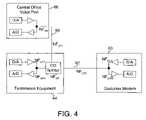
- FIG. 4is a communication system for noise floor calculations.
- Termination equipment 16may be part of a central office or digital loop carrier (CO) 10 or may be connected between customer premise equipment (CPE) 18 and the CO 10 as shown in FIG. 1 .
- the termination equipment 16terminates subscriber line 24 and provides a separate voice line 22 and data line 20 to PSTN switch 14 and data network 12 respectively at the CO 10 .
- subscriber line 24may carry various forms of communications such as DSL, voice calls, and dial-up modem calls.
- Subscriber line 24may be a twisted pair conductor, or POTS (plain old telephone system) line, which are common to the public switched telephone network. Subscriber line 24 may comprise other types of lines, such as coaxial cable.
- Termination equipment 16provides the necessary switching, interfaces, and signaling to enable said various forms of communications between the CO 10 and the CPE 18 .
- Examples of termination equipmentare DSLAMs (digital subscriber line access multiplexers), and channel banks.
- Another example of termination equipmentis a universal broadband server, which is a device operable to provide various types and levels of data and voice services to subscribers.
- Multiple customer premise equipment devices 18may be connected to a single termination equipment device 16 thereby providing voice and data services to multiple subscribers from a single device.
- the termination equipmentmay be located in a pedestal box, cross-connect cabinet, service area cross-connect, service area interface, or other box or cabinet located between a customer's home or business and the central office or digital loop carrier.
- the terms “pedestal box”, “cross-connect cabinet”, “service area cross-connect”, and “service area interface”are used interchangeably herein.
- the cross-connect cabinetis typically located less than 6000 feet from the subscriber. This location provides a short loop and access to a wide frequency spectrum.
- FIG. 2A faster modem apparatus for communicating with customer premise equipment, such as soft-modems, is shown in FIG. 2 .
- the faster modem apparatusinterfaces with an external processor or termination equipment, such as termination equipment 16 of FIG. 1 , via a microprocessor interface 54 .
- the apparatusincludes a subscriber line port 30 for connecting to a subscriber line, such as subscriber line 24 of FIG. 1 , and a central office port 32 for connecting to a voice line, such as voice line 22 of FIG. 1 .
- a low pass filter 34 coupled to the subscriber line port 30 and the central office port 32separates voice band signals from higher frequency data communication signals.
- the low pass filter 34is also referred to as an ADSL POTS splitter.
- the low pass filter 34is preferably an 8 kHz low pass filter and may be further compliant with the ANSI T1.413 specification.
- Isolation circuitry 36 connected to the subscriber line port 30provides isolation between a subscriber line and additional isolated circuitry 37 of the faster modem apparatus.
- isolation circuitrymay be used, such as a 1:1 transformer.
- the transformermay further have an insertion loss of less than 3 dB.
- the isolation circuitry 36is further connected to a switch 38 and the outputs of a line driver 40 .
- Both the switch 38 and the line driver 40are controlled via control lines 39 and 41 respectively.
- the control linesare coupled to the external processor or termination equipment to which the faster modem apparatus is connected.
- the switch 38 and line driver 40may alternatively be controlled via control lines 39 and 41 respectively by the additional isolated circuitry 37 of the faster modem apparatus, such as a digital signal processor 42 .
- the switch 38may be many types of switches such as a double-pole-double-throw relay.
- the line driver 40is a line driver with shut-down control such that the line driver is operable to be switched on and off via line driver control line 41 . Line drivers of this type are sold by many manufacturers and are commonly found in many types of telecommunication equipment.
- a hybrid unit 44is connected to switch 38 .
- the hybrid unitcomprises a first hybrid 46 and a second hybrid 48 .
- the first hybrid 46labeled “G Hybrid+Filter” in FIG. 2 , is a DSL hybrid and high pass filter, such as an ADSL hybrid, for filtering and separating two-line bi-directional DSL communication signals on lines 50 into receive only signals indicated by label “Rx” in FIG. 2 .
- the first hybrid 46may further be compliant with the ITU-T G.992.1 or ITU G.992.2 specifications.
- the high pass filter of the first hybrid 46is a high pass filter such as a 20 kHz high pass filter.
- the second hybrid 48is a voice band/analog modem band hybrid with low pass filter for separating two-line bi-directional voice or analog modem signals on lines 50 into receive only signals indicated by the label “Rx” in FIG. 2 .
- the second hybridmay be compliant with ITU-T V series specifications such as the ITU-T V.90 specification.
- the low pass filter of the second hybrid 48is a low pass filter such as a 20 kHz low pass filter.
- An analog front end 50is connected to the inputs of line driver 40 and to the outputs of hybrid unit 44 .
- the analog front end 50comprises codecs, or analog-to-digital and digital-to-analog converters.
- Analog receive signalsare received through subscriber port 30 via a subscriber line connected to subscriber port 30 , through isolation circuitry 36 , through switch 38 , and into hybrid unit 44 .
- the analog front endconverts analog receive signals (“Rx”) from the output of hybrid unit 44 into receive digital signals 52 for interfacing with the digital signal processor 42 and communicating with other equipment and processors, such as termination equipment, via microprocessor interface 54 .
- the analog front end 50further converts transmit digital signals 52 from the digital signal processor 42 into analog transmit signals (“Tx”) for input into line driver 40 and output onto a subscriber line connected to subscriber port 30 via isolation circuitry 36 .
- switch 38selects the appropriate first hybrid 46 or second hybrid 48 in hybrid unit 44 for effecting DSL communications or voice/analog modem communications, respectively.
- the digital signal processor 42is further in communication with a compression engine 56 for compressing and decompressing digital transmit and receive data according to an array of standards, such as the ITU-T V.42/V.42bis standard.
- digital signal processors 42may be used, such as those sold by GlobeSpan, Inc. Many modifications may be made to the faster modem apparatus. For example more than one digital signal processor 42 may be concurrently used, more than one type of compression engine 56 may be used, and additional hybrids may be used in the hybrid unit 44 . Further modifications include a switch between digital signal processor 42 and analog front end 50 for further switching digital data 52 . Additionally, digital signal processor 52 may comprise means for interfacing the digital signal processor 52 directly with high speed digital communication lines such as T 1 , T 3 , xDSL, ISDN, OCn, and the like. Further modifications will be evident to those of ordinary skill in the art.
- FIG. 3shows an alternative embodiment of the faster modem apparatus, for communicating with customer premise equipment, such as soft-modems.
- the faster modem apparatus of FIG. 3interfaces with an external processor or termination equipment, such as termination equipment 16 of FIG. 1 , via microprocessor interface 90 .
- the apparatusincludes a subscriber line port 70 for connecting to a subscriber line, such as subscriber line 24 of FIG. 1 , and for connecting to a voice line, such as voice line 22 of FIG. 1 .
- the apparatus in FIG. 3removes the low pass filter 34 of the apparatus of FIG. 2 .
- the filteris not necessary since the faster modem apparatus of FIG. 3 does not engage in DSL communications.
- the apparatus of FIG. 3is able to communicate according to dial-up modem and faster analog modem methods as described herein.
- Isolation circuitry 72 connected to the subscriber line port 70provides isolation between a subscriber line and additional isolated circuitry 74 of the faster modem apparatus.
- isolation circuitrymay be used, such as a 1:1 transformer.
- the transformermay further have an insertion loss of less than 3 dB.
- the isolation circuitry 74is further connected to the outputs of a line driver 80 and the inputs of hybrid 82 .
- the hybrid 82is a voice band/analog modem band hybrid with low pass filter labeled “V Hybrid+Filter” as described above in accordance with the apparatus of FIG. 2 .
- the line driver 80is also of the same type as described above and is controlled via a line driver control line 78 as described above.
- An analog front end 84is connected to the inputs of line driver 80 and to the outputs of hybrid unit 82 .
- a digital signal processor 88communicates digital transmit and receive signals 86 with the analog front end 84 .
- a compression engine 92is also connected to the digital signal processor 88 .
- the analog front end 84 , digital signal processor 88 , and compression engine 92are described above in accordance with FIG. 2 . Many modifications, such as those described above, can be made to the apparatus of FIG. 3 .
- the faster modem apparatus of FIGS. 2 and 3provides a means for terminating a subscriber line, and a means for carrying out multiple types of communication, such as voice, DSL, or analog modem, from a single device connected to the subscriber line.
- a means for carrying out multiple types of communicationsuch as voice, DSL, or analog modem
- the faster modem apparatus of FIGS. 2 and 3are configured to communicate using the appropriate protocols and signaling.
- the faster modem apparatus of FIG. 2also provides a means for conducting simultaneous data and voice communications on a single subscriber line.
- dial-up modemstake a phone line off-hook by applying a current load to the line.
- the PSTN voice switch14 of FIG. 1
- the PSTN voice switchshould be prevented from answering a call for faster modem service.
- the modem drivermay be modified to prevent the phone-line from being taken off-hook.
- the modificationmay, in part, include issuing a Hayes AT modem command “ATD” to the analog modem rather than the usual “ATDT” command.
- An alternative methodphysically disconnects the line from the central office when an “authorized” telephone number is dialed. This prevents the call from going through the PSTN by removing the customer from the PSTN.
- a preambleis dialed to the phone number and the voice or PSTN switch is signaled by the presence of the preamble not to answer the call. For example, by adding the numbers “#55” to the beginning of the phone number, the voice switch ignores the call by at least in part removing the dial tone and not recognizing further DTMF signals.
- the termination equipmentsuch as the faster modem apparatus or the faster modem apparatus in conjunction with additional termination equipment like a universal broadband server, answers the dial-up modem call, such as a V.90 call.
- soft-modemsdigitize, or sample, signals in the voice band up to around 4 kHz.
- Soft-modemsare designed for voice band communications and are therefore not capable of digitizing or sampling signals in the ADSL band, or any other DSL technology band.
- the term “codec operating range”is defined broadly to mean the range of frequencies at which a codec can operate to sample, or digitize, signals. For example, if a codec has an operating range of 44 kHz, and is operating at 44 kHz, then the codec can effectively code and decode signals of up to 22 kHz in frequency. Or, if a codec has an operating range of 44 kHz but is only operating at 8 kHz, then the codec can effectively code and decode signals of up to 4 kHz in frequency.
- codecs in most soft modemsoperate at only up to 8 kHz, their operating range extends far beyond 8 kHz. Specifically, most soft-modem codecs can operate at up to 12 kHz, and often up to 44 kHz. Therefore, most soft-modem codecs have a bandwidth, or can sample signals, from around 6 kHz to 22 kHz, much greater than the 4 kHz currently used.
- soft-modemsWhile the transmission level of soft-modems is limited by PSTN requirements to ⁇ 9 dBm, most soft-modems are capable of transmitting and receiving signals at a much higher level, for example at 0 dBm. As with most of the operational characteristics of soft-modems, the digitizing frequency range and transmitting and receiving levels are controlled by the driver software running on the host computer of the soft-modem.
- a faster analog modem communication methodutilizes the unused codec operating range of the soft-modem above the 4 kHz voice band, as well as the soft-modem's ability to transmit and receive signals at a signal level above ⁇ 9 dBm.
- the faster analog modem communication methodmay be implemented on both the customer premise equipment side, and at the termination equipment side, such as in the faster modem apparatus described above, to effect a bi-directional increase in communication speed.
- the faster analog modem in communication with a remote communication deviceutilizes an unused portion of the analog modem codec operating range to code and decode data signals. This unused portion may range from around 8 kHz to around 44 kHz, therefore allowing the sampling of signals above 4 kHz in frequency.
- upstream coded analog signals(signals traveling from the customer premise equipment to the remote communication device) are transmitted at a level of greater than ⁇ 9 dBm between the remote communication device and faster analog modem at the customer premise.
- Downstream coded analog signals(signals traveling from the remote communication device to the customer premise equipment) are received at a level of greater than ⁇ 9 dBm between the remote communication device and the faster analog modem at the customer premise.
- the coded analog signalsmay be transmitted at 0 dBm or even up to 5 dBm to overdrive the loss in the loop, typically around 4 dB, thereby achieving a signal level of 0 dBm at the receiver of the remote communication device or customer premise equipment.
- Coded analog signalsmay be received at 0 dBm meaning that the transmitting device is transmitting at a level of at least 0 dBm, such as around 5 dBm.
- a value for the noise floor necessary for making the calculations of Table 1is calculated by referring to FIG. 4 .
- a customer modem 60such as a soft-modem is connected by a subscriber line 62 to termination equipment 64 such as the faster modem apparatus of FIG. 2 .
- the termination equipment 64is further connected to a central office voice port via a central office voice line 68 .
- the following labels used for the noise floor calculationare indicated below:
- NF VFRUBS Port Receiver Noise Factor
- NF LP2Pedestal to customer Noise Factor
- NF XTCross-Talk Noise Factor (Cross-talk represents the noise added due to cross-talk between multiple loops connected, for example, between termination equipment 64 and multiple customer modems 60 .)
- NF DNF TH +NF VP +NF LP1 +NF VFT +NF SP +NF LP2 +NF CPR +NF XT
- NF UNF TH +NF VP +NF LP1 +NF VFR +NF SP +NF LP2 +NF CPT +NF XT .
- noise factor of the transmission pathswill be limited by the transmitters, receivers, and cross-talk.
- a noise factor of ⁇ 40 dBm to ⁇ 80 dBmis typical in a system such as shown in FIG. 4 .
- Handshaking, synchronization techniques, and standards currently employed in soft-modemsare used in the faster soft-modem.
- handshaking between the termination equipment and CPE modem employing the faster modem methodcomprise the well understood ITU-T V.8/V.8bis handshake protocol.
- ITU-T V.14 synchronization techniques, and ITU-T V.42/V.42bis compression techniquesare used.
- ITU-T V.34 modulation techniquesare also employed.
- PAM, QAM, CAP or DMT modulation techniquescan be substituted for or combined with the V.34 modulation techniques.
Landscapes
- Engineering & Computer Science (AREA)
- Computer Networks & Wireless Communication (AREA)
- Signal Processing (AREA)
- Telephonic Communication Services (AREA)
Abstract
Description
| TABLE I | ||
| Bandwidth | Capacity (C) | |
| (BW) | SNR | (kbps) |
| 6 | 32 | 64 |
| 41 | 82 | |
| 50 | 100 | |
| 60 | 120 | |
| 70 | 140 | |
| 80 | 160 | |
| 10 | 32 | 106 |
| 41 | 136 | |
| 50 | 166 | |
| 60 | 200 | |
| 70 | 232 | |
| 80 | 265 | |
| 16 | 32 | 170 |
| 41 | 217 | |
| 50 | 265 | |
| 60 | 320 | |
| 70 | 372 | |
| 80 | 425 | |
| 20 | 32 | 212 |
| 41 | 272 | |
| 50 | 332 | |
| 60 | 400 | |
| 70 | 465 | |
| 80 | 531 | |
NFD=NFTH+NFVP+NFLP1+NFVFT+NFSP+NFLP2+NFCPR+NFXT,
and the overall upstream noise factor NFUis:
NFU=NFTH+NFVP+NFLP1+NFVFR+NFSP+NFLP2+NFCPT+NFXT.
Claims (13)
Priority Applications (3)
| Application Number | Priority Date | Filing Date | Title |
|---|---|---|---|
| US10/194,375US7233649B2 (en) | 2002-07-12 | 2002-07-12 | Faster modem method and apparatus |
| AU2003253829AAU2003253829A1 (en) | 2002-07-12 | 2003-07-03 | Faster modem method and apparatus |
| PCT/US2003/021395WO2004008653A1 (en) | 2002-07-12 | 2003-07-03 | Faster modem method and apparatus |
Applications Claiming Priority (1)
| Application Number | Priority Date | Filing Date | Title |
|---|---|---|---|
| US10/194,375US7233649B2 (en) | 2002-07-12 | 2002-07-12 | Faster modem method and apparatus |
Publications (2)
| Publication Number | Publication Date |
|---|---|
| US20040008761A1 US20040008761A1 (en) | 2004-01-15 |
| US7233649B2true US7233649B2 (en) | 2007-06-19 |
Family
ID=30114726
Family Applications (1)
| Application Number | Title | Priority Date | Filing Date |
|---|---|---|---|
| US10/194,375Expired - LifetimeUS7233649B2 (en) | 2002-07-12 | 2002-07-12 | Faster modem method and apparatus |
Country Status (3)
| Country | Link |
|---|---|
| US (1) | US7233649B2 (en) |
| AU (1) | AU2003253829A1 (en) |
| WO (1) | WO2004008653A1 (en) |
Cited By (3)
| Publication number | Priority date | Publication date | Assignee | Title |
|---|---|---|---|---|
| US20050111365A1 (en)* | 2003-11-07 | 2005-05-26 | Reinhard Bloeckl | Hybrid DSL system for transmission of hybrid DSL data via a subscriber access line in order to increase the overall data transmission rate of both transceivers |
| US20090300702A1 (en)* | 2005-03-01 | 2009-12-03 | Keith Johnson | Early Warning Fault Identification and Isolation System for a Two-Way Cable Network |
| US8161517B2 (en) | 2005-08-31 | 2012-04-17 | Time Warner Cable, Inc. | System and method for assigning and verifying CPE service calls in a cable network |
Families Citing this family (32)
| Publication number | Priority date | Publication date | Assignee | Title |
|---|---|---|---|---|
| US6001067A (en)* | 1997-03-04 | 1999-12-14 | Shults; Mark C. | Device and method for determining analyte levels |
| US6702857B2 (en)* | 2001-07-27 | 2004-03-09 | Dexcom, Inc. | Membrane for use with implantable devices |
| US10142023B2 (en) | 2003-01-31 | 2018-11-27 | Centurylink Intellectual Property Llc | Antenna system and methods for wireless optical network termination |
| US8490129B2 (en) | 2003-01-31 | 2013-07-16 | Qwest Communications International Inc. | Methods, systems and apparatus for selectively distributing urgent public information |
| US7793003B2 (en)* | 2003-01-31 | 2010-09-07 | Qwest Communications International Inc | Systems and methods for integrating microservers with a network interface device |
| US8050281B2 (en)* | 2003-01-31 | 2011-11-01 | Qwest Communications International Inc. | Alert gateway, systems and methods |
| US7134999B2 (en)* | 2003-04-04 | 2006-11-14 | Dexcom, Inc. | Optimized sensor geometry for an implantable glucose sensor |
| US7875293B2 (en)* | 2003-05-21 | 2011-01-25 | Dexcom, Inc. | Biointerface membranes incorporating bioactive agents |
| WO2007120442A2 (en)* | 2003-07-25 | 2007-10-25 | Dexcom, Inc. | Dual electrode system for a continuous analyte sensor |
| US7920906B2 (en) | 2005-03-10 | 2011-04-05 | Dexcom, Inc. | System and methods for processing analyte sensor data for sensor calibration |
| US20050090607A1 (en)* | 2003-10-28 | 2005-04-28 | Dexcom, Inc. | Silicone composition for biocompatible membrane |
| US9247900B2 (en) | 2004-07-13 | 2016-02-02 | Dexcom, Inc. | Analyte sensor |
| US8423114B2 (en) | 2006-10-04 | 2013-04-16 | Dexcom, Inc. | Dual electrode system for a continuous analyte sensor |
| ATE480761T1 (en) | 2003-12-05 | 2010-09-15 | Dexcom Inc | CALIBRATION METHODS FOR A CONTINUOUSLY WORKING ANALYTICAL SENSOR |
| US11633133B2 (en) | 2003-12-05 | 2023-04-25 | Dexcom, Inc. | Dual electrode system for a continuous analyte sensor |
| US7364592B2 (en)* | 2004-02-12 | 2008-04-29 | Dexcom, Inc. | Biointerface membrane with macro-and micro-architecture |
| US20050245799A1 (en)* | 2004-05-03 | 2005-11-03 | Dexcom, Inc. | Implantable analyte sensor |
| KR100621571B1 (en)* | 2004-06-25 | 2006-09-14 | 삼성전자주식회사 | Network repeater and relay method |
| US20060016700A1 (en)* | 2004-07-13 | 2006-01-26 | Dexcom, Inc. | Transcutaneous analyte sensor |
| US7654956B2 (en) | 2004-07-13 | 2010-02-02 | Dexcom, Inc. | Transcutaneous analyte sensor |
| US20070045902A1 (en)* | 2004-07-13 | 2007-03-01 | Brauker James H | Analyte sensor |
| FR2876519A1 (en)* | 2004-10-11 | 2006-04-14 | France Telecom | DEVICE FOR CONNECTING EQUIPMENT xDSL |
| US20060218612A1 (en)* | 2005-03-01 | 2006-09-28 | Keith Johnson | Fault detection and isolation system for an HFC cable network and method therefor |
| US8060174B2 (en)* | 2005-04-15 | 2011-11-15 | Dexcom, Inc. | Analyte sensing biointerface |
| US7706252B2 (en)* | 2005-07-21 | 2010-04-27 | Time Warner Cable, Inc. | System and method for locating faults in a hybrid fiber coax (HFC) cable network |
| US7509669B2 (en)* | 2005-08-31 | 2009-03-24 | Time Warner Cable, Inc. | VOD transaction error correlator |
| US7810127B2 (en)* | 2005-08-31 | 2010-10-05 | Time Warner Cable, Inc. | System and method for evaluating the operational status of a STB in a cable network |
| US7506354B2 (en) | 2005-08-31 | 2009-03-17 | Time Warner Cable, Inc. | VOD transaction error correlator |
| US7599300B2 (en)* | 2005-08-31 | 2009-10-06 | Time Warner Cable, Inc. | Cable modem analysis system and method therefor for an HFC cable network |
| FR2913165A1 (en)* | 2007-02-26 | 2008-08-29 | France Telecom | Low frequency signals reinjecting device for wired local loop framework, has low pass filter connected to transmission line, and protection circuit connected to filter and foreign exchange subscriber port of modem |
| US9497800B2 (en) | 2012-07-05 | 2016-11-15 | Centurylink Intellectual Property Llc | Multi-service provider wireless access point |
| US9392641B2 (en) | 2012-07-05 | 2016-07-12 | Centurylink Intellectual Property Llc | Multi-service provider wireless access point |
Citations (22)
| Publication number | Priority date | Publication date | Assignee | Title |
|---|---|---|---|---|
| US4393492A (en) | 1981-02-17 | 1983-07-12 | Reliance Electric Co. | Digital subscriber carrier system including drop terminals and bypass and loopback means and alarm indication means |
| US4730311A (en) | 1985-03-12 | 1988-03-08 | Pacific Bell | Remote multiplexer for digital telephone system |
| USH1175H (en) | 1988-05-04 | 1993-04-06 | The United States Of America As Represented By The Secretary Of The Navy | Dynamic channel selection system |
| US5260937A (en) | 1990-10-29 | 1993-11-09 | Dsc Communications Corporation | Power conserving technique for a communications terminal time slot interchanger |
| US5390239A (en) | 1994-03-17 | 1995-02-14 | Morris; Gregory A. | Method for increasing digital data throughput over telephone lines |
| WO1999020033A1 (en) | 1997-10-15 | 1999-04-22 | Cisco Technologies, Inc. | Data communication using a modifiable number of xdsl modems |
| US5898761A (en) | 1996-03-29 | 1999-04-27 | Cisco Technology, Inc. | Communication server apparatus using digital signal switching and method |
| US5905778A (en) | 1998-02-06 | 1999-05-18 | Shires; Mark Richard | Notification apparatus for outbound data communication system |
| US5923671A (en) | 1996-07-22 | 1999-07-13 | At&T Corp | Coupling multiple low data rate lines to effect high data rate communication |
| US6005873A (en) | 1997-08-27 | 1999-12-21 | Eci Telecom Ltd. | Apparatus and method for concurrent voice and data transmission |
| US6009106A (en) | 1997-11-19 | 1999-12-28 | Digi International, Inc. | Dynamic bandwidth allocation within a communications channel |
| US6014431A (en) | 1996-03-29 | 2000-01-11 | Cisco Technology, Inc. | Communication server apparatus having four-wire switching interface and method |
| US6061392A (en) | 1996-12-17 | 2000-05-09 | Paradyne Corporation | Apparatus and method for communicating voice and data between a customer premises and a central office |
| US6084874A (en) | 1998-06-30 | 2000-07-04 | Storage Technology Corporation | Temporary data transfer connections |
| US6160843A (en) | 1996-03-29 | 2000-12-12 | Cisco Technology, Inc. | Communication server apparatus providing XDSL services and method |
| US6160808A (en) | 1997-12-18 | 2000-12-12 | 3Com Corporation | Technique for transmitting incoming multi-link point-to-point (PPP) packet traffic over multiple outgoing links in a multi-link bundle |
| US6169788B1 (en) | 1996-03-29 | 2001-01-02 | Cisco Technology, Inc. | Communication server apparatus having distributed switching and method |
| US6198749B1 (en) | 1997-04-03 | 2001-03-06 | Nortel Networks Limited | System for inverse multiplexing analog channels |
| US6324212B1 (en) | 1999-02-12 | 2001-11-27 | Siemens Information And Communication Networks, Inc. | Apparatus using low spectrum selectively for providing both ADSL and POTS service |
| US6349123B1 (en) | 1997-08-30 | 2002-02-19 | Samsung Electronics Co., Ltd. | Asymmetric data transmission apparatus using asymmetric digital subscriber lines, and subscriber line connection method therefor |
| US6373852B1 (en) | 1996-07-15 | 2002-04-16 | At&T Corp. | Coupling multiple low data rate lines to effect high data rate communication |
| US6895040B2 (en)* | 2001-05-01 | 2005-05-17 | Silicon Laboratories, Inc. | Architecture for a digital subscriber line analog front end |
- 2002
- 2002-07-12USUS10/194,375patent/US7233649B2/ennot_activeExpired - Lifetime
- 2003
- 2003-07-03AUAU2003253829Apatent/AU2003253829A1/ennot_activeAbandoned
- 2003-07-03WOPCT/US2003/021395patent/WO2004008653A1/ennot_activeApplication Discontinuation
Patent Citations (22)
| Publication number | Priority date | Publication date | Assignee | Title |
|---|---|---|---|---|
| US4393492A (en) | 1981-02-17 | 1983-07-12 | Reliance Electric Co. | Digital subscriber carrier system including drop terminals and bypass and loopback means and alarm indication means |
| US4730311A (en) | 1985-03-12 | 1988-03-08 | Pacific Bell | Remote multiplexer for digital telephone system |
| USH1175H (en) | 1988-05-04 | 1993-04-06 | The United States Of America As Represented By The Secretary Of The Navy | Dynamic channel selection system |
| US5260937A (en) | 1990-10-29 | 1993-11-09 | Dsc Communications Corporation | Power conserving technique for a communications terminal time slot interchanger |
| US5390239A (en) | 1994-03-17 | 1995-02-14 | Morris; Gregory A. | Method for increasing digital data throughput over telephone lines |
| US6160843A (en) | 1996-03-29 | 2000-12-12 | Cisco Technology, Inc. | Communication server apparatus providing XDSL services and method |
| US5898761A (en) | 1996-03-29 | 1999-04-27 | Cisco Technology, Inc. | Communication server apparatus using digital signal switching and method |
| US6169788B1 (en) | 1996-03-29 | 2001-01-02 | Cisco Technology, Inc. | Communication server apparatus having distributed switching and method |
| US6014431A (en) | 1996-03-29 | 2000-01-11 | Cisco Technology, Inc. | Communication server apparatus having four-wire switching interface and method |
| US6373852B1 (en) | 1996-07-15 | 2002-04-16 | At&T Corp. | Coupling multiple low data rate lines to effect high data rate communication |
| US5923671A (en) | 1996-07-22 | 1999-07-13 | At&T Corp | Coupling multiple low data rate lines to effect high data rate communication |
| US6061392A (en) | 1996-12-17 | 2000-05-09 | Paradyne Corporation | Apparatus and method for communicating voice and data between a customer premises and a central office |
| US6198749B1 (en) | 1997-04-03 | 2001-03-06 | Nortel Networks Limited | System for inverse multiplexing analog channels |
| US6005873A (en) | 1997-08-27 | 1999-12-21 | Eci Telecom Ltd. | Apparatus and method for concurrent voice and data transmission |
| US6349123B1 (en) | 1997-08-30 | 2002-02-19 | Samsung Electronics Co., Ltd. | Asymmetric data transmission apparatus using asymmetric digital subscriber lines, and subscriber line connection method therefor |
| WO1999020033A1 (en) | 1997-10-15 | 1999-04-22 | Cisco Technologies, Inc. | Data communication using a modifiable number of xdsl modems |
| US6009106A (en) | 1997-11-19 | 1999-12-28 | Digi International, Inc. | Dynamic bandwidth allocation within a communications channel |
| US6160808A (en) | 1997-12-18 | 2000-12-12 | 3Com Corporation | Technique for transmitting incoming multi-link point-to-point (PPP) packet traffic over multiple outgoing links in a multi-link bundle |
| US5905778A (en) | 1998-02-06 | 1999-05-18 | Shires; Mark Richard | Notification apparatus for outbound data communication system |
| US6084874A (en) | 1998-06-30 | 2000-07-04 | Storage Technology Corporation | Temporary data transfer connections |
| US6324212B1 (en) | 1999-02-12 | 2001-11-27 | Siemens Information And Communication Networks, Inc. | Apparatus using low spectrum selectively for providing both ADSL and POTS service |
| US6895040B2 (en)* | 2001-05-01 | 2005-05-17 | Silicon Laboratories, Inc. | Architecture for a digital subscriber line analog front end |
Non-Patent Citations (7)
| Title |
|---|
| "Connection Optimized Link Technology," White paper, Ramp Networks, 6 pages, (1998). |
| "Copper Edge 200 RT DSL Concentrator," 4 pages, Aug. 2001. |
| "Dualing Modems Reach 112K," Wired News, 3 pages, Feb. 3, 2000. |
| "Multi-Tenant Unit Profitability Analysis," 10 pages, Dec. 2000. |
| "Powerful Internet and Remote Access Platform," WebRamp 361i, 2 pages, Mar. 2000. |
| "SupraSonic Dual Modem: Twice is Nice," PCWorld.com, 3 pages, Jul. 27, 1998. |
| "X-Cel & GDSL System V.90 RIs@ Analog Modem Support," GoDigital Networks-Technical Note, 7 pages, Jan. 23, 2001. |
Cited By (5)
| Publication number | Priority date | Publication date | Assignee | Title |
|---|---|---|---|---|
| US20050111365A1 (en)* | 2003-11-07 | 2005-05-26 | Reinhard Bloeckl | Hybrid DSL system for transmission of hybrid DSL data via a subscriber access line in order to increase the overall data transmission rate of both transceivers |
| US7440402B2 (en)* | 2003-11-07 | 2008-10-21 | Infineon Technologies Ag | Hybrid DSL system for transmission of hybrid DSL data via a subscriber access line in order to increase the overall data transmission rate of both transceivers |
| US20090300702A1 (en)* | 2005-03-01 | 2009-12-03 | Keith Johnson | Early Warning Fault Identification and Isolation System for a Two-Way Cable Network |
| US7930725B2 (en) | 2005-03-01 | 2011-04-19 | Time Warner Cable, Inc. | Early warning fault identification and isolation system for a two-way cable network |
| US8161517B2 (en) | 2005-08-31 | 2012-04-17 | Time Warner Cable, Inc. | System and method for assigning and verifying CPE service calls in a cable network |
Also Published As
| Publication number | Publication date |
|---|---|
| AU2003253829A1 (en) | 2004-02-02 |
| WO2004008653A1 (en) | 2004-01-22 |
| US20040008761A1 (en) | 2004-01-15 |
Similar Documents
| Publication | Publication Date | Title |
|---|---|---|
| US7233649B2 (en) | Faster modem method and apparatus | |
| US6522730B1 (en) | DSL communication system with improved bandwidth | |
| US5815505A (en) | Combined analog and digital communications device | |
| US5898761A (en) | Communication server apparatus using digital signal switching and method | |
| US5852655A (en) | Communication server apparatus having distributed switching and method | |
| EP1155564B1 (en) | Splitter-less digital subscriber loop modem | |
| US20110019725A1 (en) | Dsl method having variable upload/download bit rate and application-specific dynamic profile switching | |
| US6693916B1 (en) | Method and system for combining symmetric DSL signals and voice signals | |
| US20020101852A1 (en) | POTS/xDSL services line sharing for multiple subscribers | |
| WO2001047234A1 (en) | Home networking using existing dsl equipment | |
| US20060153169A1 (en) | Customer premises network with PSTN and packet telephony functions | |
| US6456650B1 (en) | Splitterless modem using harmonics reduction | |
| US6647024B1 (en) | System and method for an all digital communication system with a life line | |
| US7564797B2 (en) | Method and system for conveying multiple calls on a single telephone line | |
| US6922415B1 (en) | Apparatus and method for a non-symmetrical half-duplex DSL modem | |
| WO1999018712A1 (en) | COMBINED xDSL AND PSTN MODEMS IN A SINGLE PLATFORM | |
| US7564868B2 (en) | Configuration DSL transceiver | |
| KR100345191B1 (en) | ACTIVATION OF MULTIPLE xDSL MODEMS WITH HALF DUPLEX AND FULL DUPLEX PROCEDURES | |
| US7362856B2 (en) | Subscriber line interface circuitry transceiver | |
| US7218729B2 (en) | Subscriber line interface circuitry with current drivers for downstream voice and data signals | |
| US7362855B2 (en) | Subscriber line interface circuitry transceiver | |
| US7372900B2 (en) | Method and system for selecting an optimal asymmetric digital subscriber line mode | |
| US7362857B2 (en) | Subscriber line interface circuitry transceiver | |
| US7130335B1 (en) | Multi-line ADSL modem | |
| KR100359476B1 (en) | Internal ADSL modem which support voice over Internet Protocol with legacy telephone |
Legal Events
| Date | Code | Title | Description |
|---|---|---|---|
| AS | Assignment | Owner name:PEDESTAL NETWORKS INCORPORATED, CALIFORNIA Free format text:MORTGAGE;ASSIGNORS:KELLIHER, TIMOTHY L.;FARMWALD, P. MICHAEL;REEL/FRAME:013104/0767 Effective date:20020712 | |
| AS | Assignment | Owner name:VENTURE LENDING & LEASING III, INC., CALIFORNIA Free format text:SECURITY INTEREST;ASSIGNOR:PEDESTAL NETWORKS, INC.;REEL/FRAME:014026/0038 Effective date:20030327 | |
| AS | Assignment | Owner name:UTSTARCOM, INC., CALIFORNIA Free format text:ASSIGNMENT OF ASSIGNORS INTEREST;ASSIGNOR:PEDESTAL NETWORKS, INC.;REEL/FRAME:016164/0961 Effective date:20050617 | |
| FEPP | Fee payment procedure | Free format text:PAYOR NUMBER ASSIGNED (ORIGINAL EVENT CODE: ASPN); ENTITY STATUS OF PATENT OWNER: LARGE ENTITY | |
| STCF | Information on status: patent grant | Free format text:PATENTED CASE | |
| AS | Assignment | Owner name:PEDESTAL NETWORKS, INC., CALIFORNIA Free format text:RELEASE BY SECURED PARTY;ASSIGNOR:VENTURE LENDING & LEASING III;REEL/FRAME:021085/0988 Effective date:20080613 | |
| AS | Assignment | Owner name:TASOM MOBILE TRANSFER CO. LLC, DELAWARE Free format text:ASSIGNMENT OF ASSIGNORS INTEREST;ASSIGNOR:UTSTARCOM, INC.;REEL/FRAME:021316/0733 Effective date:20080613 | |
| FEPP | Fee payment procedure | Free format text:PAYER NUMBER DE-ASSIGNED (ORIGINAL EVENT CODE: RMPN); ENTITY STATUS OF PATENT OWNER: LARGE ENTITY Free format text:PAYOR NUMBER ASSIGNED (ORIGINAL EVENT CODE: ASPN); ENTITY STATUS OF PATENT OWNER: LARGE ENTITY | |
| FPAY | Fee payment | Year of fee payment:4 | |
| FEPP | Fee payment procedure | Free format text:PAYOR NUMBER ASSIGNED (ORIGINAL EVENT CODE: ASPN); ENTITY STATUS OF PATENT OWNER: LARGE ENTITY Free format text:PAYER NUMBER DE-ASSIGNED (ORIGINAL EVENT CODE: RMPN); ENTITY STATUS OF PATENT OWNER: LARGE ENTITY | |
| FPAY | Fee payment | Year of fee payment:8 | |
| AS | Assignment | Owner name:F. POSZAT HU, L.L.C., DELAWARE Free format text:MERGER;ASSIGNOR:TASOM MOBILE TRANSFER CO. LLC;REEL/FRAME:037547/0133 Effective date:20150812 | |
| MAFP | Maintenance fee payment | Free format text:PAYMENT OF MAINTENANCE FEE, 12TH YEAR, LARGE ENTITY (ORIGINAL EVENT CODE: M1553); ENTITY STATUS OF PATENT OWNER: LARGE ENTITY Year of fee payment:12 |