US7232008B2 - Active anti-tip wheels for power wheelchair - Google Patents
Active anti-tip wheels for power wheelchairDownload PDFInfo
- Publication number
- US7232008B2 US7232008B2US10/943,713US94371304AUS7232008B2US 7232008 B2US7232008 B2US 7232008B2US 94371304 AUS94371304 AUS 94371304AUS 7232008 B2US7232008 B2US 7232008B2
- Authority
- US
- United States
- Prior art keywords
- tip
- assembly
- mounting
- drive
- wheel
- Prior art date
- Legal status (The legal status is an assumption and is not a legal conclusion. Google has not performed a legal analysis and makes no representation as to the accuracy of the status listed.)
- Expired - Lifetime, expires
Links
Images


Classifications
- A—HUMAN NECESSITIES
- A61—MEDICAL OR VETERINARY SCIENCE; HYGIENE
- A61G—TRANSPORT, PERSONAL CONVEYANCES, OR ACCOMMODATION SPECIALLY ADAPTED FOR PATIENTS OR DISABLED PERSONS; OPERATING TABLES OR CHAIRS; CHAIRS FOR DENTISTRY; FUNERAL DEVICES
- A61G5/00—Chairs or personal conveyances specially adapted for patients or disabled persons, e.g. wheelchairs
- A61G5/04—Chairs or personal conveyances specially adapted for patients or disabled persons, e.g. wheelchairs motor-driven
- A61G5/041—Chairs or personal conveyances specially adapted for patients or disabled persons, e.g. wheelchairs motor-driven having a specific drive-type
- A61G5/043—Mid wheel drive
- A—HUMAN NECESSITIES
- A61—MEDICAL OR VETERINARY SCIENCE; HYGIENE
- A61G—TRANSPORT, PERSONAL CONVEYANCES, OR ACCOMMODATION SPECIALLY ADAPTED FOR PATIENTS OR DISABLED PERSONS; OPERATING TABLES OR CHAIRS; CHAIRS FOR DENTISTRY; FUNERAL DEVICES
- A61G5/00—Chairs or personal conveyances specially adapted for patients or disabled persons, e.g. wheelchairs
- A61G5/06—Chairs or personal conveyances specially adapted for patients or disabled persons, e.g. wheelchairs with obstacle mounting facilities, e.g. for climbing stairs, kerbs or steps
- A—HUMAN NECESSITIES
- A61—MEDICAL OR VETERINARY SCIENCE; HYGIENE
- A61G—TRANSPORT, PERSONAL CONVEYANCES, OR ACCOMMODATION SPECIALLY ADAPTED FOR PATIENTS OR DISABLED PERSONS; OPERATING TABLES OR CHAIRS; CHAIRS FOR DENTISTRY; FUNERAL DEVICES
- A61G5/00—Chairs or personal conveyances specially adapted for patients or disabled persons, e.g. wheelchairs
- A61G5/10—Parts, details or accessories
- A61G5/1078—Parts, details or accessories with shock absorbers or other suspension arrangements between wheels and frame
- A—HUMAN NECESSITIES
- A61—MEDICAL OR VETERINARY SCIENCE; HYGIENE
- A61G—TRANSPORT, PERSONAL CONVEYANCES, OR ACCOMMODATION SPECIALLY ADAPTED FOR PATIENTS OR DISABLED PERSONS; OPERATING TABLES OR CHAIRS; CHAIRS FOR DENTISTRY; FUNERAL DEVICES
- A61G5/00—Chairs or personal conveyances specially adapted for patients or disabled persons, e.g. wheelchairs
- A61G5/10—Parts, details or accessories
- A61G5/1089—Anti-tip devices
- Y—GENERAL TAGGING OF NEW TECHNOLOGICAL DEVELOPMENTS; GENERAL TAGGING OF CROSS-SECTIONAL TECHNOLOGIES SPANNING OVER SEVERAL SECTIONS OF THE IPC; TECHNICAL SUBJECTS COVERED BY FORMER USPC CROSS-REFERENCE ART COLLECTIONS [XRACs] AND DIGESTS
- Y10—TECHNICAL SUBJECTS COVERED BY FORMER USPC
- Y10S—TECHNICAL SUBJECTS COVERED BY FORMER USPC CROSS-REFERENCE ART COLLECTIONS [XRACs] AND DIGESTS
- Y10S180/00—Motor vehicles
- Y10S180/907—Motorized wheelchairs
Definitions
- the present inventionrelates to powered vehicles, such as power wheelchairs, and more particularly to a new and useful power vehicle having an anti-tip system for greater maneuverability while furthermore enhancing pitch stability.
- Mid-wheel powered wheelchairsare designed to position the drive wheels, i.e., the rotational axes thereof, slightly forward of the occupant's Center Of Gravity (COG) to provide enhanced mobility and maneuverability.
- COGCenter Of Gravity
- Anti-tip systemsprovide enhanced stability of the wheelchair about its pitch axis and, in some of the more sophisticated anti-tip designs, improve the obstacle or curb-climbing ability of the wheelchair.
- Such mid-wheel powered wheelchairs and/or powered wheelchairs having anti-tip systemsare disclosed in Schaffner et al. U.S. Pat. Nos. 5,944,131 & 6,129,165, both issued and assigned to Pride Mobility Products Corporation located in Singer, Pa.
- the Schaffner '131 patentdiscloses a mid-wheel drive wheelchair having a passive anti-tip system.
- a brief examination thereofreveals that two separate and distinct suspension struts are employed for mounting (i) the drive wheel/drive train assembly to the main structural frame of the wheelchair, and (ii) an anti-tip wheel to a forward portion of the main structural frame.
- passive anti-tip systemstypically necessitate the use of two independent spring-strut assemblies thus increasing mechanical complexity, maintenance requirements, cost (i.e., the cost of two spring-strut assemblies), and weight.
- the Schaffner '165 patentdiscloses a mid-wheel drive powered wheelchair having an anti-tip system which is “active” in contrast to the passive system discussed previously and disclosed in the '131 patent.
- anti-tip systemsare responsive to accelerations or decelerations of the wheelchair to actively vary the position of the anti-tip wheels, thereby improving the wheelchair's ability to climb curbs or overcome obstacles.
- the active anti-tip systemmechanically couples the suspension system of the anti-tip wheel to the drive-train assembly such that the anti-tip wheels displace upwardly or downwardly as a function of the magnitude of torque applied to the drive train assembly.
- the systemsare mechanically coupled by a longitudinal suspension arm pivotally mounted to the main structural frame.
- a drive-train assemblyTo one end of the suspension arm is mounted a drive-train assembly, and, to the other end, an anti-tip wheel.
- the suspension armis pivotally mounted at a single point, between the drive-train assembly and the anti-tip wheel, and spring-biased to a neutral position by a pair of spring-strut assemblies, each one of the pair being disposed on an opposite side of the pivot mount.
- the downward motion of the anti-tip wheelassists to stabilize the wheelchair wheels when traversing downwardly sloping terrain or a negative decline.
- the anti-tip system“actively” responds to a change in applied torque to vary the position of the anti-tip wheel.
- the active anti-tip system disclosed in the Schaffner patent '165offers significant advances by comparison to prior art passive systems, it too has certain drawbacks and limitations.
- the active anti-tip system of Schaffneralso requires two spring-strut assemblies to bias the position of each anti-tip wheel. While only requiring a single pivot connection, for mounting or suspending the anti-tip system, the dual spring-strut arrangement is mechanically complex, costly, requires periodic maintenance and adds weight.
- Yet another disadvantage of such active anti-tip systemrelates to design limitations caused by the single pivot connection and, consequently, performance compromises.
- the one piece construction of the suspension armnecessarily requires that both the drive-train assembly and the respective anti-tip wheel must necessarily enscribe the same angle, i.e., the angles are identical.
- the angleare identical.
- the horizontal path taken by the anti-tip wheelswill vary in accordance with the arm radius.
- the anti-tip wheelstraverse a more arcuate path, i.e., rather than a substantially linear path. This variation can significantly impact the curb-climbing ability of the anti-tip system. More specifically, it will be appreciated that when a curb or obstacle impacts the anti-tip wheel at or near a point which is in-line with the wheel's rotational axis, the anti-tip wheel will have a tendency to move upward or downward depending upon the vertical location of the pivot axis of the suspension arm.
- an anti-tip wheelwill have a tendency to move downwardly under the above described loading conditions. This downward travel is, of course, contrary to a desired upward motion for climbing curbs or other obstacles.
- At least one pair of anti-tip wheelsis typically castored, i.e., for pivoting/rotation about a vertical axis.
- castored wheelsoccupy valuable space aboard powered wheelchairs, e.g., interfere with footrest assemblies or an occupants feet/legs, sometimes one of the anti-tip wheel pairs to enable unrestricted yaw control/motion of the wheelchair 2 . Consequently, there may be a lag in pitch stabilization response.
- An anti-tip systemfor stabilizing a vehicle, such as a powered wheelchair, about a pitch axis and relative to a ground plane.
- the anti-tip systemincludes at least one anti-tip wheel disposed on a side of the wheelchair pitch axis, an assembly for mounting the anti-tip wheel to the main structural frame, and a suspension assembly.
- the mounting assemblyis configured to cause the anti-tip wheel to traverse linearly in response to an acceleration of the wheelchair.
- the suspension assemblyis disposed in combination with the mounting assembly and biases the anti-tip wheels to a predetermined operating position.
- the anti-tip wheelsare castored, i.e., both forward and aft stabilizing anti-tip wheels, and the predetermined operating position corresponds to the anti-tip wheels contacting the ground plane during normal wheelchair operation.
- a compliant mounting assemblymay also be employed in combination with the castored anti-tip wheels, which may facilitate the curb climbing ability of the wheelchair.
- the mounting assemblyfurther comprises a guide subassembly mounting to the anti-tip wheel and a means for conveying rotational motion of a drive train assembly to the anti-tip wheel.
- upward translation of the anti-tip wheelenables the wheelchair to negotiate obstacles, e.g., curbs or steps, while downward translation enhances stability when driving the wheelchair on downwardly sloping terrain or declined surfaces.
- the guide subassemblymay also be angularly pre-positioned to cause upward translation of the anti-tip wheels in response to a horizontal load imposed by an impact/contact with a curb, step or other obstacle.
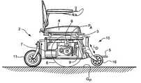
- FIG. 1is a side view of a powered wheelchair employing an active anti-tip system according to the present invention.
- FIG. 2is partial side view with a drive-wheel removed and portions of the frame structure broken-away to more clearly show the relevant internal components and assemblies including: a guide subassembly for mounting an anti-tip wheel, a bi-directional strut, and a linkage disposed between a drive train assembly and the guide for translating rotational into motion.
- FIG. 3is an enlarged side view of the anti-tip system wherein the anti-tip wheel is raised to an uppermost vertical position for negotiating curbs and/or other obstacles.
- FIG. 4is a cross sectional view taken substantially along line 4 — 4 of FIG. 3 .
- FIG. 5is an enlarged side view of the anti-tip system wherein the anti-tip wheel is disposed to a lowermost vertical position for stabilizing the wheelchair when traveling on or down sloping terrain or declined surfaces.
- FIG. 6 ais an enlarged side view of an alternate embodiment of the invention wherein the anti-tip wheel is biased to an operating position causing the wheel to contact the ground plane during routine operation.
- FIG. 6 bis an enlarged side view of an alternate embodiment of the anti-tip system wherein a compliant bearing mount is employed to improve the ride efficacy of the wheelchair, i.e., when impacting /climbing curbs and/or other obstacles.
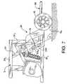
- FIG. 7is an enlarged side view of another embodiment of the inventive anti-tip system wherein the guide subassembly includes a rearwardly canted guide track having a detent formed therein for temporarily locking/maintaining the relative position of the anti-tip wheel relative to a ground plane.
- FIGS. 1 and 2depict a powered wheelchair 2 which has been adapted to accept and mount an anti-tip system 10 of the present invention.
- the inventive anti-tip systemmay be employed in any wheelchair which potentially benefits from stabilization about an effective pitch axis P A and/or enables or controls large angular excursions in relation to a ground plane G P .
- the powered wheelchair 2comprises an anti-tip system, identified generally by the numeral 10 in FIGS. 1 & 2 , a main structural frame 3 , a seat 4 (see FIG.
- Each drive train assembly 7is pivotally mounted to the main structural frame 3 about a pivot point 8 to effect relative rotation therebetween in response to torque applied by the drive motor or pitch motion of the frame about an effective pitch axis (not shown).
- a suspension assembly 9is provided for biasing an anti-tip wheel to a predetermined operating position and defines the effective pitch axis P A of the frame.
- the anti-tip system 10includes a mounting assembly 12 disposed in combination with the main structural frame 3 for mounting an anti-tip wheel 16 , and, in response to an acceleration of the wheelchair 2 , for causing the anti-tip wheel 16 to traverse in a direction (denoted as a two-headed arrow L D in FIG. 2 ) substantially normal to the ground plane G P .
- the suspension assembly 9is disposed in combination with the mounting assembly 12 for biasing the anti-tip wheel 16 to a predetermined operating position. While the operating position shown is one wherein the anti-tip wheel 16 is raised above and non-contiguous with the ground plane G P , it should be understood that the initial or neutral operating position may or may not contact the ground plane G P .
- the anti-tip wheel 16is raised relative to the ground plane to enable unrestricted yaw control/displacement of the wheelchair 2 .
- the anti-tip wheelis disposed in ground contact and is castored, i.e., supported for rotation about a vertical axis by one or more cylindrical bearings.
- the mounting assemblyincludes a guide subassembly 20 and a means 40 for converting the pivotal motion of the drive train assembly 7 into linear motion to be conveyed to the guide subassembly 20 .
- the guide subassembly 20includes at least one guide surface 24 a or 24 b which is substantially normal to the ground plane, pictorially illustrated by the X-Y plane of the coordinate system CS.
- the term “substantially normal”means that the linear surface 24 a , or 24 b defines an angle ⁇ which is within a range of between about ninety (90) degrees to about one hundred and forty (140) degrees relative to the ground plane, i.e., X-Y plane.
- the angle ⁇is obtuse and within a range of between about one-hundred (100) to about one-hundred and thirty (130) degrees.
- an angular orientation other than ninety (90) degreesi.e., an obtuse angle
- the linear guide subassembly 20preferably comprises a guide or guide track 24 disposed in combination with the main structural frame 3 (shown in FIG. 2 ). Further, the guide track 24 forms back-to-back roller guide surfaces 24 a , 24 b for guiding one or more pairs of opposed rollers 28 a , 28 b (see FIG. 3 b ). The opposing rollers 28 a , 28 b engage and capture the guide surfaces 24 a , 24 b and are rotatably supported within a roller cage 30 . Moreover, a suspension arm 34 is affixed to the roller cage 30 at one end thereof and rotatably mounts the anti-tip wheel (not shown in FIG. 3 ) at the other end thereof.
- the anti-tip wheel 16traverses a substantially linear path parallel to the guide surfaces 24 a , 24 b . While the guide surfaces 24 a , 24 b define a substantially linear path, it will be appreciated that the surfaces may define a slightly curvilinear path to compensate for other imposed motions. For example, the wheelchair itself causes the anti-tip wheels 16 to traverse an arcuate path. Consequently, to cause the anti-tip wheels 16 ′ to traverse a purely linear path, the guide surfaces may have a slightly convex curvature to compensate for such wheelchair motion.
- the translation means 40is provided for transferring the motion of the drive train assembly 7 (capable of pivoting about pivot point 8 ) to the guide subassembly 20 . More specifically, the translation means 40 includes a first linkage 42 rigidly affixed to the drive train assembly 7 , and a second linkage 44 pivotally mounting to the first linkage 42 at one end thereof and to the guide subassembly 20 at the other end. In the preferred embodiment, the second linkage 44 is pivotally mounted to the roller cage 30 of the guide subassembly 20 . Consequently, as the drive train assembly 7 pivots in response to an acceleration of the wheelchair 2 , the first linkage 42 pivots about pivot point 8 while the second linkage 44 pivots about the first linkage 42 and, additionally, follows the roller cage 30 .
- the suspension assembly 9 of the anti-tip system 10is preferably a bi-directional strut 50 pivotally mounted to both the guide track 24 (being supported via the main structural frame 3 ) and to the drive train assembly 7 .
- the strut 50includes a central collar 52 , an elongate tension member 56 disposed through the collar 52 and spring elements 62 a , 62 b disposed on each side of the collar 52 .
- the central collar 52is pivotally mounted to the guide track 24 about a pivot point 54 and the tension member 56 is pivotally mounted at one end 58 thereof to the drive train assembly 7 about a pivot point 66 .
- the drive train assembly 7includes an L-shaped bracket 68 for mounting the lower end 58 of the tension member 56 .
- each of the spring elements 62 a , 62 benvelop the tension member 56 and are tied to the collar 52 at one end thereof and to the ends of the tension member 56 at the other. Consequently, the tension member 56 may traverse internally of the spring elements 62 a , 62 b and the central collar 52 .
- the operation of the suspension assembly 9will be described in subsequent paragraphs when discussing the overall operation of the anti-tip system 10 .
- the anti-tip system 10positions the anti-tip wheel 16 in a predetermined operating position.
- the drive train assembly 7rotates in a counter-clockwise direction, depicted by the arrow labeled R A , about pivot point 8 (rotational directions correspond to the left profile view shown in FIGS. 2 and 3 ). Pivoting motion of the drive train assembly 7 effects a substantially vertical/upward displacement of the elongate tension member 56 relative to the collar 52 of the suspension assembly 9 . As the tension member 56 traverses, the lower spring element 62 b compresses biasing the entire mounting assembly 12 and drive train assembly 7 toward a neutral position.
- the first linkage member 42is also caused to rotate in a counter-clockwise direction, denoted by arrow R L1 in FIG. 3 .
- the second linkage member 44rotates in a clockwise direction, denoted by arrow R L2 relative to its pivot point 70 at the upper end of the first linkage member 42 .
- Rotation of both linkages 42 , 44causes the upward translation, denoted by arrow L DU , of the guide subassembly 20 and, consequently, the anti-tip wheel 16 .
- the anti-tip wheel 16is caused to rise above an obstacle to allow the main drive wheels 6 , which have a much larger diameter, to climb up and over the obstacle.
- the second spring element 62 bcauses the drive train and mounting assemblies 7 , 12 , to return to their original operating position, e.g., a neutral position.
- the drive train assembly 7pivots in a clockwise direction, shown as an arrow R D in FIG. 5 , about pivot point 8 .
- the rotation of the drive train assembly 7causes a substantially downward motion of the elongate tension member 56 , thereby compressing the first spring element 62 a .
- first and second linkage members 42 , 44rotate in a clockwise and counter-clockwise direction, denoted by arrows R L1 and R L2 , respectively, to effect downward translation, denoted by arrow L DD , of the guide subassembly 20 and, consequently, the anti-tip wheel 16 (see FIG. 2 ).
- Such downward motion of the anti-tip wheelfunctions to stabilize the wheelchair about the pitch axis P A ( FIG. 2 ) at a moment corresponding to a deceleration of the wheelchair 2 .
- the first spring element 62 abiases or returns the drive train and mounting assemblies 7 , 12 to an original or neutral operating position.
- FIG. 6 aillustrates an alternate embodiment of the active anti-tip system wherein each anti-tip wheel is contiguous with the ground plane G P .
- the suspension assembly 9biases the anti-tip wheels 16 ′ to effect ground contact while the wheel 16 ′ is pivot mounted to the suspension arm 34 about a vertical axis 34 SA .
- each anti-tip wheel 16 ′may include a vertical post (not shown) supported for rotation by one or more cylindrical bearings (also not shown) disposed within a cylindrical sleeve 34 S of the suspension arm 34 .
- the castored mount of the anti-tip wheels 16 ′enables the wheelchair to freely pivot about its vertical yaw axis to facilitate yaw control/motion.
- the guide subassembly 20may be rearwardly inclined to augment the obstacle climbing capability of the powered wheelchair 2 . That is, the guide subassembly 20 may be designed to cause the anti-tip wheel 16 to traverse linearly upward upon impacting an immobile object.
- a horizontal load L His reacted along the guide surface 29 b in a direction normal thereto.
- a substantially vertical component of the load L HVis developed to cause the suspension arm 34 and anti-tip wheel 16 to rise upwardly. This vertical travel augments the curb-climbing capability of the wheelchair.
- FIG. 6 bshows yet another embodiment wherein the mounting assembly 12 includes a compliant mount 12 C to facilitate inward displacement of the anti-tip wheel 16 ′, i.e., toward the main structural frame 3 or main drive wheels 6 , upon impacting a curb or obstacle CB.
- the compliant mount 12 Cis disposed between the suspension arm 34 and the vertical sleeve 34 S of the anti-tip wheel 16 ′ and comprises a resilient bearing EB disposed at the intersection of cross members 34 C1 , 34 C2 .
- the bearing EBcomprises a polygonally-shaped inner member, i.e., a shaft SP, a similarly shaped outer member (i.e., a housing HO), and a compliant elastomer EM disposed therebetween.
- the compliant elastomer EMis bonded to the linear surfaces LS of the shaft SP and the housing HO.
- the elastomer EMis formed by a plurality of elastomeric (e.g., rubber) elements that are preferably compressed between the inner shaft SP and the outer housing HO. As such, any lateral force tending to rotate the inner shaft SP relative to the outer housing HO produces deformation of the elastomer material EM.
- a resilient bearing EBsuch as the type described above is available from/sold by Rosta AG under the Tradename “Rubber Suspension System”.
- the compliant mount 34 Cfacilitates inward displacement of the anti-tip wheel 16 ′, i.e., via angular displacement of the vertical sleeve 34 S , but delimits or inhibits outward displacement of the anti-tip wheel 16 ′.
- Thismay be effected by any of a variety of structural combinations; for example, a simple abutment surface 34 AB may be provided between the horizontal and vertical members 34 C1 , 34 C2 to delimit the relative angular displacement of the members 34 C1 , 34 C2 and angular displacement of the vertical sleeve 34 S .
- the resilient bearing EB of the compliant mount 34 C segmentenables displacement in response to an externally applied impact load in the direction of load vector F H while limiting displacement in response to a load in the direction of load vector F R .
- the compliant segment 24 Ctherefore, augments the curb climbing ability of the anti-tip system 10 without degrading the pitch stabilizing capability thereof.
- the guide subassembly 20employs a track 24 which dually serves as: (i) a frontal support member for the main structural flame 3 and (ii) a mount for the anti-tip wheel 16 .
- the track 24may solely function as a mount for the anti-tip wheel 16 .
- the guide subassembly 20may employ a track 24 ′ which is affixed at its upper and lower ends to horizontal supports 3 H U , 3 H L of the frame 3 .
- the clevis arms 76 for pivotally mounting the suspension assembly 9is affixed to a frontal vertical support 3 V F of the frame 3 .
- this configurationpermits greater design flexibility when determining the angle ⁇ of the guide surfaces 24 a′ , 24 b′ .
- the track 24 ′may slope at a substantially greater angle, e.g., 135 degrees, without adversely impacting the structure of the frame 3 .
- the advantage of such angular positionrelates to an improvement in the curb-climbing ability of the powered wheelchair.
- a detent 78for momentarily holding a predefined linear position of the guide subassembly 20 and, consequently, maintaining the position of the anti-tip wheel relative to the ground plane G P .
- the detent 78may be formed along the aft guide surface 24 b′ such that the aft lower roller 28 b A of the guide subassembly 20 is caused to engage the detent 78 upon alignment therewith.
- the wheelchairmay be stabilized ( 4 or 6 wheels in ground contact) when an occupant puts weight on a footrest assembly 80 , i.e., getting on or off of the wheelchair.
- the rollerWhen torque levels reach a threshold level (chosen as a function of the design requirements), the roller is caused to disengage the detent 78 .
- the detent 78may be formed at any position or along either of the guide surfaces 24 a′ , 24 b′ depending upon where, i.e., at what position, the guide subassembly 20 is to be temporarily locked/maintained in position.
- the active anti-tip system of the present inventionprovides a mounting assembly 12 which enhances the curb-climbing ability of a powered wheelchair by increasing the displacement of the anti-tip wheel 16 . That is, the vertical displacement of the ant-tip wheel 16 is increased without lengthening a suspension arm (as required by prior art anti-tip system designs). Furthermore, the increased displacement provided by the mounting assembly 12 enables enhanced pitch stability by causing the anti-tip wheel 16 to be lowered relative to the underlying ground plane G P . That is, when the wheelchair 2 may be traveling on declined surfaces, the anti-tip wheel 16 may be positioned proximal to the ground plane i.e., at the required moment, to enhance pitch stability. With respect to the embodiment employing castored anti-tip wheels 16 ′, the invention is capable of providing an immediate pitch stabilization response, i.e., eliminates the lag in response where the anti-tip wheels are raised off the ground.
- the mounting arrangement 12only requires a single suspension assembly 9 , e.g., bi-directional strut, to bias the anti-tip wheel 16 to a predetermined operating position, i.e., fully-down, fully-up or a neutral position.
- the anti-tip system 10requires fewer components to replace and/or maintain.
- the compliant mount 34 C thereofis capable of absorbing a portion of an externally applied impact load to improve the ride comfort. Additionally, the inward displacement enabled by the mount 34 C changes the angle that the curb CB impacts or addresses an anti-tip 16 ′ and shortens the distance between the curb CB and the main drive wheels 6 .
- a more favorable impact anglecan produce a vertical component of force for augmenting the curb climbing ability of the wheelchair.
- the wheels 6may engage the curb CB before the wheelchair 2 beings to lose its forward momentum/inertia.
- the anti-tip system of the present inventionprovides greater design flexibility with respect to the location, angular position and/or mounting of the anti-tip wheel 16 and the ability to design to meet various requirements.
- the anti-tip wheel 16may be located at nearly any operational position without significant modifications to the design of the mounting arrangement 12 or to the powered wheelchair 2 .
- the linkages 42 , 44 or guide track 24will be required.
- the translation means 40may comprise a slotted link/pin arrangement.
- a drive linkmay be rigidly affixed to the pivoting drive train assembly and have an elongate slot formed therein.
- a pin disposed in combination with the guide subassemblymay accept and engage the elongate slot such that arcuate motion of the drive link effects translation of the guide subassembly. That is, the slot accommodates foreshortening affects, i.e., in the longitudinal direction, of the rotating drive link.
- opposing rollers 28 a , 28 bare shown to support and mount the suspension arm 34 /anti-tip wheel 16 to a guide track 24 , it should be appreciated that any bearing configuration capable of rolling or sliding upon a guide surface may be employed.
- a sliding track having a generally inverted T-shaped cross sectional configurationmay be employed with a sliding T-shaped bearing block disposed therein. Consequently the bearing block is captured within the T-shaped track or slot and mounted to the suspension arm of the anti-tip wheel.
- the present inventionemploys a bi-directional strut 50 to suspend the drive train and mounting assemblies 7 , 12 , it will be appreciated that other suspension devices may be employed. Generally, any device or combination of devices which suspend the drive train assembly 7 and the mounting assembly 12 , whether independently or in combination, relative to the main structural frame 3 may be utilized.
Landscapes
- Health & Medical Sciences (AREA)
- Life Sciences & Earth Sciences (AREA)
- Animal Behavior & Ethology (AREA)
- General Health & Medical Sciences (AREA)
- Public Health (AREA)
- Veterinary Medicine (AREA)
- Vehicle Body Suspensions (AREA)
- Handcart (AREA)
Abstract
Description
Claims (23)
Priority Applications (1)
| Application Number | Priority Date | Filing Date | Title |
|---|---|---|---|
| US10/943,713US7232008B2 (en) | 2003-10-08 | 2004-09-17 | Active anti-tip wheels for power wheelchair |
Applications Claiming Priority (3)
| Application Number | Priority Date | Filing Date | Title |
|---|---|---|---|
| US50957103P | 2003-10-08 | 2003-10-08 | |
| US55399804P | 2004-03-16 | 2004-03-16 | |
| US10/943,713US7232008B2 (en) | 2003-10-08 | 2004-09-17 | Active anti-tip wheels for power wheelchair |
Publications (2)
| Publication Number | Publication Date |
|---|---|
| US20050077694A1 US20050077694A1 (en) | 2005-04-14 |
| US7232008B2true US7232008B2 (en) | 2007-06-19 |
Family
ID=34316849
Family Applications (1)
| Application Number | Title | Priority Date | Filing Date |
|---|---|---|---|
| US10/943,713Expired - LifetimeUS7232008B2 (en) | 2003-10-08 | 2004-09-17 | Active anti-tip wheels for power wheelchair |
Country Status (3)
| Country | Link |
|---|---|
| US (1) | US7232008B2 (en) |
| EP (1) | EP1522292A3 (en) |
| CA (1) | CA2483973A1 (en) |
Cited By (24)
| Publication number | Priority date | Publication date | Assignee | Title |
|---|---|---|---|---|
| US20050038497A1 (en)* | 2003-08-11 | 2005-02-17 | Scimed Life Systems, Inc. | Deformation medical device without material deformation |
| US20060076169A1 (en)* | 2004-08-14 | 2006-04-13 | Thomas Brendel | Running wheel arrangement for a wheelchair |
| US20070039766A1 (en)* | 2005-08-18 | 2007-02-22 | Jackson Mark A | Midwheel drive wheelchair with independent front and rear suspension |
| US20080157513A1 (en)* | 2006-12-29 | 2008-07-03 | Merits Health Products Co., Ltd. | Anti-tip assembly for a power wheelchair |
| US20080169136A1 (en)* | 2004-04-08 | 2008-07-17 | Levo Ag Wohlen | Wheelchair With A Middle Wheel Drive, In Particular Raising Wheelchair |
| US20080264702A1 (en)* | 2007-04-25 | 2008-10-30 | Merits Health Products Co., Ltd. | Power wheelchair |
| US20110083913A1 (en)* | 2009-10-09 | 2011-04-14 | Invacare Corporation | Wheelchair suspension |
| US20140265283A1 (en)* | 2013-03-15 | 2014-09-18 | Jeff Tad Clifton | Service Vehicle Operation Training System and Method |
| US8851214B2 (en) | 2010-07-15 | 2014-10-07 | Permobil Ab | Electric mid-wheel drive wheelchair |
| US8910975B2 (en) | 2007-02-14 | 2014-12-16 | Invacare Corporation | Wheelchair with suspension |
| US8925943B2 (en) | 2001-10-10 | 2015-01-06 | Invacare Corp. | Wheelchair suspension |
| WO2015095221A2 (en) | 2013-12-16 | 2015-06-25 | Mulhern James P | Elevated height wheelchair |
| US9149398B2 (en) | 2000-10-27 | 2015-10-06 | Invacare Corporation | Obstacle traversing wheelchair |
| US9308143B2 (en) | 2012-02-15 | 2016-04-12 | Invacare Corporation | Wheelchair suspension |
| US9364377B2 (en) | 2002-10-25 | 2016-06-14 | Invacare Corporation | Suspension for wheeled vehicles |
| US9603762B2 (en) | 2007-02-08 | 2017-03-28 | Invacare Corporation | Wheelchair suspension |
| US11123242B2 (en)* | 2018-11-22 | 2021-09-21 | Invacare International Gmbh | Motorized wheelchair chassis and motorized wheelchair comprising the same |
| US11191685B2 (en) | 2016-02-27 | 2021-12-07 | Pride Mobility Products Corporation | Adjustable height wheelchair |
| US11213441B2 (en) | 2002-10-25 | 2022-01-04 | Invacare Corporation | Suspension for wheeled vehicles |
| US11419773B2 (en) | 2019-11-09 | 2022-08-23 | The Onward Project, LLC | Convertible wheelchair |
| US11903887B2 (en) | 2020-02-25 | 2024-02-20 | Invacare Corporation | Wheelchair and suspension systems |
| US11957631B2 (en) | 2022-07-13 | 2024-04-16 | Invacare Corporation | Wheelchair and suspension systems |
| USD1033279S1 (en) | 2022-08-22 | 2024-07-02 | Three Oceans, LLC | Scooter |
| US12409085B2 (en) | 2022-07-07 | 2025-09-09 | Permobil Ab | Powered midwheel drive wheelchair with standing capability |
Families Citing this family (17)
| Publication number | Priority date | Publication date | Assignee | Title |
|---|---|---|---|---|
| US7066290B2 (en) | 2001-10-19 | 2006-06-27 | Invacare Corp. | Wheelchair suspension having pivotal motor mount |
| US7264272B2 (en)* | 2004-03-16 | 2007-09-04 | Pride Mobility Products Corporation | Bi-directional anti-tip system for powered wheelchairs |
| US20060076747A1 (en)* | 2004-10-08 | 2006-04-13 | Sunrise Medical Hhg Inc. | Wheelchair suspension system |
| US20060076748A1 (en)* | 2004-10-08 | 2006-04-13 | Sunrise Medical Hhg Inc. | Wheelchair with damping mechanism |
| US20060091663A1 (en)* | 2004-10-21 | 2006-05-04 | Sunrise Medical Hhg Inc. | Wheelchair with telescopic anti-tip wheel |
| EP1943995A1 (en) | 2007-01-12 | 2008-07-16 | Invacare International Sàrl | A wheeled conveyance with suspension arms for wheels |
| FR2915091B1 (en)* | 2007-04-20 | 2009-07-24 | Lfp Dev Soc Par Actions Simpli | VERTICALIZING ARMCHAIR WITH GROUND FLOOR OF VARIABLE FOOTREST |
| US9398990B2 (en) | 2011-07-06 | 2016-07-26 | W Mark Richter | Motion-based power assist system for wheelchairs |
| TWI514335B (en)* | 2013-01-08 | 2015-12-21 | Univ Nat Taiwan | Early warning method and device for prevention of backward turning over of wheelchair |
| US9144525B2 (en)* | 2013-03-14 | 2015-09-29 | Max Mobility, Llc. | Motion assistance system for wheelchairs |
| US9795524B2 (en) | 2015-02-24 | 2017-10-24 | Max Mobility, Llc | Assistive driving system for a wheelchair |
| DE102016118037A1 (en) | 2016-09-23 | 2018-03-29 | Otto Bock Mobility Solutions Gmbh | wheelchair |
| US10167051B1 (en) | 2017-12-12 | 2019-01-01 | Max Mobility, Llc | Assistive driving system for a wheelchair and method for controlling assistive driving system |
| CN110469175A (en)* | 2019-07-31 | 2019-11-19 | 山东博创智能停车设备有限公司 | No dodge type stereoscopic parking lot anti-dumping running gear |
| CN110700601B (en)* | 2019-10-15 | 2021-08-20 | 北京城建北方集团有限公司 | Telescopic unloading platform |
| AU2021305625A1 (en) | 2020-07-08 | 2023-02-02 | Pride Mobility Products Corporation | Anti-tip motorized vehicle |
| CN119385771A (en)* | 2024-11-11 | 2025-02-07 | 安维车件(厦门)有限公司 | Anti-rollover device and wheelchair |
Citations (40)
| Publication number | Priority date | Publication date | Assignee | Title |
|---|---|---|---|---|
| US1773254A (en) | 1928-12-07 | 1930-08-19 | Joseph L Becker | Stabilizer for road-grading machines |
| US3520378A (en) | 1966-06-23 | 1970-07-14 | Reginald Arthur Slay | Motor-driven wheeled vehicles |
| FR2215054A5 (en) | 1973-01-23 | 1974-08-19 | Folco Zambelli Gian Matteo | |
| US3848883A (en) | 1973-08-08 | 1974-11-19 | S Breacain | Wheelchair anti-tip apparatus |
| US4128137A (en) | 1976-02-24 | 1978-12-05 | National Research Development Corporation | Peripatetic vehicles |
| FR2399822A1 (en) | 1977-08-09 | 1979-03-09 | Dupont Lit Sa | Folding wheel chair for handicapped people - consists of frame on two drive wheels, with seat mounted by parallel arms raised and lowered by jack |
| US4245847A (en) | 1979-05-24 | 1981-01-20 | Christopher Knott | Wheelchair |
| US4437678A (en) | 1980-08-06 | 1984-03-20 | Schultz Barry J | Vehicular suspension |
| WO1990006097A1 (en) | 1988-11-28 | 1990-06-14 | Mercado Medic Ab | A wheelchair with a six-wheel chassis |
| US5435404A (en) | 1992-07-31 | 1995-07-25 | Garin, Iii; Paul V. | Powered mobility chair for individual |
| US5564512A (en) | 1992-12-17 | 1996-10-15 | Richard Van Seenus Nederland B.V. | Wheelchair |
| US5772237A (en) | 1996-05-21 | 1998-06-30 | Teftec Corporation | Suspension system for powered wheelchair |
| US5848658A (en) | 1997-10-06 | 1998-12-15 | Invacare Corporation | Adjustable front wheel stabilizer for power wheelchair |
| US5855387A (en) | 1997-05-01 | 1999-01-05 | Caribbean Billing International, Ltd. | Wheel chair with independent suspension |
| US5964473A (en) | 1994-11-18 | 1999-10-12 | Degonda-Rehab S.A. | Wheelchair for transporting or assisting the displacement of at least one user, particularly for handicapped person |
| US6041876A (en)* | 1997-10-06 | 2000-03-28 | Invacare Corporation | Anti-tip assembly for power wheelchair |
| US6047979A (en) | 1998-04-03 | 2000-04-11 | Geer Products Ltd. | Wheelchair anti-tipping device |
| US6062600A (en) | 1996-07-17 | 2000-05-16 | Deka Products Limited Partnership | Anti-tipping mechanism |
| WO2000053142A1 (en) | 1999-03-09 | 2000-09-14 | Sunrise Medical Limited | Improvements in vehicles |
| WO2000054718A1 (en) | 1999-03-17 | 2000-09-21 | Permobil Ab | An anti-tip device for a wheelchair |
| US6129165A (en) | 1996-07-03 | 2000-10-10 | Pride Mobility Products, Corporation | Curb-climbing power wheelchair |
| US6135222A (en)* | 1998-09-11 | 2000-10-24 | Nissin Medical Industries Co., Ltd. | Installing structure for an electrically-driven wheelchair |
| US6196343B1 (en) | 1998-10-23 | 2001-03-06 | Rollerchair Pty Ltd. | Mid-wheel drive wheelchair |
| JP2001104391A (en) | 1999-10-08 | 2001-04-17 | Yamaha Motor Co Ltd | Wheelchair |
| WO2001029438A1 (en) | 1999-10-20 | 2001-04-26 | Howard Hoose | Vehicle suspension and bearing therefor |
| US6234507B1 (en) | 1998-08-14 | 2001-05-22 | Sunrise Medical Hhg Inc. | Suspension system for a wheelchair |
| US6357793B1 (en) | 1999-10-29 | 2002-03-19 | Sunrise Medical Hhg Inc. | Anti-tip wheel |
| US6460641B1 (en) | 2000-06-29 | 2002-10-08 | Invacare Corporation | Mid-wheel drive wheelchair with front wheel multiple bias suspension and anti-tip assembly |
| US6533306B2 (en) | 2001-01-18 | 2003-03-18 | Pride Mobility Products Corporation | Adjustable height anti-tip wheels for a power wheelchair |
| US6543798B2 (en) | 2000-04-04 | 2003-04-08 | Pride Mobility Products Corporation | Anti-tip caster suspension for a wheelchair |
| US20030075365A1 (en) | 2001-10-19 | 2003-04-24 | Fought Gerald E. | Wheelchair suspension having pivotal motor mount |
| US6554086B1 (en) | 2000-10-27 | 2003-04-29 | Invacare Corporation | Obstacle traversing wheelchair |
| US20040004342A1 (en) | 2002-04-30 | 2004-01-08 | Mulhern James P. | Rear wheel drive power wheelchair with ground-contacting anti-tip wheels |
| US20040035627A1 (en) | 2002-06-05 | 2004-02-26 | Richey Joseph B. | Mid-wheel drive scooter |
| US20040046358A1 (en) | 2002-09-09 | 2004-03-11 | White Gerald J. | Stabilizing system for a reclinable wheelchair |
| US6712369B2 (en) | 2002-02-28 | 2004-03-30 | Pihsiang Machinery Mfg. Co., Ltd. | Anti-turnover mechanism of electrical wheelchair |
| US20040060748A1 (en) | 2001-10-10 | 2004-04-01 | Molnar James H. | Wheelchair suspension |
| US20040251649A1 (en) | 2003-06-13 | 2004-12-16 | Wu Daniel P.H. | Suspension structure for front wheel assembly of wheelchair |
| US6851711B2 (en) | 2002-08-16 | 2005-02-08 | Invacare Corporation | Vehicle having an anti-dive/lockout mechanism |
| US7104346B2 (en)* | 2003-03-25 | 2006-09-12 | Schaffner Walter E | Power wheelchair |
Family Cites Families (2)
| Publication number | Priority date | Publication date | Assignee | Title |
|---|---|---|---|---|
| US6357799B1 (en)* | 1999-02-09 | 2002-03-19 | Etsuo Shibata | Printed matter |
| DE10026021A1 (en)* | 2000-05-25 | 2001-11-29 | Hilti Ag | Tool holder for a drill bit |
- 2004
- 2004-09-17USUS10/943,713patent/US7232008B2/ennot_activeExpired - Lifetime
- 2004-10-05CACA002483973Apatent/CA2483973A1/ennot_activeAbandoned
- 2004-10-07EPEP04256202Apatent/EP1522292A3/ennot_activeWithdrawn
Patent Citations (43)
| Publication number | Priority date | Publication date | Assignee | Title |
|---|---|---|---|---|
| US1773254A (en) | 1928-12-07 | 1930-08-19 | Joseph L Becker | Stabilizer for road-grading machines |
| US3520378A (en) | 1966-06-23 | 1970-07-14 | Reginald Arthur Slay | Motor-driven wheeled vehicles |
| FR2215054A5 (en) | 1973-01-23 | 1974-08-19 | Folco Zambelli Gian Matteo | |
| US3848883A (en) | 1973-08-08 | 1974-11-19 | S Breacain | Wheelchair anti-tip apparatus |
| US4128137A (en) | 1976-02-24 | 1978-12-05 | National Research Development Corporation | Peripatetic vehicles |
| FR2399822A1 (en) | 1977-08-09 | 1979-03-09 | Dupont Lit Sa | Folding wheel chair for handicapped people - consists of frame on two drive wheels, with seat mounted by parallel arms raised and lowered by jack |
| US4245847A (en) | 1979-05-24 | 1981-01-20 | Christopher Knott | Wheelchair |
| US4437678A (en) | 1980-08-06 | 1984-03-20 | Schultz Barry J | Vehicular suspension |
| WO1990006097A1 (en) | 1988-11-28 | 1990-06-14 | Mercado Medic Ab | A wheelchair with a six-wheel chassis |
| US5435404A (en) | 1992-07-31 | 1995-07-25 | Garin, Iii; Paul V. | Powered mobility chair for individual |
| US5564512A (en) | 1992-12-17 | 1996-10-15 | Richard Van Seenus Nederland B.V. | Wheelchair |
| US5964473A (en) | 1994-11-18 | 1999-10-12 | Degonda-Rehab S.A. | Wheelchair for transporting or assisting the displacement of at least one user, particularly for handicapped person |
| US5772237A (en) | 1996-05-21 | 1998-06-30 | Teftec Corporation | Suspension system for powered wheelchair |
| US6129165A (en) | 1996-07-03 | 2000-10-10 | Pride Mobility Products, Corporation | Curb-climbing power wheelchair |
| US6062600A (en) | 1996-07-17 | 2000-05-16 | Deka Products Limited Partnership | Anti-tipping mechanism |
| US6241391B1 (en) | 1997-04-28 | 2001-06-05 | Howard Hoose | Vehicle suspension and bearing therefor |
| US5855387A (en) | 1997-05-01 | 1999-01-05 | Caribbean Billing International, Ltd. | Wheel chair with independent suspension |
| US5848658A (en) | 1997-10-06 | 1998-12-15 | Invacare Corporation | Adjustable front wheel stabilizer for power wheelchair |
| US6041876A (en)* | 1997-10-06 | 2000-03-28 | Invacare Corporation | Anti-tip assembly for power wheelchair |
| US6047979A (en) | 1998-04-03 | 2000-04-11 | Geer Products Ltd. | Wheelchair anti-tipping device |
| US6234507B1 (en) | 1998-08-14 | 2001-05-22 | Sunrise Medical Hhg Inc. | Suspension system for a wheelchair |
| US6135222A (en)* | 1998-09-11 | 2000-10-24 | Nissin Medical Industries Co., Ltd. | Installing structure for an electrically-driven wheelchair |
| US6196343B1 (en) | 1998-10-23 | 2001-03-06 | Rollerchair Pty Ltd. | Mid-wheel drive wheelchair |
| WO2000053142A1 (en) | 1999-03-09 | 2000-09-14 | Sunrise Medical Limited | Improvements in vehicles |
| WO2000054718A1 (en) | 1999-03-17 | 2000-09-21 | Permobil Ab | An anti-tip device for a wheelchair |
| JP2001104391A (en) | 1999-10-08 | 2001-04-17 | Yamaha Motor Co Ltd | Wheelchair |
| WO2001029438A1 (en) | 1999-10-20 | 2001-04-26 | Howard Hoose | Vehicle suspension and bearing therefor |
| US6357793B1 (en) | 1999-10-29 | 2002-03-19 | Sunrise Medical Hhg Inc. | Anti-tip wheel |
| US6543798B2 (en) | 2000-04-04 | 2003-04-08 | Pride Mobility Products Corporation | Anti-tip caster suspension for a wheelchair |
| US6460641B1 (en) | 2000-06-29 | 2002-10-08 | Invacare Corporation | Mid-wheel drive wheelchair with front wheel multiple bias suspension and anti-tip assembly |
| US6554086B1 (en) | 2000-10-27 | 2003-04-29 | Invacare Corporation | Obstacle traversing wheelchair |
| US6533306B2 (en) | 2001-01-18 | 2003-03-18 | Pride Mobility Products Corporation | Adjustable height anti-tip wheels for a power wheelchair |
| US20040060748A1 (en) | 2001-10-10 | 2004-04-01 | Molnar James H. | Wheelchair suspension |
| US7040429B2 (en)* | 2001-10-10 | 2006-05-09 | Invacare Corporation | Wheelchair suspension |
| US20030075365A1 (en) | 2001-10-19 | 2003-04-24 | Fought Gerald E. | Wheelchair suspension having pivotal motor mount |
| US7066290B2 (en)* | 2001-10-19 | 2006-06-27 | Invacare Corp. | Wheelchair suspension having pivotal motor mount |
| US6712369B2 (en) | 2002-02-28 | 2004-03-30 | Pihsiang Machinery Mfg. Co., Ltd. | Anti-turnover mechanism of electrical wheelchair |
| US20040004342A1 (en) | 2002-04-30 | 2004-01-08 | Mulhern James P. | Rear wheel drive power wheelchair with ground-contacting anti-tip wheels |
| US20040035627A1 (en) | 2002-06-05 | 2004-02-26 | Richey Joseph B. | Mid-wheel drive scooter |
| US6851711B2 (en) | 2002-08-16 | 2005-02-08 | Invacare Corporation | Vehicle having an anti-dive/lockout mechanism |
| US20040046358A1 (en) | 2002-09-09 | 2004-03-11 | White Gerald J. | Stabilizing system for a reclinable wheelchair |
| US7104346B2 (en)* | 2003-03-25 | 2006-09-12 | Schaffner Walter E | Power wheelchair |
| US20040251649A1 (en) | 2003-06-13 | 2004-12-16 | Wu Daniel P.H. | Suspension structure for front wheel assembly of wheelchair |
Cited By (64)
| Publication number | Priority date | Publication date | Assignee | Title |
|---|---|---|---|---|
| US9149398B2 (en) | 2000-10-27 | 2015-10-06 | Invacare Corporation | Obstacle traversing wheelchair |
| US9987177B2 (en) | 2000-10-27 | 2018-06-05 | Invacare Corporation | Obstacle traversing wheelchair |
| US8925943B2 (en) | 2001-10-10 | 2015-01-06 | Invacare Corp. | Wheelchair suspension |
| US9370455B2 (en) | 2001-10-10 | 2016-06-21 | Invacare Corporation | Wheelchair suspension |
| US9364377B2 (en) | 2002-10-25 | 2016-06-14 | Invacare Corporation | Suspension for wheeled vehicles |
| US10512572B2 (en) | 2002-10-25 | 2019-12-24 | Invacare Corporation | Suspension for wheeled vehicles |
| US11213441B2 (en) | 2002-10-25 | 2022-01-04 | Invacare Corporation | Suspension for wheeled vehicles |
| US9925100B2 (en) | 2002-10-25 | 2018-03-27 | Invacare Corporation | Suspension for wheeled vehicles |
| US20050038497A1 (en)* | 2003-08-11 | 2005-02-17 | Scimed Life Systems, Inc. | Deformation medical device without material deformation |
| US20080169136A1 (en)* | 2004-04-08 | 2008-07-17 | Levo Ag Wohlen | Wheelchair With A Middle Wheel Drive, In Particular Raising Wheelchair |
| US20060076169A1 (en)* | 2004-08-14 | 2006-04-13 | Thomas Brendel | Running wheel arrangement for a wheelchair |
| US7341123B2 (en)* | 2004-08-14 | 2008-03-11 | Otto Bock Healthcare Ip Gmbh & Co., Kg | Running wheel arrangement for a wheelchair |
| US20070039766A1 (en)* | 2005-08-18 | 2007-02-22 | Jackson Mark A | Midwheel drive wheelchair with independent front and rear suspension |
| US7896394B2 (en)* | 2005-08-18 | 2011-03-01 | Sunrise Medical Hhg, Inc. | Midwheel drive wheelchair with independent front and rear suspension |
| US20080157513A1 (en)* | 2006-12-29 | 2008-07-03 | Merits Health Products Co., Ltd. | Anti-tip assembly for a power wheelchair |
| US10912690B2 (en) | 2007-02-08 | 2021-02-09 | Invacare Corporation | Wheelchair suspension |
| US11819464B2 (en) | 2007-02-08 | 2023-11-21 | Invacare Corporation | Wheelchair suspension |
| US11464687B2 (en) | 2007-02-08 | 2022-10-11 | Invacare Coporation | Wheelchair suspension |
| US10265229B2 (en) | 2007-02-08 | 2019-04-23 | Invacare Corporation | Wheelchair suspension |
| US9603762B2 (en) | 2007-02-08 | 2017-03-28 | Invacare Corporation | Wheelchair suspension |
| US9346335B2 (en) | 2007-02-14 | 2016-05-24 | Invacare Corporation | Stability control system |
| US11097589B2 (en) | 2007-02-14 | 2021-08-24 | Invacare Corporation | Stability control system |
| US10532626B2 (en) | 2007-02-14 | 2020-01-14 | Invacare Corporation | Stability control system |
| US11535078B2 (en) | 2007-02-14 | 2022-12-27 | Invacare Corporation | Stability control system |
| US11850906B2 (en) | 2007-02-14 | 2023-12-26 | Invacare Corporation | Stability control system |
| US8910975B2 (en) | 2007-02-14 | 2014-12-16 | Invacare Corporation | Wheelchair with suspension |
| US9827823B2 (en) | 2007-02-14 | 2017-11-28 | Invacare Corporation | Stability control system |
| US7775307B2 (en)* | 2007-04-25 | 2010-08-17 | Merite Health Products Co., Ltd. | Power wheelchair |
| US20080264702A1 (en)* | 2007-04-25 | 2008-10-30 | Merits Health Products Co., Ltd. | Power wheelchair |
| US20210369518A1 (en)* | 2009-10-09 | 2021-12-02 | Invacare Corporation | Wheelchair suspension |
| US9913768B2 (en) | 2009-10-09 | 2018-03-13 | Invacare Corporation | Wheelchair suspension |
| US9010470B2 (en) | 2009-10-09 | 2015-04-21 | Invacare Corporation | Wheelchair suspension |
| US11096845B2 (en) | 2009-10-09 | 2021-08-24 | Invacare Corporation | Wheelchair suspension |
| US11857470B2 (en)* | 2009-10-09 | 2024-01-02 | Invacare Corporation | Wheelchair suspension |
| US20110083913A1 (en)* | 2009-10-09 | 2011-04-14 | Invacare Corporation | Wheelchair suspension |
| US9320661B2 (en) | 2010-07-15 | 2016-04-26 | Permobil Ab | Electric mid-wheel drive wheelchair |
| US8851214B2 (en) | 2010-07-15 | 2014-10-07 | Permobil Ab | Electric mid-wheel drive wheelchair |
| US9308143B2 (en) | 2012-02-15 | 2016-04-12 | Invacare Corporation | Wheelchair suspension |
| US9700470B2 (en) | 2012-02-15 | 2017-07-11 | Invacare Corporation | Wheelchair suspension |
| US10434019B2 (en) | 2012-02-15 | 2019-10-08 | Invacare Corporation | Wheelchair suspension |
| US11234875B2 (en) | 2012-02-15 | 2022-02-01 | Invacare Corporation | Wheelchair suspension |
| US20140265283A1 (en)* | 2013-03-15 | 2014-09-18 | Jeff Tad Clifton | Service Vehicle Operation Training System and Method |
| US11571345B2 (en) | 2013-12-16 | 2023-02-07 | Pride Mobility Products Corporation | Elevated height wheelchair |
| WO2015095221A2 (en) | 2013-12-16 | 2015-06-25 | Mulhern James P | Elevated height wheelchair |
| US20190029899A1 (en)* | 2013-12-16 | 2019-01-31 | Pride Mobility Products Corporation | Elevated Height Wheelchair |
| US10130532B2 (en)* | 2013-12-16 | 2018-11-20 | Pride Mobility Products Corporation | Elevated height wheelchair |
| US20180055702A1 (en)* | 2013-12-16 | 2018-03-01 | Pride Mobility Products Corporation | Elevated Height Wheelchair |
| US10561548B1 (en) | 2013-12-16 | 2020-02-18 | Pride Mobility Products Corporation | Elevated height wheelchair |
| US11141330B2 (en) | 2013-12-16 | 2021-10-12 | Pride Mobility Products Corporation | Elevated height wheelchair |
| US9808383B2 (en) | 2013-12-16 | 2017-11-07 | Pride Mobility Products Corporation | Elevated height wheelchair |
| US10828212B2 (en)* | 2013-12-16 | 2020-11-10 | Pride Mobility Products Corporation | Elevated height wheelchair |
| US10687997B2 (en)* | 2013-12-16 | 2020-06-23 | Pride Mobility Products Corporation | Elevated height wheelchair |
| US20200179194A1 (en)* | 2013-12-16 | 2020-06-11 | Pride Mobility Products Corporation | Elevated Height Wheelchair |
| US9351889B2 (en) | 2013-12-16 | 2016-05-31 | Pride Mobility Products Corporation | Elevated height wheelchair |
| US20170156952A1 (en)* | 2013-12-16 | 2017-06-08 | Pride Mobility Products Corporation | Elevated height wheelchair |
| US9566200B2 (en) | 2013-12-16 | 2017-02-14 | Pride Mobility Products Corporation | Elevated height wheelchair |
| US10588797B2 (en)* | 2013-12-16 | 2020-03-17 | Pride Mobility Products Corporation | Elevated height wheelchair |
| US11191685B2 (en) | 2016-02-27 | 2021-12-07 | Pride Mobility Products Corporation | Adjustable height wheelchair |
| US11123242B2 (en)* | 2018-11-22 | 2021-09-21 | Invacare International Gmbh | Motorized wheelchair chassis and motorized wheelchair comprising the same |
| US11419773B2 (en) | 2019-11-09 | 2022-08-23 | The Onward Project, LLC | Convertible wheelchair |
| US11903887B2 (en) | 2020-02-25 | 2024-02-20 | Invacare Corporation | Wheelchair and suspension systems |
| US12409085B2 (en) | 2022-07-07 | 2025-09-09 | Permobil Ab | Powered midwheel drive wheelchair with standing capability |
| US11957631B2 (en) | 2022-07-13 | 2024-04-16 | Invacare Corporation | Wheelchair and suspension systems |
| USD1033279S1 (en) | 2022-08-22 | 2024-07-02 | Three Oceans, LLC | Scooter |
Also Published As
| Publication number | Publication date |
|---|---|
| CA2483973A1 (en) | 2005-04-08 |
| US20050077694A1 (en) | 2005-04-14 |
| EP1522292A2 (en) | 2005-04-13 |
| EP1522292A3 (en) | 2005-07-27 |
Similar Documents
| Publication | Publication Date | Title |
|---|---|---|
| US7232008B2 (en) | Active anti-tip wheels for power wheelchair | |
| US7264272B2 (en) | Bi-directional anti-tip system for powered wheelchairs | |
| US7316282B2 (en) | Anti-tip system for wheelchairs | |
| US11857470B2 (en) | Wheelchair suspension | |
| US11819464B2 (en) | Wheelchair suspension | |
| US7389835B2 (en) | Active anti-tip system for power wheelchairs | |
| US6234507B1 (en) | Suspension system for a wheelchair | |
| AU773976B2 (en) | Anti-tip caster suspension for a wheelchair | |
| EP2332753B1 (en) | Obstacle traversing wheelchair | |
| US5899475A (en) | Vehicle having wheels and castors | |
| JP2018528037A (en) | Mobility wheelchair | |
| GB1578742A (en) | Peripatetic vehicles | |
| WO2000008910A2 (en) | Resilient suspension system for a wheelchair | |
| Taguchi | Enhanced wheel system for step climbing | |
| US10568788B2 (en) | Mid-wheel drive wheelchair and seat unit | |
| AU2014202550B2 (en) | Wheelchair suspension |
Legal Events
| Date | Code | Title | Description |
|---|---|---|---|
| AS | Assignment | Owner name:PRIDE MOBILITY PRODUCTS CORPORATION, PENNSYLVANIA Free format text:ASSIGNMENT OF ASSIGNORS INTEREST;ASSIGNORS:LEVI, RONALD;MULHERN, JAMES P.;REEL/FRAME:015986/0310 Effective date:20040913 | |
| STCF | Information on status: patent grant | Free format text:PATENTED CASE | |
| CC | Certificate of correction | ||
| AS | Assignment | Owner name:MANUFACTURERS AND TRADERS TRUST COMPANY, NEW YORK Free format text:SECURITY AGREEMENT;ASSIGNOR:PRIDE MOBILITY PRODUCTS CORPORATION;REEL/FRAME:022408/0671 Effective date:20081107 Owner name:MANUFACTURERS AND TRADERS TRUST COMPANY,NEW YORK Free format text:SECURITY AGREEMENT;ASSIGNOR:PRIDE MOBILITY PRODUCTS CORPORATION;REEL/FRAME:022408/0671 Effective date:20081107 | |
| FPAY | Fee payment | Year of fee payment:4 | |
| FPAY | Fee payment | Year of fee payment:8 | |
| MAFP | Maintenance fee payment | Free format text:PAYMENT OF MAINTENANCE FEE, 12TH YEAR, LARGE ENTITY (ORIGINAL EVENT CODE: M1553); ENTITY STATUS OF PATENT OWNER: LARGE ENTITY Year of fee payment:12 | |
| AS | Assignment | Owner name:M&T BANK, NEW YORK Free format text:SECURITY INTEREST;ASSIGNOR:PRIDE MOBILITY PRODUCTS CORPORATION;REEL/FRAME:051763/0897 Effective date:20200128 |