US7231260B2 - Intravascular self-anchoring electrode body with arcuate springs, spring loops, or arms - Google Patents
Intravascular self-anchoring electrode body with arcuate springs, spring loops, or armsDownload PDFInfo
- Publication number
- US7231260B2 US7231260B2US10/841,070US84107004AUS7231260B2US 7231260 B2US7231260 B2US 7231260B2US 84107004 AUS84107004 AUS 84107004AUS 7231260 B2US7231260 B2US 7231260B2
- Authority
- US
- United States
- Prior art keywords
- medical device
- electrode
- blood vessel
- spring
- arcuate
- Prior art date
- Legal status (The legal status is an assumption and is not a legal conclusion. Google has not performed a legal analysis and makes no representation as to the accuracy of the status listed.)
- Expired - Fee Related, expires
Links
Images


Classifications
- A—HUMAN NECESSITIES
- A61—MEDICAL OR VETERINARY SCIENCE; HYGIENE
- A61N—ELECTROTHERAPY; MAGNETOTHERAPY; RADIATION THERAPY; ULTRASOUND THERAPY
- A61N1/00—Electrotherapy; Circuits therefor
- A61N1/02—Details
- A61N1/04—Electrodes
- A61N1/05—Electrodes for implantation or insertion into the body, e.g. heart electrode
- A61N1/056—Transvascular endocardial electrode systems
- A61N1/057—Anchoring means; Means for fixing the head inside the heart
- A—HUMAN NECESSITIES
- A61—MEDICAL OR VETERINARY SCIENCE; HYGIENE
- A61N—ELECTROTHERAPY; MAGNETOTHERAPY; RADIATION THERAPY; ULTRASOUND THERAPY
- A61N1/00—Electrotherapy; Circuits therefor
- A61N1/18—Applying electric currents by contact electrodes
- A61N1/32—Applying electric currents by contact electrodes alternating or intermittent currents
- A61N1/36—Applying electric currents by contact electrodes alternating or intermittent currents for stimulation
- A61N1/372—Arrangements in connection with the implantation of stimulators
- A61N1/378—Electrical supply
- A61N1/3787—Electrical supply from an external energy source
- A—HUMAN NECESSITIES
- A61—MEDICAL OR VETERINARY SCIENCE; HYGIENE
- A61N—ELECTROTHERAPY; MAGNETOTHERAPY; RADIATION THERAPY; ULTRASOUND THERAPY
- A61N1/00—Electrotherapy; Circuits therefor
- A61N1/02—Details
- A61N1/04—Electrodes
- A61N1/05—Electrodes for implantation or insertion into the body, e.g. heart electrode
- A61N1/056—Transvascular endocardial electrode systems
- A61N2001/0585—Coronary sinus electrodes
Definitions
- the inventionrelates to the intravascular delivery of medical devices into a patient, and in particular, the intravascular implantation of stimulation and/or recording electrode leads into a patient.
- the electrical energy delivered by the vessel implanted electrode leadbe as efficient as possible.
- the magnitude of the electrical energybe sufficient to cause sub-threshold stimulation of the targeted brain tissue.
- the gain of the implanted stimulation devicecould be increased in order to overcome the power losses through the bloodstream. Invariably, this may potentially cause poor sub-threshold stimulation of the target area, or worse, stimulation of a non-targeted region of the brain. Increasing the gain can also impact the system efficiency by reducing the battery life of the implanted stimulation source.
- the medical devicecomprises an electrode support structure, e.g., a non-tubular arcuate structure or a cylindrical member.
- the medical devicefurther comprises at least one electrode associated with the support structure.
- the electrode(s)can be discrete elements that are bonded to the support structure, electrically conductive layers disposed on the support structure, or the support structure, itself, can form the electrode(s).
- the medical devicefurther comprises a plurality of resilient spring loops laterally extending from the support structure.
- the electrode(s)may optionally be formed from the spring loops.
- the medical devicefurther comprises at least one lead electrically coupled to the electrode(s). Alternatively, if there are a plurality of electrodes, a plurality of leads can be electrically coupled to the respective electrodes.
- a method of performing a medical procedure on a patientcomprises intravascularly introducing the afore-mentioned medical device into the patient while the medical device is in a collapsed geometry (e.g., by applying a compressive force to the spring loops), placing the medical device in an expanded geometry (e.g., by releasing the compressive force from the spring loops) to firmly contact the electrode(s) with the inner surface of a blood vessel, and transmitting and/or receiving electrical signals between the blood vessel and the electrode(s).
- the medical deviceis implanted within the blood vessel.
- the present inventionsshould not be so limited in their broadest aspects, the firm placement of the electrode(s) against the inner surface of the vessel wall by the action of the spring loops allows the electrical energy to be more efficiently transmitted to and/or received from the vessel wall and surrounding tissue, while minimizing the occlusion of blood flow.
- the electrode(s)focus the transmission of the electrical energy into and/or the reception of the electrical energy from a targeted tissue site.
- an intravascular medical devicecomprises an elongated member and two resilient spring arms extending distally from the elongated member.
- the armsare configured to be laterally moved towards each other to place the medical device in a collapsed geometry, and configured to be laterally moved away from each into contact with an inner surface of a blood vessel to place the medical device an expanded geometry.
- the spring armsare pre-shaped to laterally move away from each other.
- the contact created between the respective arms and the blood vesselare sufficient to anchor the medical device within the blood vessel.
- the medical devicefurther comprises an electrode associated with the distal end of one of the spring arms.
- the electrodecan be a discrete element that is bonded to the spring arm, an electrically conductive layer disposed on the spring arm, or the distal end of the arcuate spring, itself, can form the electrode.
- the medical devicemay comprise another electrode associated with the distal end of the other of the spring arms.
- the medical devicefurther comprises a lead electrically coupled to the electrode. Alternatively, if there are two electrodes, a two leads can be electrically coupled to the respective electrodes.
- a method of performing a medical procedure on a patientcomprises intravascularly introducing the afore-mentioned medical device into the patient while the medical device is in a collapsed geometry (e.g., by applying a compressive force to the spring arms), placing the medical device in an expanded geometry (e.g., by releasing the compressive force from the spring arms) to firmly contact the electrode with the inner surface of a blood vessel, and transmitting and/or receiving electrical signals between the blood vessel and the electrode.
- the medical deviceis implanted within the blood vessel.
- the present inventionsshould not be so limited in its broadest aspects, the firm placement of the electrode(s) against the inner surface of the vessel wall by the action of the spring arms allows the electrical energy to be more efficiently transmitted to and/or received from the vessel wall and surrounding tissue, while minimizing the occlusion of blood flow.
- an expandable intravascular medical devicecomprising an arcuate spring configured to be expanded into firm contact with the inner surface of a blood vessel.
- the arcuate springis non-tubular, i.e., it spans less than 360 degrees. In one embodiment, the arcuate spring spans greater than 180 degree. This allows the arcuate spring to more easily anchor the medical device to the inner surface of a blood vessel when expanded.
- the medical devicefurther comprises at least one electrode associated with the arcuate spring.
- the electrode(s)can be discrete elements that are bonded to the arcuate spring, electrically conductive layers disposed on the arcuate spring, or the arcuate spring, itself, can form the electrode(s).
- the medical devicefurther comprises at least one lead electrically coupled to the electrode(s). Alternatively, if there are a plurality of electrodes, a plurality of leads can be electrically coupled to the respective electrodes.
- a method of performing a medical procedure on a patientcomprises intravascularly introducing the afore-mentioned medical device into the patient while the medical device is in a collapsed geometry (e.g., by applying a compressive force to the arcuate spring), placing the medical device in an expanded geometry (e.g., by releasing the compressive force from the arcuate spring) to firmly contact the electrode(s) with the inner surface of a blood vessel, and transmitting and/or receiving electrical signals between the blood vessel and the electrode(s).
- a collapsed geometrye.g., by applying a compressive force to the arcuate spring
- placing the medical device in an expanded geometrye.g., by releasing the compressive force from the arcuate spring
- the present inventionsshould not be so limited in their broadest aspects, the firm placement of the electrode(s) against the inner surface of the vessel wall by the action of the arcuate spring allows the electrical energy to be more efficiently transmitted to and/or received from the vessel wall and surrounding tissue, while minimizing the occlusion of blood flow. Also, the non-tubular nature of the arcuate spring allows the medical device to adapt to various sizes of blood vessels as compared to tubular structures. In addition, due to the non-tubular nature of the arcuate spring, the electrode(s) can be more easily configured to focus the transmission of the electrical energy into and/or the reception of the electrical energy from a targeted tissue site.
- the medical devicecomprises an arcuate structure with an inner electrically insulative surface.
- the arcuate structuremay either be tubular or non-tubular.
- the medical devicefurther comprises at least one electrode associated with the arcuate structure.
- at least a portion of the arcuate structureforms the electrode(s).
- the arcuate structurehas an outer insulative surface, and the electrode(s) are disposed on the arcuate structure as a thin electrically conductive film. In either case, if the arcuate structure is resilient, the electrode(s) will be able to flex with the arcuate structure.
- the arcuate structureis non-porous to enhance the electrical insulative nature of the arcuate structure.
- the medical devicefurther comprises at least one lead electrically coupled to the electrode(s). Alternatively, if there are a plurality of electrodes, a plurality of leads can be electrically coupled to the respective electrodes.
- a method of performing a medical procedure on a patientcomprises intravascularly introducing the afore-mentioned medical device into the patient while the medical device is in a collapsed geometry (e.g., by applying a compressive force to the arcuate structure), placing the medical device in an expanded geometry (e.g., by releasing the compressive force from the arcuate structure) to firmly contact the electrode(s) with the inner surface of a blood vessel, and transmitting and/or receiving electrical signals between the blood vessel and the electrode(s).
- the medical deviceis implanted within the blood vessel.
- the existence of the inner insulative surface of the arcuate structureelectrically insulates the blood from electrical energy transmitted and/or received by the electrode(s), while minimizing the occlusion of blood flow.
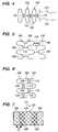
- FIG. 1is a partially cutaway side view of an intravascular medical device constructed in accordance with a preferred embodiment of the present inventions, wherein the medical device is particularly shown in a collapsed geometry;
- FIG. 2is a side view of the medical device of FIG. 1 , particularly shown in an expanded geometry;
- FIG. 3is a cross-sectional view of the medical device of FIG. 2 , taken along the line 3 — 3 ;
- FIG. 4is a side view of a modification of the medical device of FIG. 2 , particularly shown in an expanded geometry;
- FIG. 5is a close-up view of the medical device of FIG. 2 ;
- FIG. 6is a close-up view of another modification of the medical device of FIG. 2 , particularly shown in an expanded geometry
- FIG. 7is a side view of another alternative embodiment of the medical device of FIG. 2 ;
- FIG. 8is a close-up view of the medical device of FIG. 7 , taken along the lines 8 — 8 ;
- FIG. 9is a side view of a modification of the medical device of FIG. 7 ;
- FIG. 12is a cross-sectional view of another delivery catheter used in the delivery kit of FIG. 10 , taken along the line 12 — 12 ;
- FIG. 13is a close-up side view of the electrode body of the medical device of FIG. 1 , particularly showing the attachment of an electrolytic pusher wire used in the delivery kit of FIG. 10 ;
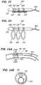
- FIG. 16is a perspective view of the medical device of FIG. 15 , particularly shown in an expanded geometry
- FIG. 18Ais a side view of the medical device of FIG. 15 expanded within a blood vessel;
- FIG. 18Bis a cross-sectional view of the medical device and blood vessel of FIG. 18A taken along the line 18 B— 18 B;
- FIG. 19is a perspective view of still another intravascular medical device constructed in accordance with a preferred embodiment of the present inventions, wherein the medical device is particularly shown in a collapsed geometry;
- FIG. 20is a perspective view of the medical device of FIG. 19 , particularly shown in an expanded geometry
- FIG. 21Ais a side view of the medical device of FIG. 19 expanded within a blood vessel;
- FIG. 21Bis a cross-sectional view of the medical device and blood vessel of FIG. 21A taken along the line 21 B— 21 B;
- FIG. 22is a perspective view of yet another intravascular medical device constructed in accordance with a preferred embodiment of the present inventions, wherein the medical device is particularly shown in a collapsed geometry;
- FIG. 23is a perspective view of the medical device of FIG. 22 , particularly shown in an expanded geometry
- FIG. 24Ais a side view of the medical device of FIG. 22 expanded within a blood vessel;
- FIG. 25is a perspective view of yet another intravascular medical device constructed in accordance with a preferred embodiment of the present inventions, wherein the medical device is particularly shown in a collapsed geometry;
- FIG. 26is a perspective view of the medical device of FIG. 25 , particularly shown in an expanded geometry
- FIG. 27Ais a side view of the medical device of FIG. 25 expanded within a blood vessel;
- FIG. 27Bis a cross-sectional view of the medical device and blood vessel of FIG. 27A taken along the line 271 B— 27 B;
- FIG. 28is a side view of another modification of the medical device of FIG. 2 , particularly shown in an expanded geometry;
- FIG. 29is a side view of still another modification of the medical device of FIG. 2 , particularly shown in an expanded geometry;
- FIG. 30is a side view of yet another modification of the medical device of FIG. 2 , particularly shown in an expanded geometry.
- the medical device 100comprises an expandable/collapsible tubular electrode body 102 , and a plurality of flexible conductive leads 104 electrically coupled to the electrode body 102 .
- the tubular bodycan either be continuous tubular structure or a structure that has a tubular profile, such as a coil.
- the electrode body 102can be transformed from a collapsed geometry ( FIG. 1 ) into an expanded geometry ( FIG. 2 ). In its collapsed geometry, the medical device 100 can be intravascularly delivered to a target site within a vessel using a standard stent delivery apparatus.
- a removable sheath or covering 103is disposed over the collapsed electrode body 102 .
- the sheath 103may have one or more delivery wires (not shown) that can be pulled in order to remove the sheath 103 from the electrode body 102 , thereby allowing the medical device 100 to be placed in its expanded geometry.
- the electrode body 102When the medical device 100 is in its expanded geometry, the electrode body 102 can be placed into firm contact with the target site and used to transmit to and/or receive electrical signals from the blood vessel and surrounding tissue, while minimizing blood occlusion.
- the leads 104the proximal ends of which will extend from the intravascular access point in the patient (e.g., the femoral vein or jugular vein), are configured to be coupled to an implanted or external source and/or recorder of the electrical signals (not shown), as will be described in further detail below.
- the electrode body 102comprises a plurality of electrically conductive sub-structures 106 (in this case, three), which together, form an integrated support structure.
- the conductive sub-structures 106are self-expanding (i.e., they automatically expand in the absence of a radially compressive force).
- the conductive sub-structures 106expand only in the presence of a radially expanding force, such with a stent balloon (not shown). In any event, once expanded, the rigidity of the conductive sub-structures 106 will allow them to remain in their expanded geometry until a radially compressive force is applied.
- the conductive sub-structures 106are distinct in that they are separately formed, and then they are linked together to form the integrated structure.
- the conductive sub-structures 106are cylindrical structures that are axially aligned along the length of the electrode body 102 .
- the conductive sub-structures 106act as three ring electrodes that extend along the electrode body 102 .
- each conductive support structure 106takes the form of semi-cylindrical structure that extends partially around the electrode body 102 .
- two semi-circular conductive sub-structures 106are linked together along the axis of the electrode body 102 to form an upper electrode and a lower electrode.
- the semi-cylindrical conductive sub-structures 106can be further divided to create additional electrodes.
- each conductive sub-structure 106is skeletal in nature, and is formed by fashioning a wire or wires into an undulating shape, as illustrated in FIGS. 2 and 4 .
- the wire or wirescan be fashioned into a mesh, braid, or coil to form the skeletal structure.
- each conductive sub-structure 106may not be skeletal in nature, but rather may be composed of a resilient continuous material.
- the diameter of the wire used to make each conductive sub-structure 106preferably has a diameter to provide a hoop strength to the conductive sub-structure 106 sufficient to hold the electrode body 102 in place within the selected blood vessel without moving as a result of the repetitive blood pulsing within the vascular system, but without distending the vessel wall.
- each conductive sub-structure 106is both biocompatible and electrically conductive.
- such materialis also radiopaque and allows for electrolytic detachable linkages to the proximal end of the electrode body 102 , as will be described in further detail below.
- Suitable metals and alloys for the composition of the support structureinclude Platinum Group metals, especially platinum, rhodium, palladium, rhenium, as well as tungsten, gold, silver, tantalum, and alloys of these metals, such as a platinum/tungsten alloy.
- Each conductive sub-structure 106can also be composed of a wide variety of stainless steels if some sacrifice of radiopacity can be tolerated.
- the wire used to form the conductive sub-structure 106can be further coated with platinum-iridium, gold, or silver to improve its conduction properties, biocompatibility, and radiopacity.
- Each conductive sub-structure 106can be coated with additives, such as a non-thrombogenic agent to prevent blood coating, or a therapeutic agent.
- the portions of the conductive sub-structures 106 that are mechanically linked togetherare electrically isolated from each other.
- a plurality of electrically insulative elements 110are connected between the loops 108 , thereby mechanically linking, while electrically isolating, the conductive sub-structures 106 , as illustrated in FIG. 5 .
- the insulative elements 110are shown in FIGS. 2 , 4 , and 6 as single strands of material, the insulative elements 110 can have other shapes and forms, e.g., a loop or a hook.
- the insulative elements 110can be composed of a suitably biocompatible and non-conductive material, such as silicone, nylon, Pebax®, polyimide, or urethane.
- the insulative elements 110can be discrete elements that are bonded to the loops 108 of the respective conductive sub-structures 106 using a suitable material, such as silicone, Pebax®, and urethane, or can be formed by, e.g., microinjecting a non-conductive material, such as silicone, Pebax®, or urethane, between the loops 108 .
- the insulative elements 100have sufficient axial rigidity to maintain the spatial separation between the sub-structures 106 to avoid electrical shorting.
- FIG. 28illustrates an alternative electrode body 302 that electrically isolates the conductive sub-structures 106 with insulative tubular elements 310 that circumferentially extend around the electrode body 302 .
- the tubular elements 310can be integrated into a single tubular member, in which case, the conductive sub-structure 106 can be bonded to the exterior surface of the tubular member, or may be embedded into the tubular member.
- the tubular elements 310may be formed between the respective conductive sub-structures 106 as discrete pieces, e.g., by injection molding insulative material between the sub-structures 106 .
- tubular elements 310are in contact with every portion of the conductive sub-structures 106 .
- another electrode body 402comprises tubular elements 410 that are only formed between the loops 108 of the respective sub-structures 106 .
- the substructures 106can be bonded to the tips of the loops 108 using suitable means, such as an adhesive or melting, or the tubular elements 410 can be micro-injected between the loops 108 .
- suitable meanssuch as an adhesive or melting
- the tubular elements 410can be micro-injected between the loops 108 .
- the tubular elements 310 and 410 illustrated in FIGS. 28 and 29primarily exist to provide electrical insulation to the sub-structures 106 , and do not significantly affect the radial spring force provided by the conductive sub-structures 106 .
- FIG. 30illustrates an alternative electrode body 502 that electrically isolates the conductive sub-structures 106 with a plurality of insulative elements 510 that connect the loops 108 of a pair of conductive sub-structures 106 in a zig-zag shape.
- the zig-zagged insulative elements 510can be made by, e.g., bonding or embedding the conductive sub-structures 106 onto or into an electrically insulative tubular member, similar to that shown in FIG. 28 , and then etching away the insulative material to form the insulative elements 510 .
- the loops 108 of the conductive sub-structures 106are directly linked together.
- insulative elements 110take the form of an insulative coating applied to one loop 108 of each connected loop pair, thereby electrically insulating the directly linked conductive sub-structures 106 from each other. It should be noted that directly linking the conductive sub-structures 106 in this manner facilitates the retrievability of the electrode body 102 . That is, since the loops 108 are tightly fitted together, snagging of the loops 108 as the electrode body 102 is pulled into a sheath is minimized.
- the electrode body 102can optionally have a layer of insulative material 111 , such as elastic or silicone, disposed on the inner surface of the conductive sub-structures 106 .
- a layer of insulative material 111such as elastic or silicone
- the leads 104are connected to the electrode body 102 using suitable means, such as welding or soldering.
- Each lead 104comprises an electrically conductive core with an outer insulative layer.
- the length of the lead 104is preferably sized to extend from intravascular access point in the patient to the selected target site within the blood vessel where the electrode body 102 will be implanted. If the medical device 100 is to be connected to the implanted stimulator or recorder, the length of the lead 104 should be sized to extend from the implantation site of the stimulator and/or recorder to the selected target site when routed through the intravascular access point.
- the length of the lead 104may be in the range of 50 cm to 100 cm. If, however, the target site is in the patient's brain, the implantation site of the source or recorder is in the abdominal region of the patient, and the intravascular access point is the patient's femoral vein, then the length of the lead 104 may be in the range of 150 cm to 300 cm.
- the leads 104can be coupled to the electrode body 102 in a variety of manners to achieve different electrode functionalities.
- the leads 104are coupled to the respective conductive sub-structures 106 , so that the conductive sub-structures 106 are completely electrically isolated from one another.
- the electrode body 102can have a multiple-channel and/or multi-polar capability. That is, if operating as a multi-channel device, the conductive sub-structures 106 can simultaneously receive multiple signals (if connected to a recorder) or can simultaneously transmit multiple signals (if connected to a stimulation source).
- electrical signalscan be transmitted between one or more conductive sub-structures 106 (as anodes) and one or more other conductive sub-structures (as cathodes).
- the conductive sub-structures 106can be electrically combined to make a single-channel and/or monopolar device if the proximal ends of the leads 104 are electrically connected together at the stimulator and/or recorder.
- a single lead 104can be coupled to one of the conductive sub-structures 106 , preferably the proximal-most conductive sub-structure 106 , in which case, the conductive sub-structures 106 can be electrically coupled together in series, e.g., by directly or indirectly electrically coupling a pair of respective loops 108 together.
- electrode body 102may alternatively have a wireless transmitter and/or receiver in order to provide the electrode body 102 with the capability of wirelessly communicating with a remote stimulator and/or recorder.
- the leadswill be routed from the electrodes on the electrode body 102 to the transmitter and/or receiver.
- FIG. 7illustrates an electrode body 122 that forms cylindrically-shaped electrically conductive regions 126 (delineated by the dashed line) extending around the electrode body 122 , and electrically insulative regions 128 extending around the electrode body 102 between the conductive regions 126 .
- the unibody support structure 124is skeletal in nature and, in this case, is formed as a tubular mesh.
- the wires used to form the unibody support structure 124comprises an electrically conductive core 130 and an insulative layer 132 disposed over the conductive core 130 , as best shown in FIG. 8 .
- the conductive regions 126are formed by removing the insulative layer 132 from portions of the support structure 124 (in this case, cylindrical portions) in order to expose the underlying conductive core 130 . Removal of the insulative layer 132 can be accomplished in any suitable manner, including mechanical, chemical, or laser etching.
- the exposed portions of the support structure 124serve as the conductive regions 128
- the unexposed portions of the support structure 124serve as the insulative regions 128 .
- the electrically conductive leads 104can be coupled to the electrode body 102 in the same manner described above, with the exception that the leads 104 are coupled to the conductive core 130 of the support structure 132 .
- the conductive and insulative regions 126 / 128 of the electrode body 102can be formed into other shapes besides cylindrical shapes.
- the conductive regions 126are formed as rectangular patches that are disposed about the electrode body 102 .
- the kit 150comprises the previously described medical device 100 , a delivery catheter 152 configured for intravascularly delivering the medical device 100 into selected blood vessels within the patient's body, a guidewire 154 configured for guiding the delivery catheter 152 into the selected blood vessels, and a detachable pusher element 156 configured for deploying the medical device 100 from the delivery catheter 152 into a selected region within a blood vessel.
- the pusher element 156is mechanically coupled to the electrode body 102 , and is axially rigid, so that the electrode body 102 can be introduced through the catheter 152 , yet laterally flexible to allow the pusher element 156 to bend around the natural curves within the patient's vasculature.
- the pusher element 156can be selectively detached from the electrode body 102 (once properly placed) using an electrolytic arrangement.
- the pusher element 156comprises an electrically conductive core wire 158 composed of a material that will electrolytically dissolve in an aqueous fluid medium, such as blood, saline solution, or other bodily fluid.
- aqueous fluid mediumsuch as blood, saline solution, or other bodily fluid.
- Materials that are capable of electrolytically dissolvingare steel, stainless steel, nickel, and nickel/titanium alloys.
- the electrode body 102may be suitably coupled to the distal end of the core wire 158 using means, such as crimping, soldering, or welding.
- the pusher element 156further comprises an insulative sleeve 160 that, with the exception of a small sacrificial portion 162 just proximal to the mounted electrode body 102 , covers the core wire 158 .
- the length of the sacrificial portion 162is preferably small. For instance, it may be as short as 0.010 inches, and typically no longer than 0.150 inches in length.
- the insulative sleeve 160is composed of a material that will not decompose prior to the sacrificial portion 162 of the core wire 158 .
- the insulative sleeve 160may be composed of polytetrafluoroethylene, fluoropolymers, polyurethane, parylene, polyethylene, polypropylene, polyethylene terephthalate, or other known suitable, typically polymeric, material.
- pusher wires with mechanical detachment mechanismscan be used to selectively detach the electrode body 102 .
- U.S. Pat. Nos. 5,234,437, 5,250,071, 5,261,916, 5,304,195, 5,312,415, and 5,350,397which are expressly incorporated herein by reference, disclose such mechanically detachable means.
- the delivery catheter 152comprises an elongate, flexible, catheter body 164 , and a delivery lumen 166 (shown in FIG. 11 ) extending the length of the catheter body 164 .
- the delivery lumen 166is sized to alternately receive a guidewire 154 and the medical device 100 .
- the delivery catheter 152further comprises a proximal adapter 168 suitably mounted on the proximal end of the catheter body 164 .
- the proximal adapter 168comprises a port 170 out which the guidewire 154 and medical device 100 .
- dedicated guidewire and electrode lead lumens, along with respective ports,can be provided.
- the catheter body 164is composed of a medically acceptable material, preferably a nondistensible polymer having the appropriate mechanical properties.
- Preferred materialsinclude polyethylene, polyester, polypropylene, polyimide, polyvinyl chloride, ethylvinyl acetate, polyethylene terephthalate, polyurethane, Pebax®, fluoropolymers, silicone, and their mixtures and block or random copolymers.
- the catheter body 164preferably has a relatively stiff proximal segment, which makes up between 70%–95% of the total length of the catheter body 164 , and a relatively flexible distal segment, which makes up the remaining 5%–30% of the length of the catheter body 164 .
- the delivery lumen 166 of the catheter 152preferably has a diameter of between 2–50 mils, but ultimately will be sized to allow the guidewire 154 and medical device 100 to be respectively introduced therethrough.
- the catheter 152may comprises separate lumens 168 and 170 for respectively receiving the guidewire 154 and medical device 100 .
- the outer diameter of the catheter body 164is preferably between 8–80 mils, but ultimately will be sized such that blood flow is not occluded within the smallest blood vessel through which the delivery catheter 152 will be introduced.
- the vessel sitemay be within a small diameter vessel having a 2–5 mm diameter and accessible by way of a tortuous vessel path, which may involve sharp vessel turns and multiple vessel branches.
- the catheter 152preferably has a small, flexible construction with a diameter of less than 40 mil, and preferably between 8–30 mils.
- the length of the catheter body 164will typically be from 50–300 cm, depending on the total linear length of the blood vessels that the delivery catheter 152 must traverse from its entry point into the patient's vasculature to the target delivery site of the electrode body 102 .
- the guidewire 154may have any suitable construction for guiding the delivery catheter 152 to its intended site in the brain.
- the length of the guidewire 154is at least about 10–50 cm longer than the length of the catheter 152 , such that the distal end of the guidewire 154 can be extended several centimeters or more beyond the distal end of the delivery catheter 152 , while allowing the proximal end of the guidewire 154 to be manipulated, such as by torqueing.
- the proximal end of the guidewire 154is equipped with a handle 155 for applying torque to the wire during catheter operation.
- the guidewire 154may optionally include radiopaque bands (not shown) for visualization under fluoroscopy. Additional details regarding the structure and dimensions of guidewires suitable for guiding catheters into the vasculature of the brain are disclosed in U.S. Pat. No. 6,074,507, which is expressly incorporated herein by reference.
- the kit illustrated in FIG. 10is not the only manner in which the medical device 100 can be delivered to a vessel target site, but rather there are other means of delivering the medical device 100 into a vessel.
- the medical device 100can be delivered within a vessel by mounting the electrode body 102 around the distal end of a catheter, as disclosed in U.S. Pat. Nos. 5,534,007 and 6,562,063, which are expressly incorporated herein by reference.
- the guidewire 154is routed into a selected blood vessel 180 until the distal end of the guidewire 154 extends past a target site 182 ( FIG. 14A ).
- diagnostic imagingsuch as fluoroscopy, magnetic resonance imaging (MRI), and computer tomography (CT) is preferably used to track the distal end of the guidewire 154 .
- the access site into the vasculaturewill ultimately depend on the selected implantation site of the stimulation and/or recording device. For example, if the stimulation/recording device is to be implanted within the chest or clavical region, or behind the ear, of the patient, the jugular vein should be selected as the access point. If, on the other hand, the stimulation/recording device is to be implanted within the abdominal or groin region of the patient, the femoral vein should be selected as the access point.
- the delivery catheter 152is introduced over the guidewire 154 until the distal end of the catheter 152 is just proximal to the target site 182 ( FIG. 14B ).
- the guidewire 154is removed from the delivery lumen 166 via the proximal adapter 168 of the delivery catheter 152 , and the medical device 100 and associated pusher element 156 are inserted into the delivery catheter 152 via the proximal adapter 168 , and then distally advanced through the delivery catheter 152 until the collapsed electrode body 102 deploys out from the distal end of the catheter 152 adjacent the target site 182 ( FIG. 14C ).
- the device 100may resemble an “on a wire” type device (e.g., a guidewire or soft tip design is integrated into the device 100 ), in which case the device 100 is advanced to the target site 182 under its own influence.
- the sheath 103is removed from the electrode body 102 , which then expands into firm contact with the inside of the blood vessel 180 ( FIG. 14D ).
- the pusher element 156is then electrolytically detached from the electrode body 102 and removed from the delivery catheter 152 via the proximal adapter 168 ( FIG. 14E ).
- detachment of the pusher element 156can be accomplished by applying an electrical current to the proximal end of the core wire 158 , which as previously described above, causes the sacrificial joint 162 (shown in FIG. 13 ) on the core wire 158 to dissolve in the presence of blood. If desired, additional medical devices 100 can be placed within the same or different blood vessel in a similar manner.
- the delivery catheter 152is removed from the patient's body.
- the medical device 100may be left within the patient either acutely (i.e., only during an operation and then removed after the operation has been completed), chronically, or sub-chronically (i.e., less than six months).
- the proximal ends of the leads 104 of the medical device 100will remain outside of the patient's body after the deployment process is completed, and in particular, will extend from the vascular access point, e.g., the internal jugular vein or femoral vein.
- the exposed ends of the leads 104can be subcutaneously routed a short distance to the clavical or chest region or behind the ear of the patient (in this case where the jugular vein is the access point) or the abdominal or groin region of the patient (in the case where the femoral vein is the access point), where they can be coupled to the implanted stimulation/recording device.
- the stimulation/recording device 100may not be implanted, but rather located exterior to the patient, e.g., during a non-chronic procedure.
- the medical device 200comprises an expandable/collapsible electrode body 202 , and a plurality of flexible conductive leads 204 electrically coupled to the electrode body 202 .
- the electrode body 202can be transformed from a collapsed geometry ( FIGS. 15 and 17 ) into an expanded geometry ( FIG. 16 ).
- the electrode body 202can be intravascularly delivered to a target site within a vessel using a standard stent delivery apparatus.
- a removable sheath or covering 203is disposed over the collapsed electrode body 202 , as shown in FIG. 15 .
- the sheath 203may have one or more delivery wires (not shown) that can be pulled in order to remove the sheath 203 from the electrode body 202 , thereby allowing the electrode body 202 to be placed in its expanded geometry, as shown in FIG. 16 .
- the electrode body 202In its expanded geometry, the electrode body 202 can be placed into firm contact with the target site and used to transmit electrical signals to and/or receive electrical signals from the blood vessel and surrounding tissue, while minimizing blood occlusion.
- the electrode body 202comprises an arcuate resilient spring 206 and a plurality of electrodes 208 (in this case, three) disposed on the spring 206 .
- the resilient spring 202is non-tubular, i.e., its arcuate shape spans less than 360 degrees. In this manner, unlike tubular electrode structures, the electrode body 202 is more adaptable to variously sized blood vessels. In addition, the transmitted and/or recorded electrical energy is more focused.
- the arcuate shape of the arcuate spring 206spans greater than 180 degrees, so that it is capable of being frictionally adhered to the inner surface of a blood vessel.
- the spring 206is pre-shaped to assume its arcuate shape in the absence of an external force, but can be collapsed, e.g., by rolling the spring 206 .
- the electrode body 202can be placed and maintained in its collapsed geometry by applying a compressive force on the spring 206 and placing it within the sheath 203 .
- the electrode body 202can be placed in its expanded geometry by releasing the compressive force to unfurl the spring 206 , which naturally occurs when the sheath 203 is removed.
- the resiliency of the spring 206continuously urges it against the inner surface of the blood vessel with a force sufficient to hold the electrode body 202 in place within the selected blood vessel without moving as a result of the repetitive blood pulsing within the vascular system, but without distending the vessel wall.
- the spring 206is non-porous, but can alternatively be skeletal in nature, such as a coil, mesh, or braid.
- the surface of the arcuate spring 206is preferably both biocompatible and electrically insulative.
- the arcuate spring 206can be entirely composed of a resilient insulative material, such as polyimide, polytetrafluoroethylene (PTFE), Fluorinated Ethylene Propylene (FEP), polyethylene, or silicone, or can be composed of a core of electrically conductive material, such as one or more of the various materials from which the previously described conductive sub-structures 106 are composed, and an insulative layer disposed over the core.
- a resilient insulative materialsuch as polyimide, polytetrafluoroethylene (PTFE), Fluorinated Ethylene Propylene (FEP), polyethylene, or silicone
- PTFEpolytetrafluoroethylene
- FEPFluorinated Ethylene Propylene
- siliconeor can be composed of a core of electrically conductive material, such as one or more of the various materials from which the previously described conductive sub-structures 106 are composed, and an insulative layer disposed over the core.
- the electrodes 208are applied to the spring 206 as a layer of highly electrically conductive and biocompatible material, such as gold, silver, or platinum.
- Deposition techniquesinclude sputtering, vapor deposition, ion beam deposition, electroplating over a deposited seed layer, or a combination of these processes.
- the electrodes 208may be discrete and flexible elements, such as mesh or braid, that is suitably bonded to the spring 206 .
- the spring 206itself, may form the electrodes 208 .
- any of the previously described techniquessuch as forming electrodes from electrically conductive sub-structures, or removing insulative material to expose portions of an electrically conductive core, can be used.
- the leads 204are configured to be coupled to an implanted or external source and/or recorder of the electrical signals (not shown), as will be described in further detail below.
- the conductive leads 204which are of similar construction and length as leads 104 , are suitably coupled to the electrodes 208 using means, such as welding or soldering.
- the medical device 200can be delivered to a target site 182 within a selected blood vessel in the same manner as that described above, so that the electrode body 202 is expanded into firm contact with the blood vessel 180 , as illustrated in FIGS. 18A and 18B .
- the medical device 210comprises an expandable/collapsible electrode body 212 and a plurality of flexible conductive leads 214 electrically coupled to the electrode body 212 .
- the electrode body 212can be transformed from a collapsed geometry ( FIG. 19 ) into an expanded geometry ( FIG. 20 ). In its collapsed geometry, the electrode body 212 can be intravascularly delivered to a target site within a vessel using a standard stent delivery apparatus. In its expanded geometry, the electrode body 212 can be placed into firm contact with the target site and used to transmit electrical signals to and/or receive electrical signals from the blood vessel and surrounding tissue, while minimizing blood occlusion.
- the electrode body 212comprises an arcuate structure 216 , a plurality of electrodes 218 (in this case, three) disposed on the structure 216 , and a plurality of resilient spring loops 215 mounted to the arcuate structure 216 .
- the spring loops 215can be mounted to the arcuate structure 216 in any suitable manner, including welding or soldering.
- the spring loops 215are pre-shaped to extend laterally from the arcuate structure 216 in the absence of a compressive force, but can be collapsed, e.g., by applying a compressive force to the spring loops 215 .
- the electrode body 212can be placed in its collapsed geometry by applying a compressive force to hinge the spring loops 215 , which naturally occurs when the electrode body 212 is introduced within the delivery catheter 152 .
- the electrode body 212can be placed in its expanded geometry by releasing the compressive force in order to hinge the spring loops 215 into their laterally extending position, which naturally occurs when the electrode body 212 exits the delivery catheter 152 .
- the resiliency of the spring loops 215continuously urges the arcuate structure 216 against the opposing vessel wall into firm contact with the target site with a force sufficient to hold the electrode body 212 in place within the selected blood vessel without moving as a result of the repetitive blood pulsing within the vascular system, but without distending the vessel wall.
- the arcuate structure 216is non-tubular, i.e., its arcuate shape spans less than 360 degrees, thereby providing the electrode body 212 with the same advantages as the electrode body 202 .
- the electrode body 212can advantageously span less than 180 degrees, since the electrode body 212 need not have the capability, by itself, to adhere to the vessel walls. That is, the force applied by the spring loops 215 is sufficient to place the electrode body 212 firmly against the vessel wall. In this manner, the electrode body 212 may be even more adaptable to a variety of blood vessel shapes, and the electrical stimulation and/or recording energy more focused, than that of the previously described arcuate electrode body 202 .
- the surface of the arcuate structure 216is preferably both biocompatible and electrically insulative, and thus can be constructed in a similar manner as the spring 206 , with the exception that the arcuate structure 216 need not be resilient.
- the arcuate structure 216may be composed of a resilient material, so that it acts as a spring much like the resilient spring 206 of the electrode body 202 . In this manner, the frictional engagement created by the resiliency of the spring, in addition to the lateral forces created by the resiliency of the spring loops 215 , will place the electrodes 218 firmly in contact with the vessel wall.
- the electrodes 218can be composed of the same material and be disposed on the arcuate structure 216 in the same manner as the previously described electrodes 208 .
- the resilient spring loops 215can be composed of an electrically conductive material, so that they can also serve as electrodes. In this case, the spring loops 215 can be directly mounted to the electrodes 218 . Alternatively, the spring loops 215 can act as electrodes, obviating the need for separate electrodes 218 on the arcuate structure 216 .
- the conductive leads 214are configured to be coupled to an implanted or external source and/or recorder of the electrical signals (not shown), as will be described in further detail below.
- the conductive leads 214which are of similar construction and length as leads 104 , are suitably coupled to the electrodes 218 using means, such as welding or soldering.
- the medical device 210can be delivered to a target site 182 within a selected blood vessel in the same manner as that described above, so that the electrode body 212 is placed into firm contact with the blood vessel 180 , as illustrated in FIGS. 21A and 21B .
- the medical device 220comprises an expandable/collapsible electrode body 222 and a plurality of flexible conductive leads 224 electrically coupled to the electrode body 222 .
- the electrode body 222can be transformed from a collapsed geometry ( FIG. 22 ) into an expanded geometry ( FIG. 23 ). In its collapsed geometry, the electrode body 222 can be intravascularly delivered to a target site within a vessel using a standard stent delivery apparatus. In its expanded geometry, the electrode body 222 can be placed into firm contact with the target site and used to transmit electrical signals to and/or receive electrical signals from the blood vessel and surrounding tissue, while minimizing blood occlusion.
- the electrode body 222comprises an elongated cylindrical member 226 , a plurality of electrodes 228 (in this case, three) disposed on the cylindrical member 226 , and a plurality of resilient spring loops 225 mounted to the cylindrical member 226 .
- the spring loops 225can be mounted to the cylindrical member 226 in any suitable manner, including welding, soldering, or tying the spring loops 225 to the cylindrical member 226 .
- the spring loops 225are pre-shaped to extend laterally from the cylindrical member 226 in the absence of a compressive force, but can be collapsed, e.g., by applying a compressive force to the spring loops 225 .
- the resiliency of the spring loops 225continuously urges the cylindrical member 226 against the opposing vessel wall into firm contact with the target site with a force sufficient to hold the electrode body 222 in place within the selected blood vessel without moving as a result of the repetitive blood pulsing within the vascular system, but without distending the vessel wall.
- the cylindrical member 226can be composed of any flexible and insulative material, such as Pebax®, nylon, silicone, or urethane.
- the electrodes 228take the form of a ring electrodes that axially extend along the member 226 .
- the electrodes 228may be discrete elements that are mounted to the cylindrical member 226 in an interference relationship, or may be suitably formed on the cylindrical member 226 as a layer of material.
- the electrodes 228may be composed of the same material as the previously described electrodes 208 .
- the resilient spring loops 225can also be composed of an electrically conductive material in order to serve as electrodes, in which case, the spring loops 225 can be directly mounted to the electrodes 228 , or alternatively, the spring loops 225 can act as electrodes, obviating the need for separate electrodes 228 on the cylindrical member 226 .
- the conductive leads 224are configured to be coupled to an implanted or external source and/or recorder of the electrical signals (not shown), as will be described in further detail below.
- the conductive leads 224which are of similar construction and length as leads 104 , extend through the cylindrical member 226 where they are suitably coupled to the electrodes 228 using means, such as welding or soldering.
- the medical device 220can be delivered to a target site 182 within a selected blood vessel in the same manner as that described above, so that the electrode body 222 is placed into firm contact with the blood vessel 180 , as illustrated in FIGS. 24A and 24B .
- the medical device 230comprises an expandable/collapsible electrode body 232 and a plurality of flexible conductive leads 234 electrically coupled to the electrode body 232 .
- the electrode body 232can be transformed from a collapsed geometry ( FIG. 25 ) into an expanded geometry ( FIG. 26 ). In its collapsed geometry, the electrode body 232 can be intravascularly delivered to a target site within a vessel using a standard stent delivery apparatus. In its expanded geometry, the electrode body 232 can be placed into firm contact with the target site and used to transmit electrical signals to and/or receive electrical signals from the blood vessel and surrounding tissue, while minimizing blood occlusion.
- the electrode body 232comprises a central support member 236 , a pair of resilient spring arms 235 extending from the distal end of the support member 234 , and a pair of electrodes 238 disposed on the distal ends of the respective spring arms 235 .
- the support member 236can be composed of any suitable rigid or semi-rigid insulative material, such as Pebax®, nylon, urethane, silicone, or polyimide.
- the spring arms 235can be mounted to the support member 236 in any suitable manner, including welding or soldering.
- the spring arms 235are pre-shaped to laterally extend away from each other in the absence of a compressive force to place the electrode body 232 , but can be collapsed, e.g., by applying a compressive force to the spring arms 235 .
- the electrode body 232can be placed and maintained in its collapsed geometry by applying a compressive force to move the spring arms 235 towards each other, which naturally occurs when the electrode body 232 is introduced within the delivery catheter 152 .
- a sheath(not shown) can be optionally used to maintain the electrode body 232 in its collapsed geometry as it is introduced through the delivery catheter 152 .
- the electrode body 232can be placed in its expanded geometry by releasing the compressive force to allow the spring arms 235 to move away from each other, which naturally occurs when the electrode body 232 exits the delivery catheter 152 .
- the spring arms 235expand against the vessel wall, they will create an anchoring force sufficient to hold the electrode body 232 in place within the selected blood vessel without moving as a result of the repetitive blood pulsing within the vascular system, but without distending the vessel wall.
- the electrodes 238are discrete elements that are suitably bonded onto the resilient arms 235 , although the electrodes 238 can be formed onto the spring arms 235 in other suitable manners. With the exception of their distal ends, the spring arms 235 are preferably coated with an electrically insulative material. Alternatively, the exposed distal ends of the spring arms 235 can act as electrodes, thereby obviating the need to bond separate discrete electrodes 238 onto the spring arms 235 .
- the conductive leads 234are configured to be coupled to an implanted or external source and/or recorder of the electrical signals (not shown), as will be described in further detail below.
- the conductive leads 234which are of similar construction and length as leads 104 , extend through the support member 236 and are suitably coupled to the proximal ends of the spring arms 235 using means, such as welding or soldering.
- the medical device 230can be delivered to a target site 182 within a selected blood vessel in the same manner as that described above, so that the electrode body 232 is placed into firm contact with the blood vessel 180 , as illustrated in FIGS. 27A and 27B .
Landscapes
- Health & Medical Sciences (AREA)
- Cardiology (AREA)
- Heart & Thoracic Surgery (AREA)
- Life Sciences & Earth Sciences (AREA)
- Engineering & Computer Science (AREA)
- Biomedical Technology (AREA)
- Nuclear Medicine, Radiotherapy & Molecular Imaging (AREA)
- Radiology & Medical Imaging (AREA)
- Vascular Medicine (AREA)
- Animal Behavior & Ethology (AREA)
- General Health & Medical Sciences (AREA)
- Public Health (AREA)
- Veterinary Medicine (AREA)
- Electrotherapy Devices (AREA)
- Surgical Instruments (AREA)
- Media Introduction/Drainage Providing Device (AREA)
Abstract
Description
Claims (34)
Priority Applications (10)
| Application Number | Priority Date | Filing Date | Title |
|---|---|---|---|
| US10/841,070US7231260B2 (en) | 2004-05-06 | 2004-05-06 | Intravascular self-anchoring electrode body with arcuate springs, spring loops, or arms |
| US10/841,069US8412348B2 (en) | 2004-05-06 | 2004-05-06 | Intravascular self-anchoring integrated tubular electrode body |
| ES05733553TES2315862T3 (en) | 2004-05-06 | 2005-03-25 | INTRAVASCULAR SELF-LINK ELECTRODE BODY. |
| EP05733553AEP1742702B1 (en) | 2004-05-06 | 2005-03-25 | Intravascular self-anchoring electrode body |
| AT05733553TATE415183T1 (en) | 2004-05-06 | 2005-03-25 | INTRAVASCULAR SELF-ANCHORING ELECTRODE BODY |
| DE602005011269TDE602005011269D1 (en) | 2004-05-06 | 2005-03-25 | INTRAVASCULARLY SELF-ANCHORED ELECTRODE BODY |
| EP08017295AEP2016973A1 (en) | 2004-05-06 | 2005-03-25 | Intravascular self-anchoring electrode body |
| PCT/US2005/010121WO2005110528A1 (en) | 2004-05-06 | 2005-03-25 | Intravascular self-anchoring electrode body |
| JP2007511365AJP2007535984A (en) | 2004-05-06 | 2005-03-25 | Intravascular self-contained electrode body |
| CA002565265ACA2565265A1 (en) | 2004-05-06 | 2005-03-25 | Intravascular self-anchoring electrode body |
Applications Claiming Priority (2)
| Application Number | Priority Date | Filing Date | Title |
|---|---|---|---|
| US10/841,070US7231260B2 (en) | 2004-05-06 | 2004-05-06 | Intravascular self-anchoring electrode body with arcuate springs, spring loops, or arms |
| US10/841,069US8412348B2 (en) | 2004-05-06 | 2004-05-06 | Intravascular self-anchoring integrated tubular electrode body |
Publications (2)
| Publication Number | Publication Date |
|---|---|
| US20050251239A1 US20050251239A1 (en) | 2005-11-10 |
| US7231260B2true US7231260B2 (en) | 2007-06-12 |
Family
ID=34964169
Family Applications (2)
| Application Number | Title | Priority Date | Filing Date |
|---|---|---|---|
| US10/841,069Expired - Fee RelatedUS8412348B2 (en) | 2004-05-06 | 2004-05-06 | Intravascular self-anchoring integrated tubular electrode body |
| US10/841,070Expired - Fee RelatedUS7231260B2 (en) | 2004-05-06 | 2004-05-06 | Intravascular self-anchoring electrode body with arcuate springs, spring loops, or arms |
Family Applications Before (1)
| Application Number | Title | Priority Date | Filing Date |
|---|---|---|---|
| US10/841,069Expired - Fee RelatedUS8412348B2 (en) | 2004-05-06 | 2004-05-06 | Intravascular self-anchoring integrated tubular electrode body |
Country Status (8)
| Country | Link |
|---|---|
| US (2) | US8412348B2 (en) |
| EP (2) | EP1742702B1 (en) |
| JP (1) | JP2007535984A (en) |
| AT (1) | ATE415183T1 (en) |
| CA (1) | CA2565265A1 (en) |
| DE (1) | DE602005011269D1 (en) |
| ES (1) | ES2315862T3 (en) |
| WO (1) | WO2005110528A1 (en) |
Cited By (85)
| Publication number | Priority date | Publication date | Assignee | Title |
|---|---|---|---|---|
| US20060259110A1 (en)* | 2004-03-12 | 2006-11-16 | Boston Scientific Scimed, Inc. | Collapsible/Expandable Tubular Electrode Leads |
| US20070010862A1 (en)* | 2005-04-26 | 2007-01-11 | Thomas Osypka | Apparatus and method for providing an electrical field to a targeted area |
| US20070135882A1 (en)* | 2005-12-09 | 2007-06-14 | Drasler William J | Cardiac stimulation system |
| US20070255379A1 (en)* | 2003-06-04 | 2007-11-01 | Williams Michael S | Intravascular device for neuromodulation |
| US20070288077A1 (en)* | 2006-06-07 | 2007-12-13 | Cherik Bulkes | Self-anchoring electrical lead with multiple electrodes |
| US20070293925A1 (en)* | 2006-06-15 | 2007-12-20 | Cardiac Pacemakers, Inc. | Biasing and fixation features on leads |
| US20080109054A1 (en)* | 2004-10-20 | 2008-05-08 | Scimed Life Systems, Inc. | Leadless Cardiac Stimulation Systems |
| US20090036939A1 (en)* | 2007-08-02 | 2009-02-05 | Udai Singh | Inductive element for intravascular implantable devices |
| US20090171411A1 (en)* | 2006-12-06 | 2009-07-02 | The Cleveland Clinic Foundation | Method and System for Treating Acute Heart Failure by Neuromodulation |
| US20090319012A1 (en)* | 2004-03-12 | 2009-12-24 | Boston Scientific Neuromodulation Corporation | Modular stimulation lead network |
| US7647109B2 (en) | 2004-10-20 | 2010-01-12 | Boston Scientific Scimed, Inc. | Leadless cardiac stimulation systems |
| US20100023088A1 (en)* | 2008-03-27 | 2010-01-28 | Stack Richard S | System and method for transvascularly stimulating contents of the carotid sheath |
| US20100114271A1 (en)* | 2008-10-31 | 2010-05-06 | Medtronic, Inc. | Shielded conductor filar - stimulation leads |
| US20100326701A1 (en)* | 2009-06-29 | 2010-12-30 | Boston Scientific Neuromodulation Corporation | Systems and methods for removing insulation disposed over conductors of implantable electric stimulation systems |
| US7937161B2 (en) | 2006-03-31 | 2011-05-03 | Boston Scientific Scimed, Inc. | Cardiac stimulation electrodes, delivery devices, and implantation configurations |
| US8050773B2 (en) | 2008-09-28 | 2011-11-01 | Jie Zhu | Expandable neuromodular stimulation lead |
| US8050774B2 (en) | 2005-12-22 | 2011-11-01 | Boston Scientific Scimed, Inc. | Electrode apparatus, systems and methods |
| US20120089153A1 (en)* | 2009-03-31 | 2012-04-12 | Inspire Medical Systems, Inc. | Percutaneous access for systems and methods of treating sleep apnea |
| US8185213B2 (en) | 2006-07-21 | 2012-05-22 | Boston Scientific Scimed, Inc. | Delivery of cardiac stimulation devices |
| US8204605B2 (en) | 2008-02-07 | 2012-06-19 | Cardiac Pacemakers, Inc. | Multi-site atrial electrostimulation |
| US8290600B2 (en) | 2006-07-21 | 2012-10-16 | Boston Scientific Scimed, Inc. | Electrical stimulation of body tissue using interconnected electrode assemblies |
| US8332036B2 (en) | 2004-10-20 | 2012-12-11 | Boston Scientific Scimed, Inc. | Leadless cardiac stimulation systems |
| US8332043B1 (en)* | 2007-02-06 | 2012-12-11 | Boston Scientific Neuromodulation Corporation | Self anchoring lead |
| US8398672B2 (en) | 2003-11-12 | 2013-03-19 | Nitinol Devices And Components, Inc. | Method for anchoring a medical device |
| US20130226272A1 (en)* | 2010-08-26 | 2013-08-29 | Acandis Gmbh & Co. Kg | Electrode for medical applications, system having an electrode, and method for producing an electrode |
| US8571662B2 (en) | 2007-01-29 | 2013-10-29 | Simon Fraser University | Transvascular nerve stimulation apparatus and methods |
| US8644934B2 (en) | 2006-09-13 | 2014-02-04 | Boston Scientific Scimed Inc. | Cardiac stimulation using leadless electrode assemblies |
| US9017323B2 (en) | 2010-11-16 | 2015-04-28 | Tva Medical, Inc. | Devices and methods for forming a fistula |
| US9025598B1 (en) | 2012-03-22 | 2015-05-05 | Nuax, Inc. | Cable/guidewire/interconnects communication apparatus and methods |
| US9067071B2 (en) | 2011-07-11 | 2015-06-30 | Interventional Autonomics Corporation | System and method for neuromodulation |
| US9126048B2 (en) | 2011-04-28 | 2015-09-08 | Interventional Autonomics Corporation | Neuromodulation systems and methods for treating acute heart failure syndromes |
| US9193313B2 (en) | 2012-03-22 | 2015-11-24 | Nuax, Inc. | Methods and apparatuses involving flexible cable/guidewire/interconnects |
| US9242100B2 (en) | 2012-08-07 | 2016-01-26 | Nuax, Inc. | Optical fiber-fine wire lead for electrostimulation and sensing |
| US9358140B1 (en) | 2009-11-18 | 2016-06-07 | Aneuclose Llc | Stent with outer member to embolize an aneurysm |
| US9446240B2 (en) | 2011-07-11 | 2016-09-20 | Interventional Autonomics Corporation | System and method for neuromodulation |
| US9478327B2 (en) | 2008-05-28 | 2016-10-25 | Nuax, Inc. | Durable fine wire electrical conductor suitable for extreme environment applications |
| US9486276B2 (en) | 2012-10-11 | 2016-11-08 | Tva Medical, Inc. | Devices and methods for fistula formation |
| US9513443B2 (en) | 2008-05-28 | 2016-12-06 | John Lawrence Erb | Optical fiber-fine wire conductor and connectors |
| US20170036011A1 (en)* | 2010-10-27 | 2017-02-09 | Dignity Health | Uterine electrical stimulation system and method |
| US9649211B2 (en) | 2009-11-04 | 2017-05-16 | Confluent Medical Technologies, Inc. | Alternating circumferential bridge stent design and methods for use thereof |
| US20170164464A1 (en)* | 2015-12-08 | 2017-06-08 | Kardium Inc. | Circuits for flexible structures |
| US9844663B2 (en) | 2010-09-28 | 2017-12-19 | The Board Of Trustees Of The Leland Stanford Junior University | Device and method for positioning an electrode in tissue |
| US9872981B2 (en) | 2010-09-28 | 2018-01-23 | Biotrace Medical, Inc. | Device and method for positioning an electrode in a body cavity |
| US9884182B2 (en) | 2011-07-11 | 2018-02-06 | Interventional Autonomics Corporation | Catheter system for acute neuromodulation |
| US9907684B2 (en) | 2013-05-08 | 2018-03-06 | Aneuclose Llc | Method of radially-asymmetric stent expansion |
| US10028747B2 (en) | 2008-05-01 | 2018-07-24 | Aneuclose Llc | Coils with a series of proximally-and-distally-connected loops for occluding a cerebral aneurysm |
| US10039920B1 (en) | 2017-08-02 | 2018-08-07 | Lungpacer Medical, Inc. | Systems and methods for intravascular catheter positioning and/or nerve stimulation |
| US10092427B2 (en) | 2009-11-04 | 2018-10-09 | Confluent Medical Technologies, Inc. | Alternating circumferential bridge stent design and methods for use thereof |
| US10172549B2 (en) | 2016-03-09 | 2019-01-08 | CARDIONOMIC, Inc. | Methods of facilitating positioning of electrodes |
| WO2019020986A1 (en) | 2017-07-28 | 2019-01-31 | Galvani Bioelectronics Limited | Electrode devices for neurostimulation |
| WO2019020983A1 (en) | 2017-07-28 | 2019-01-31 | Galvani Bioelectronics Limited | Electrode devices for neurostimulation |
| US10232170B2 (en) | 2014-05-09 | 2019-03-19 | Biotrace Medical, Inc. | Device and method for positioning an electrode in a body cavity |
| US10293164B2 (en) | 2017-05-26 | 2019-05-21 | Lungpacer Medical Inc. | Apparatus and methods for assisted breathing by transvascular nerve stimulation |
| US10373767B2 (en) | 2017-11-21 | 2019-08-06 | Vactronix Scientific, Llc | Structural supercapacitor composite and method of making same |
| US10391314B2 (en) | 2014-01-21 | 2019-08-27 | Lungpacer Medical Inc. | Systems and related methods for optimization of multi-electrode nerve pacing |
| US10406367B2 (en) | 2012-06-21 | 2019-09-10 | Lungpacer Medical Inc. | Transvascular diaphragm pacing system and methods of use |
| US10493278B2 (en) | 2015-01-05 | 2019-12-03 | CARDIONOMIC, Inc. | Cardiac modulation facilitation methods and systems |
| US10512772B2 (en) | 2012-03-05 | 2019-12-24 | Lungpacer Medical Inc. | Transvascular nerve stimulation apparatus and methods |
| US10576273B2 (en) | 2014-05-22 | 2020-03-03 | CARDIONOMIC, Inc. | Catheter and catheter system for electrical neuromodulation |
| US10583301B2 (en) | 2016-11-08 | 2020-03-10 | Cardiac Pacemakers, Inc. | Implantable medical device for atrial deployment |
| US10603040B1 (en) | 2015-02-09 | 2020-03-31 | Tva Medical, Inc. | Methods for treating hypertension and reducing blood pressure with formation of fistula |
| US10646666B2 (en) | 2014-08-27 | 2020-05-12 | Tva Medical, Inc. | Cryolipolysis devices and methods therefor |
| US10695534B2 (en) | 2014-03-14 | 2020-06-30 | Tva Medical, Inc. | Fistula formation devices and methods therefor |
| US10709588B2 (en) | 2010-08-26 | 2020-07-14 | Acandis Gmbh & Co. Kg | Medical device and system having such a device |
| US10716573B2 (en) | 2008-05-01 | 2020-07-21 | Aneuclose | Janjua aneurysm net with a resilient neck-bridging portion for occluding a cerebral aneurysm |
| US10722716B2 (en) | 2014-09-08 | 2020-07-28 | Cardionomia Inc. | Methods for electrical neuromodulation of the heart |
| US10821217B2 (en) | 2013-03-14 | 2020-11-03 | Tva Medical, Inc. | Fistula formation devices and methods therefor |
| US10874422B2 (en) | 2016-01-15 | 2020-12-29 | Tva Medical, Inc. | Systems and methods for increasing blood flow |
| US10894160B2 (en) | 2014-09-08 | 2021-01-19 | CARDIONOMIC, Inc. | Catheter and electrode systems for electrical neuromodulation |
| US10940308B2 (en) | 2017-08-04 | 2021-03-09 | Lungpacer Medical Inc. | Systems and methods for trans-esophageal sympathetic ganglion recruitment |
| US10987511B2 (en) | 2018-11-08 | 2021-04-27 | Lungpacer Medical Inc. | Stimulation systems and related user interfaces |
| US11026743B2 (en) | 2016-01-15 | 2021-06-08 | Tva Medical, Inc. | Devices and methods for forming a fistula |
| US11077298B2 (en) | 2018-08-13 | 2021-08-03 | CARDIONOMIC, Inc. | Partially woven expandable members |
| US20210386472A1 (en)* | 2020-06-10 | 2021-12-16 | Boston Scientific Scimed Inc. | Medical devices and related methods |
| US11285028B2 (en) | 2016-09-25 | 2022-03-29 | Tva Medical, Inc. | Vascular stent devices and methods |
| US11357979B2 (en) | 2019-05-16 | 2022-06-14 | Lungpacer Medical Inc. | Systems and methods for sensing and stimulation |
| US11559687B2 (en) | 2017-09-13 | 2023-01-24 | CARDIONOMIC, Inc. | Methods for detecting catheter movement |
| US11590322B2 (en) | 2016-01-15 | 2023-02-28 | Tva Medical, Inc. | Devices and methods for advancing a wire |
| US11607176B2 (en) | 2019-05-06 | 2023-03-21 | CARDIONOMIC, Inc. | Systems and methods for denoising physiological signals during electrical neuromodulation |
| US11612749B2 (en) | 2016-04-01 | 2023-03-28 | Livanova Usa, Inc. | Vagus nerve stimulation patient selection |
| US11707619B2 (en) | 2013-11-22 | 2023-07-25 | Lungpacer Medical Inc. | Apparatus and methods for assisted breathing by transvascular nerve stimulation |
| US11771900B2 (en) | 2019-06-12 | 2023-10-03 | Lungpacer Medical Inc. | Circuitry for medical stimulation systems |
| US11883658B2 (en) | 2017-06-30 | 2024-01-30 | Lungpacer Medical Inc. | Devices and methods for prevention, moderation, and/or treatment of cognitive injury |
| US12029903B2 (en) | 2017-12-11 | 2024-07-09 | Lungpacer Medical Inc. | Systems and methods for strengthening a respiratory muscle |
| US12295645B2 (en) | 2016-01-15 | 2025-05-13 | Tva Medical, Inc. | Systems and methods for adhering vessels |
Families Citing this family (127)
| Publication number | Priority date | Publication date | Assignee | Title |
|---|---|---|---|---|
| US6302875B1 (en) | 1996-10-11 | 2001-10-16 | Transvascular, Inc. | Catheters and related devices for forming passageways between blood vessels or other anatomical structures |
| US7853333B2 (en) | 2002-04-08 | 2010-12-14 | Ardian, Inc. | Methods and apparatus for multi-vessel renal neuromodulation |
| US20070135875A1 (en) | 2002-04-08 | 2007-06-14 | Ardian, Inc. | Methods and apparatus for thermally-induced renal neuromodulation |
| US7756583B2 (en) | 2002-04-08 | 2010-07-13 | Ardian, Inc. | Methods and apparatus for intravascularly-induced neuromodulation |
| US6978174B2 (en) | 2002-04-08 | 2005-12-20 | Ardian, Inc. | Methods and devices for renal nerve blocking |
| US9308044B2 (en) | 2002-04-08 | 2016-04-12 | Medtronic Ardian Luxembourg S.A.R.L. | Methods for therapeutic renal neuromodulation |
| US8175711B2 (en) | 2002-04-08 | 2012-05-08 | Ardian, Inc. | Methods for treating a condition or disease associated with cardio-renal function |
| US8347891B2 (en) | 2002-04-08 | 2013-01-08 | Medtronic Ardian Luxembourg S.A.R.L. | Methods and apparatus for performing a non-continuous circumferential treatment of a body lumen |
| US9636174B2 (en) | 2002-04-08 | 2017-05-02 | Medtronic Ardian Luxembourg S.A.R.L. | Methods for therapeutic renal neuromodulation |
| US20080213331A1 (en) | 2002-04-08 | 2008-09-04 | Ardian, Inc. | Methods and devices for renal nerve blocking |
| US20140018880A1 (en) | 2002-04-08 | 2014-01-16 | Medtronic Ardian Luxembourg S.A.R.L. | Methods for monopolar renal neuromodulation |
| US8145317B2 (en) | 2002-04-08 | 2012-03-27 | Ardian, Inc. | Methods for renal neuromodulation |
| US7653438B2 (en) | 2002-04-08 | 2010-01-26 | Ardian, Inc. | Methods and apparatus for renal neuromodulation |
| US8774913B2 (en) | 2002-04-08 | 2014-07-08 | Medtronic Ardian Luxembourg S.A.R.L. | Methods and apparatus for intravasculary-induced neuromodulation |
| US8131371B2 (en) | 2002-04-08 | 2012-03-06 | Ardian, Inc. | Methods and apparatus for monopolar renal neuromodulation |
| US20110207758A1 (en) | 2003-04-08 | 2011-08-25 | Medtronic Vascular, Inc. | Methods for Therapeutic Renal Denervation |
| US7617005B2 (en) | 2002-04-08 | 2009-11-10 | Ardian, Inc. | Methods and apparatus for thermally-induced renal neuromodulation |
| US8774922B2 (en) | 2002-04-08 | 2014-07-08 | Medtronic Ardian Luxembourg S.A.R.L. | Catheter apparatuses having expandable balloons for renal neuromodulation and associated systems and methods |
| US8145316B2 (en) | 2002-04-08 | 2012-03-27 | Ardian, Inc. | Methods and apparatus for renal neuromodulation |
| US7162303B2 (en) | 2002-04-08 | 2007-01-09 | Ardian, Inc. | Renal nerve stimulation method and apparatus for treatment of patients |
| US8150519B2 (en) | 2002-04-08 | 2012-04-03 | Ardian, Inc. | Methods and apparatus for bilateral renal neuromodulation |
| US7620451B2 (en) | 2005-12-29 | 2009-11-17 | Ardian, Inc. | Methods and apparatus for pulsed electric field neuromodulation via an intra-to-extravascular approach |
| US20070129761A1 (en) | 2002-04-08 | 2007-06-07 | Ardian, Inc. | Methods for treating heart arrhythmia |
| US9308043B2 (en) | 2002-04-08 | 2016-04-12 | Medtronic Ardian Luxembourg S.A.R.L. | Methods for monopolar renal neuromodulation |
| US7962208B2 (en) | 2005-04-25 | 2011-06-14 | Cardiac Pacemakers, Inc. | Method and apparatus for pacing during revascularization |
| US8019438B2 (en)* | 2005-06-28 | 2011-09-13 | Cardiac Pacemakers, Inc. | Anchor for electrode delivery system |
| US20070021803A1 (en) | 2005-07-22 | 2007-01-25 | The Foundry Inc. | Systems and methods for neuromodulation for treatment of pain and other disorders associated with nerve conduction |
| US7794458B2 (en)* | 2005-07-22 | 2010-09-14 | Boston Scientific Scimed, Inc. | Bipolar radio frequency ablation device with retractable insulator |
| US7899555B2 (en)* | 2006-04-11 | 2011-03-01 | Pacesetter, Inc. | Intrapericardial lead |
| CN103222894B (en)* | 2006-06-28 | 2015-07-01 | 美敦力Af卢森堡公司 | Methods and systems for thermally-induced renal neuromodulation |
| US20080183187A1 (en)* | 2007-01-30 | 2008-07-31 | Cardiac Pacemakers, Inc. | Direct delivery system for transvascular lead |
| US20080183265A1 (en)* | 2007-01-30 | 2008-07-31 | Cardiac Pacemakers, Inc. | Transvascular lead with proximal force relief |
| US20080183264A1 (en)* | 2007-01-30 | 2008-07-31 | Cardiac Pacemakers, Inc. | Electrode configurations for transvascular nerve stimulation |
| US8244378B2 (en)* | 2007-01-30 | 2012-08-14 | Cardiac Pacemakers, Inc. | Spiral configurations for intravascular lead stability |
| US7917230B2 (en)* | 2007-01-30 | 2011-03-29 | Cardiac Pacemakers, Inc. | Neurostimulating lead having a stent-like anchor |
| US20080183255A1 (en)* | 2007-01-30 | 2008-07-31 | Cardiac Pacemakers, Inc. | Side port lead delivery system |
| US7949409B2 (en)* | 2007-01-30 | 2011-05-24 | Cardiac Pacemakers, Inc. | Dual spiral lead configurations |
| US8677650B2 (en)* | 2007-06-15 | 2014-03-25 | Abbott Cardiovascular Systems Inc. | Methods and devices for drying coated stents |
| US8003157B2 (en) | 2007-06-15 | 2011-08-23 | Abbott Cardiovascular Systems Inc. | System and method for coating a stent |
| US9037235B2 (en) | 2008-06-19 | 2015-05-19 | Cardiac Pacemakers, Inc. | Pacing catheter with expandable distal end |
| US8457738B2 (en) | 2008-06-19 | 2013-06-04 | Cardiac Pacemakers, Inc. | Pacing catheter for access to multiple vessels |
| US8244352B2 (en)* | 2008-06-19 | 2012-08-14 | Cardiac Pacemakers, Inc. | Pacing catheter releasing conductive liquid |
| US9409012B2 (en) | 2008-06-19 | 2016-08-09 | Cardiac Pacemakers, Inc. | Pacemaker integrated with vascular intervention catheter |
| JP5282142B2 (en)* | 2008-06-19 | 2013-09-04 | カーディアック ペースメイカーズ, インコーポレイテッド | Pacing catheter with expandable distal end |
| US8639357B2 (en) | 2008-06-19 | 2014-01-28 | Cardiac Pacemakers, Inc. | Pacing catheter with stent electrode |
| US8652129B2 (en) | 2008-12-31 | 2014-02-18 | Medtronic Ardian Luxembourg S.A.R.L. | Apparatus, systems, and methods for achieving intravascular, thermally-induced renal neuromodulation |
| US8808345B2 (en) | 2008-12-31 | 2014-08-19 | Medtronic Ardian Luxembourg S.A.R.L. | Handle assemblies for intravascular treatment devices and associated systems and methods |
| WO2010080886A1 (en) | 2009-01-09 | 2010-07-15 | Recor Medical, Inc. | Methods and apparatus for treatment of mitral valve in insufficiency |
| US8556891B2 (en) | 2010-03-03 | 2013-10-15 | Medtronic Ablation Frontiers Llc | Variable-output radiofrequency ablation power supply |
| JP5624779B2 (en)* | 2010-03-19 | 2014-11-12 | オリンパス株式会社 | Electrical stimulation system |
| US20110230945A1 (en)* | 2010-03-19 | 2011-09-22 | Olympus Corporation | Electrostimulation system, and electrostimulation electrode assembly and biological implantable electrode therefor |
| US9050453B2 (en)* | 2010-03-19 | 2015-06-09 | National Cerebral And Cardiovascular Center | Electrostimulation system, and electrostimulation electrode assembly and biological implantable electrode therefore |
| JP5537213B2 (en)* | 2010-03-26 | 2014-07-02 | オリンパス株式会社 | Electrical stimulation electrode assembly |
| US8870863B2 (en) | 2010-04-26 | 2014-10-28 | Medtronic Ardian Luxembourg S.A.R.L. | Catheter apparatuses, systems, and methods for renal neuromodulation |
| US20120089047A1 (en) | 2010-08-05 | 2012-04-12 | Medtronic Vascular, Inc. | Cryoablation apparatuses, systems, and methods for renal neuromodulation |
| DE102011053018B4 (en) | 2010-08-26 | 2018-11-22 | Acandis Gmbh | Electrode for medical applications, system with such an electrode and method for producing such an electrode |
| US20130018444A1 (en)* | 2011-07-11 | 2013-01-17 | Glenn Richard A | Intravascular electrodes for transvascular stimulation |
| US9084610B2 (en) | 2010-10-21 | 2015-07-21 | Medtronic Ardian Luxembourg S.A.R.L. | Catheter apparatuses, systems, and methods for renal neuromodulation |
| KR101912960B1 (en) | 2010-10-25 | 2018-10-29 | 메드트로닉 아르디언 룩셈부르크 에스에이알엘 | Catheter Appratuses having Multi-Electrode Arrays for Renal Neuromodulation and Associated Systems and Methods |
| WO2012061150A1 (en) | 2010-10-25 | 2012-05-10 | Medtronic Ardian Luxembourg S.a.r.I. | Microwave catheter apparatuses, systems, and methods for renal neuromodulation |
| TWI513451B (en) | 2010-10-25 | 2015-12-21 | Medtronic Ardian Luxembourg | Devices, systems and methods for evaluation and feedback of neuromodulation treatment |
| US9060754B2 (en) | 2010-10-26 | 2015-06-23 | Medtronic Ardian Luxembourg S.A.R.L. | Neuromodulation cryotherapeutic devices and associated systems and methods |
| US20120158104A1 (en) | 2010-10-26 | 2012-06-21 | Medtronic Ardian Luxembourg S.A.R.L. | Neuromodulation cryotherapeutic devices and associated systems and methods |
| WO2012068268A2 (en) | 2010-11-17 | 2012-05-24 | Medtronic Ardian Luxembourg S.A.R.L. | Therapeutic renal neuromodulation for treating dyspnea and associated systems and methods |
| WO2012148969A2 (en) | 2011-04-25 | 2012-11-01 | Brian Kelly | Apparatus and methods related to constrained deployment of cryogenic balloons for limited cryogenic ablation of vessel walls |
| JP2013034535A (en)* | 2011-08-04 | 2013-02-21 | Olympus Corp | Electrical stimulation electrode assembly |
| WO2013049887A1 (en)* | 2011-10-04 | 2013-04-11 | Oxley Thomas James | Sensing or stimulating activity of tissue |
| US8649880B1 (en) | 2011-10-07 | 2014-02-11 | Autry J. Parker, Jr. | Deployable stimulator array and method of use |
| EP2775899B1 (en) | 2011-11-07 | 2017-08-23 | Medtronic Ardian Luxembourg S.à.r.l. | Endovascular nerve monitoring devices and associated systems |
| US9192766B2 (en) | 2011-12-02 | 2015-11-24 | Medtronic Ardian Luxembourg S.A.R.L. | Renal neuromodulation methods and devices for treatment of polycystic kidney disease |
| WO2013134469A1 (en) | 2012-03-07 | 2013-09-12 | Medtronic Ardian Luxembourg Sarl | Selective modulation of renal nerves |
| AU2013230906A1 (en) | 2012-03-08 | 2014-09-18 | Medtronic Af Luxembourg S.A.R.L. | Neuromodulation and associated systems and methods for the treatment of sexual dysfunction |
| WO2013134541A2 (en) | 2012-03-08 | 2013-09-12 | Medtronic Ardian Luxembourg Sarl | Gastrointestinal neuromodulation and associated systems and methods |
| AU2013230893B2 (en) | 2012-03-08 | 2015-12-03 | Medtronic Af Luxembourg S.A.R.L. | Neuromodulation and associated systems and methods for the management of pain |
| AU2013230781B2 (en) | 2012-03-08 | 2015-12-03 | Medtronic Af Luxembourg S.A.R.L. | Ovarian neuromodulation and associated systems and methods |
| US9597018B2 (en) | 2012-03-08 | 2017-03-21 | Medtronic Ardian Luxembourg S.A.R.L. | Biomarker sampling in the context of neuromodulation devices, systems, and methods |
| WO2013134472A1 (en) | 2012-03-08 | 2013-09-12 | Medtronic Ardian Luxembourg S.A.R.L. | Renal neuromodulation methods and systems for treatment of hyperaldosteronism |
| US9848950B2 (en) | 2012-04-27 | 2017-12-26 | Medtronic Ardian Luxembourg S.A.R.L. | Methods and devices for localized disease treatment by ablation |
| US10258791B2 (en) | 2012-04-27 | 2019-04-16 | Medtronic Ardian Luxembourg S.A.R.L. | Catheter assemblies for neuromodulation proximate a bifurcation of a renal artery and associated systems and methods |
| CN104411263A (en) | 2012-04-27 | 2015-03-11 | 美敦力阿迪安卢森堡有限公司 | Cryotherapeutic devices for renal neuromodulation and associated systems and methods |
| US9241752B2 (en) | 2012-04-27 | 2016-01-26 | Medtronic Ardian Luxembourg S.A.R.L. | Shafts with pressure relief in cryotherapeutic catheters and associated devices, systems, and methods |
| WO2013162721A1 (en) | 2012-04-27 | 2013-10-31 | Medtronic Ardian Luxembourg Sarl | Methods and devices for localized inhibition of inflammation by ablation |
| CN107374723B (en) | 2012-05-11 | 2020-08-28 | 美敦力Af卢森堡有限责任公司 | Catheter apparatus |
| JP6190451B2 (en)* | 2012-05-11 | 2017-08-30 | ハートウェア, インコーポレイテッドHeartware, Inc. | Silver wire wound motor stator for implantable blood pump |
| US8951296B2 (en) | 2012-06-29 | 2015-02-10 | Medtronic Ardian Luxembourg S.A.R.L. | Devices and methods for photodynamically modulating neural function in a human |
| US8612022B1 (en) | 2012-09-13 | 2013-12-17 | Invatec S.P.A. | Neuromodulation catheters and associated systems and methods |
| US20140110296A1 (en) | 2012-10-19 | 2014-04-24 | Medtronic Ardian Luxembourg S.A.R.L. | Packaging for Catheter Treatment Devices and Associated Devices, Systems, and Methods |
| US9044575B2 (en) | 2012-10-22 | 2015-06-02 | Medtronic Adrian Luxembourg S.a.r.l. | Catheters with enhanced flexibility and associated devices, systems, and methods |
| ES2733273T3 (en) | 2012-10-22 | 2019-11-28 | Medtronic Ardian Luxembourg | Catheters with improved flexibility |
| US9095321B2 (en) | 2012-11-21 | 2015-08-04 | Medtronic Ardian Luxembourg S.A.R.L. | Cryotherapeutic devices having integral multi-helical balloons and methods of making the same |
| US9179974B2 (en) | 2013-03-15 | 2015-11-10 | Medtronic Ardian Luxembourg S.A.R.L. | Helical push wire electrode |
| EP2968919B1 (en) | 2013-03-15 | 2021-08-25 | Medtronic Ardian Luxembourg S.à.r.l. | Controlled neuromodulation systems |
| US9066726B2 (en) | 2013-03-15 | 2015-06-30 | Medtronic Ardian Luxembourg S.A.R.L. | Multi-electrode apposition judgment using pressure elements |
| EP2996754B1 (en) | 2013-05-18 | 2023-04-26 | Medtronic Ardian Luxembourg S.à.r.l. | Neuromodulation catheters with shafts for enhanced flexibility and control and associated devices and systems |
| US9339332B2 (en) | 2013-08-30 | 2016-05-17 | Medtronic Ardian Luxembourg S.A.R.L. | Neuromodulation catheters with nerve monitoring features for transmitting digital neural signals and associated systems and methods |
| US9326816B2 (en) | 2013-08-30 | 2016-05-03 | Medtronic Ardian Luxembourg S.A.R.L. | Neuromodulation systems having nerve monitoring assemblies and associated devices, systems, and methods |
| US20150073515A1 (en) | 2013-09-09 | 2015-03-12 | Medtronic Ardian Luxembourg S.a.r.I. | Neuromodulation Catheter Devices and Systems Having Energy Delivering Thermocouple Assemblies and Associated Methods |
| US9138578B2 (en) | 2013-09-10 | 2015-09-22 | Medtronic Ardian Luxembourg S.A.R.L. | Endovascular catheters with tuned control members and associated systems and methods |
| US10433902B2 (en) | 2013-10-23 | 2019-10-08 | Medtronic Ardian Luxembourg S.A.R.L. | Current control methods and systems |
| EP4253024B1 (en) | 2014-01-27 | 2025-02-26 | Medtronic Ireland Manufacturing Unlimited Company | Neuromodulation catheters having jacketed neuromodulation elements and related devices |
| US10492842B2 (en) | 2014-03-07 | 2019-12-03 | Medtronic Ardian Luxembourg S.A.R.L. | Monitoring and controlling internally administered cryotherapy |
| US10463424B2 (en) | 2014-03-11 | 2019-11-05 | Medtronic Ardian Luxembourg S.A.R.L. | Catheters with independent radial-expansion members and associated devices, systems, and methods |
| US9579149B2 (en) | 2014-03-13 | 2017-02-28 | Medtronic Ardian Luxembourg S.A.R.L. | Low profile catheter assemblies and associated systems and methods |
| US9980766B1 (en) | 2014-03-28 | 2018-05-29 | Medtronic Ardian Luxembourg S.A.R.L. | Methods and systems for renal neuromodulation |
| US10194980B1 (en) | 2014-03-28 | 2019-02-05 | Medtronic Ardian Luxembourg S.A.R.L. | Methods for catheter-based renal neuromodulation |
| US10194979B1 (en) | 2014-03-28 | 2019-02-05 | Medtronic Ardian Luxembourg S.A.R.L. | Methods for catheter-based renal neuromodulation |
| CN106232043B (en) | 2014-04-24 | 2019-07-23 | 美敦力阿迪安卢森堡有限公司 | Nerve modulation conduit and relevant system and method with braiding axle |
| US10610292B2 (en) | 2014-04-25 | 2020-04-07 | Medtronic Ardian Luxembourg S.A.R.L. | Devices, systems, and methods for monitoring and/or controlling deployment of a neuromodulation element within a body lumen and related technology |
| US10709490B2 (en) | 2014-05-07 | 2020-07-14 | Medtronic Ardian Luxembourg S.A.R.L. | Catheter assemblies comprising a direct heating element for renal neuromodulation and associated systems and methods |
| EP3174485B1 (en) | 2014-07-28 | 2021-10-27 | Boston Scientific Scimed, Inc. | Multiple lead electrode probe for controlled tissue ablation |
| US11154712B2 (en) | 2014-08-28 | 2021-10-26 | Medtronic Ardian Luxembourg S.A.R.L. | Methods for assessing efficacy of renal neuromodulation and associated systems and devices |
| WO2016054379A1 (en) | 2014-10-01 | 2016-04-07 | Medtronic Ardian Luxembourg S.A.R.L. | Systems and methods for evaluating neuromodulation therapy via hemodynamic responses |
| WO2016075536A2 (en) | 2014-11-14 | 2016-05-19 | Medtronic Ardian Luxembourg S.A.R.L. | Catheter apparatuses for modulation of nerves in communication with the pulmonary system and associated systems and methods |
| US10667736B2 (en) | 2014-12-17 | 2020-06-02 | Medtronic Ardian Luxembourg S.A.R.L. | Systems and methods for assessing sympathetic nervous system tone for neuromodulation therapy |
| JP6576367B2 (en)* | 2015-01-13 | 2019-09-18 | アドリアカイム株式会社 | Nerve stimulation electrode |
| WO2016178117A1 (en)* | 2015-05-06 | 2016-11-10 | Semiconductor Energy Laboratory Co., Ltd. | Secondary battery and electronic device |
| BR112018008121B1 (en) | 2015-10-20 | 2023-02-07 | The University Of Melbourne | MEDICAL DEVICE FOR USE INSIDE A TUBULAR BODY HAVING A LUMEN AND SYSTEM FOR CONTROLLING EQUIPMENT COUPLED TO AN ANIMAL OR HUMAN |
| CA3040934C (en)* | 2015-10-20 | 2022-05-10 | The University Of Melbourne | Medical device for sensing and or stimulating tissue |
| US20240099825A1 (en) | 2015-10-20 | 2024-03-28 | The University Of Melbourne | Endovascular device for sensing and or stimulating tissue |
| US10736692B2 (en) | 2016-04-28 | 2020-08-11 | Medtronic Ardian Luxembourg S.A.R.L. | Neuromodulation and associated systems and methods for the treatment of cancer |
| DE102016116871A1 (en)* | 2016-09-08 | 2018-03-08 | Phenox Gmbh | Device and method for the prevention and treatment of vasospasm |
| US10231784B2 (en) | 2016-10-28 | 2019-03-19 | Medtronic Ardian Luxembourg S.A.R.L. | Methods and systems for optimizing perivascular neuromodulation therapy using computational fluid dynamics |
| US10646713B2 (en) | 2017-02-22 | 2020-05-12 | Medtronic Ardian Luxembourg S.A.R.L. | Systems, devices, and associated methods for treating patients via renal neuromodulation to reduce a risk of developing cognitive impairment |
| CN111132726B (en) | 2017-04-18 | 2023-10-31 | 墨尔本大学 | Intravascular devices for sensing and/or stimulating tissue |
| US12082917B2 (en) | 2018-01-24 | 2024-09-10 | Medtronic Ireland Manufacturing Unlimited Company | Systems, devices, and methods for assessing efficacy of renal neuromodulation therapy |
| WO2023150489A2 (en)* | 2022-02-01 | 2023-08-10 | CARDIONOMIC, Inc. | Methods and systems for neuromodulation |
| CN118217528A (en)* | 2022-12-19 | 2024-06-21 | 上海神奕医疗科技有限公司 | Implantable electrode device and electrode system |
Citations (133)
| Publication number | Priority date | Publication date | Assignee | Title |
|---|---|---|---|---|
| US4141365A (en) | 1977-02-24 | 1979-02-27 | The Johns Hopkins University | Epidural lead electrode and insertion needle |
| US4285347A (en) | 1979-07-25 | 1981-08-25 | Cordis Corporation | Stabilized directional neural electrode lead |
| US4519403A (en) | 1983-04-29 | 1985-05-28 | Medtronic, Inc. | Balloon lead and inflator |
| US4608985A (en) | 1984-10-11 | 1986-09-02 | Case Western Reserve University | Antidromic pulse generating wave form for collision blocking |
| US4658835A (en) | 1985-07-25 | 1987-04-21 | Cordis Corporation | Neural stimulating lead with fixation canopy formation |
| US4739768A (en) | 1986-06-02 | 1988-04-26 | Target Therapeutics | Catheter for guide-wire tracking |
| US4813934A (en) | 1987-08-07 | 1989-03-21 | Target Therapeutics | Valved catheter device and method |
| US4869255A (en) | 1987-12-04 | 1989-09-26 | Ad-Tech Medical Instrument Corp. | Electrical connection device |
| US4884579A (en) | 1988-04-18 | 1989-12-05 | Target Therapeutics | Catheter guide wire |
| US5005587A (en) | 1989-11-13 | 1991-04-09 | Pacing Systems, Inc. | Braid Electrode leads and catheters and methods for using the same |
| US5010894A (en) | 1988-01-07 | 1991-04-30 | Edhag Knut O | Intravascular electrode lead usable for cardiac defibrillation |
| US5170802A (en) | 1991-01-07 | 1992-12-15 | Medtronic, Inc. | Implantable electrode for location within a blood vessel |
| US5224491A (en) | 1991-01-07 | 1993-07-06 | Medtronic, Inc. | Implantable electrode for location within a blood vessel |
| US5234437A (en) | 1991-12-12 | 1993-08-10 | Target Therapeutics, Inc. | Detachable pusher-vasoocclusion coil assembly with threaded coupling |
| US5239999A (en)* | 1992-03-27 | 1993-08-31 | Cardiac Pathways Corporation | Helical endocardial catheter probe |
| US5250071A (en) | 1992-09-22 | 1993-10-05 | Target Therapeutics, Inc. | Detachable embolic coil assembly using interlocking clasps and method of use |
| US5261916A (en) | 1991-12-12 | 1993-11-16 | Target Therapeutics | Detachable pusher-vasoocclusive coil assembly with interlocking ball and keyway coupling |
| US5263488A (en) | 1992-10-05 | 1993-11-23 | Nicolet Instrument Corporation | Method and apparatus for localization of intracerebral sources of electrical activity |
| US5304195A (en) | 1991-12-12 | 1994-04-19 | Target Therapeutics, Inc. | Detachable pusher-vasoocclusive coil assembly with interlocking coupling |
| US5312415A (en) | 1992-09-22 | 1994-05-17 | Target Therapeutics, Inc. | Assembly for placement of embolic coils using frictional placement |
| US5350397A (en) | 1992-11-13 | 1994-09-27 | Target Therapeutics, Inc. | Axially detachable embolic coil assembly |
| US5365926A (en) | 1986-11-14 | 1994-11-22 | Desai Jawahar M | Catheter for mapping and ablation and method therefor |
| US5391200A (en) | 1992-09-30 | 1995-02-21 | Cardiac Pacemakers, Inc. | Defibrillation patch electrode having conductor-free resilient zone for minimally invasive deployment |
| US5397341A (en)* | 1992-03-16 | 1995-03-14 | Siemens Elema Ab | Defibrillation electrode |
| US5411551A (en) | 1992-08-05 | 1995-05-02 | Ultrasonic Sensing And Monitoring Systems, Inc. | Stent assembly with sensor |
| US5417719A (en) | 1993-08-25 | 1995-05-23 | Medtronic, Inc. | Method of using a spinal cord stimulation lead |
| US5423864A (en) | 1992-12-11 | 1995-06-13 | Siemens Elema Ab | Difibrillation system |
| US5501703A (en) | 1994-01-24 | 1996-03-26 | Medtronic, Inc. | Multichannel apparatus for epidural spinal cord stimulator |
| US5509411A (en) | 1993-01-29 | 1996-04-23 | Cardima, Inc. | Intravascular sensing device |
| US5531779A (en) | 1992-10-01 | 1996-07-02 | Cardiac Pacemakers, Inc. | Stent-type defibrillation electrode structures |
| US5534007A (en) | 1995-05-18 | 1996-07-09 | Scimed Life Systems, Inc. | Stent deployment catheter with collapsible sheath |
| US5543864A (en) | 1994-10-11 | 1996-08-06 | Hudson Optical Corporation | Method and kit for attaching side shields to eyeglass temples |
| US5603731A (en) | 1994-11-21 | 1997-02-18 | Whitney; Douglass G. | Method and apparatus for thwarting thrombosis |
| US5647870A (en) | 1993-03-16 | 1997-07-15 | Ep Technologies, Inc. | Multiple electrode support structures |
| US5683422A (en) | 1996-04-25 | 1997-11-04 | Medtronic, Inc. | Method and apparatus for treating neurodegenerative disorders by electrical brain stimulation |
| US5702438A (en)* | 1995-06-08 | 1997-12-30 | Avitall; Boaz | Expandable recording and ablation catheter system |
| US5707354A (en) | 1995-04-17 | 1998-01-13 | Cardiovascular Imaging Systems, Inc. | Compliant catheter lumen and methods |
| US5713922A (en) | 1996-04-25 | 1998-02-03 | Medtronic, Inc. | Techniques for adjusting the locus of excitation of neural tissue in the spinal cord or brain |
| US5716377A (en) | 1996-04-25 | 1998-02-10 | Medtronic, Inc. | Method of treating movement disorders by brain stimulation |
| US5752979A (en) | 1996-11-01 | 1998-05-19 | Medtronic, Inc. | Method of controlling epilepsy by brain stimulation |
| US5782239A (en) | 1992-06-30 | 1998-07-21 | Cordis Webster, Inc. | Unique electrode configurations for cardiovascular electrode catheter with built-in deflection method and central puller wire |
| US5792187A (en) | 1993-02-22 | 1998-08-11 | Angeion Corporation | Neuro-stimulation to control pain during cardioversion defibrillation |
| US5800474A (en) | 1996-11-01 | 1998-09-01 | Medtronic, Inc. | Method of controlling epilepsy by brain stimulation |
| EP0865800A2 (en) | 1997-03-17 | 1998-09-23 | Medtronic, Inc. | Medical electrical lead |
| US5814062A (en) | 1994-12-22 | 1998-09-29 | Target Therapeutics, Inc. | Implant delivery assembly with expandable coupling/decoupling mechanism |
| US5846238A (en) | 1996-01-19 | 1998-12-08 | Ep Technologies, Inc. | Expandable-collapsible electrode structures with distal end steering or manipulation |
| US5860974A (en) | 1993-07-01 | 1999-01-19 | Boston Scientific Corporation | Heart ablation catheter with expandable electrode and method of coupling energy to an electrode on a catheter shaft |
| US5871483A (en) | 1996-01-19 | 1999-02-16 | Ep Technologies, Inc. | Folding electrode structures |
| US5891136A (en) | 1996-01-19 | 1999-04-06 | Ep Technologies, Inc. | Expandable-collapsible mesh electrode structures |
| US5902236A (en) | 1997-09-03 | 1999-05-11 | Pmt Corporation | Tissue electrode for recording and stimulation |
| US5908385A (en) | 1994-04-01 | 1999-06-01 | Cardiometrics, Inc. | Apparatus for mapping electrical activity in a body and treating tissue |
| US5925070A (en) | 1996-04-04 | 1999-07-20 | Medtronic, Inc. | Techniques for adjusting the locus of excitation of electrically excitable tissue |
| US5938689A (en) | 1998-05-01 | 1999-08-17 | Neuropace, Inc. | Electrode configuration for a brain neuropacemaker |
| US5954761A (en)* | 1997-03-25 | 1999-09-21 | Intermedics Inc. | Implantable endocardial lead assembly having a stent |
| US5967986A (en) | 1997-11-25 | 1999-10-19 | Vascusense, Inc. | Endoluminal implant with fluid flow sensing capability |
| US6015387A (en) | 1997-03-20 | 2000-01-18 | Medivas, Llc | Implantation devices for monitoring and regulating blood flow |
| US6016449A (en) | 1997-10-27 | 2000-01-18 | Neuropace, Inc. | System for treatment of neurological disorders |
| US6018682A (en) | 1998-04-30 | 2000-01-25 | Medtronic, Inc. | Implantable seizure warning system |
| US6027456A (en) | 1998-07-10 | 2000-02-22 | Advanced Neuromodulation Systems, Inc. | Apparatus and method for positioning spinal cord stimulation leads |
| US6053873A (en) | 1997-01-03 | 2000-04-25 | Biosense, Inc. | Pressure-sensing stent |
| US6066163A (en) | 1996-02-02 | 2000-05-23 | John; Michael Sasha | Adaptive brain stimulation method and system |
| US6074507A (en) | 1998-01-09 | 2000-06-13 | Corrugating Roll Corporation | Corrugating roll with improved flute profile |
| US6074407A (en) | 1997-10-14 | 2000-06-13 | Target Therapeutics, Inc. | Delivery catheter for occlusive implants |
| US6091980A (en) | 1998-05-12 | 2000-07-18 | Massachusetts Institute Of Technology | Stent slip sensing system and method |
| US6094596A (en) | 1998-06-19 | 2000-07-25 | Angeron Corporation | Transvenous defibrillation lead system for use in middle cardiac vein |
| US6119044A (en) | 1997-06-02 | 2000-09-12 | Advanced Bionics Corporation | Cochlear electrode array with positioning stylet |
| US6122548A (en) | 1997-04-30 | 2000-09-19 | Medtronic, Inc. | System and method for preventing cross-conduction in a human-implantable dual channel neurostimulator |
| US6136021A (en) | 1999-03-23 | 2000-10-24 | Cardiac Pacemakers, Inc. | Expandable electrode for coronary venous leads |
| US6161047A (en) | 1998-04-30 | 2000-12-12 | Medtronic Inc. | Apparatus and method for expanding a stimulation lead body in situ |
| US6161029A (en) | 1999-03-08 | 2000-12-12 | Medtronic, Inc. | Apparatus and method for fixing electrodes in a blood vessel |
| US6170488B1 (en) | 1999-03-24 | 2001-01-09 | The B. F. Goodrich Company | Acoustic-based remotely interrogated diagnostic implant device and system |
| US6179858B1 (en) | 1998-05-12 | 2001-01-30 | Massachusetts Institute Of Technology | Stent expansion and apposition sensing |
| US6205361B1 (en) | 1998-02-10 | 2001-03-20 | Advanced Bionics Corporation | Implantable expandable multicontact electrodes |
| US6216045B1 (en) | 1999-04-26 | 2001-04-10 | Advanced Neuromodulation Systems, Inc. | Implantable lead and method of manufacture |
| US6231516B1 (en) | 1997-10-14 | 2001-05-15 | Vacusense, Inc. | Endoluminal implant with therapeutic and diagnostic capability |
| US6249707B1 (en) | 1999-04-30 | 2001-06-19 | Medtronic, Inc. | Apparatus and method for percutaneous implant of a paddle style lead |
| US6263248B1 (en) | 1997-11-12 | 2001-07-17 | Vnus Medical Technologies, Inc. | Catheter having expandable electrodes and adjustable stent |
| US6266568B1 (en) | 1998-06-02 | 2001-07-24 | Advanced Bionics Corporation | Inflatable cochlear electrode array and method of making same |
| US20010025192A1 (en) | 1999-04-29 | 2001-09-27 | Medtronic, Inc. | Single and multi-polar implantable lead for sacral nerve electrical stimulation |
| WO2001085094A2 (en) | 2000-05-08 | 2001-11-15 | Brainsgate Ltd. | Method and apparatus for stimulating the sphenopalatine ganglion to modify properties of the bbb and cerebral blood flow |
| US20010041821A1 (en) | 1993-06-17 | 2001-11-15 | Wilk Peter J. | Intrapericardial assist method |
| US6319251B1 (en) | 1998-09-24 | 2001-11-20 | Hosheng Tu | Medical device and methods for treating intravascular restenosis |
| US6330477B1 (en) | 1999-04-12 | 2001-12-11 | Medtronic, Inc. | Ventricular synchronized atrial pacing mode of implantable cardioverter/defibrillator |
| US20010053885A1 (en) | 1998-04-30 | 2001-12-20 | Frans Gielen | Techniques for positioning therapy delivery elements within a spinal cord or a brain |
| US6353762B1 (en) | 1999-04-30 | 2002-03-05 | Medtronic, Inc. | Techniques for selective activation of neurons in the brain, spinal cord parenchyma or peripheral nerve |
| US6361528B1 (en) | 1999-04-05 | 2002-03-26 | Acist Medical Systems, Inc. | Dynamically compliant catheter |
| US6370427B1 (en) | 1998-07-23 | 2002-04-09 | Intermedics, Inc. | Method and apparatus for dual chamber bi-ventricular pacing and defibrillation |
| US6391052B2 (en) | 1994-04-29 | 2002-05-21 | Scimed Life Systems, Inc. | Stent with collagen |
| US6393325B1 (en) | 1999-01-07 | 2002-05-21 | Advanced Bionics Corporation | Directional programming for implantable electrode arrays |
| US6397109B1 (en) | 1998-12-23 | 2002-05-28 | Avio Maria Perna | Single pass multiple chamber implantable electro-catheter for multi-site electrical therapy of up to four cardiac chambers, indicated in the treatment of such pathologies as atrial fibrillation and congestive/dilate cardio myopathy |
| US6402746B1 (en) | 1996-12-19 | 2002-06-11 | Ep Technologies, Inc. | Branched structures for supporting multiple electrode elements |
| US6408214B1 (en) | 2000-07-11 | 2002-06-18 | Medtronic, Inc. | Deflectable tip catheter for CS pacing |
| US6415187B1 (en) | 1998-02-10 | 2002-07-02 | Advanced Bionics Corporation | Implantable, expandable, multicontact electrodes and insertion needle for use therewith |
| US6418344B1 (en) | 2000-02-24 | 2002-07-09 | Electrocore Techniques, Llc | Method of treating psychiatric disorders by electrical stimulation within the orbitofrontal cerebral cortex |
| US20020111661A1 (en) | 1998-04-30 | 2002-08-15 | Medtronic, Inc. | Multiple electrode lead body for spinal cord stimulation |
| US6438427B1 (en)* | 1999-03-20 | 2002-08-20 | Biotronik Mess-Und Therapiegerate Gmbh & Co. Ingenieurburo Berlin | Dilatable cardiac electrode arrangement for implantation in particular in the coronary sinus of the heart |
| US6442413B1 (en) | 2000-05-15 | 2002-08-27 | James H. Silver | Implantable sensor |
| US6445953B1 (en) | 2001-01-16 | 2002-09-03 | Kenergy, Inc. | Wireless cardiac pacing system with vascular electrode-stents |
| US6463328B1 (en) | 1996-02-02 | 2002-10-08 | Michael Sasha John | Adaptive brain stimulation method and system |
| US6466822B1 (en) | 2000-04-05 | 2002-10-15 | Neuropace, Inc. | Multimodal neurostimulator and process of using it |
| US20020151949A1 (en) | 2000-12-21 | 2002-10-17 | Medtronic, Inc. | Medical electrical lead having an expandable electrode assembly |
| US6480743B1 (en) | 2000-04-05 | 2002-11-12 | Neuropace, Inc. | System and method for adaptive brain stimulation |
| US6484059B2 (en) | 1998-11-05 | 2002-11-19 | Medtronic, Inc. | Method for optimized brain stimulation for treating movement disorders |
| US20020188207A1 (en) | 1998-01-08 | 2002-12-12 | Jacob Richter | Anchor for sensor implanted in a bodily lumen |
| US20030014016A1 (en) | 2001-07-13 | 2003-01-16 | Purdy Phillip D. | Methods and apparatuses for navigating the subaracnhnoid space |
| US6516227B1 (en) | 1999-07-27 | 2003-02-04 | Advanced Bionics Corporation | Rechargeable spinal cord stimulator system |
| US6519488B2 (en) | 1999-04-19 | 2003-02-11 | Cardiac Pacemakers, Inc. | Method and system for reducing arterial restenosis in the presence of an intravascular stent |
| US6522932B1 (en) | 1998-02-10 | 2003-02-18 | Advanced Bionics Corporation | Implantable, expandable, multicontact electrodes and tools for use therewith |
| US20030040785A1 (en) | 2001-08-21 | 2003-02-27 | Maschino Steve E. | Circumneural electrode assembly |
| US6529774B1 (en) | 2000-11-09 | 2003-03-04 | Neuropace, Inc. | Extradural leads, neurostimulator assemblies, and processes of using them for somatosensory and brain stimulation |
| US6539263B1 (en) | 1999-06-11 | 2003-03-25 | Cornell Research Foundation, Inc. | Feedback mechanism for deep brain stimulation |
| US6547788B1 (en) | 1997-07-08 | 2003-04-15 | Atrionx, Inc. | Medical device with sensor cooperating with expandable member |
| US6547870B1 (en) | 1998-06-18 | 2003-04-15 | MERCK Patent Gesellschaft mit beschränkter Haftung | Pigment preparation |
| US6562063B1 (en) | 1993-10-22 | 2003-05-13 | Scimed Life Systems, Inc. | Stent delivery apparatus and method |
| US6584358B2 (en) | 2000-01-07 | 2003-06-24 | Biowave Corporation | Electro therapy method and apparatus |
| US6587733B1 (en) | 2000-02-08 | 2003-07-01 | Medtronic, Inc. | Percutaneous surgical lead body with directed stimulation |
| US6589230B2 (en) | 1994-12-30 | 2003-07-08 | Target Therapeutics, Inc. | System for detaching an occlusive device within a mammalian body using a solderless, electrolytically severable joint |
| US6591138B1 (en) | 2000-08-31 | 2003-07-08 | Neuropace, Inc. | Low frequency neurostimulator for the treatment of neurological disorders |
| US6597953B2 (en) | 2001-02-20 | 2003-07-22 | Neuropace, Inc. | Furcated sensing and stimulation lead |
| US6600954B2 (en) | 2001-01-25 | 2003-07-29 | Biocontrol Medical Bcm Ltd. | Method and apparatus for selective control of nerve fibers |
| US6606521B2 (en) | 2001-07-09 | 2003-08-12 | Neuropace, Inc. | Implantable medical lead |
| WO2003077986A1 (en) | 2002-03-14 | 2003-09-25 | Forschungszentrum Jülich GmbH | Device for locating the target spot of electrodes used for brain stimulation, particularly deep brain stimulation |
| EP0861676B1 (en) | 1993-11-10 | 2003-10-01 | Medtronic Cardiorhythm | Electrode array catheter |
| US20030199962A1 (en) | 2002-04-22 | 2003-10-23 | Chester Struble | Anti-slip leads for placement within tissue |
| US20030204135A1 (en) | 2002-04-30 | 2003-10-30 | Alexander Bystritsky | Methods for stimulating neurons |
| US20030204228A1 (en) | 2002-04-25 | 2003-10-30 | Cross Thomas E. | Surgical lead paddle |
| US6647296B2 (en) | 1997-10-27 | 2003-11-11 | Neuropace, Inc. | Implantable apparatus for treating neurological disorders |
| US6662055B1 (en) | 1999-12-17 | 2003-12-09 | Impulse Dynamics Nv | Multi-electrode intravascular lead |
| US6665562B2 (en) | 1999-12-07 | 2003-12-16 | George Mason University | Adaptive electric field modulation of neural systems |
| US20040015193A1 (en) | 2002-04-11 | 2004-01-22 | Transvascular, Inc. | Devices and methods for transluminal or transthoracic interstitial electrode placement |
| US6842648B2 (en) | 1999-07-07 | 2005-01-11 | Cardiac Pacemakers, Inc. | System and assembly having conductive fixation features |
| US6895283B2 (en) | 2000-08-10 | 2005-05-17 | Advanced Neuromodulation Systems, Inc. | Stimulation/sensing lead adapted for percutaneous insertion |
| US6999820B2 (en)* | 2003-05-29 | 2006-02-14 | Advanced Neuromodulation Systems, Inc. | Winged electrode body for spinal cord stimulation |
Family Cites Families (45)
| Publication number | Priority date | Publication date | Assignee | Title |
|---|---|---|---|---|
| US603689A (en)* | 1898-05-10 | Severing sviechanssivj for aerial torpedoes | ||
| US5010895A (en)* | 1989-08-03 | 1991-04-30 | Empi, Inc. | Expandable vaginal electrode |
| US5342410A (en) | 1990-10-05 | 1994-08-30 | Eric Braverman | Apparatus and method for increasing the amplitude of P300 waves in the human brain |
| US5107856A (en) | 1991-01-10 | 1992-04-28 | Siemens-Pacesetter, Inc. | Multiple lead suture sleeve |
| US5358514A (en) | 1991-12-18 | 1994-10-25 | Alfred E. Mann Foundation For Scientific Research | Implantable microdevice with self-attaching electrodes |
| US5423877A (en) | 1992-05-04 | 1995-06-13 | David C. Mackey | Method and device for acute pain management by simultaneous spinal cord electrical stimulation and drug infusion |
| EP0580928A1 (en) | 1992-07-31 | 1994-02-02 | ARIES S.r.l. | A spinal electrode catheter |
| US5306272A (en) | 1992-11-02 | 1994-04-26 | Neuro Navigational Corporation | Advancer for surgical instrument |
| US5984909A (en) | 1993-08-13 | 1999-11-16 | Daig Corporation | Coronary sinus catheter |
| US5464446A (en) | 1993-10-12 | 1995-11-07 | Medtronic, Inc. | Brain lead anchoring system |
| US5462545A (en) | 1994-01-31 | 1995-10-31 | New England Medical Center Hospitals, Inc. | Catheter electrodes |
| US5443492A (en) | 1994-02-02 | 1995-08-22 | Medtronic, Inc. | Medical electrical lead and introducer system for implantable pulse generator |
| US5611345A (en) | 1995-04-24 | 1997-03-18 | Hibbeln; John F. | Medical instrument with improved ultrasonic visibility |
| US5755750A (en) | 1995-11-13 | 1998-05-26 | University Of Florida | Method and apparatus for selectively inhibiting activity in nerve fibers |
| US6152899A (en) | 1996-03-05 | 2000-11-28 | Vnus Medical Technologies, Inc. | Expandable catheter having improved electrode design, and method for applying energy |
| US6006134A (en) | 1998-04-30 | 1999-12-21 | Medtronic, Inc. | Method and device for electronically controlling the beating of a heart using venous electrical stimulation of nerve fibers |
| US5782798A (en) | 1996-06-26 | 1998-07-21 | Medtronic, Inc. | Techniques for treating eating disorders by brain stimulation and drug infusion |
| SE9701105D0 (en)* | 1997-03-25 | 1997-03-25 | Pacesetter Ab | Pacer housing |
| US6128537A (en) | 1997-05-01 | 2000-10-03 | Medtronic, Inc | Techniques for treating anxiety by brain stimulation and drug infusion |
| US5931862A (en) | 1997-12-22 | 1999-08-03 | Pacesetter, Inc. | Medical lead and method of making and using with sodium sulfosuccinic ester |
| US5902331A (en) | 1998-03-10 | 1999-05-11 | Medtronic, Inc. | Arrangement for implanting an endocardial cardiac lead |
| US6421566B1 (en) | 1998-04-30 | 2002-07-16 | Medtronic, Inc. | Selective dorsal column stimulation in SCS, using conditioning pulses |
| US6002964A (en) | 1998-07-15 | 1999-12-14 | Feler; Claudio A. | Epidural nerve root stimulation |
| US6036689A (en) | 1998-09-24 | 2000-03-14 | Tu; Lily Chen | Ablation device for treating atherosclerotic tissues |
| US6173858B1 (en)* | 1999-02-08 | 2001-01-16 | Sweetheart Cup Company | Modified two-piece thermoformed cup |
| US6192279B1 (en) | 1999-02-23 | 2001-02-20 | Medtronic, Inc. | Non-invasively maneuverable lead system |
| US6192280B1 (en) | 1999-06-02 | 2001-02-20 | Medtronic, Inc. | Guidewire placed implantable lead with tip seal |
| AU5884400A (en)* | 1999-06-25 | 2001-01-31 | Vahid Saadat | Apparatus and methods for treating tissue |
| US20020026228A1 (en)* | 1999-11-30 | 2002-02-28 | Patrick Schauerte | Electrode for intravascular stimulation, cardioversion and/or defibrillation |
| US6430442B1 (en) | 2000-02-29 | 2002-08-06 | Medtronic, Inc. | Split contact with super elastic retaining ring for implantable medical device |
| WO2001082814A2 (en)* | 2000-05-03 | 2001-11-08 | C.R. Bard, Inc. | Apparatus and methods for mapping and ablation in electrophysiology procedures |
| US6379109B1 (en)* | 2000-05-12 | 2002-04-30 | Roy F. Senior, Jr. | Method and apparatus for detecting and removing obstructions in mechanical aerators |
| FR2809017B1 (en) | 2000-05-16 | 2002-08-09 | Ela Medical Sa | REQUIRED FOR PLACEMENT OF AN IMPLANTABLE HEART CAVITY PACING LEAD IN THE CORONARY NETWORK |
| US6510347B2 (en) | 2000-08-17 | 2003-01-21 | William N. Borkan | Spinal cord stimulation leads |
| US6671544B2 (en) | 2001-06-28 | 2003-12-30 | Medtronic, Inc. | Low impedance implantable extension for a neurological electrical stimulator |
| US7072719B2 (en) | 2001-09-20 | 2006-07-04 | Medtronic, Inc. | Implantable percutaneous stimulation lead with interlocking elements |
| US6909918B2 (en) | 2001-10-10 | 2005-06-21 | Medtronic, Inc. | Implantable percutaneous stimulation lead with lead carrier |
| DE10153842A1 (en) | 2001-10-24 | 2003-05-08 | Biotronik Mess & Therapieg | electrode assembly |
| US6835311B2 (en) | 2002-01-31 | 2004-12-28 | Koslow Technologies Corporation | Microporous filter media, filtration systems containing same, and methods of making and using |
| US6988007B1 (en) | 2002-08-13 | 2006-01-17 | Pacesetter, Inc. | Single pass telescoping cardiac lead for the left heart |
| EP1587576A2 (en) | 2003-01-03 | 2005-10-26 | Advanced Neuromodulation Systems Inc. | SYSTEM AND METHOD FOR STIMULATION OF A PERSON’S BRAIN STEM |
| JP4374345B2 (en)* | 2003-02-19 | 2009-12-02 | タエウォン メディカル カンパニー リミテッド | High frequency heat treatment stent |
| US20050004639A1 (en) | 2003-07-03 | 2005-01-06 | Advanced Neuromodulation Systems, Inc. | Medical lead with resorbable material |
| US20050137646A1 (en) | 2003-12-22 | 2005-06-23 | Scimed Life Systems, Inc. | Method of intravascularly delivering stimulation leads into brain |
| US8024050B2 (en)* | 2003-12-24 | 2011-09-20 | Cardiac Pacemakers, Inc. | Lead for stimulating the baroreceptors in the pulmonary artery |
- 2004
- 2004-05-06USUS10/841,069patent/US8412348B2/ennot_activeExpired - Fee Related
- 2004-05-06USUS10/841,070patent/US7231260B2/ennot_activeExpired - Fee Related
- 2005
- 2005-03-25DEDE602005011269Tpatent/DE602005011269D1/ennot_activeExpired - Lifetime
- 2005-03-25JPJP2007511365Apatent/JP2007535984A/enactivePending
- 2005-03-25CACA002565265Apatent/CA2565265A1/ennot_activeAbandoned
- 2005-03-25ESES05733553Tpatent/ES2315862T3/ennot_activeExpired - Lifetime
- 2005-03-25EPEP05733553Apatent/EP1742702B1/ennot_activeExpired - Lifetime
- 2005-03-25WOPCT/US2005/010121patent/WO2005110528A1/ennot_activeApplication Discontinuation
- 2005-03-25ATAT05733553Tpatent/ATE415183T1/ennot_activeIP Right Cessation
- 2005-03-25EPEP08017295Apatent/EP2016973A1/ennot_activeCeased
Patent Citations (147)
| Publication number | Priority date | Publication date | Assignee | Title |
|---|---|---|---|---|
| US4141365A (en) | 1977-02-24 | 1979-02-27 | The Johns Hopkins University | Epidural lead electrode and insertion needle |
| US4285347A (en) | 1979-07-25 | 1981-08-25 | Cordis Corporation | Stabilized directional neural electrode lead |
| US4519403A (en) | 1983-04-29 | 1985-05-28 | Medtronic, Inc. | Balloon lead and inflator |
| US4608985A (en) | 1984-10-11 | 1986-09-02 | Case Western Reserve University | Antidromic pulse generating wave form for collision blocking |
| US4658835A (en) | 1985-07-25 | 1987-04-21 | Cordis Corporation | Neural stimulating lead with fixation canopy formation |
| US4739768B1 (en) | 1986-06-02 | 1994-11-15 | Target Therapeutics Inc | Catheter for guide-wire tracking |
| US4739768B2 (en) | 1986-06-02 | 1995-10-24 | Target Therapeutics Inc | Catheter for guide-wire tracking |
| US4739768A (en) | 1986-06-02 | 1988-04-26 | Target Therapeutics | Catheter for guide-wire tracking |
| US5365926A (en) | 1986-11-14 | 1994-11-22 | Desai Jawahar M | Catheter for mapping and ablation and method therefor |
| US4813934A (en) | 1987-08-07 | 1989-03-21 | Target Therapeutics | Valved catheter device and method |
| US4813934B1 (en) | 1987-08-07 | 1992-05-12 | Target Therapeutics Inc | |
| US4869255A (en) | 1987-12-04 | 1989-09-26 | Ad-Tech Medical Instrument Corp. | Electrical connection device |
| US5010894A (en) | 1988-01-07 | 1991-04-30 | Edhag Knut O | Intravascular electrode lead usable for cardiac defibrillation |
| US4884579A (en) | 1988-04-18 | 1989-12-05 | Target Therapeutics | Catheter guide wire |
| US5005587A (en) | 1989-11-13 | 1991-04-09 | Pacing Systems, Inc. | Braid Electrode leads and catheters and methods for using the same |
| US5224491A (en) | 1991-01-07 | 1993-07-06 | Medtronic, Inc. | Implantable electrode for location within a blood vessel |
| US5170802A (en) | 1991-01-07 | 1992-12-15 | Medtronic, Inc. | Implantable electrode for location within a blood vessel |
| US5234437A (en) | 1991-12-12 | 1993-08-10 | Target Therapeutics, Inc. | Detachable pusher-vasoocclusion coil assembly with threaded coupling |
| US5261916A (en) | 1991-12-12 | 1993-11-16 | Target Therapeutics | Detachable pusher-vasoocclusive coil assembly with interlocking ball and keyway coupling |
| US5304195A (en) | 1991-12-12 | 1994-04-19 | Target Therapeutics, Inc. | Detachable pusher-vasoocclusive coil assembly with interlocking coupling |
| US5397341A (en)* | 1992-03-16 | 1995-03-14 | Siemens Elema Ab | Defibrillation electrode |
| US5239999A (en)* | 1992-03-27 | 1993-08-31 | Cardiac Pathways Corporation | Helical endocardial catheter probe |
| US5782239A (en) | 1992-06-30 | 1998-07-21 | Cordis Webster, Inc. | Unique electrode configurations for cardiovascular electrode catheter with built-in deflection method and central puller wire |
| US5411551A (en) | 1992-08-05 | 1995-05-02 | Ultrasonic Sensing And Monitoring Systems, Inc. | Stent assembly with sensor |
| US5312415A (en) | 1992-09-22 | 1994-05-17 | Target Therapeutics, Inc. | Assembly for placement of embolic coils using frictional placement |
| US5250071A (en) | 1992-09-22 | 1993-10-05 | Target Therapeutics, Inc. | Detachable embolic coil assembly using interlocking clasps and method of use |
| US5391200A (en) | 1992-09-30 | 1995-02-21 | Cardiac Pacemakers, Inc. | Defibrillation patch electrode having conductor-free resilient zone for minimally invasive deployment |
| US5531779A (en) | 1992-10-01 | 1996-07-02 | Cardiac Pacemakers, Inc. | Stent-type defibrillation electrode structures |
| US5263488A (en) | 1992-10-05 | 1993-11-23 | Nicolet Instrument Corporation | Method and apparatus for localization of intracerebral sources of electrical activity |
| US5350397A (en) | 1992-11-13 | 1994-09-27 | Target Therapeutics, Inc. | Axially detachable embolic coil assembly |
| US5423864A (en) | 1992-12-11 | 1995-06-13 | Siemens Elema Ab | Difibrillation system |
| US5509411A (en) | 1993-01-29 | 1996-04-23 | Cardima, Inc. | Intravascular sensing device |
| US6141576A (en) | 1993-01-29 | 2000-10-31 | Cardima, Inc. | Intravascular sensing device |
| US5792187A (en) | 1993-02-22 | 1998-08-11 | Angeion Corporation | Neuro-stimulation to control pain during cardioversion defibrillation |
| US5647870A (en) | 1993-03-16 | 1997-07-15 | Ep Technologies, Inc. | Multiple electrode support structures |
| US20010041821A1 (en) | 1993-06-17 | 2001-11-15 | Wilk Peter J. | Intrapericardial assist method |
| US5860974A (en) | 1993-07-01 | 1999-01-19 | Boston Scientific Corporation | Heart ablation catheter with expandable electrode and method of coupling energy to an electrode on a catheter shaft |
| US5417719A (en) | 1993-08-25 | 1995-05-23 | Medtronic, Inc. | Method of using a spinal cord stimulation lead |
| US6562063B1 (en) | 1993-10-22 | 2003-05-13 | Scimed Life Systems, Inc. | Stent delivery apparatus and method |
| EP0861676B1 (en) | 1993-11-10 | 2003-10-01 | Medtronic Cardiorhythm | Electrode array catheter |
| US5501703A (en) | 1994-01-24 | 1996-03-26 | Medtronic, Inc. | Multichannel apparatus for epidural spinal cord stimulator |
| US5908385A (en) | 1994-04-01 | 1999-06-01 | Cardiometrics, Inc. | Apparatus for mapping electrical activity in a body and treating tissue |
| US6391052B2 (en) | 1994-04-29 | 2002-05-21 | Scimed Life Systems, Inc. | Stent with collagen |
| US5543864A (en) | 1994-10-11 | 1996-08-06 | Hudson Optical Corporation | Method and kit for attaching side shields to eyeglass temples |
| US5603731A (en) | 1994-11-21 | 1997-02-18 | Whitney; Douglass G. | Method and apparatus for thwarting thrombosis |
| US5814062A (en) | 1994-12-22 | 1998-09-29 | Target Therapeutics, Inc. | Implant delivery assembly with expandable coupling/decoupling mechanism |
| US6589230B2 (en) | 1994-12-30 | 2003-07-08 | Target Therapeutics, Inc. | System for detaching an occlusive device within a mammalian body using a solderless, electrolytically severable joint |
| US5707354A (en) | 1995-04-17 | 1998-01-13 | Cardiovascular Imaging Systems, Inc. | Compliant catheter lumen and methods |
| US5534007A (en) | 1995-05-18 | 1996-07-09 | Scimed Life Systems, Inc. | Stent deployment catheter with collapsible sheath |
| US5702438A (en)* | 1995-06-08 | 1997-12-30 | Avitall; Boaz | Expandable recording and ablation catheter system |
| US5846238A (en) | 1996-01-19 | 1998-12-08 | Ep Technologies, Inc. | Expandable-collapsible electrode structures with distal end steering or manipulation |
| US5871483A (en) | 1996-01-19 | 1999-02-16 | Ep Technologies, Inc. | Folding electrode structures |
| US5891136A (en) | 1996-01-19 | 1999-04-06 | Ep Technologies, Inc. | Expandable-collapsible mesh electrode structures |
| US6463328B1 (en) | 1996-02-02 | 2002-10-08 | Michael Sasha John | Adaptive brain stimulation method and system |
| US6066163A (en) | 1996-02-02 | 2000-05-23 | John; Michael Sasha | Adaptive brain stimulation method and system |
| US5925070A (en) | 1996-04-04 | 1999-07-20 | Medtronic, Inc. | Techniques for adjusting the locus of excitation of electrically excitable tissue |
| US5683422A (en) | 1996-04-25 | 1997-11-04 | Medtronic, Inc. | Method and apparatus for treating neurodegenerative disorders by electrical brain stimulation |
| US5716377A (en) | 1996-04-25 | 1998-02-10 | Medtronic, Inc. | Method of treating movement disorders by brain stimulation |
| US5713922A (en) | 1996-04-25 | 1998-02-03 | Medtronic, Inc. | Techniques for adjusting the locus of excitation of neural tissue in the spinal cord or brain |
| US5833709A (en) | 1996-04-25 | 1998-11-10 | Medtronic, Inc. | Method of treating movement disorders by brain stimulation |
| US5752979A (en) | 1996-11-01 | 1998-05-19 | Medtronic, Inc. | Method of controlling epilepsy by brain stimulation |
| US5800474A (en) | 1996-11-01 | 1998-09-01 | Medtronic, Inc. | Method of controlling epilepsy by brain stimulation |
| US6402746B1 (en) | 1996-12-19 | 2002-06-11 | Ep Technologies, Inc. | Branched structures for supporting multiple electrode elements |
| US6053873A (en) | 1997-01-03 | 2000-04-25 | Biosense, Inc. | Pressure-sensing stent |
| EP0865800A3 (en) | 1997-03-17 | 1999-12-08 | Medtronic, Inc. | Medical electrical lead |
| EP0865800A2 (en) | 1997-03-17 | 1998-09-23 | Medtronic, Inc. | Medical electrical lead |
| US6015387A (en) | 1997-03-20 | 2000-01-18 | Medivas, Llc | Implantation devices for monitoring and regulating blood flow |
| US5954761A (en)* | 1997-03-25 | 1999-09-21 | Intermedics Inc. | Implantable endocardial lead assembly having a stent |
| US6122548A (en) | 1997-04-30 | 2000-09-19 | Medtronic, Inc. | System and method for preventing cross-conduction in a human-implantable dual channel neurostimulator |
| US6119044A (en) | 1997-06-02 | 2000-09-12 | Advanced Bionics Corporation | Cochlear electrode array with positioning stylet |
| US6547788B1 (en) | 1997-07-08 | 2003-04-15 | Atrionx, Inc. | Medical device with sensor cooperating with expandable member |
| US5902236A (en) | 1997-09-03 | 1999-05-11 | Pmt Corporation | Tissue electrode for recording and stimulation |
| US6074407A (en) | 1997-10-14 | 2000-06-13 | Target Therapeutics, Inc. | Delivery catheter for occlusive implants |
| US6231516B1 (en) | 1997-10-14 | 2001-05-15 | Vacusense, Inc. | Endoluminal implant with therapeutic and diagnostic capability |
| US6128538A (en) | 1997-10-27 | 2000-10-03 | Neuropace, Inc. | Means and method for the treatment of neurological disorders |
| US6360122B1 (en) | 1997-10-27 | 2002-03-19 | Neuropace, Inc. | Data recording methods for an implantable device |
| US6016449A (en) | 1997-10-27 | 2000-01-18 | Neuropace, Inc. | System for treatment of neurological disorders |
| US6647296B2 (en) | 1997-10-27 | 2003-11-11 | Neuropace, Inc. | Implantable apparatus for treating neurological disorders |
| US6263248B1 (en) | 1997-11-12 | 2001-07-17 | Vnus Medical Technologies, Inc. | Catheter having expandable electrodes and adjustable stent |
| US5967986A (en) | 1997-11-25 | 1999-10-19 | Vascusense, Inc. | Endoluminal implant with fluid flow sensing capability |
| US20020188207A1 (en) | 1998-01-08 | 2002-12-12 | Jacob Richter | Anchor for sensor implanted in a bodily lumen |
| US6074507A (en) | 1998-01-09 | 2000-06-13 | Corrugating Roll Corporation | Corrugating roll with improved flute profile |
| US6522932B1 (en) | 1998-02-10 | 2003-02-18 | Advanced Bionics Corporation | Implantable, expandable, multicontact electrodes and tools for use therewith |
| US6205361B1 (en) | 1998-02-10 | 2001-03-20 | Advanced Bionics Corporation | Implantable expandable multicontact electrodes |
| US6658302B1 (en) | 1998-02-10 | 2003-12-02 | Advanced Bionics Corporation | Insertion needle for use with implantable, expandable, multicontact electrodes |
| US6415187B1 (en) | 1998-02-10 | 2002-07-02 | Advanced Bionics Corporation | Implantable, expandable, multicontact electrodes and insertion needle for use therewith |
| US6161047A (en) | 1998-04-30 | 2000-12-12 | Medtronic Inc. | Apparatus and method for expanding a stimulation lead body in situ |
| US6714822B2 (en)* | 1998-04-30 | 2004-03-30 | Medtronic, Inc. | Apparatus and method for expanding a stimulation lead body in situ |
| US6018682A (en) | 1998-04-30 | 2000-01-25 | Medtronic, Inc. | Implantable seizure warning system |
| US20020151948A1 (en) | 1998-04-30 | 2002-10-17 | Medtronic, Inc. | Apparatus and method for expanding a simulation lead body in situ |
| US20010053885A1 (en) | 1998-04-30 | 2001-12-20 | Frans Gielen | Techniques for positioning therapy delivery elements within a spinal cord or a brain |
| US6442435B2 (en) | 1998-04-30 | 2002-08-27 | Medtronic, Inc. | Apparatus and method for expanding a stimulation lead body in situ |
| US20020111661A1 (en) | 1998-04-30 | 2002-08-15 | Medtronic, Inc. | Multiple electrode lead body for spinal cord stimulation |
| US5938689A (en) | 1998-05-01 | 1999-08-17 | Neuropace, Inc. | Electrode configuration for a brain neuropacemaker |
| US6091980A (en) | 1998-05-12 | 2000-07-18 | Massachusetts Institute Of Technology | Stent slip sensing system and method |
| US6179858B1 (en) | 1998-05-12 | 2001-01-30 | Massachusetts Institute Of Technology | Stent expansion and apposition sensing |
| US6266568B1 (en) | 1998-06-02 | 2001-07-24 | Advanced Bionics Corporation | Inflatable cochlear electrode array and method of making same |
| US6547870B1 (en) | 1998-06-18 | 2003-04-15 | MERCK Patent Gesellschaft mit beschränkter Haftung | Pigment preparation |
| US6094596A (en) | 1998-06-19 | 2000-07-25 | Angeron Corporation | Transvenous defibrillation lead system for use in middle cardiac vein |
| US6027456A (en) | 1998-07-10 | 2000-02-22 | Advanced Neuromodulation Systems, Inc. | Apparatus and method for positioning spinal cord stimulation leads |
| US6370427B1 (en) | 1998-07-23 | 2002-04-09 | Intermedics, Inc. | Method and apparatus for dual chamber bi-ventricular pacing and defibrillation |
| US6319251B1 (en) | 1998-09-24 | 2001-11-20 | Hosheng Tu | Medical device and methods for treating intravascular restenosis |
| US6484059B2 (en) | 1998-11-05 | 2002-11-19 | Medtronic, Inc. | Method for optimized brain stimulation for treating movement disorders |
| US6397109B1 (en) | 1998-12-23 | 2002-05-28 | Avio Maria Perna | Single pass multiple chamber implantable electro-catheter for multi-site electrical therapy of up to four cardiac chambers, indicated in the treatment of such pathologies as atrial fibrillation and congestive/dilate cardio myopathy |
| US6393325B1 (en) | 1999-01-07 | 2002-05-21 | Advanced Bionics Corporation | Directional programming for implantable electrode arrays |
| US6161029A (en) | 1999-03-08 | 2000-12-12 | Medtronic, Inc. | Apparatus and method for fixing electrodes in a blood vessel |
| US6438427B1 (en)* | 1999-03-20 | 2002-08-20 | Biotronik Mess-Und Therapiegerate Gmbh & Co. Ingenieurburo Berlin | Dilatable cardiac electrode arrangement for implantation in particular in the coronary sinus of the heart |
| US6136021A (en) | 1999-03-23 | 2000-10-24 | Cardiac Pacemakers, Inc. | Expandable electrode for coronary venous leads |
| US6170488B1 (en) | 1999-03-24 | 2001-01-09 | The B. F. Goodrich Company | Acoustic-based remotely interrogated diagnostic implant device and system |
| US6361528B1 (en) | 1999-04-05 | 2002-03-26 | Acist Medical Systems, Inc. | Dynamically compliant catheter |
| US6330477B1 (en) | 1999-04-12 | 2001-12-11 | Medtronic, Inc. | Ventricular synchronized atrial pacing mode of implantable cardioverter/defibrillator |
| US6519488B2 (en) | 1999-04-19 | 2003-02-11 | Cardiac Pacemakers, Inc. | Method and system for reducing arterial restenosis in the presence of an intravascular stent |
| US6216045B1 (en) | 1999-04-26 | 2001-04-10 | Advanced Neuromodulation Systems, Inc. | Implantable lead and method of manufacture |
| US20010025192A1 (en) | 1999-04-29 | 2001-09-27 | Medtronic, Inc. | Single and multi-polar implantable lead for sacral nerve electrical stimulation |
| US6249707B1 (en) | 1999-04-30 | 2001-06-19 | Medtronic, Inc. | Apparatus and method for percutaneous implant of a paddle style lead |
| US6353762B1 (en) | 1999-04-30 | 2002-03-05 | Medtronic, Inc. | Techniques for selective activation of neurons in the brain, spinal cord parenchyma or peripheral nerve |
| US6539263B1 (en) | 1999-06-11 | 2003-03-25 | Cornell Research Foundation, Inc. | Feedback mechanism for deep brain stimulation |
| US6842648B2 (en) | 1999-07-07 | 2005-01-11 | Cardiac Pacemakers, Inc. | System and assembly having conductive fixation features |
| US6516227B1 (en) | 1999-07-27 | 2003-02-04 | Advanced Bionics Corporation | Rechargeable spinal cord stimulator system |
| US6665562B2 (en) | 1999-12-07 | 2003-12-16 | George Mason University | Adaptive electric field modulation of neural systems |
| US6662055B1 (en) | 1999-12-17 | 2003-12-09 | Impulse Dynamics Nv | Multi-electrode intravascular lead |
| US6584358B2 (en) | 2000-01-07 | 2003-06-24 | Biowave Corporation | Electro therapy method and apparatus |
| US6587733B1 (en) | 2000-02-08 | 2003-07-01 | Medtronic, Inc. | Percutaneous surgical lead body with directed stimulation |
| US6418344B1 (en) | 2000-02-24 | 2002-07-09 | Electrocore Techniques, Llc | Method of treating psychiatric disorders by electrical stimulation within the orbitofrontal cerebral cortex |
| US6480743B1 (en) | 2000-04-05 | 2002-11-12 | Neuropace, Inc. | System and method for adaptive brain stimulation |
| US6690974B2 (en) | 2000-04-05 | 2004-02-10 | Neuropace, Inc. | Stimulation signal generator for an implantable device |
| US6466822B1 (en) | 2000-04-05 | 2002-10-15 | Neuropace, Inc. | Multimodal neurostimulator and process of using it |
| WO2001085094A2 (en) | 2000-05-08 | 2001-11-15 | Brainsgate Ltd. | Method and apparatus for stimulating the sphenopalatine ganglion to modify properties of the bbb and cerebral blood flow |
| US6442413B1 (en) | 2000-05-15 | 2002-08-27 | James H. Silver | Implantable sensor |
| US6408214B1 (en) | 2000-07-11 | 2002-06-18 | Medtronic, Inc. | Deflectable tip catheter for CS pacing |
| US6895283B2 (en) | 2000-08-10 | 2005-05-17 | Advanced Neuromodulation Systems, Inc. | Stimulation/sensing lead adapted for percutaneous insertion |
| US6591138B1 (en) | 2000-08-31 | 2003-07-08 | Neuropace, Inc. | Low frequency neurostimulator for the treatment of neurological disorders |
| US6529774B1 (en) | 2000-11-09 | 2003-03-04 | Neuropace, Inc. | Extradural leads, neurostimulator assemblies, and processes of using them for somatosensory and brain stimulation |
| US6697676B2 (en)* | 2000-12-21 | 2004-02-24 | Medtronic, Inc. | Medical electrical lead having an expandable electrode assembly |
| US20020151949A1 (en) | 2000-12-21 | 2002-10-17 | Medtronic, Inc. | Medical electrical lead having an expandable electrode assembly |
| US6445953B1 (en) | 2001-01-16 | 2002-09-03 | Kenergy, Inc. | Wireless cardiac pacing system with vascular electrode-stents |
| US6600954B2 (en) | 2001-01-25 | 2003-07-29 | Biocontrol Medical Bcm Ltd. | Method and apparatus for selective control of nerve fibers |
| US6597953B2 (en) | 2001-02-20 | 2003-07-22 | Neuropace, Inc. | Furcated sensing and stimulation lead |
| US6606521B2 (en) | 2001-07-09 | 2003-08-12 | Neuropace, Inc. | Implantable medical lead |
| US20030014016A1 (en) | 2001-07-13 | 2003-01-16 | Purdy Phillip D. | Methods and apparatuses for navigating the subaracnhnoid space |
| US20030040785A1 (en) | 2001-08-21 | 2003-02-27 | Maschino Steve E. | Circumneural electrode assembly |
| WO2003077986A1 (en) | 2002-03-14 | 2003-09-25 | Forschungszentrum Jülich GmbH | Device for locating the target spot of electrodes used for brain stimulation, particularly deep brain stimulation |
| US20040015193A1 (en) | 2002-04-11 | 2004-01-22 | Transvascular, Inc. | Devices and methods for transluminal or transthoracic interstitial electrode placement |
| US20030199962A1 (en) | 2002-04-22 | 2003-10-23 | Chester Struble | Anti-slip leads for placement within tissue |
| US20030204228A1 (en) | 2002-04-25 | 2003-10-30 | Cross Thomas E. | Surgical lead paddle |
| US20030204135A1 (en) | 2002-04-30 | 2003-10-30 | Alexander Bystritsky | Methods for stimulating neurons |
| US6999820B2 (en)* | 2003-05-29 | 2006-02-14 | Advanced Neuromodulation Systems, Inc. | Winged electrode body for spinal cord stimulation |
Non-Patent Citations (27)
| Title |
|---|
| Canavero, Sergio et al., "Extradural Motor Cortex Stimulation for Advanced Parkinson Disease," J. Neurosurg. 97: pp. 1208-1211, 2002. |
| IP.com: Dual Lumen Inflatable Lead, file://C:\unzipped\IPCOM000019703D1\0<SUB>-</SUB>properties.xml, Published Sep. 25, 2003. |
| IP.com: Dual Lumen Inflatable Lead, file://C:\unzipped\IPCOM000019703D1\0—properties.xml, Published Sep. 25, 2003. |
| IP.com: Electrode Design to Stimulate Blood Vessels, Nerves, or Other Tubular Organs, file://C:\unzipped\IPCOM000010247D1\0<SUB>-</SUB>properties.xml, Published Nov. 13, 2002. |
| IP.com: Electrode Design to Stimulate Blood Vessels, Nerves, or Other Tubular Organs, file://C:\unzipped\IPCOM000010247D1\0—properties.xml, Published Nov. 13, 2002. |
| IP.com: Epidural Needle for Spinal Cord Stimulation Electrode, file://C:unzipped\IPCOM000011384D1\0<SUB>-</SUB>properties.xml, Published Feb. 14, 2003. |
| IP.com: Epidural Needle for Spinal Cord Stimulation Electrode, file://C:unzipped\IPCOM000011384D1\0—properties.xml, Published Feb. 14, 2003. |
| IP.com: Medical Lead System and Method for insertion into the Spinal Cord, file://C:\unzipped\IPCOM000011389D1\0<SUB>-</SUB>properties.xml, Published Feb. 17, 2003. |
| IP.com: Medical Lead System and Method for insertion into the Spinal Cord, file://C:\unzipped\IPCOM000011389D1\0—properties.xml, Published Feb. 17, 2003. |
| IP.com: Skull-Mounted Electrical Stimulation System and Method for Treating Patients, file://C:\unzipped\IPCOM000021554D1\0<SUB>-</SUB>properties.xml, Published Jan. 22, 2004. |
| IP.com: Skull-Mounted Electrical Stimulation System and Method for Treating Patients, file://C:\unzipped\IPCOM000021554D1\0—properties.xml, Published Jan. 22, 2004. |
| IP.com: Skull-Mounted Electrical Stimulation System, file://C:\unzipped\IPCOM000019827D1\0<SUB>-</SUB>properties.xml, Published Oct. 1, 2003. |
| IP.com: Skull-Mounted Electrical Stimulation System, file://C:\unzipped\IPCOM000019827D1\0—properties.xml, Published Oct. 1, 2003. |
| IP.com: Spinal Cord Stimulation as a Therapy for Epilepsy, file://C:\unzipped\IPCOM000019881D1\0<SUB>-</SUB>properties.xml, Published Oct. 6, 2003. |
| IP.com: Spinal Cord Stimulation as a Therapy for Epilepsy, file://C:\unzipped\IPCOM000019881D1\0—properties.xml, Published Oct. 6, 2003. |
| IP.com: System and Method for Lead Fixation, file://C:\unzipped\IPCOM000019571D1\0<SUB>-</SUB>properties.xml, Published Sep. 19, 2003. |
| IP.com: System and Method for Lead Fixation, file://C:\unzipped\IPCOM000019571D1\0—properties.xml, Published Sep. 19, 2003. |
| IP.com: Transcutaneous Screening Test for Evaluation of Potential Efficacy of Chronic Trigeminal Neurostimulation as a Therapy for Epilepsy, file://C:\unzipped\IPCOM000011987D1\0<SUB>-</SUB>properties.xml, Published Mar. 28, 2003. |
| IP.com: Transcutaneous Screening Test for Evaluation of Potential Efficacy of Chronic Trigeminal Neurostimulation as a Therapy for Epilepsy, file://C:\unzipped\IPCOM000011987D1\0—properties.xml, Published Mar. 28, 2003. |
| Kunieda, Takeharu et al., "Use of Cavernous Sinus EEG in the Detection of Seizure Onset and Spread in Mesial Temporal Lobe Epilepsy," Epilepsia, 41(11): pp. 1411-1419, 2000. |
| Onal, Cagatay, "Complications of Invasive Subdural Grid Monitoring In Children with Epilepsy," J. Neurosurg. 98: pp. 1017-1026, 2003. |
| PCT International Search Report for PCT/US2005/006569, Applicant: Boston Scientific Scimed, Inc., Forms PCT/ISA 210 and 220, dated Jun. 13, 2005 (7 pages). |
| PCT International Search Report for PCT/US2005/010121, Applicant: Boston Scientific Scimed, Inc., Forms PCT/ISA/210 and 220, dated Jul. 4, 2005 (7 pages). |
| PCT Written Opinion of the International Search Authority for PCT/US2005/006569, Applicant: Boston Scientific Scimed, Inc., Form PCT/ISA/237, dated Jun. 13, 2005 (5 pages). |
| PCT Written Opinion of the International Search Authority for PCT/US2005/010121, Applicant: Boston Scientific Scimed, Inc., Form PCT/ISA/237, dated Jul. 4, 2005 (5 pages). |
| Web Article: IP.com: "Methods and Placement of Neurostimulation Lead, Infusion Catheter, and/or Sensor Via the Vasculature to the Brain," IPCOM000012135D, Published Apr. 10, 2003 (11 pages). |
| Web Article: IP.com: "Methods of Placement of Neurostimulation Lead, Infusion Catheter, and/or Sensor Via Peripheral Vasculature." 0349945-003. (7 pages). |
Cited By (201)
| Publication number | Priority date | Publication date | Assignee | Title |
|---|---|---|---|---|
| US8116883B2 (en) | 2003-06-04 | 2012-02-14 | Synecor Llc | Intravascular device for neuromodulation |
| US20070255379A1 (en)* | 2003-06-04 | 2007-11-01 | Williams Michael S | Intravascular device for neuromodulation |
| US8409239B2 (en) | 2003-11-12 | 2013-04-02 | Nitinol Devices And Components, Inc. | Medical device anchor and delivery system |
| US8398672B2 (en) | 2003-11-12 | 2013-03-19 | Nitinol Devices And Components, Inc. | Method for anchoring a medical device |
| US9283065B2 (en) | 2003-11-12 | 2016-03-15 | Nitinol Devices And Components, Inc. | Medical device anchor and delivery system |
| US8185208B2 (en) | 2004-03-12 | 2012-05-22 | Boston Scientific Neuromodulation Corporation | Modular stimulation lead network |
| US20090319012A1 (en)* | 2004-03-12 | 2009-12-24 | Boston Scientific Neuromodulation Corporation | Modular stimulation lead network |
| US20060259110A1 (en)* | 2004-03-12 | 2006-11-16 | Boston Scientific Scimed, Inc. | Collapsible/Expandable Tubular Electrode Leads |
| US8019441B2 (en) | 2004-03-12 | 2011-09-13 | Boston Scientific Neuromodulation Corporation | Collapsible/expandable tubular electrode leads |
| US9925386B2 (en) | 2004-10-20 | 2018-03-27 | Cardiac Pacemakers, Inc. | Leadless cardiac stimulation systems |
| US12377263B2 (en) | 2004-10-20 | 2025-08-05 | Boston Scientific Scimed, Inc. | Leadless cardiac stimulation systems |
| US7650186B2 (en) | 2004-10-20 | 2010-01-19 | Boston Scientific Scimed, Inc. | Leadless cardiac stimulation systems |
| US10850092B2 (en) | 2004-10-20 | 2020-12-01 | Boston Scientific Scimed, Inc. | Leadless cardiac stimulation systems |
| US10029092B2 (en) | 2004-10-20 | 2018-07-24 | Boston Scientific Scimed, Inc. | Leadless cardiac stimulation systems |
| US8332036B2 (en) | 2004-10-20 | 2012-12-11 | Boston Scientific Scimed, Inc. | Leadless cardiac stimulation systems |
| US9072911B2 (en) | 2004-10-20 | 2015-07-07 | Boston Scientific Scimed, Inc. | Leadless cardiac stimulation systems |
| US7647109B2 (en) | 2004-10-20 | 2010-01-12 | Boston Scientific Scimed, Inc. | Leadless cardiac stimulation systems |
| US8478408B2 (en)* | 2004-10-20 | 2013-07-02 | Boston Scientific Scimed Inc. | Leadless cardiac stimulation systems |
| US9545513B2 (en) | 2004-10-20 | 2017-01-17 | Cardiac Pacemakers, Inc. | Leadless cardiac stimulation systems |
| US8340780B2 (en) | 2004-10-20 | 2012-12-25 | Scimed Life Systems, Inc. | Leadless cardiac stimulation systems |
| US10076658B2 (en) | 2004-10-20 | 2018-09-18 | Cardiac Pacemakers, Inc. | Leadless cardiac stimulation systems |
| US10493288B2 (en) | 2004-10-20 | 2019-12-03 | Boston Scientific Scimed Inc. | Leadless cardiac stimulation systems |
| US20080109054A1 (en)* | 2004-10-20 | 2008-05-08 | Scimed Life Systems, Inc. | Leadless Cardiac Stimulation Systems |
| US20070010862A1 (en)* | 2005-04-26 | 2007-01-11 | Thomas Osypka | Apparatus and method for providing an electrical field to a targeted area |
| US9878150B2 (en) | 2005-09-12 | 2018-01-30 | The Cleveland Clinic Foundation | Methods and systems for increasing heart contractility by neuromodulation |
| US9480790B2 (en) | 2005-09-12 | 2016-11-01 | The Cleveland Clinic Foundation | Methods and systems for treating acute heart failure by neuromodulation |
| US11154247B2 (en) | 2005-12-09 | 2021-10-26 | Boston Scientific Scimed, Inc. | Cardiac stimulation system |
| US12076164B2 (en) | 2005-12-09 | 2024-09-03 | Boston Scientific Scimed, Inc. | Cardiac stimulation system |
| US20070135882A1 (en)* | 2005-12-09 | 2007-06-14 | Drasler William J | Cardiac stimulation system |
| US11766219B2 (en) | 2005-12-09 | 2023-09-26 | Boston Scientific Scimed, Inc. | Cardiac stimulation system |
| US10022538B2 (en) | 2005-12-09 | 2018-07-17 | Boston Scientific Scimed, Inc. | Cardiac stimulation system |
| US7848823B2 (en) | 2005-12-09 | 2010-12-07 | Boston Scientific Scimed, Inc. | Cardiac stimulation system |
| US8050774B2 (en) | 2005-12-22 | 2011-11-01 | Boston Scientific Scimed, Inc. | Electrode apparatus, systems and methods |
| US7937161B2 (en) | 2006-03-31 | 2011-05-03 | Boston Scientific Scimed, Inc. | Cardiac stimulation electrodes, delivery devices, and implantation configurations |
| US20070288077A1 (en)* | 2006-06-07 | 2007-12-13 | Cherik Bulkes | Self-anchoring electrical lead with multiple electrodes |
| US20070293925A1 (en)* | 2006-06-15 | 2007-12-20 | Cardiac Pacemakers, Inc. | Biasing and fixation features on leads |
| US20110071609A1 (en)* | 2006-06-15 | 2011-03-24 | Zarembo Paul E | Biasing and fixation features on leads |
| US7865248B2 (en)* | 2006-06-15 | 2011-01-04 | Cardiac Pacemakers, Inc. | Biasing and fixation features on leads |
| US8185213B2 (en) | 2006-07-21 | 2012-05-22 | Boston Scientific Scimed, Inc. | Delivery of cardiac stimulation devices |
| US11338130B2 (en) | 2006-07-21 | 2022-05-24 | Boston Scientific Scimed, Inc. | Delivery of cardiac stimulation devices |
| US9662487B2 (en) | 2006-07-21 | 2017-05-30 | Boston Scientific Scimed, Inc. | Delivery of cardiac stimulation devices |
| US12102822B2 (en) | 2006-07-21 | 2024-10-01 | Boston Scientific Scimed, Inc. | Delivery of cardiac stimulation devices |
| US10426952B2 (en) | 2006-07-21 | 2019-10-01 | Boston Scientific Scimed, Inc. | Delivery of cardiac stimulation devices |
| US9308374B2 (en) | 2006-07-21 | 2016-04-12 | Boston Scientific Scimed, Inc. | Delivery of cardiac stimulation devices |
| US8290600B2 (en) | 2006-07-21 | 2012-10-16 | Boston Scientific Scimed, Inc. | Electrical stimulation of body tissue using interconnected electrode assemblies |
| US9956401B2 (en) | 2006-09-13 | 2018-05-01 | Boston Scientific Scimed, Inc. | Cardiac stimulation using intravascularly-deliverable electrode assemblies |
| US8644934B2 (en) | 2006-09-13 | 2014-02-04 | Boston Scientific Scimed Inc. | Cardiac stimulation using leadless electrode assemblies |
| US10905873B2 (en) | 2006-12-06 | 2021-02-02 | The Cleveland Clinic Foundation | Methods and systems for treating acute heart failure by neuromodulation |
| US8818501B2 (en) | 2006-12-06 | 2014-08-26 | The Cleveland Clinic Foundation | Method and system for treating acute heart failure by neuromodulation |
| US8798738B2 (en) | 2006-12-06 | 2014-08-05 | The Cleveland Clinic Foundation | Methods and systems for treating acute heart failure by neuromodulation |
| US20090171411A1 (en)* | 2006-12-06 | 2009-07-02 | The Cleveland Clinic Foundation | Method and System for Treating Acute Heart Failure by Neuromodulation |
| US11986650B2 (en) | 2006-12-06 | 2024-05-21 | The Cleveland Clinic Foundation | Methods and systems for treating acute heart failure by neuromodulation |
| US10765867B2 (en) | 2007-01-29 | 2020-09-08 | Lungpacer Medical Inc. | Transvascular nerve stimulation apparatus and methods |
| US9220898B2 (en) | 2007-01-29 | 2015-12-29 | Simon Fraser University | Transvascular nerve stimulation apparatus and methods |
| US10022546B2 (en) | 2007-01-29 | 2018-07-17 | Lungpacer Medical Inc. | Transvascular nerve stimulation apparatus and methods |
| US10864374B2 (en) | 2007-01-29 | 2020-12-15 | Lungpacer Medical Inc. | Transvascular nerve stimulation apparatus and methods |
| US9168377B2 (en) | 2007-01-29 | 2015-10-27 | Simon Fraser University | Transvascular nerve stimulation apparatus and methods |
| US9108059B2 (en) | 2007-01-29 | 2015-08-18 | Simon Fraser University | Transvascular nerve stimulation apparatus and methods |
| US9968785B2 (en) | 2007-01-29 | 2018-05-15 | Lungpacer Medical, Inc. | Transvascular nerve stimulation apparatus and methods |
| US9108058B2 (en) | 2007-01-29 | 2015-08-18 | Simon Fraser University | Transvascular nerve stimulation apparatus and methods |
| US10792499B2 (en) | 2007-01-29 | 2020-10-06 | Lungpacer Medical Inc. | Transvascular nerve stimulation apparatus and methods |
| US12268877B2 (en) | 2007-01-29 | 2025-04-08 | Lungpacer Medical Inc. | Transvascular nerve stimulation apparatus and methods |
| US9026231B2 (en) | 2007-01-29 | 2015-05-05 | Simon Fraser University | Transvascular nerve stimulation apparatus and methods |
| US9950167B2 (en) | 2007-01-29 | 2018-04-24 | Lungpacer Medical, Inc. | Transvascular nerve stimulation apparatus and methods |
| US11027130B2 (en) | 2007-01-29 | 2021-06-08 | Lungpacer Medical Inc. | Transvascular nerve stimulation apparatus and methods |
| US9566436B2 (en) | 2007-01-29 | 2017-02-14 | Simon Fraser University | Transvascular nerve stimulation apparatus and methods |
| US10561843B2 (en) | 2007-01-29 | 2020-02-18 | Lungpacer Medical, Inc. | Transvascular nerve stimulation apparatus and methods |
| US8571662B2 (en) | 2007-01-29 | 2013-10-29 | Simon Fraser University | Transvascular nerve stimulation apparatus and methods |
| US9144673B2 (en) | 2007-02-06 | 2015-09-29 | Boston Scientific Neuromodulation Corporation | Self anchoring lead |
| US8332043B1 (en)* | 2007-02-06 | 2012-12-11 | Boston Scientific Neuromodulation Corporation | Self anchoring lead |
| US20090036939A1 (en)* | 2007-08-02 | 2009-02-05 | Udai Singh | Inductive element for intravascular implantable devices |
| US8335571B2 (en) | 2007-08-02 | 2012-12-18 | Synecor, Llc. | Inductive element for intravascular implantable devices |
| US8060218B2 (en) | 2007-08-02 | 2011-11-15 | Synecor, Llc | Inductive element for intravascular implantable devices |
| US9393405B2 (en) | 2008-02-07 | 2016-07-19 | Cardiac Pacemakers, Inc. | Wireless tissue electrostimulation |
| US10307604B2 (en) | 2008-02-07 | 2019-06-04 | Cardiac Pacemakers, Inc. | Wireless tissue electrostimulation |
| US8204605B2 (en) | 2008-02-07 | 2012-06-19 | Cardiac Pacemakers, Inc. | Multi-site atrial electrostimulation |
| US8738147B2 (en) | 2008-02-07 | 2014-05-27 | Cardiac Pacemakers, Inc. | Wireless tissue electrostimulation |
| US9795797B2 (en) | 2008-02-07 | 2017-10-24 | Cardiac Pacemakers, Inc. | Wireless tissue electrostimulation |
| US8369954B2 (en) | 2008-03-27 | 2013-02-05 | Synecor Llc | System and method for transvascularly stimulating contents of the carotid sheath |
| US7925352B2 (en) | 2008-03-27 | 2011-04-12 | Synecor Llc | System and method for transvascularly stimulating contents of the carotid sheath |
| US20100023088A1 (en)* | 2008-03-27 | 2010-01-28 | Stack Richard S | System and method for transvascularly stimulating contents of the carotid sheath |
| US10716573B2 (en) | 2008-05-01 | 2020-07-21 | Aneuclose | Janjua aneurysm net with a resilient neck-bridging portion for occluding a cerebral aneurysm |
| US10028747B2 (en) | 2008-05-01 | 2018-07-24 | Aneuclose Llc | Coils with a series of proximally-and-distally-connected loops for occluding a cerebral aneurysm |
| US9513443B2 (en) | 2008-05-28 | 2016-12-06 | John Lawrence Erb | Optical fiber-fine wire conductor and connectors |
| US9478327B2 (en) | 2008-05-28 | 2016-10-25 | Nuax, Inc. | Durable fine wire electrical conductor suitable for extreme environment applications |
| US8050773B2 (en) | 2008-09-28 | 2011-11-01 | Jie Zhu | Expandable neuromodular stimulation lead |
| US20100114271A1 (en)* | 2008-10-31 | 2010-05-06 | Medtronic, Inc. | Shielded conductor filar - stimulation leads |
| US10543366B2 (en) | 2009-03-31 | 2020-01-28 | Inspire Medical Systems, Inc. | Percutaneous access for systems and methods of treating sleep-related disordered breathing |
| US12172012B2 (en) | 2009-03-31 | 2024-12-24 | Inspire Medical Systems, Inc. | Percutaneous access for systems and methods of treating sleep-related disordered breathing |
| US20120089153A1 (en)* | 2009-03-31 | 2012-04-12 | Inspire Medical Systems, Inc. | Percutaneous access for systems and methods of treating sleep apnea |
| US9486628B2 (en)* | 2009-03-31 | 2016-11-08 | Inspire Medical Systems, Inc. | Percutaneous access for systems and methods of treating sleep apnea |
| US8322026B2 (en) | 2009-06-29 | 2012-12-04 | Boston Scientific Neuromodulation Corporation | Method for forming a lead |
| US20100326701A1 (en)* | 2009-06-29 | 2010-12-30 | Boston Scientific Neuromodulation Corporation | Systems and methods for removing insulation disposed over conductors of implantable electric stimulation systems |
| US8857048B2 (en) | 2009-06-29 | 2014-10-14 | Boston Scientific Neuromodulation Corporation | System for separating conductors |
| US10092427B2 (en) | 2009-11-04 | 2018-10-09 | Confluent Medical Technologies, Inc. | Alternating circumferential bridge stent design and methods for use thereof |
| US9649211B2 (en) | 2009-11-04 | 2017-05-16 | Confluent Medical Technologies, Inc. | Alternating circumferential bridge stent design and methods for use thereof |
| US9358140B1 (en) | 2009-11-18 | 2016-06-07 | Aneuclose Llc | Stent with outer member to embolize an aneurysm |
| US10709588B2 (en) | 2010-08-26 | 2020-07-14 | Acandis Gmbh & Co. Kg | Medical device and system having such a device |
| US20130226272A1 (en)* | 2010-08-26 | 2013-08-29 | Acandis Gmbh & Co. Kg | Electrode for medical applications, system having an electrode, and method for producing an electrode |
| US9220899B2 (en)* | 2010-08-26 | 2015-12-29 | Acandis Gmbh & Co. Kg | Electrode for medical applications, system having an electrode, and method for producing an electrode |
| US11478369B2 (en) | 2010-08-26 | 2022-10-25 | Acandis Gmbh & Co. Kg | Medical device and system having such a device |
| US10124162B2 (en) | 2010-09-28 | 2018-11-13 | The Board Of Trustees Of The Leland Stanford Junior University | Device and method for positioning an electrode in tissue |
| US9855421B2 (en) | 2010-09-28 | 2018-01-02 | The Board Of Trustees Of The Leland Stanford Junior University | Device and method for positioning an electrode in tissue |
| US12102821B2 (en) | 2010-09-28 | 2024-10-01 | The Board Of Trustees Of The Leland Stanford Junior University | Device and method for positioning an electrode in tissue |
| US9844663B2 (en) | 2010-09-28 | 2017-12-19 | The Board Of Trustees Of The Leland Stanford Junior University | Device and method for positioning an electrode in tissue |
| US9872981B2 (en) | 2010-09-28 | 2018-01-23 | Biotrace Medical, Inc. | Device and method for positioning an electrode in a body cavity |
| US20170036011A1 (en)* | 2010-10-27 | 2017-02-09 | Dignity Health | Uterine electrical stimulation system and method |
| US10328254B2 (en)* | 2010-10-27 | 2019-06-25 | Dignity Health | Uterine electrical stimulation system and method |
| US11051880B2 (en) | 2010-11-16 | 2021-07-06 | Tva Medical, Inc. | Devices and methods for forming a fistula |
| US9039702B2 (en) | 2010-11-16 | 2015-05-26 | Tva Medical, Inc. | Devices and methods for forming a fistula |
| US10045817B2 (en) | 2010-11-16 | 2018-08-14 | Tva Medical, Inc. | Devices and methods for forming a fistula |
| US12178501B2 (en) | 2010-11-16 | 2024-12-31 | Tva Medical, Inc. | Devices and methods for forming a fistula |
| US9017323B2 (en) | 2010-11-16 | 2015-04-28 | Tva Medical, Inc. | Devices and methods for forming a fistula |
| US11986236B2 (en) | 2010-11-16 | 2024-05-21 | Tva Medical, Inc. | Devices and methods for forming a fistula |
| US9126048B2 (en) | 2011-04-28 | 2015-09-08 | Interventional Autonomics Corporation | Neuromodulation systems and methods for treating acute heart failure syndromes |
| US9884182B2 (en) | 2011-07-11 | 2018-02-06 | Interventional Autonomics Corporation | Catheter system for acute neuromodulation |
| US9067071B2 (en) | 2011-07-11 | 2015-06-30 | Interventional Autonomics Corporation | System and method for neuromodulation |
| US9446240B2 (en) | 2011-07-11 | 2016-09-20 | Interventional Autonomics Corporation | System and method for neuromodulation |
| US10512772B2 (en) | 2012-03-05 | 2019-12-24 | Lungpacer Medical Inc. | Transvascular nerve stimulation apparatus and methods |
| US11369787B2 (en) | 2012-03-05 | 2022-06-28 | Lungpacer Medical Inc. | Transvascular nerve stimulation apparatus and methods |
| US9193313B2 (en) | 2012-03-22 | 2015-11-24 | Nuax, Inc. | Methods and apparatuses involving flexible cable/guidewire/interconnects |
| US9025598B1 (en) | 2012-03-22 | 2015-05-05 | Nuax, Inc. | Cable/guidewire/interconnects communication apparatus and methods |
| US10561844B2 (en) | 2012-06-21 | 2020-02-18 | Lungpacer Medical Inc. | Diaphragm pacing systems and methods of use |
| US10406367B2 (en) | 2012-06-21 | 2019-09-10 | Lungpacer Medical Inc. | Transvascular diaphragm pacing system and methods of use |
| US11357985B2 (en) | 2012-06-21 | 2022-06-14 | Lungpacer Medical Inc. | Transvascular diaphragm pacing systems and methods of use |
| US10589097B2 (en) | 2012-06-21 | 2020-03-17 | Lungpacer Medical Inc. | Transvascular diaphragm pacing systems and methods of use |
| US9242100B2 (en) | 2012-08-07 | 2016-01-26 | Nuax, Inc. | Optical fiber-fine wire lead for electrostimulation and sensing |
| US10869717B2 (en) | 2012-10-11 | 2020-12-22 | Tva Medical, Inc. | Devices and methods for fistula formation |
| US9486276B2 (en) | 2012-10-11 | 2016-11-08 | Tva Medical, Inc. | Devices and methods for fistula formation |
| US10821217B2 (en) | 2013-03-14 | 2020-11-03 | Tva Medical, Inc. | Fistula formation devices and methods therefor |
| US11707562B2 (en) | 2013-03-14 | 2023-07-25 | Tva Medical, Inc. | Fistula formation devices and methods therefor |
| US9907684B2 (en) | 2013-05-08 | 2018-03-06 | Aneuclose Llc | Method of radially-asymmetric stent expansion |
| US12239838B2 (en) | 2013-11-22 | 2025-03-04 | Lungpacer Medical Inc. | Apparatus and methods for assisted breathing by transvascular nerve stimulation |
| US11707619B2 (en) | 2013-11-22 | 2023-07-25 | Lungpacer Medical Inc. | Apparatus and methods for assisted breathing by transvascular nerve stimulation |
| US12172020B2 (en) | 2014-01-21 | 2024-12-24 | Lungpacer Medical Inc. | Systems and related methods for optimization of multi-electrode nerve pacing |
| US11311730B2 (en) | 2014-01-21 | 2022-04-26 | Lungpacer Medical Inc. | Systems and related methods for optimization of multi-electrode nerve pacing |
| US10391314B2 (en) | 2014-01-21 | 2019-08-27 | Lungpacer Medical Inc. | Systems and related methods for optimization of multi-electrode nerve pacing |
| US11219745B2 (en) | 2014-03-14 | 2022-01-11 | Tva Medical, Inc. | Fistula formation devices and methods therefor |
| US10695534B2 (en) | 2014-03-14 | 2020-06-30 | Tva Medical, Inc. | Fistula formation devices and methods therefor |
| US10953223B2 (en) | 2014-05-09 | 2021-03-23 | Biotrace Medical, Inc. | Device and method for positioning an electrode in a body cavity |
| US10232170B2 (en) | 2014-05-09 | 2019-03-19 | Biotrace Medical, Inc. | Device and method for positioning an electrode in a body cavity |
| US12076555B2 (en) | 2014-05-09 | 2024-09-03 | Merit Medical Systems, Inc. | Device and method for positioning an electrode in a body cavity |
| US10576273B2 (en) | 2014-05-22 | 2020-03-03 | CARDIONOMIC, Inc. | Catheter and catheter system for electrical neuromodulation |
| US10646666B2 (en) | 2014-08-27 | 2020-05-12 | Tva Medical, Inc. | Cryolipolysis devices and methods therefor |
| US10894160B2 (en) | 2014-09-08 | 2021-01-19 | CARDIONOMIC, Inc. | Catheter and electrode systems for electrical neuromodulation |
| US10722716B2 (en) | 2014-09-08 | 2020-07-28 | Cardionomia Inc. | Methods for electrical neuromodulation of the heart |
| US10493278B2 (en) | 2015-01-05 | 2019-12-03 | CARDIONOMIC, Inc. | Cardiac modulation facilitation methods and systems |
| US12369916B2 (en) | 2015-02-09 | 2025-07-29 | Tva Medical, Inc. | Methods for treating hypertension and reducing blood pressure with formation of fistula |
| US11207070B2 (en) | 2015-02-09 | 2021-12-28 | Tva Medical, Inc. | Methods for treating hypertension and reducing blood pressure with formation of fistula |
| US10603040B1 (en) | 2015-02-09 | 2020-03-31 | Tva Medical, Inc. | Methods for treating hypertension and reducing blood pressure with formation of fistula |
| US10028376B2 (en)* | 2015-12-08 | 2018-07-17 | Kardium Inc. | Circuits for flexible structures |
| US10681805B2 (en)* | 2015-12-08 | 2020-06-09 | Kardium Inc. | Flexible circuit structures including connection arrangement connected to load measurement lead |
| US20180146540A1 (en)* | 2015-12-08 | 2018-05-24 | Kardium Inc. | Circuits for flexible structures |
| US10231328B2 (en)* | 2015-12-08 | 2019-03-12 | Kardium Inc. | Flexible circuit structures including connection arrangement connected to load measurement lead |
| US10375827B2 (en)* | 2015-12-08 | 2019-08-06 | Kardium Inc. | Circuits for flexible structures |
| US20170164464A1 (en)* | 2015-12-08 | 2017-06-08 | Kardium Inc. | Circuits for flexible structures |
| US9894756B2 (en)* | 2015-12-08 | 2018-02-13 | Kardium Inc. | Circuits for flexible structures |
| US20180310398A1 (en)* | 2015-12-08 | 2018-10-25 | Kardium Inc. | Circuits for flexible structures |
| US10542620B2 (en)* | 2015-12-08 | 2020-01-21 | Kardium, Inc. | Flexible circuit structures including connection arrangement connected to load measurement lead |
| US11590322B2 (en) | 2016-01-15 | 2023-02-28 | Tva Medical, Inc. | Devices and methods for advancing a wire |
| US10874422B2 (en) | 2016-01-15 | 2020-12-29 | Tva Medical, Inc. | Systems and methods for increasing blood flow |
| US12295645B2 (en) | 2016-01-15 | 2025-05-13 | Tva Medical, Inc. | Systems and methods for adhering vessels |
| US11026743B2 (en) | 2016-01-15 | 2021-06-08 | Tva Medical, Inc. | Devices and methods for forming a fistula |
| US11826093B2 (en) | 2016-01-15 | 2023-11-28 | Tva Medical, Inc. | Devices and methods for forming a fistula |
| US10188343B2 (en) | 2016-03-09 | 2019-01-29 | CARDIONOMIC, Inc. | Methods of monitoring effects of neurostimulation |
| US11806159B2 (en) | 2016-03-09 | 2023-11-07 | CARDIONOMIC, Inc. | Differential on and off durations for neurostimulation devices and methods |
| US10448884B2 (en) | 2016-03-09 | 2019-10-22 | CARDIONOMIC, Inc. | Methods of reducing duty cycle during neurostimulation treatment |
| US11229398B2 (en) | 2016-03-09 | 2022-01-25 | CARDIONOMIC, Inc. | Electrode assemblies for neurostimulation treatment |
| US10172549B2 (en) | 2016-03-09 | 2019-01-08 | CARDIONOMIC, Inc. | Methods of facilitating positioning of electrodes |
| US10952665B2 (en) | 2016-03-09 | 2021-03-23 | CARDIONOMIC, Inc. | Methods of positioning neurostimulation devices |
| US11612749B2 (en) | 2016-04-01 | 2023-03-28 | Livanova Usa, Inc. | Vagus nerve stimulation patient selection |
| US12427044B2 (en) | 2016-09-25 | 2025-09-30 | Tva Medical, Inc. | Vascular stent devices and methods |
| US11285028B2 (en) | 2016-09-25 | 2022-03-29 | Tva Medical, Inc. | Vascular stent devices and methods |
| US10583301B2 (en) | 2016-11-08 | 2020-03-10 | Cardiac Pacemakers, Inc. | Implantable medical device for atrial deployment |
| US10293164B2 (en) | 2017-05-26 | 2019-05-21 | Lungpacer Medical Inc. | Apparatus and methods for assisted breathing by transvascular nerve stimulation |
| US12029901B2 (en) | 2017-06-30 | 2024-07-09 | Lungpacer Medical Inc. | Devices and methods for prevention, moderation, and/or treatment of cognitive injury |
| US11883658B2 (en) | 2017-06-30 | 2024-01-30 | Lungpacer Medical Inc. | Devices and methods for prevention, moderation, and/or treatment of cognitive injury |
| WO2019020983A1 (en) | 2017-07-28 | 2019-01-31 | Galvani Bioelectronics Limited | Electrode devices for neurostimulation |
| WO2019020986A1 (en) | 2017-07-28 | 2019-01-31 | Galvani Bioelectronics Limited | Electrode devices for neurostimulation |
| US12029902B2 (en) | 2017-08-02 | 2024-07-09 | Lungpacer Medical Inc. | Intravascular catheter methods |
| US10195429B1 (en) | 2017-08-02 | 2019-02-05 | Lungpacer Medical Inc. | Systems and methods for intravascular catheter positioning and/or nerve stimulation |
| US10039920B1 (en) | 2017-08-02 | 2018-08-07 | Lungpacer Medical, Inc. | Systems and methods for intravascular catheter positioning and/or nerve stimulation |
| US10926087B2 (en) | 2017-08-02 | 2021-02-23 | Lungpacer Medical Inc. | Systems and methods for intravascular catheter positioning and/or nerve stimulation |
| US11090489B2 (en) | 2017-08-02 | 2021-08-17 | Lungpacer Medical, Inc. | Systems and methods for intravascular catheter positioning and/or nerve stimulation |
| US10940308B2 (en) | 2017-08-04 | 2021-03-09 | Lungpacer Medical Inc. | Systems and methods for trans-esophageal sympathetic ganglion recruitment |
| US11944810B2 (en) | 2017-08-04 | 2024-04-02 | Lungpacer Medical Inc. | Systems and methods for trans-esophageal sympathetic ganglion recruitment |
| US12042655B2 (en) | 2017-09-13 | 2024-07-23 | CARDIONOMIC, Inc. | Systems for detecting catheter movement |
| US11559687B2 (en) | 2017-09-13 | 2023-01-24 | CARDIONOMIC, Inc. | Methods for detecting catheter movement |
| US10373767B2 (en) | 2017-11-21 | 2019-08-06 | Vactronix Scientific, Llc | Structural supercapacitor composite and method of making same |
| US11094476B2 (en) | 2017-11-21 | 2021-08-17 | Vactronix Scientific Llc | Structural super-capacitor composite and method of making same |
| US12029903B2 (en) | 2017-12-11 | 2024-07-09 | Lungpacer Medical Inc. | Systems and methods for strengthening a respiratory muscle |
| US11648395B2 (en) | 2018-08-13 | 2023-05-16 | CARDIONOMIC, Inc. | Electrode assemblies for neuromodulation |
| US11077298B2 (en) | 2018-08-13 | 2021-08-03 | CARDIONOMIC, Inc. | Partially woven expandable members |
| US10987511B2 (en) | 2018-11-08 | 2021-04-27 | Lungpacer Medical Inc. | Stimulation systems and related user interfaces |
| US11890462B2 (en) | 2018-11-08 | 2024-02-06 | Lungpacer Medical Inc. | Stimulation systems and related user interfaces |
| US11717673B2 (en) | 2018-11-08 | 2023-08-08 | Lungpacer Medical Inc. | Stimulation systems and related user interfaces |
| US11607176B2 (en) | 2019-05-06 | 2023-03-21 | CARDIONOMIC, Inc. | Systems and methods for denoising physiological signals during electrical neuromodulation |
| US11357979B2 (en) | 2019-05-16 | 2022-06-14 | Lungpacer Medical Inc. | Systems and methods for sensing and stimulation |
| US11771900B2 (en) | 2019-06-12 | 2023-10-03 | Lungpacer Medical Inc. | Circuitry for medical stimulation systems |
| US12403312B2 (en) | 2019-06-12 | 2025-09-02 | Lungpacer Medical Inc. | Circuitry for medical stimulation systems |
| US20210386472A1 (en)* | 2020-06-10 | 2021-12-16 | Boston Scientific Scimed Inc. | Medical devices and related methods |
Also Published As
| Publication number | Publication date |
|---|---|
| DE602005011269D1 (en) | 2009-01-08 |
| US20050251238A1 (en) | 2005-11-10 |
| ES2315862T3 (en) | 2009-04-01 |
| JP2007535984A (en) | 2007-12-13 |
| ATE415183T1 (en) | 2008-12-15 |
| EP1742702A1 (en) | 2007-01-17 |
| CA2565265A1 (en) | 2005-11-24 |
| US8412348B2 (en) | 2013-04-02 |
| EP2016973A1 (en) | 2009-01-21 |
| US20050251239A1 (en) | 2005-11-10 |
| WO2005110528A1 (en) | 2005-11-24 |
| EP1742702B1 (en) | 2008-11-26 |
Similar Documents
| Publication | Publication Date | Title |
|---|---|---|
| US7231260B2 (en) | Intravascular self-anchoring electrode body with arcuate springs, spring loops, or arms | |
| EP3892324B1 (en) | Pacing guidewire | |
| EP2827944B1 (en) | Systems and methods for stimulation of vagus nerve | |
| EP3043733A1 (en) | Ablation balloon with vapor deposited cover layer | |
| EP3057520A1 (en) | Medical device balloon | |
| WO2021097448A1 (en) | Methods and devices for renal neuromodulation | |
| US10632304B2 (en) | Delivery systems for an intravascular electrode line and corresponding delivery methods and catheters | |
| US20250041592A1 (en) | Systems and devices for recording neural activity or stimulating neural tissue and methods of operation thereof | |
| JP6335025B2 (en) | Medical stimulation electrode | |
| US10773089B2 (en) | Delivery devices and methods for leadless cardiac devices | |
| HK1258066B (en) | Pacing guidewire |
Legal Events
| Date | Code | Title | Description |
|---|---|---|---|
| AS | Assignment | Owner name:SCIMED LIFE SYSTEMS, INC., MINNESOTA Free format text:ASSIGNMENT OF ASSIGNORS INTEREST;ASSIGNORS:WALLACE, MICHAEL P.;GARABEDIAN, ROBERT J.;MANERS, WENDELIN C.;AND OTHERS;REEL/FRAME:015319/0735;SIGNING DATES FROM 20040427 TO 20040429 | |
| AS | Assignment | Owner name:BOSTON SCIENTIFIC SCIMED, INC., MINNESOTA Free format text:CHANGE OF NAME;ASSIGNOR:SCIMED LIFE SYSTEMS, INC.;REEL/FRAME:018505/0868 Effective date:20050101 Owner name:BOSTON SCIENTIFIC SCIMED, INC.,MINNESOTA Free format text:CHANGE OF NAME;ASSIGNOR:SCIMED LIFE SYSTEMS, INC.;REEL/FRAME:018505/0868 Effective date:20050101 | |
| FEPP | Fee payment procedure | Free format text:PAYOR NUMBER ASSIGNED (ORIGINAL EVENT CODE: ASPN); ENTITY STATUS OF PATENT OWNER: LARGE ENTITY | |
| STCF | Information on status: patent grant | Free format text:PATENTED CASE | |
| FPAY | Fee payment | Year of fee payment:4 | |
| FPAY | Fee payment | Year of fee payment:8 | |
| FEPP | Fee payment procedure | Free format text:MAINTENANCE FEE REMINDER MAILED (ORIGINAL EVENT CODE: REM.); ENTITY STATUS OF PATENT OWNER: LARGE ENTITY | |
| LAPS | Lapse for failure to pay maintenance fees | Free format text:PATENT EXPIRED FOR FAILURE TO PAY MAINTENANCE FEES (ORIGINAL EVENT CODE: EXP.); ENTITY STATUS OF PATENT OWNER: LARGE ENTITY | |
| STCH | Information on status: patent discontinuation | Free format text:PATENT EXPIRED DUE TO NONPAYMENT OF MAINTENANCE FEES UNDER 37 CFR 1.362 | |
| FP | Lapsed due to failure to pay maintenance fee | Effective date:20190612 |