US7230528B2 - Programmed wireless sensor system - Google Patents
Programmed wireless sensor systemDownload PDFInfo
- Publication number
- US7230528B2 US7230528B2US11/231,321US23132105AUS7230528B2US 7230528 B2US7230528 B2US 7230528B2US 23132105 AUS23132105 AUS 23132105AUS 7230528 B2US7230528 B2US 7230528B2
- Authority
- US
- United States
- Prior art keywords
- sensor
- wireless sensor
- unit
- units
- wireless
- Prior art date
- Legal status (The legal status is an assumption and is not a legal conclusion. Google has not performed a legal analysis and makes no representation as to the accuracy of the status listed.)
- Expired - Lifetime
Links
Images


Classifications
- G—PHYSICS
- G08—SIGNALLING
- G08B—SIGNALLING OR CALLING SYSTEMS; ORDER TELEGRAPHS; ALARM SYSTEMS
- G08B25/00—Alarm systems in which the location of the alarm condition is signalled to a central station, e.g. fire or police telegraphic systems
- G08B25/009—Signalling of the alarm condition to a substation whose identity is signalled to a central station, e.g. relaying alarm signals in order to extend communication range
- G—PHYSICS
- G08—SIGNALLING
- G08B—SIGNALLING OR CALLING SYSTEMS; ORDER TELEGRAPHS; ALARM SYSTEMS
- G08B13/00—Burglar, theft or intruder alarms
- G08B13/02—Mechanical actuation
- G08B13/04—Mechanical actuation by breaking of glass
- G—PHYSICS
- G08—SIGNALLING
- G08B—SIGNALLING OR CALLING SYSTEMS; ORDER TELEGRAPHS; ALARM SYSTEMS
- G08B13/00—Burglar, theft or intruder alarms
- G08B13/02—Mechanical actuation
- G08B13/08—Mechanical actuation by opening, e.g. of door, of window, of drawer, of shutter, of curtain, of blind
- G—PHYSICS
- G08—SIGNALLING
- G08B—SIGNALLING OR CALLING SYSTEMS; ORDER TELEGRAPHS; ALARM SYSTEMS
- G08B17/00—Fire alarms; Alarms responsive to explosion
- G08B17/10—Actuation by presence of smoke or gases, e.g. automatic alarm devices for analysing flowing fluid materials by the use of optical means
- G—PHYSICS
- G08—SIGNALLING
- G08B—SIGNALLING OR CALLING SYSTEMS; ORDER TELEGRAPHS; ALARM SYSTEMS
- G08B21/00—Alarms responsive to a single specified undesired or abnormal condition and not otherwise provided for
- G08B21/02—Alarms for ensuring the safety of persons
- G08B21/12—Alarms for ensuring the safety of persons responsive to undesired emission of substances, e.g. pollution alarms
- G08B21/16—Combustible gas alarms
- G—PHYSICS
- G08—SIGNALLING
- G08B—SIGNALLING OR CALLING SYSTEMS; ORDER TELEGRAPHS; ALARM SYSTEMS
- G08B21/00—Alarms responsive to a single specified undesired or abnormal condition and not otherwise provided for
- G08B21/18—Status alarms
- G08B21/20—Status alarms responsive to moisture
- G—PHYSICS
- G08—SIGNALLING
- G08B—SIGNALLING OR CALLING SYSTEMS; ORDER TELEGRAPHS; ALARM SYSTEMS
- G08B25/00—Alarm systems in which the location of the alarm condition is signalled to a central station, e.g. fire or police telegraphic systems
- G08B25/003—Address allocation methods and details
- G—PHYSICS
- G08—SIGNALLING
- G08B—SIGNALLING OR CALLING SYSTEMS; ORDER TELEGRAPHS; ALARM SYSTEMS
- G08B25/00—Alarm systems in which the location of the alarm condition is signalled to a central station, e.g. fire or police telegraphic systems
- G08B25/007—Details of data content structure of message packets; data protocols
- G—PHYSICS
- G08—SIGNALLING
- G08B—SIGNALLING OR CALLING SYSTEMS; ORDER TELEGRAPHS; ALARM SYSTEMS
- G08B25/00—Alarm systems in which the location of the alarm condition is signalled to a central station, e.g. fire or police telegraphic systems
- G08B25/01—Alarm systems in which the location of the alarm condition is signalled to a central station, e.g. fire or police telegraphic systems characterised by the transmission medium
- G08B25/10—Alarm systems in which the location of the alarm condition is signalled to a central station, e.g. fire or police telegraphic systems characterised by the transmission medium using wireless transmission systems
- G—PHYSICS
- G08—SIGNALLING
- G08C—TRANSMISSION SYSTEMS FOR MEASURED VALUES, CONTROL OR SIMILAR SIGNALS
- G08C17/00—Arrangements for transmitting signals characterised by the use of a wireless electrical link
- G08C17/02—Arrangements for transmitting signals characterised by the use of a wireless electrical link using a radio link
- H—ELECTRICITY
- H04—ELECTRIC COMMUNICATION TECHNIQUE
- H04W—WIRELESS COMMUNICATION NETWORKS
- H04W74/00—Wireless channel access
- H04W74/08—Non-scheduled access, e.g. ALOHA
- H—ELECTRICITY
- H04—ELECTRIC COMMUNICATION TECHNIQUE
- H04W—WIRELESS COMMUNICATION NETWORKS
- H04W84/00—Network topologies
- H04W84/18—Self-organising networks, e.g. ad-hoc networks or sensor networks
Definitions
- the present inventionrelates to a wireless sensor system for monitoring potentially dangerous or costly conditions such as, for example, smoke, temperature, water, gas and the like in a building or vehicle, and/or for monitoring energy usage or efficiency of water heaters and the like.
- Adding wiring to provide power to the sensorsfurther increases the cost.
- most fire departmentswill not allow automatic notification of the fire department based on the data from a smoke detector alone.
- Most fire departmentsrequire that a specific temperature rate-of-rise be detected before an automatic fire alarm system can notify the fire department.
- detecting fire by temperature rate-of-risegenerally means that the fire is not detected until it is too late to prevent major damage.
- correlating an identification code in the sensor unit with a location of the sensor unitcan become difficult. Correlating the location of a sensor unit with an identification code for the sensor unit can make it difficult to install and maintain the sensor system. Moreover, errors in correlating the location of the sensor unit with an identification code of the sensor unit can lead to potentially life-threatening delays when a sensor reports a dangerous condition and the report sensor cannot be located.
- the present inventionsolves these and other problems by providing a relatively low cost, robust, wireless sensor system wherein sensor units are labeled according to an intended location and computer-readable or networked data are provided to a monitoring system.
- the systemprovides an extended period of operability without maintenance.
- the systemincludes one or more intelligent sensor units and a base unit that can communicate with the sensor units. When one or more of the sensor units detects an anomalous condition (e.g., smoke, fire, water, etc.) the sensor unit communicates with the base unit and provides data regarding the anomalous condition.
- the base unitcan contact a supervisor or other responsible person by a plurality of techniques, such as, telephone, pager, cellular telephone, Internet (and/or local area network), etc.
- one or more wireless repeatersare used between the sensor units and the base unit to extend the range of the system and to allow the base unit to communicate with a larger number of sensors.
- the sensor systemincludes a number of sensor units located throughout a building that sense conditions and report anomalous results back to a central reporting station.
- the sensor unitsmeasure conditions that might indicate a fire, water leak, etc.
- the sensor unitsreport the measured data to the base unit whenever the sensor unit determines that the measured data is sufficiently anomalous to be reported.
- the base unitcan notify a responsible person such as, for example, a building manager, building owner, private security service, etc.
- the sensor unitsdo not send an alarm signal to the central location. Rather, the sensors send quantitative measured data (e.g., smoke density, temperature rate-of-rise, etc.) to the central reporting station.
- the sensor systemincludes a battery-operated sensor unit that detects a condition, such as, for example, smoke, temperature, humidity, moisture, water, water temperature, carbon monoxide, natural gas, propane gas, other flammable gases, radon, poison gasses, etc.
- the sensor unitis placed in a building, apartment, office, residence, etc. In order to conserve battery power, the sensor is normally placed in a low-power mode. In one embodiment, while in the low-power mode, the sensor unit takes regular sensor readings and evaluates the readings to determine if an anomalous condition exists. If an anomalous condition is detected, then the sensor unit “wakes up” and begins communicating with the base unit or with a repeater. At programmed intervals, the sensor also “wakes up” and sends status information to the base unit (or repeater) and then listens for commands for a period of time.
- a conditionsuch as, for example, smoke, temperature, humidity, moisture, water, water temperature, carbon monoxide, natural gas, propane gas, other flammable
- the sensor unitis bi-directional and configured to receive instructions from the central reporting station (or repeater).
- the central reporting stationcan instruct the sensor to: perform additional measurements; go to a standby mode; wake up; report battery status; change wake-up interval; run self-diagnostics and report results; etc.
- the sensor unitalso includes a tamper switch. When tampering with the sensor is detected, the sensor reports such tampering to the base unit.
- the sensorreports its general health and status to the central reporting station on a regular basis (e.g., results of self-diagnostics, battery health, etc.).
- the sensor unitprovides two wake-up modes, a first wake-up mode for taking measurements (and reporting such measurements if deemed necessary), and a second wake-up mode for listening for commands from the central reporting station.
- the two wake-up modes, or combinations thereof,can occur at different intervals.
- the sensor unitsuse spread-spectrum techniques to communicate with the base unit and/or the repeater units. In one embodiment, the sensor units use frequency-hopping spread-spectrum. In one embodiment, each sensor unit has an Identification code (ID) and the sensor units attaches its ID to outgoing communication packets. In one embodiment, when receiving wireless data, each sensor unit ignores data that is addressed to other sensor units.
- IDIdentification code
- the repeater unitis configured to relay communications traffic between a number of sensor units and the base unit.
- the repeater unitstypically operate in an environment with several other repeater units and thus, each repeater unit contains a database (e.g., a lookup table) of sensor IDs. During normal operation, the repeater only communicates with designated wireless sensor units whose IDs appears in the repeater's database.
- the repeateris battery-operated and conserves power by maintaining an internal schedule of when its designated sensors are expected to transmit and going to a low-power mode when none of its designated sensor units is scheduled to transmit.
- the repeateruses spread-spectrum to communicate with the base unit and the sensor units.
- the repeateruses frequency-hopping spread-spectrum to communicate with the base unit and the sensor units.
- each repeater unithas an ID and the repeater unit attaches its ID to outgoing communication packets that originate in the repeater unit.
- each repeater unitignores data that is addressed to other repeater units or to sensor units not serviced by the repeater.
- the repeateris configured to provide bi-directional communication between one or more sensors and a base unit.
- the repeateris configured to receive instructions from the central reporting station (or repeater).
- the central reporting stationcan instruct the repeater to: send commands to one or more sensors; go to standby mode; “wake up”; report battery status; change wake-up interval; run self-diagnostics and report results; etc.
- the base unitis configured to receive measured sensor data from a number of sensor units.
- the sensor informationis relayed through the repeater units.
- the base unitalso sends commands to the repeater units and/or sensor units.
- the base unitincludes a diskless PC that runs off of a CD-ROM, flash memory, DVD, or other read-only device, etc.
- the base unitreceives data from a wireless sensor indicating that there may be an emergency condition (e.g., a fire or excess smoke, temperature, water, flammable gas, etc.) the base unit will attempt to notify a responsible party (e.g., a building manager) by several communication channels (e.g., telephone, Internet, pager, cell phone, etc.).
- the base unitsends instructions to place the wireless sensor in an alert mode (inhibiting the wireless sensor's low-power mode).
- the base unitsends instructions to activate one or more additional sensors near the first sensor.
- the base unitmaintains a database of the health, battery status, signal strength, and current operating status of all of the sensor units and repeater units in the wireless sensor system. In one embodiment, the base unit automatically performs routine maintenance by sending commands to each sensor to run a self-diagnostic and report the results. The bases unit collects such diagnostic results. In one embodiment, the base unit sends instructions to each sensor telling the sensor how long to wait between “wakeup” intervals. In one embodiment, the base unit schedules different wakeup intervals to different sensors based on the sensor's health, battery health, location, etc. In one embodiment, the base unit sends instructions to repeaters to route sensor information around a failed repeater.
- FIG. 1shows a sensor system that includes a plurality of sensor units that communicate with a base unit through a number of repeater units.
- FIG. 2is a block diagram of a sensor unit.
- FIG. 3is a block diagram of a repeater unit.
- FIG. 4is a block diagram of the base unit.
- FIG. 5shows one embodiment of network communication packet used by the sensor units, repeater units, and the base unit.
- FIG. 6is a flowchart showing operation of a sensor unit that provides relatively continuous monitoring.
- FIG. 7is a flowchart showing operation of a sensor unit that provides periodic monitoring.
- FIG. 8shows how the sensor system can be used to detected water leaks.
- FIG. 9is a flowchart showing one embodiment for configuring the sensor system by labeling sensor units according to an intended location and providing computer data to correlate a sensor identification code with a sensor location.
- FIG. 10is a flowchart showing one embodiment for adding sensors to an existing system.
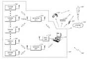
- FIG. 1shows a sensor system 100 that includes a plurality of sensor units 102 - 106 that communicate with a base unit 112 through a number of repeater units 110 - 111 .
- the sensor units 102 - 106are located throughout a building 101 .
- Sensor units 102 - 104communicate with the repeater 110 .
- Sensor units 105 - 106communicate with the repeater 111 .
- the repeaters 110 - 111communicate with the base unit 112 .
- the base unit 112communicates with a monitoring computer system 113 through a computer network connection such as, for example, Ethernet, wireless Ethernet, firewire port, Universal Serial Bus (USB) port, bluetooth, etc.
- USBUniversal Serial Bus
- the computer system 113contacts a building manager, maintenance service, alarm service, or other responsible personnel 120 using one or more of several communication systems such as, for example, telephone 121 , pager 122 , cellular telephone 123 (e.g., direct contact, voicemail, text, etc.), and/or through the Internet and/or local area network 124 (e.g., through email, instant messaging, network communications, etc.).
- multiple base units 112are provided to the monitoring computer 113 .
- the monitoring computer 113is provided to more than one computer monitor, thus, allowing more data to be displayed than can conveniently be displayed on a single monitor.
- the monitoring computer 113is provided to multiple monitors located in different locations, thus, allowing the data from the monitoring computer 113 to be displayed in multiple locations.
- the sensor units 102 - 106include sensors to measure conditions, such as, for example, smoke, temperature, moisture, water, water temperature, humidity, carbon monoxide, natural gas, propane gas, security alarms, intrusion alarms (e.g., open doors, broken windows, open windows, and the like), other flammable gases, radon, poison gasses, etc.
- Different sensor unitscan be configured with different sensors or with combinations of sensors.
- the sensor units 102 and 104could be configured with smoke and/or temperature sensors while the sensor unit 103 could be configured with a humidity sensor.
- the discussion that followsgenerally refers to the sensor unit 102 as an example of a sensor unit, with the understanding that the description of the sensor unit 102 can be applied to many sensor units.
- the discussiongenerally refers to the repeater 110 by way of example, and not limitation. It will also be understood by one of ordinary skill in the art that repeaters are useful for extending the range of the sensor units 102 - 106 but are not required in all embodiments. Thus, for example in one embodiment, one or more of the sensor units 102 - 106 can communicate directly with the base unit 112 without going through a repeater. It will also be understood by one of ordinary skill in the art that FIG.
- FIG. 1shows only five sensor units ( 102 - 106 ) and two repeater units ( 110 - 111 ) for purposes of illustration and not by way of limitation.
- An installation in a large apartment building or complexwould typically involve many sensor units and repeater units.
- one repeater unitcan service relatively many sensor units.
- the sensor units 102can communicate directly with the base unit 112 without going through a repeater 110 .
- the sensor unit 102When the sensor unit 102 detects an anomalous condition (e.g., smoke, fire, water, etc.) the sensor unit communicates with the appropriate repeater unit 110 and provides data regarding the anomalous condition.
- the repeater unit 110forwards the data to the base unit 112 , and the base unit 112 forwards the information to the computer 113 .
- the computer 113evaluates the data and takes appropriate action. If the computer 113 determines that the condition is an emergency (e.g., fire, smoke, large quantities of water), then the computer 113 contacts the appropriate personnel 120 . If the computer 113 determines that the situation warrants reporting, but is not an emergency, then the computer 113 logs the data for later reporting. In this way, the sensor system 100 can monitor the conditions in and around the building 101 .
- an emergencye.g., fire, smoke, large quantities of water
- the sensor unit 102has an internal power source (e.g., battery, solar cell, fuel cell, etc.). In order to conserve power, the sensor unit 102 is normally placed in a low-power mode. In one embodiment, using sensors that require relatively little power, while in the low-power mode the sensor unit 102 takes regular sensor readings and evaluates the readings to determine if an anomalous condition exists. In one embodiment, using sensors that require relatively more power, while in the low-power mode, the sensor unit 102 takes and evaluates sensor readings at periodic intervals. If an anomalous condition is detected, then the sensor unit 102 “wakes up” and begins communicating with the base unit 112 through the repeater 110 .
- an internal power sourcee.g., battery, solar cell, fuel cell, etc.
- the sensor unit 102also “wakes up” and sends status information (e.g., power levels, self diagnostic information, etc.) to the base unit (or repeater) and then listens for commands for a period of time.
- the sensor unit 102also includes a tamper detector. When tampering with the sensor unit 102 is detected, the sensor unit 102 reports such tampering to the base unit 112 .
- the sensor unit 102provides bi-directional communication and is configured to receive data and/or instructions from the base unit 112 .
- the base unit 112can instruct the sensor unit 102 to perform additional measurements, to go to a standby mode, to wake up, to report battery status, to change wake-up interval, to run self-diagnostics and report results, etc.
- the sensor unit 102reports its general health and status on a regular basis (e.g., results of self-diagnostics, battery health, etc.)
- the sensor unit 102provides two wake-up modes; a first wake-up mode for taking measurements (and reporting such measurements if deemed necessary), and a second wake-up mode for listening for commands from the central reporting station.
- the two wake-up modes, or combinations thereof,can occur at different intervals.
- the sensor unit 102uses spread-spectrum techniques to communicate with the repeater unit 110 . In one embodiment, the sensor unit 102 uses frequency-hopping spread-spectrum. In one embodiment, the sensor unit 102 has an address or identification (ID) code that distinguishes the sensor unit 102 from the other sensor units. The sensor unit 102 attaches its ID to outgoing communication packets so that transmissions from the sensor unit 102 can be identified by the repeater 110 . The repeater 110 attaches the ID of the sensor unit 102 to data and/or instructions that are transmitted to the sensor unit 102 . In one embodiment, the sensor unit 102 ignores data and/or instructions that are addressed to other sensor units.
- IDaddress or identification
- the sensor unit 102includes a reset function.
- the reset functionis activated by the reset switch 208 .
- the reset functionis active for a prescribed interval of time.
- the transceiver 203is in a receiving mode and can receive the identification code from an external programmer.
- the external programmerwirelessly transmits a desired identification code.
- the identification codeis programmed by an external programmer that is connected to the sensor unit 102 through an electrical connector.
- the electrical connection to the sensor unit 102is provided by sending modulated control signals (power line carrier signals) through a connector used to connect the power source 206 .
- the external programmerprovides power and control signals.
- the external programmeralso programs the type of sensor(s) installed in the sensor unit.
- the identification codeincludes an area code (e.g., apartment number, zone number, floor number, etc.) and a unit number (e.g., unit 1 , 2 , 3 , etc.).
- the senorcommunicates with the repeater on the 900 MHz band. This band provides good transmission through walls and other obstacles normally found in and around a building structure. In one embodiment, the sensor communicates with the repeater on bands above and/or below the 900 MHz band. In one embodiment, the sensor, repeater, and/or base unit listen to a radio frequency channel before transmitting on that channel or before beginning transmission. If the channel is in use, (e.g., by another device such as, another repeater, a cordless telephone, etc.) then the sensor, repeater, and/or base unit changes to a different channel.
- the senor, repeater, and/or base unitcoordinate frequency hopping by listening to radio frequency channels for interference and using an algorithm to select a next channel for transmission that avoids the interference.
- the sensorwill test (e.g., listen to) the channel before transmission to avoid channels that are blocked, in use, or jammed.
- the sensorcontinues to transmit data until it receives an acknowledgement from the base unit that the message has been received.
- the sensortransmits data having a normal priority (e.g., status information) and does not look for an acknowledgement, and the sensor transmits data having elevated priority (e.g., excess smoke, temperature, etc.) until an acknowledgement is received.
- a normal prioritye.g., status information
- elevated prioritye.g., excess smoke, temperature, etc.
- the repeater unit 110is configured to relay communications traffic between the sensor 102 (and, similarly, the sensor units 103 - 104 ) and the base unit 112 .
- the repeater unit 110typically operates in an environment with several other repeater units (such as the repeater unit 111 in FIG. 1 ) and thus, the repeater unit 110 contains a database (e.g., a lookup table) of sensor unit IDs.
- the repeater 110has database entries for the Ids of the sensors 102 - 104 , and thus, the sensor 110 will only communicate with sensor units 102 - 104 .
- the repeater 110has an internal power source (e.g., battery, solar cell, fuel cell, etc.) and conserves power by maintaining an internal schedule of when the sensor units 102 - 104 are expected to transmit. In one embodiment, the repeater unit 110 goes to a low-power mode when none of its designated sensor units is scheduled to transmit. In one embodiment, the repeater 110 uses spread-spectrum techniques to communicate with the base unit 112 and with the sensor units 102 - 104 . In one embodiment, the repeater 110 uses frequency-hopping spread-spectrum to communicate with the base unit 112 and the sensor units 102 - 104 .
- an internal power sourcee.g., battery, solar cell, fuel cell, etc.
- the repeater unit 110has an address or identification (ID) code and the repeater unit 110 attaches its address to outgoing communication packets that originate in the repeater (that is, packets that are not being forwarded). In one embodiment, the repeater unit 110 ignores data and/or instructions that are addressed to other repeater units or to sensor units not serviced by the repeater 110 .
- IDaddress or identification
- the base unit 112communicates with the sensor unit 102 by transmitting a communication packet addressed to the sensor unit 102 .
- the repeaters 110 and 111both receive the communication packet addressed to the sensor unit 102 .
- the repeater unit 111ignores the communication packet addressed to the sensor unit 102 .
- the repeater unit 110transmits the communication packet addressed to the sensor unit 102 to the sensor unit 102 .
- the sensor unit 102 , the repeater unit 110 , and the base unit 112communicate using Frequency-Hopping Spread Spectrum (FHSS), also known as channel-hopping.
- FHSSFrequency-Hopping Spread Spectrum
- Frequency-hopping wireless systemsoffer the advantage of avoiding other interfering signals and avoiding collisions. Moreover, there are regulatory advantages given to systems that do not transmit continuously at one frequency. Channel-hopping transmitters change frequencies after a period of continuous transmission, or when interference is encountered. These systems may have higher transmit power and relaxed limitations on in-band spurs. FCC regulations limit transmission time on one channel to 400 milliseconds (averaged over 10-20 seconds depending on channel bandwidth) before the transmitter must change frequency. There is a minimum frequency step when changing channels to resume transmission. If there are 25 to 49 frequency channels, regulations allow effective radiated power of 24 dBm, spurs must be ⁇ 20 dBc, and harmonics must be ⁇ 41.2 dBc. With 50 or more channels, regulations allow effective radiated power to be up to 30 dBm.
- the sensor unit 102 , the repeater unit 110 , and the base unit 112communicate using FHSS wherein the frequency hopping of the sensor unit 102 , the repeater unit 110 , and the base unit 112 are not synchronized such that at any given moment, the sensor unit 102 and the repeater unit 110 are on different channels.
- the base unit 112communicates with the sensor unit 102 using the hop frequencies synchronized to the repeater unit 110 rather than the sensor unit 102 .
- the repeater unit 110then forwards the data to the sensor unit using hop frequencies synchronized to the sensor unit 102 .
- Such a systemlargely avoids collisions between the transmissions by the base unit 112 and the repeater unit 110 .
- the sensor units 102 - 106all use FHSS and the sensor units 102 - 106 are not synchronized. Thus, at any given moment, it is unlikely that any two or more of the sensor units 102 - 106 will transmit on the same frequency. In this manner, collisions are largely avoided. In one embodiment, collisions are not detected but are tolerated by the system 100 . If a collision does occur, data lost due to the collision is effectively re-transmitted the next time the sensor units transmit sensor data. When the sensor units 102 - 106 and repeater units 110 - 111 operate in asynchronous mode, then a second collision is highly unlikely because the units causing the collisions have hopped to different channels.
- the sensor units 102 - 106 , repeater units 110 - 111 , and the base unit 112use the same hop rate. In one embodiment, the sensor units 102 - 106 , repeater units 110 - 111 , and the base unit 112 use the same pseudo-random algorithm to control channel hopping, but with different starting seeds. In one embodiment, the starting seed for the hop algorithm is calculated from the ID of the sensor units 102 - 106 , repeater units 110 - 111 , or the base unit 112 .
- the base unitcommunicates with the sensor unit 102 by sending a communication packet addressed to the repeater unit 112 , where the packet sent to the repeater unit 110 includes the address of the sensor unit 102 .
- the repeater unit 102extracts the address of the sensor unit 102 from the packet and creates and transmits a packet addressed to the sensor unit 102 .
- the repeater unit 110is configured to provide bi-directional communication between its sensors and the base unit 112 .
- the repeater 110is configured to receive instructions from the base unit 110 .
- the base unit 112can instruct the repeater to: send commands to one or more sensors; go to standby mode; “wake up”; report battery status; change wake-up interval; run self-diagnostics and report results; etc.
- the base unit 112is configured to receive measured sensor data from a number of sensor units either directly, or through the repeaters 110 - 111 .
- the base unit 112also sends commands to the repeater units 110 - 111 and/or to the sensor units 102 - 106 .
- the base unit 112communicates with a diskless computer 113 that runs off of a CD-ROM.
- the base unit 112receives data from a sensor unit 102 - 106 indicating that there may be an emergency condition (e.g., a fire or excess smoke, temperature, water, etc.) the computer 113 will attempt to notify the responsible party 120 .
- an emergency conditione.g., a fire or excess smoke, temperature, water, etc.
- the computer 112maintains a database of the health, power status (e.g., battery charge), and current operating status of all of the sensor units 102 - 106 and the repeater units 110 - 111 .
- the computer 113automatically performs routine maintenance by sending commands to each sensor units 102 - 106 to run a self-diagnostic and report the results. The computer 113 collects and logs such diagnostic results.
- the computer 113sends instructions to each sensor units 102 - 106 telling the sensor how long to wait between “wakeup” intervals.
- the computer 113schedules different wakeup intervals to different sensor units 102 - 106 based on the sensor unit's health, power status, location, etc.
- the computer 113schedules different wakeup intervals to different sensor units 102 - 106 based on the type of data and urgency of the data collected by the sensor unit (e.g., sensor units that have smoke and/or temperature sensors produce data that should be checked relatively more often than sensor units that have humidity or moisture sensors).
- the base unitsends instructions to repeaters to route sensor information around a failed repeater.
- the computer 113produces a display that tells maintenance personnel which sensor units 102 - 106 need repair or maintenance. In one embodiment, the computer 113 maintains a list showing the status and/or location of each sensor according to the ID of each sensor.
- the sensor units 102 - 106 and/or the repeater units 110 - 111measure the signal strength of the wireless signals received (e.g., the sensor unit 102 measures the signal strength of the signals received from the repeater unit 110 , the repeater unit 110 measures the signal strength received from the sensor unit 102 and/or the base unit 112 ).
- the sensor units 102 - 106 and/or the repeater units 110 - 111report such signal strength measurement back to the computer 113 .
- the computer 113evaluates the signal strength measurements to ascertain the health and robustness of the sensor system 100 .
- the computer 113uses the signal strength information to re-route wireless communications traffic in the sensor system 100 .
- the computer 113can send instructions to the repeater unit 111 to add the ID of the sensor unit 102 to the database of the repeater unit 111 (and similarly, send instructions to the repeater unit 110 to remove the ID of the sensor unit 102 ), thereby routing the traffic for the sensor unit 102 through the router unit 111 instead of the router unit 110 .
- FIG. 2is a block diagram of the sensor unit 102 .
- the sensor unit 102one or more sensors 201 and a transceiver 203 are provided to a controller 202 .
- the controller 202typically provides power, data, and control information to the sensor(s) 201 and the transceiver 203 .
- a power source 206is provided to the controller 202 .
- An optional tamper sensor 205is also provided to the controller 202 .
- a reset device (e.g., a switch) 208is provided to the controller 202 .
- an optional audio output device 209is provided.
- the sensor 201is configured as a plug-in module that can be replaced relatively easily.
- the transceiver 203is based on a TRF 6901 transceiver chip from Texas Instruments. Inc.
- the controller 202is a conventional programmable microcontroller.
- the controller 202is based on a Field Programmable Gate Array (FPGA), such as, for example, provided by Xilinx Corp.
- the sensor 201includes an optoelectric smoke sensor with a smoke chamber.
- the sensor 201includes a thermistor.
- the sensor 201includes a humidity sensor.
- the sensor 201includes a sensor, such as, for example, a water level sensor, a water temperature sensor, a carbon monoxide sensor, a moisture sensor, a water flow sensor, natural gas sensor, propane sensor, etc.
- the controller 202receives sensor data from the sensor(s) 201 . Some sensor(s) 201 produce digital data. However, for many types of sensor(s) 201 , the sensor data is analog data. Analog sensor data is converted to digital format by the controller 202 . In one embodiment, the controller evaluates the data received from the sensor(s) 201 and determines whether the data is to be transmitted to the base unit 112 . The sensor unit 102 generally conserves power by not transmitting data that falls within a normal range. In one embodiment, the controller 202 evaluates the sensor data by comparing the data value to a threshold value (e.g., a high threshold, a low threshold, or a high-low threshold).
- a threshold valuee.g., a high threshold, a low threshold, or a high-low threshold
- the data thresholdis programmed into the controller 202 .
- the data thresholdis programmed by the base unit 112 by sending instructions to the controller 202 .
- the controller 202obtains sensor data and transmits the data when commanded by the computer 113 .
- the tamper sensor 205is configured as a switch that detects removal of/or tampering with the sensor unit 102 .
- FIG. 3is a block diagram of the repeater unit 110 .
- a first transceiver 302 and a second transceiver 304are provided to a controller 303 .
- the controller 303typically provides power, data, and control information to the transceivers 302 , 304 .
- a power source 306is provided to the controller 303 .
- An optional tamper sensor(not shown) is also provided to the controller 303 .
- the controller 303When relaying sensor data to the base unit 112 , the controller 303 receives data from the first transceiver 303 and provides the data to the second transceiver 304 . When relaying instructions from the base unit 112 to a sensor unit, the controller 303 receives data from the second transceiver 304 and provides the data to the first transceiver 302 . In one embodiment, the controller 303 conserves power by powering-down the transceivers 302 , 304 during periods when the controller 303 is not expecting data. The controller 303 also monitors the power source 306 and provides status information, such as, for example, self-diagnostic information and/or information about the health of the power source 306 , to the base unit 112 .
- status informationsuch as, for example, self-diagnostic information and/or information about the health of the power source 306
- the controller 303sends status information to the base unit 112 at regular intervals. In one embodiment, the controller 303 sends status information to the base unit 112 when requested by the base unit 112 . In one embodiment, the controller 303 sends status information to the base unit 112 when a fault condition (e.g., battery low) is detected.
- a fault conditione.g., battery low
- the controller 303includes a table or list of identification codes for wireless sensor units 102 .
- the repeater 303forwards packets received from, or sent to, sensor units 102 in the list.
- the repeater 110receives entries for the list of sensor units from the computer 113 .
- the controller 303determines when a transmission is expected from the sensor units 102 in the table of sensor units and places the repeater 110 (e.g., the transceivers 302 , 304 ) in a low-power mode when no transmissions are expected from the transceivers on the list.
- the controller 303recalculates the times for low-power operation when a command to change reporting interval is forwarded to one of the sensor units 102 in the list (table) of sensor units or when a new sensor unit is added to the list (table) of sensor units.
- FIG. 4is a block diagram of the base unit 112 .
- a transceiver 402 and a computer interface 404are provided to a controller 403 .
- the controller 303typically provides data and control information to the transceivers 402 and to the interface.
- the interface 404is provided to a port on the monitoring computer 113 .
- the interface 404can be a standard computer data interface, such as, for example, Ethernet, wireless Ethernet, firewire port, Universal Serial Bus (USB) port, bluetooth, etc.
- USBUniversal Serial Bus
- FIG. 5shows one embodiment of a communication packet 500 used by the sensor units, repeater units, and the base unit.
- the packet 500includes a preamble portion 501 , an address (or ID) portion 502 , a data payload portion 503 , and an integrity portion 504 .
- the integrity portion 504includes a checksum.
- the sensor units 102 - 106 , the repeater units 110 - 111 , and the base unit 112communicate using packets such as the packet 500 .
- the packets 500are transmitted using FHSS.
- the data packets that travel between the sensor unit 102 , the repeater unit 111 , and the base unit 112are encrypted. In one embodiment, the data packets that travel between the sensor unit 102 , the repeater unit 111 , and the base unit 112 are encrypted and an authentication code is provided in the data packet so that the sensor unit 102 , the repeater unit, and/or the base unit 112 can verify the authenticity of the packet.
- the address portion 502includes a first code and a second code.
- the repeater 111only examines the first code to determine if the packet should be forwarded.
- the first codecan be interpreted as a building (or building complex) code and the second code interpreted as a subcode (e.g., an apartment code, area code, etc.).
- a repeater that uses the first code for forwardingthus, forwards packets having a specified first code (e.g., corresponding to the repeater's building or building complex).
- a specified first codee.g., corresponding to the repeater's building or building complex.
- a repeater so configuredonly needs to know the first code to forward packets for any repeater in the building or building complex. This does, however, raise the possibility that two repeaters in the same building could try to forward packets for the same sensor unit 102 .
- each repeaterwaits for a programmed delay period before forwarding a packet. Thus reducing the chance of packet collisions at the base unit (in the case of sensor unit to base unit packets) and reducing the chance of packet collisions at the sensor unit (in the case of base unit to sensor unit packets).
- a delay periodis programmed into each repeater. In one embodiment, delay periods are pre-programmed onto the repeater units at the factory or during installation.
- a delay periodis programmed into each repeater by the base unit 112 .
- a repeaterrandomly chooses a delay period.
- a repeaterrandomly chooses a delay period for each forwarded packet.
- the first codeis at least 6 digits.
- the second codeis at least 5 digits.
- the first code and the second codeare programmed into each sensor unit at the factory. In one embodiment, the first code and the second code are programmed when the sensor unit is installed. In one embodiment, the base unit 112 can re-program the first code and/or the second code in a sensor unit.
- collisionsare further avoided by configuring each repeater unit 111 to begin transmission on a different frequency channel.
- each repeater unit 111configuring each repeater unit 111 to begin transmission on a different frequency channel.
- FIG. 6is a flowchart showing one embodiment of the operation of the sensor unit 102 wherein relatively continuous monitoring is provided.
- a power up block 601is followed by an initialization block 602 .
- the sensor unit 102checks for a fault condition (e.g., activation of the tamper sensor, low battery, internal fault, etc.) in a block 603 .
- a decision block 604checks the fault status. If a fault has occurred, then the process advances to a block 605 were the fault information is transmitted to the repeater 110 (after which, the process advances to a block 612 ); otherwise, the process advances to a block 606 .
- the sensor unit 102takes a sensor reading from the sensor(s) 201 .
- the sensor datais subsequently evaluated in a block 607 . If the sensor data is abnormal, then the process advances to a transmit block 609 where the sensor data is transmitted to the repeater 110 (after which, the process advances to a block 612 ); otherwise, the process advances to a timeout decision block 610 . If the timeout period has not elapsed, then the process returns to the fault-check block 603 ; otherwise, the process advances to a transmit status block 611 where normal status information is transmitted to the repeater 110 .
- the normal status information transmittedis analogous to a simple “ping” which indicates that the sensor unit 102 is functioning normally.
- transceiver 203is normally powered down.
- the controller 202powers up the transceiver 203 during execution of the blocks 605 , 609 , 611 , and 612 .
- the monitoring computer 113can send instructions to the sensor unit 102 to change the parameters used to evaluate data used in block 607 , the listen period used in block 612 , etc.
- FIG. 7is a flowchart showing one embodiment of operation of the sensor unit 102 wherein periodic monitoring is provided.
- a power up block 701is followed by an initialization block 702 . After initialization, the sensor unit 102 enters a low-power sleep mode.
- the processenters a wake-up block 704 followed by a transmit fault block 705 . If no fault occurs during the sleep period, then when the specified sleep period has expired, the process enters a block 706 where the sensor unit 102 takes a sensor reading from the sensor(s) 201 . The sensor data is subsequently sent to the monitoring computer 113 in a report block 707 . After reporting, the sensor unit 102 enters a listen block 708 where the sensor unit 102 listens for a relatively short period of time for instructions from monitoring computer 708 . If an instruction is received, then the sensor unit 102 performs the instructions, otherwise, the process returns to the sleep block 703 .
- a faultoccurs during the sleep mode (e.g., the tamper sensor is activated)
- the processenters a wake-up block 704 followed by a transmit fault block 705 . If no fault occurs during the sleep period, then when the specified sleep period has expired, the process enters a block 706 where the sensor unit 102 takes a sensor reading from
- the senor 201 and transceiver 203are normally powered down.
- the controller 202powers up the sensor 201 during execution of the block 706 .
- the controller 202powers up the transceiver during execution of the blocks 705 , 707 , and 708 .
- the monitoring computer 113can send instructions to the sensor unit 102 to change the sleep period used in block 703 , the listen period used in block 708 , etc.
- the sensor unittransmits sensor data until a handshaking-type acknowledgement is received.
- the sensor unit 102retransmits its data and waits for an acknowledgement.
- the sensor unit 102continues to transmit data and wait for an acknowledgement until an acknowledgement is received.
- the sensor unitaccepts an acknowledgement from a repeater unit 111 and it then becomes the responsibility of the repeater unit 111 to make sure that the data is forwarded to the base unit 112 .
- the repeater unit 111does not generate the acknowledgement, but rather forwards an acknowledgement from the base unit 112 to the sensor unit 102 .
- the two-way communication ability of the sensor unit 102provides the capability for the base unit 112 to control the operation of the sensor unit 102 and also provides the capability for robust handshaking-type communication between the sensor unit 102 and the base unit 112 .
- the monitoring computer 113can instruct the sensor unit 102 to operate in a relatively continuous mode where the sensor repeatedly takes sensor readings and transmits the readings to the monitoring computer 113 .
- a relatively continuous modewhere the sensor repeatedly takes sensor readings and transmits the readings to the monitoring computer 113 .
- Such a modewould can be used, for example, when the sensor unit 102 (or a nearby sensor unit) has detected a potentially dangerous condition (e.g., smoke, rapid temperature rise, etc.)
- FIG. 8shows the sensor system used to detect water leaks.
- the sensor unit 102includes a water level sensor 803 and/or a water temperature sensor 804 .
- the water level sensor 803 and/or water temperature sensor 804are placed, for example, in a tray underneath a water heater 801 in order to detect leaks from the water heater 801 and, thereby, prevent water damage from a leaking water heater.
- a temperature sensoris also provided to measure temperature near the water heater.
- the water level sensorcan also be placed under a sink, in a floor sump, etc.
- the severity of a leakis ascertained by the sensor unit 102 (or the monitoring computer 113 ) by measuring the rate of rise in the water level.
- the severity of a leakcan also be ascertained at least in part by measuring the temperature of the water.
- a first water flow sensoris placed in an input water line for the hot water tank 801 and a second water flow sensor is placed in an output water line for the hot water tank. Leaks in the tank can be detected by observing a difference between the water flowing through the two sensors.
- a remote shutoff valve 810is provided, so that the monitoring system 100 can shutoff the water supply to the water heater when a leak is detected.
- the shutoff valveis controlled by the sensor unit 102 .
- the sensor unit 102receives instructions from the base unit 112 to shut off the water supply to the heater 801 .
- the responsible party 120sends instructions to the monitoring computer 113 instructing the monitoring computer 113 to send water shut off instructions to the sensor unit 102 .
- the sensor unit 102controls a gas shutoff valve 811 to shut off the gas supply to the water heater 801 and/or to a furnace (not shown) when dangerous conditions (such as, for example, gas leaks, carbon monoxide, etc.) are detected.
- a gas detector 812is provided to the sensor unit 102 .
- the gas detector 812measures carbon monoxide.
- the gas detector 812measures flammable gas, such as, for example, natural gas or propane.
- an optional temperature sensor 818is provided to measure stack temperature. Using data from the temperature sensor 818 , the sensor unit 102 reports conditions, such as, for example, excess stack temperature. Excess stack temperature is often indicative of poor heat transfer (and thus, poor efficiency) in the water heater 801 .
- an optional temperature sensor 818is provided to measure temperature of water in the water heater 801 . Using data from the temperature sensor 819 , the sensor unit 102 reports conditions, such as, for example, over-temperature or under-temperature of the water in the water heater.
- an optional current probe 821is provided to measure electric current provided to a heating element 820 in an electric water heater.
- the sensor unit 102uses data from the current probe 821 to report conditions, such as, for example, no current (indicating a burned-out heating element 820 ).
- An over-current conditionoften indicates that the heating element 820 is encrusted with mineral deposits and needs to be replaced or cleaned.
- the monitoring systemcan measure the amount of energy provided to the water heater and thus the cost of hot water, and the efficiency of the water heater.
- the senor 803includes a moisture sensor. Using data from the moisture sensor, the sensor unit 102 reports moisture conditions, such as, for example, excess moisture that would indicate a water leak, excess condensation, etc.
- the sensor unit 102is provided to a moisture sensor (such as the sensor 803 ) located near an air conditioning unit. Using data from the moisture sensor, the sensor unit 102 reports moisture conditions, such as, for example, excess moisture that would indicate a water leak, excess condensation, etc.
- the senor 201includes a moisture sensor.
- the moisture sensorcan be place under a sink or a toilet (to detect plumbing leaks) or in an attic space (to detect roof leaks).
- the sensor 201includes a humidity sensor.
- the humidity sensorcan be placed under a sink, in an attic space, etc., to detect excess humidity (due to leaks, condensation, etc.).
- the monitoring computer 113compares humidity measurements taken from different sensor units in order to detect areas that have excess humidity. Thus, for example, the monitoring computer 113 can compare the humidity readings from a first sensor unit 102 in a first attic area, to a humidity reading from a second sensor unit 102 in a second area.
- the monitoring computercan take humidity readings from a number of attic areas to establish a baseline humidity reading and then compare the specific humidity readings from various sensor units to determine if one or more of the units are measuring excess humidity.
- the monitoring computer 113would flag areas of excess humidity for further investigation by maintenance personnel.
- the monitoring computer 113maintains a history of humidity readings for various sensor units and flags areas that show an unexpected increase in humidity for investigation by maintenance personnel.
- the monitoring system 100detects conditions favorable for fungus (e.g., mold, mildew, fungus, etc.) growth by using a first humidity sensor located in a first building area to produce first humidity data and a second humidity sensor located in a second building area to produce second humidity data.
- the building areascan be, for example, areas near a sink drain, plumbing fixture, plumbing, attic areas, outer walls, a bilge area in a boat, etc.
- the monitoring station 113collects humidity readings from the first humidity sensor and the second humidity sensor and indicates conditions favorable for fungus growth by comparing the first humidity data and the second humidity data. In one embodiment, the monitoring station 113 establishes a baseline humidity by comparing humidity readings from a plurality of humidity sensors and indicates possible fungus growth conditions in the first building area when at least a portion of the first humidity data exceeds the baseline humidity by a specified amount. In one embodiment, the monitoring station 113 establishes a baseline humidity by comparing humidity readings from a plurality of humidity sensors and indicates possible fungus growth conditions in the first building area when at least a portion of the first humidity data exceeds the baseline humidity by a specified percentage.
- the monitoring station 113establishes a baseline humidity history by comparing humidity readings from a plurality of humidity sensors and indicates possible fungus growth conditions in the first building area when at least a portion of the first humidity data exceeds the baseline humidity history by a specified amount over a specified period of time. In one embodiment, the monitoring station 113 establishes a baseline humidity history by comparing humidity readings from a plurality of humidity sensors over a period of time and indicates possible fungus growth conditions in the first building area when at least a portion of the first humidity data exceeds the baseline humidity by a specified percentage of a specified period of time.
- the sensor unit 102transmits humidity data when it determines that the humidity data fails a threshold test.
- the humidity threshold for the threshold testis provided to the sensor unit 102 by the monitoring station 113 .
- the humidity threshold for the threshold testis computed by the monitoring station from a baseline humidity established in the monitoring station.
- the baseline humidityis computed at least in part as an average of humidity readings from a number of humidity sensors.
- the baseline humidityis computed at least in part as a time average of humidity readings from a number of humidity sensors.
- the baseline humidityis computed at least in part as a time average of humidity readings from a humidity sensor.
- the baseline humidityis computed at least in part as the lesser of a maximum humidity reading an average of a number of humidity readings.
- the sensor unit 102reports humidity readings in response to a query by the monitoring station 113 . In one embodiment, the sensor unit 102 reports humidity readings at regular intervals. In one embodiment, a humidity interval is provided to the sensor unit 102 by the monitoring station 113 .
- the calculation of conditions for fungus growthis comparing humidity readings from one or more humidity sensors to the baseline (or reference) humidity. In one embodiment, the comparison is based on comparing the humidity readings to a percentage (e.g., typically a percentage greater than 100%) of the baseline value. In one embodiment, the comparison is based on comparing the humidity readings to a specified delta value above the reference humidity. In one embodiment, the calculation of likelihood of conditions for fungus growth is based on a time history of humidity readings, such that the longer the favorable conditions exist, the greater the likelihood of fungus growth. In one embodiment, relatively high humidity readings over a period of time indicate a higher likelihood of fungus growth than relatively high humidity readings for short periods of time.
- a relatively sudden increase in humidity as compared to a baseline or reference humidityis reported by the monitoring station 113 as a possibility of a water leak. If the relatively high humidity reading continues over time then the relatively high humidity is reported by the monitoring station 113 as possibly being a water leak and/or an area likely to have fungus growth or water damage.
- Temperatures relatively more favorable to fungus growthincrease the likelihood of fungus growth.
- temperature measurements from the building areasare also used in the fungus grown-likelihood calculations.
- a threshold value for likelihood of fungus growthis computed at least in part as a function of temperature, such that temperatures relatively more favorable to fungus growth result in a relatively lower threshold than temperatures relatively less favorable for fungus growth.
- the calculation of a likelihood of fungus growthdepends at least in part on temperature such that temperatures relatively more favorable to fungus growth indicate a relatively higher likelihood of fungus growth than temperatures relatively less favorable for fungus growth.
- a maximum humidity and/or minimum threshold above a reference humidityis relatively lower for temperature more favorable to fungus growth than the maximum humidity and/or minimum threshold above a reference humidity for temperatures relatively less favorable to fungus growth.
- a water flow sensoris provided to the sensor unit 102 .
- the sensor unit 102obtains water flow data from the water flow sensor and provides the water flow data to the monitoring computer 113 .
- the monitoring computer 113can then calculate water usage. Additionally, the monitoring computer can watch for water leaks, by, for example, looking for water flow when there should be little or no flow. Thus, for example, if the monitoring computer detects water usage throughout the night, the monitoring computer can raise an alert indicating that a possible water leak has occurred.
- the sensor 201includes a water flow sensor is provided to the sensor unit 102 .
- the sensor unit 102obtains water flow data from the water flow sensor and provides the water flow data to the monitoring computer 113 .
- the monitoring computer 113can then calculate water usage. Additionally, the monitoring computer can watch for water leaks, by, for example, looking for water flow when there should be little or no flow. Thus, for example, if the monitoring computer detects water usage throughout the night, the monitoring computer can raise an alert indicating that a possible water leak has occurred.
- the sensor 201which includes a fire-extinguisher tamper sensor, is provided to the sensor unit 102 .
- the fire-extinguisher tamper sensorreports tampering with or use of a fire-extinguisher.
- the fire-extinguisher temper sensorreports that the fire extinguisher has been removed from its mounting, that a fire extinguisher compartment has been opened, and/or that a safety lock on the fire extinguisher has been removed.
- FIG. 9is a flowchart 900 showing one embodiment for configuring the sensor system by labeling sensor units according to an intended location and providing computer data to correlate a sensor identification code with a sensor location.
- the flowchart 900begins with a process block 901 wherein a user or other person specifying a sensor system produces a list of sensor locations including location data for each sensor.
- the location datacan specify the type of sensor (smoke, water, gas, etc.) and the location of the sensor.
- the location data for the sensorcan be specified by apartment number, location in an apartment (e.g., kitchen, hallway, bedroom, etc.).
- the location datacan also specify the building (e.g., by address, building number, etc.) and/or floor number.
- the location datacan also specify the location of the sensor by type, location (e.g., building, building area, etc.), and the like.
- portions of the process block 901are performed by using the Internet.
- the user or person specifying the systemuses a World Wide Web (web) browser (e.g., Microsoft Internet Explorer, Mozilla, Firefox, etc.) to visit a website that provides for ordering the sensor system.
- the user or person specifying the systemuses the web browser to input the list of sensor locations and, optionally, to specify the sensor type at each location.
- the usercan also specify the number of repeaters and which sensors are served by each repeater.
- the processthen advances to a process block 902 where the location data is provided to a programming facility (e.g., a manufacturing facility, sales or distribution facility, on-site programming facility, etc.).
- a programming facilitye.g., a manufacturing facility, sales or distribution facility, on-site programming facility, etc.
- the processthen advances to a process block 903 where the programming facility produces a list of sensor ID's corresponding to the sensor locations.
- an sensor identification codeis provided for each sensor at each specified location.
- the processthen advances to a process block 904 where the list of sensor locations and corresponding sensor identification codes is stored as system configuration data for later recall.
- the processthen advances to a process block 905 where each sensor is labeled.
- each sensoris labeled according to its intended location so that an installer can easily identify where each sensor is to be placed.
- the sensor labelincludes the identification code.
- the sensor labelincludes a bar code. In one embodiment, the sensor label includes the sensor type.
- the processthen advances to a process block 906 wherein the labeled sensor units and a computer-readable media or network location containing the system configuration data are provided to the user.
- the system configuration dataincludes the list of sensor locations and corresponding sensor identification codes.
- the computer-readable media (or network locationcan be provided to the control system 113 to configure the sensor system so that the control system 113 knows which sensors are installed, their identification numbers, and locations. Thus, the control system 113 knows which sensors to monitor and where to report sensor locations when a sensor reports an anomalous condition.
- FIG. 10is a flowchart 1000 for one embodiment for adding sensors to an existing system.
- the flowchart 1000begins with a process block 1001 wherein a user or other person specifying a sensor system produces produce a list of additional sensor locations including location data for each additional sensor unit to be added to the system.
- portions of the process block 1001are performed by using the Internet.
- the user or person specifying the systemuses a web browser to input the list of additional sensor locations and, optionally, to specify the sensor type at each location.
- the usercan also specify the number of repeaters and which sensors are served by each repeater.
- the processthen advances to a process block 1002 where the location data is provided to a programming facility (e.g., a manufacturing facility, sales or distribution facility, on-site programming facility, etc.).
- a programming facilitye.g., a manufacturing facility, sales or distribution facility, on-site programming facility, etc.
- the processthen advances to a process block 1003 where the programming facility retrieve the stored list of sensor locations and identification codes for the sensor system.
- the processthen advances to process blocks 1004 and 1005 , where the programming facility adds sensor ID's and location data corresponding to the new sensor locations to the list of sensor location are added to the system configuration data and stored.
- the processthen advances to a process block where the list of sensor identification codes and sensor locations (including the data for the new sensors) is stored.
- the processthen advances to a process block 1007 where the new sensors a labeled with location information (and optionally identification information and/or barcode information).
- the processthen advances to a process block 1008 where the new labeled sensor units and a computer-readable copy of the list of the system configuration data is provided to the user.
- the wireless systemcan be configured to operate on one or more frequency bands, such as, for example, the HF band, the VHF band, the UHF band, the Microwave band, the Millimeter wave band, etc.
- modulation usesis not limited to any particular modulation method, such that modulation scheme used can be, for example, frequency modulation, phase modulation, amplitude modulation, combinations thereof, etc.
- modulation scheme usedcan be, for example, frequency modulation, phase modulation, amplitude modulation, combinations thereof, etc.
Landscapes
- Physics & Mathematics (AREA)
- General Physics & Mathematics (AREA)
- Business, Economics & Management (AREA)
- Emergency Management (AREA)
- Engineering & Computer Science (AREA)
- Computer Networks & Wireless Communication (AREA)
- Chemical & Material Sciences (AREA)
- Health & Medical Sciences (AREA)
- Combustion & Propulsion (AREA)
- Environmental & Geological Engineering (AREA)
- General Health & Medical Sciences (AREA)
- Toxicology (AREA)
- Analytical Chemistry (AREA)
- Alarm Systems (AREA)
- Arrangements For Transmission Of Measured Signals (AREA)
- Mobile Radio Communication Systems (AREA)
Abstract
Description
Claims (30)
Priority Applications (10)
| Application Number | Priority Date | Filing Date | Title |
|---|---|---|---|
| US11/231,321US7230528B2 (en) | 2005-09-20 | 2005-09-20 | Programmed wireless sensor system |
| JP2008531119AJP2009509237A (en) | 2005-09-20 | 2006-08-18 | Programmed wireless sensor system |
| CNA2006800386301ACN101292273A (en) | 2005-09-20 | 2006-08-18 | Programmed wireless sensor system |
| EP06789855AEP1927090A1 (en) | 2005-09-20 | 2006-08-18 | Programmed wireless sensor system |
| RU2008114637/11ARU2008114637A (en) | 2005-09-20 | 2006-08-18 | WIRELESS SOFTWARE SYSTEM WITH SOFTWARE CONTROL |
| CA002623003ACA2623003A1 (en) | 2005-09-20 | 2006-08-18 | Programmed wireless sensor system |
| PCT/US2006/032309WO2007035219A1 (en) | 2005-09-20 | 2006-08-18 | Programmed wireless sensor system |
| KR1020087009088AKR20080045293A (en) | 2005-09-20 | 2006-08-18 | Programmed wireless sensor system |
| AU2006292764AAU2006292764A1 (en) | 2005-09-20 | 2006-08-18 | Programmed wireless sensor system |
| US11/761,845US20070229237A1 (en) | 2005-09-20 | 2007-06-12 | Programmed wireless sensor system |
Applications Claiming Priority (1)
| Application Number | Priority Date | Filing Date | Title |
|---|---|---|---|
| US11/231,321US7230528B2 (en) | 2005-09-20 | 2005-09-20 | Programmed wireless sensor system |
Related Child Applications (1)
| Application Number | Title | Priority Date | Filing Date |
|---|---|---|---|
| US11/761,845ContinuationUS20070229237A1 (en) | 2005-09-20 | 2007-06-12 | Programmed wireless sensor system |
Publications (2)
| Publication Number | Publication Date |
|---|---|
| US20070063833A1 US20070063833A1 (en) | 2007-03-22 |
| US7230528B2true US7230528B2 (en) | 2007-06-12 |
Family
ID=37450945
Family Applications (2)
| Application Number | Title | Priority Date | Filing Date |
|---|---|---|---|
| US11/231,321Expired - LifetimeUS7230528B2 (en) | 2005-09-20 | 2005-09-20 | Programmed wireless sensor system |
| US11/761,845AbandonedUS20070229237A1 (en) | 2005-09-20 | 2007-06-12 | Programmed wireless sensor system |
Family Applications After (1)
| Application Number | Title | Priority Date | Filing Date |
|---|---|---|---|
| US11/761,845AbandonedUS20070229237A1 (en) | 2005-09-20 | 2007-06-12 | Programmed wireless sensor system |
Country Status (9)
| Country | Link |
|---|---|
| US (2) | US7230528B2 (en) |
| EP (1) | EP1927090A1 (en) |
| JP (1) | JP2009509237A (en) |
| KR (1) | KR20080045293A (en) |
| CN (1) | CN101292273A (en) |
| AU (1) | AU2006292764A1 (en) |
| CA (1) | CA2623003A1 (en) |
| RU (1) | RU2008114637A (en) |
| WO (1) | WO2007035219A1 (en) |
Cited By (73)
| Publication number | Priority date | Publication date | Assignee | Title |
|---|---|---|---|---|
| US20060007008A1 (en)* | 2004-05-27 | 2006-01-12 | Lawrence Kates | Method and apparatus for detecting severity of water leaks |
| US20060155818A1 (en)* | 2004-12-30 | 2006-07-13 | Thomas Odenwald | Sensor node management |
| US20060267756A1 (en)* | 2004-05-27 | 2006-11-30 | Lawrence Kates | System and method for high-sensitivity sensor |
| US20060273896A1 (en)* | 2005-06-06 | 2006-12-07 | Lawrence Kates | System and method for variable threshold sensor |
| US20070090946A1 (en)* | 2004-05-27 | 2007-04-26 | Lawrence Kates | Wireless sensor unit |
| US20070139208A1 (en)* | 2005-09-23 | 2007-06-21 | Lawrence Kates | Method and apparatus for detecting moisture in building materials |
| US20070139183A1 (en)* | 2005-12-19 | 2007-06-21 | Lawrence Kates | Portable monitoring unit |
| US20070179754A1 (en)* | 2006-01-30 | 2007-08-02 | Sper Scientific Ltd. | Wireless meter for real time measurements and method therefor |
| US20070211076A1 (en)* | 2004-05-27 | 2007-09-13 | Lawrence Kates | Method and apparatus for detecting water leaks |
| US20070229237A1 (en)* | 2005-09-20 | 2007-10-04 | Lawrence Kates | Programmed wireless sensor system |
| US20080067249A1 (en)* | 2006-06-02 | 2008-03-20 | Yasumasa Nakatsugawa | Data Communications System, Information Processing Terminal, IC Card, Reader/Writer, and Program |
| US7362230B1 (en)* | 2007-03-14 | 2008-04-22 | Dan Fish | Leak detection apparatus |
| US20080136606A1 (en)* | 2006-12-06 | 2008-06-12 | Electronics And Telecommunications Research Institute | Separable device for controlling node and sensor network node |
| US20080150714A1 (en)* | 2006-11-30 | 2008-06-26 | International Business Machines Corporation | Method for reducing power consumption of sensors |
| US7412876B2 (en) | 2004-09-23 | 2008-08-19 | Lawrence Kates | System and method for utility metering and leak detection |
| US20090033507A1 (en)* | 2007-08-03 | 2009-02-05 | Vokey David E | Moisture monitoring system for buildings |
| WO2009018650A1 (en)* | 2007-08-03 | 2009-02-12 | Detec Systems Llc | A moisture monitoring system for buildings |
| US20090113244A1 (en)* | 2007-10-30 | 2009-04-30 | Cisco Technology, Inc. | Diagnostic Functionality for Wireless Client Connectivity Problems in Wireless Networks |
| US20090303993A1 (en)* | 2008-06-05 | 2009-12-10 | Smart Warning Systems, Llc D/B/A Metis Secure Solutions | Emergency alerting device |
| US20100059217A1 (en)* | 2008-03-03 | 2010-03-11 | Satellite Systems & Solutions, Inc. | Method and Apparatus for Mitigating Environmental Impact Due to Fluid Leaks |
| US20100225464A1 (en)* | 2007-09-14 | 2010-09-09 | Bridgestone Corporation | Tire state variables management system |
| US20110110792A1 (en)* | 2009-11-12 | 2011-05-12 | Joseph Kendall Mauro | Sensors and methods and apparatus relating to same |
| US20110110794A1 (en)* | 2009-11-12 | 2011-05-12 | Philip Mayleben | Sensors and methods and apparatus relating to same |
| US20110131320A1 (en)* | 2007-12-17 | 2011-06-02 | Electronics And Telecommunications Research Institute | Apparatus and method of dynamically managing sensor module on sensor node in wireless sensor network |
| US8134462B1 (en)* | 2008-08-08 | 2012-03-13 | The United States Of America As Represented By The Secretary Of The Navy | Self-contained sensor package for water security and safety |
| US8380355B2 (en) | 2007-03-19 | 2013-02-19 | Wayne/Scott Fetzer Company | Capacitive sensor and method and apparatus for controlling a pump using same |
| US8964338B2 (en) | 2012-01-11 | 2015-02-24 | Emerson Climate Technologies, Inc. | System and method for compressor motor protection |
| US9121407B2 (en) | 2004-04-27 | 2015-09-01 | Emerson Climate Technologies, Inc. | Compressor diagnostic and protection system and method |
| US9140728B2 (en) | 2007-11-02 | 2015-09-22 | Emerson Climate Technologies, Inc. | Compressor sensor module |
| US20150382228A1 (en)* | 2013-03-07 | 2015-12-31 | Fujitsu Limited | Data collection method, system, and computer product |
| US9285802B2 (en) | 2011-02-28 | 2016-03-15 | Emerson Electric Co. | Residential solutions HVAC monitoring and diagnosis |
| US9310439B2 (en) | 2012-09-25 | 2016-04-12 | Emerson Climate Technologies, Inc. | Compressor having a control and diagnostic module |
| US9310094B2 (en) | 2007-07-30 | 2016-04-12 | Emerson Climate Technologies, Inc. | Portable method and apparatus for monitoring refrigerant-cycle systems |
| WO2016190856A1 (en)* | 2015-05-27 | 2016-12-01 | Hewlett Packard Enterprise Development Lp | Data validation |
| US9551504B2 (en) | 2013-03-15 | 2017-01-24 | Emerson Electric Co. | HVAC system remote monitoring and diagnosis |
| US9638436B2 (en) | 2013-03-15 | 2017-05-02 | Emerson Electric Co. | HVAC system remote monitoring and diagnosis |
| US20170138775A1 (en)* | 2013-03-15 | 2017-05-18 | Ruskin Company | Gas flow measurement system and method of operation |
| US9765979B2 (en) | 2013-04-05 | 2017-09-19 | Emerson Climate Technologies, Inc. | Heat-pump system with refrigerant charge diagnostics |
| US9803902B2 (en) | 2013-03-15 | 2017-10-31 | Emerson Climate Technologies, Inc. | System for refrigerant charge verification using two condenser coil temperatures |
| US9823632B2 (en) | 2006-09-07 | 2017-11-21 | Emerson Climate Technologies, Inc. | Compressor data module |
| US9885507B2 (en) | 2006-07-19 | 2018-02-06 | Emerson Climate Technologies, Inc. | Protection and diagnostic module for a refrigeration system |
| US9953521B2 (en) | 2014-08-19 | 2018-04-24 | Infineon Technologies Ag | Protected transmission of independent sensor signals |
| US10292025B2 (en) | 2016-04-06 | 2019-05-14 | Stormsensor Inc | Sensor devices and networks for remotely acquiring stormwater data |
| US10302817B2 (en) | 2016-04-06 | 2019-05-28 | StormSensor Inc. | Distributed systems for stormwater monitoring and reporting |
| US10380692B1 (en) | 2014-02-21 | 2019-08-13 | Allstate Insurance Company | Home device sensing |
| US10425877B2 (en) | 2005-07-01 | 2019-09-24 | Google Llc | Maintaining information facilitating deterministic network routing |
| US10424190B2 (en) | 2015-07-13 | 2019-09-24 | Carrier Corporation | Safety automation system and method of operation |
| US10430887B1 (en) | 2014-02-21 | 2019-10-01 | Allstate Insurance Company | Device sensing |
| US10467701B1 (en) | 2014-03-10 | 2019-11-05 | Allstate Insurance Company | Home event detection and processing |
| US10558229B2 (en) | 2004-08-11 | 2020-02-11 | Emerson Climate Technologies Inc. | Method and apparatus for monitoring refrigeration-cycle systems |
| US10664792B2 (en) | 2008-05-16 | 2020-05-26 | Google Llc | Maintaining information facilitating deterministic network routing |
| US10672252B2 (en) | 2015-12-31 | 2020-06-02 | Delta Faucet Company | Water sensor |
| US10684037B2 (en) | 2017-10-04 | 2020-06-16 | Trane International Inc. | Thermostat and method for controlling an HVAC system with remote temperature sensor and onboard temperature sensor |
| USD890211S1 (en) | 2018-01-11 | 2020-07-14 | Wayne/Scott Fetzer Company | Pump components |
| US10711788B2 (en) | 2015-12-17 | 2020-07-14 | Wayne/Scott Fetzer Company | Integrated sump pump controller with status notifications |
| USD893552S1 (en) | 2017-06-21 | 2020-08-18 | Wayne/Scott Fetzer Company | Pump components |
| US10949923B1 (en) | 2013-09-16 | 2021-03-16 | Allstate Insurance Company | Home device sensing |
| US10970991B1 (en)* | 2020-10-01 | 2021-04-06 | Building Materials Investment Corporation | Moisture sensing roofing systems and methods thereof |
| US10989427B2 (en) | 2017-12-20 | 2021-04-27 | Trane International Inc. | HVAC system including smart diagnostic capabilites |
| US11162496B2 (en) | 2016-11-11 | 2021-11-02 | Wayne/Scott Fetzer Company | Pump with external electrical components and related methods |
| US11317264B2 (en)* | 2019-03-08 | 2022-04-26 | Mero Technologies Inc. | Sensor and system for monitoring dispenser levels, traffic flow, and staff location |
| US11636870B2 (en) | 2020-08-20 | 2023-04-25 | Denso International America, Inc. | Smoking cessation systems and methods |
| US11760169B2 (en) | 2020-08-20 | 2023-09-19 | Denso International America, Inc. | Particulate control systems and methods for olfaction sensors |
| US11760170B2 (en) | 2020-08-20 | 2023-09-19 | Denso International America, Inc. | Olfaction sensor preservation systems and methods |
| US11813926B2 (en) | 2020-08-20 | 2023-11-14 | Denso International America, Inc. | Binding agent and olfaction sensor |
| US11828210B2 (en) | 2020-08-20 | 2023-11-28 | Denso International America, Inc. | Diagnostic systems and methods of vehicles using olfaction |
| US11881093B2 (en) | 2020-08-20 | 2024-01-23 | Denso International America, Inc. | Systems and methods for identifying smoking in vehicles |
| US11910291B2 (en) | 2019-03-08 | 2024-02-20 | Mero Technologies Inc. | Sensor and system for monitoring dispenser levels, traffic flow, and staff location |
| US11932080B2 (en) | 2020-08-20 | 2024-03-19 | Denso International America, Inc. | Diagnostic and recirculation control systems and methods |
| US12017506B2 (en) | 2020-08-20 | 2024-06-25 | Denso International America, Inc. | Passenger cabin air control systems and methods |
| US12251991B2 (en) | 2020-08-20 | 2025-03-18 | Denso International America, Inc. | Humidity control for olfaction sensors |
| US12269315B2 (en) | 2020-08-20 | 2025-04-08 | Denso International America, Inc. | Systems and methods for measuring and managing odor brought into rental vehicles |
| US12377711B2 (en) | 2020-08-20 | 2025-08-05 | Denso International America, Inc. | Vehicle feature control systems and methods based on smoking |
Families Citing this family (68)
| Publication number | Priority date | Publication date | Assignee | Title |
|---|---|---|---|---|
| US12136957B2 (en) | 2005-06-15 | 2024-11-05 | CSignum Ltd. | Mobile device underwater communications system and method |
| US10735107B2 (en) | 2005-06-15 | 2020-08-04 | Wfs Technologies Ltd. | Communications system |
| US7711322B2 (en) | 2005-06-15 | 2010-05-04 | Wireless Fibre Systems | Underwater communications system and method |
| US11750300B2 (en) | 2005-06-15 | 2023-09-05 | CSignum Ltd. | Mobile device underwater communications system and method |
| US8010091B2 (en)* | 2005-09-30 | 2011-08-30 | Abtin Keshavarzian | System, method and apparatus employing tone and/or tone patterns to indicate the message type in wireless sensor networks |
| US7720465B2 (en)* | 2005-09-30 | 2010-05-18 | Robert Bosch Gmbh | System, method and apparatus employing tones and/or tone patterns to indicate the message type in wireless sensor networks |
| US20070252692A1 (en)* | 2006-05-01 | 2007-11-01 | Symbol Technologies, Inc. | Wireless environment sensor data system and method |
| US8139945B1 (en) | 2007-01-20 | 2012-03-20 | Centrak, Inc. | Methods and systems for synchronized infrared real time location |
| US8269626B2 (en)* | 2007-02-01 | 2012-09-18 | Gates Tell A | Perimeter alarm monitoring system |
| GB2448485B (en)* | 2007-03-27 | 2010-12-01 | Susan Storrar | Monitoring system |
| US8258749B2 (en) | 2007-06-26 | 2012-09-04 | Mark Sinreich | Power regulator for use with wireless communication device |
| WO2009003146A1 (en)* | 2007-06-26 | 2008-12-31 | Mactek Corporation | Pass-through connection systems and methods for process control field devices |
| US7884278B2 (en)* | 2007-11-02 | 2011-02-08 | Tigo Energy, Inc. | Apparatuses and methods to reduce safety risks associated with photovoltaic systems |
| US8933321B2 (en) | 2009-02-05 | 2015-01-13 | Tigo Energy, Inc. | Systems and methods for an enhanced watchdog in solar module installations |
| US8823218B2 (en) | 2007-11-02 | 2014-09-02 | Tigo Energy, Inc. | System and method for enhanced watch dog in solar panel installations |
| US11228278B2 (en) | 2007-11-02 | 2022-01-18 | Tigo Energy, Inc. | System and method for enhanced watch dog in solar panel installations |
| EP2112491B1 (en)* | 2008-04-26 | 2014-11-05 | JR-ISOTRONIC GmbH | Device, system and method for detecting and locating leakages |
| JP2010239284A (en)* | 2009-03-30 | 2010-10-21 | Chubu Electric Power Co Inc | Event occurrence information transmission method and event occurrence information transmission system |
| US8953528B2 (en)* | 2009-06-15 | 2015-02-10 | Synapsense Corporation | Apparatus and method for ambient noise adaptation in wireless sensor networks |
| US8054199B2 (en)* | 2009-08-31 | 2011-11-08 | Honeywell International Inc. | Alarm reporting through utility meter reading infrastructure |
| US8471707B2 (en)* | 2009-09-25 | 2013-06-25 | Intel Corporation | Methods and arrangements for smart sensors |
| DE102009046096A1 (en)* | 2009-10-28 | 2011-05-05 | Robert Bosch Gmbh | Alarm device for detection and notification of environmental and plant-specific conditions |
| KR101101105B1 (en)* | 2009-11-04 | 2012-01-03 | 삼성모바일디스플레이주식회사 | Light emission control line driver and organic light emitting display device using the same |
| US8854193B2 (en)* | 2009-12-29 | 2014-10-07 | Tigo Energy, Inc. | Systems and methods for remote or local shut-off of a photovoltaic system |
| US20110201298A1 (en)* | 2010-02-18 | 2011-08-18 | Jerome Gelover | Substitution of a telephone land line based home alarm system with a cell phone connection based system |
| WO2011116362A1 (en) | 2010-03-18 | 2011-09-22 | Kenneth Burns | Frequency shift keying modulation and demodulation |
| US9735570B2 (en) | 2010-03-24 | 2017-08-15 | Pepperl + Fuchs Gmbh | Power management circuit for wireless communication device and process control system using same |
| CN101841449B (en)* | 2010-05-10 | 2012-09-19 | 三一重工股份有限公司 | Method and device for realizing CAN bus sensor position binding |
| CN101887631B (en)* | 2010-06-30 | 2012-07-25 | 中山大学 | Digital home security management system |
| CN101976496A (en)* | 2010-09-30 | 2011-02-16 | 深圳市豪恩安全科技有限公司 | Wireless detector and alarm system |
| US8769315B1 (en)* | 2010-09-30 | 2014-07-01 | The United States Of America As Represented By The Secretary Of The Navy | Power managing energy-harvesting for selectively controlling a state of individual computer based on a harvesting energy stored available |
| CN101944277A (en)* | 2010-09-30 | 2011-01-12 | 深圳市豪恩安全科技有限公司 | Alarm system |
| WO2012069688A1 (en)* | 2010-11-23 | 2012-05-31 | Sakari Laitinen-Vellonen | System for monitoring water quality |
| CN102223711B (en)* | 2011-06-23 | 2013-07-17 | 杭州电子科技大学 | Method for positioning wireless sensor network node based on genetic algorithm |
| GB201110757D0 (en)* | 2011-06-24 | 2011-08-10 | Gassecure As | Wireless sensor networks |
| CN102509426A (en)* | 2011-10-19 | 2012-06-20 | 浪潮电子信息产业股份有限公司 | Wireless communication networking method for fire alarm |
| EP2891376B1 (en)* | 2012-08-28 | 2016-11-02 | KOC Universitesi | A method for generating a time table for sensors |
| GB201303328D0 (en)* | 2013-02-25 | 2013-04-10 | Wfs Technologies Ltd | Underwater communication network |
| US9913003B2 (en)* | 2013-03-14 | 2018-03-06 | Alchera Incorporated | Programmable monitoring system |
| CN103677020B (en)* | 2013-09-30 | 2015-12-23 | 广州供电局有限公司 | Laboratory high-safety disposal route |
| CN104168146B (en)* | 2013-12-24 | 2018-11-06 | 刘悦 | A kind of Information Exchange System based on detector |
| US9537452B2 (en)* | 2014-04-29 | 2017-01-03 | Skyworks Solutions, Inc. | Broadband power amplifier systems and methods |
| CN104270773B (en)* | 2014-10-17 | 2017-07-07 | 长江水利委员会长江科学院 | Basin sensor covering optimization method based on genetic algorithm multiple-objection optimization |
| US20160171858A1 (en)* | 2014-12-10 | 2016-06-16 | Jonas Patrik TRUMPHY | Alarm systems for detecting and communicating anomalous events |
| CN104678845B (en)* | 2015-01-27 | 2017-04-05 | 宁波天弘电力器具有限公司 | For indoor monitoring system and its monitoring method |
| CN104764203A (en)* | 2015-03-18 | 2015-07-08 | 陈斌 | Control system of electric water heater |
| CN104764197A (en)* | 2015-03-18 | 2015-07-08 | 黄成博 | Intelligent control system with remote control for household electric water heater |
| CN104764206A (en)* | 2015-03-18 | 2015-07-08 | 陈斌 | Household electric water heater control system |
| CN104835284B (en)* | 2015-04-29 | 2018-06-12 | 深圳市视得安罗格朗电子有限公司 | Alarm system |
| US10948379B2 (en)* | 2015-05-26 | 2021-03-16 | Sensor Industries Corp. | Building sensor network for monitoring environmental conditions |
| CN105005790B (en)* | 2015-07-06 | 2018-01-09 | 西南大学 | Poison gas intelligent identification Method in electronic nose room based on semi-supervised learning |
| CN105035024A (en)* | 2015-08-06 | 2015-11-11 | 上海雷尼威尔技术有限公司 | LNG automobile safety device |
| US20170052545A1 (en)* | 2015-08-19 | 2017-02-23 | Robert Cortez | Gas monitoring and energy recycling system |
| KR20170034673A (en) | 2015-09-21 | 2017-03-29 | 주식회사 이에스엔티 | Sensor data logger, monitoring and alert system |
| CN105336100A (en)* | 2015-09-28 | 2016-02-17 | 深圳竹信科技有限公司 | Emergency call system and communication method thereof |
| CN106600919A (en)* | 2015-10-20 | 2017-04-26 | 旗立资讯股份有限公司 | Intelligent alarming module and intelligent alarming method |
| US10091606B2 (en)* | 2015-11-18 | 2018-10-02 | Honeywell International Inc. | System and method of enrolling sensors with a control panel using a mobile device |
| ITUB20159771A1 (en)* | 2015-12-30 | 2017-06-30 | Btsr Int Spa | METHOD FOR DETECTION AND MANAGEMENT OF SENSORS AND / OR POWER SUPPLIES FOR TEXTILE AND METALLIC YARNS INSTALLED ON ONE OR MORE TEXTILE MACHINES AND ITS SYSTEM. |
| US20180182218A1 (en)* | 2016-08-17 | 2018-06-28 | Marc Toland | Fire detection system |
| US10578483B2 (en)* | 2017-12-08 | 2020-03-03 | Schneider Electric USA, Inc. | Wireless building sensor powered by ambient energy sources with integrated switching module |
| US11395254B2 (en)* | 2018-01-16 | 2022-07-19 | Maarten Van Laere | Cellular alerting add-on |
| GB2571962A (en)* | 2018-03-14 | 2019-09-18 | Johnson Greg | Alarm system, sprinkler system and methods thereof |
| GB201813169D0 (en) | 2018-08-13 | 2018-09-26 | Wfs Tech Limited | Underwater navigation |
| MX393981B (en)* | 2018-08-30 | 2025-03-24 | Mobile Iot Latam S A P I De C V | MODULAR SYSTEM WITH REMOTE CONNECTIVITY FOR PARAMETER CONTROL AND SENSING. |
| CN110456845A (en)* | 2019-07-24 | 2019-11-15 | 西安西拓电气股份有限公司 | Data processing method and device |
| JP2021082919A (en)* | 2019-11-18 | 2021-05-27 | 中部電力株式会社 | Water level measurement system, water level meter, and water level measurement method |
| EP4103966A4 (en)* | 2020-02-10 | 2024-04-17 | Perceptive Inc. | SENSOR NETWORK SYSTEM WITH CENTRALIZED OBJECT DETECTION |
| EP3937148A1 (en)* | 2020-07-09 | 2022-01-12 | Panasonic Intellectual Property Management Co., Ltd. | Alarm system, apparatus, setting method, and setting program |
Citations (107)
| Publication number | Priority date | Publication date | Assignee | Title |
|---|---|---|---|---|
| US4099168A (en) | 1975-11-06 | 1978-07-04 | Magnum Products, Inc. | Intrusion alarm and emergency illumination apparatus and method |
| US4136823A (en) | 1976-02-26 | 1979-01-30 | Kullberg Bengt Gustav Adolf E | Apparatus for the prevention or limitation of water damage |
| US4226533A (en) | 1978-09-11 | 1980-10-07 | General Electric Company | Optical particle detector |
| US4266220A (en) | 1979-07-27 | 1981-05-05 | Malinowski William J | Self-calibrating smoke detector and method |
| US4400694A (en) | 1979-12-03 | 1983-08-23 | Wong Raphael W H | Microprocessor base for monitor/control of communications facilities |
| US4420746A (en) | 1979-07-27 | 1983-12-13 | Malinowski William J | Self-calibrating smoke detector and method |
| US4455553A (en) | 1982-05-17 | 1984-06-19 | Pyrotector, Inc. | Smoke detector of the ionization type |
| US4535450A (en) | 1981-10-30 | 1985-08-13 | Fuji Xerox Co., Ltd. | Digital signal repeating system |
| US4543570A (en) | 1982-05-29 | 1985-09-24 | Robert Bosch Gmbh | Detecting a rapid change of a critical physical condition |
| US4556873A (en) | 1983-04-30 | 1985-12-03 | Matsushita Electric Works, Ltd. | Fire alarm system |
| US4652859A (en) | 1985-04-22 | 1987-03-24 | Ntc Electronics, Inc. | Alarm reporting system |
| US4661804A (en) | 1982-09-30 | 1987-04-28 | Sentrol, Inc. | Supervised wireless security system |
| US4670739A (en) | 1984-12-14 | 1987-06-02 | Kelly Jr Lawrence R | Communication system especially useful as an incident location reporting security system |
| US4675661A (en) | 1984-12-18 | 1987-06-23 | Hochiki Kabushiki Kaisha | Light-attenuation type fire detector assembly |
| US4692742A (en) | 1985-10-21 | 1987-09-08 | Raizen David T | Security system with correlated signalling to selected satellite stations |
| US4692750A (en) | 1986-03-31 | 1987-09-08 | Matsushita Electric Works, Ltd. | Fire alarm system |
| US4727359A (en) | 1985-04-01 | 1988-02-23 | Hochiki Corp. | Analog fire sensor |
| US4801865A (en) | 1988-01-19 | 1989-01-31 | California Sensor Corporation | Moisture sensor probe with at least two groups of resistive arrays |
| US4827244A (en) | 1988-01-04 | 1989-05-02 | Pittway Corporation | Test initiation apparatus with continuous or pulse input |
| US4862514A (en) | 1986-11-24 | 1989-08-29 | World Electronics, Inc. | Hybrid electronic radio repeater |
| US4871999A (en) | 1986-05-19 | 1989-10-03 | Hochiki Kabushiki Kaisha | Fire alarm system, sensor and method |
| EP0346152A2 (en) | 1988-06-10 | 1989-12-13 | James Cairney | Smoke detector devices and detector circuit |
| US4901316A (en) | 1986-05-27 | 1990-02-13 | Nohmi Bosai Kogyo Co., Ltd. | Disaster prevention monitoring and control facility |
| US4916432A (en) | 1987-10-21 | 1990-04-10 | Pittway Corporation | Smoke and fire detection system communication |
| US4939504A (en) | 1989-09-27 | 1990-07-03 | Miller Robert A | Fluid detecting alarm system |
| US4951029A (en)* | 1988-02-16 | 1990-08-21 | Interactive Technologies, Inc. | Micro-programmable security system |
| US4977527A (en) | 1988-04-14 | 1990-12-11 | Fike Corporation | Threshold compensation and calibration in distributed environmental detection system for fire detection and suppression |
| US4996518A (en) | 1989-01-31 | 1991-02-26 | Nohmi Bosai Co., Ltd. | Fire alarm system |
| US5134644A (en) | 1990-08-17 | 1992-07-28 | Senses International | Data communication device |
| US5138562A (en) | 1988-04-14 | 1992-08-11 | Fike Corporation | Environmental protection system useful for the fire detection and suppression |
| US5151683A (en) | 1989-01-31 | 1992-09-29 | Nohmi Bosai Co., Ltd. | Power supply control device in fire alarm system |
| US5159315A (en) | 1990-12-11 | 1992-10-27 | Motorola, Inc. | Communication system with environmental condition detection capability |
| US5168262A (en) | 1988-12-02 | 1992-12-01 | Nohmi Bosai Kabushiki Kaisha | Fire alarm system |
| US5229750A (en) | 1991-08-02 | 1993-07-20 | Welch Jr James G | Fail-safe leak detector including independent and repetetive sensing means |
| US5260687A (en) | 1991-01-18 | 1993-11-09 | Hochiki Kabushiki Kaisha | Combined method of determining fires |
| US5267180A (en) | 1989-01-25 | 1993-11-30 | Nohmi Bosai Kabushiki Kaisha | Fire alarm system having prestored fire likelihood ratio functions for respective fire related phenomena |
| US5281951A (en) | 1988-10-13 | 1994-01-25 | Nohmi Bosai Kabushiki Kaisha | Fire alarm system and method employing multi-layer net processing structure of detection value weight coefficients |
| US5315291A (en) | 1992-02-04 | 1994-05-24 | Furr Mark A | Leak detection device |
| US5319698A (en) | 1992-02-11 | 1994-06-07 | Boat Buddy Sentry, Ltd. | Security system |
| US5335186A (en)* | 1990-03-30 | 1994-08-02 | Texas Instruments Incorporated | Intelligent programmable sensing |
| US5345224A (en) | 1992-04-24 | 1994-09-06 | Brown Jimmy D | Leak detection and management apparatus including a programmable message device for a hot water heater |
| US5359241A (en) | 1992-05-13 | 1994-10-25 | Mitsubishi Denki Kabushiki Kaisha | ECL circuit |
| US5400246A (en) | 1989-05-09 | 1995-03-21 | Ansan Industries, Ltd. | Peripheral data acquisition, monitor, and adaptive control system via personal computer |
| US5430433A (en) | 1991-11-01 | 1995-07-04 | Hochiki Kabushiki Kaisha | Radio analog sensor |
| US5432500A (en) | 1993-10-25 | 1995-07-11 | Scripps International, Ltd. | Overhead detector and light assembly with remote control |
| US5530433A (en) | 1993-03-31 | 1996-06-25 | Nohmi Bosai, Ltd. | Smoke detector including ambient temperature compensation |
| US5568121A (en) | 1993-05-27 | 1996-10-22 | Lamensdorf; David M. | Wireless system for sensing information at remote locations and communicating with a main monitoring center |
| US5574435A (en) | 1993-03-31 | 1996-11-12 | Nohmi Bosai, Ltd. | Photoelectric type fire detector |
| US5627515A (en) | 1995-02-24 | 1997-05-06 | Pittway Corporation | Alarm system with multiple cooperating sensors |
| US5655561A (en) | 1995-11-27 | 1997-08-12 | Wendel; A. Christopher | Wireless system for detecting and stopping water leaks |
| US5736928A (en) | 1995-09-01 | 1998-04-07 | Pittway Corporation | Pre-processor apparatus and method |
| US5748092A (en) | 1996-04-24 | 1998-05-05 | Arsenault; Marc J. | Ceiling tile moisture detection system |
| US5854994A (en)* | 1996-08-23 | 1998-12-29 | Csi Technology, Inc. | Vibration monitor and transmission system |
| US5859536A (en) | 1997-01-08 | 1999-01-12 | Oliver Haugen | Moisture sensor having low sensitivity to conductance changes |
| US5881951A (en) | 1997-09-18 | 1999-03-16 | Carpenter; Peter W. | Ventilator for beneath enclosed structures |
| US5889468A (en) | 1997-11-10 | 1999-03-30 | Banga; William Robert | Extra security smoke alarm system |
| US5907491A (en) | 1996-08-23 | 1999-05-25 | Csi Technology, Inc. | Wireless machine monitoring and communication system |
| US5923102A (en) | 1998-04-20 | 1999-07-13 | Avcheck Corporation | Automatic sub-floor pumping system |
| US5949332A (en) | 1998-04-21 | 1999-09-07 | Jae-hoon Kim | Fire alarm radio transmitter and receiver set |
| US6025788A (en) | 1995-11-24 | 2000-02-15 | First Smart Sensor Corp. | Integrated local or remote control liquid gas leak detection and shut-off system |
| US6031455A (en) | 1998-02-09 | 2000-02-29 | Motorola, Inc. | Method and apparatus for monitoring environmental conditions in a communication system |
| US6049273A (en) | 1994-09-09 | 2000-04-11 | Tattletale Portable Alarm, Inc. | Cordless remote alarm transmission apparatus |
| WO2000021047A1 (en) | 1998-10-07 | 2000-04-13 | Runner & Sprue Limited | Alarm |
| US6060994A (en) | 1999-01-20 | 2000-05-09 | Tempa Communication Inc. | Method for controlling united home security system |
| US6075451A (en) | 1996-07-15 | 2000-06-13 | Lebowitz; Mayer M. | RF cellular technology network transmission system for remote monitoring equipment |
| US6078269A (en) | 1997-11-10 | 2000-06-20 | Safenight Technology Inc. | Battery-powered, RF-interconnected detector sensor system |
| US6078050A (en) | 1996-03-01 | 2000-06-20 | Fire Sentry Corporation | Fire detector with event recordation |
| US6084522A (en) | 1999-03-29 | 2000-07-04 | Pittway Corp. | Temperature sensing wireless smoke detector |
| US6097288A (en) | 1999-02-25 | 2000-08-01 | Lucent Technologies Inc. | Expandable, modular annunciation and intercom system |
| US6175310B1 (en) | 1999-05-10 | 2001-01-16 | Richard J. Gott | Leak detection tape |
| US6208247B1 (en)* | 1998-08-18 | 2001-03-27 | Rockwell Science Center, Llc | Wireless integrated sensor network using multiple relayed communications |
| US6215404B1 (en) | 1999-03-24 | 2001-04-10 | Fernando Morales | Network audio-link fire alarm monitoring system and method |
| US6313646B1 (en) | 1999-02-02 | 2001-11-06 | Dacco Sci, Inc. | In-situ electrochemical-based moisture sensor for detecting moisture in composite and bonded structures |
| US6320501B1 (en) | 1999-05-25 | 2001-11-20 | Pittway Corporation | Multiple sensor system for alarm determination with device-to-device communications |
| US20020011570A1 (en) | 1996-03-01 | 2002-01-31 | Fire Sentry Corporation | Fire detector and housing |
| US20020033759A1 (en) | 2000-02-25 | 2002-03-21 | The Linjan Corp., Inc. | Water leak detection and suppression |
| US6369714B2 (en) | 1999-03-18 | 2002-04-09 | Scott A. Walter | Water leak detection and correction device |
| US6377181B1 (en) | 2001-02-05 | 2002-04-23 | Dryvit Systems, Inc. | Method and apparatus for moisture detection in exterior sheathing of residential and commercial buildings |
| US6380860B1 (en) | 1999-12-14 | 2002-04-30 | Joseph R. Goetz | Portable wireless cellular fire alarm system apparatus and method |
| US6420973B2 (en) | 1999-01-23 | 2002-07-16 | James Acevedo | Wireless smoke detection system |
| US6437692B1 (en) | 1998-06-22 | 2002-08-20 | Statsignal Systems, Inc. | System and method for monitoring and controlling remote devices |
| US6445292B1 (en) | 2000-04-12 | 2002-09-03 | Pittway Corporation | Processor based wireless detector |
| US6489895B1 (en) | 2001-10-15 | 2002-12-03 | Steven P. Apelman | Fail-safe leak detection and flood prevention apparatus |
| US20020186141A1 (en) | 2001-05-04 | 2002-12-12 | Jen Hsing C. | Wireless transfer of data from a detector |
| US20030011428A1 (en) | 2001-07-13 | 2003-01-16 | Junichiro Yamakawa | Feedforward amplifier |
| US6515283B1 (en) | 1996-03-01 | 2003-02-04 | Fire Sentry Corporation | Fire detector with modulation index measurement |
| US6526807B1 (en) | 1998-06-18 | 2003-03-04 | Joseph Doumit | Early warning water leak detection system |
| US20030058093A1 (en) | 2001-09-21 | 2003-03-27 | Hoichiki Corporation | Fire alarm system, fire sensor, fire receiver, and repeater |
| US6553336B1 (en)* | 1999-06-25 | 2003-04-22 | Telemonitor, Inc. | Smart remote monitoring system and method |
| US6552647B1 (en) | 1999-07-01 | 2003-04-22 | Ricky H. Thiessen | Building environment monitor and control system |
| US6583720B1 (en) | 1999-02-22 | 2003-06-24 | Early Warning Corporation | Command console for home monitoring system |
| US20030122677A1 (en) | 1997-03-07 | 2003-07-03 | Cardionet, Inc. | Reprogrammable remote sensor monitoring system |
| US20030199247A1 (en) | 2002-04-18 | 2003-10-23 | International Business Machines Corporation | Light socket wireless repeater and controller |
| US20040007264A1 (en) | 2002-07-12 | 2004-01-15 | Bootka Anthony M. | Automatic water shut off system to prevent overflow of a plumbing device |
| WO2004010398A1 (en) | 2002-07-19 | 2004-01-29 | Ut-Battelle, Llc | System for detection of hazardous events |
| US6704681B1 (en) | 2002-12-27 | 2004-03-09 | Envirnomics Southwest, Llc | Method and apparatus for sensing microbial growth conditions |
| US6731215B2 (en) | 2000-11-30 | 2004-05-04 | Frederick H. Harms | Moisture monitoring system |
| US6748804B1 (en) | 1999-09-15 | 2004-06-15 | Fraunhofer-Gesellschaft Zur Foerderung Der Angeandten Forschung E.V. | Microsensor for measuring the position of liquids in capillaries |
| US6759956B2 (en) | 1998-10-23 | 2004-07-06 | Royal Thoughts, L.L.C. | Bi-directional wireless detection system |
| WO2004073326A2 (en) | 2003-02-09 | 2004-08-26 | Structured Materials Industries, Inc. | Smart portable detector and microelectronic radiation detector |
| US6796187B2 (en) | 2000-12-08 | 2004-09-28 | The Johns Hopkins University | Wireless multi-functional sensor platform, system containing same and method for its use |
| US6798220B1 (en) | 2001-06-27 | 2004-09-28 | Timothy H. Flanigan | Moisture/mold detector |
| US20050105841A1 (en) | 2002-10-04 | 2005-05-19 | Shufang Luo | Devices, systems, and methods for sensing moisture |
| US20050116667A1 (en) | 2001-09-17 | 2005-06-02 | Color Kinetics, Incorporated | Tile lighting methods and systems |
| US20050131652A1 (en) | 2003-12-03 | 2005-06-16 | Corwin Wallace D. | Remote monitoring system |
| US20050128067A1 (en) | 2003-12-11 | 2005-06-16 | Honeywell International, Inc. | Automatic sensitivity adjustment on motion detectors in security system |
| US6995676B2 (en) | 2002-05-28 | 2006-02-07 | Mark Amacher | Moisture detection and location system |
Family Cites Families (39)
| Publication number | Priority date | Publication date | Assignee | Title |
|---|---|---|---|---|
| US445553A (en)* | 1891-02-03 | Emil gutm | ||
| US2233297A (en)* | 1935-08-14 | 1941-02-25 | Harry A Furman | Remote indicating system |
| US4437336A (en)* | 1979-11-20 | 1984-03-20 | Ricoh Co. Ltd. | Device of integrating a small amount of flow of fluid for leak detection |
| DE3127324A1 (en)* | 1981-07-10 | 1983-01-27 | Siemens AG, 1000 Berlin und 8000 München | METHOD AND ARRANGEMENT FOR INCREASING THE SENSITIVITY AND EMERGENCY SAFETY IN A DANGER, IN PARTICULAR FIRE DETECTING SYSTEM |
| US4679742A (en)* | 1985-11-18 | 1987-07-14 | Ian Gordon Rodger | Crusher having opposed and balanced driver jaws |
| JPS62172581U (en)* | 1986-04-22 | 1987-11-02 | ||
| CA1277033C (en)* | 1986-04-30 | 1990-11-27 | Johann Sollinger | Automatic metering apparatus |
| US4817131A (en)* | 1986-06-20 | 1989-03-28 | Badger Meter, Inc. | Automatic meter reading system |
| US4827514A (en)* | 1986-09-03 | 1989-05-02 | Motorola, Inc. | Method and apparatus to detect and recover a pseudo-random sequence |
| US5107446A (en)* | 1988-04-14 | 1992-04-21 | Fike Corporation | Environmental detection system useful for fire detection and suppression |
| US5188143A (en)* | 1992-03-09 | 1993-02-23 | Krebs Robert G | Water leakage detection device |
| FR2694396B1 (en)* | 1992-07-30 | 1994-09-30 | Guillemot Gilbert | Device for detecting two levels of a liquid. |
| US5719556A (en)* | 1995-05-22 | 1998-02-17 | Albin; Robert | Liquid level sensor utilizing AC and resistance |
| US5898374A (en)* | 1995-09-18 | 1999-04-27 | Schepka; Louis F. | Sump alarm with radon detection |
| US5892758A (en)* | 1996-07-11 | 1999-04-06 | Qualcomm Incorporated | Concentrated subscriber wireless remote telemetry system |
| AU4083599A (en)* | 1998-05-18 | 1999-12-06 | Leviton Manufacturing Company, Inc. | Network based electrical control system with distributed sensing and control |
| US6891838B1 (en)* | 1998-06-22 | 2005-05-10 | Statsignal Ipc, Llc | System and method for monitoring and controlling residential devices |
| US6215115B1 (en)* | 1998-11-12 | 2001-04-10 | Raytheon Company | Accurate target detection system for compensating detector background levels and changes in signal environments |
| AU6781500A (en)* | 1999-08-17 | 2001-03-13 | Microsoft Corporation | Device adapter for automation system |
| US6735630B1 (en)* | 1999-10-06 | 2004-05-11 | Sensoria Corporation | Method for collecting data using compact internetworked wireless integrated network sensors (WINS) |
| US6714977B1 (en)* | 1999-10-27 | 2004-03-30 | Netbotz, Inc. | Method and system for monitoring computer networks and equipment |
| JP2002025189A (en)* | 2000-07-10 | 2002-01-25 | Sanyo Electric Co Ltd | Optical disk recording and reproducing device |
| US6789220B1 (en)* | 2001-05-03 | 2004-09-07 | Xilinx, Inc. | Method and apparatus for vector processing |
| US6892751B2 (en)* | 2002-02-28 | 2005-05-17 | Mark Sanders | System and method for protecting a building |
| US6679400B1 (en)* | 2002-08-06 | 2004-01-20 | Charles S. Goodman | Water cooler drip tray drainage apparatus |
| JP4289938B2 (en)* | 2003-07-11 | 2009-07-01 | 富士通テン株式会社 | Anti-theft device and anti-theft method |
| US20050035877A1 (en)* | 2003-08-11 | 2005-02-17 | Duk-Soo Kim | Automatic meter reading system and method for transmitting meter reading data in the same |
| JP4270978B2 (en)* | 2003-08-25 | 2009-06-03 | 本田技研工業株式会社 | Failure detection device for electric power steering device |
| US7348875B2 (en)* | 2004-05-04 | 2008-03-25 | Battelle Memorial Institute | Semi-passive radio frequency identification (RFID) tag with active beacon |
| US7561057B2 (en)* | 2004-05-27 | 2009-07-14 | Lawrence Kates | Method and apparatus for detecting severity of water leaks |
| US7142107B2 (en)* | 2004-05-27 | 2006-11-28 | Lawrence Kates | Wireless sensor unit |
| US7218237B2 (en)* | 2004-05-27 | 2007-05-15 | Lawrence Kates | Method and apparatus for detecting water leaks |
| US7042352B2 (en)* | 2004-05-27 | 2006-05-09 | Lawrence Kates | Wireless repeater for sensor system |
| US7275377B2 (en)* | 2004-08-11 | 2007-10-02 | Lawrence Kates | Method and apparatus for monitoring refrigerant-cycle systems |
| US7228726B2 (en)* | 2004-09-23 | 2007-06-12 | Lawrence Kates | System and method for utility metering and leak detection |
| US7336168B2 (en)* | 2005-06-06 | 2008-02-26 | Lawrence Kates | System and method for variable threshold sensor |
| US7230528B2 (en)* | 2005-09-20 | 2007-06-12 | Lawrence Kates | Programmed wireless sensor system |
| US7142123B1 (en)* | 2005-09-23 | 2006-11-28 | Lawrence Kates | Method and apparatus for detecting moisture in building materials |
| US7528711B2 (en)* | 2005-12-19 | 2009-05-05 | Lawrence Kates | Portable monitoring unit |
- 2005
- 2005-09-20USUS11/231,321patent/US7230528B2/ennot_activeExpired - Lifetime
- 2006
- 2006-08-18CACA002623003Apatent/CA2623003A1/ennot_activeAbandoned
- 2006-08-18EPEP06789855Apatent/EP1927090A1/ennot_activeCeased
- 2006-08-18CNCNA2006800386301Apatent/CN101292273A/enactivePending
- 2006-08-18RURU2008114637/11Apatent/RU2008114637A/ennot_activeApplication Discontinuation
- 2006-08-18KRKR1020087009088Apatent/KR20080045293A/ennot_activeCeased
- 2006-08-18AUAU2006292764Apatent/AU2006292764A1/ennot_activeAbandoned
- 2006-08-18JPJP2008531119Apatent/JP2009509237A/enactivePending
- 2006-08-18WOPCT/US2006/032309patent/WO2007035219A1/enactiveApplication Filing
- 2007
- 2007-06-12USUS11/761,845patent/US20070229237A1/ennot_activeAbandoned
Patent Citations (110)
| Publication number | Priority date | Publication date | Assignee | Title |
|---|---|---|---|---|
| US4099168A (en) | 1975-11-06 | 1978-07-04 | Magnum Products, Inc. | Intrusion alarm and emergency illumination apparatus and method |
| US4136823A (en) | 1976-02-26 | 1979-01-30 | Kullberg Bengt Gustav Adolf E | Apparatus for the prevention or limitation of water damage |
| US4226533A (en) | 1978-09-11 | 1980-10-07 | General Electric Company | Optical particle detector |
| US4266220A (en) | 1979-07-27 | 1981-05-05 | Malinowski William J | Self-calibrating smoke detector and method |
| US4420746A (en) | 1979-07-27 | 1983-12-13 | Malinowski William J | Self-calibrating smoke detector and method |
| US4400694A (en) | 1979-12-03 | 1983-08-23 | Wong Raphael W H | Microprocessor base for monitor/control of communications facilities |
| US4535450A (en) | 1981-10-30 | 1985-08-13 | Fuji Xerox Co., Ltd. | Digital signal repeating system |
| US4455553A (en) | 1982-05-17 | 1984-06-19 | Pyrotector, Inc. | Smoke detector of the ionization type |
| US4543570A (en) | 1982-05-29 | 1985-09-24 | Robert Bosch Gmbh | Detecting a rapid change of a critical physical condition |
| US4661804A (en) | 1982-09-30 | 1987-04-28 | Sentrol, Inc. | Supervised wireless security system |
| US4556873A (en) | 1983-04-30 | 1985-12-03 | Matsushita Electric Works, Ltd. | Fire alarm system |
| US4670739A (en) | 1984-12-14 | 1987-06-02 | Kelly Jr Lawrence R | Communication system especially useful as an incident location reporting security system |
| US4675661A (en) | 1984-12-18 | 1987-06-23 | Hochiki Kabushiki Kaisha | Light-attenuation type fire detector assembly |
| US4727359A (en) | 1985-04-01 | 1988-02-23 | Hochiki Corp. | Analog fire sensor |
| US4652859A (en) | 1985-04-22 | 1987-03-24 | Ntc Electronics, Inc. | Alarm reporting system |
| US4692742A (en) | 1985-10-21 | 1987-09-08 | Raizen David T | Security system with correlated signalling to selected satellite stations |
| US4692750A (en) | 1986-03-31 | 1987-09-08 | Matsushita Electric Works, Ltd. | Fire alarm system |
| US4871999A (en) | 1986-05-19 | 1989-10-03 | Hochiki Kabushiki Kaisha | Fire alarm system, sensor and method |
| US4901316A (en) | 1986-05-27 | 1990-02-13 | Nohmi Bosai Kogyo Co., Ltd. | Disaster prevention monitoring and control facility |
| US4862514A (en) | 1986-11-24 | 1989-08-29 | World Electronics, Inc. | Hybrid electronic radio repeater |
| US4916432A (en) | 1987-10-21 | 1990-04-10 | Pittway Corporation | Smoke and fire detection system communication |
| US4827244A (en) | 1988-01-04 | 1989-05-02 | Pittway Corporation | Test initiation apparatus with continuous or pulse input |
| US4801865A (en) | 1988-01-19 | 1989-01-31 | California Sensor Corporation | Moisture sensor probe with at least two groups of resistive arrays |
| US4951029A (en)* | 1988-02-16 | 1990-08-21 | Interactive Technologies, Inc. | Micro-programmable security system |
| US4977527A (en) | 1988-04-14 | 1990-12-11 | Fike Corporation | Threshold compensation and calibration in distributed environmental detection system for fire detection and suppression |
| US5138562A (en) | 1988-04-14 | 1992-08-11 | Fike Corporation | Environmental protection system useful for the fire detection and suppression |
| EP0346152A2 (en) | 1988-06-10 | 1989-12-13 | James Cairney | Smoke detector devices and detector circuit |
| EP0346152A3 (en) | 1988-06-10 | 1990-10-03 | James Cairney | Smoke detector devices and detector circuit |
| US5281951A (en) | 1988-10-13 | 1994-01-25 | Nohmi Bosai Kabushiki Kaisha | Fire alarm system and method employing multi-layer net processing structure of detection value weight coefficients |
| US5168262A (en) | 1988-12-02 | 1992-12-01 | Nohmi Bosai Kabushiki Kaisha | Fire alarm system |
| US5267180A (en) | 1989-01-25 | 1993-11-30 | Nohmi Bosai Kabushiki Kaisha | Fire alarm system having prestored fire likelihood ratio functions for respective fire related phenomena |
| US5151683A (en) | 1989-01-31 | 1992-09-29 | Nohmi Bosai Co., Ltd. | Power supply control device in fire alarm system |
| US4996518A (en) | 1989-01-31 | 1991-02-26 | Nohmi Bosai Co., Ltd. | Fire alarm system |
| US5400246A (en) | 1989-05-09 | 1995-03-21 | Ansan Industries, Ltd. | Peripheral data acquisition, monitor, and adaptive control system via personal computer |
| US4939504A (en) | 1989-09-27 | 1990-07-03 | Miller Robert A | Fluid detecting alarm system |
| US5335186A (en)* | 1990-03-30 | 1994-08-02 | Texas Instruments Incorporated | Intelligent programmable sensing |
| US5134644A (en) | 1990-08-17 | 1992-07-28 | Senses International | Data communication device |
| US5159315A (en) | 1990-12-11 | 1992-10-27 | Motorola, Inc. | Communication system with environmental condition detection capability |
| US5260687A (en) | 1991-01-18 | 1993-11-09 | Hochiki Kabushiki Kaisha | Combined method of determining fires |
| US5229750A (en) | 1991-08-02 | 1993-07-20 | Welch Jr James G | Fail-safe leak detector including independent and repetetive sensing means |
| US5430433A (en) | 1991-11-01 | 1995-07-04 | Hochiki Kabushiki Kaisha | Radio analog sensor |
| US5315291A (en) | 1992-02-04 | 1994-05-24 | Furr Mark A | Leak detection device |
| US5319698A (en) | 1992-02-11 | 1994-06-07 | Boat Buddy Sentry, Ltd. | Security system |
| US5345224A (en) | 1992-04-24 | 1994-09-06 | Brown Jimmy D | Leak detection and management apparatus including a programmable message device for a hot water heater |
| US5359241A (en) | 1992-05-13 | 1994-10-25 | Mitsubishi Denki Kabushiki Kaisha | ECL circuit |
| US5530433A (en) | 1993-03-31 | 1996-06-25 | Nohmi Bosai, Ltd. | Smoke detector including ambient temperature compensation |
| US5574435A (en) | 1993-03-31 | 1996-11-12 | Nohmi Bosai, Ltd. | Photoelectric type fire detector |
| US5568121A (en) | 1993-05-27 | 1996-10-22 | Lamensdorf; David M. | Wireless system for sensing information at remote locations and communicating with a main monitoring center |
| US5432500A (en) | 1993-10-25 | 1995-07-11 | Scripps International, Ltd. | Overhead detector and light assembly with remote control |
| US6049273A (en) | 1994-09-09 | 2000-04-11 | Tattletale Portable Alarm, Inc. | Cordless remote alarm transmission apparatus |
| US6441731B1 (en) | 1994-09-09 | 2002-08-27 | Brian K. Hess | Alarm transmission apparatus |
| US5627515A (en) | 1995-02-24 | 1997-05-06 | Pittway Corporation | Alarm system with multiple cooperating sensors |
| US5736928A (en) | 1995-09-01 | 1998-04-07 | Pittway Corporation | Pre-processor apparatus and method |
| US6025788A (en) | 1995-11-24 | 2000-02-15 | First Smart Sensor Corp. | Integrated local or remote control liquid gas leak detection and shut-off system |
| US5655561A (en) | 1995-11-27 | 1997-08-12 | Wendel; A. Christopher | Wireless system for detecting and stopping water leaks |
| US6515283B1 (en) | 1996-03-01 | 2003-02-04 | Fire Sentry Corporation | Fire detector with modulation index measurement |
| US20020011570A1 (en) | 1996-03-01 | 2002-01-31 | Fire Sentry Corporation | Fire detector and housing |
| US6078050A (en) | 1996-03-01 | 2000-06-20 | Fire Sentry Corporation | Fire detector with event recordation |
| US5748092A (en) | 1996-04-24 | 1998-05-05 | Arsenault; Marc J. | Ceiling tile moisture detection system |
| US6075451A (en) | 1996-07-15 | 2000-06-13 | Lebowitz; Mayer M. | RF cellular technology network transmission system for remote monitoring equipment |
| US5854994A (en)* | 1996-08-23 | 1998-12-29 | Csi Technology, Inc. | Vibration monitor and transmission system |
| US5907491A (en) | 1996-08-23 | 1999-05-25 | Csi Technology, Inc. | Wireless machine monitoring and communication system |
| US5859536A (en) | 1997-01-08 | 1999-01-12 | Oliver Haugen | Moisture sensor having low sensitivity to conductance changes |
| US20030122677A1 (en) | 1997-03-07 | 2003-07-03 | Cardionet, Inc. | Reprogrammable remote sensor monitoring system |
| US6940403B2 (en) | 1997-03-07 | 2005-09-06 | Cardionet, Inc. | Reprogrammable remote sensor monitoring system |
| US5881951A (en) | 1997-09-18 | 1999-03-16 | Carpenter; Peter W. | Ventilator for beneath enclosed structures |
| US6078269A (en) | 1997-11-10 | 2000-06-20 | Safenight Technology Inc. | Battery-powered, RF-interconnected detector sensor system |
| US5889468A (en) | 1997-11-10 | 1999-03-30 | Banga; William Robert | Extra security smoke alarm system |
| US6031455A (en) | 1998-02-09 | 2000-02-29 | Motorola, Inc. | Method and apparatus for monitoring environmental conditions in a communication system |
| US5923102A (en) | 1998-04-20 | 1999-07-13 | Avcheck Corporation | Automatic sub-floor pumping system |
| US5949332A (en) | 1998-04-21 | 1999-09-07 | Jae-hoon Kim | Fire alarm radio transmitter and receiver set |
| US6526807B1 (en) | 1998-06-18 | 2003-03-04 | Joseph Doumit | Early warning water leak detection system |
| US6437692B1 (en) | 1998-06-22 | 2002-08-20 | Statsignal Systems, Inc. | System and method for monitoring and controlling remote devices |
| US6208247B1 (en)* | 1998-08-18 | 2001-03-27 | Rockwell Science Center, Llc | Wireless integrated sensor network using multiple relayed communications |
| WO2000021047A1 (en) | 1998-10-07 | 2000-04-13 | Runner & Sprue Limited | Alarm |
| US6759956B2 (en) | 1998-10-23 | 2004-07-06 | Royal Thoughts, L.L.C. | Bi-directional wireless detection system |
| US6060994A (en) | 1999-01-20 | 2000-05-09 | Tempa Communication Inc. | Method for controlling united home security system |
| US6420973B2 (en) | 1999-01-23 | 2002-07-16 | James Acevedo | Wireless smoke detection system |
| US6313646B1 (en) | 1999-02-02 | 2001-11-06 | Dacco Sci, Inc. | In-situ electrochemical-based moisture sensor for detecting moisture in composite and bonded structures |
| US6583720B1 (en) | 1999-02-22 | 2003-06-24 | Early Warning Corporation | Command console for home monitoring system |
| US6097288A (en) | 1999-02-25 | 2000-08-01 | Lucent Technologies Inc. | Expandable, modular annunciation and intercom system |
| US6369714B2 (en) | 1999-03-18 | 2002-04-09 | Scott A. Walter | Water leak detection and correction device |
| US6215404B1 (en) | 1999-03-24 | 2001-04-10 | Fernando Morales | Network audio-link fire alarm monitoring system and method |
| US6084522A (en) | 1999-03-29 | 2000-07-04 | Pittway Corp. | Temperature sensing wireless smoke detector |
| US6175310B1 (en) | 1999-05-10 | 2001-01-16 | Richard J. Gott | Leak detection tape |
| US6320501B1 (en) | 1999-05-25 | 2001-11-20 | Pittway Corporation | Multiple sensor system for alarm determination with device-to-device communications |
| US6553336B1 (en)* | 1999-06-25 | 2003-04-22 | Telemonitor, Inc. | Smart remote monitoring system and method |
| US6552647B1 (en) | 1999-07-01 | 2003-04-22 | Ricky H. Thiessen | Building environment monitor and control system |
| US6748804B1 (en) | 1999-09-15 | 2004-06-15 | Fraunhofer-Gesellschaft Zur Foerderung Der Angeandten Forschung E.V. | Microsensor for measuring the position of liquids in capillaries |
| US6380860B1 (en) | 1999-12-14 | 2002-04-30 | Joseph R. Goetz | Portable wireless cellular fire alarm system apparatus and method |
| US20020033759A1 (en) | 2000-02-25 | 2002-03-21 | The Linjan Corp., Inc. | Water leak detection and suppression |
| US6445292B1 (en) | 2000-04-12 | 2002-09-03 | Pittway Corporation | Processor based wireless detector |
| US6731215B2 (en) | 2000-11-30 | 2004-05-04 | Frederick H. Harms | Moisture monitoring system |
| US6796187B2 (en) | 2000-12-08 | 2004-09-28 | The Johns Hopkins University | Wireless multi-functional sensor platform, system containing same and method for its use |
| US6377181B1 (en) | 2001-02-05 | 2002-04-23 | Dryvit Systems, Inc. | Method and apparatus for moisture detection in exterior sheathing of residential and commercial buildings |
| US20020186141A1 (en) | 2001-05-04 | 2002-12-12 | Jen Hsing C. | Wireless transfer of data from a detector |
| US6798220B1 (en) | 2001-06-27 | 2004-09-28 | Timothy H. Flanigan | Moisture/mold detector |
| US20030011428A1 (en) | 2001-07-13 | 2003-01-16 | Junichiro Yamakawa | Feedforward amplifier |
| US20050116667A1 (en) | 2001-09-17 | 2005-06-02 | Color Kinetics, Incorporated | Tile lighting methods and systems |
| US20030058093A1 (en) | 2001-09-21 | 2003-03-27 | Hoichiki Corporation | Fire alarm system, fire sensor, fire receiver, and repeater |
| US6489895B1 (en) | 2001-10-15 | 2002-12-03 | Steven P. Apelman | Fail-safe leak detection and flood prevention apparatus |
| US20030199247A1 (en) | 2002-04-18 | 2003-10-23 | International Business Machines Corporation | Light socket wireless repeater and controller |
| US6995676B2 (en) | 2002-05-28 | 2006-02-07 | Mark Amacher | Moisture detection and location system |
| US20040007264A1 (en) | 2002-07-12 | 2004-01-15 | Bootka Anthony M. | Automatic water shut off system to prevent overflow of a plumbing device |
| WO2004010398A1 (en) | 2002-07-19 | 2004-01-29 | Ut-Battelle, Llc | System for detection of hazardous events |
| US20050105841A1 (en) | 2002-10-04 | 2005-05-19 | Shufang Luo | Devices, systems, and methods for sensing moisture |
| US6704681B1 (en) | 2002-12-27 | 2004-03-09 | Envirnomics Southwest, Llc | Method and apparatus for sensing microbial growth conditions |
| WO2004073326A2 (en) | 2003-02-09 | 2004-08-26 | Structured Materials Industries, Inc. | Smart portable detector and microelectronic radiation detector |
| US20050131652A1 (en) | 2003-12-03 | 2005-06-16 | Corwin Wallace D. | Remote monitoring system |
| US20050128067A1 (en) | 2003-12-11 | 2005-06-16 | Honeywell International, Inc. | Automatic sensitivity adjustment on motion detectors in security system |
Non-Patent Citations (9)
| Title |
|---|
| "G-Cap(TM) 2 Relative Humidity Sensor," http://www.globalspec.com/FeaturedProducts/Detail?ExhibitID=1454, 2 pages, Jun. 18, 2004. |
| "Impedance Moisture Sensor Technology," http://www.sensorland.com/HowPage029.html, 2 pages, Jun. 18, 2004. |
| "Measuring and Controlling Indoor Humidity," http://www.relative-humidity-sensor.com, 3 pages, Jun. 18, 2004. |
| "Relative Humidity Information," www.relative-humidity-sensor.com/relative-humidity.html 6 pages, Jun. 18, 2004. |
| "Waterbug" Data Sheet, Model WB-200, www.winland.com, 2 pages Aug. 16, 2006. |
| "Ways to Prevent Mold Problems," http://www.toxic-black-mold-info.com/prevent.html, 12 pages, Jun. 18, 2004. |
| "G-Cap™ 2 Relative Humidity Sensor," http://www.globalspec.com/FeaturedProducts/Detail?ExhibitID=1454, 2 pages, Jun. 18, 2004. |
| Texas Instruments, Inc., Mechanical Data for PT (SPQFP-G48) Plastic Quad Flatpack, 2 pages, Jan. 2004. |
| Texas Instruments, Inc., Product catalog for "TRF6901 Single-Chip RF Transceiver," Copyright 2001-2003, 27 pages. |
Cited By (166)
| Publication number | Priority date | Publication date | Assignee | Title |
|---|---|---|---|---|
| US9121407B2 (en) | 2004-04-27 | 2015-09-01 | Emerson Climate Technologies, Inc. | Compressor diagnostic and protection system and method |
| US9669498B2 (en) | 2004-04-27 | 2017-06-06 | Emerson Climate Technologies, Inc. | Compressor diagnostic and protection system and method |
| US10335906B2 (en) | 2004-04-27 | 2019-07-02 | Emerson Climate Technologies, Inc. | Compressor diagnostic and protection system and method |
| US7893827B2 (en) | 2004-05-27 | 2011-02-22 | Lawrence Kates | Method of measuring signal strength in a wireless sensor system |
| US20070090946A1 (en)* | 2004-05-27 | 2007-04-26 | Lawrence Kates | Wireless sensor unit |
| US9860839B2 (en) | 2004-05-27 | 2018-01-02 | Google Llc | Wireless transceiver |
| US9723559B2 (en) | 2004-05-27 | 2017-08-01 | Google Inc. | Wireless sensor unit communication triggering and management |
| US9955423B2 (en) | 2004-05-27 | 2018-04-24 | Google Llc | Measuring environmental conditions over a defined time period within a wireless sensor system |
| US20070211076A1 (en)* | 2004-05-27 | 2007-09-13 | Lawrence Kates | Method and apparatus for detecting water leaks |
| US10015743B2 (en) | 2004-05-27 | 2018-07-03 | Google Llc | Relaying communications in a wireless sensor system |
| US10663443B2 (en) | 2004-05-27 | 2020-05-26 | Google Llc | Sensor chamber airflow management systems and methods |
| US20060267756A1 (en)* | 2004-05-27 | 2006-11-30 | Lawrence Kates | System and method for high-sensitivity sensor |
| US9474023B1 (en) | 2004-05-27 | 2016-10-18 | Google Inc. | Controlled power-efficient operation of wireless communication devices |
| US9412260B2 (en) | 2004-05-27 | 2016-08-09 | Google Inc. | Controlled power-efficient operation of wireless communication devices |
| US9357490B2 (en) | 2004-05-27 | 2016-05-31 | Google Inc. | Wireless transceiver |
| US9318015B2 (en) | 2004-05-27 | 2016-04-19 | Google Inc. | Wireless sensor unit communication triggering and management |
| US10395513B2 (en) | 2004-05-27 | 2019-08-27 | Google Llc | Relaying communications in a wireless sensor system |
| US9286788B2 (en) | 2004-05-27 | 2016-03-15 | Google Inc. | Traffic collision avoidance in wireless communication systems |
| US9286787B2 (en) | 2004-05-27 | 2016-03-15 | Google Inc. | Signal strength-based routing of network traffic in a wireless communication system |
| US9183733B2 (en) | 2004-05-27 | 2015-11-10 | Google Inc. | Controlled power-efficient operation of wireless communication devices |
| US20080278342A1 (en)* | 2004-05-27 | 2008-11-13 | Lawrence Kates | Testing for interference within a wireless sensor system |
| US20080278316A1 (en)* | 2004-05-27 | 2008-11-13 | Lawrence Kates | Wireless transceiver |
| US20080278315A1 (en)* | 2004-05-27 | 2008-11-13 | Lawrence Kates | Bi-directional hand-shaking sensor system |
| US20080278310A1 (en)* | 2004-05-27 | 2008-11-13 | Lawrence Kates | Method of measuring signal strength in a wireless sensor system |
| US8981950B1 (en) | 2004-05-27 | 2015-03-17 | Google Inc. | Sensor device measurements adaptive to HVAC activity |
| US20080303654A1 (en)* | 2004-05-27 | 2008-12-11 | Lawrence Kates | Measuring conditions within a wireless sensor system |
| US9019110B2 (en) | 2004-05-27 | 2015-04-28 | Google Inc. | System and method for high-sensitivity sensor |
| US7893812B2 (en) | 2004-05-27 | 2011-02-22 | Lawrence Kates | Authentication codes for building/area code address |
| US9007225B2 (en) | 2004-05-27 | 2015-04-14 | Google Inc. | Environmental sensing systems having independent notifications across multiple thresholds |
| US7936264B2 (en) | 2004-05-27 | 2011-05-03 | Lawrence Kates | Measuring conditions within a wireless sensor system |
| US8963727B2 (en) | 2004-05-27 | 2015-02-24 | Google Inc. | Environmental sensing systems having independent notifications across multiple thresholds |
| US7561057B2 (en) | 2004-05-27 | 2009-07-14 | Lawrence Kates | Method and apparatus for detecting severity of water leaks |
| US7583198B2 (en) | 2004-05-27 | 2009-09-01 | Lawrence Kates | Method and apparatus for detecting water leaks |
| US7623028B2 (en) | 2004-05-27 | 2009-11-24 | Lawrence Kates | System and method for high-sensitivity sensor |
| US10861316B2 (en) | 2004-05-27 | 2020-12-08 | Google Llc | Relaying communications in a wireless sensor system |
| US8963728B2 (en) | 2004-05-27 | 2015-02-24 | Google Inc. | System and method for high-sensitivity sensor |
| US10229586B2 (en) | 2004-05-27 | 2019-03-12 | Google Llc | Relaying communications in a wireless sensor system |
| US8963726B2 (en) | 2004-05-27 | 2015-02-24 | Google Inc. | System and method for high-sensitivity sensor |
| US10565858B2 (en) | 2004-05-27 | 2020-02-18 | Google Llc | Wireless transceiver |
| US10573166B2 (en) | 2004-05-27 | 2020-02-25 | Google Llc | Relaying communications in a wireless sensor system |
| US7982602B2 (en) | 2004-05-27 | 2011-07-19 | Lawrence Kates | Testing for interference within a wireless sensor system |
| US7817031B2 (en) | 2004-05-27 | 2010-10-19 | Lawrence Kates | Wireless transceiver |
| US20060007008A1 (en)* | 2004-05-27 | 2006-01-12 | Lawrence Kates | Method and apparatus for detecting severity of water leaks |
| US7893828B2 (en) | 2004-05-27 | 2011-02-22 | Lawrence Kates | Bi-directional hand-shaking sensor system |
| US10558229B2 (en) | 2004-08-11 | 2020-02-11 | Emerson Climate Technologies Inc. | Method and apparatus for monitoring refrigeration-cycle systems |
| US20080302172A1 (en)* | 2004-09-23 | 2008-12-11 | Lawrence Kates | System and method for utility metering and leak detection |
| US7412876B2 (en) | 2004-09-23 | 2008-08-19 | Lawrence Kates | System and method for utility metering and leak detection |
| US7669461B2 (en) | 2004-09-23 | 2010-03-02 | Lawrence Kates | System and method for utility metering and leak detection |
| US7378962B2 (en)* | 2004-12-30 | 2008-05-27 | Sap Aktiengesellschaft | Sensor node management and method for monitoring a seal condition of an enclosure |
| US20060155818A1 (en)* | 2004-12-30 | 2006-07-13 | Thomas Odenwald | Sensor node management |
| US20080141754A1 (en)* | 2005-06-06 | 2008-06-19 | Lawrence Kates | System and method for variable threshold sensor |
| US7336168B2 (en) | 2005-06-06 | 2008-02-26 | Lawrence Kates | System and method for variable threshold sensor |
| US20060273896A1 (en)* | 2005-06-06 | 2006-12-07 | Lawrence Kates | System and method for variable threshold sensor |
| US10813030B2 (en) | 2005-07-01 | 2020-10-20 | Google Llc | Maintaining information facilitating deterministic network routing |
| US10425877B2 (en) | 2005-07-01 | 2019-09-24 | Google Llc | Maintaining information facilitating deterministic network routing |
| US20070229237A1 (en)* | 2005-09-20 | 2007-10-04 | Lawrence Kates | Programmed wireless sensor system |
| US20070139208A1 (en)* | 2005-09-23 | 2007-06-21 | Lawrence Kates | Method and apparatus for detecting moisture in building materials |
| US20090153336A1 (en)* | 2005-09-23 | 2009-06-18 | Lawrence Kates | Method and apparatus for detecting moisture in building materials |
| US20070139183A1 (en)* | 2005-12-19 | 2007-06-21 | Lawrence Kates | Portable monitoring unit |
| US7528711B2 (en) | 2005-12-19 | 2009-05-05 | Lawrence Kates | Portable monitoring unit |
| US7305327B2 (en)* | 2006-01-30 | 2007-12-04 | Sper Scientific Ltd | Wireless meter for real time measurements and method therefor |
| US20070179754A1 (en)* | 2006-01-30 | 2007-08-02 | Sper Scientific Ltd. | Wireless meter for real time measurements and method therefor |
| US20080067249A1 (en)* | 2006-06-02 | 2008-03-20 | Yasumasa Nakatsugawa | Data Communications System, Information Processing Terminal, IC Card, Reader/Writer, and Program |
| US7891544B2 (en)* | 2006-06-02 | 2011-02-22 | Felica Networks, Inc. | Data communications system, information processing terminal, IC card, reader/writer, and program |
| US8960531B2 (en) | 2006-06-02 | 2015-02-24 | Felicia Networks, Inc. | Data communications system, information processing terminal, IC card, reader/writer, and program |
| US9779348B2 (en) | 2006-06-02 | 2017-10-03 | Felica Networks, Inc. | Data communications system, information processing terminal, IC card, reader/writer, and program |
| US9885507B2 (en) | 2006-07-19 | 2018-02-06 | Emerson Climate Technologies, Inc. | Protection and diagnostic module for a refrigeration system |
| US9823632B2 (en) | 2006-09-07 | 2017-11-21 | Emerson Climate Technologies, Inc. | Compressor data module |
| US20080150714A1 (en)* | 2006-11-30 | 2008-06-26 | International Business Machines Corporation | Method for reducing power consumption of sensors |
| US7948373B2 (en)* | 2006-11-30 | 2011-05-24 | International Business Machines Corporation | Method for reducing power consumption of sensors |
| US20080136606A1 (en)* | 2006-12-06 | 2008-06-12 | Electronics And Telecommunications Research Institute | Separable device for controlling node and sensor network node |
| US7362230B1 (en)* | 2007-03-14 | 2008-04-22 | Dan Fish | Leak detection apparatus |
| US20080224876A1 (en)* | 2007-03-14 | 2008-09-18 | Dan Fish | Leak Detection Apparatus |
| US8380355B2 (en) | 2007-03-19 | 2013-02-19 | Wayne/Scott Fetzer Company | Capacitive sensor and method and apparatus for controlling a pump using same |
| US10352602B2 (en) | 2007-07-30 | 2019-07-16 | Emerson Climate Technologies, Inc. | Portable method and apparatus for monitoring refrigerant-cycle systems |
| US9310094B2 (en) | 2007-07-30 | 2016-04-12 | Emerson Climate Technologies, Inc. | Portable method and apparatus for monitoring refrigerant-cycle systems |
| US20090033507A1 (en)* | 2007-08-03 | 2009-02-05 | Vokey David E | Moisture monitoring system for buildings |
| US7768412B2 (en) | 2007-08-03 | 2010-08-03 | Detec Systems Llc | Moisture monitoring system for buildings |
| WO2009018650A1 (en)* | 2007-08-03 | 2009-02-12 | Detec Systems Llc | A moisture monitoring system for buildings |
| US20100225464A1 (en)* | 2007-09-14 | 2010-09-09 | Bridgestone Corporation | Tire state variables management system |
| US8368524B2 (en)* | 2007-09-14 | 2013-02-05 | Bridgestone Corporation | Tire state variables management system |
| US7765256B2 (en)* | 2007-10-30 | 2010-07-27 | Cisco Technology, Inc. | Diagnostic functionality for wireless client connectivity problems in wireless networks |
| US20090113244A1 (en)* | 2007-10-30 | 2009-04-30 | Cisco Technology, Inc. | Diagnostic Functionality for Wireless Client Connectivity Problems in Wireless Networks |
| US10458404B2 (en) | 2007-11-02 | 2019-10-29 | Emerson Climate Technologies, Inc. | Compressor sensor module |
| US9194894B2 (en) | 2007-11-02 | 2015-11-24 | Emerson Climate Technologies, Inc. | Compressor sensor module |
| US9140728B2 (en) | 2007-11-02 | 2015-09-22 | Emerson Climate Technologies, Inc. | Compressor sensor module |
| US20110131320A1 (en)* | 2007-12-17 | 2011-06-02 | Electronics And Telecommunications Research Institute | Apparatus and method of dynamically managing sensor module on sensor node in wireless sensor network |
| US20100059217A1 (en)* | 2008-03-03 | 2010-03-11 | Satellite Systems & Solutions, Inc. | Method and Apparatus for Mitigating Environmental Impact Due to Fluid Leaks |
| US8720551B2 (en) | 2008-03-03 | 2014-05-13 | Ur Technologies, Llc | Well fluid leak detection and response systems |
| US8479807B2 (en) | 2008-03-03 | 2013-07-09 | Ur Technologies, Llc | Well fluid leak detection and response apparatus and method |
| US8079412B2 (en) | 2008-03-03 | 2011-12-20 | Satellite Systems & Solutions, Inc. | Method and apparatus for mitigating environmental impact due to fluid leaks |
| US10664792B2 (en) | 2008-05-16 | 2020-05-26 | Google Llc | Maintaining information facilitating deterministic network routing |
| US11308440B2 (en) | 2008-05-16 | 2022-04-19 | Google Llc | Maintaining information facilitating deterministic network routing |
| US20090303993A1 (en)* | 2008-06-05 | 2009-12-10 | Smart Warning Systems, Llc D/B/A Metis Secure Solutions | Emergency alerting device |
| US8687630B2 (en) | 2008-06-05 | 2014-04-01 | Metis Secure Solutions, Llc | Emergency alerting device |
| US20090305659A1 (en)* | 2008-06-05 | 2009-12-10 | Smart Warning Systems, Llc D/B/A Metis Secure Solutions | Emergency alerting method and system |
| US8134462B1 (en)* | 2008-08-08 | 2012-03-13 | The United States Of America As Represented By The Secretary Of The Navy | Self-contained sensor package for water security and safety |
| US20110110794A1 (en)* | 2009-11-12 | 2011-05-12 | Philip Mayleben | Sensors and methods and apparatus relating to same |
| US20110110792A1 (en)* | 2009-11-12 | 2011-05-12 | Joseph Kendall Mauro | Sensors and methods and apparatus relating to same |
| US10884403B2 (en) | 2011-02-28 | 2021-01-05 | Emerson Electric Co. | Remote HVAC monitoring and diagnosis |
| US9703287B2 (en) | 2011-02-28 | 2017-07-11 | Emerson Electric Co. | Remote HVAC monitoring and diagnosis |
| US10234854B2 (en) | 2011-02-28 | 2019-03-19 | Emerson Electric Co. | Remote HVAC monitoring and diagnosis |
| US9285802B2 (en) | 2011-02-28 | 2016-03-15 | Emerson Electric Co. | Residential solutions HVAC monitoring and diagnosis |
| US9876346B2 (en) | 2012-01-11 | 2018-01-23 | Emerson Climate Technologies, Inc. | System and method for compressor motor protection |
| US9590413B2 (en) | 2012-01-11 | 2017-03-07 | Emerson Climate Technologies, Inc. | System and method for compressor motor protection |
| US8964338B2 (en) | 2012-01-11 | 2015-02-24 | Emerson Climate Technologies, Inc. | System and method for compressor motor protection |
| US9310439B2 (en) | 2012-09-25 | 2016-04-12 | Emerson Climate Technologies, Inc. | Compressor having a control and diagnostic module |
| US9762168B2 (en) | 2012-09-25 | 2017-09-12 | Emerson Climate Technologies, Inc. | Compressor having a control and diagnostic module |
| US9813932B2 (en)* | 2013-03-07 | 2017-11-07 | Fujitsu Limited | Data collection method, system, and computer product |
| US20150382228A1 (en)* | 2013-03-07 | 2015-12-31 | Fujitsu Limited | Data collection method, system, and computer product |
| US10488090B2 (en) | 2013-03-15 | 2019-11-26 | Emerson Climate Technologies, Inc. | System for refrigerant charge verification |
| US10274945B2 (en) | 2013-03-15 | 2019-04-30 | Emerson Electric Co. | HVAC system remote monitoring and diagnosis |
| US10775084B2 (en) | 2013-03-15 | 2020-09-15 | Emerson Climate Technologies, Inc. | System for refrigerant charge verification |
| US9803902B2 (en) | 2013-03-15 | 2017-10-31 | Emerson Climate Technologies, Inc. | System for refrigerant charge verification using two condenser coil temperatures |
| US9638436B2 (en) | 2013-03-15 | 2017-05-02 | Emerson Electric Co. | HVAC system remote monitoring and diagnosis |
| US9551504B2 (en) | 2013-03-15 | 2017-01-24 | Emerson Electric Co. | HVAC system remote monitoring and diagnosis |
| US20170138775A1 (en)* | 2013-03-15 | 2017-05-18 | Ruskin Company | Gas flow measurement system and method of operation |
| US9765979B2 (en) | 2013-04-05 | 2017-09-19 | Emerson Climate Technologies, Inc. | Heat-pump system with refrigerant charge diagnostics |
| US10443863B2 (en) | 2013-04-05 | 2019-10-15 | Emerson Climate Technologies, Inc. | Method of monitoring charge condition of heat pump system |
| US10060636B2 (en) | 2013-04-05 | 2018-08-28 | Emerson Climate Technologies, Inc. | Heat pump system with refrigerant charge diagnostics |
| US11379926B1 (en) | 2013-09-16 | 2022-07-05 | Allstate Insurance Company | Home device sensing |
| US11995726B2 (en) | 2013-09-16 | 2024-05-28 | Allstate Insurance Company | Home device sensing |
| US10949923B1 (en) | 2013-09-16 | 2021-03-16 | Allstate Insurance Company | Home device sensing |
| US12079876B1 (en) | 2014-02-21 | 2024-09-03 | Allstate Insurance Company | Device sensing |
| US10810681B1 (en)* | 2014-02-21 | 2020-10-20 | Allstate Insurance Company | Home device sensing |
| US10380692B1 (en) | 2014-02-21 | 2019-08-13 | Allstate Insurance Company | Home device sensing |
| US11042945B1 (en) | 2014-02-21 | 2021-06-22 | Allstate Insurance Company | Device sensing |
| US10430887B1 (en) | 2014-02-21 | 2019-10-01 | Allstate Insurance Company | Device sensing |
| US11481847B1 (en) | 2014-03-10 | 2022-10-25 | Allstate Insurance Company | Home event detection and processing |
| US10467701B1 (en) | 2014-03-10 | 2019-11-05 | Allstate Insurance Company | Home event detection and processing |
| US9953521B2 (en) | 2014-08-19 | 2018-04-24 | Infineon Technologies Ag | Protected transmission of independent sensor signals |
| US10540225B2 (en) | 2015-05-27 | 2020-01-21 | Hewlett Packard Enterprise Development Lp | Data validation |
| WO2016190856A1 (en)* | 2015-05-27 | 2016-12-01 | Hewlett Packard Enterprise Development Lp | Data validation |
| US10424190B2 (en) | 2015-07-13 | 2019-09-24 | Carrier Corporation | Safety automation system and method of operation |
| US10711788B2 (en) | 2015-12-17 | 2020-07-14 | Wayne/Scott Fetzer Company | Integrated sump pump controller with status notifications |
| US11486401B2 (en) | 2015-12-17 | 2022-11-01 | Wayne/Scott Fetzer Company | Integrated sump pump controller with status notifications |
| US10672252B2 (en) | 2015-12-31 | 2020-06-02 | Delta Faucet Company | Water sensor |
| US11217082B2 (en) | 2015-12-31 | 2022-01-04 | Delta Faucet Company | Water sensor |
| US10627545B2 (en) | 2016-04-06 | 2020-04-21 | Stormsensor Inc | Distributed systems for stormwater monitoring and reporting |
| US10292025B2 (en) | 2016-04-06 | 2019-05-14 | Stormsensor Inc | Sensor devices and networks for remotely acquiring stormwater data |
| US10302817B2 (en) | 2016-04-06 | 2019-05-28 | StormSensor Inc. | Distributed systems for stormwater monitoring and reporting |
| US11162496B2 (en) | 2016-11-11 | 2021-11-02 | Wayne/Scott Fetzer Company | Pump with external electrical components and related methods |
| USD893552S1 (en) | 2017-06-21 | 2020-08-18 | Wayne/Scott Fetzer Company | Pump components |
| USD1015378S1 (en) | 2017-06-21 | 2024-02-20 | Wayne/Scott Fetzer Company | Pump components |
| US10684037B2 (en) | 2017-10-04 | 2020-06-16 | Trane International Inc. | Thermostat and method for controlling an HVAC system with remote temperature sensor and onboard temperature sensor |
| US11708982B2 (en) | 2017-12-20 | 2023-07-25 | Trane International Inc. | HVAC system including smart diagnostic capabilities |
| US10989427B2 (en) | 2017-12-20 | 2021-04-27 | Trane International Inc. | HVAC system including smart diagnostic capabilites |
| USD890211S1 (en) | 2018-01-11 | 2020-07-14 | Wayne/Scott Fetzer Company | Pump components |
| USD1014560S1 (en) | 2018-01-11 | 2024-02-13 | Wayne/Scott Fetzer Company | Pump components |
| US11317264B2 (en)* | 2019-03-08 | 2022-04-26 | Mero Technologies Inc. | Sensor and system for monitoring dispenser levels, traffic flow, and staff location |
| US11910291B2 (en) | 2019-03-08 | 2024-02-20 | Mero Technologies Inc. | Sensor and system for monitoring dispenser levels, traffic flow, and staff location |
| US11813926B2 (en) | 2020-08-20 | 2023-11-14 | Denso International America, Inc. | Binding agent and olfaction sensor |
| US11828210B2 (en) | 2020-08-20 | 2023-11-28 | Denso International America, Inc. | Diagnostic systems and methods of vehicles using olfaction |
| US11881093B2 (en) | 2020-08-20 | 2024-01-23 | Denso International America, Inc. | Systems and methods for identifying smoking in vehicles |
| US12251991B2 (en) | 2020-08-20 | 2025-03-18 | Denso International America, Inc. | Humidity control for olfaction sensors |
| US11760170B2 (en) | 2020-08-20 | 2023-09-19 | Denso International America, Inc. | Olfaction sensor preservation systems and methods |
| US11636870B2 (en) | 2020-08-20 | 2023-04-25 | Denso International America, Inc. | Smoking cessation systems and methods |
| US11932080B2 (en) | 2020-08-20 | 2024-03-19 | Denso International America, Inc. | Diagnostic and recirculation control systems and methods |
| US11760169B2 (en) | 2020-08-20 | 2023-09-19 | Denso International America, Inc. | Particulate control systems and methods for olfaction sensors |
| US12017506B2 (en) | 2020-08-20 | 2024-06-25 | Denso International America, Inc. | Passenger cabin air control systems and methods |
| US12377711B2 (en) | 2020-08-20 | 2025-08-05 | Denso International America, Inc. | Vehicle feature control systems and methods based on smoking |
| US12269315B2 (en) | 2020-08-20 | 2025-04-08 | Denso International America, Inc. | Systems and methods for measuring and managing odor brought into rental vehicles |
| US11610468B2 (en)* | 2020-10-01 | 2023-03-21 | Bmic Llc | Moisture sensing roofing systems and methods thereof |
| US20240331526A1 (en)* | 2020-10-01 | 2024-10-03 | Bmic Llc | Roofing shingle having uniquely identifiable radio frequency-based tag and methods of use thereof |
| US10970991B1 (en)* | 2020-10-01 | 2021-04-06 | Building Materials Investment Corporation | Moisture sensing roofing systems and methods thereof |
| US12067859B2 (en) | 2020-10-01 | 2024-08-20 | Bmic Llc | Roofing shingle having uniquely identifiable radio frequency-based tag and methods of use thereof |
Also Published As
| Publication number | Publication date |
|---|---|
| JP2009509237A (en) | 2009-03-05 |
| CN101292273A (en) | 2008-10-22 |
| EP1927090A1 (en) | 2008-06-04 |
| RU2008114637A (en) | 2009-10-27 |
| KR20080045293A (en) | 2008-05-22 |
| US20070063833A1 (en) | 2007-03-22 |
| AU2006292764A1 (en) | 2007-03-29 |
| WO2007035219A1 (en) | 2007-03-29 |
| CA2623003A1 (en) | 2007-03-29 |
| US20070229237A1 (en) | 2007-10-04 |
Similar Documents
| Publication | Publication Date | Title |
|---|---|---|
| US10229586B2 (en) | Relaying communications in a wireless sensor system | |
| US7230528B2 (en) | Programmed wireless sensor system | |
| US7102504B2 (en) | Wireless sensor monitoring unit | |
| US7102505B2 (en) | Wireless sensor system | |
| US8031079B2 (en) | Method and apparatus for detecting water leaks | |
| US7042352B2 (en) | Wireless repeater for sensor system |
Legal Events
| Date | Code | Title | Description |
|---|---|---|---|
| STCF | Information on status: patent grant | Free format text:PATENTED CASE | |
| AS | Assignment | Owner name:KNOBBE, MARTENS, OLSON & BEAR, LLP, CALIFORNIA Free format text:SECURITY INTEREST;ASSIGNOR:KATES, LAWRENCE;REEL/FRAME:022460/0472 Effective date:20090121 Owner name:KNOBBE, MARTENS, OLSON & BEAR, LLP,CALIFORNIA Free format text:SECURITY INTEREST;ASSIGNOR:KATES, LAWRENCE;REEL/FRAME:022460/0472 Effective date:20090121 | |
| FEPP | Fee payment procedure | Free format text:PAYER NUMBER DE-ASSIGNED (ORIGINAL EVENT CODE: RMPN); ENTITY STATUS OF PATENT OWNER: LARGE ENTITY Free format text:PAYOR NUMBER ASSIGNED (ORIGINAL EVENT CODE: ASPN); ENTITY STATUS OF PATENT OWNER: LARGE ENTITY | |
| FPAY | Fee payment | Year of fee payment:4 | |
| AS | Assignment | Owner name:NEST LABS, INC., CALIFORNIA Free format text:ASSIGNMENT OF ASSIGNORS INTEREST;ASSIGNOR:KATES, LAWRENCE;REEL/FRAME:031658/0179 Effective date:20130927 Owner name:NEST LABS, INC., CALIFORNIA Free format text:RELEASE BY SECURED PARTY;ASSIGNOR:KNOBBE, MARTENS, OLSON & BEAR LLP;REEL/FRAME:031658/0093 Effective date:20130927 | |
| FEPP | Fee payment procedure | Free format text:PAT HOLDER NO LONGER CLAIMS SMALL ENTITY STATUS, ENTITY STATUS SET TO UNDISCOUNTED (ORIGINAL EVENT CODE: STOL); ENTITY STATUS OF PATENT OWNER: LARGE ENTITY | |
| AS | Assignment | Owner name:NEST LABS, INC., CALIFORNIA Free format text:CORRECTIVE ASSIGNMENT TO CORRECT THE INADVERTENT ADDITION OF U.S.PATENT NO. 8,101,892 TO THE LIST. ALL OTHER NUMBERS REMAIN AS PREVIOUSLY RECORDED ON REEL 031658 FRAME 0093. ASSIGNOR(S) HEREBY CONFIRMS THE U.S. PATENT NO. 8,101,892 IS TO BE REMOVED;ASSIGNOR:KNOBBE, MARTENS, OLSON & BEAR LLP;REEL/FRAME:033429/0848 Effective date:20130927 | |
| AS | Assignment | Owner name:NEST LABS, INC., CALIFORNIA Free format text:CORRECTIVE ASSIGNMENT TO CORRECT THE INADVERTENT PATENT NO. 8,101,892 TO BE REMOVED PREVIOUSLY RECORDED AT REEL: 031658 FRAME: 0179. ASSIGNOR(S) HEREBY CONFIRMS THE ASSIGNMENT;ASSIGNOR:KATES, LAWRENCE;REEL/FRAME:033452/0413 Effective date:20130927 | |
| AS | Assignment | Owner name:GOOGLE INC., CALIFORNIA Free format text:ASSIGNMENT OF ASSIGNORS INTEREST;ASSIGNOR:NEST LABS, INC.;REEL/FRAME:033568/0693 Effective date:20140207 | |
| FPAY | Fee payment | Year of fee payment:8 | |
| AS | Assignment | Owner name:GOOGLE LLC, CALIFORNIA Free format text:CHANGE OF NAME;ASSIGNOR:GOOGLE INC.;REEL/FRAME:044127/0735 Effective date:20170929 | |
| MAFP | Maintenance fee payment | Free format text:PAYMENT OF MAINTENANCE FEE, 12TH YEAR, LARGE ENTITY (ORIGINAL EVENT CODE: M1553); ENTITY STATUS OF PATENT OWNER: LARGE ENTITY Year of fee payment:12 |