US7229445B2 - Bone plate with bladed portion - Google Patents
Bone plate with bladed portionDownload PDFInfo
- Publication number
- US7229445B2 US7229445B2US10/874,097US87409704AUS7229445B2US 7229445 B2US7229445 B2US 7229445B2US 87409704 AUS87409704 AUS 87409704AUS 7229445 B2US7229445 B2US 7229445B2
- Authority
- US
- United States
- Prior art keywords
- hole
- bone
- plate
- bone plate
- central axis
- Prior art date
- Legal status (The legal status is an assumption and is not a legal conclusion. Google has not performed a legal analysis and makes no representation as to the accuracy of the status listed.)
- Expired - Lifetime
Links
Images


Classifications
- A—HUMAN NECESSITIES
- A61—MEDICAL OR VETERINARY SCIENCE; HYGIENE
- A61B—DIAGNOSIS; SURGERY; IDENTIFICATION
- A61B17/00—Surgical instruments, devices or methods
- A61B17/56—Surgical instruments or methods for treatment of bones or joints; Devices specially adapted therefor
- A61B17/58—Surgical instruments or methods for treatment of bones or joints; Devices specially adapted therefor for osteosynthesis, e.g. bone plates, screws or setting implements
- A61B17/68—Internal fixation devices, including fasteners and spinal fixators, even if a part thereof projects from the skin
- A61B17/74—Devices for the head or neck or trochanter of the femur
- A—HUMAN NECESSITIES
- A61—MEDICAL OR VETERINARY SCIENCE; HYGIENE
- A61B—DIAGNOSIS; SURGERY; IDENTIFICATION
- A61B17/00—Surgical instruments, devices or methods
- A61B17/56—Surgical instruments or methods for treatment of bones or joints; Devices specially adapted therefor
- A61B17/58—Surgical instruments or methods for treatment of bones or joints; Devices specially adapted therefor for osteosynthesis, e.g. bone plates, screws or setting implements
- A61B17/68—Internal fixation devices, including fasteners and spinal fixators, even if a part thereof projects from the skin
- A61B17/80—Cortical plates, i.e. bone plates; Instruments for holding or positioning cortical plates, or for compressing bones attached to cortical plates
- A61B17/809—Cortical plates, i.e. bone plates; Instruments for holding or positioning cortical plates, or for compressing bones attached to cortical plates with bone-penetrating elements, e.g. blades or prongs
- A—HUMAN NECESSITIES
- A61—MEDICAL OR VETERINARY SCIENCE; HYGIENE
- A61B—DIAGNOSIS; SURGERY; IDENTIFICATION
- A61B17/00—Surgical instruments, devices or methods
- A61B17/56—Surgical instruments or methods for treatment of bones or joints; Devices specially adapted therefor
- A61B17/58—Surgical instruments or methods for treatment of bones or joints; Devices specially adapted therefor for osteosynthesis, e.g. bone plates, screws or setting implements
- A61B17/68—Internal fixation devices, including fasteners and spinal fixators, even if a part thereof projects from the skin
- A61B17/80—Cortical plates, i.e. bone plates; Instruments for holding or positioning cortical plates, or for compressing bones attached to cortical plates
- A61B17/8004—Cortical plates, i.e. bone plates; Instruments for holding or positioning cortical plates, or for compressing bones attached to cortical plates with means for distracting or compressing the bone or bones
- A61B17/8014—Cortical plates, i.e. bone plates; Instruments for holding or positioning cortical plates, or for compressing bones attached to cortical plates with means for distracting or compressing the bone or bones the extension or compression force being caused by interaction of the plate hole and the screws
- A—HUMAN NECESSITIES
- A61—MEDICAL OR VETERINARY SCIENCE; HYGIENE
- A61B—DIAGNOSIS; SURGERY; IDENTIFICATION
- A61B17/00—Surgical instruments, devices or methods
- A61B17/56—Surgical instruments or methods for treatment of bones or joints; Devices specially adapted therefor
- A61B17/58—Surgical instruments or methods for treatment of bones or joints; Devices specially adapted therefor for osteosynthesis, e.g. bone plates, screws or setting implements
- A61B17/68—Internal fixation devices, including fasteners and spinal fixators, even if a part thereof projects from the skin
- A61B17/80—Cortical plates, i.e. bone plates; Instruments for holding or positioning cortical plates, or for compressing bones attached to cortical plates
- A61B17/8052—Cortical plates, i.e. bone plates; Instruments for holding or positioning cortical plates, or for compressing bones attached to cortical plates immobilised relative to screws by interlocking form of the heads and plate holes, e.g. conical or threaded
- A61B17/8057—Cortical plates, i.e. bone plates; Instruments for holding or positioning cortical plates, or for compressing bones attached to cortical plates immobilised relative to screws by interlocking form of the heads and plate holes, e.g. conical or threaded the interlocking form comprising a thread
Definitions
- the present inventionrelates generally to bone plates, and more specifically, to bone plates having a blade portion for the fixation of fractured bone, preferably long bones, including the femur and the tibia.
- a bone plateis a plate that is fastenable to the surface of a fractured bone to support and/or stabilize the fracture as the bone heals.
- Bone platesmay be attached to the bone with bone screws that extend from the plate into the bone.
- the head of the bone screwis locked to the plate (e.g., by threaded engagement between the screw head and the bone plate) and in other plates the head of the screw is free to angulate with respect to the plate, such that the screw may be placed in the bone at a surgeon-selected angle.
- the screw headmay cooperate with the bone plate to provide compression or distraction of the fracture (i.e., to push the bone fragments towards or away from one another).
- the bone platemay have a blade-shaped portion that extends approximately perpendicularly to the plate, and extends into a channel formed in the bone through the fracture site.
- a lag screwmay extend from a barrel portion of the plate and through the fracture site.
- the present inventionis directed to a bone plate for fixation of a fractured bone.
- the bone platemay comprise a first plate portion having a first longitudinal axis, an upper surface and a lower surface and a second plate portion having a second longitudinal axis, an upper surface and a lower surface.
- the second plate portionmay be angled with respect to the first plate portion such that the lower surface of the first plate portion and the lower surface of the second plate portion define a first included angle therebetween.
- the first portion of the bone platemay have at least one hole for receiving a bone anchor having a shaft, the hole having a first hole portion defining a first central axis substantially perpendicular to the lower surface and a second hole portion overlapping and in communication with the first hole portion from upper to lower surface and defining a second central axis substantially angled with respect to the first central axis.
- the second hole portion of the bone platemay be configured to receive a bone anchor such that the shaft of the bone anchor is not substantially perpendicular with respect to the first portion of the bone plate.
- the second portion of the bone platemay be a blade having a proximal end adjacent the first portion of the bone plate and a distal end, the blade configured and adapted so that the distal end is inserted within the interior of the bone.
- the upper surface of the blademay include at least one channel.
- the blademay include a bore extending from its proximal end to its distal end, the bore being dimensioned and configured to receive a guide wire.
- the first included angle between the lower surface of the first portion and the lower surface of the second portionranges from about 75° to about 150° and, more preferably about 75° to 110° or about 145° to about 120° depending upon the plates application.
- the second central axis of the second hole portion of the bone platemay be angled so as to substantially intersect the second longitudinal axis at a point below the lower surface of the first portion of the bone plate.
- the first longitudinal axis of the bone platemay define a plane that bisects the first portion of the bone plate and the second central axis may intersect the plane at a single point.
- the second central axismay be angled with respect to the first central axis and the angle may range from about 10° to about 35°.
- the second hole portion of the bone platemay be configured to receive the bone anchor in a manner so that the shaft is substantially at a fixed angle with respect to the second portion of the bone plate.
- At least a portion of the second hole portionmay be threaded for threadably engaging a threaded head of a bone anchor, the second hole being configured to fix the bone anchor at an angle relative to the second portion of the bone plate.
- the threaded portion of the second hole portionmay extend along the periphery relative to the second central axis at an angle from about 190° to about 280°.
- a bone anchor having a threaded headmay be supplied which threadably engages with the threaded portion of the second hole portion.
- the bone anchormay be configured and dimensioned so as to contact at least a portion of the second portion of the bone plate.
- the first hole portion of the bone platemay be smooth and may be elongated in the direction of the first longitudinal axis. At least a portion of the second hole portion may conically taper from the upper surface to the lower surface.
- the first hole portionmay be elongated in the direction of the first longitudinal axis and may include a first substantially spherical counterbore along the upper surface and a second counterbore along the lower surface of the bone plate.
- a bone anchor having a spherical headmay be supplied and the first counterbore may be configured to engage the spherical head for compression or distraction of the fracture.
- the bone platemay include an elongated plate portion having a first longitudinal axis, an upper surface and a lower surface and a blade portion having a second longitudinal axis, an upper surface and a lower surface, the blade portion being angled with respect to the plate portion.
- the plate portionmay have at least one hole for receiving a bone anchor having a shaft, the hole having a first portion defining a first central axis substantially perpendicular to the lower surface and the hole may include a second portion overlapping and in communication with the first portion and having a second central axis substantially angled with respect to the blade portion.
- At least a portion of the periphery of the second hole portionmay be threaded, the second hole portion being configured to threadably receive the bone anchor such that the shaft is substantially coaxially aligned with the second central axis and threadably and angularly fixed with respect to the blade portion.
- the portion of the periphery of the second hole portion that is threadedangularly ranges about the second central axis from about 190° to about 280°.
- the bone anchormay be a bone screw having a threaded shaft and a threaded head. The bone screw may be received in the second portion of the hole so that the threaded shaft is angled with respect to the blade portion so as to form a truss.
- the threaded headis engaged with the threaded portion of the periphery of the second portion of the hole so as to lock the bone plate with respect to the bone screw.
- At least a portion of the second hole portionmay conically taper from the upper surface to the lower surface.
- the first hole portionmay be elongated in the direction of the first longitudinal axis and may include a first substantially spherical counterbore along the upper surface and a second counterbore along the lower surface of the bone plate.
- the first counterboremay be configured to engage the spherical head for compression or distraction of the fracture.
- the holemay be located on bone plate such that at least one of the first and second central axes is spaced a distance from the first longitudinal axis of the elongated plate portion.
- the bone platemay comprise an elongated plate portion having a first longitudinal axis, an upper surface and a lower surface and a blade portion having a second longitudinal axis, an upper surface and a lower surface, the blade portion being angled with respect to the plate portion and further being configured to be inserted into the interior of the bone.
- the plate portionmay have at least one threaded hole having a central axis, the hole being configured for threadably receiving a bone anchor having a shaft such that the shaft is substantially aligned along the central axis and the hole is angled relative to the blade portion such that the central axis intersects the second longitudinal axis at a point below the lower surface of the bone plate to form a truss.
- the threaded holemay conically taper from upper to lower surface.
- the bone anchormay be a bone screw having a threaded head and a threaded shaft, the bone screw received in the at least one threaded hole such that the threaded head of the bone screw is threadedly engaged with the at least one hole so as to fix the bone plate relative to the bone screw.
- the bone screwmay be a suitable length so that at least a portion of the shaft contacts the blade portion of the bone plate.
- the bone platemay comprise at least a second threaded hole spaced relative to the first threaded hole, the second hole having a central axis, the hole being configured for threadedly receiving a bone anchor having a shaft such that the shaft is substantially aligned along the central axis of the second hole, and the second hole may be angled relative to the blade portion such that central axis of the second hole intersects the second longitudinal axis at a point below the lower surface of the bone plate to form a truss.
- the central axis of the second threaded holemay be angled relative to the central axis of the at least one other threaded hole such that a bone anchor received in the second threaded hole is operatively associated with a bone anchor received in the at least one other threaded hole.
- a bone plate systemwhich comprises at least one bone anchor having a shaft and a head portion, a bone plate having an elongated plate portion having a first longitudinal axis, an upper surface and a lower surface and a blade portion having a second longitudinal axis, an upper surface and a lower surface, the blade portion being angled with respect to the plate portion so as to define an included angle therebetween ranging between about 75° and about 150°, and, more preferably about 81° to about 95°, the plate portion having at least one hole, the hole having a first portion defining a first central axis and including a first counterbore along the upper surface, the first hole portion being configured to receive the bone anchor such that the head is in sliding engagement with the first counterbore; and the hole includes a second hole portion in communication with the first hole portion from the upper surface to the lower surface and defining a second central axis angled with respect to the blade portion, the second hole portion including a second counterbore, the second hole portion being configured to receive the
- the second counterboremay be threaded and the head portion of at least one bone anchor may be threaded, the second counterbore being configured for fixed threaded engagement with the head portion of the bone anchor.
- the second counterboremay be smooth and the head portion of the at least one bone anchor may be threaded.
- the second counterboremay be threaded and the head portion of the bore anchor may be smooth.
- the second counterboremay be smooth and the head portion of the bone anchor may be smooth.
- the first and second central axesmay be spaced a distance from the first longitudinal axis.
- the upper surface of the blademay include at least one channel, and the blade may include a bore extending from proximal to distal end, the bore being dimensioned and configured to receive a guide wire.
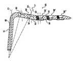
- FIG. 1is an illustrative embodiment of a bone plate attached to a bone F having a fracture f;
- FIG. 2is a top view of a portion of the bone plate of FIG. 1 ;
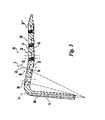
- FIG. 3is a cross-sectional view of the bone plate of FIG. 1 taken along the line III—III in FIG. 2 ;
- FIG. 4is an illustrative embodiment of a bone plate hole
- FIG. 5is a cross-sectional view of another illustrative embodiment of bone plate holes
- FIG. 6is cross-sectional view of the bone plate hole in FIG. 5 taken along the line VI—VI;
- FIG. 7is another cross-sectional view of another illustrative embodiment of bone plate holes
- FIG. 8is cross-sectional view of the bone plate hole in FIG. 7 taken along the line VIII—VIII;
- FIG. 9is another cross-sectional view of another illustrative embodiment of bone plate holes.
- FIG. 10is a top-view of the bone plate hole of FIG. 9 ;
- FIG. 11is a cross-sectional view of the bone plate hole of FIG. 9 taken along the line XI—XI;
- FIG. 12is a cross-sectional view of the bone plate hole of FIG. 9 taken along the line XII—XII;
- FIG. 13is a plan view of an illustrative embodiment of a portion of the bone plate of FIG. 1 ;
- FIG. 14is a cross-sectional view of the portion of the bone plate of FIG. 14 taken along the line XIV—XIV;
- FIG. 15is an illustrative embodiment of a bone anchor
- FIG. 16is another illustrative embodiment of a bone anchor.
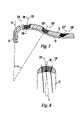
- FIG. 17is a side elevation view of yet another bone plate according to a preferred embodiment of the invention, showing at least one bone anchor contacting a blade portion of the bone plate.
- FIG. 1Shown in FIG. 1 is a first illustrative embodiment of bone plate 10 for use in internal fixation, compression and/or distraction of a bone, for example, the proximal portion of femur F, having a fracture f.
- a bonefor example, the proximal portion of femur F, having a fracture f.
- One of ordinary skill in the artwill know and appreciate, however, that the principles of the present invention may be applied to bone plates for fixation of other bones of humans and/or animals, such as, for example, long bones including the tibia, humerous, fibula, radius, ulna and for different parts or portions of long bones (e.g., the distal femur).
- Bone plate 10includes a first portion 12 that is configured to lie substantially parallel to the surface of bone F anchored by a plurality of bone anchors 100 , 110 , 120 .
- first portion 12is substantially elongated and, preferably, substantially straight, as illustrated in FIG. 1 .
- the elongated plate portion 12includes an upper surface 16 and a lower or bone surface 18 .
- the bottom or lower surface 18may be curved to better conform to the bone to which it is intended to attach.
- the upper surface 16may also be curved or contoured.
- the width of the first portion 12may be substantially uniform and may range from approximately 8 millimeters (mm) to approximately 24 mm and is more preferably about 12 mm to about 20 mm.
- the thickness of the platemay generally range from about 4 mm to about 12 mm, and, more preferably, about 6 mm to about 9 mm.
- the bone plate illustrated in FIG. 1has a thickness of approximately 7 mm to about 8 mm.
- the length of bone platemay vary, with exemplary lengths ranging from about 60 mm to about 150 mm, and more preferably about 80 mm to about 120 mm.
- the bone plate of FIG. 1has a length of about 100 mm to about 105 mm.
- the first portion 12may be anchored such that the lower surface 18 of first portion 12 contacts the bone F directly, or alternatively, the first portion 12 may be held at a distance from the bone surface. Keeping bone plate 10 from contacting the bone may facilitate increased blood flow over the fracture zone.
- Bone plate 10further includes a second portion 14 configured to be inserted and anchored into bone tissue, for example, the condyle of bone F as shown in FIG. 1 .
- the second portion 14forms a blade insertable in the condyle to lag or attach the bone plate 10 to the bone F.
- the second portion 14also includes an upper surface 20 and lower surface 22 .
- bone plate 10is made from a single piece of material such that first portion 12 and second portion 14 are integral with one another; alternatively, first portion 12 and second portion 14 may be joined together by means known to those of ordinary skill in the art.
- second portion 14is oriented with respect to first portion 12 such that the lower surface 22 and lower surface 18 form an included angle ⁇ .
- angle ⁇ranges from about 75° to about 150° and more preferably may range from about 145° to about 120°, or from about 75° to about 110° depending upon its application. In FIG. 1 the angle is between 81° and about 95° for bone plate 10 in which blade portion 14 is inserted into the condyle.
- Bone plate 10may optionally include a third portion 24 having upper surface 26 and a lower surface 28 .
- Third portion 24may be bent or angled with respect to the second portion 14 such that the lower surface 28 and lower surface 22 of blade portion 14 form an included angle ⁇ , wherein ⁇ ranges from approximately 75° to approximately 85° and preferably is about 81°.
- Angle ⁇is different than and preferably less than angle ⁇ .
- the degree of bending between the first portion 12 and third portion 24will vary depending upon the application of the plate but may vary between an angle ⁇ of about 0° and about 25° and, more preferably, may vary from about 14° to about 16°.
- third and first portions 12 , 24may be configured and integrated such that their lower surfaces 18 , 28 define a single lower surface at a single relative angle ⁇ with respect to lower surface 22 of second portion 14 .
- Third portion 24is preferably integrated with first portion 12 and second portion 14 .
- Third portion 24is attached by a plurality of bone anchors 100 , 110 .
- third portion 24is substantially elongated and may be configured such that the third portion 24 may be anchored such that the lower surface 28 contacts bone F directly, or alternatively third portion 24 may be held at a distance from the bone surface.
- the third portion 24can be substantially arcuate having a constant radius of curvature or a radius of curvature that varies over its length.
- the third portion 24may include one or more relatively straight sections.
- the relatively straight sectionsmay be connected by other segments having a radius of curvature.
- the third portion 24has a straight section 27 connected to the first portion 12 with a radius of curvature R 1 of about 95 mm and connected to the second portion 14 with a radius of curvature R 2 of about 90 mm.
- the radius of curvature R 1 and R 2may vary from exemplary values from about 30 mm to about 150 mm depending upon the application of the bone plate.
- the radius of curvature R 1 , R 2can also vary outside the exemplary range.
- FIG. 2shows a plan view of upper surface 16 of integrated first elongated plate portion 12 and optional third portion 24 .
- Elongated plate portion 12 and optional portion 24define a longitudinal axis 29 and includes a plurality of bone plate holes 30 for receiving a bone anchor, for example bone screw 100 , to anchor bone plate 10 to the surface of bone F.
- a bone anchorfor example bone screw 100
- the bone anchor 100 , 110 , 120may be in the form of a bone screw having a head and a threaded shank (for example any one of the types shown in FIGS. 15–16 )
- other bone anchors known to one of ordinary skill in the art, such as blades, nails, pins, etc.may be used. Referring to FIGS.
- bone screw 100has a central axis 101 , a shaft in the form of a threaded shank 104 , a tip 105 , and a threaded head 102
- bone screw 110similarly has a central axis 111 , a threaded shank 114 , and a tip 115
- bone screw 110has a partially spherical head 112 without threads.
- Other geometries and configurationsare possible for the bone screw.
- Either of bone screws 100 , 110 , 120may be constructed from, for example, titanium, alloys of titanium, stainless steel, resorbable materials such as polymers, allograft or other biocompatible materials known in the art.
- Bone screws 100 , 110 , 120are preferably compatible with the bone plate 10 in terms of composition and strength. Bone screws 100 , 110 , 120 may be cannulated, as shown in FIG. 16 with a through bore or channel 117 extending from the head 112 to the tip 115 , for introducing instruments, for example, a guide wire.
- elongated plate portion 12may include second, third, fourth and fifth holes or as many holes 30 , 30 ′, 30 ′′, etc. as is necessary, but usually at least two holes 30 , to effectively anchor bone plate 10 or perform compression and distraction of bone F about the fracture site or both.
- the holes of elongated plate portion 12 , and optional third portion 24may take many different forms, and may be substantially aligned along longitudinal central axis 29 or alternatively, any one of holes 30 may be offset laterally to either side of or aligned with longitudinal central axis 29 .
- FIG. 3illustrates a preferred embodiment of bone plate 10 which includes a plurality of holes 30 located in optional third portion 24 , in this case two holes 30 , and a plurality of bone plate holes 30 ′, 30 ′′, 30 ′′′ in this case three holes 30 ′, 30 ′′, 30 ′′′ located in first portion 12 .
- bone plate holes 30 ′, 30 ′′, 30 ′′′may be different, in FIG. 3 they are substantially the same and will be described with reference to bone plate hole 30 ′ for ease of reference.
- Bone plate hole 30 ′may be substantially the same as bone plate holes 30 or preferably may be configured to be substantially the same as bone plate holes 330 described in reference to FIGS. 9–12 .
- Bone plate holes 30are preferably aligned along the longitudinal central axis 29 as illustrated in FIG. 2 , however, bone plate holes 30 may be offset from longitudinal central axis 29 . Bone plate holes 30 may be offset on the same side of the central axis 29 , on different sides, or one or more bone plate holes 30 may be aligned with the longitudinal central axis 29 while one or more bone plate holes are offset from central axis 29 .
- One or more bone plate holes 30 ′ in the first portion 12may be aligned with the central axis 29 or laterally offset on the same side or different sides of the central axis 29 .
- the bone plate holes 30 ′may be offset on either side or the same side as the central axis 29 .
- the bone plate holes 30 ′may be arranged in any combination of aligned or offset configurations.
- the bone plate holes 30 ′may have the central axis of one hole 30 ′ aligned with the central axis 29 and the central axis of the other two holes 30 ′ offset on a different side of the axis.
- the central axis of the holes 30 ′may be offset any distance from the central axis but are preferably offset from about 0 to about 4 mm from the central axis and more preferably about 1 mm to about 2 mm.
- the holes 30 ′ in bone plate 10 shown in FIG. 3are offset approximately 1.6 mm.
- FIGS. 4 and 5Shown in FIGS. 4 and 5 is a first illustrative embodiment of bone plate hole 30 having a first hole portion 32 and second hole portion 34 overlapping and in communication with the first hole portion 32 .
- First hole portion 32defines a central axis 33 and may have a first counterbore 36 along the upper surface 26 and second counterbore 38 along the lower surface 28 .
- the first counterbore 36 and the second counterbore 38are substantially smooth.
- the second hole portion 34may also define a second central axis 35 and include first counterbore 37 and second counterbore 39 along upper and lower surfaces 26 , 28 respectively.
- second central axis 35may be angled with respect to first central axis 33 at an angle ⁇ , which may preferably range from about 10° to about 35°, and, more preferably, from about 16° to about 28°.
- First central axis 33 of first hole portion 32may be oriented substantially perpendicular to at least a portion of the lower surface 18 which may lie substantially parallel to the surface of bone F.
- First counterbore 36may be configured to engage the head of a bone anchor 110 .
- Counterbore 36may be configured so as to align the shank of bone screw 110 substantially along the first central axis 33 .
- counterbore 36is substantially smooth and also partially spherical, as is shown in FIG. 5 and FIG.
- a bone screw 110 having a spherical head 112may be inserted and oriented at a surgeon selected angle with respect to first counterbore 36 so as to apply compressive or distraction forces about the fracture f upon engagement of the spherical head 112 with the first counterbore 36 .
- the second hole portion 34may be configured and the second central axis 35 may be angled so that upon receiving a bone anchor, for example, bone anchor 110 of the type shown in FIG. 15 , the shank 114 of bone anchor 110 is substantially aligned along the second central axis 35 in an angled relationship with respect to blade portion 14 having longitudinal axis 15 . More specifically, second hole portion 34 may be configured such that the second central axis 35 and the longitudinal axis 15 of blade portion 14 intersect at a point below the lower surface 18 to define a plane.
- the second counterbore 39is conically tapered so that its width decreases from the first counterbore 37 to the lower surface 28 .
- the second counterbore 39is preferably threaded or at least partially threaded.
- the threadmay partially or fully extend from upper surface 26 to lower surface 28 .
- Preferably the threadextends along the periphery of the second counterbore from about 190° to about 280°.
- a screwsuch as screw 200 shown in FIG. 15 inserted into the second portion 34 of bone plate hole 30 will be threaded into the bone plate 10 and fixed into an angular position such that it is locked with the bone plate so that axis 101 will substantially coincide with axis 35 of the second hole portion 34 .
- Bone plate hole 30may be the same as or similar to the bone plate hole described in U.S. Pat. No. 6,669,701 which disclosure and description is incorporated herein by reference.
- At least one of the bone plate holes 30is provided in the plate portion 24 and is configured so as to receive a bone anchor such that the shaft of the shank is directed towards and angled with respect to the blade portion 14 thereby forming a truss or substantially rigid construct to improve anchorage of bone plate 10 in bone F.
- the trussimproves the anchorage by distributing loads and stresses experienced at the interface of the anchor and perimeter of the hole in the base plate.
- the bone anchor 100 , 110may be selected of such a length so as to contact or nearly contact the lower surface 22 of blade portion 14 , as shown in FIG. 17 .
- bone anchor 110 received in the second hole portion 54may contact or nearly contact blade portion 14 anywhere along the length of the lower surface 22 .
- the bone plate 10may be provided with any number of bone plate holes each configured to receive and direct a bone anchor in any manner relative to the blade portion 14 or one another so as to produce a rigid stable construct for fixation, compression or distraction of bone F.
- Orientation of any bone anchor 100 , 110 , 120 engaged with bone plate 10 , relative to the first, second and third bone plate portions 12 , 14 , 24is facilitated by the configuration of bone plate hole 30 , 30 ′, and the bone plate holes 230 , 230 ′, 230 ′′, 330 which are described in greater detail below.
- the second hole portion 34 of each additional hole 30may be variably configured so as to angle the second central axes 35 of each hole 30 relative to the blade portion 14 in a manner that produces the desired stable fixation.
- the second central axis 35 of each hole 30will be configured to intersect the longitudinal axis 15 of blade portion 14 at a point below lower surface 18 .
- Each additional bone anchor received in each additional second hole portion 34 and aligned with second central axis 35may form a truss with and support blade portion 14 .
- Each additional bone anchormay contact or nearly contact blade portion 14 or other bone anchor at a point below the lower surface 18 , 28 .
- the bone anchorsmay contact or nearly contact blade portion 14 anywhere along its length or the length of a different bone anchor.
- second counterbore 38 of first hole portion 32may be substantially cylindrical having a constant diameter from lower surface 28 until first counterbore 36 .
- first or second hole portions 32 , 34may include a portion that conically tapers so that the diameter of the partial hole decreases in the direction toward lower surface 28 .
- first hole portion 32 or second hole portion 34 or bothmay have a portion of their periphery threaded for engagement with a threaded shank or the threaded head of a bone anchor, for example, the bone anchor 100 shown in FIG. 15 , in order to threadedly lock the bone anchor 100 in a fixed angular relationship relative to the first bone plate portion 12 and third bone plate portion 24 .
- first or second portions 32 , 34may include smooth portions.
- first hole portion 32is substantially smooth and elongated while second hole portion is circular and threaded at least partially around its periphery.
- second hole portion 34is threaded from about 190° to about 280°.
- Any bone plate hole 30 , 30 ′ of bone plate 10may be configured in a manner substantially similar to the bone plate holes disclosed in U.S. Pat. No. 6,669,701 which is incorporated herein by reference thereto.
- FIGS. 7 and 8Shown in FIGS. 7 and 8 is an illustrative embodiment of bone plate hole 230 .
- Hole 230may be located in first portion 12 but preferably in third portion 24 of the bone plate 10 and may contain a central axis 233 along which the shaft of a bone anchor would be substantially aligned and extend.
- bone plate hole 230may be configured such that the central axis 233 may intersect the longitudinal axis 15 of blade portion 14 at a point below the lower surface 18 , lower surface 28 or both.
- a bone anchor having a shank substantially aligned with the central axis 233may form a truss with blade portion 14 for improved anchorage of bone plate 10 .
- the axis 233 , 233 ′, 233 ′′may form an angle w with the axis 15 of the blade portion 14 .
- the angle wmay vary from about 0° to about 45° degrees.
- the angle w in the bone plate shown in FIG. 7 between axis 15 and axis 233is about 5°, between axis 15 and axis 233 ′ is about 30°, and between axis 15 and axis 233 ′′ is about 45°.
- Hole 230may be configured for engaging the head of a bone anchor. More preferably, hole 230 may be configured for fixing and locking the bone anchor in a fixed and predetermined orientation with respect to the blade portion 14 or the exterior surface of the bone F into which the anchor is inserted, for example, by threaded, interference or press fitted engagement, or any other form of engaging the head of bone anchor with plate hole 230 along a predetermined and fixed axis as would be known to one of ordinary skill in the art. In the illustrative embodiment shown in FIG. 7 , hole 230 is threaded for respective engagement, with bone anchors, for example bone anchor 100 of FIG. 15 having threaded head 102 . As seen in FIG.
- threaded hole 230may be conically tapered so that its diameter decreases in a direction toward the lower surface 18 of bone plate 10 .
- the tapering of hole 230may facilitate alignment between the threads of hole 230 and the threads on the head 102 of bone screw 100 .
- threaded hole 230may be substantially cylindrical, partially spherical or other shapes known in the art.
- the central axis 233 of hole 230may define an angle ⁇ relative to a plane that includes longitudinal axis 29 and substantially bisects the bone plate 10 .
- the angle ⁇may vary from about 0° to about 10° although other variations and angles are possible.
- the threaded engagement of the bone plate hole 230 and the threaded head 102prevents movement of bone plate 10 with respect to bone screw 100 and locks the angular position of the threaded shank 104 relative to the blade portion 14 .
- bone plate 10With the threaded shank 104 of a bone screw 100 anchored to the fractured bone f and the threaded head 102 lockingly engaged with the threaded hole 230 , bone plate 10 is fixed to the bone F, and depending on the depth with which the threaded shank 104 is inserted into the bone, the lower surface 18 of the bone plate 10 may directly contact the bone surface, similar to the configuration shown in FIG. 1 , or alternatively, bone plate 10 may be affixed and spaced at a distance from the bone surface.
- the hole 230may be configured so as to align the shank 104 at such an angle with respect to the elongated plate portion 12 so as to reduce the gap of the fracture f upon locking of the threaded head 106 in the threaded hole 230 .
- bone plate 10may be provided with as many bone plate holes as are required for the surgical procedure. Accordingly, bone plate 10 may be provided with a plurality of bone plate holes configured as hole 230 . Each hole may be configured as described above but vary by the angle of orientation w relative to the blade portion 14 . For example, as is shown in FIG. 7 , bone plate 10 includes first hole 230 having central axis 233 , and bone plate 10 additionally includes second and third holes 230 ′, 230 ′′ having central axes 233 ′ and 233 ′′ respectively.
- First, second and third holes 230 , 230 ′, and 230 ′′are spaced relative to one another in the direction of elongation of plate 10 , and each is threaded and conically tapered in the direction from upper surface 16 to lower surface 18 .
- the angle of their respective central axes 233 , 233 ′ and 233 ′′ of the three holes 230 , 230 ′ and 230 ′′ relative to the blade portion 14may vary for each axes.
- each bone anchor received and threadably located in holes 230 , 230 ′, and 230 ′′is threadedly aligned with central axes 233 , 233 ′ and 233 ′′ and may form a truss with blade portion 14 as previously described with respect to bone hole 30 .
- any one of holes 230 , 230 ′ and 230 ′′may be configured such that its central axis intersects the central axis of another bone plate hole provided on plate 10 operatively associating the two bone anchors received therein.
- an anchor received in hole 230 , 230 ′ and 230 ′′ configured as described abovemay contact or nearly contact another bone anchor received in a bone plate hole 30 or 30 ′ located on bone plate 10 .
- the bone anchorsmay contact or nearly contact at the tip or any other point along the shanks of the bone anchors.
- Bone plate 10may preferably be alternatively configured with one or more combination holes 330 shown in FIGS. 9 and 10 .
- Combination hole 330may contain a first hole portion 320 and a second hole portion 340 , in which the second hole portion 340 overlaps and is in communication with the first hole portion 320 .
- the second hole portionmay overlap and be in communication with the first hole portion 32 from upper surface 16 to lower surface 18 .
- First hole portion 320may preferably be elongated in the direction of the longitudinal axis 29 of bone plate 10 .
- the first hole portionmay be elongated in a direction that is transverse to the longitudinal axis 29 of the bone plate 10 . While the axis 329 of the elongated first hole portion 320 is shown in FIG.
- First hole portion 320may define a first central axis 333 and preferably includes a first counterbore 360 along the upper surface 16 and a second counterbore 380 along the lower surface 18 .
- first counterbore 360may preferably be substantially smooth and spherical for engagement with a bone anchor having a spherical head, for example, head 112 of bone screw 110 in FIG. 16 .
- Bone screw 110may be received in first hole portion 320 such that the spherical head 112 engages first counterbore 360 so as to bias the bone plate 10 to provide compression or distraction of the bone fracture f.
- Second counterbore 380may be similarly preferably spherical to facilitate angled reception of bone anchor 110 in first hole portion 320 or second counterbore 380 may be substantially partially cylindrical.
- second hole portion 340may preferably be substantially circular defining a second central axis 350 which may preferably be substantially parallel to axis 333 .
- Second hole portionmay similarly include a first counterbore 370 along the upper surface 16 and a second counterbore 390 along the lower surface 18 .
- Second hole portion 340may preferably define along a portion of its periphery a screw thread 342 for threadedly locking a bone anchor in a fixed angled relationship relative to the elongated plate portion 12 .
- the thread 342may extend along the periphery relative to central axis 350 at an angle from about 190° to about 280°.
- Screw thread 342may preferably be engaged by the threaded head portion 102 of bone screw 100 , for example, shown in FIG. 15 .
- Screw thread 342may be disposed in a single plane or in several planes. The planes(s) may be parallel to upper surface 16 and/or to lower surface 18 . Alternatively, the planes may be angled relative to the upper surface 16 or the lower surface 18 in order to angle a bone anchor relative to the at least a portion of the bone plate 10 . As seen in FIG. 11 , thread 342 may preferably substantially extend from upper surface 16 to lower surface 18 of bone plate 10 , and second hole portion 340 may preferably conically taper from upper surface 16 to lower surface 18 . Referring back to FIG.
- bone plate 10is shown having at least three holes configured substantially similarly to hole 330 .
- second hole portion 340may be angled relative to upper surface 16 and/or lower surface 18 , such that a bone anchor, for example bone screw 100 , received in second hole portion 340 is acutely angled relative to at least a portion of bone plate 10 .
- bone hole 230may be located on bone plate 10 with second central axis 350 intersecting longitudinal axis 15 of blade portion 14 at a point below the lower surface 18 , such that bone anchor 100 is threadably received in second hole portion 340 in a fixed and locked relationship relative to blade portion 14 .
- shank 104 of bone screw 100may be directed toward blade portion 14 of plate 10 so as to form a truss in a manner substantially similar to the truss described above.
- Bone plate holes configured as holes 30 , 30 ′, 230 , 330may be located anywhere along elongated plate portion 12 of bone plate 10 such that the central axes 333 and 350 intersect and align with the longitudinal axis 29 of bone plate 10 , or alternatively, the holes 30 , 30 ′, 230 , 330 may be located along elongated plate portion 12 such that either central axis 333 or 350 is spaced relative to the longitudinal axis 29 of bone plate 10 .
- blade portion 14 of bone plate 10is shown having a longitudinal axis 15 , a proximal end 62 adjacent elongated plate portion 12 , and a distal portion 64 .
- the width at the distal end 64preferably tapers in the direction toward the distal end 64 .
- the upper surface 20may include at least one channel 66 running longitudinally defined by at least one side wall 69 , the channels thereby minimizing the amount of bone removal required to anchor bone plate 10 and preserving the blood supply throughout the fracture site.
- the channel 66may be of uniform depth extending from proximal end 62 to distal end 64 , or preferably the depth of channel 64 may vary, increasing from proximal end 62 to distal end 64 so that the thickness of the blade portion in the channel is greatest at the proximal end 62 .
- Blade portion 14preferably has two channels 66 formed by side walls 69 and central wall 70 . Although FIG. 13 shows two channels 66 included in blade portion 14 , any number of channels may be provided as are needed and as are possible across the width of blade portion 14 .
- blade portion 14may also include a cannulation or bore 68 running from proximal end 62 to distal end 64 .
- the bore 68preferably is located in the central wall 70 .
- Bore 68may be dimensioned and configured to receive a guide wire therethrough.
- the space for the blade portion 14is prepared by the surgeon using a chisel as known in the art.
- the blade portion 14may then be located and placed over the guide wire such that the guide wire is received in the bore 68 .
- the plate 10may then be anchored to the bone F.
- bone plate 10may include any where along its length additional bores or cannulations configured and dimensioned to receive guide wires for facilitating location of bone plate 10 along fractured bone F.
- Bone plate 10may be constructed from biocompatible materials such as, for example, titanium, titanium alloys, stainless steel, ceramics, resorbable materials, and allograft, although one of ordinary skill in the art will know and appreciate that any biocompatible material may be used.
- the bone plate 10may also be coated with various substances including, for example microbial agents, antibiotics, and/or growth factors including coatings that contain such substances.
Landscapes
- Health & Medical Sciences (AREA)
- Orthopedic Medicine & Surgery (AREA)
- Life Sciences & Earth Sciences (AREA)
- Surgery (AREA)
- Medical Informatics (AREA)
- General Health & Medical Sciences (AREA)
- Biomedical Technology (AREA)
- Heart & Thoracic Surgery (AREA)
- Nuclear Medicine, Radiotherapy & Molecular Imaging (AREA)
- Molecular Biology (AREA)
- Animal Behavior & Ethology (AREA)
- Engineering & Computer Science (AREA)
- Public Health (AREA)
- Veterinary Medicine (AREA)
- Neurology (AREA)
- Surgical Instruments (AREA)
- Prostheses (AREA)
- Polishing Bodies And Polishing Tools (AREA)
- Materials For Photolithography (AREA)
Abstract
Description
The present invention relates generally to bone plates, and more specifically, to bone plates having a blade portion for the fixation of fractured bone, preferably long bones, including the femur and the tibia.
A bone plate is a plate that is fastenable to the surface of a fractured bone to support and/or stabilize the fracture as the bone heals. Bone plates may be attached to the bone with bone screws that extend from the plate into the bone. In some examples, the head of the bone screw is locked to the plate (e.g., by threaded engagement between the screw head and the bone plate) and in other plates the head of the screw is free to angulate with respect to the plate, such that the screw may be placed in the bone at a surgeon-selected angle. In yet other examples, the screw head may cooperate with the bone plate to provide compression or distraction of the fracture (i.e., to push the bone fragments towards or away from one another).
When treating certain types of fractures, such as that of the proximal portion of the femur, there may be high stresses at the bone-screw and/or screw-plate interfaces. Several different types of bone plates have been developed to accommodate these high stresses. In one example, sometimes referred to as a “blade plate,” the bone plate may have a blade-shaped portion that extends approximately perpendicularly to the plate, and extends into a channel formed in the bone through the fracture site. In another example, a lag screw may extend from a barrel portion of the plate and through the fracture site. However these additional structures, for example the blade-shaped portion, may require additional support due to the redistribution of stresses from the loads experienced throughout the remainder of the bone plate.
The present invention is directed to a bone plate for fixation of a fractured bone. In one embodiment, the bone plate may comprise a first plate portion having a first longitudinal axis, an upper surface and a lower surface and a second plate portion having a second longitudinal axis, an upper surface and a lower surface. The second plate portion may be angled with respect to the first plate portion such that the lower surface of the first plate portion and the lower surface of the second plate portion define a first included angle therebetween. The first portion of the bone plate may have at least one hole for receiving a bone anchor having a shaft, the hole having a first hole portion defining a first central axis substantially perpendicular to the lower surface and a second hole portion overlapping and in communication with the first hole portion from upper to lower surface and defining a second central axis substantially angled with respect to the first central axis. The second hole portion of the bone plate may be configured to receive a bone anchor such that the shaft of the bone anchor is not substantially perpendicular with respect to the first portion of the bone plate. The second portion of the bone plate may be a blade having a proximal end adjacent the first portion of the bone plate and a distal end, the blade configured and adapted so that the distal end is inserted within the interior of the bone. The upper surface of the blade may include at least one channel. The blade may include a bore extending from its proximal end to its distal end, the bore being dimensioned and configured to receive a guide wire. The first included angle between the lower surface of the first portion and the lower surface of the second portion ranges from about 75° to about 150° and, more preferably about 75° to 110° or about 145° to about 120° depending upon the plates application.
The second central axis of the second hole portion of the bone plate may be angled so as to substantially intersect the second longitudinal axis at a point below the lower surface of the first portion of the bone plate. The first longitudinal axis of the bone plate may define a plane that bisects the first portion of the bone plate and the second central axis may intersect the plane at a single point. The second central axis may be angled with respect to the first central axis and the angle may range from about 10° to about 35°. The second hole portion of the bone plate may be configured to receive the bone anchor in a manner so that the shaft is substantially at a fixed angle with respect to the second portion of the bone plate. At least a portion of the second hole portion may be threaded for threadably engaging a threaded head of a bone anchor, the second hole being configured to fix the bone anchor at an angle relative to the second portion of the bone plate. The threaded portion of the second hole portion may extend along the periphery relative to the second central axis at an angle from about 190° to about 280°.
A bone anchor having a threaded head may be supplied which threadably engages with the threaded portion of the second hole portion. The bone anchor may be configured and dimensioned so as to contact at least a portion of the second portion of the bone plate. The first hole portion of the bone plate may be smooth and may be elongated in the direction of the first longitudinal axis. At least a portion of the second hole portion may conically taper from the upper surface to the lower surface. The first hole portion may be elongated in the direction of the first longitudinal axis and may include a first substantially spherical counterbore along the upper surface and a second counterbore along the lower surface of the bone plate. A bone anchor having a spherical head may be supplied and the first counterbore may be configured to engage the spherical head for compression or distraction of the fracture.
The bone plate according to another embodiment may include an elongated plate portion having a first longitudinal axis, an upper surface and a lower surface and a blade portion having a second longitudinal axis, an upper surface and a lower surface, the blade portion being angled with respect to the plate portion. The plate portion may have at least one hole for receiving a bone anchor having a shaft, the hole having a first portion defining a first central axis substantially perpendicular to the lower surface and the hole may include a second portion overlapping and in communication with the first portion and having a second central axis substantially angled with respect to the blade portion. At least a portion of the periphery of the second hole portion may be threaded, the second hole portion being configured to threadably receive the bone anchor such that the shaft is substantially coaxially aligned with the second central axis and threadably and angularly fixed with respect to the blade portion. The portion of the periphery of the second hole portion that is threaded angularly ranges about the second central axis from about 190° to about 280°. The bone anchor may be a bone screw having a threaded shaft and a threaded head. The bone screw may be received in the second portion of the hole so that the threaded shaft is angled with respect to the blade portion so as to form a truss. Preferably the threaded head is engaged with the threaded portion of the periphery of the second portion of the hole so as to lock the bone plate with respect to the bone screw. At least a portion of the second hole portion may conically taper from the upper surface to the lower surface.
The first hole portion may be elongated in the direction of the first longitudinal axis and may include a first substantially spherical counterbore along the upper surface and a second counterbore along the lower surface of the bone plate. The first counterbore may be configured to engage the spherical head for compression or distraction of the fracture. The hole may be located on bone plate such that at least one of the first and second central axes is spaced a distance from the first longitudinal axis of the elongated plate portion.
The bone plate according to another embodiment may comprise an elongated plate portion having a first longitudinal axis, an upper surface and a lower surface and a blade portion having a second longitudinal axis, an upper surface and a lower surface, the blade portion being angled with respect to the plate portion and further being configured to be inserted into the interior of the bone. The plate portion may have at least one threaded hole having a central axis, the hole being configured for threadably receiving a bone anchor having a shaft such that the shaft is substantially aligned along the central axis and the hole is angled relative to the blade portion such that the central axis intersects the second longitudinal axis at a point below the lower surface of the bone plate to form a truss. The threaded hole may conically taper from upper to lower surface. The bone anchor may be a bone screw having a threaded head and a threaded shaft, the bone screw received in the at least one threaded hole such that the threaded head of the bone screw is threadedly engaged with the at least one hole so as to fix the bone plate relative to the bone screw. The bone screw may be a suitable length so that at least a portion of the shaft contacts the blade portion of the bone plate.
The bone plate may comprise at least a second threaded hole spaced relative to the first threaded hole, the second hole having a central axis, the hole being configured for threadedly receiving a bone anchor having a shaft such that the shaft is substantially aligned along the central axis of the second hole, and the second hole may be angled relative to the blade portion such that central axis of the second hole intersects the second longitudinal axis at a point below the lower surface of the bone plate to form a truss. The central axis of the second threaded hole may be angled relative to the central axis of the at least one other threaded hole such that a bone anchor received in the second threaded hole is operatively associated with a bone anchor received in the at least one other threaded hole.
According to another embodiment a bone plate system may be provided which comprises at least one bone anchor having a shaft and a head portion, a bone plate having an elongated plate portion having a first longitudinal axis, an upper surface and a lower surface and a blade portion having a second longitudinal axis, an upper surface and a lower surface, the blade portion being angled with respect to the plate portion so as to define an included angle therebetween ranging between about 75° and about 150°, and, more preferably about 81° to about 95°, the plate portion having at least one hole, the hole having a first portion defining a first central axis and including a first counterbore along the upper surface, the first hole portion being configured to receive the bone anchor such that the head is in sliding engagement with the first counterbore; and the hole includes a second hole portion in communication with the first hole portion from the upper surface to the lower surface and defining a second central axis angled with respect to the blade portion, the second hole portion including a second counterbore, the second hole portion being configured to receive the bone anchor such that the shaft is substantially coaxially aligned with the second central axis and the head portion is fixedly engaged with second counterbore.
The second counterbore may be threaded and the head portion of at least one bone anchor may be threaded, the second counterbore being configured for fixed threaded engagement with the head portion of the bone anchor. Alternatively, the second counterbore may be smooth and the head portion of the at least one bone anchor may be threaded. Alternatively still, the second counterbore may be threaded and the head portion of the bore anchor may be smooth. Still further, the second counterbore may be smooth and the head portion of the bone anchor may be smooth. The first and second central axes may be spaced a distance from the first longitudinal axis. The upper surface of the blade may include at least one channel, and the blade may include a bore extending from proximal to distal end, the bore being dimensioned and configured to receive a guide wire.
The detailed description will be better understood in conjunction with the accompanying drawings, wherein like reference characters represent like elements. It should be understood that the features described in the illustrated drawings may exist singularly or in combination and that the invention is not limited to the embodiment disclosed in the figures which are illustrative only and for the purposes of description and not limitation.
Shown inFIG. 1 is a first illustrative embodiment ofbone plate 10 for use in internal fixation, compression and/or distraction of a bone, for example, the proximal portion of femur F, having a fracture f. One of ordinary skill in the art will know and appreciate, however, that the principles of the present invention may be applied to bone plates for fixation of other bones of humans and/or animals, such as, for example, long bones including the tibia, humerous, fibula, radius, ulna and for different parts or portions of long bones (e.g., the distal femur).
Thethird portion 24 can be substantially arcuate having a constant radius of curvature or a radius of curvature that varies over its length. Alternatively or additionally, thethird portion 24 may include one or more relatively straight sections. The relatively straight sections may be connected by other segments having a radius of curvature. In the embodiment shown inFIG. 1 , thethird portion 24 has astraight section 27 connected to thefirst portion 12 with a radius of curvature R1 of about 95 mm and connected to thesecond portion 14 with a radius of curvature R2 of about 90 mm. The radius of curvature R1 and R2 may vary from exemplary values from about 30 mm to about 150 mm depending upon the application of the bone plate. One of skill in the art will appreciate that the radius of curvature R1, R2 can also vary outside the exemplary range.
Shown inFIG. 2 , elongatedplate portion 12 may include second, third, fourth and fifth holes or asmany holes holes 30, to effectively anchorbone plate 10 or perform compression and distraction of bone F about the fracture site or both. The holes ofelongated plate portion 12, and optionalthird portion 24 may take many different forms, and may be substantially aligned along longitudinalcentral axis 29 or alternatively, any one ofholes 30 may be offset laterally to either side of or aligned with longitudinalcentral axis 29.
One or more bone plate holes30′ in thefirst portion 12 may be aligned with thecentral axis 29 or laterally offset on the same side or different sides of thecentral axis 29. The bone plate holes30′ may be offset on either side or the same side as thecentral axis 29. Thus, the bone plate holes30′ may be arranged in any combination of aligned or offset configurations. In the preferred configuration shown inFIG. 2 , the bone plate holes30′ may have the central axis of onehole 30′ aligned with thecentral axis 29 and the central axis of the other twoholes 30′ offset on a different side of the axis. The central axis of theholes 30′ may be offset any distance from the central axis but are preferably offset from about 0 to about 4 mm from the central axis and more preferably about 1 mm to about 2 mm. Theholes 30′ inbone plate 10 shown inFIG. 3 are offset approximately 1.6 mm.
Shown inFIGS. 4 and 5 is a first illustrative embodiment ofbone plate hole 30 having afirst hole portion 32 andsecond hole portion 34 overlapping and in communication with thefirst hole portion 32.First hole portion 32 defines acentral axis 33 and may have afirst counterbore 36 along theupper surface 26 andsecond counterbore 38 along thelower surface 28. Preferably, thefirst counterbore 36 and thesecond counterbore 38 are substantially smooth. Thesecond hole portion 34 may also define a secondcentral axis 35 and includefirst counterbore 37 andsecond counterbore 39 along upper andlower surfaces FIG. 3 , secondcentral axis 35 may be angled with respect to firstcentral axis 33 at an angle λ, which may preferably range from about 10° to about 35°, and, more preferably, from about 16° to about 28°.
Firstcentral axis 33 offirst hole portion 32 may be oriented substantially perpendicular to at least a portion of thelower surface 18 which may lie substantially parallel to the surface of bone F. First counterbore36 may be configured to engage the head of abone anchor 110.Counterbore 36 may be configured so as to align the shank ofbone screw 110 substantially along the firstcentral axis 33. Preferably,counterbore 36 is substantially smooth and also partially spherical, as is shown inFIG. 5 andFIG. 6 , and abone screw 110 having aspherical head 112 may be inserted and oriented at a surgeon selected angle with respect tofirst counterbore 36 so as to apply compressive or distraction forces about the fracture f upon engagement of thespherical head 112 with thefirst counterbore 36.
Referring again toFIG. 3 , thesecond hole portion 34 may be configured and the secondcentral axis 35 may be angled so that upon receiving a bone anchor, for example,bone anchor 110 of the type shown inFIG. 15 , theshank 114 ofbone anchor 110 is substantially aligned along the secondcentral axis 35 in an angled relationship with respect toblade portion 14 havinglongitudinal axis 15. More specifically,second hole portion 34 may be configured such that the secondcentral axis 35 and thelongitudinal axis 15 ofblade portion 14 intersect at a point below thelower surface 18 to define a plane. Preferably thesecond counterbore 39 is conically tapered so that its width decreases from thefirst counterbore 37 to thelower surface 28. In addition, thesecond counterbore 39 is preferably threaded or at least partially threaded. The thread may partially or fully extend fromupper surface 26 tolower surface 28. Preferably the thread extends along the periphery of the second counterbore from about 190° to about 280°. In this manner, a screw such as screw200 shown inFIG. 15 inserted into thesecond portion 34 ofbone plate hole 30 will be threaded into thebone plate 10 and fixed into an angular position such that it is locked with the bone plate so thataxis 101 will substantially coincide withaxis 35 of thesecond hole portion 34.Bone plate hole 30 may be the same as or similar to the bone plate hole described in U.S. Pat. No. 6,669,701 which disclosure and description is incorporated herein by reference.
Referring again toFIG. 1 , in a preferred embodiment, at least one of the bone plate holes30, is provided in theplate portion 24 and is configured so as to receive a bone anchor such that the shaft of the shank is directed towards and angled with respect to theblade portion 14 thereby forming a truss or substantially rigid construct to improve anchorage ofbone plate 10 in bone F. The truss improves the anchorage by distributing loads and stresses experienced at the interface of the anchor and perimeter of the hole in the base plate. In addition, thebone anchor lower surface 22 ofblade portion 14, as shown inFIG. 17 . Wherebone anchor 110 is of sufficient length,bone anchor 110 received in the second hole portion54 may contact or nearlycontact blade portion 14 anywhere along the length of thelower surface 22. Thebone plate 10 may be provided with any number of bone plate holes each configured to receive and direct a bone anchor in any manner relative to theblade portion 14 or one another so as to produce a rigid stable construct for fixation, compression or distraction of bone F. Orientation of anybone anchor bone plate 10, relative to the first, second and thirdbone plate portions bone plate hole
As additional bone holes30 are added as needed toelongated plate portion 12, thesecond hole portion 34 of eachadditional hole 30 may be variably configured so as to angle the secondcentral axes 35 of eachhole 30 relative to theblade portion 14 in a manner that produces the desired stable fixation. Preferably, the secondcentral axis 35 of eachhole 30 will be configured to intersect thelongitudinal axis 15 ofblade portion 14 at a point belowlower surface 18. Each additional bone anchor received in each additionalsecond hole portion 34 and aligned with secondcentral axis 35 may form a truss with andsupport blade portion 14. Each additional bone anchor may contact or nearlycontact blade portion 14 or other bone anchor at a point below thelower surface contact blade portion 14 anywhere along its length or the length of a different bone anchor.
As seen inFIG. 6 ,second counterbore 38 offirst hole portion 32 may be substantially cylindrical having a constant diameter fromlower surface 28 untilfirst counterbore 36. Alternatively, either first orsecond hole portions lower surface 28. In addition, eitherfirst hole portion 32 orsecond hole portion 34 or both may have a portion of their periphery threaded for engagement with a threaded shank or the threaded head of a bone anchor, for example, thebone anchor 100 shown inFIG. 15 , in order to threadedly lock thebone anchor 100 in a fixed angular relationship relative to the firstbone plate portion 12 and thirdbone plate portion 24. The thread or threads may partially or fully extend from upper tolower surface second portions central axis 33 offirst hole portion 32 intersects the longitudinalcentral axis 29 ofbone plate 10, a plane may be defined common to bothaxes bone plate 10. Preferablyfirst hole portion 32 is substantially smooth and elongated while second hole portion is circular and threaded at least partially around its periphery. Preferablysecond hole portion 34 is threaded from about 190° to about 280°. Anybone plate hole bone plate 10 may be configured in a manner substantially similar to the bone plate holes disclosed in U.S. Pat. No. 6,669,701 which is incorporated herein by reference thereto.
Shown inFIGS. 7 and 8 is an illustrative embodiment ofbone plate hole 230.Hole 230 may be located infirst portion 12 but preferably inthird portion 24 of thebone plate 10 and may contain acentral axis 233 along which the shaft of a bone anchor would be substantially aligned and extend. Moreover,bone plate hole 230 may be configured such that thecentral axis 233 may intersect thelongitudinal axis 15 ofblade portion 14 at a point below thelower surface 18,lower surface 28 or both. Once again, a bone anchor having a shank substantially aligned with thecentral axis 233 may form a truss withblade portion 14 for improved anchorage ofbone plate 10. Theaxis axis 15 of theblade portion 14. The angle w may vary from about 0° to about 45° degrees. The angle w in the bone plate shown inFIG. 7 betweenaxis 15 andaxis 233 is about 5°, betweenaxis 15 andaxis 233′ is about 30°, and betweenaxis 15 andaxis 233″ is about 45°.
The threaded engagement of thebone plate hole 230 and the threadedhead 102 prevents movement ofbone plate 10 with respect tobone screw 100 and locks the angular position of the threadedshank 104 relative to theblade portion 14. With the threadedshank 104 of abone screw 100 anchored to the fractured bone f and the threadedhead 102 lockingly engaged with the threadedhole 230,bone plate 10 is fixed to the bone F, and depending on the depth with which the threadedshank 104 is inserted into the bone, thelower surface 18 of thebone plate 10 may directly contact the bone surface, similar to the configuration shown inFIG. 1 , or alternatively,bone plate 10 may be affixed and spaced at a distance from the bone surface. In addition, when theshank 104 is of sufficient length so as to span across the fracture zone f, thehole 230 may be configured so as to align theshank 104 at such an angle with respect to theelongated plate portion 12 so as to reduce the gap of the fracture f upon locking of the threaded head106 in the threadedhole 230.
As previously explained,bone plate 10 may be provided with as many bone plate holes as are required for the surgical procedure. Accordingly,bone plate 10 may be provided with a plurality of bone plate holes configured ashole 230. Each hole may be configured as described above but vary by the angle of orientation w relative to theblade portion 14. For example, as is shown inFIG. 7 ,bone plate 10 includesfirst hole 230 havingcentral axis 233, andbone plate 10 additionally includes second andthird holes 230′,230″ havingcentral axes 233′ and233″ respectively. First, second andthird holes plate 10, and each is threaded and conically tapered in the direction fromupper surface 16 tolower surface 18. The angle of their respectivecentral axes holes blade portion 14 may vary for each axes. Thus, each bone anchor received and threadably located inholes central axes blade portion 14 as previously described with respect tobone hole 30. In addition, any one ofholes plate 10 operatively associating the two bone anchors received therein. For example, an anchor received inhole bone plate hole bone plate 10. The bone anchors may contact or nearly contact at the tip or any other point along the shanks of the bone anchors.
Referring again toFIGS. 9 and 10 ,second hole portion 340 may preferably be substantially circular defining a secondcentral axis 350 which may preferably be substantially parallel toaxis 333. Second hole portion may similarly include afirst counterbore 370 along theupper surface 16 and asecond counterbore 390 along thelower surface 18.Second hole portion 340 may preferably define along a portion of its periphery ascrew thread 342 for threadedly locking a bone anchor in a fixed angled relationship relative to theelongated plate portion 12. Thethread 342 may extend along the periphery relative tocentral axis 350 at an angle from about 190° to about 280°.Screw thread 342 may preferably be engaged by the threadedhead portion 102 ofbone screw 100, for example, shown inFIG. 15 .Screw thread 342 may be disposed in a single plane or in several planes. The planes(s) may be parallel toupper surface 16 and/or tolower surface 18. Alternatively, the planes may be angled relative to theupper surface 16 or thelower surface 18 in order to angle a bone anchor relative to the at least a portion of thebone plate 10. As seen inFIG. 11 ,thread 342 may preferably substantially extend fromupper surface 16 tolower surface 18 ofbone plate 10, andsecond hole portion 340 may preferably conically taper fromupper surface 16 tolower surface 18. Referring back toFIG. 3 ,bone plate 10 is shown having at least three holes configured substantially similarly tohole 330. In addition,second hole portion 340 may be angled relative toupper surface 16 and/orlower surface 18, such that a bone anchor, forexample bone screw 100, received insecond hole portion 340 is acutely angled relative to at least a portion ofbone plate 10. For example,bone hole 230 may be located onbone plate 10 with secondcentral axis 350 intersectinglongitudinal axis 15 ofblade portion 14 at a point below thelower surface 18, such thatbone anchor 100 is threadably received insecond hole portion 340 in a fixed and locked relationship relative toblade portion 14. As a result,shank 104 ofbone screw 100 may be directed towardblade portion 14 ofplate 10 so as to form a truss in a manner substantially similar to the truss described above.
Bone plate holes configured asholes elongated plate portion 12 ofbone plate 10 such that thecentral axes longitudinal axis 29 ofbone plate 10, or alternatively, theholes elongated plate portion 12 such that eithercentral axis longitudinal axis 29 ofbone plate 10.
Referring now toFIGS. 13 and 14 ,blade portion 14 ofbone plate 10 is shown having alongitudinal axis 15, a proximal end62 adjacentelongated plate portion 12, and adistal portion 64. The width at thedistal end 64 preferably tapers in the direction toward thedistal end 64. Theupper surface 20 may include at least onechannel 66 running longitudinally defined by at least one side wall69, the channels thereby minimizing the amount of bone removal required to anchorbone plate 10 and preserving the blood supply throughout the fracture site. Thechannel 66 may be of uniform depth extending from proximal end62 todistal end 64, or preferably the depth ofchannel 64 may vary, increasing from proximal end62 todistal end 64 so that the thickness of the blade portion in the channel is greatest at the proximal end62.Blade portion 14 preferably has twochannels 66 formed by side walls69 andcentral wall 70. AlthoughFIG. 13 shows twochannels 66 included inblade portion 14, any number of channels may be provided as are needed and as are possible across the width ofblade portion 14.
As shown inFIG. 3 ,blade portion 14 may also include a cannulation or bore68 running from proximal end62 todistal end 64. Thebore 68 preferably is located in thecentral wall 70.Bore 68 may be dimensioned and configured to receive a guide wire therethrough. In some surgical procedures, it may be desirable to precisely locateblade portion 14 by using a guide wire planted in the bone F at the desired point of insertion. Preferably, the space for theblade portion 14 is prepared by the surgeon using a chisel as known in the art. Theblade portion 14 may then be located and placed over the guide wire such that the guide wire is received in thebore 68. Theplate 10 may then be anchored to the bone F. Additionally,bone plate 10 may include any where along its length additional bores or cannulations configured and dimensioned to receive guide wires for facilitating location ofbone plate 10 along fractured bone F.
Further it should be understood that variations and modifications within the spirit and scope of the invention may occur to those skilled in the art to which the invention pertains. Accordingly, all modifications attainable by one versed in the art from the disclosure set forth herein are to be included as further embodiments of the present invention. The scope of the present invention is accordingly defined as set forth in the appended claims.
Claims (32)
1. A bone plate for fixation of a fractured bone, the bone plate comprising:
a first portion having a first longitudinal axis, an upper surface and a lower surface;
a second bladed portion having a second longitudinal axis, an upper surface and a lower surface, the second portion being angled with respect to the first portion such that the lower surface of the first portion and the lower surface of the second portion define a first included angle therebetween;
the first portion having at least one hole for receiving a bone anchor having a shaft, the hole having
a first hole portion defining a first central axis substantially perpendicular to the lower surface at the at least one hole, the first hole portion being configured to receive the bone anchor; and
a second hole portion overlapping and in communication with the first hole portion from upper to lower surface and defining a second central axis angled with respect to the first central axis, at least a portion of the second hole portion being threaded,
wherein the second hole portion is configured to receive the bone anchor in a single, predetermined angular position such that the shaft of the bone anchor is substantially coaxial with the second central axis and non-perpendicular to the lower surface of the first portion of the bone plate at the at least one hole.
2. The bone plate ofclaim 1 , wherein the second central axis of the hole is angled so as to substantially intersect the second longitudinal axis of the bone plate at a point below the lower surface of the first portion of the bone plate.
3. The bone plate ofclaim 1 , wherein the first longitudinal axis defines a plane that bisects the first portion of the bone plate and wherein further the second central axis intersects the plane at a single point.
4. The bone plate ofclaim 1 , wherein the angle between the second central axis and the first central axis ranges from about 10° to about 35°.
5. The bone plate ofclaim 1 , wherein the second hole portion is configured to receive the bone anchor such that the shaft is substantially at a fixed angle with respect to the second portion of the bone plate.
6. The bone plate ofclaim 5 , wherein at least a portion of the second hole portion conically tapers from the upper surface toward the lower surface.
7. The bone plate ofclaim 1 , wherein the threaded portion of the second hole portion angularly ranges about 190° to about 280° along a periphery of the second hole portion about the second central axis.
8. The bone plate ofclaim 1 , further comprising a bone anchor having a threaded head received in the second hole portion, the head threadedly engaged with the threaded portion of the second hole portion, the bone anchor being configured and dimensioned so as to contact at least a portion of the second portion of the bone plate.
9. The bone plate ofclaim 1 , wherein the second bladed portion of the bone plate is configured and adapted to be inserted within the interior of the fractured bone.
10. The bone plate ofclaim 9 , wherein the upper surface of the blade includes at least one channel.
11. The bone plate ofclaim 9 , wherein the blade includes a bore extending from proximal to distal end, the bore being dimensioned and configured to receive a guide wire.
12. The bone plate ofclaim 1 , wherein the first included angle ranges from about 75° to about 110°.
13. The bone plate ofclaim 1 , wherein the first hole portion is smooth and is elongated in the direction of the first longitudinal axis.
14. The bone plate ofclaim 1 , wherein the first hole portion of the at least one hole is elongated in the direction of the first longitudinal axis and includes a first substantially spherical counterbore along the upper surface and a second counterbore along the lower surface of the bone plate, the first hole portion being configured to receive a bone anchor having a spherical head and the first counterbore being configured to engage the spherical head for compression or distraction of the fracture.
15. The bone plate ofclaim 1 , further comprising:
a second hole on the first plate portion, the second hole being threaded and having a central axis A, the second hole further being configured for threadably receiving a bone anchor having a shaft in a predetermined, fixed angular position such that the shaft is substantially aligned along the central axis A; and
a third hole on the first plate portion, the third hole being threaded and having a central axis B, the third hole further being configured for threadably receiving a bone anchor having a shaft in another predetermined, fixed angular position such that the shaft is substantially aligned along the second central axis B of the third hole,
wherein the central axes A, B are angled relative to the second plate portion, angled relative to one another, and substantially non-perpendicular to the lower surface of the first plate portion at the second and third holes, respectively, such that the central axes A, B intersect the second longitudinal axis of the second plate portion at a point below the lower surface of the first plate portion.
16. A bone plate for fixation of a fractured bone, the bone plate comprising:
an elongated plate portion having a first longitudinal axis, an upper surface and a lower surface;
a blade portion configured to be inserted into the interior of the fractured bone, the blade portion having a second longitudinal axis, an upper surface and a lower surface, the blade portion being angled with respect to the plate portion so as to define an included angle therebetween and the upper surface of the blade portion including a plurality of longitudinal channels;
the plate portion having at least one hole for receiving a bone anchor having a shaft, the hole having
a first portion defining a first central axis substantially perpendicular to the lower surface at the at least one hole; and
a second portion overlapping and in communication with the first portion from the upper surface to the lower surface and defining a second central axis angled with respect to the blade portion, the second hole portion having a periphery, at least a portion of the periphery being threaded,
wherein the second hole portion is configured to threadably receive the bone anchor such that the shaft is substantially coaxially aligned with the second central axis, threadably and angularly fixed in a single, predetermined position with respect to the blade portion and non-perpendicular to the lower surface of the plate portion at the at least one hole.
17. The bone plate ofclaim 16 , wherein the thread periphery of the second hole portion angularly ranges about the second central axis from about 190° to about 280°.
18. The bone plate ofclaim 16 , further comprising a bone anchor in the form of a first bone screw having a threaded shaft and a threaded head, the bone screw received in the second portion of the at least one hole, the threaded shaft being angled with respect to the blade portion so as to form a truss, wherein the threaded head is engaged with the threaded portion of the periphery of the second portion of the at least one hole so as to lock the bone plate with respect to the bone screw.
19. The bone plate ofclaim 16 , wherein at least a portion of the second hole portion conically tapers from the upper surface toward the lower surface.
20. The bone plate ofclaim 16 , wherein the first hole portion of the at least one hole is elongated in the direction of the first longitudinal axis and includes a first substantially spherical counterbore along the upper surface and a second counterbore along the lower surface of the bone plate, the first hole portion being configured to receive a bone anchor having a spherical head and the first counterbore being configured to engage the spherical head for compression or distraction of the fracture.
21. The bone plate ofclaim 16 , wherein the at least one hole is located on the bone plate such that at least one of the first and second central axes is spaced relative to the first longitudinal axis of the elongated plate portion.
22. The bone plate ofclaim 21 , further comprising:
a second bone screw having a spherical head; and
a second hole, the second bone screw received in the second hole, the second hole having a first substantially spherical counterbore along the upper surface and a second counterbore along the lower surface of the bone plate, the second bone screw received in the second hole such that the first substantially spherical counterbore is engaged with the spherical head for compression or distraction of the fracture.
23. A bone plate system comprising:
at least one bone anchor having a shaft and a head portion;
a bone plate having an elongated plate portion having a first longitudinal axis, an upper surface and a lower surface and a blade portion having a second longitudinal axis, an upper surface and a lower surface, the blade portion configured to be inserted into the interior of the fractured bone and being angled with respect to the plate portion so as to define an included angle therebetween ranging between about 75° and about 110°;
the plate portion having at least one hole, the hole having
a first portion defining a first central axis and including a first counterbore along the upper surface, the first hole portion being configured to receive the bone anchor such that the head is capable of sliding engagement with the first counterbore; and
a second hole portion in communication with the first hole portion from the upper surface to the lower surface and defining a second central axis angled with respect to the blade portion and non-perpendicular with respect to the elongated plate portion at the at least one hole, the second hole portion including a second counterbore that is at least partially threaded,
wherein the second hole portion is configured to receive the bone anchor in a single, predetermined angular position such that the shaft is substantially coaxially aligned with the second central axis and the head portion is fixedly engaged with the second counterbore.
24. The bone plate system ofclaim 23 , wherein a head portion of at least one bone anchor is threaded, and the second counterbore being is configured for fixed threaded engagement with the head portion of the bone anchor.
25. The bone plate system ofclaim 23 , wherein at least one of the first and second central axes is spaced relative to the first longitudinal axis.
26. The bone plate ofclaim 23 , wherein the upper surface of the blade portion includes at least one channel.
27. The bone plate ofclaim 23 , wherein the blade portion includes a bore extending from proximal to distal end, the bore being dimensioned and configured to receive a guide wire.
28. The bone plate ofclaim 23 , wherein the bone anchor is inserted through the second hole portion and angled with respect to the blade portion so as to form a truss, the bone anchor of such a length that at least a portion of the bone anchor contacts the blade portion of the bone plate.
29. The bone plate ofclaim 23 , further comprising:
a second hole on the plate portion, the second hole being threaded and having a central axis A, the second hole further being configured for threadably receiving a second bone anchor having a shaft in a predetermined, fixed angular position such that the shaft is substantially aligned along the central axis A; and
a third hole on the first plate portion, the third hole being threaded and having a central axis B, the third hole further being configured for threadably receiving a third bone anchor having a shaft in another predetermined, fixed angular position such that the shaft is substantially aligned along the second central axis B of the third hole,
wherein the central axes A, B are angled relative to the blade portion, angled relative to one another, and substantially non-perpendicular to the lower surface of the plate portion at the second and third holes, respectively, such that the central axes A, B intersect the second longitudinal axis of the blade portion at a point below the lower surface of the plate portion.
30. A bone plate for fixation of a fractured bone, the bone plate comprising:
an elongated plate portion having a first longitudinal axis, an upper surface and a lower surface and a blade portion having a second longitudinal axis, an upper surface and a lower surface, the blade portion angled with respect to the plate portion;
at least one hole in the plate portion for receiving a bone anchor having a shaft, the hole having
a first hole portion defining a first central axis substantially perpendicular to the lower surface at the at least one hole, the first hole portion being configured to receive the bone anchor; and
a second hole portion overlapping and in communication with the first hole portion from upper to lower surface and defining a second central axis angled with respect to the first central axis, at least a portion of the second hole portion being threaded,
wherein the second hole portion is configured to receive the bone anchor in a single, predetermined angular position such that the shaft of the bone anchor is substantially coaxial with the second central axis and non-perpendicular to the lower surface of the plate portion at the at least one hole.
31. The bone plate ofclaim 30 , wherein the first hole portion is substantially smooth.
32. The bone plate ofclaim 30 , wherein the angle between the first central axis and the second central axis ranges from about 10° to about 35°.
Priority Applications (12)
| Application Number | Priority Date | Filing Date | Title |
|---|---|---|---|
| US10/874,097US7229445B2 (en) | 2004-06-21 | 2004-06-21 | Bone plate with bladed portion |
| NZ552192ANZ552192A (en) | 2004-06-21 | 2005-06-20 | Bone plate with overlapping holes at differing axis angles in first portion, and second bladed portion |
| JP2007518212AJP5049779B2 (en) | 2004-06-21 | 2005-06-20 | Bone plate |
| AT05771291TATE538738T1 (en) | 2004-06-21 | 2005-06-20 | BONE PLATE |
| CNB2005800277013ACN100542495C (en) | 2004-06-21 | 2005-06-20 | bone plate |
| EP05771291AEP1773218B1 (en) | 2004-06-21 | 2005-06-20 | Bone plate |
| CN200910161030ACN101612059A (en) | 2004-06-21 | 2005-06-20 | Hone lamella |
| ZA200700452AZA200700452B (en) | 2004-06-21 | 2005-06-20 | Bone plate |
| AU2005258088AAU2005258088A1 (en) | 2004-06-21 | 2005-06-20 | Bone plate |
| PCT/US2005/021966WO2006002188A2 (en) | 2004-06-21 | 2005-06-20 | Bone plate |
| CA2571562ACA2571562C (en) | 2004-06-21 | 2005-06-20 | Bone plate |
| KR1020077001299AKR101189725B1 (en) | 2004-06-21 | 2005-06-20 | Bone plate |
Applications Claiming Priority (1)
| Application Number | Priority Date | Filing Date | Title |
|---|---|---|---|
| US10/874,097US7229445B2 (en) | 2004-06-21 | 2004-06-21 | Bone plate with bladed portion |
Publications (2)
| Publication Number | Publication Date |
|---|---|
| US20060004361A1 US20060004361A1 (en) | 2006-01-05 |
| US7229445B2true US7229445B2 (en) | 2007-06-12 |
Family
ID=35514990
Family Applications (1)
| Application Number | Title | Priority Date | Filing Date |
|---|---|---|---|
| US10/874,097Expired - LifetimeUS7229445B2 (en) | 2004-06-21 | 2004-06-21 | Bone plate with bladed portion |
Country Status (11)
| Country | Link |
|---|---|
| US (1) | US7229445B2 (en) |
| EP (1) | EP1773218B1 (en) |
| JP (1) | JP5049779B2 (en) |
| KR (1) | KR101189725B1 (en) |
| CN (2) | CN101612059A (en) |
| AT (1) | ATE538738T1 (en) |
| AU (1) | AU2005258088A1 (en) |
| CA (1) | CA2571562C (en) |
| NZ (1) | NZ552192A (en) |
| WO (1) | WO2006002188A2 (en) |
| ZA (1) | ZA200700452B (en) |
Cited By (68)
| Publication number | Priority date | Publication date | Assignee | Title |
|---|---|---|---|---|
| US20040236337A1 (en)* | 2003-04-02 | 2004-11-25 | Benoist Girard Sas | Greater trochanteric re-attachment device |
| US20060195085A1 (en)* | 2005-02-01 | 2006-08-31 | Inion Ltd. | System and method for stabilizing spine |
| US20070016205A1 (en)* | 2003-10-30 | 2007-01-18 | Florian Beutter | Bone plate |
| US20080119894A1 (en)* | 2004-12-30 | 2008-05-22 | Konigsee Implantate Und Instrumente Zur Osteosynthese Gmbh | Osteosynthesis Plate, E.G. A Plate For The Head Of The Radius Or Humerus, With A Plurality Of Bore Holes For Receiving Bone Screws |
| US20080161860A1 (en)* | 2005-12-23 | 2008-07-03 | Uwe Ahrens | Bone Plate |
| US20080234749A1 (en)* | 2007-01-26 | 2008-09-25 | Zimmer Technology, Inc. | Bone plate providing threaded locking head screw capture |
| US20080249572A1 (en)* | 2004-06-02 | 2008-10-09 | Vineet Dev Tandon | Bone Plate |
| US20090228010A1 (en)* | 2008-03-10 | 2009-09-10 | Eduardo Gonzalez-Hernandez | Bone fixation system |
| US20090275947A1 (en)* | 2008-05-02 | 2009-11-05 | Thomas James Graham | Bone plate system for bone restoration and methods of use thereof |
| US20090275987A1 (en)* | 2008-05-02 | 2009-11-05 | Thomas James Graham | Bone plate extender and extension system for bone restoration and methods of use thereof |
| US20090281577A1 (en)* | 2008-05-08 | 2009-11-12 | Thomas James Graham | Bone plate with reduction aids and methods of use thereof |
| US20100211111A1 (en)* | 2007-09-18 | 2010-08-19 | Stryker Trauma Gmbh | Angularly Stable Fixation Of An Implant |
| US20100217327A1 (en)* | 2009-02-24 | 2010-08-26 | Vancelette David W | Plate and system for lateral treatment of a fracture of the calcaneus |
| US20100274245A1 (en)* | 2003-11-21 | 2010-10-28 | Eduardo Gonzalez-Hernandez | Fracture fixation system |
| US20110009866A1 (en)* | 2009-07-09 | 2011-01-13 | Orthohelix Surgical Designs, Inc. | Osteotomy plate, plate driver and method for their use |
| US20110106081A1 (en)* | 2008-05-08 | 2011-05-05 | Thomas James Graham | Bone Plate with Flange Member and Methods of Use Thereof |
| USD638942S1 (en)* | 2010-01-07 | 2011-05-31 | Zimmer, Inc. | Bone plate fixation device |
| US20110152943A1 (en)* | 2009-12-22 | 2011-06-23 | Eduardo Gonzalez-Hernandez | Bone plate and tool assembly and method for use thereof |
| US20110166573A1 (en)* | 2010-01-07 | 2011-07-07 | Klaus Wenk | Bone plate fixation system |
| USD642685S1 (en)* | 2010-01-07 | 2011-08-02 | Zimmer Gmbh | Bone plate fixation device |
| EP2364658A1 (en) | 2010-03-10 | 2011-09-14 | aap Implantate AG | Bone plate |
| US20110224671A1 (en)* | 2009-09-14 | 2011-09-15 | Kenny Koay | Variable angle compression plate |
| USD648027S1 (en)* | 2010-02-09 | 2011-11-01 | Tornier, Inc. | Prosthesis |
| US20110282393A1 (en)* | 2003-09-29 | 2011-11-17 | Smith & Nephew, Inc. | Bone plate systems using provisional fixation |
| USD655010S1 (en)* | 2011-03-25 | 2012-02-28 | Zimmer, Inc. | Bone plate fixation device |
| US20130006247A1 (en)* | 2011-06-29 | 2013-01-03 | Nextremity Solutions, Llc | Bone plate hybrid device |
| US8469999B2 (en) | 2008-04-17 | 2013-06-25 | Eduardo Gonzalez-Hernandez | Soft tissue attachment system and clip |
| US8591554B2 (en) | 2010-05-07 | 2013-11-26 | Osteomed Llc | System for treating bone fractures |
| US20140148859A1 (en)* | 2012-11-27 | 2014-05-29 | Solana Surgical, Llc | Orthopedic fusion plate and compression screw |
| US8753396B1 (en) | 2010-09-13 | 2014-06-17 | Theken Spine, Llc | Intervertebral implant having back-out prevention feature |
| US8870963B2 (en) | 2010-10-27 | 2014-10-28 | Toby Orthopaedics, Inc. | System and method for fracture replacement of comminuted bone fractures or portions thereof adjacent bone joints |
| US8961573B2 (en) | 2010-10-05 | 2015-02-24 | Toby Orthopaedics, Inc. | System and method for facilitating repair and reattachment of comminuted bone portions |
| WO2015042392A1 (en)* | 2013-09-19 | 2015-03-26 | Zlotolow Dan | Variable angle blade plate system and method |
| US9204912B2 (en) | 2012-09-06 | 2015-12-08 | Orthohelix Surgical Designs, Inc. | Contoured calcaneal plate and a percutaneous drill guide for use therewith |
| US9254154B2 (en) | 2011-03-03 | 2016-02-09 | Toby Orthopaedic, Inc. | Anterior lesser tuberosity fixed angle fixation device and method of use associated therewith |
| USD749736S1 (en)* | 2012-02-24 | 2016-02-16 | Orthomed (Uk) Limited | Prosthetic device |
| US9271772B2 (en) | 2011-10-27 | 2016-03-01 | Toby Orthopaedics, Inc. | System and method for fracture replacement of comminuted bone fractures or portions thereof adjacent bone joints |
| US9283008B2 (en) | 2012-12-17 | 2016-03-15 | Toby Orthopaedics, Inc. | Bone plate for plate osteosynthesis and method for use thereof |
| US9333014B2 (en) | 2013-03-15 | 2016-05-10 | Eduardo Gonzalez-Hernandez | Bone fixation and reduction apparatus and method for fixation and reduction of a distal bone fracture and malunion |
| US9402667B2 (en) | 2011-11-09 | 2016-08-02 | Eduardo Gonzalez-Hernandez | Apparatus and method for use of the apparatus for fracture fixation of the distal humerus |
| US9468479B2 (en) | 2013-09-06 | 2016-10-18 | Cardinal Health 247, Inc. | Bone plate |
| US9481824B2 (en) | 2012-06-29 | 2016-11-01 | Rebecca Ayers | Process for producing a proppant |
| US9700421B2 (en) | 2012-02-24 | 2017-07-11 | Orthomed (Uk) Limited | Prosthetic devices and implants |
| US9730797B2 (en) | 2011-10-27 | 2017-08-15 | Toby Orthopaedics, Inc. | Bone joint replacement and repair assembly and method of repairing and replacing a bone joint |
| US10231768B2 (en) | 2003-05-30 | 2019-03-19 | DePuy Synthes Products, Inc. | Methods for implanting bone plates |
| US10335211B2 (en) | 2004-01-26 | 2019-07-02 | DePuy Synthes Products, Inc. | Highly-versatile variable-angle bone plate system |
| US10342586B2 (en) | 2003-08-26 | 2019-07-09 | DePuy Synthes Products, Inc. | Bone plate |
| US10624686B2 (en) | 2016-09-08 | 2020-04-21 | DePuy Synthes Products, Inc. | Variable angel bone plate |
| US20200268517A1 (en)* | 2019-02-21 | 2020-08-27 | Samaritan Biologics, LLC | Methods and apparatus for facilitating grafting in surgical procedures |
| US10772665B2 (en) | 2018-03-29 | 2020-09-15 | DePuy Synthes Products, Inc. | Locking structures for affixing bone anchors to a bone plate, and related systems and methods |
| US10820930B2 (en) | 2016-09-08 | 2020-11-03 | DePuy Synthes Products, Inc. | Variable angle bone plate |
| US10828076B2 (en) | 2018-05-17 | 2020-11-10 | Biedermann Technologies Gmbh & Co. Kg | Bone fixation assembly with enlarged angle of inclination for a bone anchor to a favored side |
| US10905476B2 (en) | 2016-09-08 | 2021-02-02 | DePuy Synthes Products, Inc. | Variable angle bone plate |
| US10925651B2 (en) | 2018-12-21 | 2021-02-23 | DePuy Synthes Products, Inc. | Implant having locking holes with collection cavity for shavings |
| US11013541B2 (en) | 2018-04-30 | 2021-05-25 | DePuy Synthes Products, Inc. | Threaded locking structures for affixing bone anchors to a bone plate, and related systems and methods |
| US11026727B2 (en) | 2018-03-20 | 2021-06-08 | DePuy Synthes Products, Inc. | Bone plate with form-fitting variable-angle locking hole |
| US11154340B2 (en) | 2015-01-07 | 2021-10-26 | Treace Medical Concepts, Inc. | Bone plating system and method |
| US11259851B2 (en) | 2003-08-26 | 2022-03-01 | DePuy Synthes Products, Inc. | Bone plate |
| US11291484B2 (en) | 2004-01-26 | 2022-04-05 | DePuy Synthes Products, Inc. | Highly-versatile variable-angle bone plate system |
| US11344347B2 (en) | 2015-02-18 | 2022-05-31 | Treace Medical Concepts, Inc. | Bone plating kit for foot and ankle applications |
| US11426219B2 (en) | 2015-05-06 | 2022-08-30 | Treace Medical Concepts, Inc. | Intra-osseous plate system and method |
| US11583323B2 (en) | 2018-07-12 | 2023-02-21 | Treace Medical Concepts, Inc. | Multi-diameter bone pin for installing and aligning bone fixation plate while minimizing bone damage |
| US11707307B2 (en) | 2020-12-04 | 2023-07-25 | Globus Medical, Inc. | Systems and methods for treating rib fractures and osteotomies using implantation |
| US11890039B1 (en) | 2019-09-13 | 2024-02-06 | Treace Medical Concepts, Inc. | Multi-diameter K-wire for orthopedic applications |
| US12102364B2 (en) | 2020-12-04 | 2024-10-01 | Globus Medical, Inc. | Systems and methods for treating rib fractures and osteotomies using implantation |
| US12161371B2 (en) | 2021-01-18 | 2024-12-10 | Treace Medical Concepts, Inc. | Contoured bone plate with locking screw for bone compression, particularly across a tarsometatarsal joint |
| US12232749B2 (en)* | 2018-02-27 | 2025-02-25 | Zimmer, Inc. | Drill guide for orthopedic device |
| US12440250B2 (en) | 2024-02-05 | 2025-10-14 | Treace Medical Concepts, Inc. | Multi-diameter K-wire for orthopedic applications |
Families Citing this family (41)
| Publication number | Priority date | Publication date | Assignee | Title |
|---|---|---|---|---|
| US8475504B2 (en)* | 2007-07-19 | 2013-07-02 | Acumed Llc | Method of bone fixation with slender spanning members disposed outside bone |
| US20060129151A1 (en)* | 2002-08-28 | 2006-06-15 | Allen C W | Systems and methods for securing fractures using plates and cable clamps |
| US8105367B2 (en) | 2003-09-29 | 2012-01-31 | Smith & Nephew, Inc. | Bone plate and bone plate assemblies including polyaxial fasteners |
| US7637928B2 (en)* | 2004-01-26 | 2009-12-29 | Synthes Usa, Llc | Variable angle locked bone fixation system |
| US8197523B2 (en) | 2005-02-15 | 2012-06-12 | Apex Biomedical Company, Llc | Bone screw for positive locking but flexible engagement to a bone |
| US8740955B2 (en) | 2005-02-15 | 2014-06-03 | Zimmer, Inc. | Bone screw with multiple thread profiles for far cortical locking and flexible engagement to a bone |
| CA2616798C (en) | 2005-07-25 | 2014-01-28 | Smith & Nephew, Inc. | Systems and methods for using polyaxial plates |
| US8382807B2 (en) | 2005-07-25 | 2013-02-26 | Smith & Nephew, Inc. | Systems and methods for using polyaxial plates |
| US8926675B2 (en) | 2006-04-11 | 2015-01-06 | Biomet Manufacturing, Llc | Contoured bone plate |
| US10085780B2 (en) | 2006-05-26 | 2018-10-02 | Mark Richard Cunliffe | Bone fixation device |
| US20120029576A1 (en)* | 2006-05-26 | 2012-02-02 | Mark Richard Cunliffe | Bone Fixation Device |
| US20080077132A1 (en)* | 2006-09-25 | 2008-03-27 | Medoff Robert J | Bone fixation device having integral fixation member |
| US8398690B2 (en)* | 2007-02-07 | 2013-03-19 | Apex Biomedical Company, Llc | Rotationally asymmetric bone screw |
| US20090018587A1 (en)* | 2007-07-11 | 2009-01-15 | Apex Biomedical Company, Llc | Fracture plate and method for fixation of same to a bone shaft |
| AR061999A1 (en)* | 2007-07-18 | 2008-08-10 | Pizzicara Mario Angel | BLOCKED PLATE OF COMBINED HOLES, STABILITY CONTROL AND DOUBLE ANGULATION, FOR UNION OF FRACTURED BONES |
| US20090254126A1 (en)* | 2008-04-04 | 2009-10-08 | Skeletal Dynamics Llc | Compression/distraction osteotomy system, plate, method, drill guide and saw guide |
| SE533632C2 (en)* | 2008-07-01 | 2010-11-09 | Swemac Innovation Ab | Device for internal fixation of the bone fragments in a bone fracture |
| US8795340B2 (en)* | 2008-11-07 | 2014-08-05 | Globus Medical, Inc. | Vertical inline plate |
| JP5355127B2 (en)* | 2009-02-12 | 2013-11-27 | 京セラメディカル株式会社 | Bioprosthesis |
| DE102009016394B4 (en)* | 2009-04-07 | 2016-02-11 | Merete Medical Gmbh | Device for stable-angle fixation and compression of a fracture site or osteotomy on a bone |
| CA2688903C (en)* | 2009-12-18 | 2017-08-29 | Shahryar Ahmadi | Bone fixation system |
| US20110218580A1 (en)* | 2010-03-08 | 2011-09-08 | Stryker Trauma Sa | Bone fixation system with curved profile threads |
| WO2012003884A1 (en)* | 2010-07-09 | 2012-01-12 | Medartis Ag | Osteosynthesis system |
| GB2487331B (en) | 2010-09-27 | 2012-10-24 | Acumed Llc | Instruments having a radiopaque region to facilitate positioning a bone plate on bone |
| CN102793579B (en)* | 2011-05-27 | 2015-08-12 | 练克俭 | Hollow bone grafting formula dynamic hip screw |
| AU2012271441B2 (en) | 2011-06-15 | 2017-02-02 | Smith & Nephew, Inc. | Variable angle locking implant |
| BR112014011984B1 (en)* | 2011-11-18 | 2021-02-09 | Synthes Gmbh | bone fixation system |
| US9949744B2 (en) | 2012-08-30 | 2018-04-24 | Wright Medical Technology, Inc. | Implant suitable for calcaneal osteotomy |
| US10111693B2 (en)* | 2012-10-08 | 2018-10-30 | Kannan P | Orthopedic external compression plate |
| US20150005831A1 (en)* | 2013-06-26 | 2015-01-01 | Steven S. Sands | Medial distal femur bone plate system |
| US20150039038A1 (en)* | 2013-08-05 | 2015-02-05 | Stephan Eckhof | Orthopedic Screw Fastener System Including Locking and Non-Locking Screws |
| US9510880B2 (en)* | 2013-08-13 | 2016-12-06 | Zimmer, Inc. | Polyaxial locking mechanism |
| CN104055568A (en)* | 2014-06-27 | 2014-09-24 | 江苏艾迪尔医疗科技股份有限公司 | Proximal femur locking bone fracture plate |
| US10064668B2 (en)* | 2015-02-13 | 2018-09-04 | Kls-Martin, L.P. | Bone plate locking cannula and drill guide assembly |
| CN104814785B (en)* | 2015-05-13 | 2017-06-20 | 刘观燚 | Coronoid process of ulna mixed lateral column steel plate |
| GB2557840B (en) | 2015-09-18 | 2021-07-21 | Smith & Nephew Inc | Bone plate |
| CN105167833A (en)* | 2015-10-30 | 2015-12-23 | 重庆医科大学附属永川医院 | In-vivo fixing device for department of orthopaedics |
| ES2959684T3 (en)* | 2015-12-15 | 2024-02-27 | Techmah Medical Llc | THA with femoral base plate |
| US10743922B1 (en)* | 2019-09-27 | 2020-08-18 | Trilliant Surgical Llc | Variable angle locking construct for orthopedic applications |
| US12035928B2 (en)* | 2021-11-12 | 2024-07-16 | NextWave Medical, LLC | Devices and methods for correction of hip deformities |
| US12262900B2 (en)* | 2022-07-06 | 2025-04-01 | Vilex Llc | Bone hook plate apparatus, system, and method |
Citations (271)
| Publication number | Priority date | Publication date | Assignee | Title |
|---|---|---|---|---|
| US2414882A (en) | 1943-09-24 | 1947-01-28 | Herschel Leiter H | Fracture reduction apparatus |
| US2443363A (en) | 1942-04-13 | 1948-06-15 | Townsend Kenneth | Bone plate |
| US2496126A (en) | 1947-10-28 | 1950-01-31 | Edward J Haboush | Fracture nail and bone plate |
| US2526959A (en) | 1947-07-01 | 1950-10-24 | Frank A Lorenzo | Fracture reduction apparatus |
| US2612159A (en) | 1949-03-01 | 1952-09-30 | Marie B Collison | Trochanteric plate for bone surgery |
| US2627855A (en) | 1950-04-07 | 1953-02-10 | James W Price | Fracture nail and bone plate |
| US2699774A (en) | 1952-05-12 | 1955-01-18 | Livingston Herman Harrison | Bone pin locking device |
| US2772676A (en) | 1951-12-06 | 1956-12-04 | Pohl Ernst | Connecting device for bone fractures in the neighborhood of joints |
| US2801631A (en) | 1954-08-18 | 1957-08-06 | Charnley John | Fracture screw adjusting means |
| US3025853A (en) | 1958-07-07 | 1962-03-20 | Christopher A Mason | Fixation device for fractured femur |
| US3374786A (en) | 1964-12-15 | 1968-03-26 | George R. Callender Jr. | Fractured bone setting fastener assembly |
| US3489143A (en) | 1967-12-15 | 1970-01-13 | William X Halloran | Convertible hip pin |
| US3552389A (en) | 1966-06-22 | 1971-01-05 | Synthes Ag | Osteosynthetic pressure plate construction |
| US3561437A (en) | 1967-11-08 | 1971-02-09 | Jose Luis Orlich | Apparatus for fixing fractures of the femur |
| US3577601A (en) | 1969-03-12 | 1971-05-04 | Thomas & Betts Corp | Article fastening device |
| US3695259A (en) | 1970-11-10 | 1972-10-03 | Clyde E Yost | Bone plate |
| US3716050A (en) | 1971-02-11 | 1973-02-13 | F Johnston | Olecranon plate |
| US3779240A (en) | 1972-03-31 | 1973-12-18 | S Kondo | Compression plate for osteosynthesis |
| US3782374A (en) | 1971-08-17 | 1974-01-01 | Fischer Artur | Surgical device |
| US3824995A (en) | 1972-07-24 | 1974-07-23 | Villiers E | Trochanteric plate |
| US3842825A (en) | 1973-11-12 | 1974-10-22 | R Wagner | Hip fixation device |
| FR2233973A1 (en) | 1973-06-25 | 1975-01-17 | Chatin Robert | Osteosynthesis plate for femoral fracture surgery - has anchoring holes in ablong flat portion and widened blade |
| USRE28841E (en) | 1966-06-22 | 1976-06-08 | Synthes A.G. | Osteosynthetic pressure plate construction |
| US3996931A (en) | 1975-07-03 | 1976-12-14 | Callender Jr George R | Fractured bone setting fastener assembly |
| US4009712A (en) | 1975-08-07 | 1977-03-01 | The Sampson Corporation | Fluted hip nail implant system for orthopaedic surgery |
| US4040129A (en) | 1970-07-15 | 1977-08-09 | Institut Dr. Ing. Reinhard Straumann Ag | Surgical implant and alloy for use in making an implant |
| US4095591A (en) | 1977-01-27 | 1978-06-20 | Richards Manufacturing Co., Inc. | Compression screw system |
| US4120298A (en) | 1976-12-06 | 1978-10-17 | Fixel Irving E | Implant to secure the greater trochanter |
| FR2405062A1 (en) | 1977-10-10 | 1979-05-04 | Dayan Robert | Surgical repair plate for lower fractures of femur - has concave cross section and enlarged end with staggered countersunk screw holes |
| FR2405705A1 (en) | 1977-10-14 | 1979-05-11 | Dayan Robert | Surgical repair plate for tibia upper end fracture - has elongated length with enlarged head and countersunk for fixing screws |
| FR2405706A1 (en) | 1977-10-14 | 1979-05-11 | Dayan Robert | Surgical repair plate for humerus lower end fracture - has end with unequal curved branches and countersunk holes for fixing screws |
| CH611147A5 (en) | 1977-01-07 | 1979-05-31 | Mueller Kurt | Osteosynthesis compression plate |
| GB2017502A (en) | 1978-03-30 | 1979-10-10 | Dall D | Surgical implants |
| US4172452A (en) | 1978-05-15 | 1979-10-30 | Howmedica, Inc. | Fracture nail plate assembly |
| US4219015A (en) | 1977-04-22 | 1980-08-26 | Institut Straumann Ag | Plates for osteosynthesis |
| US4236512A (en) | 1978-02-12 | 1980-12-02 | Jacob Aginsky | Connector for fractured bones |
| GB2090745A (en) | 1981-01-09 | 1982-07-21 | Howmedica Uk Ltd | Device for treating trochanteric fracture |
| FR2496429B3 (en) | 1980-12-23 | 1982-11-26 | Schwan Stabilo Schwanhaeusser | |
| US4379451A (en) | 1980-11-04 | 1983-04-12 | Getscher Philip E | Intramedullary hip pin and cortical plate |
| US4408601A (en) | 1980-04-14 | 1983-10-11 | Wilh, Wenk Ag | Bone compression plate |
| US4438762A (en) | 1981-12-30 | 1984-03-27 | Richard F. Kyle | Orthopedic hip fixation device |
| US4454876A (en) | 1982-05-25 | 1984-06-19 | University Of Pittsburgh | Pelvic fixation plate and method of implanting same |
| USRE31628E (en) | 1966-06-22 | 1984-07-10 | Synthes Ag | Osteosynthetic pressure plate construction |
| US4484570A (en) | 1980-05-28 | 1984-11-27 | Synthes Ltd. | Device comprising an implant and screws for fastening said implant to a bone, and a device for connecting two separated pieces of bone |
| US4488543A (en) | 1982-01-19 | 1984-12-18 | Tornier S.A. France | Device for osteosynthesis of fractures of the extremities of the femur |
| US4493317A (en) | 1980-11-20 | 1985-01-15 | Synthes Ltd. (U.S.A.) | Surgical compression plate and drill guide |
| US4494535A (en) | 1981-06-24 | 1985-01-22 | Haig Armen C | Hip nail |
| US4513744A (en) | 1981-03-16 | 1985-04-30 | Synthes Ag | Surgical compression plate |
| US4565193A (en) | 1982-09-13 | 1986-01-21 | Elke Streli | Pronged plate for resetting fractured bones |
| EP0180532A1 (en) | 1984-10-24 | 1986-05-07 | Universite De Rennes I | Coaptor for fractured femoral necks and the like |
| US4612920A (en) | 1984-11-06 | 1986-09-23 | Zimmer, Inc. | Compression hip screw |
| US4616638A (en) | 1982-01-18 | 1986-10-14 | Richards Medical Company | Compression screw assembly |
| US4617922A (en) | 1982-01-18 | 1986-10-21 | Richards Medical Company | Compression screw assembly |
| US4621629A (en) | 1985-08-12 | 1986-11-11 | Harrington Arthritis Research Center | Compression hip screw |
| US4628923A (en) | 1983-11-28 | 1986-12-16 | Medoff Robert J | Axial compression device |
| SU1279626A1 (en) | 1985-06-06 | 1986-12-30 | Центральный научно-исследовательский институт травматологии и ортопедии им.Н.Н.Приорова | Compression device for osteosynthesis |
| EP0207884A2 (en) | 1985-07-05 | 1987-01-07 | Mecron Medizinische Produkte Gmbh | Straight self-tensioning bone plate |
| US4651724A (en) | 1984-05-18 | 1987-03-24 | Technomed Gmk | Bone joining plate |
| US4657001A (en) | 1984-07-25 | 1987-04-14 | Fixel Irving E | Antirotational hip screw |
| EP0251583A2 (en) | 1986-06-23 | 1988-01-07 | Howmedica Inc. | Modular femoral fixation system |
| FR2606268A1 (en) | 1986-11-07 | 1988-05-13 | Landos Applic Orthopediques Fs | Device for osteosynthesis of the neck of the femur |
| EP0274713A1 (en) | 1986-12-19 | 1988-07-20 | Huta Baildon Przedsiebiorstwo Panstwowe | A stabilizer for the treatment of fractures of the neck and upper metaphysis of the femur |
| US4776329A (en) | 1985-09-20 | 1988-10-11 | Richards Medical Company | Resorbable compressing screw and method |
| EP0290138A2 (en) | 1987-04-07 | 1988-11-09 | POLLOCK, Richard Allison | Method of manufacturing of anatomical precontoured plates |
| EP0291632A1 (en) | 1987-05-14 | 1988-11-23 | Howmedica GmbH | Small bone plate, in particular for the treatment of skull and facial bone fractures |
| US4791918A (en) | 1985-09-28 | 1988-12-20 | Christoph Von Hasselbach | Femoral-neck implant |
| US4795473A (en) | 1987-01-09 | 1989-01-03 | Grimes James B | Extramedullary femoral head-neck prosthesis and method of implanting same |
| EP0299160A1 (en) | 1987-07-13 | 1989-01-18 | Waldemar Link (GmbH & Co.) | Bone plate connected to the bone by means of an inclined screw |
| DE3722852A1 (en) | 1987-07-10 | 1989-01-19 | Kernforschungsz Karlsruhe | Implant for the treatment of bone fractures |
| US4800874A (en) | 1986-07-15 | 1989-01-31 | Vereinigte Edelstahlwerke A.G. | Anatomical bone plate and/or transfixion plate |
| FR2622431A1 (en) | 1987-11-03 | 1989-05-05 | Letournel Emile | Plate for osteosynthesis of the calcaneum |
| US4838252A (en) | 1985-08-30 | 1989-06-13 | Synthes | Osteosynthetic compression plate |
| DE3743638A1 (en) | 1987-12-22 | 1989-07-06 | Johannes Franz Dr Med Hoenig | Osteosynthesis or reconstruction plates |
| CH670755A5 (en) | 1985-10-02 | 1989-07-14 | Leibinger Oswald Gmbh | Small bone plate with screw bores - is of pure compressed titanium with rib width less than twice that of bore edges |
| US4848328A (en) | 1986-05-20 | 1989-07-18 | Laboureau Jacques P | Agraffe for osteosynthesis |
| US4867144A (en) | 1986-04-14 | 1989-09-19 | Huta Baildon | Plate for connecting base splinters with bone shafts |
| EP0337288A1 (en) | 1988-04-11 | 1989-10-18 | Egisto Armillei | Device for reducing and fixing fractures of the hip joint |
| US4903691A (en) | 1986-01-22 | 1990-02-27 | Thomas Heinl | Set of surgical instruments for joining bone fragments |
| US4905680A (en) | 1986-10-27 | 1990-03-06 | Johnson & Johnson Orthopaedics, Inc. | Absorbable bone plate |
| US4927421A (en) | 1989-05-15 | 1990-05-22 | Marlowe Goble E | Process of endosteal fixation of a ligament |
| US4936844A (en)* | 1989-05-25 | 1990-06-26 | Boehringer Mannheim Corporation | Bone fixation system |
| EP0381462A2 (en) | 1989-02-02 | 1990-08-08 | Howmedica Inc. | Apparatus for treating a fracture |
| EP0382256A1 (en) | 1989-02-10 | 1990-08-16 | Pasquale Mario Calderale | Osteosynthesis means for the connection of bone fracture segments |
| US4955886A (en) | 1988-04-01 | 1990-09-11 | The Trustees Of Columbia University In The City Of New York | Dual-taper, asymmetric hole placement in reconstruction and fracture plates |
| US4957497A (en) | 1984-10-27 | 1990-09-18 | Thomas Hoogland | Device for osteosynthesis |
| US4957496A (en) | 1988-11-11 | 1990-09-18 | Mecron Medizinische Produkte Gmbh | Slotted slide plate assembly for osteosynthesis |
| US4966599A (en) | 1987-04-07 | 1990-10-30 | Pollock Richard A | Anatomical precontoured plating, instruments and methods |
| US4973332A (en) | 1988-09-12 | 1990-11-27 | Hospital For Joint Diseases | Attachment for femur sliding screw plate |
| US4973333A (en) | 1985-09-20 | 1990-11-27 | Richards Medical Company | Resorbable compressing screw and method |
| US4988350A (en) | 1988-06-24 | 1991-01-29 | Wolfgang Herzberg | Device for reconnecting a broken bone |
| FR2650500A1 (en) | 1989-08-02 | 1991-02-08 | Matco | Prosthesis with variable angulation for reducing fractures of the lower limbs |
| US5002544A (en) | 1987-12-02 | 1991-03-26 | Synthes (U.S.A.) | Osteosynthetic pressure plate osteosynthetic compression plate |
| US5006120A (en) | 1989-10-10 | 1991-04-09 | Carter Peter R | Distal radial fracture set and method for repairing distal radial fractures |
| US5015248A (en) | 1990-06-11 | 1991-05-14 | New York Society For The Relief Of The Ruptured & Crippled, Maintaining The Hospital For Special Surgery | Bone fracture fixation device |
| US5041116A (en) | 1990-05-21 | 1991-08-20 | Wilson James T | Compression hip screw system |
| GB2245498A (en) | 1990-07-02 | 1992-01-08 | Link Waldemar Gmbh Co | Bone plate for the distal humerus |
| US5085660A (en) | 1990-11-19 | 1992-02-04 | Lin Kwan C | Innovative locking plate system |
| US5087260A (en) | 1989-09-15 | 1992-02-11 | Fixel Irving E | Total femoral hip system |
| US5108449A (en) | 1990-12-31 | 1992-04-28 | Gray Frank B | Femoral component for a hip prosthesis |
| US5108399A (en) | 1988-09-17 | 1992-04-28 | Boehringer Ingelheim Gmbh | Device for osteosynthesis and process for producing it |
| JPH04138152A (en) | 1990-09-29 | 1992-05-12 | Ikufumi Yamada | Internal fixing tool for collum humeri fracture |
| US5116336A (en) | 1990-03-19 | 1992-05-26 | Synthes (U.S.A.) | Osteosynthetic anchor bolt |
| US5129901A (en) | 1991-06-10 | 1992-07-14 | Decoste Vern X | Cannulated orthopedic screw |
| WO1992011819A1 (en) | 1991-01-14 | 1992-07-23 | Robin Black | Spinal support plates |
| FR2671966A3 (en) | 1991-01-24 | 1992-07-31 | Hit Medica Srl | Device for reducing factures |
| US5151103A (en) | 1987-11-03 | 1992-09-29 | Synthes (U.S.A.) | Point contact bone compression plate |
| US5152794A (en) | 1989-07-25 | 1992-10-06 | Smith & Nephew Richards Inc. | Zirconium oxide and nitride coated prothesis for reduced microfretting |
| FR2677876A1 (en) | 1991-06-18 | 1992-12-24 | Lepine Groupe | Osteosynthesis device for reduction of a fracture of the neck of the femur |
| GB2257913A (en) | 1991-06-14 | 1993-01-27 | Woo Shin Cho | Bone plate |
| US5190544A (en) | 1986-06-23 | 1993-03-02 | Pfizer Hospital Products Group, Inc. | Modular femoral fixation system |
| EP0532421A1 (en) | 1991-09-13 | 1993-03-17 | Itac Var-Implant Sarl | Osteosynthetic devices with surface coated bone contact faces |
| US5197966A (en) | 1992-05-22 | 1993-03-30 | Sommerkamp T Greg | Radiodorsal buttress blade plate implant for repairing distal radius fractures |
| EP0546460A1 (en) | 1991-12-13 | 1993-06-16 | Pennig, Dietmar, Dr. | Osteosynthesis helping device for femoral neck fractures |
| DE4201531A1 (en) | 1992-01-17 | 1993-07-22 | Schubert Werner | Setting of fractured bone affected by osteoporosis - uses hollow pins which are guided by pins of smaller diameter |
| WO1993015678A1 (en) | 1992-02-05 | 1993-08-19 | Jean Marie Hardy | Osteosynthesis implant assembly and fitting device |
| WO1993022982A1 (en) | 1992-05-20 | 1993-11-25 | H.U.H. Handte Gmbh & Co. Kg | Plate-screw implant |
| US5269784A (en) | 1991-12-10 | 1993-12-14 | Synthes (U.S.A.) | Screw nut for plate osteosynthesis |
| US5275601A (en) | 1991-09-03 | 1994-01-04 | Synthes (U.S.A) | Self-locking resorbable screws and plates for internal fixation of bone fractures and tendon-to-bone attachment |
| WO1994002073A1 (en) | 1992-07-24 | 1994-02-03 | Laboureau Jacques Philippe | Osteosynthesis plate-staple for osteotomy |
| US5290281A (en) | 1992-06-15 | 1994-03-01 | Medicon Eg | Surgical system |
| US5300074A (en) | 1990-12-17 | 1994-04-05 | Synthes (U.S.A.) | Two-part angle plate |
| US5304180A (en) | 1992-01-17 | 1994-04-19 | Slocum D Barclay | Tibial osteotomy fixation plate |
| JPH06125918A (en) | 1992-10-16 | 1994-05-10 | Yoshiomi Kuriwaka | Bone setting screw |
| US5324292A (en) | 1993-02-10 | 1994-06-28 | Zimmer, Inc. | Fracture fixation assembly with selectively removable protrusion |
| US5324290A (en) | 1992-09-24 | 1994-06-28 | Danek Medical, Inc. | Anterior thoracolumbar plate |
| JPH06245941A (en) | 1993-02-23 | 1994-09-06 | Seiichi Suetani | Barrel plate for redressing and fixing fracture |
| US5356410A (en) | 1991-12-13 | 1994-10-18 | Dietmar Pennig | Adjuvant for osteosynthesis in the case of pertrochanteric fracture of the neck of the femur |
| US5360429A (en) | 1992-02-20 | 1994-11-01 | Jbs Societe Anonyme | Device for straightening, fixing, compressing, and elongating cervical vertebrae |
| US5364399A (en) | 1993-02-05 | 1994-11-15 | Danek Medical, Inc. | Anterior cervical plating system |
| US5376126A (en) | 1993-11-12 | 1994-12-27 | Lin; Chih-I | Artificial acetabular joint replacing device |
| FR2706763A1 (en) | 1993-06-25 | 1994-12-30 | Implants Ind Sa | Osteosynthesis plate |
| US5395372A (en) | 1993-09-07 | 1995-03-07 | Danek Medical, Inc. | Spinal strut graft holding staple |
| EP0649635A1 (en) | 1993-10-25 | 1995-04-26 | Société Anonyme TORNIER | Device for the treatment of the upper extremity of the femur |
| US5429641A (en) | 1993-03-28 | 1995-07-04 | Gotfried; Yechiel | Surgical device for connection of fractured bones |
| EP0668059A1 (en) | 1994-02-21 | 1995-08-23 | Collux AB | Implant for treating fractures of the femur |
| US5458654A (en) | 1993-07-14 | 1995-10-17 | Ao-Forschungsinstitut Davos | Screw-fixed femoral component for hip joint prosthesis |
| US5462547A (en) | 1991-05-30 | 1995-10-31 | Synthes (U.S.A.) | Trochanter stabilization device |
| WO1995032674A1 (en) | 1994-06-01 | 1995-12-07 | Synthes Ag, Chur | Forked bone plate |
| US5484439A (en) | 1992-09-16 | 1996-01-16 | Alphatec Manufacturing, Inc. | Modular femur fixation device |
| DE4438264A1 (en) | 1994-09-08 | 1996-03-14 | Schaefer Micomed Gmbh | Assembly to link spine vertebrae |
| JPH0898846A (en) | 1994-09-30 | 1996-04-16 | Homuzu Giken:Kk | Connector for femur |
| US5514138A (en) | 1991-02-08 | 1996-05-07 | Pfizer Inc. | Connector having a stop member |
| JPH08126650A (en) | 1994-11-01 | 1996-05-21 | For S Medical:Kk | Internal fixation member for rotational femoral head osteotomy and treatment of femoral neck fractures |
| US5522902A (en) | 1994-03-09 | 1996-06-04 | Yuan; Hansen A. | Femoral component used in artificial knee joint |
| WO1996017556A1 (en) | 1994-12-09 | 1996-06-13 | Ikufumi Yamada | Blade plate equipped with guide and template therefor |
| JPH08257034A (en) | 1995-03-18 | 1996-10-08 | Ee & F:Kk | Internal fixation member for pediatric femoral osteotomy / cervical fracture treatment and its driving method |
| JPH08266562A (en) | 1995-01-27 | 1996-10-15 | Robert J Medoff | Implantable device |
| US5586985A (en) | 1994-10-26 | 1996-12-24 | Regents Of The University Of Minnesota | Method and apparatus for fixation of distal radius fractures |
| US5601553A (en) | 1994-10-03 | 1997-02-11 | Synthes (U.S.A.) | Locking plate and bone screw |
| EP0760231A1 (en) | 1995-08-23 | 1997-03-05 | Biomat | Implant for femoral head osteosynthesis |
| WO1997008999A1 (en) | 1995-09-08 | 1997-03-13 | Depuy Ace Medical Company | Internal bone fracture fixator |
| WO1997009000A1 (en) | 1995-09-06 | 1997-03-13 | Synthes Ag Chur | Bone plate |
| DE19636733A1 (en) | 1995-09-11 | 1997-04-03 | Landanger Landos | Tape like osteosynthesis plate for upper jaw or maxillo facial surgery |
| US5658339A (en) | 1996-01-05 | 1997-08-19 | Wright Medical Technology, Inc. | Compression hip screw plate |
| US5676667A (en) | 1995-12-08 | 1997-10-14 | Hausman; Michael | Bone fixation apparatus and method |
| US5681311A (en) | 1994-09-15 | 1997-10-28 | Smith & Nephew, Inc. | Osteosynthesis apparatus |
| USD385963S (en) | 1994-02-21 | 1997-11-04 | Collux Ab | Femural osseoimplant |
| US5693055A (en) | 1995-01-03 | 1997-12-02 | Zahiri; Christopher A. | Odd angle internal bone fixation device |
| US5702399A (en) | 1996-05-16 | 1997-12-30 | Pioneer Laboratories, Inc. | Surgical cable screw connector |
| US5702396A (en) | 1995-03-27 | 1997-12-30 | Hoenig; Johannes Franz | Osteosynthesis plate |
| US5709682A (en) | 1994-11-30 | 1998-01-20 | Medoff; Robert J. | Surgical clamp for fixation of bone fragments |
| US5709686A (en) | 1995-03-27 | 1998-01-20 | Synthes (U.S.A.) | Bone plate |
| WO1998002105A1 (en) | 1996-07-17 | 1998-01-22 | Bramlet Dale G | Surgical fastener assembly |
| WO1998005263A1 (en) | 1996-07-31 | 1998-02-12 | Synthes Ag Chur | Device for attaching fractured hip-joint heads |
| US5718704A (en) | 1995-02-14 | 1998-02-17 | Medoff; Robert J. | L-shape surgical buttress plate |
| US5718705A (en) | 1996-07-16 | 1998-02-17 | Sammarco; Giacomo J. | Internal fixation plate |
| US5733287A (en) | 1994-05-24 | 1998-03-31 | Synthes (U.S.A.) | Bone plate |
| US5749872A (en) | 1995-09-08 | 1998-05-12 | Ace Medical Company | Keyed/keyless barrel for bone plates |
| FR2757370A1 (en) | 1996-12-20 | 1998-06-26 | Tornier Sa | Femoral osteosynthesis plate |
| US5779706A (en) | 1992-06-15 | 1998-07-14 | Medicon Eg | Surgical system |
| US5797916A (en) | 1996-12-10 | 1998-08-25 | Johnson & Johnson Professional, Inc. | Trochanteric reattachment cerclage device |
| US5800553A (en) | 1991-07-23 | 1998-09-01 | Aktiebolaget Astra | Hip joint prosthesis to be permanently anchored within a femur of a patient |
| US5810822A (en) | 1994-04-27 | 1998-09-22 | Mortier; Jean-Pierre | Apparatus for correcting long bone deformation |
| US5810823A (en) | 1994-09-12 | 1998-09-22 | Synthes (U.S.A.) | Osteosynthetic bone plate and lock washer |
| US5810821A (en) | 1997-03-28 | 1998-09-22 | Biomet Inc. | Bone fixation screw system |
| US5853413A (en) | 1997-04-18 | 1998-12-29 | Bristol-Myers Squibb Company | Wrist fusion plate |
| JPH1176259A (en) | 1997-09-03 | 1999-03-23 | Homuzu Giken:Kk | Joint device and joint device kit for upper end part of thigh bone |
| US5921988A (en) | 1996-11-08 | 1999-07-13 | Proseal | Installation instrument for a blade suture clip for ostelogical removal for the treatment of inflammation of the knee joint |
| US5938664A (en) | 1998-03-31 | 1999-08-17 | Zimmer, Inc. | Orthopaedic bone plate |
| DE9321544U1 (en) | 1993-12-09 | 1999-09-23 | Königsee Implantate und Instrumente zur Ostheosynthese GmbH, 07426 Königsee | Osteosynthetic plate |
| JPH11276501A (en) | 1998-03-27 | 1999-10-12 | Bristol-Myers Squibb Kk | Bone joining device |
| US5968047A (en) | 1996-04-05 | 1999-10-19 | Reed; Thomas Mills | Fixation devices |
| US5968046A (en) | 1998-06-04 | 1999-10-19 | Smith & Nephew, Inc. | Provisional fixation pin |
| JPH11299804A (en) | 1998-04-16 | 1999-11-02 | Homuzu Giken:Kk | Osteosynthesis device |
| US5976139A (en) | 1996-07-17 | 1999-11-02 | Bramlet; Dale G. | Surgical fastener assembly |
| JPH11318930A (en) | 1998-05-13 | 1999-11-24 | Horikkusu:Kk | Osteosynthesis device |
| US6007535A (en) | 1996-01-03 | 1999-12-28 | John M. Rayhack | Multi-plane bone distraction system |
| JP2000000247A (en) | 1998-06-15 | 2000-01-07 | Yoshihiro Adachi | Ultra-lug screw |
| US6066141A (en) | 1997-07-22 | 2000-05-23 | Dall; Desmond Meiring | Bone grip |
| US6096040A (en) | 1996-06-14 | 2000-08-01 | Depuy Ace Medical Company | Upper extremity bone plates |
| US6113603A (en) | 1996-05-10 | 2000-09-05 | Medoff; Robert J. | Graft constraint device |
| WO2000053110A1 (en) | 1999-03-09 | 2000-09-14 | Synthes Ag Chur | Bone plate |
| WO2000053111A1 (en) | 1999-03-09 | 2000-09-14 | Synthes Ag Chur | Bone plate with conical screw threads |
| US6129728A (en) | 1998-02-18 | 2000-10-10 | Walter Lorenz Surgical, Inc. | Method and apparatus for mandibular osteosynthesis |
| US6152927A (en) | 1997-05-15 | 2000-11-28 | Sdgi Holdings, Inc. | Anterior cervical plating system |
| US6183475B1 (en) | 1998-12-18 | 2001-02-06 | Sulzer Orthopedics Inc. | Distal femoral osteotomy system and method |
| US6221075B1 (en) | 1998-03-06 | 2001-04-24 | Bionx Implants Oy | Bioabsorbable, deformable fixation plate |
| US6221073B1 (en) | 1999-08-20 | 2001-04-24 | Kinetikos Medical, Inc. | Wrist fusion apparatus and method |
| US6224602B1 (en) | 1999-10-11 | 2001-05-01 | Interpore Cross International | Bone stabilization plate with a secured-locking mechanism for cervical fixation |
| US6235032B1 (en) | 1996-08-22 | 2001-05-22 | Waldemar Link (Gmbh & Co) | Calcaneal bone plate |
| USD443060S1 (en) | 2000-06-01 | 2001-05-29 | Bristol-Myers Squibb Company | Bone plate |
| JP2001149379A (en) | 1999-09-16 | 2001-06-05 | Horikkusu:Kk | Member joining device |
| JP2001161704A (en) | 2001-01-22 | 2001-06-19 | Medeitekku:Kk | Osteosynthesis device |
| US20010011172A1 (en) | 2000-02-01 | 2001-08-02 | Hand Innovations, Inc. | Volar fixation system with articulating stabilization pegs |
| US20010012940A1 (en) | 1999-03-05 | 2001-08-09 | Tunc Deger C. | Bioabsorbable materials and medical devices made therefrom |
| US6283969B1 (en) | 2000-03-10 | 2001-09-04 | Wright Medical Technology, Inc. | Bone plating system |
| US6287309B1 (en) | 1997-09-23 | 2001-09-11 | Dimso (Distribution Medicale Du Sudouest) | Screw and plate system for backbone osteosynthesis |
| DE10015734A1 (en) | 2000-03-02 | 2001-09-13 | Med Medical Engineering Dev Lt | Screw connection for osteosynthesis, e.g. to fix tibia head plate; has screw with conical head and ring, which can be moved in bearing ring, but is spread by screw head to fix angle of implant |
| US6290703B1 (en) | 1996-05-13 | 2001-09-18 | Stryker France S.A. | Device for fixing the sacral bone to adjacent vertebrae during osteosynthesis of the backbone |
| US6322562B1 (en) | 1998-12-19 | 2001-11-27 | Dietmar Wolter | Fixation system for bones |
| US6325803B1 (en) | 1998-02-18 | 2001-12-04 | Walter Lorenz Surgical, Inc. | Method and apparatus for mandibular osteosynthesis |
| DE10125092A1 (en) | 2001-05-23 | 2001-12-06 | Miho Nicoloff | Osteosynthesis plate has two Y-shaped arms of different length/ |
| US6338734B1 (en) | 2000-03-14 | 2002-01-15 | Biomet, Inc. | Method and apparatus for trochanter fixation |
| US6350265B1 (en) | 2000-01-13 | 2002-02-26 | Walter Lorenz Surgical, Inc. | Cover for plate for mandibular osteosynthesis |
| US6355041B1 (en) | 2001-01-30 | 2002-03-12 | Board Of Supervisors Of Louisiana State University And Agricultural And Mechanical College | Bone pin-plate surgical device and method for promoting athrodesis of the equine fetlock joint |
| US20020032446A1 (en) | 2000-02-01 | 2002-03-14 | Orbay Jorge L. | Fixation plate system for dorsal wrist fracture fixation |
| US6358250B1 (en) | 2000-02-01 | 2002-03-19 | Hand Innovations, Inc. | Volar fixation system |
| US20020049445A1 (en) | 2000-04-04 | 2002-04-25 | Hall Harry Thomas | Device for rotational stabilization of bone segments |
| US6379359B1 (en) | 2000-05-05 | 2002-04-30 | University Of North Carolina At Chapel Hill | Percutaneous intrafocal plate system |
| USD458374S1 (en) | 2001-11-13 | 2002-06-04 | Zimmer, Inc. | Orthopaedic bone plate |
| USD458683S1 (en) | 2001-11-13 | 2002-06-11 | Zimmer, Inc. | Orthopaedic bone plate |
| USD458684S1 (en) | 2001-11-13 | 2002-06-11 | Zimmer, Inc. | Orthopaedic bone plate |
| USD458996S1 (en) | 2001-11-13 | 2002-06-18 | Zimmer, Inc. | Orthopaedic bone plate |
| US6440131B1 (en) | 2001-03-09 | 2002-08-27 | Mayo Foundation For Medical Education And Research | Acetabular bone plate |
| US20020128654A1 (en) | 1998-02-18 | 2002-09-12 | Steger Shon D. | Method and apparatus for bone fracture fixation |
| WO2002071963A1 (en) | 2001-03-14 | 2002-09-19 | Pina Paez Jesus Ramon | Guide plate for 95° angled plates in orthopedic surgery |
| USD463557S1 (en) | 2001-11-16 | 2002-09-24 | Zimmer, Inc. | Bone plate |
| USD463559S1 (en) | 2001-11-16 | 2002-09-24 | Zimmer, Inc. | Orthopaedic bone plate |
| US6454770B1 (en) | 1997-09-04 | 2002-09-24 | Synthes (Usa) | Symmetrical bone plate |
| USD463558S1 (en) | 2001-11-16 | 2002-09-24 | Zimmer, Inc. | Orthopaedic bone plate |
| US20020143337A1 (en) | 2000-02-01 | 2002-10-03 | Hand Innovations, Inc. | Fixation device for metaphyseal long bone fractures |
| US20020143338A1 (en) | 2000-02-01 | 2002-10-03 | Hand Innovations, Inc. | Fixation system with multidirectional stabilization pegs |
| USD464136S1 (en) | 2001-11-16 | 2002-10-08 | Zimmer, Inc. | Orthopaedic bone plate |
| US6468278B1 (en) | 1997-11-14 | 2002-10-22 | Medos Medizintechnik Gmbh | Implant for the stabilization of a fracture |
| USD464731S1 (en) | 2001-11-16 | 2002-10-22 | Zimmer, Inc. | Orthopaedic bone plate |
| US20020156474A1 (en) | 2001-04-20 | 2002-10-24 | Michael Wack | Polyaxial locking plate |
| US6488685B1 (en) | 1995-06-26 | 2002-12-03 | Easton L. Manderson | Extramedullary rod fixateur for bones |
| US20020183752A1 (en) | 2000-01-27 | 2002-12-05 | Beatrice Steiner | Bone plate |
| US20020183753A1 (en) | 1995-06-26 | 2002-12-05 | Manderson Easton L. | Rod implant for osteosynthesis of long bones |
| US6503252B2 (en) | 2001-02-21 | 2003-01-07 | Henrik Hansson | Bone screw, method for producing the threads thereof and drill for drilling holes therefor |
| US6503281B1 (en) | 2000-08-25 | 2003-01-07 | Thomas H. Mallory | Total hip replacement |
| US6508819B1 (en) | 2001-08-28 | 2003-01-21 | Hand Innovations, Inc. | Method of dorsal wrist fracture fixation |
| USD469533S1 (en) | 2002-01-17 | 2003-01-28 | Zimmer, Inc. | Orthopaedic bone plate |
| USD469534S1 (en) | 2002-04-26 | 2003-01-28 | Zimmer, Inc. | Orthopaedic bone plate |
| JP2003024344A (en) | 2001-07-16 | 2003-01-28 | Kobe Steel Ltd | Implant member for osteosynthesis of femur |
| USD469532S1 (en) | 2002-01-17 | 2003-01-28 | Zimmer, Inc. | Bone plate |
| USD469874S1 (en) | 2002-04-26 | 2003-02-04 | Zimmer, Inc. | Orthopaedic bone plate |
| USD469875S1 (en) | 2002-04-26 | 2003-02-04 | Zimmer, Inc. | Orthopaedic bone plate |
| JP2003038508A (en) | 2001-08-03 | 2003-02-12 | Horikkusu:Kk | Bone joining device |
| JP2003038509A (en) | 2001-07-27 | 2003-02-12 | Mitsubishi Materials Corp | Bone joining instrument and bone joining method |
| USD470588S1 (en) | 2002-04-26 | 2003-02-18 | Zimmer, Inc. | Orthopaedic bone plate |
| US20030040748A1 (en) | 2001-08-24 | 2003-02-27 | Aikins Jerry L. | Blade plate and instruments |
| US6527776B1 (en) | 1997-02-11 | 2003-03-04 | Gary K. Michelson | Locking element for locking at least two bone screws to an orthopedic device |
| US6533789B1 (en) | 2000-04-04 | 2003-03-18 | Synthes (Usa) | Device for rotational stabilization of bone segments |
| WO2003022166A1 (en) | 2001-09-07 | 2003-03-20 | Vese, Silvana | Osteosynthesis device for femoral fractures |
| US20030055435A1 (en) | 2000-11-27 | 2003-03-20 | Barrick Earl Frederick | Orthopaedic implant shaper |
| US20030060827A1 (en) | 2001-09-26 | 2003-03-27 | Coughln Michael John | Plate for fixing the bones of a joint, in particular a metatarso-phalangeal joint |
| US20030083660A1 (en) | 2000-02-01 | 2003-05-01 | Hand Innovations, Inc. | Bone fracture fixation systems with both multidirectional and unidirectional stabilization pegs |
| US20030083661A1 (en) | 2000-02-01 | 2003-05-01 | Hand Innovations, Inc. | Intramedullary fixation device for metaphyseal long bone fractures and methods of using the same |
| US20030105461A1 (en) | 2001-11-30 | 2003-06-05 | Putnam Matthew D. | Wrist surgery devices and techniques |
| US20030125738A1 (en) | 2002-01-03 | 2003-07-03 | Khanna Rohit Kumar | Laminoplasty with laminar stabilization method and system |
| US20030135216A1 (en) | 2000-05-25 | 2003-07-17 | Sevrain Lionel C. | Anchoring system for fixing objects to bones |
| US20030135212A1 (en) | 2002-01-11 | 2003-07-17 | Y. Chow James C. | Rod and plate bone fixation device for persons with osteophorosis |
| US6602256B1 (en) | 1999-10-11 | 2003-08-05 | Cross Medical Products, Inc. | Bone stabilization plate with a secured-locking mechanism for cervical fixation |
| US6605090B1 (en) | 2000-10-25 | 2003-08-12 | Sdgi Holdings, Inc. | Non-metallic implant devices and intra-operative methods for assembly and fixation |
| USD479331S1 (en) | 2002-11-05 | 2003-09-02 | Zimmer | Orthopedic bone plate |
| US6623486B1 (en) | 1999-09-13 | 2003-09-23 | Synthes (U.S.A.) | bone plating system |
| USD480141S1 (en) | 2000-06-01 | 2003-09-30 | Steve Benirschke | Bone plate |
| EP1468655A2 (en) | 2003-03-26 | 2004-10-20 | Precimed S.A. | Locking bone plate |
| US20050165400A1 (en)* | 2004-01-26 | 2005-07-28 | Fernandez Alberto A. | Variable angle locked bone fixation system |
| US20050171544A1 (en)* | 2004-02-02 | 2005-08-04 | Acumed Llc | Bone plate with toothed aperture |
- 2004
- 2004-06-21USUS10/874,097patent/US7229445B2/ennot_activeExpired - Lifetime
- 2005
- 2005-06-20CNCN200910161030Apatent/CN101612059A/enactivePending
- 2005-06-20ZAZA200700452Apatent/ZA200700452B/enunknown
- 2005-06-20NZNZ552192Apatent/NZ552192A/enunknown
- 2005-06-20KRKR1020077001299Apatent/KR101189725B1/ennot_activeExpired - Fee Related
- 2005-06-20WOPCT/US2005/021966patent/WO2006002188A2/enactiveApplication Filing
- 2005-06-20ATAT05771291Tpatent/ATE538738T1/enactive
- 2005-06-20CACA2571562Apatent/CA2571562C/ennot_activeExpired - Fee Related
- 2005-06-20EPEP05771291Apatent/EP1773218B1/ennot_activeExpired - Lifetime
- 2005-06-20CNCNB2005800277013Apatent/CN100542495C/ennot_activeExpired - Fee Related
- 2005-06-20AUAU2005258088Apatent/AU2005258088A1/ennot_activeAbandoned
- 2005-06-20JPJP2007518212Apatent/JP5049779B2/ennot_activeExpired - Fee Related
Patent Citations (311)
| Publication number | Priority date | Publication date | Assignee | Title |
|---|---|---|---|---|
| US2443363A (en) | 1942-04-13 | 1948-06-15 | Townsend Kenneth | Bone plate |
| US2414882A (en) | 1943-09-24 | 1947-01-28 | Herschel Leiter H | Fracture reduction apparatus |
| US2526959A (en) | 1947-07-01 | 1950-10-24 | Frank A Lorenzo | Fracture reduction apparatus |
| US2496126A (en) | 1947-10-28 | 1950-01-31 | Edward J Haboush | Fracture nail and bone plate |
| US2612159A (en) | 1949-03-01 | 1952-09-30 | Marie B Collison | Trochanteric plate for bone surgery |
| US2627855A (en) | 1950-04-07 | 1953-02-10 | James W Price | Fracture nail and bone plate |
| US2772676A (en) | 1951-12-06 | 1956-12-04 | Pohl Ernst | Connecting device for bone fractures in the neighborhood of joints |
| US2699774A (en) | 1952-05-12 | 1955-01-18 | Livingston Herman Harrison | Bone pin locking device |
| US2801631A (en) | 1954-08-18 | 1957-08-06 | Charnley John | Fracture screw adjusting means |
| US3025853A (en) | 1958-07-07 | 1962-03-20 | Christopher A Mason | Fixation device for fractured femur |
| US3374786A (en) | 1964-12-15 | 1968-03-26 | George R. Callender Jr. | Fractured bone setting fastener assembly |
| US3552389A (en) | 1966-06-22 | 1971-01-05 | Synthes Ag | Osteosynthetic pressure plate construction |
| US3668972A (en) | 1966-06-22 | 1972-06-13 | Martin Allgower | Osteosynthetic pressure plate construction |
| USRE31628E (en) | 1966-06-22 | 1984-07-10 | Synthes Ag | Osteosynthetic pressure plate construction |
| USRE28841E (en) | 1966-06-22 | 1976-06-08 | Synthes A.G. | Osteosynthetic pressure plate construction |
| US3561437A (en) | 1967-11-08 | 1971-02-09 | Jose Luis Orlich | Apparatus for fixing fractures of the femur |
| US3489143A (en) | 1967-12-15 | 1970-01-13 | William X Halloran | Convertible hip pin |
| US3577601A (en) | 1969-03-12 | 1971-05-04 | Thomas & Betts Corp | Article fastening device |
| US4040129A (en) | 1970-07-15 | 1977-08-09 | Institut Dr. Ing. Reinhard Straumann Ag | Surgical implant and alloy for use in making an implant |
| US3695259A (en) | 1970-11-10 | 1972-10-03 | Clyde E Yost | Bone plate |
| US3716050A (en) | 1971-02-11 | 1973-02-13 | F Johnston | Olecranon plate |
| US3782374A (en) | 1971-08-17 | 1974-01-01 | Fischer Artur | Surgical device |
| US3779240A (en) | 1972-03-31 | 1973-12-18 | S Kondo | Compression plate for osteosynthesis |
| US3824995A (en) | 1972-07-24 | 1974-07-23 | Villiers E | Trochanteric plate |
| FR2233973A1 (en) | 1973-06-25 | 1975-01-17 | Chatin Robert | Osteosynthesis plate for femoral fracture surgery - has anchoring holes in ablong flat portion and widened blade |
| US3842825A (en) | 1973-11-12 | 1974-10-22 | R Wagner | Hip fixation device |
| US3996931A (en) | 1975-07-03 | 1976-12-14 | Callender Jr George R | Fractured bone setting fastener assembly |
| US4009712A (en) | 1975-08-07 | 1977-03-01 | The Sampson Corporation | Fluted hip nail implant system for orthopaedic surgery |
| US4120298A (en) | 1976-12-06 | 1978-10-17 | Fixel Irving E | Implant to secure the greater trochanter |
| CH611147A5 (en) | 1977-01-07 | 1979-05-31 | Mueller Kurt | Osteosynthesis compression plate |
| US4095591A (en) | 1977-01-27 | 1978-06-20 | Richards Manufacturing Co., Inc. | Compression screw system |
| US4219015A (en) | 1977-04-22 | 1980-08-26 | Institut Straumann Ag | Plates for osteosynthesis |
| FR2405062A1 (en) | 1977-10-10 | 1979-05-04 | Dayan Robert | Surgical repair plate for lower fractures of femur - has concave cross section and enlarged end with staggered countersunk screw holes |
| FR2405706A1 (en) | 1977-10-14 | 1979-05-11 | Dayan Robert | Surgical repair plate for humerus lower end fracture - has end with unequal curved branches and countersunk holes for fixing screws |
| FR2405705A1 (en) | 1977-10-14 | 1979-05-11 | Dayan Robert | Surgical repair plate for tibia upper end fracture - has elongated length with enlarged head and countersunk for fixing screws |
| US4236512A (en) | 1978-02-12 | 1980-12-02 | Jacob Aginsky | Connector for fractured bones |
| GB2017502A (en) | 1978-03-30 | 1979-10-10 | Dall D | Surgical implants |
| US4269180A (en) | 1978-03-30 | 1981-05-26 | Dall Desmond Meiring | Bone fastener for the greater trochanter |
| US4172452A (en) | 1978-05-15 | 1979-10-30 | Howmedica, Inc. | Fracture nail plate assembly |
| US4408601A (en) | 1980-04-14 | 1983-10-11 | Wilh, Wenk Ag | Bone compression plate |
| US4484570A (en) | 1980-05-28 | 1984-11-27 | Synthes Ltd. | Device comprising an implant and screws for fastening said implant to a bone, and a device for connecting two separated pieces of bone |
| US4379451A (en) | 1980-11-04 | 1983-04-12 | Getscher Philip E | Intramedullary hip pin and cortical plate |
| US4493317A (en) | 1980-11-20 | 1985-01-15 | Synthes Ltd. (U.S.A.) | Surgical compression plate and drill guide |
| FR2496429B3 (en) | 1980-12-23 | 1982-11-26 | Schwan Stabilo Schwanhaeusser | |
| GB2090745A (en) | 1981-01-09 | 1982-07-21 | Howmedica Uk Ltd | Device for treating trochanteric fracture |
| US4513744A (en) | 1981-03-16 | 1985-04-30 | Synthes Ag | Surgical compression plate |
| US4494535A (en) | 1981-06-24 | 1985-01-22 | Haig Armen C | Hip nail |
| US4438762A (en) | 1981-12-30 | 1984-03-27 | Richard F. Kyle | Orthopedic hip fixation device |
| US4617922A (en) | 1982-01-18 | 1986-10-21 | Richards Medical Company | Compression screw assembly |
| US4616638A (en) | 1982-01-18 | 1986-10-14 | Richards Medical Company | Compression screw assembly |
| US4488543A (en) | 1982-01-19 | 1984-12-18 | Tornier S.A. France | Device for osteosynthesis of fractures of the extremities of the femur |
| US4454876A (en) | 1982-05-25 | 1984-06-19 | University Of Pittsburgh | Pelvic fixation plate and method of implanting same |
| US4565193A (en) | 1982-09-13 | 1986-01-21 | Elke Streli | Pronged plate for resetting fractured bones |
| US4628923A (en) | 1983-11-28 | 1986-12-16 | Medoff Robert J | Axial compression device |
| US4651724A (en) | 1984-05-18 | 1987-03-24 | Technomed Gmk | Bone joining plate |
| US4657001A (en) | 1984-07-25 | 1987-04-14 | Fixel Irving E | Antirotational hip screw |
| EP0180532A1 (en) | 1984-10-24 | 1986-05-07 | Universite De Rennes I | Coaptor for fractured femoral necks and the like |
| US4957497A (en) | 1984-10-27 | 1990-09-18 | Thomas Hoogland | Device for osteosynthesis |
| US4612920A (en) | 1984-11-06 | 1986-09-23 | Zimmer, Inc. | Compression hip screw |
| SU1279626A1 (en) | 1985-06-06 | 1986-12-30 | Центральный научно-исследовательский институт травматологии и ортопедии им.Н.Н.Приорова | Compression device for osteosynthesis |
| EP0207884A2 (en) | 1985-07-05 | 1987-01-07 | Mecron Medizinische Produkte Gmbh | Straight self-tensioning bone plate |
| US4621629A (en) | 1985-08-12 | 1986-11-11 | Harrington Arthritis Research Center | Compression hip screw |
| US4838252A (en) | 1985-08-30 | 1989-06-13 | Synthes | Osteosynthetic compression plate |
| US4973333A (en) | 1985-09-20 | 1990-11-27 | Richards Medical Company | Resorbable compressing screw and method |
| US4776329A (en) | 1985-09-20 | 1988-10-11 | Richards Medical Company | Resorbable compressing screw and method |
| US4791918A (en) | 1985-09-28 | 1988-12-20 | Christoph Von Hasselbach | Femoral-neck implant |
| CH670755A5 (en) | 1985-10-02 | 1989-07-14 | Leibinger Oswald Gmbh | Small bone plate with screw bores - is of pure compressed titanium with rib width less than twice that of bore edges |
| US4903691A (en) | 1986-01-22 | 1990-02-27 | Thomas Heinl | Set of surgical instruments for joining bone fragments |
| US4867144A (en) | 1986-04-14 | 1989-09-19 | Huta Baildon | Plate for connecting base splinters with bone shafts |
| US4848328A (en) | 1986-05-20 | 1989-07-18 | Laboureau Jacques P | Agraffe for osteosynthesis |
| US5190544A (en) | 1986-06-23 | 1993-03-02 | Pfizer Hospital Products Group, Inc. | Modular femoral fixation system |
| US5772662A (en) | 1986-06-23 | 1998-06-30 | Howmedica Inc. | Femoral fixation system |
| US5041114A (en) | 1986-06-23 | 1991-08-20 | Pfizer Hospital Products Group, Inc. | Modular femoral fixation system |
| EP0251583A2 (en) | 1986-06-23 | 1988-01-07 | Howmedica Inc. | Modular femoral fixation system |
| EP0471418A1 (en) | 1986-06-23 | 1992-02-19 | Howmedica Inc. | Components of a modular femoral fixation system |
| US5364398A (en) | 1986-06-23 | 1994-11-15 | Pfizer Hospital Products Group, Inc. | Modular femoral fixation system |
| US4776330A (en) | 1986-06-23 | 1988-10-11 | Pfizer Hospital Products Group, Inc. | Modular femoral fixation system |
| US4800874A (en) | 1986-07-15 | 1989-01-31 | Vereinigte Edelstahlwerke A.G. | Anatomical bone plate and/or transfixion plate |
| US4905680A (en) | 1986-10-27 | 1990-03-06 | Johnson & Johnson Orthopaedics, Inc. | Absorbable bone plate |
| FR2606268A1 (en) | 1986-11-07 | 1988-05-13 | Landos Applic Orthopediques Fs | Device for osteosynthesis of the neck of the femur |
| US4964403A (en) | 1986-12-19 | 1990-10-23 | Huta Baildon Przedsiebiorstwo Panstwowe Katowice | Stabilizer for the treatment of the fracture of the neck and upper metaphysis of the femur |
| EP0274713A1 (en) | 1986-12-19 | 1988-07-20 | Huta Baildon Przedsiebiorstwo Panstwowe | A stabilizer for the treatment of fractures of the neck and upper metaphysis of the femur |
| US4795473A (en) | 1987-01-09 | 1989-01-03 | Grimes James B | Extramedullary femoral head-neck prosthesis and method of implanting same |
| US5413577A (en) | 1987-04-07 | 1995-05-09 | Pollock; Richard A. | Anatomical precontoured plating |
| US4966599A (en) | 1987-04-07 | 1990-10-30 | Pollock Richard A | Anatomical precontoured plating, instruments and methods |
| EP0290138A2 (en) | 1987-04-07 | 1988-11-09 | POLLOCK, Richard Allison | Method of manufacturing of anatomical precontoured plates |
| US5372598A (en) | 1987-05-14 | 1994-12-13 | Howmedica Gmbh | Small bone plate for cranial or facial fractures or the like |
| EP0291632A1 (en) | 1987-05-14 | 1988-11-23 | Howmedica GmbH | Small bone plate, in particular for the treatment of skull and facial bone fractures |
| DE3722852A1 (en) | 1987-07-10 | 1989-01-19 | Kernforschungsz Karlsruhe | Implant for the treatment of bone fractures |
| EP0299160A1 (en) | 1987-07-13 | 1989-01-18 | Waldemar Link (GmbH & Co.) | Bone plate connected to the bone by means of an inclined screw |
| FR2622431A1 (en) | 1987-11-03 | 1989-05-05 | Letournel Emile | Plate for osteosynthesis of the calcaneum |
| US5151103A (en) | 1987-11-03 | 1992-09-29 | Synthes (U.S.A.) | Point contact bone compression plate |
| US5002544A (en) | 1987-12-02 | 1991-03-26 | Synthes (U.S.A.) | Osteosynthetic pressure plate osteosynthetic compression plate |
| DE3743638A1 (en) | 1987-12-22 | 1989-07-06 | Johannes Franz Dr Med Hoenig | Osteosynthesis or reconstruction plates |
| US4955886A (en) | 1988-04-01 | 1990-09-11 | The Trustees Of Columbia University In The City Of New York | Dual-taper, asymmetric hole placement in reconstruction and fracture plates |
| EP0337288A1 (en) | 1988-04-11 | 1989-10-18 | Egisto Armillei | Device for reducing and fixing fractures of the hip joint |
| US4988350A (en) | 1988-06-24 | 1991-01-29 | Wolfgang Herzberg | Device for reconnecting a broken bone |
| US4973332A (en) | 1988-09-12 | 1990-11-27 | Hospital For Joint Diseases | Attachment for femur sliding screw plate |
| US5108399A (en) | 1988-09-17 | 1992-04-28 | Boehringer Ingelheim Gmbh | Device for osteosynthesis and process for producing it |
| US4957496A (en) | 1988-11-11 | 1990-09-18 | Mecron Medizinische Produkte Gmbh | Slotted slide plate assembly for osteosynthesis |
| EP0381462A3 (en) | 1989-02-02 | 1991-12-04 | Howmedica Inc. | Apparatus for treating a fracture |
| EP0381462A2 (en) | 1989-02-02 | 1990-08-08 | Howmedica Inc. | Apparatus for treating a fracture |
| US5127914A (en) | 1989-02-10 | 1992-07-07 | Calderale Pasquale M | Osteosynthesis means for the connection of bone fracture segments |
| EP0382256A1 (en) | 1989-02-10 | 1990-08-16 | Pasquale Mario Calderale | Osteosynthesis means for the connection of bone fracture segments |
| US4927421A (en) | 1989-05-15 | 1990-05-22 | Marlowe Goble E | Process of endosteal fixation of a ligament |
| US4936844A (en)* | 1989-05-25 | 1990-06-26 | Boehringer Mannheim Corporation | Bone fixation system |
| US5152794A (en) | 1989-07-25 | 1992-10-06 | Smith & Nephew Richards Inc. | Zirconium oxide and nitride coated prothesis for reduced microfretting |
| FR2650500A1 (en) | 1989-08-02 | 1991-02-08 | Matco | Prosthesis with variable angulation for reducing fractures of the lower limbs |
| US5087260A (en) | 1989-09-15 | 1992-02-11 | Fixel Irving E | Total femoral hip system |
| US5006120A (en) | 1989-10-10 | 1991-04-09 | Carter Peter R | Distal radial fracture set and method for repairing distal radial fractures |
| US5116336A (en) | 1990-03-19 | 1992-05-26 | Synthes (U.S.A.) | Osteosynthetic anchor bolt |
| US5041116A (en) | 1990-05-21 | 1991-08-20 | Wilson James T | Compression hip screw system |
| US5015248A (en) | 1990-06-11 | 1991-05-14 | New York Society For The Relief Of The Ruptured & Crippled, Maintaining The Hospital For Special Surgery | Bone fracture fixation device |
| GB2245498A (en) | 1990-07-02 | 1992-01-08 | Link Waldemar Gmbh Co | Bone plate for the distal humerus |
| JPH04138152A (en) | 1990-09-29 | 1992-05-12 | Ikufumi Yamada | Internal fixing tool for collum humeri fracture |
| US5085660A (en) | 1990-11-19 | 1992-02-04 | Lin Kwan C | Innovative locking plate system |
| US5300074A (en) | 1990-12-17 | 1994-04-05 | Synthes (U.S.A.) | Two-part angle plate |
| US5108449A (en) | 1990-12-31 | 1992-04-28 | Gray Frank B | Femoral component for a hip prosthesis |
| US5647872A (en) | 1991-01-14 | 1997-07-15 | Donald Chow | Spinal support plates |
| WO1992011819A1 (en) | 1991-01-14 | 1992-07-23 | Robin Black | Spinal support plates |
| FR2671966A3 (en) | 1991-01-24 | 1992-07-31 | Hit Medica Srl | Device for reducing factures |
| US5514138A (en) | 1991-02-08 | 1996-05-07 | Pfizer Inc. | Connector having a stop member |
| US5462547A (en) | 1991-05-30 | 1995-10-31 | Synthes (U.S.A.) | Trochanter stabilization device |
| US5129901A (en) | 1991-06-10 | 1992-07-14 | Decoste Vern X | Cannulated orthopedic screw |
| GB2257913A (en) | 1991-06-14 | 1993-01-27 | Woo Shin Cho | Bone plate |
| FR2677876A1 (en) | 1991-06-18 | 1992-12-24 | Lepine Groupe | Osteosynthesis device for reduction of a fracture of the neck of the femur |
| US5800553A (en) | 1991-07-23 | 1998-09-01 | Aktiebolaget Astra | Hip joint prosthesis to be permanently anchored within a femur of a patient |
| US5275601A (en) | 1991-09-03 | 1994-01-04 | Synthes (U.S.A) | Self-locking resorbable screws and plates for internal fixation of bone fractures and tendon-to-bone attachment |
| EP0532421A1 (en) | 1991-09-13 | 1993-03-17 | Itac Var-Implant Sarl | Osteosynthetic devices with surface coated bone contact faces |
| US5269784A (en) | 1991-12-10 | 1993-12-14 | Synthes (U.S.A.) | Screw nut for plate osteosynthesis |
| WO1993011714A1 (en) | 1991-12-13 | 1993-06-24 | Dietmar Pennig | Osteosynthesis aid for pertrochanteric fractures of the neck of the femur |
| EP0546460A1 (en) | 1991-12-13 | 1993-06-16 | Pennig, Dietmar, Dr. | Osteosynthesis helping device for femoral neck fractures |
| US5356410A (en) | 1991-12-13 | 1994-10-18 | Dietmar Pennig | Adjuvant for osteosynthesis in the case of pertrochanteric fracture of the neck of the femur |
| DE4201531A1 (en) | 1992-01-17 | 1993-07-22 | Schubert Werner | Setting of fractured bone affected by osteoporosis - uses hollow pins which are guided by pins of smaller diameter |
| US5304180A (en) | 1992-01-17 | 1994-04-19 | Slocum D Barclay | Tibial osteotomy fixation plate |
| WO1993015678A1 (en) | 1992-02-05 | 1993-08-19 | Jean Marie Hardy | Osteosynthesis implant assembly and fitting device |
| US5360429A (en) | 1992-02-20 | 1994-11-01 | Jbs Societe Anonyme | Device for straightening, fixing, compressing, and elongating cervical vertebrae |
| WO1993022982A1 (en) | 1992-05-20 | 1993-11-25 | H.U.H. Handte Gmbh & Co. Kg | Plate-screw implant |
| US5197966A (en) | 1992-05-22 | 1993-03-30 | Sommerkamp T Greg | Radiodorsal buttress blade plate implant for repairing distal radius fractures |
| US5607427A (en) | 1992-06-15 | 1997-03-04 | Medicon Eg | Surgical system |
| US5290281A (en) | 1992-06-15 | 1994-03-01 | Medicon Eg | Surgical system |
| US5779706A (en) | 1992-06-15 | 1998-07-14 | Medicon Eg | Surgical system |
| US5662655A (en) | 1992-07-24 | 1997-09-02 | Laboureau; Jacques Philippe | Osteosynthesis plate-staple |
| WO1994002073A1 (en) | 1992-07-24 | 1994-02-03 | Laboureau Jacques Philippe | Osteosynthesis plate-staple for osteotomy |
| US5484439A (en) | 1992-09-16 | 1996-01-16 | Alphatec Manufacturing, Inc. | Modular femur fixation device |
| US5324290A (en) | 1992-09-24 | 1994-06-28 | Danek Medical, Inc. | Anterior thoracolumbar plate |
| JPH06125918A (en) | 1992-10-16 | 1994-05-10 | Yoshiomi Kuriwaka | Bone setting screw |
| US5364399A (en) | 1993-02-05 | 1994-11-15 | Danek Medical, Inc. | Anterior cervical plating system |
| US5324292A (en) | 1993-02-10 | 1994-06-28 | Zimmer, Inc. | Fracture fixation assembly with selectively removable protrusion |
| JPH06245941A (en) | 1993-02-23 | 1994-09-06 | Seiichi Suetani | Barrel plate for redressing and fixing fracture |
| US5429641A (en) | 1993-03-28 | 1995-07-04 | Gotfried; Yechiel | Surgical device for connection of fractured bones |
| FR2706763A1 (en) | 1993-06-25 | 1994-12-30 | Implants Ind Sa | Osteosynthesis plate |
| US5458654A (en) | 1993-07-14 | 1995-10-17 | Ao-Forschungsinstitut Davos | Screw-fixed femoral component for hip joint prosthesis |
| US5395372A (en) | 1993-09-07 | 1995-03-07 | Danek Medical, Inc. | Spinal strut graft holding staple |
| EP0649635A1 (en) | 1993-10-25 | 1995-04-26 | Société Anonyme TORNIER | Device for the treatment of the upper extremity of the femur |
| US5591168A (en) | 1993-10-25 | 1997-01-07 | Tornier S.A. | Device for stabilizing fractures of the upper end of the femur |
| US5376126A (en) | 1993-11-12 | 1994-12-27 | Lin; Chih-I | Artificial acetabular joint replacing device |
| DE9321544U1 (en) | 1993-12-09 | 1999-09-23 | Königsee Implantate und Instrumente zur Ostheosynthese GmbH, 07426 Königsee | Osteosynthetic plate |
| US5728099A (en) | 1994-02-21 | 1998-03-17 | Collux A.B. | Implant |
| USD385963S (en) | 1994-02-21 | 1997-11-04 | Collux Ab | Femural osseoimplant |
| US5973223A (en) | 1994-02-21 | 1999-10-26 | Collux Ab | Implant for fixing femoral fractures |
| EP0668059A1 (en) | 1994-02-21 | 1995-08-23 | Collux AB | Implant for treating fractures of the femur |
| US5522902A (en) | 1994-03-09 | 1996-06-04 | Yuan; Hansen A. | Femoral component used in artificial knee joint |
| US5810822A (en) | 1994-04-27 | 1998-09-22 | Mortier; Jean-Pierre | Apparatus for correcting long bone deformation |
| US5733287A (en) | 1994-05-24 | 1998-03-31 | Synthes (U.S.A.) | Bone plate |
| US5674222A (en) | 1994-06-01 | 1997-10-07 | Synthes (U.S.A.) | Forked plate |
| WO1995032674A1 (en) | 1994-06-01 | 1995-12-07 | Synthes Ag, Chur | Forked bone plate |
| DE4438264A1 (en) | 1994-09-08 | 1996-03-14 | Schaefer Micomed Gmbh | Assembly to link spine vertebrae |
| US5810823A (en) | 1994-09-12 | 1998-09-22 | Synthes (U.S.A.) | Osteosynthetic bone plate and lock washer |
| US5681311A (en) | 1994-09-15 | 1997-10-28 | Smith & Nephew, Inc. | Osteosynthesis apparatus |
| JPH0898846A (en) | 1994-09-30 | 1996-04-16 | Homuzu Giken:Kk | Connector for femur |
| US5601553A (en) | 1994-10-03 | 1997-02-11 | Synthes (U.S.A.) | Locking plate and bone screw |
| US5586985A (en) | 1994-10-26 | 1996-12-24 | Regents Of The University Of Minnesota | Method and apparatus for fixation of distal radius fractures |
| JPH08126650A (en) | 1994-11-01 | 1996-05-21 | For S Medical:Kk | Internal fixation member for rotational femoral head osteotomy and treatment of femoral neck fractures |
| US5709682A (en) | 1994-11-30 | 1998-01-20 | Medoff; Robert J. | Surgical clamp for fixation of bone fragments |
| WO1996017556A1 (en) | 1994-12-09 | 1996-06-13 | Ikufumi Yamada | Blade plate equipped with guide and template therefor |
| US5693055A (en) | 1995-01-03 | 1997-12-02 | Zahiri; Christopher A. | Odd angle internal bone fixation device |
| JPH08266562A (en) | 1995-01-27 | 1996-10-15 | Robert J Medoff | Implantable device |
| US5931839A (en) | 1995-01-27 | 1999-08-03 | Medoff; Robert J. | Pin plate for fixation of bone fractures |
| US5718704A (en) | 1995-02-14 | 1998-02-17 | Medoff; Robert J. | L-shape surgical buttress plate |
| JPH08257034A (en) | 1995-03-18 | 1996-10-08 | Ee & F:Kk | Internal fixation member for pediatric femoral osteotomy / cervical fracture treatment and its driving method |
| US5702396A (en) | 1995-03-27 | 1997-12-30 | Hoenig; Johannes Franz | Osteosynthesis plate |
| US5709686A (en) | 1995-03-27 | 1998-01-20 | Synthes (U.S.A.) | Bone plate |
| US20020183753A1 (en) | 1995-06-26 | 2002-12-05 | Manderson Easton L. | Rod implant for osteosynthesis of long bones |
| US6488685B1 (en) | 1995-06-26 | 2002-12-03 | Easton L. Manderson | Extramedullary rod fixateur for bones |
| JPH09108237A (en) | 1995-08-23 | 1997-04-28 | Biomat | Implant for superior femoral epiphysis |
| US5743912A (en) | 1995-08-23 | 1998-04-28 | Biomat | Upper femoral epiphysis osteosynthesis implant |
| EP0760231A1 (en) | 1995-08-23 | 1997-03-05 | Biomat | Implant for femoral head osteosynthesis |
| US6206881B1 (en) | 1995-09-06 | 2001-03-27 | Synthes (Usa) | Bone plate |
| WO1997009000A1 (en) | 1995-09-06 | 1997-03-13 | Synthes Ag Chur | Bone plate |
| WO1997008999A1 (en) | 1995-09-08 | 1997-03-13 | Depuy Ace Medical Company | Internal bone fracture fixator |
| US5749872A (en) | 1995-09-08 | 1998-05-12 | Ace Medical Company | Keyed/keyless barrel for bone plates |
| DE19636733A1 (en) | 1995-09-11 | 1997-04-03 | Landanger Landos | Tape like osteosynthesis plate for upper jaw or maxillo facial surgery |
| US5676667A (en) | 1995-12-08 | 1997-10-14 | Hausman; Michael | Bone fixation apparatus and method |
| US6007535A (en) | 1996-01-03 | 1999-12-28 | John M. Rayhack | Multi-plane bone distraction system |
| US5658339A (en) | 1996-01-05 | 1997-08-19 | Wright Medical Technology, Inc. | Compression hip screw plate |
| US20010000186A1 (en) | 1996-03-13 | 2001-04-05 | Bramlet Dale G. | Surgical fastener assembly |
| US6183474B1 (en) | 1996-03-13 | 2001-02-06 | Dale G. Bramlet | Surgical fastener assembly |
| US5968047A (en) | 1996-04-05 | 1999-10-19 | Reed; Thomas Mills | Fixation devices |
| US6113603A (en) | 1996-05-10 | 2000-09-05 | Medoff; Robert J. | Graft constraint device |
| US6290703B1 (en) | 1996-05-13 | 2001-09-18 | Stryker France S.A. | Device for fixing the sacral bone to adjacent vertebrae during osteosynthesis of the backbone |
| US5702399A (en) | 1996-05-16 | 1997-12-30 | Pioneer Laboratories, Inc. | Surgical cable screw connector |
| US6096040A (en) | 1996-06-14 | 2000-08-01 | Depuy Ace Medical Company | Upper extremity bone plates |
| US6348052B1 (en) | 1996-07-16 | 2002-02-19 | Giacomo J. Sammarco | Internal fixation plate |
| US5718705A (en) | 1996-07-16 | 1998-02-17 | Sammarco; Giacomo J. | Internal fixation plate |
| WO1998002105A1 (en) | 1996-07-17 | 1998-01-22 | Bramlet Dale G | Surgical fastener assembly |
| US5976139A (en) | 1996-07-17 | 1999-11-02 | Bramlet; Dale G. | Surgical fastener assembly |
| US6187007B1 (en) | 1996-07-31 | 2001-02-13 | Synthes (Usa) | Device for attaching fractured hip-joint heads |
| WO1998005263A1 (en) | 1996-07-31 | 1998-02-12 | Synthes Ag Chur | Device for attaching fractured hip-joint heads |
| US6235032B1 (en) | 1996-08-22 | 2001-05-22 | Waldemar Link (Gmbh & Co) | Calcaneal bone plate |
| US5921988A (en) | 1996-11-08 | 1999-07-13 | Proseal | Installation instrument for a blade suture clip for ostelogical removal for the treatment of inflammation of the knee joint |
| US5797916A (en) | 1996-12-10 | 1998-08-25 | Johnson & Johnson Professional, Inc. | Trochanteric reattachment cerclage device |
| FR2757370A1 (en) | 1996-12-20 | 1998-06-26 | Tornier Sa | Femoral osteosynthesis plate |
| US6527776B1 (en) | 1997-02-11 | 2003-03-04 | Gary K. Michelson | Locking element for locking at least two bone screws to an orthopedic device |
| US6022352A (en) | 1997-03-28 | 2000-02-08 | Biomet, Inc. | Bone fixation screw system |
| US5810821A (en) | 1997-03-28 | 1998-09-22 | Biomet Inc. | Bone fixation screw system |
| US5853413A (en) | 1997-04-18 | 1998-12-29 | Bristol-Myers Squibb Company | Wrist fusion plate |
| US6152927A (en) | 1997-05-15 | 2000-11-28 | Sdgi Holdings, Inc. | Anterior cervical plating system |
| US6066141A (en) | 1997-07-22 | 2000-05-23 | Dall; Desmond Meiring | Bone grip |
| JPH1176259A (en) | 1997-09-03 | 1999-03-23 | Homuzu Giken:Kk | Joint device and joint device kit for upper end part of thigh bone |
| US6454770B1 (en) | 1997-09-04 | 2002-09-24 | Synthes (Usa) | Symmetrical bone plate |
| US6287309B1 (en) | 1997-09-23 | 2001-09-11 | Dimso (Distribution Medicale Du Sudouest) | Screw and plate system for backbone osteosynthesis |
| US6468278B1 (en) | 1997-11-14 | 2002-10-22 | Medos Medizintechnik Gmbh | Implant for the stabilization of a fracture |
| US6325803B1 (en) | 1998-02-18 | 2001-12-04 | Walter Lorenz Surgical, Inc. | Method and apparatus for mandibular osteosynthesis |
| US6129728A (en) | 1998-02-18 | 2000-10-10 | Walter Lorenz Surgical, Inc. | Method and apparatus for mandibular osteosynthesis |
| US20020128654A1 (en) | 1998-02-18 | 2002-09-12 | Steger Shon D. | Method and apparatus for bone fracture fixation |
| US20020062127A1 (en) | 1998-02-18 | 2002-05-23 | W.L. Lorenz | Method and apparatus for mandibular osteosynthesis |
| US6221075B1 (en) | 1998-03-06 | 2001-04-24 | Bionx Implants Oy | Bioabsorbable, deformable fixation plate |
| JPH11276501A (en) | 1998-03-27 | 1999-10-12 | Bristol-Myers Squibb Kk | Bone joining device |
| US6355042B2 (en) | 1998-03-31 | 2002-03-12 | Bristol-Myers Squibb Company | Orthopaedic bone plate |
| US5938664A (en) | 1998-03-31 | 1999-08-17 | Zimmer, Inc. | Orthopaedic bone plate |
| US20020013587A1 (en) | 1998-03-31 | 2002-01-31 | Robert A. Winquist | Orthopaedic bone plate |
| US20020065516A1 (en) | 1998-03-31 | 2002-05-30 | Winquist Robert A. | Orthopaedic bone plate |
| JPH11299804A (en) | 1998-04-16 | 1999-11-02 | Homuzu Giken:Kk | Osteosynthesis device |
| JPH11318930A (en) | 1998-05-13 | 1999-11-24 | Horikkusu:Kk | Osteosynthesis device |
| US5968046A (en) | 1998-06-04 | 1999-10-19 | Smith & Nephew, Inc. | Provisional fixation pin |
| JP2000000247A (en) | 1998-06-15 | 2000-01-07 | Yoshihiro Adachi | Ultra-lug screw |
| US6183475B1 (en) | 1998-12-18 | 2001-02-06 | Sulzer Orthopedics Inc. | Distal femoral osteotomy system and method |
| US6322562B1 (en) | 1998-12-19 | 2001-11-27 | Dietmar Wolter | Fixation system for bones |
| US20010012940A1 (en) | 1999-03-05 | 2001-08-09 | Tunc Deger C. | Bioabsorbable materials and medical devices made therefrom |
| WO2000053111A1 (en) | 1999-03-09 | 2000-09-14 | Synthes Ag Chur | Bone plate with conical screw threads |
| US20020045901A1 (en) | 1999-03-09 | 2002-04-18 | Michael Wagner | Bone plate |
| WO2000053110A1 (en) | 1999-03-09 | 2000-09-14 | Synthes Ag Chur | Bone plate |
| US6221073B1 (en) | 1999-08-20 | 2001-04-24 | Kinetikos Medical, Inc. | Wrist fusion apparatus and method |
| US6623486B1 (en) | 1999-09-13 | 2003-09-23 | Synthes (U.S.A.) | bone plating system |
| JP2001149379A (en) | 1999-09-16 | 2001-06-05 | Horikkusu:Kk | Member joining device |
| US6602256B1 (en) | 1999-10-11 | 2003-08-05 | Cross Medical Products, Inc. | Bone stabilization plate with a secured-locking mechanism for cervical fixation |
| US6224602B1 (en) | 1999-10-11 | 2001-05-01 | Interpore Cross International | Bone stabilization plate with a secured-locking mechanism for cervical fixation |
| US6350265B1 (en) | 2000-01-13 | 2002-02-26 | Walter Lorenz Surgical, Inc. | Cover for plate for mandibular osteosynthesis |
| US20020183752A1 (en) | 2000-01-27 | 2002-12-05 | Beatrice Steiner | Bone plate |
| US6669701B2 (en) | 2000-01-27 | 2003-12-30 | Synthes (Usa) | Bone plate |
| US20020032446A1 (en) | 2000-02-01 | 2002-03-14 | Orbay Jorge L. | Fixation plate system for dorsal wrist fracture fixation |
| US20030083661A1 (en) | 2000-02-01 | 2003-05-01 | Hand Innovations, Inc. | Intramedullary fixation device for metaphyseal long bone fractures and methods of using the same |
| US20030083660A1 (en) | 2000-02-01 | 2003-05-01 | Hand Innovations, Inc. | Bone fracture fixation systems with both multidirectional and unidirectional stabilization pegs |
| US20020143338A1 (en) | 2000-02-01 | 2002-10-03 | Hand Innovations, Inc. | Fixation system with multidirectional stabilization pegs |
| US20020143337A1 (en) | 2000-02-01 | 2002-10-03 | Hand Innovations, Inc. | Fixation device for metaphyseal long bone fractures |
| US6358250B1 (en) | 2000-02-01 | 2002-03-19 | Hand Innovations, Inc. | Volar fixation system |
| US20010011172A1 (en) | 2000-02-01 | 2001-08-02 | Hand Innovations, Inc. | Volar fixation system with articulating stabilization pegs |
| US6364882B1 (en) | 2000-02-01 | 2002-04-02 | Hand Innovations, Inc. | Volar fixation system |
| US6440135B2 (en) | 2000-02-01 | 2002-08-27 | Hand Innovations, Inc. | Volar fixation system with articulating stabilization pegs |
| DE10015734A1 (en) | 2000-03-02 | 2001-09-13 | Med Medical Engineering Dev Lt | Screw connection for osteosynthesis, e.g. to fix tibia head plate; has screw with conical head and ring, which can be moved in bearing ring, but is spread by screw head to fix angle of implant |
| US6283969B1 (en) | 2000-03-10 | 2001-09-04 | Wright Medical Technology, Inc. | Bone plating system |
| EP1132052A3 (en) | 2000-03-10 | 2003-10-08 | Wright Medical Technology, Inc. | Bone plating system |
| US6338734B1 (en) | 2000-03-14 | 2002-01-15 | Biomet, Inc. | Method and apparatus for trochanter fixation |
| US6533789B1 (en) | 2000-04-04 | 2003-03-18 | Synthes (Usa) | Device for rotational stabilization of bone segments |
| US20020049445A1 (en) | 2000-04-04 | 2002-04-25 | Hall Harry Thomas | Device for rotational stabilization of bone segments |
| US6379359B1 (en) | 2000-05-05 | 2002-04-30 | University Of North Carolina At Chapel Hill | Percutaneous intrafocal plate system |
| US20030135216A1 (en) | 2000-05-25 | 2003-07-17 | Sevrain Lionel C. | Anchoring system for fixing objects to bones |
| USD480141S1 (en) | 2000-06-01 | 2003-09-30 | Steve Benirschke | Bone plate |
| USD443060S1 (en) | 2000-06-01 | 2001-05-29 | Bristol-Myers Squibb Company | Bone plate |
| US6503281B1 (en) | 2000-08-25 | 2003-01-07 | Thomas H. Mallory | Total hip replacement |
| US6605090B1 (en) | 2000-10-25 | 2003-08-12 | Sdgi Holdings, Inc. | Non-metallic implant devices and intra-operative methods for assembly and fixation |
| US20030055435A1 (en) | 2000-11-27 | 2003-03-20 | Barrick Earl Frederick | Orthopaedic implant shaper |
| JP2001161704A (en) | 2001-01-22 | 2001-06-19 | Medeitekku:Kk | Osteosynthesis device |
| US6355041B1 (en) | 2001-01-30 | 2002-03-12 | Board Of Supervisors Of Louisiana State University And Agricultural And Mechanical College | Bone pin-plate surgical device and method for promoting athrodesis of the equine fetlock joint |
| US6503252B2 (en) | 2001-02-21 | 2003-01-07 | Henrik Hansson | Bone screw, method for producing the threads thereof and drill for drilling holes therefor |
| US6440131B1 (en) | 2001-03-09 | 2002-08-27 | Mayo Foundation For Medical Education And Research | Acetabular bone plate |
| WO2002071963A1 (en) | 2001-03-14 | 2002-09-19 | Pina Paez Jesus Ramon | Guide plate for 95° angled plates in orthopedic surgery |
| JP2002345836A (en) | 2001-04-20 | 2002-12-03 | Depuy Products Inc | Polyaxial locking plate |
| US20020156474A1 (en) | 2001-04-20 | 2002-10-24 | Michael Wack | Polyaxial locking plate |
| DE10125092A1 (en) | 2001-05-23 | 2001-12-06 | Miho Nicoloff | Osteosynthesis plate has two Y-shaped arms of different length/ |
| JP2003024344A (en) | 2001-07-16 | 2003-01-28 | Kobe Steel Ltd | Implant member for osteosynthesis of femur |
| JP2003038509A (en) | 2001-07-27 | 2003-02-12 | Mitsubishi Materials Corp | Bone joining instrument and bone joining method |
| JP2003038508A (en) | 2001-08-03 | 2003-02-12 | Horikkusu:Kk | Bone joining device |
| US20030040748A1 (en) | 2001-08-24 | 2003-02-27 | Aikins Jerry L. | Blade plate and instruments |
| US6508819B1 (en) | 2001-08-28 | 2003-01-21 | Hand Innovations, Inc. | Method of dorsal wrist fracture fixation |
| WO2003022166A1 (en) | 2001-09-07 | 2003-03-20 | Vese, Silvana | Osteosynthesis device for femoral fractures |
| US20030060827A1 (en) | 2001-09-26 | 2003-03-27 | Coughln Michael John | Plate for fixing the bones of a joint, in particular a metatarso-phalangeal joint |
| WO2003028567A1 (en) | 2001-10-01 | 2003-04-10 | Synthes (U.S.A.) | Device for rotational stabilization of bone segments |
| USD458684S1 (en) | 2001-11-13 | 2002-06-11 | Zimmer, Inc. | Orthopaedic bone plate |
| USD458683S1 (en) | 2001-11-13 | 2002-06-11 | Zimmer, Inc. | Orthopaedic bone plate |
| USD458996S1 (en) | 2001-11-13 | 2002-06-18 | Zimmer, Inc. | Orthopaedic bone plate |
| USD458374S1 (en) | 2001-11-13 | 2002-06-04 | Zimmer, Inc. | Orthopaedic bone plate |
| USD463559S1 (en) | 2001-11-16 | 2002-09-24 | Zimmer, Inc. | Orthopaedic bone plate |
| USD463557S1 (en) | 2001-11-16 | 2002-09-24 | Zimmer, Inc. | Bone plate |
| USD464731S1 (en) | 2001-11-16 | 2002-10-22 | Zimmer, Inc. | Orthopaedic bone plate |
| USD464136S1 (en) | 2001-11-16 | 2002-10-08 | Zimmer, Inc. | Orthopaedic bone plate |
| USD463558S1 (en) | 2001-11-16 | 2002-09-24 | Zimmer, Inc. | Orthopaedic bone plate |
| US20030105461A1 (en) | 2001-11-30 | 2003-06-05 | Putnam Matthew D. | Wrist surgery devices and techniques |
| US20030125738A1 (en) | 2002-01-03 | 2003-07-03 | Khanna Rohit Kumar | Laminoplasty with laminar stabilization method and system |
| US20030135212A1 (en) | 2002-01-11 | 2003-07-17 | Y. Chow James C. | Rod and plate bone fixation device for persons with osteophorosis |
| USD469533S1 (en) | 2002-01-17 | 2003-01-28 | Zimmer, Inc. | Orthopaedic bone plate |
| USD469532S1 (en) | 2002-01-17 | 2003-01-28 | Zimmer, Inc. | Bone plate |
| USD470588S1 (en) | 2002-04-26 | 2003-02-18 | Zimmer, Inc. | Orthopaedic bone plate |
| USD469534S1 (en) | 2002-04-26 | 2003-01-28 | Zimmer, Inc. | Orthopaedic bone plate |
| USD469874S1 (en) | 2002-04-26 | 2003-02-04 | Zimmer, Inc. | Orthopaedic bone plate |
| USD469875S1 (en) | 2002-04-26 | 2003-02-04 | Zimmer, Inc. | Orthopaedic bone plate |
| USD479331S1 (en) | 2002-11-05 | 2003-09-02 | Zimmer | Orthopedic bone plate |
| EP1468655A2 (en) | 2003-03-26 | 2004-10-20 | Precimed S.A. | Locking bone plate |
| US20050165400A1 (en)* | 2004-01-26 | 2005-07-28 | Fernandez Alberto A. | Variable angle locked bone fixation system |
| US20050171544A1 (en)* | 2004-02-02 | 2005-08-04 | Acumed Llc | Bone plate with toothed aperture |
Non-Patent Citations (2)
| Title |
|---|
| ACE Symmetry(TM) Titanium Upper Extremity Plates, Ace Medical Company. |
| ACE Symmetry™ Titanium Upper Extremity Plates, Ace Medical Company. |
Cited By (126)
| Publication number | Priority date | Publication date | Assignee | Title |
|---|---|---|---|---|
| US7611513B2 (en) | 2003-04-02 | 2009-11-03 | Benoist Girard Sas | Greater trochanteric re-attachment device |
| US20040236337A1 (en)* | 2003-04-02 | 2004-11-25 | Benoist Girard Sas | Greater trochanteric re-attachment device |
| US10653466B2 (en) | 2003-05-30 | 2020-05-19 | DePuy Synthes Products, Inc. | Bone plate |
| US10231768B2 (en) | 2003-05-30 | 2019-03-19 | DePuy Synthes Products, Inc. | Methods for implanting bone plates |
| US11419647B2 (en) | 2003-05-30 | 2022-08-23 | DePuy Synthes Products, Inc. | Bone plate |
| US11259851B2 (en) | 2003-08-26 | 2022-03-01 | DePuy Synthes Products, Inc. | Bone plate |
| US10342586B2 (en) | 2003-08-26 | 2019-07-09 | DePuy Synthes Products, Inc. | Bone plate |
| US20110282393A1 (en)* | 2003-09-29 | 2011-11-17 | Smith & Nephew, Inc. | Bone plate systems using provisional fixation |
| US8246661B2 (en)* | 2003-10-30 | 2012-08-21 | Synthes Usa, Llc | Bone plate |
| US20070016205A1 (en)* | 2003-10-30 | 2007-01-18 | Florian Beutter | Bone plate |
| US8574234B2 (en) | 2003-11-21 | 2013-11-05 | Toby Orthopaedics, Inc. | Fracture fixation system |
| US8182485B1 (en) | 2003-11-21 | 2012-05-22 | Toby Orthopaedics, Llc | Fracture fixation system |
| US8361075B2 (en) | 2003-11-21 | 2013-01-29 | Toby Orthopaedics, Inc. | Method for repairing fractured bone |
| US20100274245A1 (en)* | 2003-11-21 | 2010-10-28 | Eduardo Gonzalez-Hernandez | Fracture fixation system |
| US10335211B2 (en) | 2004-01-26 | 2019-07-02 | DePuy Synthes Products, Inc. | Highly-versatile variable-angle bone plate system |
| US11291484B2 (en) | 2004-01-26 | 2022-04-05 | DePuy Synthes Products, Inc. | Highly-versatile variable-angle bone plate system |
| US20080249572A1 (en)* | 2004-06-02 | 2008-10-09 | Vineet Dev Tandon | Bone Plate |
| US20080119894A1 (en)* | 2004-12-30 | 2008-05-22 | Konigsee Implantate Und Instrumente Zur Osteosynthese Gmbh | Osteosynthesis Plate, E.G. A Plate For The Head Of The Radius Or Humerus, With A Plurality Of Bore Holes For Receiving Bone Screws |
| US20060195085A1 (en)* | 2005-02-01 | 2006-08-31 | Inion Ltd. | System and method for stabilizing spine |
| US8852249B2 (en)* | 2005-12-23 | 2014-10-07 | Implantate Ag | Bone plate |
| US9492212B2 (en) | 2005-12-23 | 2016-11-15 | Implantate Ag | Bone plate |
| US20080161860A1 (en)* | 2005-12-23 | 2008-07-03 | Uwe Ahrens | Bone Plate |
| US20080234749A1 (en)* | 2007-01-26 | 2008-09-25 | Zimmer Technology, Inc. | Bone plate providing threaded locking head screw capture |
| US8758415B2 (en) | 2007-09-18 | 2014-06-24 | Stryker Trauma Gmbh | Angularly stable fixation of an implant |
| US20100211111A1 (en)* | 2007-09-18 | 2010-08-19 | Stryker Trauma Gmbh | Angularly Stable Fixation Of An Implant |
| US9387023B2 (en) | 2007-09-18 | 2016-07-12 | Stryker European Holdings I, Llc | Angularly stable fixation of an implant |
| US20120197308A1 (en)* | 2008-03-10 | 2012-08-02 | Eduardo Gonzalez-Hernandez | Bone fixation system |
| US20090228010A1 (en)* | 2008-03-10 | 2009-09-10 | Eduardo Gonzalez-Hernandez | Bone fixation system |
| US8764808B2 (en)* | 2008-03-10 | 2014-07-01 | Eduardo Gonzalez-Hernandez | Bone fixation system |
| US8469999B2 (en) | 2008-04-17 | 2013-06-25 | Eduardo Gonzalez-Hernandez | Soft tissue attachment system and clip |
| US8690916B2 (en) | 2008-04-17 | 2014-04-08 | Eduardo Gonzalez-Hernandez | Soft tissue attachment system and clip |
| US8652179B2 (en) | 2008-05-02 | 2014-02-18 | The Cleveland Clinic Foundation | Bone plate extender and extension system for bone restoration and methods of use thereof |
| US20090275947A1 (en)* | 2008-05-02 | 2009-11-05 | Thomas James Graham | Bone plate system for bone restoration and methods of use thereof |
| US8915918B2 (en)* | 2008-05-02 | 2014-12-23 | Thomas James Graham | Bone plate system for bone restoration and methods of use thereof |
| US20090275987A1 (en)* | 2008-05-02 | 2009-11-05 | Thomas James Graham | Bone plate extender and extension system for bone restoration and methods of use thereof |
| US8628533B2 (en) | 2008-05-08 | 2014-01-14 | The Cleveland Clinic Foundation | Bone plate with reduction aids and methods of use thereof |
| US20110106081A1 (en)* | 2008-05-08 | 2011-05-05 | Thomas James Graham | Bone Plate with Flange Member and Methods of Use Thereof |
| US8608783B2 (en) | 2008-05-08 | 2013-12-17 | The Cleveland Clinic Foundation | Bone plate with flange member and methods of use thereof |
| US20090281577A1 (en)* | 2008-05-08 | 2009-11-12 | Thomas James Graham | Bone plate with reduction aids and methods of use thereof |
| US20100217327A1 (en)* | 2009-02-24 | 2010-08-26 | Vancelette David W | Plate and system for lateral treatment of a fracture of the calcaneus |
| US9888949B2 (en) | 2009-07-09 | 2018-02-13 | Orthohelix Surgical Designs, Inc. | Osteotomy plate, plate driver and method for their use |
| US9572607B2 (en) | 2009-07-09 | 2017-02-21 | Orthohelix Surgical Designs, Inc. | Osteotomy plate, plate driver and method for their use |
| US12268424B2 (en) | 2009-07-09 | 2025-04-08 | Stryker Corporation | Osteotomy plate, plate driver and method for their use |
| US11337737B2 (en) | 2009-07-09 | 2022-05-24 | Orthohelix Surgical Designs, Inc. | Osteotomy plate, plate driver and method for their use |
| US20110009866A1 (en)* | 2009-07-09 | 2011-01-13 | Orthohelix Surgical Designs, Inc. | Osteotomy plate, plate driver and method for their use |
| US11864803B2 (en) | 2009-07-09 | 2024-01-09 | Orthohelix Surgical Designs, Inc. | Osteotomy plate, plate driver and method for their use |
| US10368926B2 (en) | 2009-07-09 | 2019-08-06 | Orthohelix Surgical Designs, Inc. | Osteotomy plate, plate driver and method for their use |
| US8986353B2 (en)* | 2009-07-09 | 2015-03-24 | Orthohelix Surgical Designs, Inc. | Osteotomy plate, plate driver and method for their use |
| US8758346B2 (en)* | 2009-09-14 | 2014-06-24 | DePuy Synthes Products, LLC | Variable angle compression plate |
| US20110224671A1 (en)* | 2009-09-14 | 2011-09-15 | Kenny Koay | Variable angle compression plate |
| US20110152943A1 (en)* | 2009-12-22 | 2011-06-23 | Eduardo Gonzalez-Hernandez | Bone plate and tool assembly and method for use thereof |
| USD638942S1 (en)* | 2010-01-07 | 2011-05-31 | Zimmer, Inc. | Bone plate fixation device |
| US20110166573A1 (en)* | 2010-01-07 | 2011-07-07 | Klaus Wenk | Bone plate fixation system |
| USD642685S1 (en)* | 2010-01-07 | 2011-08-02 | Zimmer Gmbh | Bone plate fixation device |
| US9155575B2 (en) | 2010-01-07 | 2015-10-13 | Zimmer, Inc. | Bone plate fixation system |
| US8328809B2 (en) | 2010-01-07 | 2012-12-11 | Zimmer, Inc. | Bone plate fixation system |
| USD648027S1 (en)* | 2010-02-09 | 2011-11-01 | Tornier, Inc. | Prosthesis |
| EP2364658A1 (en) | 2010-03-10 | 2011-09-14 | aap Implantate AG | Bone plate |
| US9295506B2 (en) | 2010-05-07 | 2016-03-29 | Osteomed Llc | System for treating bone fractures |
| US10111688B2 (en)* | 2010-05-07 | 2018-10-30 | Mcginley Engineered Solutions, Llc | System for treating bone fractures |
| US9649141B2 (en) | 2010-05-07 | 2017-05-16 | Mcginley Engineered Solutions, Llc | System for treating bone fractures |
| US9066766B2 (en) | 2010-05-07 | 2015-06-30 | Osteomed Llc | System for treating bone fractures |
| US8591554B2 (en) | 2010-05-07 | 2013-11-26 | Osteomed Llc | System for treating bone fractures |
| US8603148B2 (en) | 2010-05-07 | 2013-12-10 | Raymond B. Raven, III | System for treating bone fractures |
| US8753396B1 (en) | 2010-09-13 | 2014-06-17 | Theken Spine, Llc | Intervertebral implant having back-out prevention feature |
| US8961573B2 (en) | 2010-10-05 | 2015-02-24 | Toby Orthopaedics, Inc. | System and method for facilitating repair and reattachment of comminuted bone portions |
| US9271776B2 (en) | 2010-10-05 | 2016-03-01 | Toby Orthopaedics, Inc. | System and method for facilitating repair and reattachment of comminuted bone portions |
| US11266506B2 (en) | 2010-10-27 | 2022-03-08 | Toby Orthopaedics, Inc. | System for fracture replacement of comminuted bone fractures or portions thereof adjacent bone joints |
| US8870963B2 (en) | 2010-10-27 | 2014-10-28 | Toby Orthopaedics, Inc. | System and method for fracture replacement of comminuted bone fractures or portions thereof adjacent bone joints |
| US10524919B2 (en) | 2010-10-27 | 2020-01-07 | Toby Orthopaedics, Inc. | System and method for fracture replacement of comminuted bone fractures or portions thereof adjacent bone joints |
| US9757240B2 (en) | 2010-10-27 | 2017-09-12 | Toby Orthopaedics, Inc. | System and method for fracture replacement of comminuted bone fractures or portions thereof adjacent bone joints |
| US9254154B2 (en) | 2011-03-03 | 2016-02-09 | Toby Orthopaedic, Inc. | Anterior lesser tuberosity fixed angle fixation device and method of use associated therewith |
| USD655010S1 (en)* | 2011-03-25 | 2012-02-28 | Zimmer, Inc. | Bone plate fixation device |
| US9532820B2 (en) | 2011-06-29 | 2017-01-03 | Nextremity Solutions, Inc. | Bone plate hybrid device |
| US20130006247A1 (en)* | 2011-06-29 | 2013-01-03 | Nextremity Solutions, Llc | Bone plate hybrid device |
| US9066768B2 (en)* | 2011-06-29 | 2015-06-30 | Nextremity Solutions, Inc. | Bone plate hybrid device |
| US9730797B2 (en) | 2011-10-27 | 2017-08-15 | Toby Orthopaedics, Inc. | Bone joint replacement and repair assembly and method of repairing and replacing a bone joint |
| US11285020B2 (en) | 2011-10-27 | 2022-03-29 | Toby Orthopaedics, Inc. | Bone joint replacement and repair assembly and method of repairing and replacing a bone joint |
| US10299939B2 (en) | 2011-10-27 | 2019-05-28 | Toby Orthopaedics, Inc. | Bone joint replacement and repair assembly and method of repairing and replacing a bone joint |
| US11129723B2 (en) | 2011-10-27 | 2021-09-28 | Toby Orthopaedics, Inc | System and method for fracture replacement of comminuted bone fractures or portions thereof adjacent bone joints |
| US9271772B2 (en) | 2011-10-27 | 2016-03-01 | Toby Orthopaedics, Inc. | System and method for fracture replacement of comminuted bone fractures or portions thereof adjacent bone joints |
| US10188522B2 (en) | 2011-10-27 | 2019-01-29 | Toby Orthopaedics, Inc. | System for replacement of at least a portion of a carpal articular surface of a radius |
| US9402667B2 (en) | 2011-11-09 | 2016-08-02 | Eduardo Gonzalez-Hernandez | Apparatus and method for use of the apparatus for fracture fixation of the distal humerus |
| USD749736S1 (en)* | 2012-02-24 | 2016-02-16 | Orthomed (Uk) Limited | Prosthetic device |
| US9700421B2 (en) | 2012-02-24 | 2017-07-11 | Orthomed (Uk) Limited | Prosthetic devices and implants |
| US9481824B2 (en) | 2012-06-29 | 2016-11-01 | Rebecca Ayers | Process for producing a proppant |
| US9414872B2 (en) | 2012-09-06 | 2016-08-16 | Orthohelix Surgical Designs, Inc. | Contoured calcaneal plate and a percutaneous drill guide for use therewith |
| US9597131B2 (en) | 2012-09-06 | 2017-03-21 | Orthohelix Surgical Designs, Inc. | Contoured calcaneal plate and a percutaneous drill guide for use therewith |
| US9204912B2 (en) | 2012-09-06 | 2015-12-08 | Orthohelix Surgical Designs, Inc. | Contoured calcaneal plate and a percutaneous drill guide for use therewith |
| US20140148859A1 (en)* | 2012-11-27 | 2014-05-29 | Solana Surgical, Llc | Orthopedic fusion plate and compression screw |
| US10835302B2 (en) | 2012-12-17 | 2020-11-17 | Toby Orthopaedics, Inc. | Bone plate for plate osteosynthesis and method for use thereof |
| US9283008B2 (en) | 2012-12-17 | 2016-03-15 | Toby Orthopaedics, Inc. | Bone plate for plate osteosynthesis and method for use thereof |
| US9956017B2 (en) | 2012-12-17 | 2018-05-01 | Toby Orthopaedics, Inc. | Bone plate for plate osteosynthesis and method for use thereof |
| US11583324B2 (en) | 2012-12-17 | 2023-02-21 | Toby Orthopaedics, Llc | Bone plate for plate osteosynthesis and method for use thereof |
| US9333014B2 (en) | 2013-03-15 | 2016-05-10 | Eduardo Gonzalez-Hernandez | Bone fixation and reduction apparatus and method for fixation and reduction of a distal bone fracture and malunion |
| US9468479B2 (en) | 2013-09-06 | 2016-10-18 | Cardinal Health 247, Inc. | Bone plate |
| US9833270B2 (en)* | 2013-09-19 | 2017-12-05 | Mcginley Engineered Solutions, Llc | Variable angle blade plate system and method |
| WO2015042392A1 (en)* | 2013-09-19 | 2015-03-26 | Zlotolow Dan | Variable angle blade plate system and method |
| US20150134010A1 (en)* | 2013-09-19 | 2015-05-14 | Dan Zlotolow | Variable angle blade plate system and method |
| US10117689B2 (en)* | 2013-09-19 | 2018-11-06 | Mcginley Engineered Solutions, Llc | Variable angle blade plate system and method |
| US20180153595A1 (en)* | 2013-09-19 | 2018-06-07 | Mcginley Engineered Solutions, Llc | Variable angle blade plate system and method |
| US11154340B2 (en) | 2015-01-07 | 2021-10-26 | Treace Medical Concepts, Inc. | Bone plating system and method |
| US12059185B2 (en) | 2015-01-07 | 2024-08-13 | Treace Medical Concepts, Inc. | Bone plating system and method |
| US11344347B2 (en) | 2015-02-18 | 2022-05-31 | Treace Medical Concepts, Inc. | Bone plating kit for foot and ankle applications |
| US12396771B2 (en) | 2015-05-06 | 2025-08-26 | Treace Medical Concepts, Inc. | Intra-osseous plate system and method |
| US11426219B2 (en) | 2015-05-06 | 2022-08-30 | Treace Medical Concepts, Inc. | Intra-osseous plate system and method |
| US11969193B2 (en) | 2015-05-06 | 2024-04-30 | Treace Medical Concepts, Inc. | Intra-osseous plate system and method |
| US10624686B2 (en) | 2016-09-08 | 2020-04-21 | DePuy Synthes Products, Inc. | Variable angel bone plate |
| US11529176B2 (en) | 2016-09-08 | 2022-12-20 | DePuy Synthes Products, Inc. | Variable angle bone plate |
| US10905476B2 (en) | 2016-09-08 | 2021-02-02 | DePuy Synthes Products, Inc. | Variable angle bone plate |
| US10820930B2 (en) | 2016-09-08 | 2020-11-03 | DePuy Synthes Products, Inc. | Variable angle bone plate |
| US12232749B2 (en)* | 2018-02-27 | 2025-02-25 | Zimmer, Inc. | Drill guide for orthopedic device |
| US11026727B2 (en) | 2018-03-20 | 2021-06-08 | DePuy Synthes Products, Inc. | Bone plate with form-fitting variable-angle locking hole |
| US10772665B2 (en) | 2018-03-29 | 2020-09-15 | DePuy Synthes Products, Inc. | Locking structures for affixing bone anchors to a bone plate, and related systems and methods |
| US11013541B2 (en) | 2018-04-30 | 2021-05-25 | DePuy Synthes Products, Inc. | Threaded locking structures for affixing bone anchors to a bone plate, and related systems and methods |
| US10828076B2 (en) | 2018-05-17 | 2020-11-10 | Biedermann Technologies Gmbh & Co. Kg | Bone fixation assembly with enlarged angle of inclination for a bone anchor to a favored side |
| US11583323B2 (en) | 2018-07-12 | 2023-02-21 | Treace Medical Concepts, Inc. | Multi-diameter bone pin for installing and aligning bone fixation plate while minimizing bone damage |
| US10925651B2 (en) | 2018-12-21 | 2021-02-23 | DePuy Synthes Products, Inc. | Implant having locking holes with collection cavity for shavings |
| US20200268517A1 (en)* | 2019-02-21 | 2020-08-27 | Samaritan Biologics, LLC | Methods and apparatus for facilitating grafting in surgical procedures |
| US11857419B2 (en)* | 2019-02-21 | 2024-01-02 | Samaritan Biologics, LLC | Methods and apparatus for facilitating grafting in surgical procedures |
| US11890039B1 (en) | 2019-09-13 | 2024-02-06 | Treace Medical Concepts, Inc. | Multi-diameter K-wire for orthopedic applications |
| US12102364B2 (en) | 2020-12-04 | 2024-10-01 | Globus Medical, Inc. | Systems and methods for treating rib fractures and osteotomies using implantation |
| US12369958B2 (en) | 2020-12-04 | 2025-07-29 | Globus Medical, Inc. | Systems and methods for treating rib fractures and osteotomies using implantation |
| US11707307B2 (en) | 2020-12-04 | 2023-07-25 | Globus Medical, Inc. | Systems and methods for treating rib fractures and osteotomies using implantation |
| US12161371B2 (en) | 2021-01-18 | 2024-12-10 | Treace Medical Concepts, Inc. | Contoured bone plate with locking screw for bone compression, particularly across a tarsometatarsal joint |
| US12440250B2 (en) | 2024-02-05 | 2025-10-14 | Treace Medical Concepts, Inc. | Multi-diameter K-wire for orthopedic applications |
Also Published As
| Publication number | Publication date |
|---|---|
| EP1773218A2 (en) | 2007-04-18 |
| CA2571562C (en) | 2012-12-04 |
| EP1773218A4 (en) | 2010-11-10 |
| WO2006002188A3 (en) | 2006-08-10 |
| JP2008503326A (en) | 2008-02-07 |
| CN101612059A (en) | 2009-12-30 |
| ATE538738T1 (en) | 2012-01-15 |
| EP1773218B1 (en) | 2011-12-28 |
| ZA200700452B (en) | 2008-07-30 |
| KR101189725B1 (en) | 2012-10-11 |
| CA2571562A1 (en) | 2006-01-05 |
| WO2006002188A2 (en) | 2006-01-05 |
| US20060004361A1 (en) | 2006-01-05 |
| NZ552192A (en) | 2009-10-30 |
| JP5049779B2 (en) | 2012-10-17 |
| CN100542495C (en) | 2009-09-23 |
| AU2005258088A1 (en) | 2006-01-05 |
| CN101010042A (en) | 2007-08-01 |
| KR20070036136A (en) | 2007-04-02 |
Similar Documents
| Publication | Publication Date | Title |
|---|---|---|
| US7229445B2 (en) | Bone plate with bladed portion | |
| US11419647B2 (en) | Bone plate | |
| US7727264B2 (en) | Intramedullary fixation device for metaphyseal long bone fractures | |
| JP4913067B2 (en) | Intraosseous nail | |
| US20090228010A1 (en) | Bone fixation system | |
| US20140378973A1 (en) | Implant system for bone fixation |
Legal Events
| Date | Code | Title | Description |
|---|---|---|---|
| AS | Assignment | Owner name:SYNTHES (USA), PENNSYLVANIA Free format text:ASSIGNMENT OF ASSIGNORS INTEREST;ASSIGNORS:HAYECK, GARRY;HAAG, RENE;KIM, HENRY;AND OTHERS;REEL/FRAME:018360/0728;SIGNING DATES FROM 20040818 TO 20040923 | |
| STCF | Information on status: patent grant | Free format text:PATENTED CASE | |
| AS | Assignment | Owner name:SYNTHES USA, LLC, PENNSYLVANIA Free format text:CHANGE OF NAME;ASSIGNOR:SYNTHES (U.S.A.);REEL/FRAME:022399/0008 Effective date:20081231 | |
| FPAY | Fee payment | Year of fee payment:4 | |
| FPAY | Fee payment | Year of fee payment:8 | |
| MAFP | Maintenance fee payment | Free format text:PAYMENT OF MAINTENANCE FEE, 12TH YEAR, LARGE ENTITY (ORIGINAL EVENT CODE: M1553); ENTITY STATUS OF PATENT OWNER: LARGE ENTITY Year of fee payment:12 |