US7229438B2 - Ablation probe with distal inverted electrode array - Google Patents
Ablation probe with distal inverted electrode arrayDownload PDFInfo
- Publication number
- US7229438B2 US7229438B2US10/966,677US96667704AUS7229438B2US 7229438 B2US7229438 B2US 7229438B2US 96667704 AUS96667704 AUS 96667704AUS 7229438 B2US7229438 B2US 7229438B2
- Authority
- US
- United States
- Prior art keywords
- electrodes
- array
- cannula
- lumen
- ablation device
- Prior art date
- Legal status (The legal status is an assumption and is not a legal conclusion. Google has not performed a legal analysis and makes no representation as to the accuracy of the status listed.)
- Expired - Lifetime, expires
Links
Images


Classifications
- A—HUMAN NECESSITIES
- A61—MEDICAL OR VETERINARY SCIENCE; HYGIENE
- A61B—DIAGNOSIS; SURGERY; IDENTIFICATION
- A61B18/00—Surgical instruments, devices or methods for transferring non-mechanical forms of energy to or from the body
- A61B18/04—Surgical instruments, devices or methods for transferring non-mechanical forms of energy to or from the body by heating
- A61B18/12—Surgical instruments, devices or methods for transferring non-mechanical forms of energy to or from the body by heating by passing a current through the tissue to be heated, e.g. high-frequency current
- A61B18/14—Probes or electrodes therefor
- A61B18/148—Probes or electrodes therefor having a short, rigid shaft for accessing the inner body transcutaneously, e.g. for neurosurgery or arthroscopy
- A—HUMAN NECESSITIES
- A61—MEDICAL OR VETERINARY SCIENCE; HYGIENE
- A61B—DIAGNOSIS; SURGERY; IDENTIFICATION
- A61B18/00—Surgical instruments, devices or methods for transferring non-mechanical forms of energy to or from the body
- A61B18/04—Surgical instruments, devices or methods for transferring non-mechanical forms of energy to or from the body by heating
- A61B18/12—Surgical instruments, devices or methods for transferring non-mechanical forms of energy to or from the body by heating by passing a current through the tissue to be heated, e.g. high-frequency current
- A61B18/14—Probes or electrodes therefor
- A61B18/1477—Needle-like probes
- A—HUMAN NECESSITIES
- A61—MEDICAL OR VETERINARY SCIENCE; HYGIENE
- A61B—DIAGNOSIS; SURGERY; IDENTIFICATION
- A61B18/00—Surgical instruments, devices or methods for transferring non-mechanical forms of energy to or from the body
- A61B2018/00053—Mechanical features of the instrument of device
- A61B2018/0016—Energy applicators arranged in a two- or three dimensional array
- A—HUMAN NECESSITIES
- A61—MEDICAL OR VETERINARY SCIENCE; HYGIENE
- A61B—DIAGNOSIS; SURGERY; IDENTIFICATION
- A61B18/00—Surgical instruments, devices or methods for transferring non-mechanical forms of energy to or from the body
- A61B18/04—Surgical instruments, devices or methods for transferring non-mechanical forms of energy to or from the body by heating
- A61B18/12—Surgical instruments, devices or methods for transferring non-mechanical forms of energy to or from the body by heating by passing a current through the tissue to be heated, e.g. high-frequency current
- A61B18/14—Probes or electrodes therefor
- A61B2018/1405—Electrodes having a specific shape
- A61B2018/1425—Needle
- A61B2018/143—Needle multiple needles
- A—HUMAN NECESSITIES
- A61—MEDICAL OR VETERINARY SCIENCE; HYGIENE
- A61B—DIAGNOSIS; SURGERY; IDENTIFICATION
- A61B18/00—Surgical instruments, devices or methods for transferring non-mechanical forms of energy to or from the body
- A61B18/04—Surgical instruments, devices or methods for transferring non-mechanical forms of energy to or from the body by heating
- A61B18/12—Surgical instruments, devices or methods for transferring non-mechanical forms of energy to or from the body by heating by passing a current through the tissue to be heated, e.g. high-frequency current
- A61B18/14—Probes or electrodes therefor
- A61B2018/1405—Electrodes having a specific shape
- A61B2018/1425—Needle
- A61B2018/1432—Needle curved
Definitions
- the field of the inventionrelates generally to radio frequency (RF) electrosurgical probes for the treatment of tissue, and more particularly, to electrosurgical probes having multiple tissue-penetrating electrodes that are deployed in an array to treat volumes of tissue.
- RFradio frequency
- Tissuemay be destroyed, ablated, or otherwise treated using thermal energy during various therapeutic procedures.
- Many forms of thermal energymay be imparted to tissue, such as radio frequency electrical energy, microwave electromagnetic energy, laser energy, acoustic energy, or thermal conduction.
- radio frequency ablationmay be used to treat patients with tissue anomalies, such as liver anomalies and many primary cancers, such as cancers of the stomach, bowel, pancreas, kidney and lung.
- RFA treatmentinvolves destroying undesirable cells by generating heat through agitation caused by the application of alternating electrical current (radio frequency energy) through the tissue.
- U.S. Pat. No. 5,855,576describes an ablation apparatus that includes a plurality of electrode tines deployable from a cannula.
- Each of the tinesincludes a proximal end that is coupled to a generator, and a distal end that may project from a distal end of the cannula.
- the tinesare arranged in an array with the distal ends located generally radially and uniformly spaced apart from the distal end of the cannula.
- the tinesmay be energized in a bipolar mode (i.e., current flows between closely spaced electrode tines) or a monopolar mode (i.e., current flows between one or more electrode tines and a larger, remotely located common electrode) to heat and necrose tissue within a precisely defined volumetric region of target tissue.
- a bipolar modei.e., current flows between closely spaced electrode tines
- a monopolar modei.e., current flows between one or more electrode tines and a larger, remotely located common electrode
- the array of tinesmay be arranged uniformly, e.g., substantially evenly and symmetrically spaced-apart so that heat is generated uniformly within the desired target tissue volume.
- the cannulaWhen using the above described devices in percutaneous interventions, the cannula is generally inserted through a patient's skin, and the tines are deployed out of the distal end of the cannula to penetrate target tissue. Particularly, the tines are deployed such that the distal ends of the tines initially exit from a distal opening at the cannula. As the tines are further deployed, the distal ends of the tines evert radially away from an axis of the cannula, and then back towards a proximal end of the cannula (so that they face substantially in the proximal direction when fully deployed). As such, the tines/electrodes of the above described device each has a profile that resembles a parabola after the electrodes are deployed. The tines are then energized to ablate the target tissue.
- a vessel or sensitive tissuemay be located at or adjacent to a distal region of a target tissue that is to be ablated.
- use of the above described devicesmay perforate the blood vessel and/or injure the sensitive tissue.
- deploying the electrodes at the distal end of the cannulasuch that the deployed electrodes evert proximally towards a proximal end increases the risk that the electrodes will injure the blood vessel or the sensitive tissue as the electrodes are being deployed.
- the effective rate of tissue ablationis highly dependent on how much of the target tissue is heated to a therapeutic level.
- complete ablation of target tissue that is adjacent a vesselmay be difficult or impossible to perform, since significant bloodflow may draw the produced heat away from the vessel wall, resulting in incomplete necrosis of the tissue surrounding the vessel.
- This phenomenonwhich causes the tissue with greater blood flow to be heated less, and the tissue with lesser blood flow to be heated more, is known as the “heat sink” effect. It is believed that the heat sink effect is more pronounced for ablation of tissue adjacent large vessels that are more than 3 millimeters (mm) in diameter. Due to the increased vascularity of the liver, the heat sink effect may cause recurrence of liver tumors after a radio frequency ablation.
- an ablation deviceincludes a cannula having a distal end and a lumen, an array of electrodes deployable from within the lumen, each of the electrodes having a first configuration when inside the lumen, and a second configuration when unconfined outside the lumen, the electrodes having respective distal ends that point at least partially towards a distal direction when deployed, and an operative electrode secured to the distal end of the cannula, the operative electrode having a shape that is different from the array of electrodes.
- an ablation deviceincludes a cannula having a distal end and a lumen, an array of electrodes deployable from within the lumen, each of the electrodes having a first configuration when inside the lumen, and a second configuration when unconfined outside the lumen, the electrodes having respective distal ends that point at least partially towards a distal direction when deployed, and an operative electrode secured to the distal end of the cannula, the operative electrode not retractable within the lumen.
- an ablation deviceincludes a cannula having a distal end and a lumen, and only one array of electrodes deployable from within the lumen, each of the electrodes having a first configuration when inside the lumen, and a second configuration when unconfined outside the lumen, the electrodes having respective distal ends that point at least partially towards a distal direction when deployed.
- a method of ablating tissueincludes deploying an array of electrodes such that the electrodes at least partially circumscribe a tissue region, deploying an operative electrode within the tissue region, and using the deployed array of electrodes and the operative electrode to ablate the tissue region.
- the deployed electrodeshave respective distal ends that point at least partially towards a distal direction.
- a method of ablating tissueincludes deploying an array of electrodes within a tissue region such that the array of electrodes span at least a portion of the tissue region, pushing the deployed electrodes distally to compress tissue within the tissue region, and delivering energy to the array of electrodes to ablate the tissue within the tissue region.
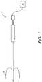
- FIG. 1is a schematic diagram of a tissue ablation system in accordance with some embodiments of the invention.
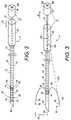
- FIG. 2is a perspective view of the ablation probe used in the system of FIG. 1 , wherein an electrode array is particularly shown retracted;
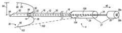
- FIG. 3is a perspective view of the ablation probe of FIG. 2 , wherein an electrode array is particularly shown deployed;
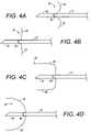
- FIG. 4A–4Dare side views of ablation probes in accordance with other embodiments of the invention, showing the ablation probes having electrode arrays with different configurations;
- FIG. 5is a perspective view of an ablation probe used in the system of FIG. 1 in accordance with other embodiments, wherein an electrode array is particularly shown retracted;
- FIG. 6is a perspective view of the ablation probe of FIG. 5 , wherein the electrode array is particularly shown deployed;
- FIGS. 7A–7Dare cross-sectional views, showing a method for treating tissue, in accordance with some embodiments of the invention.
- FIG. 1illustrates a tissue ablation system 2 constructed in accordance with some embodiments of the invention.
- the tissue ablation system 2includes a probe assembly 4 configured for introduction into the body of a patient for ablative treatment of target tissue, and a radio frequency (RF) generator 6 configured for supplying RF energy to the probe assembly 4 in a controlled manner.
- RFradio frequency
- the probe assembly 4includes an elongate cannula 12 , a shaft 20 slidably disposed within the cannula 12 , and an array 30 of electrodes 26 carried by the shaft 20 .
- the cannula 12has a distal end 14 , a proximal end 16 , and a central lumen 18 extending through the cannula 12 between the distal end 14 and the proximal end 16 .
- the cannula 12may be rigid, semi-rigid, or flexible depending upon the designed means for introducing the cannula 12 to the target tissue.
- the cannula 12is composed of a suitable material, such as plastic, metal or the like, and has a suitable length, typically in the range from 5 cm to 30 cm, preferably from 10 cm to 20 cm. The length of the cannula 12 can also have other dimensions. If composed of an electrically conductive material, the cannula 12 is preferably covered with an insulative material.
- the cannula 12has an outside cross sectional dimension consistent with its intended use, typically being from 0.5 mm to 5 mm, usually from 1.3 mm to 4 mm.
- the cannula 12may have an inner cross sectional dimension in the range from 0.3 mm to 4 mm, preferably from 1 mm to 3.5 mm.
- the cannula 12can also have other outside and inner cross sectional dimensions in other embodiments.
- longitudinal translation of the shaft 20 relative to the cannula 12 in a proximal direction 40deploys the electrode tines 26 from the distal end 14 of the cannula 12 ( FIG. 3 ), and longitudinal translation of the shaft 20 relative to the cannula 12 in a distal direction 42 retracts the electrode tines 26 into the distal end 14 of the cannula 12 ( FIG. 2 ).
- the shaft 20comprises a distal end 22 and a proximal end 24 .
- the shaft 20is composed of a suitable material, such as plastic, metal or the like.
- each electrode 26takes the form of an electrode tine, which resembles the shape of a needle or wire.
- Each of the electrodes 26is in the form of a small diameter metal element, which can penetrate into tissue as it is advanced from a target site within the target region.
- distal ends 66 of the electrodes 26may be honed or sharpened to facilitate their ability to penetrate tissue.
- the distal ends 66 of these electrodes 26may be hardened using conventional heat treatment or other metallurgical processes. They may be partially covered with insulation, although they will be at least partially free from insulation over their distal portions.
- the array 30 of electrodes 26When deployed from the cannula 12 , the array 30 of electrodes 26 has a deployed configuration that defines a volume having a periphery with a radius 84 in the range from 0.5 to 4 cm. However, in other embodiments, the maximum radius can be other values.
- the electrodes 26are resilient and pre-shaped to assume a desired configuration when advanced into tissue. In the illustrated embodiments, the electrodes 26 diverge radially outwardly from the cannula 12 in a uniform pattern, i.e., with the spacing between adjacent electrodes 26 diverging in a substantially uniform and/or symmetric pattern.
- each electrode 26has a flared curvilinear profile that resembles a portion of a parabola. Particularly, when the electrodes 26 are deployed, the electrodes 26 each extends proximally, and then everts distally, such that each electrode 26 forms a profile that resembles at least a portion of a parabola. As shown in FIG. 3 , the deployed electrode 26 is located at the distal end 14 of the cannula, and each deployed electrode 26 has a distal end that points at least partially towards a distal direction.
- Such configurationis advantageous in that it allows the deployed electrodes 26 to be used to compress tissue that is circumscribed by the deployed electrodes 26 , thereby reducing blood flow to the tissue and reducing an amount of heat that could be carried away by blood flow. Also, use of the electrodes 26 having the configuration shown in FIG. 3 can prevent or substantially reduce the risk of injury to vessel or sensitive tissue that is adjacent to a distal region of a target area.
- the distal end 66 of the electrode 26is considered pointing at least partially towards a distal direction when an instantaneous tangent 100 at a point 102 along the distal end 66 of the electrode 26 forms an angle 104 that is less than 90° with an axis 106 of the cannula 12 .
- the electrodes 26should not be limited to having the profiles shown in FIG. 3 , and that in alternative embodiments, the electrodes 26 can have different deployed profiles.
- the electrodes 26can each have a flared deployed profile ( FIG. 4A ), a substantially rectilinear deployed profile ( FIG. 4B ), a deployed profile that resembles a 90° bent ( FIG. 4C ), or a deployed profile that resembles a portion (e.g., a quarter) of a circle or an ellipse ( FIG. 4D ).
- the probe assembly 4can have more or fewer than two electrodes 26 .
- pairs of adjacent electrodes 26can be spaced from each other in similar or identical, repeated patterns and can be symmetrically positioned about an axis of the shaft 20 . It will be appreciated that a wide variety of particular patterns can be provided to uniformly cover the region to be treated. In other embodiments, the electrodes 26 may be spaced from each other in a non-uniform pattern.
- the electrodes 26can be made from a variety of electrically conductive elastic materials. Very desirable materials of construction, from a mechanical point of view, are materials which maintain their shape despite being subjected to high stress. Certain “super-elastic alloys” include nickel/titanium alloys, copper/zinc alloys, or nickel/aluminum alloys. Alloys that may be used are also described in U.S. Pat. Nos. 3,174,851, 3,351,463, and 3,753,700, the disclosures of which are hereby expressly incorporated by reference. The electrodes 26 may also be made from any of a wide variety of stainless steels.
- the electrodes 26may also include the Platinum Group metals, especially platinum, rhodium, palladium, rhenium, as well as tungsten, gold, silver, tantalum, and alloys of these metals. These metals are largely biologically inert. They also have significant radiopacity to allow the electrodes 26 to be visualized in-situ, and their alloys may be tailored to accomplish an appropriate blend of flexibility and stiffness. They may be coated onto the electrodes 26 or be mixed with another material used for construction of the electrodes 26 .
- Platinum Group metalsespecially platinum, rhodium, palladium, rhenium, as well as tungsten, gold, silver, tantalum, and alloys of these metals. These metals are largely biologically inert. They also have significant radiopacity to allow the electrodes 26 to be visualized in-situ, and their alloys may be tailored to accomplish an appropriate blend of flexibility and stiffness. They may be coated onto the electrodes 26 or be mixed with another material used for construction of the electrodes
- the electrodes 26have generally uniform widths and rectangular cross-sections.
- the rectangular cross-sectionsmake the electrodes 26 stiffer in one direction (e.g., the transverse direction) and more flexible in another direction (e.g., the radial direction). By increasing transverse stiffness, proper circumferential alignment of the electrodes 26 within the lumen 18 of the cannula 12 is enhanced.
- the widths of the electrodes 26may be non-uniform, and the cross-sections of the electrodes 26 may be non-rectangular.
- Exemplary electrodeswill have a width (in the circumferential direction) in the range from 0.2 mm to 0.6 mm, preferably from 0.35 mm to 0.40 mm, and a thickness (in the radial direction) in the range from 0.05 mm to 0.3 mm, preferably from 0.1 mm to 0.2 mm.
- the probe assembly 4further includes an electrode 92 secured to the cannula 12 .
- the electrode 92is operative in conjunction with the array 30 to deliver energy to tissue.
- the electrodes 26 in the array 30are positive (or active) electrodes while the operative electrode 92 is a negative (or return) electrode for completing energy path(s). In such cases, energy is directed from the electrodes 26 in the array 30 radially inward towards the electrode 92 .
- the electrode 92can be active electrode while the electrodes 26 in the array 30 are return electrodes for completing energy path(s), in which cases, energy is directed from the electrode 92 radially outward towards the electrodes 26 .
- the operative electrode 92has a tubular shape, but can have other shapes in alternative embodiments.
- the operative electrode 92also has a sharp distal tip 94 for piercing tissue.
- the operative electrode 92is secured to the distal end 14 of the cannula 12 such that the distal tip of the operative electrode 92 is distal to the distal end 14 .
- the operative electrode 92can be secured to the cannula 12 at a point along a length of the cannula 12 . In such case, the distal tip of the cannula 12 can have a sharp profile for piercing tissue.
- the array 30 of electrodes 26 and the operative electrode 92are used to deliver RF current in a bipolar fashion, which means that current will pass between the array 30 of electrodes 26 and the operative electrode 92 .
- the array 30 and the electrode 92will be insulated from each other in any region(s) where they would or could be in contact with each other during a power delivery phase.
- an insulator 90can be provided to electrically insulate the operative electrode 92 from the electrodes 26 in the array 30 .
- the electrode array 30can be electrically insulated from the operative electrode 92 by an insulator having other shapes or configurations that is placed at different locations in the probe assembly 4 .
- the probe assembly 4can include insulators within the respective openings 80 .
- the insulator 90is not needed, and the ablation probe 4 does not include the insulator 90 .
- the RF currentis delivered to the electrode array 30 in a monopolar fashion, which means that current will pass from the electrode array 30 , which is configured to concentrate the energy flux in order to have an injurious effect on the surrounding tissue, to a dispersive electrode (not shown), which is located remotely from the electrode array 30 and has a sufficiently large area (typically 130 cm 2 for an adult), so that the current density is low and non-injurious to surrounding tissue.
- the electrode assembly 4does not include the operative electrode 92 .
- the dispersive electrodemay be attached externally to the patient, e.g., using a contact pad placed on the patient's flank.
- the electrode assembly 4can include the operative electrode 92 for delivering ablation energy in a monopolar configuration.
- the array 30 of electrodes 26 and the operative electrode 92are monopolar electrodes, and current will pass from the electrodes 26 and the electrode 92 to the dispersive electrode to thereby deliver ablation energy in a monopolar configuration.
- the probe assembly 4further includes a handle assembly 27 , which includes a handle portion 28 mounted to the proximal end 24 of the shaft 20 , and a handle body 29 mounted to the proximal end 16 of the cannula 12 .
- the handle portion 28is slidably engaged with the handle body 29 (and the cannula 20 ).
- the handle portion 28also includes two electrical connectors 38 a , 38 b , which allows the probe assembly 4 to be connected to the generator 6 during use.
- the electrical connector 38 ais electrically coupled to the electrodes 26
- the electrical connector 38 bis electrically coupled to the electrode 92 .
- the electrical connector 38 acan be conveniently coupled to the electrodes 26 via the shaft 20 (which will be electrically conductive), although in other embodiments, the connector 38 a can be coupled to the electrodes 26 via separate wires (not shown).
- the handle portion 28 and the handle body 29can be composed of any suitable rigid material, such as, e.g., metal, plastic, or the like. In other embodiments, if the electrode assembly 4 does not include the electrode 92 , then the electrode assembly 4 does not include the connector 38 b.
- a markermay be placed on the handle portion 28 and/or on the proximal end 24 of the shaft 20 for indicating a rotational orientation or a position of the handle portion 28 relative to the shaft 20 (and the electrodes 26 ) during use.
- the handle assembly 27can have an indexing feature.
- the proximal end 24 of the shaft 20 or the handle portion 28can have one or more keys that mate with respective slot(s) at the interior surface of the cannula 12 or the handle body 29 .
- Such indexing featureallows circumferential alignment of the shaft 20 (and the array 30 ) relative to the cannula 12 .
- Angle indexing devicesthat may be used include those described in U.S.
- the handle portion 28may also include a locking mechanism (not shown) to temporarily lock against the shaft 20 to provide a more stable indexing.
- the locking mechanismmay include an axially-sliding clutch assembly that is slidable along an axis of the shaft 20 to thereby secure the handle portion 28 against the shaft 20 .
- Other securing devices known in the artmay also be used.
- the RF generator 6is electrically connected to the electrical connectors 38 a 38 b , which may be directly or indirectly (e.g., via a conductor) electrically coupled to the electrode array 30 .
- the RF generator 6is a conventional RF power supply that operates at a frequency in the range from 200 KHz to 1.25 MHz, with a conventional sinusoidal or non-sinusoidal wave form.
- Such power suppliesare available from many commercial suppliers, such as Valleylab, Aspen, and Bovie.
- Most general purpose electrosurgical power suppliesoperate at higher voltages and powers than would normally be necessary or suitable for vessel occlusion. Thus, such power supplies would usually be operated at the lower ends of their voltage and power capabilities.
- More suitable power supplieswill be capable of supplying an ablation current at a relatively low voltage, typically below 150V (peak-to-peak), usually being from 50V to 100V.
- the powerwill usually be from 20 W to 200 W, usually having a sine wave form, although other wave forms would also be acceptable.
- Power supplies capable of operating within these rangesare available from commercial vendors, such as Boston Scientific Corporation of San Jose, Calif., which markets these power supplies under the trademarks RF2000 (100 W) and RF3000 (200 W).
- FIG. 5illustrates a variation of the probe assembly 4 , wherein the distal ends 66 of the electrodes 26 point at least partially towards a distal direction (e.g., with the distal ends 66 being distal to the proximal ends 67 of the electrodes 26 ) when confined within the lumen 18 of the cannula.
- the electrodes 26can be deployed out of the lumen 18 of the cannula by advancing the shaft 20 distally relative to the cannula 12 ( FIG. 6 ).
- each electrode 26has a flared curvilinear profile that resembles a portion of a parabola and has a distal end that points at least partially towards a distal direction when deployed.
- the electrodes 26can have different deployed shapes/profiles, as similarly discussed previously.
- the handle assembly 27can be configured such that the electrodes 26 can be deployed by rotating the handle portion 28 relative to the handle body 27 .
- the shaft 20can have a screw-like configuration, which allows the shaft 20 to be distally advanced or proximally retracted by rotation of the shaft 20 .
- the array 30 of electrodes 26is rotatably coupled to the distal end 22 of the shaft 20 such that rotation of the shaft 20 does not rotate the electrodes 26 , but move them in an approximate longitudinal direction.
- the cannula 12is first introduced within the treatment region TR, so that the distal end 14 of the cannula 12 is located at the target site TS, as shown in FIG. 7A .
- Thiscan be accomplished using any one of a variety of techniques.
- the cannula 12 and shaft 20may be introduced to the target site TS percutaneously directly through the patient's skin or through an open surgical incision.
- the cannula 12(or the electrode 92 ) may have a sharpened tip, e.g., in the form of a needle, to facilitate introduction to the target site TS.
- a sharpened tipe.g., in the form of a needle
- the cannula 12may be introduced using an internal stylet that is subsequently exchanged for the shaft 20 and electrode array 30 . In this latter case, the cannula 12 can be relatively flexible, since the initial column strength will be provided by the stylet. More alternatively, a component or element may be provided for introducing the cannula 12 to the target site TS.
- a conventional sheath and sharpened obturator (stylet) assemblycan be used to initially access the tissue T.
- the assemblycan be positioned under ultrasonic or other conventional imaging, with the obturator/stylet then removed to leave an access lumen through the sheath.
- the cannula 12 and shaft 20can then be introduced through the sheath lumen, so that the distal end 14 of the cannula 12 advances from the sheath to the target site TS.
- the electrode array 30is deployed out of the lumen 18 of the cannula 12 , as shown in FIG. 7B .
- the electrode array 30is fully deployed to span at least a portion of the treatment region TR, as shown in FIG. 7B .
- the needle electrodes 26may be only partially deployed or deployed incrementally in stages during a procedure.
- the RF generator 6is then connected to the probe assembly 4 via the electrical connectors 38 a 38 b , and the RF generator 6 is operated to deliver ablation energy to the needle electrodes 26 either in a monopolar mode or a bipolar mode.
- ablation energyis being delivered, pressure can be applied to the handle assembly 27 (in the direction 400 shown), thereby causing the electrodes 26 to compress tissue that is being circumscribed by the deployed electrodes 26 ( FIG. 7C ).
- the compression on the tissuereduces blood flow to the tissue, thereby preventing or reducing heat from being carried away by blood flow, which in turn, improves a tissue ablation rate.
- the treatment region TRis necrosed, thereby creating a lesion on the treatment region TR ( FIG. 7D ).
- a single ablationmay be sufficient to create a desired lesion.
- the needle electrodes 26may be introduced and deployed at different target site(s), and the same steps discussed previously may be repeated.
- the needle electrodes 26are retracted into the lumen 18 of the cannula 12 , and the probe assembly 4 is removed from the treatment region TR.
- the array 30 of electrodes 26can be manufactured as a single component.
- the “array of electrodes”should not be limited to a plurality of separate electrodes, and includes a single structure (e.g., an electrode) having different conductive portions.
- the present inventionis intended to cover alternatives, modifications, and equivalents that may fall within the spirit and scope of the present invention as defined by the claims.
Landscapes
- Health & Medical Sciences (AREA)
- Surgery (AREA)
- Engineering & Computer Science (AREA)
- Life Sciences & Earth Sciences (AREA)
- Heart & Thoracic Surgery (AREA)
- Biomedical Technology (AREA)
- Nuclear Medicine, Radiotherapy & Molecular Imaging (AREA)
- Otolaryngology (AREA)
- Neurology (AREA)
- Neurosurgery (AREA)
- Physics & Mathematics (AREA)
- Plasma & Fusion (AREA)
- Medical Informatics (AREA)
- Molecular Biology (AREA)
- Animal Behavior & Ethology (AREA)
- General Health & Medical Sciences (AREA)
- Public Health (AREA)
- Veterinary Medicine (AREA)
- Surgical Instruments (AREA)
Abstract
Description
Claims (38)
Priority Applications (8)
| Application Number | Priority Date | Filing Date | Title |
|---|---|---|---|
| US10/966,677US7229438B2 (en) | 2004-10-14 | 2004-10-14 | Ablation probe with distal inverted electrode array |
| PCT/US2005/034023WO2006044105A1 (en) | 2004-10-14 | 2005-09-21 | Ablation probe with distal inverted electrode array |
| AU2005296144AAU2005296144A1 (en) | 2004-10-14 | 2005-09-21 | Ablation probe with distal inverted electrode array |
| EP05820951AEP1799137A1 (en) | 2004-10-14 | 2005-09-21 | Ablation probe with distal inverted electrode array |
| JP2007536704AJP2008516667A (en) | 2004-10-14 | 2005-09-21 | Ablation probe with electrode array deflecting distally |
| CA002581914ACA2581914A1 (en) | 2004-10-14 | 2005-09-21 | Ablation probe with distal inverted electrode array |
| US11/742,526US8052679B2 (en) | 2004-10-14 | 2007-04-30 | Ablation probe with electrode array and tissue penetrating distal tip electrode |
| US13/291,857US9144457B2 (en) | 2004-10-14 | 2011-11-08 | Ablation probe with distal inverted electrode array |
Applications Claiming Priority (1)
| Application Number | Priority Date | Filing Date | Title |
|---|---|---|---|
| US10/966,677US7229438B2 (en) | 2004-10-14 | 2004-10-14 | Ablation probe with distal inverted electrode array |
Related Child Applications (1)
| Application Number | Title | Priority Date | Filing Date |
|---|---|---|---|
| US11/742,526ContinuationUS8052679B2 (en) | 2004-10-14 | 2007-04-30 | Ablation probe with electrode array and tissue penetrating distal tip electrode |
Publications (2)
| Publication Number | Publication Date |
|---|---|
| US20060084965A1 US20060084965A1 (en) | 2006-04-20 |
| US7229438B2true US7229438B2 (en) | 2007-06-12 |
Family
ID=35735223
Family Applications (3)
| Application Number | Title | Priority Date | Filing Date |
|---|---|---|---|
| US10/966,677Expired - LifetimeUS7229438B2 (en) | 2004-10-14 | 2004-10-14 | Ablation probe with distal inverted electrode array |
| US11/742,526Expired - Fee RelatedUS8052679B2 (en) | 2004-10-14 | 2007-04-30 | Ablation probe with electrode array and tissue penetrating distal tip electrode |
| US13/291,857Expired - Fee RelatedUS9144457B2 (en) | 2004-10-14 | 2011-11-08 | Ablation probe with distal inverted electrode array |
Family Applications After (2)
| Application Number | Title | Priority Date | Filing Date |
|---|---|---|---|
| US11/742,526Expired - Fee RelatedUS8052679B2 (en) | 2004-10-14 | 2007-04-30 | Ablation probe with electrode array and tissue penetrating distal tip electrode |
| US13/291,857Expired - Fee RelatedUS9144457B2 (en) | 2004-10-14 | 2011-11-08 | Ablation probe with distal inverted electrode array |
Country Status (6)
| Country | Link |
|---|---|
| US (3) | US7229438B2 (en) |
| EP (1) | EP1799137A1 (en) |
| JP (1) | JP2008516667A (en) |
| AU (1) | AU2005296144A1 (en) |
| CA (1) | CA2581914A1 (en) |
| WO (1) | WO2006044105A1 (en) |
Cited By (49)
| Publication number | Priority date | Publication date | Assignee | Title |
|---|---|---|---|---|
| US7468042B2 (en) | 2002-04-16 | 2008-12-23 | Vivant Medical, Inc. | Localization element with energized tip |
| US20090326561A1 (en)* | 2008-06-27 | 2009-12-31 | Ethicon Endo-Surgery, Inc. | Surgical suture arrangement |
| US20090326620A1 (en)* | 2008-06-26 | 2009-12-31 | Francesca Rossetto | Deployable Microwave Antenna for Treating Tissue |
| US20100257850A1 (en)* | 2007-11-21 | 2010-10-14 | Hino Motors Ltd. | Exhaust emission control device |
| US7875024B2 (en) | 2003-07-18 | 2011-01-25 | Vivant Medical, Inc. | Devices and methods for cooling microwave antennas |
| US20110098704A1 (en)* | 2009-10-28 | 2011-04-28 | Ethicon Endo-Surgery, Inc. | Electrical ablation devices |
| US8068921B2 (en) | 2006-09-29 | 2011-11-29 | Vivant Medical, Inc. | Microwave antenna assembly and method of using the same |
| US8292880B2 (en) | 2007-11-27 | 2012-10-23 | Vivant Medical, Inc. | Targeted cooling of deployable microwave antenna |
| US8353487B2 (en) | 2009-12-17 | 2013-01-15 | Ethicon Endo-Surgery, Inc. | User interface support devices for endoscopic surgical instruments |
| US8403926B2 (en) | 2008-06-05 | 2013-03-26 | Ethicon Endo-Surgery, Inc. | Manually articulating devices |
| US8409200B2 (en) | 2008-09-03 | 2013-04-02 | Ethicon Endo-Surgery, Inc. | Surgical grasping device |
| US8425505B2 (en) | 2007-02-15 | 2013-04-23 | Ethicon Endo-Surgery, Inc. | Electroporation ablation apparatus, system, and method |
| US8480657B2 (en) | 2007-10-31 | 2013-07-09 | Ethicon Endo-Surgery, Inc. | Detachable distal overtube section and methods for forming a sealable opening in the wall of an organ |
| US8496574B2 (en) | 2009-12-17 | 2013-07-30 | Ethicon Endo-Surgery, Inc. | Selectively positionable camera for surgical guide tube assembly |
| US8506564B2 (en) | 2009-12-18 | 2013-08-13 | Ethicon Endo-Surgery, Inc. | Surgical instrument comprising an electrode |
| US8579897B2 (en) | 2007-11-21 | 2013-11-12 | Ethicon Endo-Surgery, Inc. | Bipolar forceps |
| US8608652B2 (en) | 2009-11-05 | 2013-12-17 | Ethicon Endo-Surgery, Inc. | Vaginal entry surgical devices, kit, system, and method |
| US8679003B2 (en) | 2008-05-30 | 2014-03-25 | Ethicon Endo-Surgery, Inc. | Surgical device and endoscope including same |
| US8690868B2 (en) | 1999-06-17 | 2014-04-08 | Covidien Lp | Needle kit and method for microwave ablation, track coagulation, and biopsy |
| US8771260B2 (en) | 2008-05-30 | 2014-07-08 | Ethicon Endo-Surgery, Inc. | Actuating and articulating surgical device |
| US8808282B2 (en) | 2002-04-16 | 2014-08-19 | Covidien Lp | Microwave antenna having a curved configuration |
| US8906035B2 (en) | 2008-06-04 | 2014-12-09 | Ethicon Endo-Surgery, Inc. | Endoscopic drop off bag |
| US8939897B2 (en) | 2007-10-31 | 2015-01-27 | Ethicon Endo-Surgery, Inc. | Methods for closing a gastrotomy |
| US9005198B2 (en) | 2010-01-29 | 2015-04-14 | Ethicon Endo-Surgery, Inc. | Surgical instrument comprising an electrode |
| US9011431B2 (en) | 2009-01-12 | 2015-04-21 | Ethicon Endo-Surgery, Inc. | Electrical ablation devices |
| US9028483B2 (en) | 2009-12-18 | 2015-05-12 | Ethicon Endo-Surgery, Inc. | Surgical instrument comprising an electrode |
| US9049987B2 (en) | 2011-03-17 | 2015-06-09 | Ethicon Endo-Surgery, Inc. | Hand held surgical device for manipulating an internal magnet assembly within a patient |
| US9078662B2 (en) | 2012-07-03 | 2015-07-14 | Ethicon Endo-Surgery, Inc. | Endoscopic cap electrode and method for using the same |
| US9131836B2 (en) | 2011-08-25 | 2015-09-15 | Covidien Lp | Transmitting torque to an operative element through a working channel |
| US20150313669A1 (en)* | 2014-05-04 | 2015-11-05 | Diros Technology Inc. | Radiofrequency Probes with Retractable Multi-Tined Electrodes |
| US9220526B2 (en) | 2008-11-25 | 2015-12-29 | Ethicon Endo-Surgery, Inc. | Rotational coupling device for surgical instrument with flexible actuators |
| US9233241B2 (en) | 2011-02-28 | 2016-01-12 | Ethicon Endo-Surgery, Inc. | Electrical ablation devices and methods |
| US9254169B2 (en) | 2011-02-28 | 2016-02-09 | Ethicon Endo-Surgery, Inc. | Electrical ablation devices and methods |
| US9277957B2 (en) | 2012-08-15 | 2016-03-08 | Ethicon Endo-Surgery, Inc. | Electrosurgical devices and methods |
| US9314620B2 (en) | 2011-02-28 | 2016-04-19 | Ethicon Endo-Surgery, Inc. | Electrical ablation devices and methods |
| US9427255B2 (en) | 2012-05-14 | 2016-08-30 | Ethicon Endo-Surgery, Inc. | Apparatus for introducing a steerable camera assembly into a patient |
| US9545290B2 (en) | 2012-07-30 | 2017-01-17 | Ethicon Endo-Surgery, Inc. | Needle probe guide |
| US9572623B2 (en) | 2012-08-02 | 2017-02-21 | Ethicon Endo-Surgery, Inc. | Reusable electrode and disposable sheath |
| US10092291B2 (en) | 2011-01-25 | 2018-10-09 | Ethicon Endo-Surgery, Inc. | Surgical instrument with selectively rigidizable features |
| US10098527B2 (en) | 2013-02-27 | 2018-10-16 | Ethidcon Endo-Surgery, Inc. | System for performing a minimally invasive surgical procedure |
| US10105141B2 (en) | 2008-07-14 | 2018-10-23 | Ethicon Endo-Surgery, Inc. | Tissue apposition clip application methods |
| US10136942B1 (en)* | 2014-10-21 | 2018-11-27 | Cosman Instruments, Llc | Electrosurgical system |
| US10314649B2 (en) | 2012-08-02 | 2019-06-11 | Ethicon Endo-Surgery, Inc. | Flexible expandable electrode and method of intraluminal delivery of pulsed power |
| US10631915B1 (en)* | 2014-10-21 | 2020-04-28 | Cosman Instruments, Llc | Electrosurgical system |
| US20200129230A1 (en)* | 2018-10-24 | 2020-04-30 | Boston Scientific Scimed, Inc. | Movable electrodes for controlled irreversible electroporation ablative volumes |
| US10716618B2 (en) | 2010-05-21 | 2020-07-21 | Stratus Medical, LLC | Systems and methods for tissue ablation |
| US10736688B2 (en) | 2009-11-05 | 2020-08-11 | Stratus Medical, LLC | Methods and systems for spinal radio frequency neurotomy |
| US10779883B2 (en)* | 2015-09-09 | 2020-09-22 | Baylis Medical Company Inc. | Epicardial access system and methods |
| US11523858B2 (en) | 2017-08-11 | 2022-12-13 | Bradley D. Vilims | System and method for RF ablation with generated images of ablated tissue lesions |
Families Citing this family (76)
| Publication number | Priority date | Publication date | Assignee | Title |
|---|---|---|---|---|
| EP1812104B1 (en)* | 2004-10-20 | 2012-11-21 | Boston Scientific Limited | Leadless cardiac stimulation systems |
| US8211104B2 (en)* | 2005-01-06 | 2012-07-03 | Boston Scientific Scimed, Inc. | Co-access bipolar ablation probe |
| US7896874B2 (en)* | 2005-12-29 | 2011-03-01 | Boston Scientific Scimed, Inc. | RF ablation probes with tine valves |
| US8206300B2 (en) | 2008-08-26 | 2012-06-26 | Gynesonics, Inc. | Ablation device with articulated imaging transducer |
| US20100056926A1 (en)* | 2008-08-26 | 2010-03-04 | Gynesonics, Inc. | Ablation device with articulated imaging transducer |
| US10595819B2 (en) | 2006-04-20 | 2020-03-24 | Gynesonics, Inc. | Ablation device with articulated imaging transducer |
| EP1897506B1 (en)* | 2006-09-08 | 2010-03-03 | Ethicon Endo-Surgery, Inc. | A surgical instrument for performing controlled myotomies |
| EP2097029A1 (en) | 2006-12-27 | 2009-09-09 | Boston Scientific Limited | Rf ablation probe array advancing device |
| US20080171984A1 (en)* | 2007-01-11 | 2008-07-17 | Miller Peter C | Cannula driver and system |
| US9867652B2 (en) | 2008-04-29 | 2018-01-16 | Virginia Tech Intellectual Properties, Inc. | Irreversible electroporation using tissue vasculature to treat aberrant cell masses or create tissue scaffolds |
| US8992517B2 (en) | 2008-04-29 | 2015-03-31 | Virginia Tech Intellectual Properties Inc. | Irreversible electroporation to treat aberrant cell masses |
| US10702326B2 (en) | 2011-07-15 | 2020-07-07 | Virginia Tech Intellectual Properties, Inc. | Device and method for electroporation based treatment of stenosis of a tubular body part |
| US10238447B2 (en) | 2008-04-29 | 2019-03-26 | Virginia Tech Intellectual Properties, Inc. | System and method for ablating a tissue site by electroporation with real-time monitoring of treatment progress |
| US9598691B2 (en) | 2008-04-29 | 2017-03-21 | Virginia Tech Intellectual Properties, Inc. | Irreversible electroporation to create tissue scaffolds |
| US11272979B2 (en) | 2008-04-29 | 2022-03-15 | Virginia Tech Intellectual Properties, Inc. | System and method for estimating tissue heating of a target ablation zone for electrical-energy based therapies |
| US10272178B2 (en) | 2008-04-29 | 2019-04-30 | Virginia Tech Intellectual Properties Inc. | Methods for blood-brain barrier disruption using electrical energy |
| US10245098B2 (en) | 2008-04-29 | 2019-04-02 | Virginia Tech Intellectual Properties, Inc. | Acute blood-brain barrier disruption using electrical energy based therapy |
| US10117707B2 (en) | 2008-04-29 | 2018-11-06 | Virginia Tech Intellectual Properties, Inc. | System and method for estimating tissue heating of a target ablation zone for electrical-energy based therapies |
| US9198733B2 (en) | 2008-04-29 | 2015-12-01 | Virginia Tech Intellectual Properties, Inc. | Treatment planning for electroporation-based therapies |
| US11254926B2 (en) | 2008-04-29 | 2022-02-22 | Virginia Tech Intellectual Properties, Inc. | Devices and methods for high frequency electroporation |
| US9283051B2 (en) | 2008-04-29 | 2016-03-15 | Virginia Tech Intellectual Properties, Inc. | System and method for estimating a treatment volume for administering electrical-energy based therapies |
| CA2732309C (en) | 2008-07-30 | 2018-04-10 | Ecole Polytechnique Federale De Lausanne (Epfl) | Apparatus and method for optimized stimulation of a neurological target |
| JP5667987B2 (en) | 2008-11-12 | 2015-02-12 | エコーレ ポリテクニーク フェデラーレ デ ローザンヌ (イーピーエフエル) | Micromachined nerve stimulation device |
| US8753335B2 (en)* | 2009-01-23 | 2014-06-17 | Angiodynamics, Inc. | Therapeutic energy delivery device with rotational mechanism |
| US8632534B2 (en) | 2009-04-03 | 2014-01-21 | Angiodynamics, Inc. | Irreversible electroporation (IRE) for congestive obstructive pulmonary disease (COPD) |
| US11638603B2 (en) | 2009-04-09 | 2023-05-02 | Virginia Tech Intellectual Properties, Inc. | Selective modulation of intracellular effects of cells using pulsed electric fields |
| US11382681B2 (en) | 2009-04-09 | 2022-07-12 | Virginia Tech Intellectual Properties, Inc. | Device and methods for delivery of high frequency electrical pulses for non-thermal ablation |
| WO2010138919A2 (en) | 2009-05-28 | 2010-12-02 | Angiodynamics, Inc. | System and method for synchronizing energy delivery to the cardiac rhythm |
| US9895189B2 (en) | 2009-06-19 | 2018-02-20 | Angiodynamics, Inc. | Methods of sterilization and treating infection using irreversible electroporation |
| WO2011041322A1 (en)* | 2009-09-30 | 2011-04-07 | Boston Scientific Scimed, Inc. | Medical probe with translatable co-access cannula |
| AU2015261694C1 (en)* | 2009-11-05 | 2021-11-25 | Stratus Medical, LLC | Methods and systems for spinal radio frequency neurotomy |
| CA2795159C (en) | 2010-04-01 | 2020-11-03 | Ecole Polytechnique Federale De Lausanne | Device for interacting with neurological tissue and methods of making and using the same |
| CN105167841A (en)* | 2010-05-21 | 2015-12-23 | 光轮概念公司 | Systems and methods for tissue ablation |
| US9358365B2 (en)* | 2010-07-30 | 2016-06-07 | Boston Scientific Scimed, Inc. | Precision electrode movement control for renal nerve ablation |
| EP2627274B1 (en) | 2010-10-13 | 2022-12-14 | AngioDynamics, Inc. | System for electrically ablating tissue of a patient |
| WO2012088149A2 (en) | 2010-12-20 | 2012-06-28 | Virginia Tech Intellectual Properties, Inc. | High-frequency electroporation for cancer therapy |
| US10112045B2 (en) | 2010-12-29 | 2018-10-30 | Medtronic, Inc. | Implantable medical device fixation |
| US9775982B2 (en) | 2010-12-29 | 2017-10-03 | Medtronic, Inc. | Implantable medical device fixation |
| US9078665B2 (en) | 2011-09-28 | 2015-07-14 | Angiodynamics, Inc. | Multiple treatment zone ablation probe |
| US9414881B2 (en) | 2012-02-08 | 2016-08-16 | Angiodynamics, Inc. | System and method for increasing a target zone for electrical ablation |
| US10485435B2 (en) | 2012-03-26 | 2019-11-26 | Medtronic, Inc. | Pass-through implantable medical device delivery catheter with removeable distal tip |
| US20150342668A1 (en)* | 2013-02-21 | 2015-12-03 | Stryker Corporation | Tissue ablation cannula and elecgtrode assembly that can be selectively operated with one or more active tips |
| US10071243B2 (en) | 2013-07-31 | 2018-09-11 | Medtronic, Inc. | Fixation for implantable medical devices |
| US10864041B2 (en)* | 2014-01-29 | 2020-12-15 | Baylis Medical Company Inc. | Side-port catheter |
| WO2015175570A1 (en) | 2014-05-12 | 2015-11-19 | Virginia Tech Intellectual Properties, Inc. | Selective modulation of intracellular effects of cells using pulsed electric fields |
| WO2015173787A1 (en)* | 2014-05-16 | 2015-11-19 | Aleva Neurotherapeutics Sa | Device for interacting with neurological tissue and methods of making and using the same |
| US11311718B2 (en) | 2014-05-16 | 2022-04-26 | Aleva Neurotherapeutics Sa | Device for interacting with neurological tissue and methods of making and using the same |
| US10478620B2 (en) | 2014-08-26 | 2019-11-19 | Medtronic, Inc. | Interventional medical systems, devices, and methods of use |
| US9474894B2 (en) | 2014-08-27 | 2016-10-25 | Aleva Neurotherapeutics | Deep brain stimulation lead |
| US12114911B2 (en) | 2014-08-28 | 2024-10-15 | Angiodynamics, Inc. | System and method for ablating a tissue site by electroporation with real-time pulse monitoring |
| US10694972B2 (en) | 2014-12-15 | 2020-06-30 | Virginia Tech Intellectual Properties, Inc. | Devices, systems, and methods for real-time monitoring of electrophysical effects during tissue treatment |
| US10531907B2 (en) | 2015-11-20 | 2020-01-14 | Covidien Lp | Devices, systems, and methods for treating ulcerative colitis and other inflammatory bowel diseases |
| US10675085B2 (en) | 2015-11-23 | 2020-06-09 | Boston Scientific Scimed, Inc. | Devices and methods for enhanced denervation procedures |
| US10099050B2 (en) | 2016-01-21 | 2018-10-16 | Medtronic, Inc. | Interventional medical devices, device systems, and fixation components thereof |
| CN115715689B (en) | 2016-11-11 | 2025-01-17 | 杰尼索尼克斯公司 | Tissue controlled treatment and dynamic interaction and comparison with tissue and/or treatment data |
| US10905492B2 (en) | 2016-11-17 | 2021-02-02 | Angiodynamics, Inc. | Techniques for irreversible electroporation using a single-pole tine-style internal device communicating with an external surface electrode |
| US11426578B2 (en) | 2017-09-15 | 2022-08-30 | Medtronic, Inc. | Electrodes for intra-cardiac pacemaker |
| US11607537B2 (en) | 2017-12-05 | 2023-03-21 | Virginia Tech Intellectual Properties, Inc. | Method for treating neurological disorders, including tumors, with electroporation |
| US10702692B2 (en) | 2018-03-02 | 2020-07-07 | Aleva Neurotherapeutics | Neurostimulation device |
| WO2019169259A1 (en) | 2018-03-02 | 2019-09-06 | Medtronic, Inc. | Implantable medical electrode assemblies and devices |
| US12390262B2 (en) | 2018-03-13 | 2025-08-19 | Virginia Tech Intellectual Properties, Inc. | Treatment planning system for immunotherapy enhancement via non-thermal ablation |
| US11311329B2 (en) | 2018-03-13 | 2022-04-26 | Virginia Tech Intellectual Properties, Inc. | Treatment planning for immunotherapy based treatments using non-thermal ablation techniques |
| US11925405B2 (en) | 2018-03-13 | 2024-03-12 | Virginia Tech Intellectual Properties, Inc. | Treatment planning system for immunotherapy enhancement via non-thermal ablation |
| WO2020106820A1 (en)* | 2018-11-21 | 2020-05-28 | Mayo Foundation For Medical Education And Research | Electrophysiological subcortical system |
| US11759632B2 (en) | 2019-03-28 | 2023-09-19 | Medtronic, Inc. | Fixation components for implantable medical devices |
| US11541232B2 (en) | 2019-06-18 | 2023-01-03 | Medtronic, Inc. | Electrode configuration for a medical device |
| US11950835B2 (en) | 2019-06-28 | 2024-04-09 | Virginia Tech Intellectual Properties, Inc. | Cycled pulsing to mitigate thermal damage for multi-electrode irreversible electroporation therapy |
| US11524139B2 (en) | 2019-07-15 | 2022-12-13 | Medtronic, Inc. | Catheter with active return curve |
| US11524143B2 (en) | 2019-07-15 | 2022-12-13 | Medtronic, Inc. | Catheter with distal and proximal fixation members |
| US12214189B2 (en) | 2019-07-24 | 2025-02-04 | Virginia Tech Intellectual Properties, Inc. | Fourier analysis spectroscopy for monitoring tissue impedance changes and treatment outcome during electroporation-based-therapies |
| US11684776B2 (en) | 2019-08-13 | 2023-06-27 | Medtronic, Inc. | Fixation component for multi-electrode implantable medical device |
| US11992675B2 (en) | 2020-02-04 | 2024-05-28 | Medtronic, Inc. | Implantable medical device including a tine housing |
| US11975206B2 (en) | 2020-03-06 | 2024-05-07 | Medtronic, Inc. | Multi-electrode implantable medical device (IMD) |
| US12179016B2 (en) | 2021-02-15 | 2024-12-31 | Medtronic, Inc. | Fixation component for multi-electrode implantable medical device |
| US12246181B2 (en) | 2021-04-02 | 2025-03-11 | Medtronic, Inc. | Dual chamber pacing |
| US12274842B2 (en) | 2021-06-08 | 2025-04-15 | Medtronic, Inc. | Guide wire system |
Citations (13)
| Publication number | Priority date | Publication date | Assignee | Title |
|---|---|---|---|---|
| US3174851A (en) | 1961-12-01 | 1965-03-23 | William J Buehler | Nickel-base alloys |
| US3351463A (en) | 1965-08-20 | 1967-11-07 | Alexander G Rozner | High strength nickel-base alloys |
| US3753700A (en) | 1970-07-02 | 1973-08-21 | Raychem Corp | Heat recoverable alloy |
| US5472441A (en)* | 1993-11-08 | 1995-12-05 | Zomed International | Device for treating cancer and non-malignant tumors and methods |
| US5507743A (en)* | 1993-11-08 | 1996-04-16 | Zomed International | Coiled RF electrode treatment apparatus |
| US5536267A (en)* | 1993-11-08 | 1996-07-16 | Zomed International | Multiple electrode ablation apparatus |
| WO1997006739A2 (en) | 1995-08-15 | 1997-02-27 | Rita Medical Systems, Inc. | Apparatus for ablation of a selected mass |
| US5827276A (en)* | 1995-03-24 | 1998-10-27 | Board Of Regents Of Univ Of Nebraksa | Apparatus for volumetric tissue ablation |
| US6090105A (en)* | 1995-08-15 | 2000-07-18 | Rita Medical Systems, Inc. | Multiple electrode ablation apparatus and method |
| US20040158239A1 (en)* | 2000-09-15 | 2004-08-12 | Behl Robert S. | Methods and systems for focused bipolar tissue ablation |
| US20050080409A1 (en)* | 2003-10-10 | 2005-04-14 | Scimed Life Systems, Inc. | Multi-zone bipolar ablation probe assembly |
| US20050107781A1 (en)* | 2003-11-18 | 2005-05-19 | Isaac Ostrovsky | System and method for tissue ablation |
| US20060217702A1 (en)* | 2005-03-25 | 2006-09-28 | Boston Scientific Scimed, Inc. | Ablation probe having a plurality of arrays of electrodes |
Family Cites Families (3)
| Publication number | Priority date | Publication date | Assignee | Title |
|---|---|---|---|---|
| US5672173A (en)* | 1995-08-15 | 1997-09-30 | Rita Medical Systems, Inc. | Multiple antenna ablation apparatus and method |
| US6312429B1 (en)* | 1998-09-01 | 2001-11-06 | Senorx, Inc. | Electrosurgical lesion location device |
| US6926713B2 (en) | 2002-12-11 | 2005-08-09 | Boston Scientific Scimed, Inc. | Angle indexer for medical devices |
- 2004
- 2004-10-14USUS10/966,677patent/US7229438B2/ennot_activeExpired - Lifetime
- 2005
- 2005-09-21EPEP05820951Apatent/EP1799137A1/ennot_activeWithdrawn
- 2005-09-21CACA002581914Apatent/CA2581914A1/ennot_activeAbandoned
- 2005-09-21WOPCT/US2005/034023patent/WO2006044105A1/enactiveApplication Filing
- 2005-09-21AUAU2005296144Apatent/AU2005296144A1/ennot_activeAbandoned
- 2005-09-21JPJP2007536704Apatent/JP2008516667A/enactivePending
- 2007
- 2007-04-30USUS11/742,526patent/US8052679B2/ennot_activeExpired - Fee Related
- 2011
- 2011-11-08USUS13/291,857patent/US9144457B2/ennot_activeExpired - Fee Related
Patent Citations (15)
| Publication number | Priority date | Publication date | Assignee | Title |
|---|---|---|---|---|
| US3174851A (en) | 1961-12-01 | 1965-03-23 | William J Buehler | Nickel-base alloys |
| US3351463A (en) | 1965-08-20 | 1967-11-07 | Alexander G Rozner | High strength nickel-base alloys |
| US3753700A (en) | 1970-07-02 | 1973-08-21 | Raychem Corp | Heat recoverable alloy |
| US5472441A (en)* | 1993-11-08 | 1995-12-05 | Zomed International | Device for treating cancer and non-malignant tumors and methods |
| US5507743A (en)* | 1993-11-08 | 1996-04-16 | Zomed International | Coiled RF electrode treatment apparatus |
| US5536267A (en)* | 1993-11-08 | 1996-07-16 | Zomed International | Multiple electrode ablation apparatus |
| US5855576A (en) | 1995-03-24 | 1999-01-05 | Board Of Regents Of University Of Nebraska | Method for volumetric tissue ablation |
| US5827276A (en)* | 1995-03-24 | 1998-10-27 | Board Of Regents Of Univ Of Nebraksa | Apparatus for volumetric tissue ablation |
| WO1997006739A2 (en) | 1995-08-15 | 1997-02-27 | Rita Medical Systems, Inc. | Apparatus for ablation of a selected mass |
| US6090105A (en)* | 1995-08-15 | 2000-07-18 | Rita Medical Systems, Inc. | Multiple electrode ablation apparatus and method |
| US20040158239A1 (en)* | 2000-09-15 | 2004-08-12 | Behl Robert S. | Methods and systems for focused bipolar tissue ablation |
| US20050080409A1 (en)* | 2003-10-10 | 2005-04-14 | Scimed Life Systems, Inc. | Multi-zone bipolar ablation probe assembly |
| WO2005037119A1 (en) | 2003-10-10 | 2005-04-28 | Boston Scientific Limited | Multi-zone bipolar ablation probe assembly |
| US20050107781A1 (en)* | 2003-11-18 | 2005-05-19 | Isaac Ostrovsky | System and method for tissue ablation |
| US20060217702A1 (en)* | 2005-03-25 | 2006-09-28 | Boston Scientific Scimed, Inc. | Ablation probe having a plurality of arrays of electrodes |
Non-Patent Citations (2)
| Title |
|---|
| PCT International Search Report for PCT/US2005/034023, Applicant: Boston Scientific Scimed, Inc., Form PCT/ISA/210 and 220, dated Feb. 22, 2006 (5 pages). |
| PCT Written Opinion of the International Search Authority for PCT/US2005/034023, Applicant: Boston Scientific Scimed, Inc., Form PCT/ISA/237, dated Feb. 22, 2006 (4 pages). |
Cited By (93)
| Publication number | Priority date | Publication date | Assignee | Title |
|---|---|---|---|---|
| US8690868B2 (en) | 1999-06-17 | 2014-04-08 | Covidien Lp | Needle kit and method for microwave ablation, track coagulation, and biopsy |
| US11045253B2 (en) | 2002-04-16 | 2021-06-29 | Covidien Lp | Electrosurgical energy channel splitters and systems for delivering electrosurgical energy |
| US7468042B2 (en) | 2002-04-16 | 2008-12-23 | Vivant Medical, Inc. | Localization element with energized tip |
| US10363097B2 (en) | 2002-04-16 | 2019-07-30 | Coviden Lp | Ablation system having multiple energy sources |
| US7846108B2 (en) | 2002-04-16 | 2010-12-07 | Vivant Medical, Inc. | Localization element with energized tip |
| US10143520B2 (en) | 2002-04-16 | 2018-12-04 | Covidien Lp | Microwave antenna guide assembly |
| US10039602B2 (en) | 2002-04-16 | 2018-08-07 | Covidien Lp | Electrosurgical energy channel splitters and systems for delivering electrosurgical energy |
| US8808282B2 (en) | 2002-04-16 | 2014-08-19 | Covidien Lp | Microwave antenna having a curved configuration |
| US10405921B2 (en) | 2003-07-18 | 2019-09-10 | Covidien Lp | Devices and methods for cooling microwave antennas |
| US9480528B2 (en) | 2003-07-18 | 2016-11-01 | Covidien Lp | Devices and methods for cooling microwave antennas |
| US7875024B2 (en) | 2003-07-18 | 2011-01-25 | Vivant Medical, Inc. | Devices and methods for cooling microwave antennas |
| US9820814B2 (en) | 2003-07-18 | 2017-11-21 | Covidien Lp | Devices and methods for cooling microwave antennas |
| US9468499B2 (en) | 2003-07-18 | 2016-10-18 | Covidien Lp | Devices and methods for cooling microwave antennas |
| US8068921B2 (en) | 2006-09-29 | 2011-11-29 | Vivant Medical, Inc. | Microwave antenna assembly and method of using the same |
| US9333032B2 (en) | 2006-09-29 | 2016-05-10 | Covidien Lp | Microwave antenna assembly and method of using the same |
| US10478248B2 (en) | 2007-02-15 | 2019-11-19 | Ethicon Llc | Electroporation ablation apparatus, system, and method |
| US8449538B2 (en) | 2007-02-15 | 2013-05-28 | Ethicon Endo-Surgery, Inc. | Electroporation ablation apparatus, system, and method |
| US8425505B2 (en) | 2007-02-15 | 2013-04-23 | Ethicon Endo-Surgery, Inc. | Electroporation ablation apparatus, system, and method |
| US9375268B2 (en) | 2007-02-15 | 2016-06-28 | Ethicon Endo-Surgery, Inc. | Electroporation ablation apparatus, system, and method |
| US8480657B2 (en) | 2007-10-31 | 2013-07-09 | Ethicon Endo-Surgery, Inc. | Detachable distal overtube section and methods for forming a sealable opening in the wall of an organ |
| US8939897B2 (en) | 2007-10-31 | 2015-01-27 | Ethicon Endo-Surgery, Inc. | Methods for closing a gastrotomy |
| US8579897B2 (en) | 2007-11-21 | 2013-11-12 | Ethicon Endo-Surgery, Inc. | Bipolar forceps |
| US20100257850A1 (en)* | 2007-11-21 | 2010-10-14 | Hino Motors Ltd. | Exhaust emission control device |
| US8292880B2 (en) | 2007-11-27 | 2012-10-23 | Vivant Medical, Inc. | Targeted cooling of deployable microwave antenna |
| US8679003B2 (en) | 2008-05-30 | 2014-03-25 | Ethicon Endo-Surgery, Inc. | Surgical device and endoscope including same |
| US8771260B2 (en) | 2008-05-30 | 2014-07-08 | Ethicon Endo-Surgery, Inc. | Actuating and articulating surgical device |
| US8906035B2 (en) | 2008-06-04 | 2014-12-09 | Ethicon Endo-Surgery, Inc. | Endoscopic drop off bag |
| US8403926B2 (en) | 2008-06-05 | 2013-03-26 | Ethicon Endo-Surgery, Inc. | Manually articulating devices |
| US20090326620A1 (en)* | 2008-06-26 | 2009-12-31 | Francesca Rossetto | Deployable Microwave Antenna for Treating Tissue |
| US8343149B2 (en) | 2008-06-26 | 2013-01-01 | Vivant Medical, Inc. | Deployable microwave antenna for treating tissue |
| US20090326561A1 (en)* | 2008-06-27 | 2009-12-31 | Ethicon Endo-Surgery, Inc. | Surgical suture arrangement |
| US8361112B2 (en) | 2008-06-27 | 2013-01-29 | Ethicon Endo-Surgery, Inc. | Surgical suture arrangement |
| US10105141B2 (en) | 2008-07-14 | 2018-10-23 | Ethicon Endo-Surgery, Inc. | Tissue apposition clip application methods |
| US11399834B2 (en) | 2008-07-14 | 2022-08-02 | Cilag Gmbh International | Tissue apposition clip application methods |
| US8409200B2 (en) | 2008-09-03 | 2013-04-02 | Ethicon Endo-Surgery, Inc. | Surgical grasping device |
| US10314603B2 (en) | 2008-11-25 | 2019-06-11 | Ethicon Llc | Rotational coupling device for surgical instrument with flexible actuators |
| US9220526B2 (en) | 2008-11-25 | 2015-12-29 | Ethicon Endo-Surgery, Inc. | Rotational coupling device for surgical instrument with flexible actuators |
| US9011431B2 (en) | 2009-01-12 | 2015-04-21 | Ethicon Endo-Surgery, Inc. | Electrical ablation devices |
| US10004558B2 (en) | 2009-01-12 | 2018-06-26 | Ethicon Endo-Surgery, Inc. | Electrical ablation devices |
| US20110098704A1 (en)* | 2009-10-28 | 2011-04-28 | Ethicon Endo-Surgery, Inc. | Electrical ablation devices |
| US10779882B2 (en) | 2009-10-28 | 2020-09-22 | Ethicon Endo-Surgery, Inc. | Electrical ablation devices |
| US11806070B2 (en) | 2009-11-05 | 2023-11-07 | Stratus Medical, LLC | Methods and systems for spinal radio frequency neurotomy |
| US8608652B2 (en) | 2009-11-05 | 2013-12-17 | Ethicon Endo-Surgery, Inc. | Vaginal entry surgical devices, kit, system, and method |
| US10925664B2 (en) | 2009-11-05 | 2021-02-23 | Stratus Medical, LLC | Methods for radio frequency neurotomy |
| US10736688B2 (en) | 2009-11-05 | 2020-08-11 | Stratus Medical, LLC | Methods and systems for spinal radio frequency neurotomy |
| US8353487B2 (en) | 2009-12-17 | 2013-01-15 | Ethicon Endo-Surgery, Inc. | User interface support devices for endoscopic surgical instruments |
| US8496574B2 (en) | 2009-12-17 | 2013-07-30 | Ethicon Endo-Surgery, Inc. | Selectively positionable camera for surgical guide tube assembly |
| US8506564B2 (en) | 2009-12-18 | 2013-08-13 | Ethicon Endo-Surgery, Inc. | Surgical instrument comprising an electrode |
| US9028483B2 (en) | 2009-12-18 | 2015-05-12 | Ethicon Endo-Surgery, Inc. | Surgical instrument comprising an electrode |
| US10098691B2 (en) | 2009-12-18 | 2018-10-16 | Ethicon Endo-Surgery, Inc. | Surgical instrument comprising an electrode |
| US9005198B2 (en) | 2010-01-29 | 2015-04-14 | Ethicon Endo-Surgery, Inc. | Surgical instrument comprising an electrode |
| US10966782B2 (en) | 2010-05-21 | 2021-04-06 | Stratus Medical, LLC | Needles and systems for radiofrequency neurotomy |
| US10716618B2 (en) | 2010-05-21 | 2020-07-21 | Stratus Medical, LLC | Systems and methods for tissue ablation |
| US10092291B2 (en) | 2011-01-25 | 2018-10-09 | Ethicon Endo-Surgery, Inc. | Surgical instrument with selectively rigidizable features |
| US9314620B2 (en) | 2011-02-28 | 2016-04-19 | Ethicon Endo-Surgery, Inc. | Electrical ablation devices and methods |
| US9254169B2 (en) | 2011-02-28 | 2016-02-09 | Ethicon Endo-Surgery, Inc. | Electrical ablation devices and methods |
| US9233241B2 (en) | 2011-02-28 | 2016-01-12 | Ethicon Endo-Surgery, Inc. | Electrical ablation devices and methods |
| US10278761B2 (en) | 2011-02-28 | 2019-05-07 | Ethicon Llc | Electrical ablation devices and methods |
| US10258406B2 (en) | 2011-02-28 | 2019-04-16 | Ethicon Llc | Electrical ablation devices and methods |
| US9883910B2 (en) | 2011-03-17 | 2018-02-06 | Eticon Endo-Surgery, Inc. | Hand held surgical device for manipulating an internal magnet assembly within a patient |
| US9049987B2 (en) | 2011-03-17 | 2015-06-09 | Ethicon Endo-Surgery, Inc. | Hand held surgical device for manipulating an internal magnet assembly within a patient |
| US9414738B2 (en) | 2011-08-25 | 2016-08-16 | Covidien Lp | Expandable support structure and operative element for delivery through a working channel |
| US10398500B2 (en) | 2011-08-25 | 2019-09-03 | Covidien Lp | Flexible circuit for delivery through a working channel |
| US9131836B2 (en) | 2011-08-25 | 2015-09-15 | Covidien Lp | Transmitting torque to an operative element through a working channel |
| US9420940B2 (en) | 2011-08-25 | 2016-08-23 | Covidien Lp | Transmitting torque with a handle to an operative element through a working channel |
| US9532703B2 (en) | 2011-08-25 | 2017-01-03 | Covidien Lp | Expandable support structure for delivery through a working channel |
| US9713418B2 (en) | 2011-08-25 | 2017-07-25 | Covidien Lp | Expandable support structure for delivery through a working channel |
| US11284918B2 (en) | 2012-05-14 | 2022-03-29 | Cilag GmbH Inlernational | Apparatus for introducing a steerable camera assembly into a patient |
| US9427255B2 (en) | 2012-05-14 | 2016-08-30 | Ethicon Endo-Surgery, Inc. | Apparatus for introducing a steerable camera assembly into a patient |
| US10206709B2 (en) | 2012-05-14 | 2019-02-19 | Ethicon Llc | Apparatus for introducing an object into a patient |
| US9078662B2 (en) | 2012-07-03 | 2015-07-14 | Ethicon Endo-Surgery, Inc. | Endoscopic cap electrode and method for using the same |
| US9788888B2 (en) | 2012-07-03 | 2017-10-17 | Ethicon Endo-Surgery, Inc. | Endoscopic cap electrode and method for using the same |
| US10492880B2 (en) | 2012-07-30 | 2019-12-03 | Ethicon Llc | Needle probe guide |
| US9545290B2 (en) | 2012-07-30 | 2017-01-17 | Ethicon Endo-Surgery, Inc. | Needle probe guide |
| US10314649B2 (en) | 2012-08-02 | 2019-06-11 | Ethicon Endo-Surgery, Inc. | Flexible expandable electrode and method of intraluminal delivery of pulsed power |
| US9572623B2 (en) | 2012-08-02 | 2017-02-21 | Ethicon Endo-Surgery, Inc. | Reusable electrode and disposable sheath |
| US9788885B2 (en) | 2012-08-15 | 2017-10-17 | Ethicon Endo-Surgery, Inc. | Electrosurgical system energy source |
| US10342598B2 (en) | 2012-08-15 | 2019-07-09 | Ethicon Llc | Electrosurgical system for delivering a biphasic waveform |
| US9277957B2 (en) | 2012-08-15 | 2016-03-08 | Ethicon Endo-Surgery, Inc. | Electrosurgical devices and methods |
| US11484191B2 (en) | 2013-02-27 | 2022-11-01 | Cilag Gmbh International | System for performing a minimally invasive surgical procedure |
| US10098527B2 (en) | 2013-02-27 | 2018-10-16 | Ethidcon Endo-Surgery, Inc. | System for performing a minimally invasive surgical procedure |
| US10548661B2 (en)* | 2014-05-04 | 2020-02-04 | Diros Technology Inc. | Radiofrequency probes with retractable multi-tined electrodes |
| US20150313669A1 (en)* | 2014-05-04 | 2015-11-05 | Diros Technology Inc. | Radiofrequency Probes with Retractable Multi-Tined Electrodes |
| US10631915B1 (en)* | 2014-10-21 | 2020-04-28 | Cosman Instruments, Llc | Electrosurgical system |
| US10136942B1 (en)* | 2014-10-21 | 2018-11-27 | Cosman Instruments, Llc | Electrosurgical system |
| US11793562B1 (en)* | 2014-10-21 | 2023-10-24 | Cosman Instruments, Llc | Electrosurgical system |
| US20240252230A1 (en)* | 2014-10-21 | 2024-08-01 | Cosman Instruments, Llc | Electrosurgical system |
| US10779883B2 (en)* | 2015-09-09 | 2020-09-22 | Baylis Medical Company Inc. | Epicardial access system and methods |
| US11766290B2 (en) | 2015-09-09 | 2023-09-26 | Boston Scientific Medical Device Limited | Epicardial access system and methods |
| US12369970B2 (en) | 2015-09-09 | 2025-07-29 | Boston Scientific Medical Device Limited | Epicardial access system and methods |
| US11523858B2 (en) | 2017-08-11 | 2022-12-13 | Bradley D. Vilims | System and method for RF ablation with generated images of ablated tissue lesions |
| US20200129230A1 (en)* | 2018-10-24 | 2020-04-30 | Boston Scientific Scimed, Inc. | Movable electrodes for controlled irreversible electroporation ablative volumes |
| US12114919B2 (en)* | 2018-10-24 | 2024-10-15 | Boston Scientific Scimed, Inc. | Movable electrodes for controlled irreversible electroporation ablative volumes |
Also Published As
| Publication number | Publication date |
|---|---|
| CA2581914A1 (en) | 2006-04-27 |
| US20060084965A1 (en) | 2006-04-20 |
| US9144457B2 (en) | 2015-09-29 |
| US20120053582A1 (en) | 2012-03-01 |
| WO2006044105A1 (en) | 2006-04-27 |
| US20070203486A1 (en) | 2007-08-30 |
| US8052679B2 (en) | 2011-11-08 |
| JP2008516667A (en) | 2008-05-22 |
| AU2005296144A1 (en) | 2006-04-27 |
| EP1799137A1 (en) | 2007-06-27 |
Similar Documents
| Publication | Publication Date | Title |
|---|---|---|
| US7229438B2 (en) | Ablation probe with distal inverted electrode array | |
| US9770290B2 (en) | Ablation probe with flared electrodes | |
| US8409195B2 (en) | Ablation probe having a plurality of arrays of electrodes | |
| US7959631B2 (en) | Ablation device with compression balloon | |
| US8221412B2 (en) | Medical needles and electrodes with improved bending stiffness | |
| US7025768B2 (en) | Systems and methods for ablation of tissue | |
| EP1301138B1 (en) | Tumor ablation needle | |
| US20110251525A1 (en) | Systems and methods for treating lung tissue | |
| US20140221992A1 (en) | Systems and methods for creating a lesion using transjugular approach | |
| US7182761B2 (en) | Ablation probe with temperature sensitive electrode array |
Legal Events
| Date | Code | Title | Description |
|---|---|---|---|
| AS | Assignment | Owner name:SCIMED LIFE SYSTEMS, INC., MINNESOTA Free format text:ASSIGNMENT OF ASSIGNORS INTEREST;ASSIGNOR:YOUNG, KIMBOLT;REEL/FRAME:015301/0600 Effective date:20041005 Owner name:SCIMED LIFE SYSTEMS, INC., MINNESOTA Free format text:ASSIGNMENT OF ASSIGNORS INTEREST;ASSIGNOR:YOUNG, KIMBOLT;REEL/FRAME:015904/0234 Effective date:20041005 | |
| AS | Assignment | Owner name:BOSTON SCIENTIFIC SCIMED, INC., MINNESOTA Free format text:CHANGE OF NAME;ASSIGNOR:SCIMED LIFE SYSTEMS, INC.;REEL/FRAME:018505/0868 Effective date:20050101 Owner name:BOSTON SCIENTIFIC SCIMED, INC.,MINNESOTA Free format text:CHANGE OF NAME;ASSIGNOR:SCIMED LIFE SYSTEMS, INC.;REEL/FRAME:018505/0868 Effective date:20050101 | |
| FEPP | Fee payment procedure | Free format text:PAYOR NUMBER ASSIGNED (ORIGINAL EVENT CODE: ASPN); ENTITY STATUS OF PATENT OWNER: LARGE ENTITY | |
| STCF | Information on status: patent grant | Free format text:PATENTED CASE | |
| FPAY | Fee payment | Year of fee payment:4 | |
| FPAY | Fee payment | Year of fee payment:8 | |
| MAFP | Maintenance fee payment | Free format text:PAYMENT OF MAINTENANCE FEE, 12TH YEAR, LARGE ENTITY (ORIGINAL EVENT CODE: M1553); ENTITY STATUS OF PATENT OWNER: LARGE ENTITY Year of fee payment:12 |