US7229307B2 - Return pad cable connector - Google Patents
Return pad cable connectorDownload PDFInfo
- Publication number
- US7229307B2 US7229307B2US11/243,886US24388605AUS7229307B2US 7229307 B2US7229307 B2US 7229307B2US 24388605 AUS24388605 AUS 24388605AUS 7229307 B2US7229307 B2US 7229307B2
- Authority
- US
- United States
- Prior art keywords
- conductive
- pad
- return pad
- connector
- return
- Prior art date
- Legal status (The legal status is an assumption and is not a legal conclusion. Google has not performed a legal analysis and makes no representation as to the accuracy of the status listed.)
- Expired - Lifetime
Links
Images


Classifications
- A—HUMAN NECESSITIES
- A61—MEDICAL OR VETERINARY SCIENCE; HYGIENE
- A61N—ELECTROTHERAPY; MAGNETOTHERAPY; RADIATION THERAPY; ULTRASOUND THERAPY
- A61N1/00—Electrotherapy; Circuits therefor
- A61N1/02—Details
- A61N1/04—Electrodes
- A—HUMAN NECESSITIES
- A61—MEDICAL OR VETERINARY SCIENCE; HYGIENE
- A61B—DIAGNOSIS; SURGERY; IDENTIFICATION
- A61B18/00—Surgical instruments, devices or methods for transferring non-mechanical forms of energy to or from the body
- A61B18/04—Surgical instruments, devices or methods for transferring non-mechanical forms of energy to or from the body by heating
- A61B18/12—Surgical instruments, devices or methods for transferring non-mechanical forms of energy to or from the body by heating by passing a current through the tissue to be heated, e.g. high-frequency current
- A61B18/14—Probes or electrodes therefor
- A61B18/16—Indifferent or passive electrodes for grounding
- H—ELECTRICITY
- H01—ELECTRIC ELEMENTS
- H01R—ELECTRICALLY-CONDUCTIVE CONNECTIONS; STRUCTURAL ASSOCIATIONS OF A PLURALITY OF MUTUALLY-INSULATED ELECTRICAL CONNECTING ELEMENTS; COUPLING DEVICES; CURRENT COLLECTORS
- H01R11/00—Individual connecting elements providing two or more spaced connecting locations for conductive members which are, or may be, thereby interconnected, e.g. end pieces for wires or cables supported by the wire or cable and having means for facilitating electrical connection to some other wire, terminal, or conductive member, blocks of binding posts
- H01R11/11—End pieces or tapping pieces for wires, supported by the wire and for facilitating electrical connection to some other wire, terminal or conductive member
- H01R11/22—End pieces terminating in a spring clip
- H—ELECTRICITY
- H01—ELECTRIC ELEMENTS
- H01R—ELECTRICALLY-CONDUCTIVE CONNECTIONS; STRUCTURAL ASSOCIATIONS OF A PLURALITY OF MUTUALLY-INSULATED ELECTRICAL CONNECTING ELEMENTS; COUPLING DEVICES; CURRENT COLLECTORS
- H01R13/00—Details of coupling devices of the kinds covered by groups H01R12/70 or H01R24/00 - H01R33/00
- H01R13/62—Means for facilitating engagement or disengagement of coupling parts or for holding them in engagement
- H01R13/6205—Two-part coupling devices held in engagement by a magnet
- H—ELECTRICITY
- H01—ELECTRIC ELEMENTS
- H01R—ELECTRICALLY-CONDUCTIVE CONNECTIONS; STRUCTURAL ASSOCIATIONS OF A PLURALITY OF MUTUALLY-INSULATED ELECTRICAL CONNECTING ELEMENTS; COUPLING DEVICES; CURRENT COLLECTORS
- H01R4/00—Electrically-conductive connections between two or more conductive members in direct contact, i.e. touching one another; Means for effecting or maintaining such contact; Electrically-conductive connections having two or more spaced connecting locations for conductors and using contact members penetrating insulation
- H01R4/04—Electrically-conductive connections between two or more conductive members in direct contact, i.e. touching one another; Means for effecting or maintaining such contact; Electrically-conductive connections having two or more spaced connecting locations for conductors and using contact members penetrating insulation using electrically conductive adhesives
- A—HUMAN NECESSITIES
- A61—MEDICAL OR VETERINARY SCIENCE; HYGIENE
- A61B—DIAGNOSIS; SURGERY; IDENTIFICATION
- A61B18/00—Surgical instruments, devices or methods for transferring non-mechanical forms of energy to or from the body
- A61B18/04—Surgical instruments, devices or methods for transferring non-mechanical forms of energy to or from the body by heating
- A61B18/12—Surgical instruments, devices or methods for transferring non-mechanical forms of energy to or from the body by heating by passing a current through the tissue to be heated, e.g. high-frequency current
- A61B18/14—Probes or electrodes therefor
- A—HUMAN NECESSITIES
- A61—MEDICAL OR VETERINARY SCIENCE; HYGIENE
- A61B—DIAGNOSIS; SURGERY; IDENTIFICATION
- A61B17/00—Surgical instruments, devices or methods
- A61B2017/00477—Coupling
- A—HUMAN NECESSITIES
- A61—MEDICAL OR VETERINARY SCIENCE; HYGIENE
- A61B—DIAGNOSIS; SURGERY; IDENTIFICATION
- A61B18/00—Surgical instruments, devices or methods for transferring non-mechanical forms of energy to or from the body
- A61B2018/00053—Mechanical features of the instrument of device
- A61B2018/00172—Connectors and adapters therefor
- A61B2018/00178—Electrical connectors
- A—HUMAN NECESSITIES
- A61—MEDICAL OR VETERINARY SCIENCE; HYGIENE
- A61B—DIAGNOSIS; SURGERY; IDENTIFICATION
- A61B18/00—Surgical instruments, devices or methods for transferring non-mechanical forms of energy to or from the body
- A61B2018/00988—Means for storing information, e.g. calibration constants, or for preventing excessive use, e.g. usage, service life counter
- H—ELECTRICITY
- H01—ELECTRIC ELEMENTS
- H01R—ELECTRICALLY-CONDUCTIVE CONNECTIONS; STRUCTURAL ASSOCIATIONS OF A PLURALITY OF MUTUALLY-INSULATED ELECTRICAL CONNECTING ELEMENTS; COUPLING DEVICES; CURRENT COLLECTORS
- H01R2201/00—Connectors or connections adapted for particular applications
- H01R2201/12—Connectors or connections adapted for particular applications for medicine and surgery
- H—ELECTRICITY
- H01—ELECTRIC ELEMENTS
- H01R—ELECTRICALLY-CONDUCTIVE CONNECTIONS; STRUCTURAL ASSOCIATIONS OF A PLURALITY OF MUTUALLY-INSULATED ELECTRICAL CONNECTING ELEMENTS; COUPLING DEVICES; CURRENT COLLECTORS
- H01R4/00—Electrically-conductive connections between two or more conductive members in direct contact, i.e. touching one another; Means for effecting or maintaining such contact; Electrically-conductive connections having two or more spaced connecting locations for conductors and using contact members penetrating insulation
- H01R4/26—Connections in which at least one of the connecting parts has projections which bite into or engage the other connecting part in order to improve the contact
- Y—GENERAL TAGGING OF NEW TECHNOLOGICAL DEVELOPMENTS; GENERAL TAGGING OF CROSS-SECTIONAL TECHNOLOGIES SPANNING OVER SEVERAL SECTIONS OF THE IPC; TECHNICAL SUBJECTS COVERED BY FORMER USPC CROSS-REFERENCE ART COLLECTIONS [XRACs] AND DIGESTS
- Y10—TECHNICAL SUBJECTS COVERED BY FORMER USPC
- Y10S—TECHNICAL SUBJECTS COVERED BY FORMER USPC CROSS-REFERENCE ART COLLECTIONS [XRACs] AND DIGESTS
- Y10S128/00—Surgery
- Y10S128/908—Patient protection from electric shock
- Y—GENERAL TAGGING OF NEW TECHNOLOGICAL DEVELOPMENTS; GENERAL TAGGING OF CROSS-SECTIONAL TECHNOLOGIES SPANNING OVER SEVERAL SECTIONS OF THE IPC; TECHNICAL SUBJECTS COVERED BY FORMER USPC CROSS-REFERENCE ART COLLECTIONS [XRACs] AND DIGESTS
- Y10—TECHNICAL SUBJECTS COVERED BY FORMER USPC
- Y10S—TECHNICAL SUBJECTS COVERED BY FORMER USPC CROSS-REFERENCE ART COLLECTIONS [XRACs] AND DIGESTS
- Y10S439/00—Electrical connectors
- Y10S439/909—Medical use or attached to human body
Definitions
- the present disclosurerelates to a return pad cable connector and, more particularly, to a return pad cable connector having a reusable cable configuration and adapted to removably receive a disposable single use patient return pad.
- Flexible conductive membersi.e., return pads, return electrodes, etc.
- flexible conductive memberssuch as return pads or electrodes need to adapt to the shape of the patient's body in order to provide sufficient electrical contact with the surface of the patient's body.
- Electrosurgeryrequires that an electrosurgical generator be connected to at least two electrodes to produce and deliver an electrical potential to a patient's body.
- the electrodesusually consist of an active electrode applied at the surgical site and a return electrode or pad applied to a non-surgical site on the patient.
- return electrodesare pliable and thus can be flexed or shaped to meet particular application requirements.
- Return electrodesare usually manufactured to attach with a pressure sensitive adhesive directly to the surface of the patient's body. Return electrodes are therefore designed and manufactured to be form fitting or flexible so as to provide adequate conductive contact with the non-flat surfaces of a patient's body.
- a conductive adhesiveis applied to the surface of the return electrode to hold and secure the return electrode to the patient's body.
- the return electrodesneed to be electrically connected to the source electrosurgical generator. This connection is usually provided by way of one or more insulated conductive wires which are configured to interface with the electrosurgical generator to complete the electrosurgical circuit. In the past, emphasis was placed on providing a tight physical connection between the conductive wire and the return electrode which could withstand potential disengagement of the conductive wire and return pad during a surgical procedure.
- Contemporary wire termination and connection methodsusually require that the ends of a wire be stripped of insulation, formed, and assembled to the flexible conductive member with a staple shaped attachment or some other attachable fastener such as a circular terminal and a rivet.
- the stripping processis highly dependent upon the nature of the insulation of the wire, the strip tooling design, and the tooling setup. Wire stripping problems can result in broken wire strands or wires that cannot be formed or terminated properly in subsequent operations.
- existing terminating and connection manufacturing processestend to be overly complex and typically require tedious manufacturing steps to assure adequate electrical and mechanical connections. Inadequate electrical connections can result in impedance changes across the tissue which may effect the performance of the overall electrosurgical system.
- return padi.e., return pad
- the return padis discarded and a new return pad is used fora new medical procedure for either the same or a different patient.
- return pads of the prior artare usually physically coupled to the conductive wire (i.e., hard wired)
- the conductive portion and generation leadsare discarded along with the return pad.
- the return padneeds to be discarded after each medical procedure for sanitary reasons. Disposal of both the return pad and the conductive portion simply increases the costs associated with the medical procedure.
- an electrosurgical systemwhich includes an electrosurgical energy source; a return pad including a conductive surface; and a return pad cable connector selectively connectable to the electrosurgical generator.
- the return pad cable connectorincludes a cord having a conductive wire disposed therethrough, the conductive wire have a first end which connects to the electrosurgical energy source; and a connector operatively coupled to the cord.
- the connectorincludes a conductive surface which is selectively engageable with a corresponding conductive surface disposed on the return pad and is in electrical contact with a second end of the conductive wire, the conductive surface of the connector including a conductive adhesive disposed thereon; and a non-conductive adhesive disposed about the periphery of the conductive surface of the connector for engagement with a corresponding non-conductive adhesive disposed about the periphery of the conductive surface of the return pad.
- the return padincludes an insulated backing; an insulated cover; and an electrically conductive member interposed between the insulated backing and the insulated cover thereof.
- the insulated backing of the return padincludes a pad-to-cord interface having a conductive pad surface electrically connected to the conductive member of the return pad.
- the insulated backing of the return paddefines an adhesive border extending substantially about an outer periphery of the conductive pad surface.
- the conductive pad surface of the return padmay be selectively connectable to the conductive surface of the connector.
- the electrosurgical systemmay further include a non-conductive adhesive disposed along the adhesive border of the insulated backing of the return pad.
- the electrosurgical systemmay further include a conductive adhesive disposed on the conductive surface of the connector.
- an electrosurgical systemwhich includes an electrosurgical energy source; a return pad including a conductive surface; and a return pad cable connector for interconnecting the return pad and the electrosurgical energy source.
- the return pad cable connectorincludes a cord having a conductive wire disposed therethrough which connects to the electrosurgical energy source; a connector which operatively couples to the cord, the connector includes a conductive surface which is selectively engageable with a corresponding conductive surface disposed on the return pad; and an adhesive provided on at least one of the connector and the return pad.
- the connectormay include at least one conductive surface which correspondingly mates with at least one conductive surface on the return pad.
- the conductive surface of the connectormay include a border therearound for engaging a border around the conductive surface of the return pad.
- the adhesivemay be provided on at least one of the conductive surface of the connector, the conductive surface of the return pad, the border surrounding the conductive surface of the connector and the border surrounding the conductive surface of the return pad.
- At least the adhesive provided on the conductive surface of the return padis a conductive adhesive.
- the return pad of the present embodimentmay include an insulated backing; an insulated cover; and an electrically conductive member interposed between the insulated backing and the insulated cover thereof.
- the insulated backing of the return padmay include a pad-to-cord interface having a conductive pad surface electrically connected to the conductive member of the return pad.
- the insulated backing of the return padmay define an adhesive border extending substantially about an outer periphery of the conductive pad surface.
- the conductive pad surface of the return padmay be selectively connectable to the conductive surface of the connector.
- the electrosurgical systemmay further include a non-conductive adhesive disposed along the adhesive border of the insulated backing of the return pad. Additionally, the electrosurgical system may include a conductive adhesive disposed on the conductive surface of the connector.
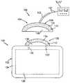
- FIG. 1is a bottom plan view of a return pad and an electrode cable connector in accordance with the present disclosure
- FIG. 2is a perspective view of a return pad and an electrode cable connector in accordance with an alternative embodiment of the present disclosure
- FIG. 3is a perspective view of a return pad and an electrode cable connector in accordance with yet another embodiment of the present disclosure
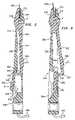
- FIG. 4is an exploded, perspective view of a return pad and an electrode cable connector similar to the embodiments shown in FIG. 3 ;
- FIG. 5is a cross-sectional side elevational view of the electrode connector of FIG. 4 shown in the closed position;
- FIG. 6is a cross-sectional side elevational view of the electrode connector of FIG. 4 shown in the open position
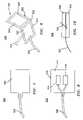
- FIG. 7is a top plan view of an electrode cable connector in accordance with an alternative embodiment of the present disclosure.
- FIG. 8is a top plan view of an electrode cable connector in accordance with yet another embodiment of the present disclosure.
- FIG. 9is a perspective view of an electrode cable connector in accordance with still another embodiment of the present disclosure.
- FIG. 10is a side elevational view of an electrode cable connector of FIG. 9 illustrating a preferred method of coupling of a magnet to a substrate thereof.
- Cable connector 100includes a reusable conductive wire cable 102 which operatively couples at a proximal end thereof to an electrosurgical generator “E/S” and a reusable cord-to-pad interface 104 which is disposed at a distal end thereof.
- Cord-to-pad interface 104includes an insulated backing 106 having a conductive cord surface 108 disposed thereon which electrically couples to a wire 107 passing through cable 102 .
- An adhesive border 110is defined about the outer periphery of the conductive cord surface 108 . It is contemplated that conductive cord surface 108 may be positioned along one edge of cord-to-pad interface 104 to facilitate connection with the return pad 120 . However, it is also envisioned that the conductive cord surface 108 or multiple conductive cord surfaces 108 may be arranged anywhere on the surface of the cord-to-pad interface 104 depending upon a particular purpose orto facilitate electrical engagement.
- the adhesive border 110includes a non-conductive adhesive 112 applied thereto which reduces stray electrical current from emanating from the conductive cord surface 108 . While application of non-conductive adhesive 112 to adhesive border 110 is preferred, it is envisioned that adhesive border 110 may stand alone without adding the non-conductive adhesive 112 .
- cable connector 100is configured and adapted to be removably adhered to a return pad or return electrode 120 .
- Return pad 120includes an insulated backing 122 , an insulated cover 124 and a conventional electrically conductive member 126 retained between insulated backing 122 and insulated cover 124 .
- Insulated backing 122includes a pad-to-cord interface 128 which extends from a side surface thereof.
- Pad-to-cord interface 128includes a conductive pad surface 130 , preferably made from an electrically conductive material, disposed thereon which electrically couples return pad 120 to the conductive cord surface 108 .
- Conductive pad surface 130is electrically connected to conductive member 126 (via at least one conductive wire 132 which is disposed between backing 122 and cover 124 ).
- An adhesive border 134is defined about the outer periphery of the conductive pad surface 130 . It is contemplated that conductive pad surface 130 is positioned to compliment the particular arrangements of conductive surface(s) 108 on the cord-to-pad interfaces. Much like adhesive border 110 , adhesive border 134 may also include a non-conductive adhesive 112 applied thereto to facilitate engagement and reduce stray electrical currents.
- non-conductive adhesive 112While application of non-conductive adhesive 112 to adhesive border 134 of pad-to-cord interface 128 is preferred, the non-conductive adhesive 112 need not be applied to adhesive border 134 especially if the non-conductive adhesive 112 is provided on adhesive border 110 of cord-to-pad interface 104 . It is further envisioned, that if the non-conductive adhesive 112 is provided on return pad 120 along adhesive border 134 of pad-to-cord interface 128 , no adhesive, either conductive or non-conductive, need be provided on adhesive border 110 of cord-to-pad interface 104 .
- a non-conductive adhesive for adhering adhesive border 110 of cord-to-pad interface 104 to adhesive border 134 of pad-to-cord interface 128is disclosed in commonly owned U.S. Pat. No. 4,699,146 to Sieverding, the entire contents of which are incorporated herein by reference.
- cord-to-pad interface 104is adhered to pad-to-cord interface 128 by applying the non-conductive adhesive 112 to their respective adhesive borders 110 and 134 and pressing the two interfaces together. In this manner, conductive cord surface 108 directly contacts conductive pad surface 130 thereby establishing an electrical connection therebetween.
- Cable connector 200includes a reusable conductive wire cable 202 having a typical connector 204 attached to a proximal end thereof for interfacing cable 202 with an electrosurgical generator (not shown) and a reusable cord-to-pad interface 206 operatively coupled to a distal end thereof.
- Cord-to-pad interface 206includes an insulated backing 208 having a pair of conductive cord surfaces 210 a , 210 b disposed thereon which electrically couple to a wire 212 passing through cable 202 .
- Conductive cord surfaces 210 a , 210 bare preferably spaced from one another and extend distally along a top surface 211 of cord-to-pad interface 206 .
- An adhesive border 214is defined about the periphery of each conductive cord surface 210 a , 210 b .
- Adhesive border 214may include a non-conductive adhesive 216 applied thereto in order to facilitate mechanical connection with return pad 220 .
- a conductive adhesive 218 a , 218 bis applied to each conductive cord surface 210 a , 210 b , respectively.
- cable connector 200is configured and adapted to be removably adhered to return pad 220 .
- Return pad 220is similar to return pad 120 of FIG. 1 but includes a pair of complimentary conductive surfaces 230 a , 230 b which electrically couple with conductive pad surfaces 210 a , 210 b , respectively.
- Each conductive surface 230 a , 230 bis coupled to a conductive member 236 a , 236 b disposed within the return pad 220 .
- return pad 220includes an insulated backing 222 having a pad-to-cord interface 228 which extends from a side surface thereof.
- Pad-to-cord interface 228includes the pad conductive surfaces 230 a , 230 b disposed thereon which couple with conductive cord surfaces 210 a , 210 b .
- An adhesive border 234surrounds the periphery of each conductive pad surface 230 .
- Adhesive border 234is configured to include a non-conductive adhesive 216 applied thereto which reduces stray current which may emanate from the conductive surfaces.
- a conductive adhesive 218and covers each conductive pad surface 230 a , 230 b to facilitate and maintain electrical connection with conductive cord surfaces 210 a , 210 b.
- a conductive adhesive 218is selected such that the conductivity of the adhesive will be sufficient for the electrosurgical power to be conducted through the small area of the attachment as well as provide impedance low enough for contact quality monitoring in the generator. While a non-conductive and a conductive adhesive have been contemplated for use in the present embodiment, it is envisioned that a single conductive adhesive can be applied to both adhesive borders 214 and 234 as well as to both conductive surfaces 210 a , 210 b and 230 a , 230 b . Adhesive 218 a , 218 b is selected such that the electro-conductivity of the adhesive promotes the transfer of electric signals between conductive surfaces 210 a , 210 b and 230 a , 230 b.
- a non-conductive or conductive adhesivemay only be applied to conductive surface 210 a , 210 b , 230 a and 230 b or, alternatively, a non-conductive or a conductive adhesive may only be applied to adhesive borders 214 , 234 . It is further envisioned that adhesive does not have to be provided on conductive surfaces 210 a , 210 b , 230 a or 230 b and an adhesive may be solely applied to one of the adhesive borders 214 , 234 , preferably adhesive border 234 of return pad 220 .
- a return pad cable connectoris shown in accordance with another embodiment of the present disclosure and is generally identified as 300 .
- Cable connector 300includes two major subunits; a base element 302 and a return pad clamp 304 (see FIG. 4 ).
- base element 302 and return pad clamp 304cooperate to grip the return pad 400 .
- both base element 302 and return pad clamp 304are preferably molded from a strong, resilient plastic material, such as acetal resin.
- Base element 302includes a return pad interface 306 and a handle 308 .
- handle 308is dimensioned to facilitate gripping and may be ergonomically shaped to enhance “feel”.
- Return pad interface 306preferably includes a fixed jaw 312 having an L-shaped cross-section defined by a first leg 310 for housing a series of pivot mounts 336 disposed therein and a second leg 311 which vertically extends therefrom which cooperates with the pad clamp 304 to secure the return pad 400 as explained in more detail below.
- a lever housing 314is formed in the pad interface 306 and operates to mechanically align and secure the pad clamp 304 with handle 308 . More particularly, a locking aperture 316 extends through handle 308 and is located toward the distal end of the same ( 308 ). As explained in more detail below, locking aperture 316 and lever housing 314 cooperate to align and secure the pad clamp 304 within handle 308 .
- Return pad clamp 304includes a movable jaw 318 and a clamping lever 320 which depends from movable jaw 318 and which is designed to mechanically engage handle 308 .
- Clamping lever 320includes a proximal half 322 having an offset 324 which extends at an angle relative to proximal half 322 .
- a distal half 326depends from offset 324 such that proximal half 322 , offset 324 and distal half 326 form a generally reverse “S” configuration which facilitates assembly of the cable connector 300 .
- the proximal and distal halves 322 and 326are generally parallel to one another and offset 324 is disposed perpendicular thereto.
- Movable jaw 318also includes a series of pivot projections 334 which are designed for mechanical engagement with pivot mounts 336 as discussed below.
- a locking pivot grip 328is disposed on the proximal half 322 of the return pad clamp 304 and a corresponding unlocking pivot grip 330 is formed on the distal half 326 .
- the locking and unlocking pivot grips 328 and 330are designed to facilitate movement of clamping lever 320 by an operator's finger to mechanically move/pivot jaw member 318 from a first open position for reception of the return pad 400 to the second locking position which secures the return pad 400 in electromechanical engagement with the cable connector 300 .
- Return pad clamp 304is pivotally mounted to base element 302 so that movable jaw 318 lies in registration with fixed jaw 312 and pivots about an axis “A” (see FIGS. 5 and 6 ) defined through first leg 310 of the return pad interface 306 . More particularly, the return pad clamp 304 is mounted by passing clamping lever 320 through lever housing 314 and engaging the pivot projections 334 within the corresponding pivot mounts 336 disposed in first leg 310 .
- Clamping lever 320 when mountedextends along handle 308 , preferably lying in a channel 338 defined therein. More particularly, clamping lever 320 , when mounted, extends through lever housing 314 and to locking aperture 316 such that the distal half 326 is movable within locking aperture 316 from a first locking position wherein movable jaw is secured tot he return pad 400 (see FIG. 5 ) to a second open position for disengaging the return pad 400 (see FIG. 6 ).
- locking aperture 316is designed to accept and cooperate with clamping lever 320 in the manner described above.
- locking aperture 316is generally keyhole shaped, with a rectangular portion designed to accommodate distal half 326 of clamping lever 320 , and a circular, chamfered thumb well 340 which surrounds un-locking grip 330 .
- the length of offset 324is preferably dimensioned to allow proximal half 322 to lie generally flush with the outer surface of handle 308 when clamping lever 320 is disposed in the “locked” position. Also, when locked, distal half 326 is generally flush with the opposite surface of handle 308 .
- a locking rail 342is disposed within locking aperture 316 and is designed to mechanically engage a corresponding latch 332 disposed on offset 324 to secure clamping lever 320 in a “locked” position which, in turn, locks the cable connector 300 to the return pad 400 .
- cooperation between locking rail 342 and latch 332is made possible by dimensioning clamping lever 320 such that the distance from axis A to the tip of latch 332 is slightly less than the distance from that point to the tip of locking rail 342 .
- base element 302also includes a conductive surface 344 affixed to an inner facing surface of fixed jaw 312 which couples with a conductive wire 346 extending from handle 308 to the electrosurgical generator (not shown).
- Return pad 400includes an insulated backing 402 , an insulated cover 404 and a conventional electrically conductive member 406 retained between insulated backing 402 and insulated cover 404 .
- Insulated backing 402includes a pad-to-cord connector 408 extending from a side surface thereof.
- Pad-to-cord connector 408includes a conductive pad surface 410 disposed thereon for electrically connecting return pad 400 to conductive surface 344 of connector 300 .
- Conductive pad surface 410is electrically connected to conductive member 406 via a conductive path 412 .
- An adhesive border 414surrounds conductive pad surface 410 and is configured such that a non-conductive adhesive 416 can be applied thereto. It is contemplated that a conductive adhesive can be applied between conductive surface 344 of connector 300 and pad conductive surface 410 to assure electrical continuity between the same.
- connector 300firmly holds return pad 400 between fixed and movable jaws 312 and 318 , respectively, via the mechanically cooperative action of latch 332 and locking rail 342 .
- conductive surface 344 of connector 300 and conductive pad surface 410 of return pad 400are held in electrical contact with one another.
- movable jaw 318is rotated away from fixed jaw 312 , permitting insertion and removal of return pad 400 therefrom.
- FIGS. 5 and 6Movement between the open and the closed/locked positions is shown in FIGS. 5 and 6 .
- the operatorapplies a force in the direction “D” to unlocking grip 330 , preferably by pressing with a thumb or finger.
- the distal half 326 and latch 332unlocks causing the movable jaw 318 of clamping member 320 to pivot away from fixed jaw 312 and release pad 400 .
- offset 324rotates upward, forcing the proximal half 322 out of channel 338 .
- applying a force in the direction “D”rotates the pivot projections 334 within pivot mounts 336 to cause movable jaw 318 to open.
- the return pad 400is either released or a new return pad may be positioned therein.
- the connector 300can be locked. Locking of connector 300 involves applying a force in a direction “C” to locking grip 328 . This forces latch 332 against locking rail 342 , causing proximate leg 322 to flex and rotate latch 332 beyond locking rail 342 thus moving clamp lever 320 to a “locked” position (see FIG. 5 ). In turn, the pivot projections of moveable jaw 318 are rotated within pivot mounts 336 of fixed jaw 316 thereby securing return pad 400 between the jaw members 312 , 318 .
- each jaw member 312 , 318may be provided with a plurality of teeth 317 formed on either conductive surface 344 of connector 300 , the non-conductive surface of second leg 311 of fixed jaw 312 or both. Accordingly, the plurality of teeth 317 increases the retention of pad-to-chord connector 408 of return pad 400 therebetween.
- return pad cable connector 500in shown in accordance with the principles of the present disclosure and is generally identified as 500 .
- return pad cable connector 500is configured and adapted to cooperate with a return electrode 120 as generally described above.
- return pad cable connector 500includes a conductive return wire cable 502 , operatively coupled at a proximal end thereof to an electrosurgical generator (not shown), and a cord-to-pad interface 504 operatively coupled to a distal end thereof.
- cord-to-pad interface 504is made of an electrically conductive magnetic material. Accordingly, when cord-to-pad interface 504 is approximated toward or brought into contact with conductive pad surface 130 of return pad 120 , interface 504 will magnetically couple with conductive pad surface 130 . As such, the contact between cord-to-pad interface 504 and conductive pad surface 130 will return energy during electrosurgical procedures, from return pad 120 to the electrosurgical generator (not shown).
- return pad cable connector 500includes a conductive return wire cable 502 , operatively coupled at a proximal end thereof to an electrosurgical generator (not shown), and a cord-to-pad interface 510 operatively coupled to a distal end thereof.
- cord-to-pad interface 510includes a magnetic substrate 512 having at least one electrical contact 514 disposed thereon, wherein wire cable 502 is electrically coupled to electrical contact(s) 514 . It is envisioned that magnetic substrate 512 can be made from either conductive or non-conductive materials.
- cord-to-pad interface 510when cord-to-pad interface 510 is approximated toward or brought into contact with conductive pad surface 130 of return pad 120 , such that the at least one electrical contact 514 will be brought into contact with conductive pad surface 130 , interface 510 will magnetically couple with conductive pad surface 130 . As such, the contact between cord-to-pad interface 510 and conductive pad surface 130 will return energy during electrosurgical procedures, from return pad 120 to the electrosurgical generator (not shown).
- return pad cable connector 500includes a conductive return wire cable 502 , operatively coupled at a proximal end thereof to an electrosurgical generator (not shown), and a cord-to-pad interface 520 operatively coupled to a distal end thereof.
- Cord-to-pad interface 520includes a flexible substrate 522 having a first portion 524 and a second portion 526 integrally connected to first portion 524 to thereby define a fold line 528 .
- Cord-to-pad interface 520further includes an electrically conductive magnet 530 provided on each of first and second portions 524 , 526 of substrate 522 , wherein wire cable 502 is electrically coupled to one of the pair of magnets 530 .
- magnet 530While a pair of electrically conductive magnets 530 is disclosed, it is contemplated that only magnet 530 , which is electrically coupled to wire cable 502 , needs to be made from an electrically conductive material while the other magnet can be made from non-conductive materials. It is further envisioned that, if both magnets 530 are non-conductive, an electrical contact (not shown) can be disposed on magnet 530 which is electrical contact is electrically coupled to wire cable 502 .
- wire cable 502can extend from return pad cable connector 500 from a side of substrate 522 which is parallel to fold line 528 , or in the alternative, as shown in phantom, wire cable 502 can extend from return pad cable connector 500 from a side of substrate 522 which is transverse to fold line 528 .
- return pad cable connector 500requires that after conductive pad surface 130 of return pad 120 is brought into contact with magnet 530 with is electrically coupled to wire cable 502 , flexible substrate 522 is folded along fold line 528 in order to approximate magnets 530 of first and second portions 524 , 526 toward one another thereby sandwiching conductive pad surface 130 therebetween. As such, the contact between magnet 530 , coupled to wire cable 502 , and conductive pad surface 130 will return energy during electrosurgical procedures, from return pad 120 to the electrosurgical generator (not shown).
- a preferred method of coupling a magnet to a substrate for a return pad cable connector 500is illustrated.
- a magnet 540overlies a substrate 542 and at least one retaining device 544 (i.e., a pin) is used to pass though magnet 540 and imbedded in substrate 542 to secure magnet 540 to substrate 542 .
- wire cable 502can be disposed between magnet 540 and substrate 542 . While a pin has been disclosed it is envisioned that other methods of coupling the magnet to a substrate can be used, such as, for example, an adhesive, screws, clips, clamps and the like.
- return pad cable connector 500results in easier attachment and removal of return pad cable connector 500 from conductive pad surface 130 of return pad 120 as well as easier cleaning of the contact surfaces and a lower profile.
- return pad cable connector 500can be used in combination with a conductive adhesive disposed between return pad cable connector 500 and conductive pad surface 130 .
Landscapes
- Health & Medical Sciences (AREA)
- Engineering & Computer Science (AREA)
- Life Sciences & Earth Sciences (AREA)
- Biomedical Technology (AREA)
- Animal Behavior & Ethology (AREA)
- Veterinary Medicine (AREA)
- Surgery (AREA)
- Nuclear Medicine, Radiotherapy & Molecular Imaging (AREA)
- Public Health (AREA)
- General Health & Medical Sciences (AREA)
- Plasma & Fusion (AREA)
- Molecular Biology (AREA)
- Medical Informatics (AREA)
- Heart & Thoracic Surgery (AREA)
- Physics & Mathematics (AREA)
- Otolaryngology (AREA)
- Radiology & Medical Imaging (AREA)
- Surgical Instruments (AREA)
Abstract
Description
Claims (16)
Priority Applications (1)
| Application Number | Priority Date | Filing Date | Title |
|---|---|---|---|
| US11/243,886US7229307B2 (en) | 2001-06-01 | 2005-10-04 | Return pad cable connector |
Applications Claiming Priority (5)
| Application Number | Priority Date | Filing Date | Title |
|---|---|---|---|
| US29517601P | 2001-06-01 | 2001-06-01 | |
| PCT/US2002/017360WO2002099442A2 (en) | 2001-06-01 | 2002-05-31 | Return pad cable connector |
| US10/369,896US6796828B2 (en) | 2001-06-01 | 2003-02-20 | Return pad cable connector |
| US10/919,612US6997735B2 (en) | 2001-06-01 | 2004-08-17 | Return pad cable connector |
| US11/243,886US7229307B2 (en) | 2001-06-01 | 2005-10-04 | Return pad cable connector |
Related Parent Applications (1)
| Application Number | Title | Priority Date | Filing Date |
|---|---|---|---|
| US10/919,612ContinuationUS6997735B2 (en) | 2001-06-01 | 2004-08-17 | Return pad cable connector |
Publications (2)
| Publication Number | Publication Date |
|---|---|
| US20060030195A1 US20060030195A1 (en) | 2006-02-09 |
| US7229307B2true US7229307B2 (en) | 2007-06-12 |
Family
ID=34277870
Family Applications (3)
| Application Number | Title | Priority Date | Filing Date |
|---|---|---|---|
| US10/369,896Expired - LifetimeUS6796828B2 (en) | 2001-06-01 | 2003-02-20 | Return pad cable connector |
| US10/919,612Expired - LifetimeUS6997735B2 (en) | 2001-06-01 | 2004-08-17 | Return pad cable connector |
| US11/243,886Expired - LifetimeUS7229307B2 (en) | 2001-06-01 | 2005-10-04 | Return pad cable connector |
Family Applications Before (2)
| Application Number | Title | Priority Date | Filing Date |
|---|---|---|---|
| US10/369,896Expired - LifetimeUS6796828B2 (en) | 2001-06-01 | 2003-02-20 | Return pad cable connector |
| US10/919,612Expired - LifetimeUS6997735B2 (en) | 2001-06-01 | 2004-08-17 | Return pad cable connector |
Country Status (1)
| Country | Link |
|---|---|
| US (3) | US6796828B2 (en) |
Cited By (26)
| Publication number | Priority date | Publication date | Assignee | Title |
|---|---|---|---|---|
| US20070073284A1 (en)* | 2002-09-25 | 2007-03-29 | Sturm Thomas A | Multiple RF return pad contact detection system |
| US20080110672A1 (en)* | 2007-11-08 | 2008-05-15 | Todd Ryan | Magnetic Mount for an Electronic Device |
| US7473145B2 (en) | 2001-06-01 | 2009-01-06 | Covidien Ag | Return pad cable connector |
| US7637907B2 (en) | 2006-09-19 | 2009-12-29 | Covidien Ag | System and method for return electrode monitoring |
| US7722603B2 (en) | 2006-09-28 | 2010-05-25 | Covidien Ag | Smart return electrode pad |
| US7736359B2 (en) | 2006-01-12 | 2010-06-15 | Covidien Ag | RF return pad current detection system |
| US7927329B2 (en) | 2006-09-28 | 2011-04-19 | Covidien Ag | Temperature sensing return electrode pad |
| US20110178517A1 (en)* | 2008-10-01 | 2011-07-21 | Beller Juergen | Electrosurgical hf generator |
| US8021360B2 (en) | 2007-04-03 | 2011-09-20 | Tyco Healthcare Group Lp | System and method for providing even heat distribution and cooling return pads |
| US8080007B2 (en) | 2007-05-07 | 2011-12-20 | Tyco Healthcare Group Lp | Capacitive electrosurgical return pad with contact quality monitoring |
| US8100898B2 (en) | 2007-08-01 | 2012-01-24 | Tyco Healthcare Group Lp | System and method for return electrode monitoring |
| US8231614B2 (en) | 2007-05-11 | 2012-07-31 | Tyco Healthcare Group Lp | Temperature monitoring return electrode |
| US8388612B2 (en) | 2007-05-11 | 2013-03-05 | Covidien Lp | Temperature monitoring return electrode |
| US8551088B2 (en) | 2008-03-31 | 2013-10-08 | Applied Medical Resources Corporation | Electrosurgical system |
| US8777940B2 (en) | 2007-04-03 | 2014-07-15 | Covidien Lp | System and method for providing even heat distribution and cooling return pads |
| US8801703B2 (en) | 2007-08-01 | 2014-08-12 | Covidien Lp | System and method for return electrode monitoring |
| US8808161B2 (en) | 2003-10-23 | 2014-08-19 | Covidien Ag | Redundant temperature monitoring in electrosurgical systems for safety mitigation |
| US8821487B2 (en) | 2005-03-31 | 2014-09-02 | Covidien Ag | Temperature regulating patient return electrode and return electrode monitoring system |
| USD748259S1 (en) | 2014-12-29 | 2016-01-26 | Applied Medical Resources Corporation | Electrosurgical instrument |
| US9320563B2 (en) | 2010-10-01 | 2016-04-26 | Applied Medical Resources Corporation | Electrosurgical instruments and connections thereto |
| US10149713B2 (en) | 2014-05-16 | 2018-12-11 | Applied Medical Resources Corporation | Electrosurgical system |
| US10420603B2 (en) | 2014-12-23 | 2019-09-24 | Applied Medical Resources Corporation | Bipolar electrosurgical sealer and divider |
| US10792092B2 (en) | 2014-05-30 | 2020-10-06 | Applied Medical Resources Corporation | Electrosurgical seal and dissection systems |
| US11283213B2 (en) | 2016-06-17 | 2022-03-22 | Megadyne Medical Products, Inc. | Cable connection systems for electrosurgical systems |
| US11696796B2 (en) | 2018-11-16 | 2023-07-11 | Applied Medical Resources Corporation | Electrosurgical system |
| US11864812B2 (en) | 2018-09-05 | 2024-01-09 | Applied Medical Resources Corporation | Electrosurgical generator control system |
Families Citing this family (21)
| Publication number | Priority date | Publication date | Assignee | Title |
|---|---|---|---|---|
| US6796828B2 (en)* | 2001-06-01 | 2004-09-28 | Sherwood Services Ag | Return pad cable connector |
| WO2005070494A1 (en) | 2004-01-22 | 2005-08-04 | Rehabtronics Inc. | Method of routing electrical current to bodily tissues via implanted passive conductors |
| US7771419B2 (en)* | 2004-10-05 | 2010-08-10 | Granite Advisory Services, Inc. | Biomedical dispersive electrode |
| WO2006136661A1 (en)* | 2005-06-21 | 2006-12-28 | Seven Networks International Oy | Network-initiated data transfer in a mobile network |
| EP1899002A1 (en) | 2005-06-28 | 2008-03-19 | Bioness Development, Llc | Improvements to an implant, system and method using implanted passive conductors for routing electrical current |
| US20070049914A1 (en)* | 2005-09-01 | 2007-03-01 | Sherwood Services Ag | Return electrode pad with conductive element grid and method |
| US20070167942A1 (en)* | 2006-01-18 | 2007-07-19 | Sherwood Services Ag | RF return pad current distribution system |
| US20070244478A1 (en)* | 2006-04-18 | 2007-10-18 | Sherwood Services Ag | System and method for reducing patient return electrode current concentrations |
| US20080009846A1 (en)* | 2006-07-06 | 2008-01-10 | Sherwood Services Ag | Electrosurgical return electrode with an involuted edge |
| US8708210B2 (en)* | 2006-10-05 | 2014-04-29 | Covidien Lp | Method and force-limiting handle mechanism for a surgical instrument |
| US8169329B2 (en)* | 2007-03-19 | 2012-05-01 | Arthur Koblasz | Fluid detecting mattress cover and monitoring system |
| US20080249524A1 (en)* | 2007-04-03 | 2008-10-09 | Tyco Healthcare Group Lp | System and method for providing even heat distribution and cooling return pads |
| US7442042B1 (en) | 2007-07-09 | 2008-10-28 | Lewis Justin A | Magnetic clip cord |
| US9757554B2 (en) | 2007-08-23 | 2017-09-12 | Bioness Inc. | System for transmitting electrical current to a bodily tissue |
| US8738137B2 (en)* | 2007-08-23 | 2014-05-27 | Bioness Inc. | System for transmitting electrical current to a bodily tissue |
| US7969715B2 (en)* | 2007-11-13 | 2011-06-28 | Eikon Device Inc. | Power supply for a tattoo machine |
| US20090326602A1 (en) | 2008-06-27 | 2009-12-31 | Arkady Glukhovsky | Treatment of indications using electrical stimulation |
| US20110238058A1 (en)* | 2010-03-29 | 2011-09-29 | Estech, Inc. (Endoscopic Technologies, Inc.) | Indifferent electrode pad systems and methods for tissue ablation |
| US9888954B2 (en) | 2012-08-10 | 2018-02-13 | Cook Medical Technologies Llc | Plasma resection electrode |
| US10624804B2 (en) | 2015-08-18 | 2020-04-21 | Hill-Rom Services, Inc. | Microclimate management airflow control based on incontinence detection |
| US11065461B2 (en) | 2019-07-08 | 2021-07-20 | Bioness Inc. | Implantable power adapter |
Citations (96)
| Publication number | Priority date | Publication date | Assignee | Title |
|---|---|---|---|---|
| US3543760A (en) | 1968-03-11 | 1970-12-01 | Medical Plastic Inc | Disposable ground plate electrode |
| US3812861A (en) | 1972-11-15 | 1974-05-28 | R Peters | Disposable electrode |
| FR2276027A1 (en) | 1974-06-25 | 1976-01-23 | Medical Plastics Inc | Plate electrode with connector - is clamped between connector jaws held by releasable locking device |
| US3987796A (en) | 1974-04-18 | 1976-10-26 | Dentsply Research & Development Corporation | Electrosurgical device |
| US4067342A (en)* | 1976-04-06 | 1978-01-10 | Medtronic, Inc. | Tape electrode |
| US4092985A (en) | 1974-11-25 | 1978-06-06 | John George Kaufman | Body electrode for electro-medical use |
| US4114622A (en) | 1975-07-02 | 1978-09-19 | Dentsply Research And Development Corporation | Electrosurgical device |
| US4117846A (en) | 1976-05-07 | 1978-10-03 | Consolidated Medical Equipment | Skin conducting electrode and electrode assembly |
| US4121590A (en) | 1977-03-14 | 1978-10-24 | Dentsply Research And Development Corporation | System for monitoring integrity of a patient return circuit |
| US4200104A (en) | 1977-11-17 | 1980-04-29 | Valleylab, Inc. | Contact area measurement apparatus for use in electrosurgery |
| US4213463A (en) | 1978-07-24 | 1980-07-22 | Graphic Controls Corporation | Body electrode with indicator to ensure optimal securement |
| US4237887A (en) | 1975-01-23 | 1980-12-09 | Valleylab, Inc. | Electrosurgical device |
| US4253721A (en) | 1979-09-24 | 1981-03-03 | Kaufman John George | Cable connector |
| US4303073A (en) | 1980-01-17 | 1981-12-01 | Medical Plastics, Inc. | Electrosurgery safety monitor |
| US4304235A (en) | 1978-09-12 | 1981-12-08 | Kaufman John George | Electrosurgical electrode |
| US4331149A (en) | 1975-01-23 | 1982-05-25 | Dentsply Research And Development Corp. | Electrosurgical device |
| US4343308A (en) | 1980-06-09 | 1982-08-10 | Gross Robert D | Surgical ground detector |
| US4416276A (en) | 1981-10-26 | 1983-11-22 | Valleylab, Inc. | Adaptive, return electrode monitoring system |
| US4416277A (en) | 1981-11-03 | 1983-11-22 | Valleylab, Inc. | Return electrode monitoring system for use during electrosurgical activation |
| US4643193A (en) | 1985-06-04 | 1987-02-17 | C. R. Bard, Inc. | ECG electrode with sensing element having a conductive coating in a pattern thereon |
| US4669468A (en) | 1979-06-15 | 1987-06-02 | American Hospital Supply Corporation | Capacitively coupled indifferent electrode |
| US4699146A (en) | 1982-02-25 | 1987-10-13 | Valleylab, Inc. | Hydrophilic, elastomeric, pressure-sensitive adhesive |
| US4722761A (en) | 1986-03-28 | 1988-02-02 | Baxter Travenol Laboratories, Inc. | Method of making a medical electrode |
| US4741334A (en) | 1985-05-07 | 1988-05-03 | Werner Irnich | Monitoring arrangement for a high frequency surgery device |
| US4748983A (en)* | 1985-08-27 | 1988-06-07 | Kureha Kagaku Kogyo Kabushiki Kaisha | X-ray transmissive electrode for a living body |
| US4750482A (en) | 1982-02-25 | 1988-06-14 | Pfizer Inc. | Hydrophilic, elastomeric, pressure-sensitive adhesive |
| US4754757A (en) | 1985-12-16 | 1988-07-05 | Peter Feucht | Method and apparatus for monitoring the surface contact of a neutral electrode of a HF-surgical apparatus |
| US4768514A (en) | 1985-06-04 | 1988-09-06 | C. R. Bard, Inc. | Medical electrode |
| US4799480A (en) | 1987-08-04 | 1989-01-24 | Conmed | Electrode for electrosurgical apparatus |
| US4848335A (en) | 1988-02-16 | 1989-07-18 | Aspen Laboratories, Inc. | Return electrode contact monitor |
| US4873974A (en) | 1987-09-11 | 1989-10-17 | Siemens Aktiengesellschaft | Neutral electrode for a high-frequency surgical instrument |
| US4895169A (en)* | 1980-08-08 | 1990-01-23 | Darox Corporation | Disposable non-invasive stimulating electrode set |
| US4947846A (en) | 1987-06-13 | 1990-08-14 | Tdk Corporation | Waterproof electrode device for a living body |
| US4955381A (en) | 1988-08-26 | 1990-09-11 | Cardiotronics, Inc. | Multi-pad, multi-function electrode |
| US5004425A (en)* | 1989-10-10 | 1991-04-02 | Jes, L.P. | Magnetic snap assembly for connecting grounding cord to electrically conductive body band |
| US5010896A (en)* | 1989-10-17 | 1991-04-30 | Westec Corporation | Pulsed galvanic stimulator |
| US5042981A (en) | 1986-06-25 | 1991-08-27 | Fuchelman Sociedad Anonima | Assembly comprising a surgical drape and a contour-type electrosurgical dispersive electrode, and method for its use |
| US5087257A (en) | 1989-04-01 | 1992-02-11 | Erbe Elektromedizin Gmbh | Apparatus for monitoring the application of neutral electrodes on a patient undergoing high frequency electro-surgery |
| US5196008A (en) | 1989-09-07 | 1993-03-23 | Siemens Aktiengesellschaft | Method and circuit for monitoring electrode surfaces at the body tissue of a patient in an hf surgery device |
| US5276079A (en) | 1991-11-15 | 1994-01-04 | Minnesota Mining And Manufacturing Company | Pressure-sensitive poly(n-vinyl lactam) adhesive composition and method for producing and using same |
| US5362420A (en) | 1991-11-15 | 1994-11-08 | Minnesota Mining And Manufacturing Company | Low impedance pressure sensitive adhesive composition and biomedical electrodes using same |
| US5385679A (en) | 1991-11-15 | 1995-01-31 | Minnesota Mining And Manufacturing | Solid state conductive polymer compositions, biomedical electrodes containing such compositions, and method of preparing same |
| US5388490A (en) | 1990-05-10 | 1995-02-14 | Buck; Byron L. | Rotary die cutting system and method for sheet material |
| US5496363A (en)* | 1993-06-02 | 1996-03-05 | Minnesota Mining And Manufacturing Company | Electrode and assembly |
| US5496312A (en) | 1993-10-07 | 1996-03-05 | Valleylab Inc. | Impedance and temperature generator control |
| US5540684A (en) | 1994-07-28 | 1996-07-30 | Hassler, Jr.; William L. | Method and apparatus for electrosurgically treating tissue |
| US5611709A (en) | 1995-08-10 | 1997-03-18 | Valleylab Inc | Method and assembly of member and terminal |
| US5660892A (en) | 1993-05-14 | 1997-08-26 | Minnesota Mining And Manufacturing Company | Method of forming a metallic film |
| US5670557A (en) | 1994-01-28 | 1997-09-23 | Minnesota Mining And Manufacturing Company | Polymerized microemulsion pressure sensitive adhesive compositions and methods of preparing and using same |
| US5674561A (en) | 1994-01-28 | 1997-10-07 | Minnesota Mining And Manufacturing Company | Polymerized microemulsion pressure sensitive adhesive compositions and methods of preparing and using same |
| US5678545A (en) | 1995-05-04 | 1997-10-21 | Stratbucker; Robert A. | Anisotropic adhesive multiple electrode system, and method of use |
| US5695494A (en) | 1994-12-22 | 1997-12-09 | Valleylab Inc | Rem output stage topology |
| US5707369A (en) | 1995-04-24 | 1998-01-13 | Ethicon Endo-Surgery, Inc. | Temperature feedback monitor for hemostatic surgical instrument |
| US5720744A (en) | 1995-06-06 | 1998-02-24 | Valleylab Inc | Control system for neurosurgery |
| EP0836868A2 (en) | 1996-10-18 | 1998-04-22 | Gebr. Berchtold GmbH & Co. | High frequency surgical apparatus and method for operating same |
| WO1998018395A1 (en) | 1996-10-30 | 1998-05-07 | Megadyne Medical Products, Inc. | Capacitive reusable electrosurgical return electrode |
| US5766165A (en) | 1995-09-22 | 1998-06-16 | Gentelia; John S. | Return path monitoring system |
| US5797902A (en) | 1996-05-10 | 1998-08-25 | Minnesota Mining And Manufacturing Company | Biomedical electrode providing early detection of accidental detachment |
| US5830212A (en) | 1996-10-21 | 1998-11-03 | Ndm, Inc. | Electrosurgical generator and electrode |
| DE19717411A1 (en) | 1997-04-25 | 1998-11-05 | Aesculap Ag & Co Kg | Monitoring of thermal loading of patient tissue in contact region of neutral electrode of HF treatment unit |
| US5836942A (en) | 1996-04-04 | 1998-11-17 | Minnesota Mining And Manufacturing Company | Biomedical electrode with lossy dielectric properties |
| WO1998053751A1 (en) | 1997-05-30 | 1998-12-03 | Goldberg S Nahum | System and method for performing plate type radiofrequency ablation |
| US5846558A (en) | 1996-03-19 | 1998-12-08 | Minnesota Mining And Manufacturing Company | Ionically conductive adhesives prepared from zwitterionic materials and medical devices using such adhesives |
| US5868742A (en) | 1995-10-18 | 1999-02-09 | Conmed Corporation | Auxiliary reference electrode and potential referencing technique for endoscopic electrosurgical instruments |
| WO1999011187A1 (en) | 1997-08-29 | 1999-03-11 | Minnesota Mining And Manufacturing Company | Method and apparatus for detecting loss of contact of biomedical electrodes with patient skin |
| DE19801173C1 (en) | 1998-01-15 | 1999-07-15 | Kendall Med Erzeugnisse Gmbh | Clamp connector for film electrodes |
| US5924983A (en) | 1996-04-29 | 1999-07-20 | Minnesota Mining And Manufacturing Company | Electrical conductor for biomedical electrodes and biomedical electrodes prepared therefrom |
| US5947961A (en) | 1996-05-10 | 1999-09-07 | Minnesota Mining And Manufacturing Company | Biomedical electrode having skin-equilibrating adhesive at its perimeter and method for using same |
| US5985990A (en) | 1995-12-29 | 1999-11-16 | 3M Innovative Properties Company | Use of pendant free-radically polymerizable moieties with polar polymers to prepare hydrophilic pressure sensitive adhesive compositions |
| US5999061A (en) | 1998-05-05 | 1999-12-07 | Vari-L Company, Inc. | First and second oscillator circuits selectively coupled through passive output circuit to a load |
| US6030381A (en) | 1994-03-18 | 2000-02-29 | Medicor Corporation | Composite dielectric coating for electrosurgical implements |
| US6032063A (en) | 1997-12-09 | 2000-02-29 | Vital Connections, Inc. | Distributed resistance leadwire harness assembly for physiological monitoring during magnetic resonance imaging |
| WO2000032122A1 (en) | 1998-11-30 | 2000-06-08 | Megadyne Medical Products, Inc. | Resistive reusable electrosurgical return electrode |
| US6083221A (en) | 1996-10-30 | 2000-07-04 | Megadyne Medical Products, Inc. | Resistive reusable electrosurgical return electrode |
| US6121508A (en) | 1995-12-29 | 2000-09-19 | 3M Innovative Properties Company | Polar, lipophilic pressure-sensitive adhesive compositions and medical devices using same |
| EP1051949A1 (en) | 1999-05-11 | 2000-11-15 | Sherwood Services AG | Electrosurgical return electrode monitor |
| US6171304B1 (en) | 1997-04-04 | 2001-01-09 | 3M Innovative Properties Company | Method and apparatus for controlling contact of biomedical electrodes with patient skin |
| US6203541B1 (en) | 1999-04-23 | 2001-03-20 | Sherwood Services Ag | Automatic activation of electrosurgical generator bipolar output |
| US6232366B1 (en) | 1999-06-09 | 2001-05-15 | 3M Innovative Properties Company | Pressure sensitive conductive adhesive having hot-melt properties and biomedical electrodes using same |
| US6240323B1 (en) | 1998-08-11 | 2001-05-29 | Conmed Corporation | Perforated size adjustable biomedical electrode |
| US6275786B1 (en) | 1997-04-10 | 2001-08-14 | Storz Endoskop Gmbh | Device for monitoring a neutral electrode during HF surgery |
| US6301500B1 (en) | 1998-04-14 | 2001-10-09 | U.S. Philips Corporation | Electro-stimulation apparatus using electrode matrix and a counter electrode |
| US6310611B1 (en) | 1996-12-10 | 2001-10-30 | Touchsensor Technologies, Llc | Differential touch sensor and control circuit therefor |
| WO2001087175A1 (en) | 2000-05-12 | 2001-11-22 | Megadyne Medical Products, Inc. | Self-limiting electrosurgical return electrode |
| US6347246B1 (en) | 2000-02-03 | 2002-02-12 | Axelgaard Manufacturing Company, Ltd. | Electrotransport adhesive for iontophoresis device |
| US6350264B1 (en) | 1995-03-07 | 2002-02-26 | Enable Medical Corporation | Bipolar electrosurgical scissors |
| US6379161B1 (en) | 2000-12-05 | 2002-04-30 | Hon Hai Precision Ind. Co., Ltd. | Method of making an electrical connector |
| US6415170B1 (en) | 1996-12-09 | 2002-07-02 | 3M Innovative Properties Company | Biomedical electrode and method for its manufacture |
| WO2000053113A9 (en) | 1999-03-09 | 2002-07-18 | Thermage Inc | Apparatus and method for treatment of tissue |
| WO2002058579A1 (en) | 2001-01-24 | 2002-08-01 | Megadyne Medical Products, Inc. | Capacitive reusable electrosurgical return electrode |
| WO2002060526A1 (en) | 2001-01-31 | 2002-08-08 | Megadyne Medical Products, Inc. | Pressure sore pad having self-limiting electrosurgical return electrode properties and optional heating/cooling capabilities |
| WO2003094766A3 (en) | 2002-05-09 | 2004-02-12 | Megadyne Med Prod Inc | Self-limiting electrosurgical return electrode |
| US6796828B2 (en) | 2001-06-01 | 2004-09-28 | Sherwood Services Ag | Return pad cable connector |
| US20050021022A1 (en) | 2002-09-25 | 2005-01-27 | Sturm Thomas A. | Multiple RF return pad contact detection system |
| US20050079752A1 (en) | 2001-06-01 | 2005-04-14 | Ehr Chris J | Return pad cable connector |
| US20060079872A1 (en) | 2004-10-08 | 2006-04-13 | Eggleston Jeffrey L | Devices for detecting heating under a patient return electrode |
Family Cites Families (17)
| Publication number | Priority date | Publication date | Assignee | Title |
|---|---|---|---|---|
| US4088133A (en) | 1976-09-13 | 1978-05-09 | Products International Company | Electrode for electrosurgical procedure |
| US4112941A (en)* | 1977-01-06 | 1978-09-12 | Minnesota Mining And Manufacturing Company | Electrode and magnetic connector assembly |
| DE3446474C2 (en)* | 1984-12-20 | 1987-04-09 | Messerschmitt-Bölkow-Blohm GmbH, 8012 Ottobrunn | Liquid crystal based light modulator |
| US4915656A (en)* | 1988-10-21 | 1990-04-10 | Physio-Control Corporation | Discriminating medical electrode connector |
| US5067342A (en)* | 1990-05-07 | 1991-11-26 | Bergeron Marcel J | Sliding and locking system for a force applying structure on a vehicle straightening bench |
| US5199432A (en)* | 1990-10-30 | 1993-04-06 | American Home Products Corporation | Fetal electrode product for use in monitoring fetal heart rate |
| DE69125288T2 (en)* | 1991-12-27 | 1997-06-26 | Gilles Ascher | Electrode connector, especially for electrocardiogram electrode, and at the same time electrode with such a connector |
| DE4417200C1 (en)* | 1994-05-17 | 1995-06-22 | Hewlett Packard Gmbh | Medical clamp contact connector for obstetrics |
| US5624281A (en)* | 1994-12-14 | 1997-04-29 | Christensson; Eddy K. G. | Clasp structure for biomedical electrodes |
| SE9601972D0 (en)* | 1996-05-23 | 1996-05-23 | Pacesetter Ab | Electrical female connector, especially for an implantable cardiac stimulator |
| US5679029A (en)* | 1996-05-30 | 1997-10-21 | Minnesota Mining And Manufacturing Company | Clamp for electrosurgical dispersive electrode |
| US5928142A (en)* | 1996-12-17 | 1999-07-27 | Ndm, Inc. | Biomedical electrode having a disposable electrode and a reusable leadwire adapter that interfaces with a standard leadwire connector |
| US6083321A (en)* | 1997-07-11 | 2000-07-04 | Applied Materials, Inc. | Fluid delivery system and method |
| US6062915A (en)* | 1999-02-05 | 2000-05-16 | Iomed, Inc. | Nondeforming electrode connector |
| US6487430B1 (en)* | 1999-02-11 | 2002-11-26 | Ge Medical Systems Information Technologies, Inc. | Electrode connector |
| US6360120B1 (en)* | 1999-10-13 | 2002-03-19 | Daniel J Powers | Method and apparatus for transferring patient data generated by an external defibrillator |
| AU782893B2 (en)* | 2000-06-23 | 2005-09-08 | David Braswell | Carburetor float bowl |
- 2003
- 2003-02-20USUS10/369,896patent/US6796828B2/ennot_activeExpired - Lifetime
- 2004
- 2004-08-17USUS10/919,612patent/US6997735B2/ennot_activeExpired - Lifetime
- 2005
- 2005-10-04USUS11/243,886patent/US7229307B2/ennot_activeExpired - Lifetime
Patent Citations (115)
| Publication number | Priority date | Publication date | Assignee | Title |
|---|---|---|---|---|
| US3543760A (en) | 1968-03-11 | 1970-12-01 | Medical Plastic Inc | Disposable ground plate electrode |
| US3812861A (en) | 1972-11-15 | 1974-05-28 | R Peters | Disposable electrode |
| US3987796A (en) | 1974-04-18 | 1976-10-26 | Dentsply Research & Development Corporation | Electrosurgical device |
| FR2276027A1 (en) | 1974-06-25 | 1976-01-23 | Medical Plastics Inc | Plate electrode with connector - is clamped between connector jaws held by releasable locking device |
| US4092985A (en) | 1974-11-25 | 1978-06-06 | John George Kaufman | Body electrode for electro-medical use |
| US4237887A (en) | 1975-01-23 | 1980-12-09 | Valleylab, Inc. | Electrosurgical device |
| US4331149A (en) | 1975-01-23 | 1982-05-25 | Dentsply Research And Development Corp. | Electrosurgical device |
| US4114622A (en) | 1975-07-02 | 1978-09-19 | Dentsply Research And Development Corporation | Electrosurgical device |
| US4067342A (en)* | 1976-04-06 | 1978-01-10 | Medtronic, Inc. | Tape electrode |
| US4117846A (en) | 1976-05-07 | 1978-10-03 | Consolidated Medical Equipment | Skin conducting electrode and electrode assembly |
| US4121590A (en) | 1977-03-14 | 1978-10-24 | Dentsply Research And Development Corporation | System for monitoring integrity of a patient return circuit |
| US4200104A (en) | 1977-11-17 | 1980-04-29 | Valleylab, Inc. | Contact area measurement apparatus for use in electrosurgery |
| US4213463A (en) | 1978-07-24 | 1980-07-22 | Graphic Controls Corporation | Body electrode with indicator to ensure optimal securement |
| US4304235A (en) | 1978-09-12 | 1981-12-08 | Kaufman John George | Electrosurgical electrode |
| US4669468A (en) | 1979-06-15 | 1987-06-02 | American Hospital Supply Corporation | Capacitively coupled indifferent electrode |
| US4253721A (en) | 1979-09-24 | 1981-03-03 | Kaufman John George | Cable connector |
| US4303073A (en) | 1980-01-17 | 1981-12-01 | Medical Plastics, Inc. | Electrosurgery safety monitor |
| US4343308A (en) | 1980-06-09 | 1982-08-10 | Gross Robert D | Surgical ground detector |
| US4895169A (en)* | 1980-08-08 | 1990-01-23 | Darox Corporation | Disposable non-invasive stimulating electrode set |
| US4416276A (en) | 1981-10-26 | 1983-11-22 | Valleylab, Inc. | Adaptive, return electrode monitoring system |
| US4416277A (en) | 1981-11-03 | 1983-11-22 | Valleylab, Inc. | Return electrode monitoring system for use during electrosurgical activation |
| US4750482A (en) | 1982-02-25 | 1988-06-14 | Pfizer Inc. | Hydrophilic, elastomeric, pressure-sensitive adhesive |
| US4699146A (en) | 1982-02-25 | 1987-10-13 | Valleylab, Inc. | Hydrophilic, elastomeric, pressure-sensitive adhesive |
| US4741334A (en) | 1985-05-07 | 1988-05-03 | Werner Irnich | Monitoring arrangement for a high frequency surgery device |
| US4768514A (en) | 1985-06-04 | 1988-09-06 | C. R. Bard, Inc. | Medical electrode |
| US4643193A (en) | 1985-06-04 | 1987-02-17 | C. R. Bard, Inc. | ECG electrode with sensing element having a conductive coating in a pattern thereon |
| US4748983A (en)* | 1985-08-27 | 1988-06-07 | Kureha Kagaku Kogyo Kabushiki Kaisha | X-ray transmissive electrode for a living body |
| US4754757A (en) | 1985-12-16 | 1988-07-05 | Peter Feucht | Method and apparatus for monitoring the surface contact of a neutral electrode of a HF-surgical apparatus |
| US4722761A (en) | 1986-03-28 | 1988-02-02 | Baxter Travenol Laboratories, Inc. | Method of making a medical electrode |
| US5042981A (en) | 1986-06-25 | 1991-08-27 | Fuchelman Sociedad Anonima | Assembly comprising a surgical drape and a contour-type electrosurgical dispersive electrode, and method for its use |
| US4947846A (en) | 1987-06-13 | 1990-08-14 | Tdk Corporation | Waterproof electrode device for a living body |
| US4799480A (en) | 1987-08-04 | 1989-01-24 | Conmed | Electrode for electrosurgical apparatus |
| US4873974A (en) | 1987-09-11 | 1989-10-17 | Siemens Aktiengesellschaft | Neutral electrode for a high-frequency surgical instrument |
| US4848335A (en) | 1988-02-16 | 1989-07-18 | Aspen Laboratories, Inc. | Return electrode contact monitor |
| US4848335B1 (en) | 1988-02-16 | 1994-06-07 | Aspen Lab Inc | Return electrode contact monitor |
| US4955381A (en) | 1988-08-26 | 1990-09-11 | Cardiotronics, Inc. | Multi-pad, multi-function electrode |
| US5087257A (en) | 1989-04-01 | 1992-02-11 | Erbe Elektromedizin Gmbh | Apparatus for monitoring the application of neutral electrodes on a patient undergoing high frequency electro-surgery |
| US5196008A (en) | 1989-09-07 | 1993-03-23 | Siemens Aktiengesellschaft | Method and circuit for monitoring electrode surfaces at the body tissue of a patient in an hf surgery device |
| US5004425A (en)* | 1989-10-10 | 1991-04-02 | Jes, L.P. | Magnetic snap assembly for connecting grounding cord to electrically conductive body band |
| US5010896A (en)* | 1989-10-17 | 1991-04-30 | Westec Corporation | Pulsed galvanic stimulator |
| US5388490A (en) | 1990-05-10 | 1995-02-14 | Buck; Byron L. | Rotary die cutting system and method for sheet material |
| US5409966A (en) | 1991-11-15 | 1995-04-25 | Minnesota Mining And Manufacturing Company | Method for producing pressure sensitive poly (N-vinyl lactam) |
| US5389376A (en) | 1991-11-15 | 1995-02-14 | Minnesota Mining And Manufacturing Company | Pressure-sensitive poly(n-vinyl lactam) adhesive composition and skin covering articles using same |
| US5362420A (en) | 1991-11-15 | 1994-11-08 | Minnesota Mining And Manufacturing Company | Low impedance pressure sensitive adhesive composition and biomedical electrodes using same |
| US5276079A (en) | 1991-11-15 | 1994-01-04 | Minnesota Mining And Manufacturing Company | Pressure-sensitive poly(n-vinyl lactam) adhesive composition and method for producing and using same |
| US5520180A (en) | 1991-11-15 | 1996-05-28 | Minnesota Mining And Manufactoring Company | Biomedical electrodes containing solid state conductive polymer compositions |
| US5536446A (en) | 1991-11-15 | 1996-07-16 | Minnesota Mining And Manufacturing Company | Solid state conductive polymer compositions |
| US5385679A (en) | 1991-11-15 | 1995-01-31 | Minnesota Mining And Manufacturing | Solid state conductive polymer compositions, biomedical electrodes containing such compositions, and method of preparing same |
| US5660892A (en) | 1993-05-14 | 1997-08-26 | Minnesota Mining And Manufacturing Company | Method of forming a metallic film |
| US5496363A (en)* | 1993-06-02 | 1996-03-05 | Minnesota Mining And Manufacturing Company | Electrode and assembly |
| US5496312A (en) | 1993-10-07 | 1996-03-05 | Valleylab Inc. | Impedance and temperature generator control |
| US5674561A (en) | 1994-01-28 | 1997-10-07 | Minnesota Mining And Manufacturing Company | Polymerized microemulsion pressure sensitive adhesive compositions and methods of preparing and using same |
| US5670557A (en) | 1994-01-28 | 1997-09-23 | Minnesota Mining And Manufacturing Company | Polymerized microemulsion pressure sensitive adhesive compositions and methods of preparing and using same |
| US5779632A (en) | 1994-01-28 | 1998-07-14 | Minnesota Mining And Manufacturing Company | Biomedical electrode comprising polymerized microemulsion pressure sensitive adhesive compositions |
| US5952398A (en) | 1994-01-28 | 1999-09-14 | Minnesota Mining And Manufacturing Company | Polymerized microemulsion pressure sensitive adhesive compositions and methods of preparing and using same |
| US5853750A (en) | 1994-01-28 | 1998-12-29 | Minnesota Mining And Manufacturing Company | Polymerized microemulsion pressure sensitive adhesive compositions and methods of preparing and using same |
| US6030381A (en) | 1994-03-18 | 2000-02-29 | Medicor Corporation | Composite dielectric coating for electrosurgical implements |
| US5540684A (en) | 1994-07-28 | 1996-07-30 | Hassler, Jr.; William L. | Method and apparatus for electrosurgically treating tissue |
| US5695494A (en) | 1994-12-22 | 1997-12-09 | Valleylab Inc | Rem output stage topology |
| US6350264B1 (en) | 1995-03-07 | 2002-02-26 | Enable Medical Corporation | Bipolar electrosurgical scissors |
| US5707369A (en) | 1995-04-24 | 1998-01-13 | Ethicon Endo-Surgery, Inc. | Temperature feedback monitor for hemostatic surgical instrument |
| US5678545A (en) | 1995-05-04 | 1997-10-21 | Stratbucker; Robert A. | Anisotropic adhesive multiple electrode system, and method of use |
| US5720744A (en) | 1995-06-06 | 1998-02-24 | Valleylab Inc | Control system for neurosurgery |
| US5611709A (en) | 1995-08-10 | 1997-03-18 | Valleylab Inc | Method and assembly of member and terminal |
| US5766165A (en) | 1995-09-22 | 1998-06-16 | Gentelia; John S. | Return path monitoring system |
| US5868742A (en) | 1995-10-18 | 1999-02-09 | Conmed Corporation | Auxiliary reference electrode and potential referencing technique for endoscopic electrosurgical instruments |
| US6121508A (en) | 1995-12-29 | 2000-09-19 | 3M Innovative Properties Company | Polar, lipophilic pressure-sensitive adhesive compositions and medical devices using same |
| US5985990A (en) | 1995-12-29 | 1999-11-16 | 3M Innovative Properties Company | Use of pendant free-radically polymerizable moieties with polar polymers to prepare hydrophilic pressure sensitive adhesive compositions |
| US5846558A (en) | 1996-03-19 | 1998-12-08 | Minnesota Mining And Manufacturing Company | Ionically conductive adhesives prepared from zwitterionic materials and medical devices using such adhesives |
| US5836942A (en) | 1996-04-04 | 1998-11-17 | Minnesota Mining And Manufacturing Company | Biomedical electrode with lossy dielectric properties |
| US5924983A (en) | 1996-04-29 | 1999-07-20 | Minnesota Mining And Manufacturing Company | Electrical conductor for biomedical electrodes and biomedical electrodes prepared therefrom |
| US5947961A (en) | 1996-05-10 | 1999-09-07 | Minnesota Mining And Manufacturing Company | Biomedical electrode having skin-equilibrating adhesive at its perimeter and method for using same |
| US5797902A (en) | 1996-05-10 | 1998-08-25 | Minnesota Mining And Manufacturing Company | Biomedical electrode providing early detection of accidental detachment |
| EP0836868A2 (en) | 1996-10-18 | 1998-04-22 | Gebr. Berchtold GmbH & Co. | High frequency surgical apparatus and method for operating same |
| US5830212A (en) | 1996-10-21 | 1998-11-03 | Ndm, Inc. | Electrosurgical generator and electrode |
| US6083221A (en) | 1996-10-30 | 2000-07-04 | Megadyne Medical Products, Inc. | Resistive reusable electrosurgical return electrode |
| US6454764B1 (en) | 1996-10-30 | 2002-09-24 | Richard P. Fleenor | Self-limiting electrosurgical return electrode |
| US6582424B2 (en) | 1996-10-30 | 2003-06-24 | Megadyne Medical Products, Inc. | Capacitive reusable electrosurgical return electrode |
| US6666859B1 (en)* | 1996-10-30 | 2003-12-23 | Megadyne Medical Products, Inc. | Self-limiting electrosurgical return electrode |
| US6544258B2 (en) | 1996-10-30 | 2003-04-08 | Mega-Dyne Medical Products, Inc. | Pressure sore pad having self-limiting electrosurgical return electrode properties and optional heating/cooling capabilities |
| WO1998018395A1 (en) | 1996-10-30 | 1998-05-07 | Megadyne Medical Products, Inc. | Capacitive reusable electrosurgical return electrode |
| US6053910A (en) | 1996-10-30 | 2000-04-25 | Megadyne Medical Products, Inc. | Capacitive reusable electrosurgical return electrode |
| US6214000B1 (en)* | 1996-10-30 | 2001-04-10 | Richard P. Fleenor | Capacitive reusable electrosurgical return electrode |
| US6415170B1 (en) | 1996-12-09 | 2002-07-02 | 3M Innovative Properties Company | Biomedical electrode and method for its manufacture |
| US6310611B1 (en) | 1996-12-10 | 2001-10-30 | Touchsensor Technologies, Llc | Differential touch sensor and control circuit therefor |
| US6171304B1 (en) | 1997-04-04 | 2001-01-09 | 3M Innovative Properties Company | Method and apparatus for controlling contact of biomedical electrodes with patient skin |
| US6275786B1 (en) | 1997-04-10 | 2001-08-14 | Storz Endoskop Gmbh | Device for monitoring a neutral electrode during HF surgery |
| DE19717411A1 (en) | 1997-04-25 | 1998-11-05 | Aesculap Ag & Co Kg | Monitoring of thermal loading of patient tissue in contact region of neutral electrode of HF treatment unit |
| WO1998053751A1 (en) | 1997-05-30 | 1998-12-03 | Goldberg S Nahum | System and method for performing plate type radiofrequency ablation |
| WO1999011187A1 (en) | 1997-08-29 | 1999-03-11 | Minnesota Mining And Manufacturing Company | Method and apparatus for detecting loss of contact of biomedical electrodes with patient skin |
| US6007532A (en) | 1997-08-29 | 1999-12-28 | 3M Innovative Properties Company | Method and apparatus for detecting loss of contact of biomedical electrodes with patient skin |
| US6032063A (en) | 1997-12-09 | 2000-02-29 | Vital Connections, Inc. | Distributed resistance leadwire harness assembly for physiological monitoring during magnetic resonance imaging |
| DE19801173C1 (en) | 1998-01-15 | 1999-07-15 | Kendall Med Erzeugnisse Gmbh | Clamp connector for film electrodes |
| US6301500B1 (en) | 1998-04-14 | 2001-10-09 | U.S. Philips Corporation | Electro-stimulation apparatus using electrode matrix and a counter electrode |
| US5999061A (en) | 1998-05-05 | 1999-12-07 | Vari-L Company, Inc. | First and second oscillator circuits selectively coupled through passive output circuit to a load |
| US6240323B1 (en) | 1998-08-11 | 2001-05-29 | Conmed Corporation | Perforated size adjustable biomedical electrode |
| WO2000032122A1 (en) | 1998-11-30 | 2000-06-08 | Megadyne Medical Products, Inc. | Resistive reusable electrosurgical return electrode |
| WO2000053113A9 (en) | 1999-03-09 | 2002-07-18 | Thermage Inc | Apparatus and method for treatment of tissue |
| US6203541B1 (en) | 1999-04-23 | 2001-03-20 | Sherwood Services Ag | Automatic activation of electrosurgical generator bipolar output |
| US6258085B1 (en) | 1999-05-11 | 2001-07-10 | Sherwood Services Ag | Electrosurgical return electrode monitor |
| US6565559B2 (en) | 1999-05-11 | 2003-05-20 | Sherwood Services Ag | Electrosurgical return electrode monitor |
| EP1051949A1 (en) | 1999-05-11 | 2000-11-15 | Sherwood Services AG | Electrosurgical return electrode monitor |
| US6232366B1 (en) | 1999-06-09 | 2001-05-15 | 3M Innovative Properties Company | Pressure sensitive conductive adhesive having hot-melt properties and biomedical electrodes using same |
| US6347246B1 (en) | 2000-02-03 | 2002-02-12 | Axelgaard Manufacturing Company, Ltd. | Electrotransport adhesive for iontophoresis device |
| WO2001087175A1 (en) | 2000-05-12 | 2001-11-22 | Megadyne Medical Products, Inc. | Self-limiting electrosurgical return electrode |
| US6379161B1 (en) | 2000-12-05 | 2002-04-30 | Hon Hai Precision Ind. Co., Ltd. | Method of making an electrical connector |
| WO2002058579A1 (en) | 2001-01-24 | 2002-08-01 | Megadyne Medical Products, Inc. | Capacitive reusable electrosurgical return electrode |
| WO2002060526A1 (en) | 2001-01-31 | 2002-08-08 | Megadyne Medical Products, Inc. | Pressure sore pad having self-limiting electrosurgical return electrode properties and optional heating/cooling capabilities |
| US6796828B2 (en) | 2001-06-01 | 2004-09-28 | Sherwood Services Ag | Return pad cable connector |
| US20050079752A1 (en) | 2001-06-01 | 2005-04-14 | Ehr Chris J | Return pad cable connector |
| US20060030195A1 (en) | 2001-06-01 | 2006-02-09 | Ehr Chris J | Return pad cable connector |
| US6997735B2 (en) | 2001-06-01 | 2006-02-14 | Sherwood Services Ag | Return pad cable connector |
| WO2003094766A3 (en) | 2002-05-09 | 2004-02-12 | Megadyne Med Prod Inc | Self-limiting electrosurgical return electrode |
| US20050021022A1 (en) | 2002-09-25 | 2005-01-27 | Sturm Thomas A. | Multiple RF return pad contact detection system |
| US20060079872A1 (en) | 2004-10-08 | 2006-04-13 | Eggleston Jeffrey L | Devices for detecting heating under a patient return electrode |
Non-Patent Citations (1)
| Title |
|---|
| International Search Report from EP 06006961 dated Aug. 3, 2006. |
Cited By (54)
| Publication number | Priority date | Publication date | Assignee | Title |
|---|---|---|---|---|
| US7473145B2 (en) | 2001-06-01 | 2009-01-06 | Covidien Ag | Return pad cable connector |
| US7722412B2 (en) | 2001-06-01 | 2010-05-25 | Covidien Ag | Return pad cable connector |
| US7938825B2 (en) | 2002-09-25 | 2011-05-10 | Covidien Ag | Multiple RF return pad contact detection system |
| US20070073284A1 (en)* | 2002-09-25 | 2007-03-29 | Sturm Thomas A | Multiple RF return pad contact detection system |
| US8808161B2 (en) | 2003-10-23 | 2014-08-19 | Covidien Ag | Redundant temperature monitoring in electrosurgical systems for safety mitigation |
| US8821487B2 (en) | 2005-03-31 | 2014-09-02 | Covidien Ag | Temperature regulating patient return electrode and return electrode monitoring system |
| US7736359B2 (en) | 2006-01-12 | 2010-06-15 | Covidien Ag | RF return pad current detection system |
| US7637907B2 (en) | 2006-09-19 | 2009-12-29 | Covidien Ag | System and method for return electrode monitoring |
| US7927329B2 (en) | 2006-09-28 | 2011-04-19 | Covidien Ag | Temperature sensing return electrode pad |
| US8062291B2 (en) | 2006-09-28 | 2011-11-22 | Covidien Ag | Smart return electrode pad |
| US7722603B2 (en) | 2006-09-28 | 2010-05-25 | Covidien Ag | Smart return electrode pad |
| US8216222B2 (en) | 2006-09-28 | 2012-07-10 | Covidien Ag | Temperature sensing return electrode pad |
| US8777940B2 (en) | 2007-04-03 | 2014-07-15 | Covidien Lp | System and method for providing even heat distribution and cooling return pads |
| US8021360B2 (en) | 2007-04-03 | 2011-09-20 | Tyco Healthcare Group Lp | System and method for providing even heat distribution and cooling return pads |
| US8235980B2 (en) | 2007-05-07 | 2012-08-07 | Tyco Healthcare Group Lp | Electrosurgical system for measuring contact quality of a return pad |
| US8080007B2 (en) | 2007-05-07 | 2011-12-20 | Tyco Healthcare Group Lp | Capacitive electrosurgical return pad with contact quality monitoring |
| US8690867B2 (en) | 2007-05-11 | 2014-04-08 | Covidien Lp | Temperature monitoring return electrode |
| US8382749B2 (en) | 2007-05-11 | 2013-02-26 | Covidien Lp | Temperature monitoring return electrode |
| US8388612B2 (en) | 2007-05-11 | 2013-03-05 | Covidien Lp | Temperature monitoring return electrode |
| US8231614B2 (en) | 2007-05-11 | 2012-07-31 | Tyco Healthcare Group Lp | Temperature monitoring return electrode |
| US8100898B2 (en) | 2007-08-01 | 2012-01-24 | Tyco Healthcare Group Lp | System and method for return electrode monitoring |
| US8430873B2 (en) | 2007-08-01 | 2013-04-30 | Covidien Lp | System and method for return electrode monitoring |
| US9539051B2 (en) | 2007-08-01 | 2017-01-10 | Covidien Lp | System and method for return electrode monitoring |
| US8801703B2 (en) | 2007-08-01 | 2014-08-12 | Covidien Lp | System and method for return electrode monitoring |
| US20080110672A1 (en)* | 2007-11-08 | 2008-05-15 | Todd Ryan | Magnetic Mount for an Electronic Device |
| US7582828B2 (en)* | 2007-11-08 | 2009-09-01 | Dana Innovations | Magnetic mount for an electronic device |
| US8579894B2 (en) | 2008-03-31 | 2013-11-12 | Applied Medical Resources Corporation | Electrosurgical system |
| US8568411B2 (en) | 2008-03-31 | 2013-10-29 | Applied Medical Resources Corporation | Electrosurgical system |
| US8562598B2 (en) | 2008-03-31 | 2013-10-22 | Applied Medical Resources Corporation | Electrosurgical system |
| US10342604B2 (en) | 2008-03-31 | 2019-07-09 | Applied Medical Resources Corporation | Electrosurgical system |
| US8915910B2 (en) | 2008-03-31 | 2014-12-23 | Applied Medical Resources Corporation | Electrosurgical system |
| US12295642B2 (en) | 2008-03-31 | 2025-05-13 | Applied Medical Resources Corporation | Electrosurgical system |
| US11660136B2 (en) | 2008-03-31 | 2023-05-30 | Applied Medical Resources Corporation | Electrosurgical system |
| US10888371B2 (en) | 2008-03-31 | 2021-01-12 | Applied Medical Resources Corporation | Electrosurgical system |
| US8551088B2 (en) | 2008-03-31 | 2013-10-08 | Applied Medical Resources Corporation | Electrosurgical system |
| US9566108B2 (en) | 2008-03-31 | 2017-02-14 | Applied Medical Resources Corporation | Electrosurgical system |
| US20110178517A1 (en)* | 2008-10-01 | 2011-07-21 | Beller Juergen | Electrosurgical hf generator |
| US9375248B2 (en)* | 2008-10-01 | 2016-06-28 | Erbe Elektromedizin Gmbh | Electrosurgical HF generator |
| US9320563B2 (en) | 2010-10-01 | 2016-04-26 | Applied Medical Resources Corporation | Electrosurgical instruments and connections thereto |
| US12357374B2 (en) | 2010-10-01 | 2025-07-15 | Applied Medical Resources Corporation | Electrosurgical instruments and connections thereto |
| US11864823B2 (en) | 2010-10-01 | 2024-01-09 | Applied Medical Resources Corporation | Electrosurgical instruments and connections thereto |
| US10874452B2 (en) | 2010-10-01 | 2020-12-29 | Applied Medical Resources Corporation | Electrosurgical instruments and connections thereto |
| US9962222B2 (en) | 2010-10-01 | 2018-05-08 | Applied Medical Resources Corporation | Electrosurgical instruments and connections thereto |
| US11672589B2 (en) | 2014-05-16 | 2023-06-13 | Applied Medical Resources Corporation | Electrosurgical system |
| US10149713B2 (en) | 2014-05-16 | 2018-12-11 | Applied Medical Resources Corporation | Electrosurgical system |
| US10792092B2 (en) | 2014-05-30 | 2020-10-06 | Applied Medical Resources Corporation | Electrosurgical seal and dissection systems |
| US12239359B2 (en) | 2014-05-30 | 2025-03-04 | Applied Medical Resources Corporation | Electrosurgical seal and dissection systems |
| US10420603B2 (en) | 2014-12-23 | 2019-09-24 | Applied Medical Resources Corporation | Bipolar electrosurgical sealer and divider |
| US11540871B2 (en) | 2014-12-23 | 2023-01-03 | Applied Medical Resources Corporation | Bipolar electrosurgical sealer and divider |
| US12029472B2 (en) | 2014-12-23 | 2024-07-09 | Applied Medical Resources Corporation | Bipolar electrosurgical sealer and divider |
| USD748259S1 (en) | 2014-12-29 | 2016-01-26 | Applied Medical Resources Corporation | Electrosurgical instrument |
| US11283213B2 (en) | 2016-06-17 | 2022-03-22 | Megadyne Medical Products, Inc. | Cable connection systems for electrosurgical systems |
| US11864812B2 (en) | 2018-09-05 | 2024-01-09 | Applied Medical Resources Corporation | Electrosurgical generator control system |
| US11696796B2 (en) | 2018-11-16 | 2023-07-11 | Applied Medical Resources Corporation | Electrosurgical system |
Also Published As
| Publication number | Publication date |
|---|---|
| US20050080407A1 (en) | 2005-04-14 |
| US6997735B2 (en) | 2006-02-14 |
| US20060030195A1 (en) | 2006-02-09 |
| US6796828B2 (en) | 2004-09-28 |
| US20030181090A1 (en) | 2003-09-25 |
Similar Documents
| Publication | Publication Date | Title |
|---|---|---|
| US7229307B2 (en) | Return pad cable connector | |
| US7473145B2 (en) | Return pad cable connector | |
| AU2002303942A1 (en) | Return pad cable connector | |
| US6487430B1 (en) | Electrode connector | |
| JP5247213B2 (en) | An electrosurgical instrument that reduces current density at an insulator-conductor junction | |
| US3911241A (en) | Switching device for electro-surgical instruments | |
| JP4612545B2 (en) | Bipolar high frequency treatment tool | |
| US6969389B2 (en) | Bipolar hemostatic forceps for an endoscope | |
| US20090112246A1 (en) | Surgical Instrument | |
| EP1595314B1 (en) | Return pad cable connector | |
| US6951560B1 (en) | Bipolar high frequency treatment tool for an endoscope | |
| EP1758210B1 (en) | Return pad cable connector | |
| EP1526615B1 (en) | Return pad cable connector | |
| GB2256978A (en) | Insulating shield for an electrical connector | |
| US20210401486A1 (en) | Forceps having removable tips | |
| CN114306926B (en) | Electrode connection structure | |
| JPH0759866A (en) | Electric therapy device | |
| JPH08154945A (en) | Connection cord for electrode knife |
Legal Events
| Date | Code | Title | Description |
|---|---|---|---|
| STCF | Information on status: patent grant | Free format text:PATENTED CASE | |
| AS | Assignment | Owner name:COVIDIEN AG, SWITZERLAND Free format text:CHANGE OF NAME;ASSIGNOR:SHERWOOD SERVICES AG;REEL/FRAME:021050/0259 Effective date:20070301 Owner name:COVIDIEN AG,SWITZERLAND Free format text:CHANGE OF NAME;ASSIGNOR:SHERWOOD SERVICES AG;REEL/FRAME:021050/0259 Effective date:20070301 | |
| AS | Assignment | Owner name:SHERWOOD SERVICES AG, SWITZERLAND Free format text:ASSIGNMENT OF ASSIGNORS INTEREST;ASSIGNORS:EHR, CHRIS J.;SARTOR, JOE D.;REEL/FRAME:023607/0290;SIGNING DATES FROM 20030428 TO 20030502 Owner name:TYCO HEALTHCARE GROUP AG, SWITZERLAND Free format text:MERGER;ASSIGNOR:COVIDIEN AG;REEL/FRAME:023607/0294 Effective date:20081215 Owner name:COVIDIEN AG, SWITZERLAND Free format text:CHANGE OF NAME;ASSIGNOR:TYCO HEALTHCARE GROUP AG;REEL/FRAME:023607/0297 Effective date:20081215 Owner name:TYCO HEALTHCARE GROUP AG,SWITZERLAND Free format text:MERGER;ASSIGNOR:COVIDIEN AG;REEL/FRAME:023607/0294 Effective date:20081215 Owner name:COVIDIEN AG,SWITZERLAND Free format text:CHANGE OF NAME;ASSIGNOR:TYCO HEALTHCARE GROUP AG;REEL/FRAME:023607/0297 Effective date:20081215 | |
| FPAY | Fee payment | Year of fee payment:4 | |
| FPAY | Fee payment | Year of fee payment:8 | |
| MAFP | Maintenance fee payment | Free format text:PAYMENT OF MAINTENANCE FEE, 12TH YEAR, LARGE ENTITY (ORIGINAL EVENT CODE: M1553); ENTITY STATUS OF PATENT OWNER: LARGE ENTITY Year of fee payment:12 |